1
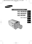
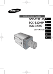
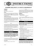
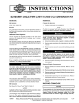
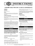
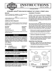
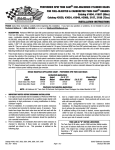
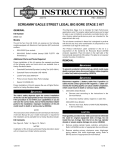
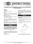
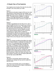
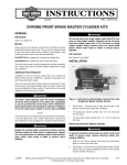
-J04198
REV. 2007-05-25
TWIN CAM CRANKCASE BORING TOOL
NOTE
When reassembling the engine, Harley-Davidson recommends
replacing the Original Equipment cylinder studs with Screamin'
Eagle High Tensile Studs (16505-01).
GENERAL
Kit Number
94419-06
Models
is03456
This tool can be used to modify 1999 and later Twin Cam
engines.
Additional Tools and Materials Required
•
Hex wrenches: 1/8 in., 3/16 in., 1/4 in. and 5/16 in.
•
7/16 in. wrench
•
Torque wrench
•
1/2 in. socket
•
Calipers
•
Heavy-duty, 15 inch drill press or milling machine
•
Cutting fluid
•
Harley-Davidson® SAE 20w50 motorcycle oil
The procedures in this instruction sheet should be performed by one experienced in precision measuring techniques. Failure to meet tolerances called for in this
instruction sheet can result in engine damage. (00511b)
The rider's safety depends upon the correct installation
of this kit. Use the appropriate service manual procedures.
If the procedure is not within your capabilities or you do
not have the correct tools, have a Harley-Davidson dealer
perform the installation. Improper installation of this kit
could result in death or serious injury. (00333a)
Figure 1. Cylinder Wall
2.
Remove cylinder studs from the engine crankcase.
3.
Mask off all bearings and oil holes to prevent debris and
contaminants from entering those areas.
4.
Inspect and clean engine case mating surfaces.
5.
Bolt engine case together with the stock hardware, except
the top center screw between the cylinders (Figure 2), and
tighten to the specifications listed in the Service Manual.
NOTE
To prevent damage to tool, it is important to replace the stock
top center screw with the top center screw included in this kit
(Part Number 1093).
6.
NOTE
See Figure 10. Install the top center screw (25) included
with this kit between the cylinders and tighten to 50-90 inlbs (5.6-10.2 Nm).
This instruction sheet references Service Manual information.
A Service Manual for your model motorcycle is required for
this installation and is available from a Harley-Davidson Dealer.
NOTE
When assembling the engine cradle, lubricate all of the hardware with clean SAE 20w50 Harley-Davidson® motorcycle oil.
Kit Contents
7.
See Figure 10 and Table 1.
ENGINE AND TOOL PREPARATION
1.
Refer to the appropriate Service Manual and remove and
disassemble the engine.
-J04198
See Figure 10. Assemble the engine cradle as follows:
a.
Ensure all mating surfaces are clean.
b.
Determine which left support plate to use for in the
engine cradle assembly.
For early model engines (1999-2005 Dyna models;
1999-2006 Touring models and 2000-2006 Softail):
Use left side support plate (1).
Many Harley-Davidson® Parts & Accessories are made of plastics and metals which can be recycled.
Please dispose of materials responsibly.
1 of 9
For later model engines (2006 and later Dyna
models; 2007 and later Softail and Touring
models): Use left support plate (7).
8.
9.
c.
Install left support plate (1 or 7) to base plate (2) with
four screws (10) for early models or three screws for
later models. Tighten screws to 120 in-lbs (13 Nm).
d.
Determine which side of the right support plate should
face the engine cradle assembly. If boring an unbalanced (Alpha) engine or a 2007 or later Softail engine,
ensure side "A" faces outward, away from the engine
cradle. If boring a balanced (Beta) engine except a
2007 or later Softail engine, ensure side "B" faces
outward, away from the engine cradle.
e.
Install right support plate (3), with the appropriate side
facing the engine cradle assembly, to the base plate
(2) with three screws (10) and washers (23). Tighten
screws to 120 in-lbs (13 Nm).
Install the engine case into the engine cradle. Rotate the
engine case so that either the front or rear cylinder deck
is facing up and horizontal.
Lubricate two 1/4 inch screws (11) with SAE 20w50 HarleyDavidson motorcycle oil. If the front cylinder is being bored,
install the screws in the right support plate holes marked
"F". If the rear cylinder is being bored, install the screws
in the alignment plate holes marked "R". This will align the
cylinder spigot bore perpendicular to the base. Do not
tighten at this time.
is03462
Figure 2. Engine Crankcase in Engine Cradle
is03463
10. Lubricate two 1/4 inch screws (11) and one 5/16 inch
screw (14) with SAE 20w50 Harley-Davidson motorcycle
oil. If the front cylinder is being bored, install the screws
in the left mounting plate holes marked "F". If the rear
cylinder is being bored, install the screws in the mounting
plate holes marked "R". This will align the cylinder spigot
bore perpendicular to the base. Do not tighten at this time.
11. See Figure 2. Install T-pin (Figure 10, Item 15) into the
alignment plate in the hole locations shown. If the front
cylinder is being bored, install the T-pin in the alignment
plate hole marked "F". If the rear cylinder is being bored,
install the T-pin in the alignment plate hole marked "R". It
may be necessary to rotate the engine case slightly in
order to install the T-pin.
12. Tighten screws (11) to 90-120 in-lbs (10-13 Nm).
13. Tighten screws (14) to 156-180 in-lbs (18-20 Nm).
Figure 3. Install T-pin into Engine Crankcase and Engine
Cradle
NOTE
Failure to check the cylinder dowel clearance may result in the
final spigot bore being out of center.
14. See Figure 10. Cylinder dowel height may vary, verify that
there is sufficient clearance between the machined reliefs
-J04198
2 of 9
of the boring head assembly locating plate (5) and the
cylinder dowels of the neighboring cylinder as follows:
a.
Place the boring head assembly on the engine
crankcase with a 1-1/2 - 2 in. (38 - 50 mm) wood block
between boring head assembly plates to prevent the
boring head from contacting the engine crankcase
(see Figure 7).
b.
Lubricate two screws (10) with SAE 20w50 HarleyDavidson motorcycle oil. Install but do not tighten the
two screws, then place a piece of paper between the
neighboring crankcase cylinder dowel and the locating
plate.
c.
Tighten the screws to 18-20 ft-lbs (25-27 Nm), then
ensure the paper moves freely between the cylinder
dowel and the support plate.
is03455
1
If the paper does not move freely, the cylinder dowel
is too high, and the dowel must be installed deeper
or removed.
If the cylinder dowel is damaged during removal it will
need to be replaced.
d.
Repeat Step 14 for opposite cylinder.
15. See the appropriate Boring Head Setup section below and
setup the boring head for your application.
is03459
7
1
9
11
3
Boring Head Setup - Spigot Bore
4
2
1
6
8
10
Set screw, outward locking
Set screw, inward locking
Set screw, depth
Rough cut tool bit
Finish cut tool bit
Boring diameter
Finish cut and boring head width
Rough cut and boring head width
Rough cut
Finish cut
Boring head diameter
Figure 4. Boring Head - View of Bottom Side
-J04198
NOTES
It is recommended that no more than 0.125 in. (3.175 mm) of
the diameter be removed in one pass. The engine crankcase
machining may require more than one pass and more than
one boring head set-up to obtain the final bore. Attempting to
remove more than the recommended amount of material in
one pass may result in a rough finish and/or damage to the
bore and tool bits.
1.
3
1.
2.
3.
4.
5.
6.
7.
8.
9.
10.
11.
Figure 5. Boring Head Assembly
If the tool bits are set for a bore larger than 4.45 in. (113.03
mm), the tool bits will contact and cause damage to the inner
diameter of the locating plate (Figure 10, Item 5) and/or tool
bits (Figure 10, Item 16).
2
5
2
1. Depth adjustment screw
2. Cylinder dowel reliefs
Remove two screws (10) and the boring head
assembly.
e.
2
See Figure 4. Install the cutting bits into the bore head
and set boring diameter as follows:
a.
Using a 1/8 inch hex key wrench, thread six set
screws into the cutting head. Do not thread them into
the holes far enough to prevent the cutting bits from
being inserted into the bore head.
b.
Install the tool bits into the bore head oriented as
shown.
c.
See Figure 6. See the Instruction Sheet for the cylinder kit being installed to determine final spigot bore
diameter. Subtract the stock spigot bore diameter (5)
from the final spigot bore diameter (4) to determine
the diameter difference. Divide by two to determine
radius difference (3).
If the radius difference is 0.0625 in. (1.5875 mm)
or less, divide it by 2, this is the setback of the rough
cut tool bit from the finish cut tool bit.
The finish tool bit protrusion is the finish spigot bore
radius less the boring head radius. The rough tool bit
protrusion is the finish spigot bore radius less 1/2 the
radius difference (3) less the boring head radius.
If the radius difference is 0.0625 in. (1.5875 mm)
or more, the bore cut will require two passes. The
first pass should be 1/2 of the total cut.
3 of 9
The finish tool bit protrusion for the first pass is the
finish spigot bore radius less 1/2 the radius difference
less the boring head radius. The rough tool bit protrusion for the first pass is the finish spigot bore radius
less 1/2 the radius difference less 1/4 the radius difference less the boring head radius.
Boring Head Setup - O-Ring Counterbore (Where
Applicable)
NOTES
The finish tool bit protrusion for the second pass is
the finish spigot bore radius less the boring head
radius. The rough tool bit protrusion for the second
pass is the finish spigot bore radius less 1/4 the radius
difference less the boring head radius.
It is recommended that no more than 0.125 in. (3.175 mm) of
the diameter be removed in one pass. The engine crankcase
machining may require more than one pass and more than
one boring head set-up to obtain the final bore. Attempting to
remove more than the recommended amount of material in
one pass may result in a rough finish and/or damage to the
bore and tool bit.
d.
See Figure 4. Set the rough cut (4) and finish cut (5)
tool bit depths using the set screws (3). Use an
appropriate measuring tool to ensure accurate
measurements.
If the tool bit is set for a bore larger than 4.45 in. (113.03 mm),
the tool bit will contact and cause damage to the inner diameter
of the locating plate (Item 5, Figure 10) and/or tool bit (Item
16, Figure 10).
e.
While ensuring that the tool bits are pressed tight to
the depth set screws (3), tighten the locking set
screws (1), then locking set screws (2). Tighten
locking set screws to 90 in-lbs (10 Nm).
Due to the shallow depth of the O-ring counterbore cut,
only the finish cut tool bit will be installed. Two passes
will be necessary to achieve the final cut dimension.
is03606
3
1.
See Figure 4. Install the finish cut tool bit into the bore
head and set boring diameter as follows (Do NOT install
the rough cut tool bit when cutting the O-ring counterbore.):
a.
2
The finish tool bit protrusion for the first pass is the
finish O-ring counterbore radius less 1/2 the radius
difference less the boring head radius.
The finish tool bit protrusion for the second pass is
the finish O-ring counterbore radius less the boring
head radius.
1
b.
Set the finish cut (5) tool bit depth using the set screw
(3). Use an appropriate measuring tool to ensure
accurate measurements.
c.
While ensuring that the tool bit is pressed tight to the
depth set screw (3), tighten the locking set screw (1),
then locking set screw (2). Tighten locking set screws
to 90 in-lbs (10 Nm).
5
4
1.
2.
3.
4.
5.
See the Instruction Sheet for the cylinder kit being
installed to determine final O-ring counterbore diameter. Subtract the stock O-ring counterbore diameter
from the final O-ring counterbore diameter to
determine the diameter difference. Divide by two to
determine radius difference.
Finish cut radius
Stock bore radius
Depth of finish cut (radius difference)
Finish cut diameter
Stock bore diameter
Figure 6. Calculate Tool Bit Settings
2.
Set the bore depth as follows:
a.
See the Instruction Sheet for the cylinder kit being
installed to determine final spigot bore depth.
b.
Using a 1/8 inch hex key wrench and a 7/16 inch
wrench, adjust the stop depth adjustment screw (19)
on the boring assembly.
c.
Measuring from the finish cut tool bit to the bottom of
the locating plate as shown in Figure 5, adjust the
stop depth adjustment screw so that the finish tool bit
will cut to the desired depth.
d.
Secure stop depth adjustment screw (19) with nut
(20).
-J04198
4 of 9
2.
Set the boring head O-ring counterbore depth as follows:
BORING PROCEDURE
a.
See the Instruction Sheet for the cylinder kit being
installed to determine final O-ring counterbore depth.
NOTES
b.
See Figure 10. Remove the stop depth adjustment
screw (19), nut (20) and washer (26).
For best boring results, use a well maintained and dependable
drill press or milling machine. If you use equipment of poor
quality or condition, inaccurate boring may result.
c.
Install washer (26) and nut (20) onto the alternate
stop depth adjustment screw (24), then install the
screw so the head of the screw is between the plates
of the boring head assembly.
d.
Using a 1/8 inch hex key wrench and a 7/16 inch
wrench, adjust the stop depth adjustment screw (24)
on the boring assembly top plate down to the locating
plate.
e.
Measuring from the finish cut tool bit to the bottom of
the locating plate as shown in Figure 5, adjust the
stop depth adjustment screw so that the finish tool bit
will cut to the desired depth.
f.
For applications requiring an O-ring counterbore, cut the spigot
bore before cutting the O-ring counterbore.
All boring operations have some degree of dimensional runout.
This runout should be assessed and adjusted for by performing
a test cut or after a first pass.
Determine dimensional runout as follows:
•
After the first pass or test cut, measure the bore actual cut
diameter, then subtract the actual cut diameter from the
intended diameter and divide by 2.
•
Example: If the actual cut diameter measures 4.362 in.
and the intended diameter was 4.358 in. then the bore is
0.004 in. over-size (4.362 in. - 4.358 in. = 0.004 in.). Divide
by 2 to determine dimensional runout adjustment (0.004
in. / 2 = 0.002 in.). In this example, when setting the bore
head for the second pass, the finish tool bit setting would
be reduced by 0.002 in.; e.g., if the final bore diameter is
intended to be 4.415 in., then adjust finish tool bit protrusion (0.482 in.) for dimensional runout (0.002 in. over-size)
by subtracting 0.002 in. from the second pass finish tool
bit protrusion (0.482 in. - 0.002 in. = 0.480 in.).
1.
Place the engine crankcase/cradle without the boring head
assembly installed onto a drill press or milling machine
table.
Secure stop depth adjustment screw (24) with nut
(20).
is03457
Figure 7. Insert 1-1/2 in. - 2 in. Block of Wood
is03517
1
NOTE
Assemble a dial indicator into the drill press chuck or milling
machine collet and "sweep" the cutting surface of the engine
crankcase to ensure that the cutting surface is perpendicular
to the spindle of the drill press or milling machine. If it is not,
shim between the crankcase/cradle assembly and the drill
press or milling machine table. Adjust as necessary until the
cutting surface is perpendicular to the spindle.
2.
Check and ensure cutting surface is perpendicular to
spindle of drill press or milling machine.
3.
See Figure 7. Place a block of wood between boring head
assembly plates to prevent the boring head from contacting
the engine crankcase.
4.
See Figure 10. Lubricate two screws (10) with SAE 20w50
Harley-Davidson motorcycle oil. Install the boring head
assembly onto the engine crankcase with two lubricated
socket head cap screws.
2
Ensure that the boring head assembly locates properly on
the cylinder dowels and sits flush on the engine crankcase.
Tighten the cap screws to 18-20 ft-lbs (25-27 Nm).
NOTE
If using a chuck, be sure the chuck jaws locate on the flats on
the boring head shaft.
5.
Center the shaft of the boring head into the chuck or collet
of the drill press or milling machine. Tighten the chuck or
collet and remove the wood block from the boring head
assembly.
6.
Clamp the assembly to the drill press or machining table.
Use the holes in the engine cradle base plate for clamping,
1. O-ring bore
2. Spigot bore
Figure 8. Cylinder Spigot and O-Ring Counterbore
Dimensions
-J04198
5 of 9
if possible. If it is not possible, use C-clamps or similar
clamps to secure the assembly.
NOTE
When raising and lowering the boring head to check for binding,
ensure that the boring head and tool bits do not strike the
engine crankcase. Damage to the tool or crankcase may result.
7.
Lubricate the two guide dowels of the boring head
assembly with light oil. Raise and lower the boring head
to ensure that there is no binding in the motion.
8.
Set the drill's or machine's speed to approximately 600800 RPMs. Ensure the boring head is fully raised, then
start the drill or machine. Check the boring head and the
table for vibration. If there are no vibrations, the drill speed
can be increased. If there are vibrations, reduce the drill
speed. 600-800 RPMs is the recommended drill speed.
NOTE
Boring with a slow and steady feed rate will provide cleaner
finish.
9.
NOTES
When boring the O-ring counterbore, move the boring head
down very slowly.
When the stop bottoms out, STOP! Do not apply pressure to
the cutting head after the stop bottoms out.
16. For O-ring counterbore (where applicable):
a.
See the Boring Head Setup - O-Ring Counterbore
section of this Instruction Sheet and setup boring head
assembly for O-ring counterbore (first pass). Note:
only the finish cut tool bit will be used for this bore.
b.
See Step 5 of this section and assemble the boring
head assembly onto the engine crankcase.
c.
Repeat the Boring Procedure above and bore the Oring counterbore. Note that a minimum of two passes
will be required for each cylinder.
d.
Repeat Steps 16a-16c with boring head assembly
setup for second pass bore cut, adjusted for
dimensional runout (see note at beginning of section).
Bore the engine crankcase as follows:
a.
b.
c.
While applying cutting fluid as necessary, begin boring
with a slow, even pressure until the boring assembly
stop bottoms out.
Shut down the drill or milling machine and wait until
the boring head comes to a complete stop.
Slowly and carefully retract the boring head from the
engine crankcase.
10. See Figure 7. Replace the block of wood between boring
head assembly plates to prevent the boring head from
contacting the engine crankcase.
11. Remove two socket head cap screws and the boring head
assembly from the engine crankcase.
NOTE
If the application requires that the final bore cut be taken in two
passes, repeat Steps 7 - 11 with the boring head assembly
setup for the second pass bore cut, adjusted for dimensional
runout (see note at the beginning of this section).
12. See Figure 10. Remove two 1/4-20 inch socket head cap
screws (11), T-pin (15) and three 5/16-18 inch socket head
cap screws (14) (or two 1/4-20 inch screws (11) and one
5/16 inch screw (14) depending on application), then rotate
the engine crankcase so that the opposite engine crankcase spigot bore is straight up.
13. Reinstall the hardware removed in the previous step
according to the instructions given in the Steps 9 - 13 of
the ENGINE AND TOOL PREPARATION section of this
Instruction Sheet.
14. See Step 5 in this section and reinstall the boring head
assembly to the engine crankcase.
15. Repeat Steps 7 - 11 of this section for the opposite cylinder.
-J04198
17. Remove engine crankcase/tool assembly from the drill
press or milling machine. Remove engine crankcase from
tool.
NOTE
To prevent severe engine damage, thoroughly clean and
remove all chips and debris from the engine crankcase after
boring.
18. Disassemble crankcase and wash (or clean) chips and
debris from engine crankcase halves necessary.
19. See Figure 9. Using a 11/32 inch drill bit, drill out the
existing threads of the top center screw hole. Drill to a
depth of 0.79 inches from the gasket surface.
20. Using a size "F" in. drill bit, extend the top center screw
hole 1.00 in. (25.4 mm) (maximum) to a depth of 1.79 in.
(45.46 mm) from the gasket surface.
21. Using a 5/16-18 inch bottoming tap, tap the screw hole to
a minimum depth of 1.59 in. (40.39 mm) from the gasket
surface.
22. See Figure 1 and Figure 9. Remove the thin material
between the cylinders next to the top center screw as
shown, by using a 5/8 inch ball end mill and milling a 5/16
in. radius at the two points shown.
23. Refer to the appropriate Service Manual and assemble
the engine with the following changes:
a.
Tighten all of the engine crankcase screws to the
specified torque, except the top center engine
crankcase screw.
b.
After the cylinders and heads have been installed and
the hardware tightened to specification, install the top
center engine crankcase screw provided in the HarleyDavidson 110 Inch kit or Screamin' Eagle Pro BiggerBore Cylinder kit (Part Number 1090). Tighten the
screw to 50-90 in-lbs (5.6-10.2 Nm).
6 of 9
is03502
2
3
4
10
1
5
6
1.
2.
3.
4.
5.
10
Tap hole with a 5/16-18 UNC-2B bottoming tap
Extended full thread depth - 0.80 in. (20.32 mm)
Distance - 0.48 in. (12.19 mm)
Distance - 0.48 in. (12.19 mm)
Drilled hole diameter - 0.34 in. (8.64 mm)
7
8
6.
7.
8.
9.
10.
9
Extend hole depth - 1.00 in. (25.4 mm) (maximum)
Unthreaded hole depth - 0.79 in. (20.07 mm)
Distance to center of crank - 5.90 in. (149.86 mm)
Distance to center of crank - 6.00 in. (152.40 mm)
Radius - 0.31 in. (7.87 mm) (Use 5/8 in. ball end
mill)
Figure 9. Top Center Engine Crankcase Bolt Hole Modification
-J04198
7 of 9
SERVICE PARTS
21
is03452
19
18
20
13
13
26
6
24
8
4
16
16
17
22
9
10
10
7
5
3
11
25
11
14
11
1
2
11
15
12
23
10
12
11
14
12
12
10
Figure 10. Service Parts for Twin Cam Crankcase Boring Tool
-J04198
8 of 9
Table 1. Service Parts Table
Item
Description (Quantity)
Part Number
1
Support plate, left, early
94428-06
2
Base plate
94433-06
3
Support plate, right
94440-06
4
Boring head
94460-06
5
Locating plate
94469-06
6
Support plate, boring assembly
94470-06
7
Support plate, left, late
94515-06
8
Shielded bearing, 7/8 X 2 X 9/16 in.
94547-06
9
Dowel, pull out, 1/2 X 3-1/2 in.
94516-06
10 Socket head cap screw, 3/8-16 X 1 in. (9)
4659
11 Socket head cap screw, 1/4-20 X 1 in. (4)
4661
12 Dowel pin, 1/4 X 3/4 in. (4)
94526-06
13 Bushing, 0.502 in. I.D. X 0.75 O.D. X 0.75 Long (2)
94541-06
14 Socket head cap screw, 5/16-18 X 1 in. (3)
4662
15 T-pin, 3/8 in shaft
94551-06
16 Tool bit, carbide, 3/8 in. (2)
94552-06
17 Set screw, 1/4-28 X 1/2 in. (6)
4663
18 Washer, 1/4 in.
6927
19 Set screw, 5/16-18 X 1-3/4 in.
4664
20 Nut, 5/16-18
8086
21 Button head cap screw, 1/4-20 X 1/2 in.
4665
22 Dowel pin, 1/2 X 3-1/2 in.
94559-06
23 Washer, 3/8 in. (3)
6920
24 Socket head cap screw, 5/16-18 X 2-1/4 in.
4672
25 Flange screw
1093
26 Washer, 5/16 in.
6933
-J04198
9 of 9