1
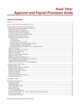
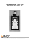
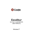
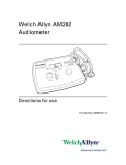
User’s Manual
Firmware v. 1.0 April 2010
SMART TONE User’s Manual
Table Of Contents
Installation
1
Welcome .................................................................................... 1
Audiometer Installation ............................................................... 1
Key to Numbers in Diagram ....................................................... 2
Connecting the Printer to the Audiometer.................................. 3
Printer Setup ............................................................................... 3
Data Transfer .............................................................................. 5
Installing the Windows Driver for Data Transfer ......................... 5
Changing the Audiometer’s COM Port on the Computer ........ 12
Audiometer Controls
13
Main Screen .............................................................................. 13
Test Display .............................................................................. 13
Audiogram Graph ..................................................................... 15
Toolbar Buttons ........................................................................ 15
Menu Toolbar Button............................................................... 16
Microphone .............................................................................. 16
Save/Print Toolbar Button ....................................................... 17
Test Toolbar Button ................................................................. 18
Audiometer Control Functions ................................................. 19
Instructions for Common Audiometer Tasks ............................. 21
Keypad ..................................................................................... 21
Utilities ..................................................................................... 22
Examiner ID ............................................................................. 23
Subject ID ................................................................................ 24
Audiometer Setup
25
Audiometer Setup ..................................................................... 25
Setting the Date and Time ........................................................ 25
Alarm Mode ............................................................................. 26
Automatic Testing
27
Test Configuration .................................................................... 27
Errors ........................................................................................ 27
Test Sequence ........................................................................... 28
Automatic Retests ..................................................................... 30
Threshold Determination .......................................................... 30
Manual Testing
31
Printout
33
Typical Procedure of Operation
35
Verifying Correct Audiometer Setup ........................................ 35
© 2010 SMART DIAGNOSTIC DEVICES
i
SMART TONE User’s Manual
Verifying Correct Audiometer Operation ................................. 35
Performing an Audiogram ......................................................... 35
Beginning Automatic Testing ................................................... 36
Saving an Audiogram ................................................................ 36
Printing the Current Audiogram ............................................... 37
Procedures for Data Transfer ..................................................... 38
Real-Time Transfer .................................................................. 38
Batch Transfer........................................................................... 38
Storage
39
Audiograms ............................................................................... 40
Viewing a Stored Audiogram .................................................... 40
Storage Menu ........................................................................... 40
Tagging Audiograms ................................................................. 41
Clearing Audiogram Tags ......................................................... 42
Deleting an Audiogram ............................................................. 42
Printing a Stored Audiogram ..................................................... 43
Filtering Audiograms by Subject ID .......................................... 43
Data Validation ......................................................................... 44
Memory Usage ......................................................................... 44
Touchscreen Care and Calibration
45
Touchscreen Use and Care ....................................................... 45
Setting the Display Brightness ................................................... 45
Touchscreen Calibration ........................................................... 45
Safety and Audiometer Care
46
Power Supply Safety ................................................................. 46
Audiometer Care ...................................................................... 46
Daily Calibration Check
48
Daily Calibration Check Using the Bio-Acoustic Simulator ...... 48
Installing the Bio-Acoustic Simulator ........................................ 48
Key to Numbers in Diagram ..................................................... 49
Annual Calibration Mode
50
Postponing the Annual Calibration Warning ............................. 50
Trademarks
51
Warranty
51
Abbreviations
52
Audiometer Specifications
53
© 2010 SMART DIAGNOSTIC DEVICES
ii
SMART TONE User’s Manual
Installation
Welcome
Congratulations on your purchase of the SMART TONE automatic
audiometer, an advanced, easy-to-use pure-tone threshold audiometer. The
intelligent features and user-friendly controls of the SMART TONE
streamline the testing process to efficiently collect hearing thresholds at seven
frequencies. The SMART TONE stores audiograms, and can print results to
an optional external printer or transfer them to third-party software.
Audiometer Installation
To install the audiometer:
Refer to the figure below.
1. Insert the blue headset connector into the blue LEFT jack, and the red
headset connector into the red RIGHT jack on the back panel.
2. Insert the connector for the response switch into the RESPONSE jack
on the back panel.
If you are using an audiometric test booth, use patch cords to make
connections through the booth patch panel.
3. Connect the cord of the power supply to the POWER jack on the back
panel of the audiometer.
4. Plug the power supply into a wall outlet.
5. Turn on the power switch on the back panel of the instrument.
The LCD display on the instrument’s top panel will illuminate,
indicating that the audiometer is on.
© 2010 SMART DIAGNOSTIC DEVICES
1
SMART TONE User’s Manual
Audiometer with optional printer
Key to Numbers in Diagram
1.
2.
3.
4.
5.
6.
7.
Power supply (audiometer)
Response switch
Audiometer
Serial cable
Headset
Thermal printer
Power supply (printer)
© 2010 SMART DIAGNOSTIC DEVICES
2
SMART TONE User’s Manual
Connecting the Printer to the
Audiometer
The supported external printer for the audiometer is a Seiko DPU-414 using
4-inch thermal paper.
For information on purchasing this printer, contact your Smart Diagnostic
Devices distributor. To find the distributor nearest you, contact Smart
Diagnostic Devices at (612) 548-5556.
To connect the printer to the audiometer:
Ø Using a cable, connect the printer to the port on the audiometer back
panel labeled "PRINTER".
Printer Setup
If the printer has been purchased from Smart Diagnostic Devices or a Smart
Diagnostic Devices distributor, it has already been configured according to the
following procedure.
Otherwise, follow the procedure below to set up the printer. The printer must
be properly configured before it can operate with the audiometer.
When completed, the configuration is stored within the printer and will not
be lost if power is removed from the printer.
If any mistakes are made while executing the procedure below, simply switch
the power to the printer OFF, then restart the procedure. Further information
can be found in the "DPU-414 Operation Manual."
To configure the printer:
1. Switch off the printer.
2. Press and hold the ONLINE button while switching the printer back on.
Release only after a list of current settings starts to print out.
Beyond the following step, configuration settings must be entered sequentially.
It is not possible to undo the settings without restarting the procedure. If a
mistake is made, start the procedure beginning with step 1.
3. Press the ONLINE button once to begin entering settings for DIP SW1.
4. Press the buttons EXACTLY according to the following sequence and
check that the resulting message is correct:
Press button:
Verify message:
FEED
1 (OFF) : Input = Serial
© 2010 SMART DIAGNOSTIC DEVICES
3
SMART TONE User’s Manual
ONLINE
2 (ON ) : Printing Speed = High
ONLINE
3 (ON ) : Auto Loading = ON
ONLINE
4 (ON ) : Auto LF = ON
ONLINE
5 (ON ) : Setting Command = Enable
FEED
6 (OFF) : Printing
ONLINE
7 (ON ) : Density
ONLINE
8 (ON ) : = 100%
5. Next, press ONLINE again to begin entering settings for DIP SW2.
6. Press the buttons, similar to step 4, and verify the message:
Press button:
Verify message:
ONLINE
1 (ON ) : Printing Columns = 40
FEED
2 (OFF) : User Font Back-up = OFF
ONLINE
3 (ON ) : Character Select = Normal
FEED
4 (OFF) : Zero = Slash
ONLINE
5 (ON ) : International
ONLINE
6 (ON ) : Character
ONLINE
7 (ON ) : Set
FEED
8 (OFF) : = U.S.A
7. Press ONLINE once more to enter the settings for DIP SW3.
8. Press the buttons and verify the message:
Press button:
Verify message:
ONLINE
1 (ON ) : Data Length = 8 bits
FEED
2 (OFF) : Parity Setting = Yes
FEED
3 (OFF) : Parity Condition = Even
ONLINE
4 (ON ) : Busy Control = H/W Busy
FEED
5 (OFF) : Baud
ONLINE
6 (ON ) : Rate
ONLINE
7 (ON ) : Select
FEED
8 (OFF) : = 19200 bps
9. Press ONLINE one more time to finish. Settings are saved to memory and
the entire list of current settings will print out. Double-check the re-printed
© 2010 SMART DIAGNOSTIC DEVICES
4
SMART TONE User’s Manual
settings against the above steps. If the settings do not match, perform the
procedure again beginning with step 1.
Data Transfer
Data transfer of one or more audiograms sends a copy of the audiogram(s) to
the database management system that you are using on the computer. The
database management system that you are using must support the RA500
communication protocol, which is the communication protocol used by the
SMART TONE audiometer for data transfer. Transfer is initiated using the
database.
For transfer, the audiometer must be connected to the computer with a cable.
In addition, the data transfer software on the included CD must be installed on
the computer. See the next sections.
In your database management system, select the RA500 as the audiometer
with which the computer will communicate.
The audiometer is already set up for data transfer. No adjustments are
necessary. Data transfer is initiated from the third-party software. Set the
communication parameters in the third-party software to 9600 baud, 8 data
bits, no stop bits, no parity.
In some database management systems, the COM port assigned to the
audiometer must be between COM1 and COM4. A procedure for changing
the COM port is supplied in the section called Changing the Audiometer’s
COM Port on the Computer on page 12.
Installing the Windows Driver for Data
Transfer
To connect the audiometer to third-party software on the computer, you will
need to install the driver on the included CD onto the computer, which
makes the audiometer appear as a COM port on the computer. Windows XP,
Vista (32-bit or 64-bit) and Windows 7 (32-bit or 64 bit) operating systems
are supported. The connection uses one USB port.
Refer to the procedures below. The instructions differ depending on which
Windows operating system your PC is running.
© 2010 SMART DIAGNOSTIC DEVICES
5
SMART TONE User’s Manual
To install the driver on a computer using Windows 7:
1. With the computer running, connect the audiometer to the computer
using a cable, and turn on the audiometer power switch.
The following dialog box appears.
2. In order to install the driver, open the Device Manager as shown below
and double-click on “SmartTone Virtual Communications Port”. The
“Properties” dialog box appears:
© 2010 SMART DIAGNOSTIC DEVICES
6
SMART TONE User’s Manual
3. Click the Update Driver button.
A dialog box appears, asking you the location of the driver software.
Choose “Browse my computer for driver software.”
4. The drive location of the CD must be selected manually. Insert the CD
that came with the audiometer. Enter the drive letter, or browse to the
CD drive using the Browse button.
© 2010 SMART DIAGNOSTIC DEVICES
7
SMART TONE User’s Manual
5. Click Next, then Close on the final dialog box.
© 2010 SMART DIAGNOSTIC DEVICES
8
SMART TONE User’s Manual
To install the driver on a computer using Windows Vista:
1. With the computer running, connect the audiometer to the computer
using a cable, and turn on the audiometer power switch.
The “Found New Hardware” dialog box appears.
© 2010 SMART DIAGNOSTIC DEVICES
9
SMART TONE User’s Manual
2. Choose the option called “Locate and install driver software.”
A dialog box appears, asking you to insert the disc that came with the
audiometer.
3. Insert the CD in the drive, and clock Next.
4. When the installation is complete, click Close.
© 2010 SMART DIAGNOSTIC DEVICES
10
SMART TONE User’s Manual
To install the driver on a computer using Windows XP:
1. With the computer running, connect the audiometer to the computer
using a cable, and turn on the audiometer power switch.
The Hardware Update Wizard appears, asking you to insert a disk.
2. Insert the CD that came with the audiometer into the computer’s CD
drive, and click Next.
The software will be automatically installed.
A dialog box appears, informing you that the installation was successful.
3. Click Finish.
© 2010 SMART DIAGNOSTIC DEVICES
11
SMART TONE User’s Manual
Changing the Audiometer’s COM Port
on the Computer
In some database management systems, the COM port assigned to the
audiometer must be between COM1 and COM4. This section explains how
to change the COM port on a Windows PC.
To change the audiometer’s COM port on the computer:
1. Open the Device Manager.
2. Under Ports, right-click on the audiometer’s COM port and choose
Properties from the menu.
The Properties dialog box appears.
3. Choose the Port Settings tab.
4. Choose the Advanced button.
The Advanced Settings dialog box appears.
5. In the COM Port Number combo box, choose the desired COM port.
6. Choose OK.
© 2010 SMART DIAGNOSTIC DEVICES
12
SMART TONE User’s Manual
Audiometer Controls
Main Screen
The main screen of the audiometer is pictured below. The audiogram
information fields are at the top with the test display underneath, and the
toolbar is to the right. The audiogram graph is at the bottom.
Main Screen of the Audiometer, shown in Idle status
Test Display
The on-screen display gives information on the stimulus presented, subject
response, test status and progress, Subject ID, and Examiner ID.
Hearing threshold levels determined manually will be updated in the Hearing
Thresholds table and the graph on the main screen, provided that the “OK”
button (not “Cancel”) is chosen in the Manual dialog box.
© 2010 SMART DIAGNOSTIC DEVICES
13
SMART TONE User’s Manual
The sections displayed are described below.
Section
Description
Subject ID
Displays Subject ID if one has been entered.
Examiner ID
Displays Examiner ID if one has been entered.
Left
Displays test data or progress by frequency for the left ear.
Number
Threshold in dB HL
(blue)
Number
current stimulus in dB HL being presented.
(white on blue
background)
NT
Not tested. Indicates that a frequency has not
been tested, or was not selected for test.
NR
No response. The subject did not respond to two
stimulus presentations at the maximum intensity.
MR
Multiple response. The subject responded twice
or more to a single stimulus presentation.
SE
Subject error. A threshold was not determined in
20 stimulus presentations.
CR
Continuous response. The hand switch was not
released since the start of the previous stimulus
presentation.
RN
Retest not valid. The threshold of the 1kHz
programmed retest varied by more than 5 dB.
PT
Presentation time-out. More than sixty seconds
have elapsed from the start of a threshold
determination without a threshold being
established.
Right
Displays test data or progress by frequency for the right ear, with red
used instead of blue. See above for explanation of contents.
Status
Displays current audiometer status. One of five messages is displayed:
Idle
not testing
Testing
automatic test in progress
Finished
automatic test is complete
Error
the test has stopped because of an error that occurred
during automatic testing
Mic On
talk-over microphone is enabled
© 2010 SMART DIAGNOSTIC DEVICES
14
SMART TONE User’s Manual
Audiogram Graph
A graph displaying the audiogram thresholds for the left and right ears appears
on the main screen. Left ear hearing levels are marked with an "X" and plotted
in blue. Right ear hearing levels are marked with an "O" and plotted in red.
Main Screen with Audiogram Graph
showing Left Ear and Right Ear plotted
Toolbar Buttons
The toolbar buttons on the main screen are listed below, together with an
explanation of their function and a section reference.
Button Name
Menu
Mic
Function
Section
Enter Examiner ID;
access to Storage,
audiometer setup, and
Utilities.
Menu Toolbar Button, page 16
Turns on the
microphone.
Microphone, page 16
Turns off the alarm.
Microphone, page 16
Save or print an
audiogram.
Saving an Audiogram, page 36
Testing controls.
Test Toolbar Button, page 18
Alarm Off
Save/Print
Printing the Current Audiogram, page 37
Test
© 2010 SMART DIAGNOSTIC DEVICES
15
SMART TONE User’s Manual
Menu Toolbar Button
The Menu toolbar button on the main screen, when pressed, displays the
following menu items, which are listed with their function and a section
reference in the table below.
Menu Toolbar Button with menu items
Menu Item
Function
Section reference
Enter Examiner ID
Enter Examiner ID.
Examiner ID, page 19
Storage
Access to stored
audiograms.
Storage, page 39
Setup
Access to test
configuration and
error alarm settings.
Audiometer Setup, page 25
Utilities
Annual calibration,
set date and time,
touchscreen
calibration, and
adjust display
settings.
Annual Calibration, page 53
Setting the Date and Time, page
25
Touchscreen Calibration, page 45
Setting the Display Brightness, page
45
Microphone
The talk-over microphone enables you to speak to the subject in a test booth
through the headset. For automatic audiograms, the microphone is enabled by
the Mic toolbar button on the audiometer's main screen. For manual
audiograms, the microphone is enabled by the Mic button in the lower left
© 2010 SMART DIAGNOSTIC DEVICES
16
SMART TONE User’s Manual
corner of the Manual dialog box. In both cases, the Microphone On dialog
box appears. This dialog box will remain on the screen until the microphone
is disabled.
When the microphone is enabled, an automatic test is stopped, and the Status
box in the Test Display shows “Mic On”. The threshold that was currently
being determined is reset in the Test Display to the previous threshold
determined or “NT.”
When the microphone is disabled, the automatic test remains stopped, and the
word “Idle” appears in the Status box. In order to continue testing after using
the microphone, choose Start Audiogram from the Test toolbar button menu.
The Microphone On dialog box contains a slide volume control: adjust this
control either by touching the desired setting, or by pressing the arrow keys.
The Volume box shows the current level.
The dialog box also contains a Mic Off button, which will turn off the
microphone when it is pressed.
Refer to the procedures below for microphone controls.
To enable the microphone during an automatic audiogram:
Ø On the main screen, press the Mic toolbar button. This action also stops
the test.
To enable the microphone during a manual audiogram:
Ø In the Manual dialog box, press the Mic button at lower left.
To turn off the microphone:
Ø In the Microphone On dialog box, press the Mic Off button.
To adjust the volume of the microphone:
Ø In the Microphone On dialog box, move the slide control by touching
the desired setting, or by pressing the arrow keys.
Save/Print Toolbar Button
The Save/Print toolbar button on the main screen, when pressed, displays a
menu, shown below. The menu items are listed with their function and a
section reference in the table below.
© 2010 SMART DIAGNOSTIC DEVICES
17
SMART TONE User’s Manual
Save/Print toolbar button, showing menu
Menu Item
Function
Save Audiogram
Saves Current
Audiogram
Print
Audiogram
Prints current
audiogram to optional
external printer
Section reference
Test Toolbar Button
The Test toolbar button on the main screen, when pressed, displays a menu,
shown below. The menu items are listed with their function and a section
reference in the table below.
Test toolbar button, showing menu
© 2010 SMART DIAGNOSTIC DEVICES
18
SMART TONE User’s Manual
Menu
Item
Function
Section reference
Mark for Retest
Automatically retests a
given ear/freq. at the end
of an auto-test.
Audiometer Control
Functions, page 19
Manual
Manually (re)test a
subject.
Manual Testing, page 31
Enter Subject
ID
Enters a Subject ID for
the current audiogram.
Subject ID, page 24
Stop Audiogram
Stops (or pauses) the
audiogram.
Audiometer Control
Functions, page 19
Clear
Audiogram
Clears the audiogram
from the audiometer.
Audiometer Control
Functions, page 19
Start Audiogram
(Re-)starts an automatic
audiogram.
Audiometer Control
Functions, page 19
Audiometer Control Functions
This section describes in detail the audiometer controls. A table of common
testing tasks with instructions for performing them is included in the next
section.
Start Audiogram
The Start Audiogram menu item (press the Test toolbar button) commences
automatic testing. If the thresholds are all NT (Not Tested), the automatic test
performed is the one specified in the Setup dialog box (see the Test
Configuration section on page 27). If one or more frequencies are marked for
automatic retest (indicated by inverse coloring of display), those frequencies
will be tested first in order from left to right. This is followed by testing of all
frequencies without thresholds in order from left to right. This button also
restarts an automatic test that was stopped with the Mic toolbar button.
Stop Audiogram
The Stop Audiogram menu item (press the Test toolbar button) stops the
automatic test if the audiometer status is Testing. Otherwise this menu item
has no effect. You can restart a stopped test with no loss of the thresholds that
have been determined.
© 2010 SMART DIAGNOSTIC DEVICES
19
SMART TONE User’s Manual
Clear Audiogram
The Clear Audiogram menu item (press the Test toolbar button) stops testing,
removes all marks for retest, and clears the audiogram from the audiometer to
make it ready for testing a new subject. If talk-over was in use, it is disabled.
Microphone (Mic)
The Mic toolbar button on the main screen enables the talk-over microphone
during an automatic audiogram. If an automatic test was in progress when the
Mic button is pressed, the test is first stopped before the talk-over is enabled.
The audiometer is left idle after talk-over is disabled.
To disable talk-over, press the Mic Off button in the Microphone On dialog
box.
Use Start Audiogram (press the Test toolbar button) to restart an automatic
test that was stopped with the Mic toolbar button.
Mark for Retest
The Mark for Retest menu item (press the Test toolbar button) allows the
marking of a given ear and frequency for automatic retesting. If an automatic
test is in progress when the frequency is marked, the retest occurs after all
frequencies have been tested. If the audiometer status is Idle, the retest occurs
immediately after a test is re-started. The retests are handled in order from left
to right on the display.
Any hearing level that has been marked for retest is highlighted in the hearing
thresholds table with white text and black background.
Even if a frequency that was marked for retest had a previously determined
threshold, the threshold that is determined during the retest is the one that is
retained.
Manual
The Manual menu item (press the Test toolbar button) allows you to control
the audiometer like a manual audiometer. See the Manual Testing section on
page 31.
Alarm Off
The Alarm Off toolbar button on the main screen turns off the alarm that
sounds when a test is complete or when an error occurs.
© 2010 SMART DIAGNOSTIC DEVICES
20
SMART TONE User’s Manual
Instructions for Common Audiometer
Tasks
The following table lists common audiometer functions in the left column and
shows how to perform these functions in the right column. The "toolbar
buttons" mentioned in the table are on the main screen.
Function
Control
To (re-)start an automatic test:
Test toolbar button > Start Audiogram
To stop or pause the test:
Test toolbar button > Stop Audiogram
To clear the audiometer:
Test toolbar button > Clear Audiogram
To automatically retest a given
ear/freq. at the end of an autotest:
Test toolbar button > Mark for Retest; in
the Mark/Unmark for Retest dialog box,
press the ear/freq. to be retested
To manually (re)test a subject:
Test toolbar button > Manual
To turn on the microphone
during an automatic audiogram:
Mic toolbar button
To turn on the microphone
during a manual audiogram:
“Mic” button in the Manual dialog box
To turn off the microphone:
"Mic Off" button in the Microphone On
dialog box
To turn the alarm off:
Alarm Off toolbar button
Keypad
Several dialog boxes contain a numeric keypad with a backspace key and
arrow keys, pictured below. The table below shows the non-numeric keys
with a description of their function.
A cursor (a blinking blue box) appears in dialog boxes that allow you to enter
numbers using the keypad.
© 2010 SMART DIAGNOSTIC DEVICES
21
SMART TONE User’s Manual
Keypad
Key
Function
Moves left one space without deleting.
Moves right one space without deleting.
Moves cursor to the previous edit box.
Moves cursor to the next edit box.
Moves left one space while deleting. If the
cursor is at the leftmost position, then the
number to the right is deleted.
Utilities
The Utilities menu (accessed by pressing the Menu toolbar button on the
main screen, then choosing Utilities) displays the following items. The menu
items are listed in the table below along with their function and a section
reference.
© 2010 SMART DIAGNOSTIC DEVICES
22
SMART TONE User’s Manual
Utilities menu
Menu Item
Function
Section reference
Set Display
Brightness
Adjust brightness of
the screen display.
Setting the Display Brightness,
page 45
Set Date/Time
Set the correct date
and time.
Setting the Date and Time, page
25
Upgrade
Firmware
Allows loading new
firmware
For authorized service center use;
see service manual.
Calibrate
Audiometer
Puts the audiometer
into Annual
Calibration Mode.
For authorized service center use
only; see service manual.
Calibrate
Touchscreen
Launches Touchscreen
Calibration.
Touchscreen Calibration, page 45
Examiner ID
The Enter Examiner ID menu item (accessed by pressing the Menu toolbar
button on the main screen) displays the Enter Examiner ID dialog box. To
enter the Examiner ID, the procedure below.
Since the same examiner may be performing multiple audiograms, the
Examiner ID will remain on the screen even if an audiogram is cleared. If an
Examiner ID is entered, it will remain on the screen until it is changed or
removed, or until the audiometer is turned off and re-started.
Use the keypad to enter numbers in the Examiner ID edit box. The Examiner
ID edit box can contain up to 9 numeric characters.
© 2010 SMART DIAGNOSTIC DEVICES
23
SMART TONE User’s Manual
To enter an Examiner ID:
1. On the main screen, press the Menu toolbar button, and choose Enter
Examiner ID.
2. In the Enter Examiner ID dialog box, use the keypad to enter numbers
in the Examiner ID edit box.
3. Choose OK.
Subject ID
A Subject ID is a unique identifier for a subject that can be associated with
audiograms. It can be entered for an audiogram before, during, and after the
test before saving, and as long as the audiometer has not been cleared, by
pressing the Test toolbar button, then choosing Enter Subject ID.
Use the keypad to enter numbers in the Subject ID edit box. The Subject ID
edit box can contain up to 9 numeric characters.
The Require Subject ID button in the Setup dialog box, when selected, will
cause the Enter Subject ID dialog box to be displayed automatically when an
audiogram is started for the first time. You can enter the Subject ID while the
audiogram is in progress. If the audiogram is saved, this Subject ID will be
saved along with it in Storage. See the Test Configuration section on page 27.
Stored audiograms can be filtered for a certain Subject ID, making it easy to
see all the audiograms of a given subject. See the section on Filtering
Audiograms by Subject ID on page 43.
© 2010 SMART DIAGNOSTIC DEVICES
24
SMART TONE User’s Manual
Audiometer Setup
Audiometer Setup
To see the Setup dialog box, press the Menu toolbar button on the main
screen, and choose Setup from the menu.
The items in the Setup menu are listed below with a section reference.
Menu Item
Require Subject ID
Section
Test Configuration, page 27
Pulse Tone
Test Configuration, page 27
Test 8000 Hz
Test Configuration, page 27
Automatic Save on Test
Complete
Test Configuration, page 27
Automatic Print on Test
Complete
Test Configuration, page 27
Alarm Mode
Alarm Mode, page 26
Setting the Date and Time
It is necessary for the user to set the correct date and time, so that the
audiograms will be associated with the date and time when they occurred, and
the correct date appears on print outs.
Use the 24-hour clock for the Time field. For example, 4:00 PM would be
entered as 16:00:00.
The date format is mm/dd/yyyy (month/day/year), and the time format is
hh:mm:ss (hours:minutes:seconds). Entries are validated when you press the
OK button.
To set the date and time:
1. On the main screen, choose the Utilities menu toolbar button, and
choose Set Date/Time from the menu.
2. The Set Date/Time dialog box appears.
3. Enter the date in the Date edit box.
4. Enter the time in the Time edit box.
5. Press OK.
© 2010 SMART DIAGNOSTIC DEVICES
25
SMART TONE User’s Manual
Alarm Mode
The Alarm Mode setting controls the duration of both the alarm, which
sounds when an error occurs when a test is finished. You can set the alarm to
sound continuously until turned off, to sound for only a few seconds, or not
to sound at all.
The alarm is controlled by the Alarm Mode combo box in the Setup dialog
box. To see the Alarm Mode combo box, press the Menu toolbar button and
choose Setup. The choices are Continuous, On, and Off.
The Alarm Off button on the main screen turns off the alarm when it is
triggered, and resets it.
You may also turn off the alarm by restarting an audiogram, clearing an
audiogram, entering manual mode, or turning on the microphone.
Errors are discussed in the Errors section on page 27.
© 2010 SMART DIAGNOSTIC DEVICES
26
SMART TONE User’s Manual
Automatic Testing
Test Configuration
To see the test configuration settings, press the Menu toolbar button and
choose Setup.
In the Setup dialog box, if the Require Subject ID button is selected, the
Enter Subject ID dialog box will be automatically displayed when a test is
started.
The audiometer can present a pulsed or continuous stimulus. If the Pulse
Tone button is selected, the audiometer will present a pulse stimulus during
testing. A pulse stimulus is three short beeps of 200ms duration with 200ms
between pulses. A pulse tone can often allow subjects with tinnitus to
distinguish the stimulus from 'ringing in the ears.' If this button is not selected,
a continuous tone will be presented. Continuous stimulus is a single tone of
one-second duration.
If the Test 8000 Hz button is selected, the test sequence will include 8000 Hz.
If the Automatic Save on Test Complete button is selected, the audiogram
will be automatically saved to Storage when it is finished.
If the Automatic Print on Test Complete button is selected, the audiogram
will be automatically printed when it is finished. The printer must be already
installed and set up as described in the sections beginning with Connecting the
Printer to the Audiometer on page 3.
When finished with the dialog box, choose OK.
Errors
An error is an indication that the test may be producing inaccurate results.
Potential sources of these inaccuracies are subject errors in following
instructions (e.g., not releasing the response switch), or trying to ‘outsmart the
test’ (e.g., randomly pressing the response switch).
If an error occurs, the technician is notified by the appearance of an error code
in that ear and frequency in the Test Display. Certain errors under certain
circumstances, as detailed below, cause the test to stop immediately, an alarm
to sound (unless the error alarm has been set to Off; see the Alarm Mode
section on page 26), and the word "Error" to be displayed in the Status box:
· if a Continuous Response (CR), Multiple Response (MR), or Subject
Error (SE) occurs
© 2010 SMART DIAGNOSTIC DEVICES
27
SMART TONE User’s Manual
· if No Response (NR) is detected at 1 kHz during the initial
determination attempt, or during the first determination attempt after a
re-start
· after the determination of any threshold, if the audiometer determines that
the number of test sequence frequencies having NR is greater than or
equal to twice the number of times the error alarm has previously been
triggered due to NR
The table below lists the possible test errors, their codes, and the conditions
under which they occur. Error codes appear in the test display.
Name
Error
code
Description
No Response
NR
The subject did not respond to two
stimulus presentations at the maximum
intensity.
Multiple Response
MR
The subject responded more than once
to a single stimulus presentation.
Subject Error
SE
A threshold was not determined within
twenty stimulus presentations.
Continuous Response
CR
The response switch was not released
since the start of the previous stimulus
presentation.
Retest Not Valid
RN
The threshold of a 1kHz programmed
retest varies by more than 5 dB.
Presentation Timeout
PT
More than sixty seconds have elapsed
from the start of a threshold
determination without a threshold
being established.
The error alarm can be set to Off, On, or Continuous in the Setup dialog box;
see the Alarm Mode section on page 26.
Test Sequence
The test sequence is shown below. 8000 Hz will be tested only if the ‘Test
8000 Hz’ button is selected in the Setup dialog box. To see the Setup dialog
box, press the Menu toolbar button on the main screen, and choose Setup.
© 2010 SMART DIAGNOSTIC DEVICES
28
SMART TONE User’s Manual
Ear
Frequency
Start
Left
1000
40
500
VSL
1000
VSL
2000
VSL
3000
VSL
4000
VSL
6000
VSL
*8000
VSL
500
40
1000
VSL
2000
VSL
3000
VSL
4000
VSL
6000
VSL
*8000
VSL
Right
Test Sequence
*tested only if ‘Test 8000 Hz’ button
is selected in the Setup dialog box
VSL stands for Variable Starting Level. VSL is used to determine the starting
level relative to the previous threshold. Using a variable starting level in
determining each threshold reduces the time needed to complete an automatic
test. Rather than presenting the initial stimulus of a threshold determination at
a predetermined level, the audiometer begins by presenting a tone that is 5dB
above the previous threshold. Except in cases of abnormal hearing loss, this
feature reduces the overall duration of the test considerably.
After an error, the starting intensity will be 40dB HL.
To see the Setup dialog box:
Ø Press the Menu toolbar button on the main screen, then choose Setup.
© 2010 SMART DIAGNOSTIC DEVICES
29
SMART TONE User’s Manual
Automatic Retests
At the completion of a test, the audiometer will perform an automatic retest of
all thresholds that could not be determined due to subject errors. The
automatic retest will take place at the end of the normal automatic test
sequence if errors have occurred. The test sequence for an automatic retest
contains only those frequencies which have previously registered an error. For
information on errors, see the Errors section on page 27.
These errors are highlighted in the hearing thresholds table in the Test Display
with white text and black background, and are automatically retested at the
conclusion of the audiogram.
If errors occur during the automatic retest, the alarm sounds according to the
conditions described in the Errors section on page 27.
Threshold Determination
The procedure used to define a hearing threshold is the modified HughsonWestlake method. The hearing threshold at a frequency is defined as the
lowest level at which a response occurs in at least half of the ascending trials,
with a minimum of two out of three, or two consecutive responses at a single
level.
To determine a threshold the audiometer presents a tone as specified by the
test sequence. If no response is recorded, the stimulus level increases by 20dB
until a response is obtained. The audiometer then follows the modified
Hughson-Westlake procedure (10dB down, 5dB up) until a threshold is
determined as defined above.
At the completion of an audiogram, the audiometer will perform an automatic
retest of all thresholds that could not be determined due to subject errors.
© 2010 SMART DIAGNOSTIC DEVICES
30
SMART TONE User’s Manual
Manual Testing
The Manual menu item (in the Test menu, accessed by pressing the Test
toolbar button) allows you to control the audiometer like a manual
audiometer. You may use the manual mode to test subjects who are difficult
to test with an automatic test, or to present tones and watch for responses as
part of explaining the test to the subject. Talk-over is available in this mode.
The Manual dialog box is shown below.
Manual dialog box
After manual testing is finished, pressing OK in this dialog box will cause all
manual test results to be shown in the thresholds table and graph in the Test
Display. Pressing Cancel discards all thresholds that were determined manually.
The Freq Up and Freq Down buttons will move the frequency control. You
can also move the control by touching it near the desired frequency.
The HL (Hearing Level) Up and HL Down buttons will move the stimulus
intensity control. You can also move the control by touching it near the
desired hearing level.
Left ear hearing levels appear in blue; right ear hearing levels appear in red.
The Stimulus light will light up when there is a stimulus presented.
The Response light will light up when the subject presses the response switch.
The frequency and ear currently being tested is highlighted.
Refer to the table below for a description of the manual audiogram controls.
© 2010 SMART DIAGNOSTIC DEVICES
31
SMART TONE User’s Manual
Button
Description
Present
Stimulus
presents the specified stimulus when your finger is lifted from the
button
Mic
enables talk-over microphone.
to disable the microphone, press Mic Off button in the
Microphone On dialog box.
Set Thresh
records the threshold as the current setting of the knobs
Set NR
records the threshold as No Response on the current frequency
and ear
Set NT
cancels test results on the current frequency and ear, and returns
the setting to Not Tested
To determine a threshold manually:
1. Enter manual mode by pressing the Test toolbar button on the main
screen, and choosing Manual from the menu.
2. In the Manual dialog box, select the ear to test by pressing either the Left
Ear or the Right Ear button.
3. By touching the frequency and hearing level controls near the desired
settings, or by using the Up and Down button controls, select the
frequency and the initial stimulus intensity.
4. Press the Present Stimulus button to present the stimulus.
The Stimulus indicator flashes to show stimulus presentation. The
Response indicator flashes as the subject responds.
Use the controls to vary the intensity and present stimuli until you have
determined the threshold.
5. Press the Set Thresh button.
The threshold is recorded in the appropriate position near the top of the
dialog box. It is highlighted (inverted in color).
Ø To determine another threshold manually, go to step 2, above.
6. When finished with the test, press OK to accept the manually
determined thresholds.
Pressing Cancel will cause the thresholds to be lost.
© 2010 SMART DIAGNOSTIC DEVICES
32
SMART TONE User’s Manual
Printout
Audiograms can be printed using the optional external printer. A sample
audiogram printout is shown below.
To print the audiogram that has just finished, see the section called Printing
the Current Audiogram on page 37. To print a stored audiogram, see the
section called Printing a Stored Audiogram on page 43.
For information on the printer, see the sections beginning with Connecting
the Printer to the Audiometer on page 3.
Sample Audiogram Report
At the top of the report is the date on which the report was printed.
The Subject ID is shown, if an ID was entered for this audiogram.
The Examiner ID is shown, if an Examiner ID was entered.
© 2010 SMART DIAGNOSTIC DEVICES
33
SMART TONE User’s Manual
The Audiogram Date and Time, using the 24-hour clock, are given. The time
shown is the time that the test was first saved, printed, or transferred, either
manually or automatically.
The hearing threshold levels are provided. If an error occurred, and a
threshold could not be determined, an error code appears in place of a hearing
threshold level: NR, MR, CR, SE, PT, RN. See the Errors section on page
27 for more information. NT (Not Tested) can also appear if an ear/frequency
was not tested.
The audiometer model and serial number are listed.
The Calibration Date is the date of the audiometer’s last annual calibration.
Space is provided at the bottom for the examiner and subject to sign and date
the printout, if desired.
© 2010 SMART DIAGNOSTIC DEVICES
34
SMART TONE User’s Manual
Typical Procedure of Operation
Verifying Correct Audiometer Setup
To verify correct audiometer setup:
1. On the main screen, press the Menu toolbar button and choose Setup.
2. In the Setup dialog box, make sure the desired test configuration features
are selected. If not, select the desired features.
See the sections beginning with Test Configuration on page 27 for
information on features.
3. Choose OK.
4. Set the Examiner ID by pressing the Menu toolbar button on the main
screen and choosing Enter Examiner ID, then entering the ID and
pressing OK.
Verifying Correct Audiometer
Operation
The accuracy of the tests results is dependent on the correct functioning of the
audiometer as well as the correct technique. The electronic circuitry of the
audiometer is state of the art, and very stable. However, the headset
transducers and cabling can become faulty while still appearing to be in good
repair.
In order to ensure that the audiometer is correctly functioning, the operator
should test a person with known, stable hearing and compare the results with a
previously performed test on this individual. Shifts of more than 5 dB from the
previous results, or any unwanted sounds during the test, call into question the
operation of the audiometer, and may indicate that the audiometer’s
calibration should be checked by an authorized service technician. This check
should be done each day that the audiometer is used, and before testing is
done that day.
As an alternative, the optional bio-acoustic simulator may be used to do this
daily operational check. See Daily Calibration Check, p. 48.
Performing an Audiogram
The typical method of performing an audiogram is described in the section
below.
Before beginning an audiogram, make sure the audiometer calibration is
current. Whenever an audiogram is started, an Annual Calibration Warning
© 2010 SMART DIAGNOSTIC DEVICES
35
SMART TONE User’s Manual
will appear if the current date is 30 or fewer days prior to the annual
calibration anniversary, or if the current date is more than one year after the
last calibration. See the Annual Calibration Mode section on page 50 for more
information.
Beginning Automatic Testing
To begin automatic testing:
1. Seat the subject comfortably and fit the headset for his or her head.
The ear cushion should be placed directly over the subject’s ear canal. The
subject should not place or adjust the headset since this may result in incorrect
placement of the headset.
2. Start the automatic test by choosing the Test toolbar button on the main
screen, then choosing Start Audiogram.
You may enter a Subject ID for this audiogram while the test is in progress by
choosing the Test toolbar button on the main screen, then choosing Enter
Subject ID from the menu.
Saving an Audiogram
In order to save an audiogram to Storage, follow the procedure below. For
information on Storage, see the Storage section starting on page 39.
If “Automatic Save on Test Complete” is selected in the Setup dialog box, the
audiogram will be automatically saved when it is finished. See the Test
Configuration section on page 27.
If you wish to enter a Subject ID before saving the audiogram, press the Test
toolbar button on the main screen, then choose Enter Subject ID, and enter
the Subject ID in the dialog box that appears. For more information, see the
Subject ID section on page 24.
If you wish to enter an Examiner ID before saving the audiogram, press the
Enter Examiner ID toolbar button on the main screen, and enter the
Examiner ID in the dialog box that appears.
The test time is the time that the test was first saved, printed, or transferred,
either manually or automatically.
To save a audiogram:
1. When the test status indicates Finished, press the Save/Print toolbar
button on the main screen, then choose Save Audiogram.
The audiogram is now saved in Storage.
© 2010 SMART DIAGNOSTIC DEVICES
36
SMART TONE User’s Manual
2. If you wish to print the audiogram on the external printer, press the
Save/Print toolbar button and choose Print Audiogram.
3. If you wish to clear the audiometer for testing another subject, press the
Test toolbar button and choose Clear Audiogram.
Printing the Current Audiogram
In order to print the audiogram that has just completed and is currently on the
main screen, the optional external printer must be connected. For information
on the printer, see the sections beginning with Connecting the Printer to the
Audiometer on page 3.
The first time “Print Audiogram” is chosen from the Test menu, a dialog box
with a message about printer setup appears.
Printer Setup dialog box
The “Don’t show this message again” button will disable the dialog box so
that it will never appear again.
The “Print” button will exit this dialog box and print.
“Cancel” exits this dialog box and does not proceed to printing.
It is possible to print while an automatic audiogram is in progress. The report
will reflect the current test data (as displayed on the screen).
If Automatic Print on Test Complete has been selected for the test
configuration, an audiogram will be printed automatically when it is finished.
See the Test Configuration section on page 27.
The procedure below is for printing audiogram data that are currently on the
main screen. For information on printing a stored audiogram, see Printing a
Stored Audiogram on page 43.
To print the current audiogram:
Ø Press the Save/Print toolbar button on the main screen, then choose
Print Audiogram.
© 2010 SMART DIAGNOSTIC DEVICES
37
SMART TONE User’s Manual
Procedures for Data Transfer
Data transfer of one or more audiograms sends a copy of the audiogram(s) to
the database management system that you are using on the computer. Transfer
is initiated from the computer. Procedures for both real-time transfer and
batch transfer are given in the following sections.
The setup requirements for data transfer are described in the sections
beginning with Data Transfer on page 5.
Real-Time Transfer
Real-time transfer will copy the audiogram data that is currently displayed on
the main screen to the computer. Data will not transfer when the Calibrate
Touchscreen utility is running.
Follow the procedure below.
To do a real-time transfer of an audiogram to the computer:
Ø In the database management system on the computer, select “Get
Audiogram” or the equivalent.
The audiogram data will be transferred to the computer.
Batch Transfer
To do a batch transfer of audiograms to the database management system on
the computer, follow the procedure specified in your third-party database
software. The transfer is initiated from the computer; no action is necessary on
the audiometer. Data will not transfer when the Calibrate Touchscreen utility
is running.
Batch transfer will copy only tagged audiograms to the computer. For
information on tagging, see the sections beginning with Tagging Audiograms
on page 41.
© 2010 SMART DIAGNOSTIC DEVICES
38
SMART TONE User’s Manual
Storage
The Storage dialog box, pictured below, allows you to store audiograms in the
audiometer. After audiograms have been stored, you may view, print, or
transfer them to a PC running appropriate software.
Storage dialog box
The Subject ID box displays the word “(ALL)” if no Subject ID filter has been
set. If a filter has been set, that Subject ID appears in the Subject ID box.
The Audiograms List shows stored audiograms with their Subject ID (if an ID
has been associated with them), and their date and time. The audiograms that
appear in the list are those whose Subject ID matches the current filter.
The audiogram that is currently selected in the list appears in white text on a
black background (or blue background if the audiogram is tagged). To select
an audiogram in the list, use the arrow buttons and the Page Up and Page
Down buttons to move to it.
The Menu toolbar button displays the Storage Menu.
The Filter button allows you to filter the audiograms by Subject ID.
The Tag button tags an untagged audiogram that is currently selected in the
list, or clears the tag from a tagged audiogram that is currently selected.
Check to see how many audiograms you have stored by pressing the Menu
toolbar button in the Storage dialog box and choosing Memory Usage. The
Memory Usage dialog box will list the number of audiograms stored out of
the maximum number. The number given refers to all audiograms contained
within the Storage database, without respect to the the current Subject ID
filter.
To see the Storage dialog box, press the Menu toolbar button on the main
screen, and choose Storage.
© 2010 SMART DIAGNOSTIC DEVICES
39
SMART TONE User’s Manual
Audiograms
Audiograms may be stored with or without a Subject ID.
The time associated with the audiogram is the time that the test was first
saved, printed, or transferred, either manually or automatically. Times are
given using the 24-hour clock; for example, 4:00 PM appears as 16:00:00.
Viewing a Stored Audiogram
You can view a stored audiogram by choosing View from the Storage Menu.
(To see the Storage dialog box, press the Menu toolbar button on the main
screen and choose Storage.)
The View Audiogram dialog box is pictured below.
View Audiogram dialog box
To view a stored audiogram:
4. In the Storage dialog box, select the audiogram in the list that you wish
to see.
5. Press the Menu toolbar button, then choose View.
Storage Menu
The Storage Menu, accessed by pressing the Menu toolbar button in the
Storage dialog box, allows you to view, print, or delete stored audiograms; tag
audiograms for batch transfer, or clear tags; or check memory usage.
The menu items are listed below with a description of their function.
© 2010 SMART DIAGNOSTIC DEVICES
40
SMART TONE User’s Manual
Menu Item
Function
View
Displays the currently selected audiogram.
Print
Prints the currently selected audiogram.
Delete
Deletes the currently selected audiogram.
Delete All
Deletes all the audiograms currently present in the
Audiograms list.
Tag All
Tags all the audiograms currently present in the
Audiograms list.
Clear All Tags
Clears the tags from all audiograms currently present in
the Audiograms list.
Memory Usage
Shows the number of stored audiograms and the
maximum number possible.
Storage Menu
To see the Storage Menu:
1. Press the Menu toolbar button on the main screen, and choose Storage.
The Storage dialog box appears.
2. Press the Menu toolbar button.
Tagging Audiograms
Batch transfer will send only tagged audiograms. Audiograms are automatically
tagged when they are saved, and untagged when transferred. Audiograms can
also be tagged manually, either individually, or all at once. A tagged
audiogram is displayed in blue text on a white background (or in white text
on a blue background if it is currently selected).
The “Tag All” menu item (in the Storage Menu) tags all the audiograms that
are currently present in the Audiograms list in the Storage dialog box.
Therefore, if you have set up a Subject ID filter, choosing “Tag All” will tag
only the audiograms with that ID. In order to tag all the stored audiograms at
the same time, clear any Subject ID filter that you have in place; “(ALL)”
should appear in the Subject ID box.
Refer to the procedure below for tagging audiograms.
For information on clearing tags, see the following section.
To tag one or more audiograms:
1. Press the Menu toolbar button on the main screen, and choose Storage.
© 2010 SMART DIAGNOSTIC DEVICES
41
SMART TONE User’s Manual
2. In the Storage dialog box, select the audiogram in the list that you wish
to tag, and press the Tag button.
3. Repeat as necessary.
To tag all audiograms currently present in the Audiograms list:
Ø In the Storage dialog box, press the Menu toolbar button and choose
“Tag All”.
Clearing Audiogram Tags
The “Tag” button in the Storage dialog box “toggles” the selection. That is,
when it is pressed, the button affects the currently selected audiogram as
follows:
Ø if the audiogram is not tagged, the Tag button will apply a tag to it
Ø if the audiogram is already tagged, the Tag button will clear the tag
The “Clear All Tags” menu item (in the Storage Menu) clears the tags from all
the audiograms that are currently present in the Audiograms list in the Storage
dialog box. Therefore, if you have set up a Subject ID filter, choosing “Clear
All Tags” will clear tags only from the audiograms with that ID. In order to
clear tags from all the stored audiograms at the same time, clear any Subject ID
filter that you have in place; “(ALL)” should appear in the Subject ID box.
To see the Storage dialog box, press the Menu toolbar button on the main
screen, then choose Storage.
To clear audiogram tags, follow the procedure below.
To clear the tag from an audiogram:
In the Storage dialog box, select the tagged audiogram in the list.
Press the Tag button.
To clear all tags:
Ø In the Storage dialog box, press the Menu toolbar button and choose
“Clear All Tags”.
Deleting an Audiogram
The action of deleting an audiogram cannot be undone.
To delete an audiogram:
1. Press the Menu toolbar button on the main screen, and choose Storage.
2. In the Storage dialog box, select the audiogram you wish to delete.
3. Press the Delete Audiogram button.
© 2010 SMART DIAGNOSTIC DEVICES
42
SMART TONE User’s Manual
4. When finished with the Storage dialog box, choose Close.
To delete all audiograms:
1. Press the Menu toolbar button on the main screen, and choose Storage.
2. In the Storage dialog box, press the Delete All Audiograms button. You
will be asked to confirm your choice.
3. When finished with the Storage dialog box, choose Close.
Printing a Stored Audiogram
To print a stored audiogram, follow the procedure below.
(To see the Storage dialog box, press the Menu toolbar button on the main
screen and choose Storage.)
To print a stored audiogram:
1. Select the test in the Storage dialog box.
2. Press the Menu toolbar button in the Storage dialog box and choose
Print.
Filtering Audiograms by Subject ID
The Filter by Subject ID button in the Storage dialog box allows you to see
only the stored audiograms of one subject. When you set up a filter for a
certain Subject ID, the list box will show only the audiograms that are
associated with that ID, and the Subject ID edit box in the Storage dialog box
will display the ID.
When there is no filter, the Subject ID edit box will contain the word
“(ALL)”, and the list box will show all the stored audiograms.
Any filter that is currently in place is automatically cleared when you close the
Storage dialog box.
(To see the Storage dialog box, choose Storage from the Menu toolbar button
on the main screen.)
To filter the audiograms by Subject ID:
1. In the Storage dialog box, press the Filter button.
2. In the Select Subject dialog box, use the keypad to enter the ID of the
subject whose audiograms you wish to see.
You cannot filter audiograms without a Subject ID.
3. Choose OK.
In the Storage dialog box, the ID you entered will appear in the Subject
© 2010 SMART DIAGNOSTIC DEVICES
43
SMART TONE User’s Manual
ID box, and the audiograms associated with this Subject ID will appear
in the list.
To turn off a filter:
1. In the Storage dialog box, press the Filter button.
2. In the Select Subject dialog box, delete the numbers from the Subject ID
edit box.
3. Choose OK.
--OR-Ø Close the Storage dialog box and reopen it.
Data Validation
Dates and times will be validated each time the OK button is chosen in a
dialog box that contains Date and Time edit boxes. If a field contains invalid
data, a message box appears, asking you to enter a valid date or time. Click
OK in the message box to return to the dialog box. The date format is
mm/dd/yyyy (month/day/year), and the time format is hh:mm:ss
(hours:minutes:seconds).
Memory Usage
The Memory Usage feature allows you to see how many audiograms you have
stored out of the maximum number.
To see the memory usage in Storage:
On the main screen, press the Menu toolbar button, and choose Storage.
The Storage dialog box appears.
Press the Menu toolbar button, and choose Memory Usage. A maximum of
300 audiograms may be stored.
© 2010 SMART DIAGNOSTIC DEVICES
44
SMART TONE User’s Manual
Touchscreen Care and Calibration
Touchscreen Use and Care
The touchscreen is designed to be operated by fingertip. Devices such as pens
should not be used.
Plain water or a 50:50 solution of isopropyl alcohol and water is
recommended for cleaning the touchscreen. Pour the solution onto a soft
cloth rather than pouring it on the screen; then clean the screen with the
cloth. Take care to follow the alcohol manufacturer's precautions and
directions for use.
Avoid using caustic chemicals on the touchscreen.
For information on care of the audiometer, see Audiometer Care and
Cleaning.
Setting the Display Brightness
The display brightness of the audiometer screen can be adjusted by the user.
Refer to the procedure below.
To set the display brightness:
1. On the main screen, choose the Utilities menu toolbar button, and
choose Set Display Brightness from the menu.
2. The Set Display Brightness dialog box appears.
3. Use the controls to set the display brightness to the desired level, and
press OK.
Touchscreen Calibration
The touchscreen will require calibration if there seems to be an offset between
the finger touch point and the place where the touch is registered by the
audiometer (for instance, if the press of a button is not registered directly
under your finger). Calibration is also necessary if your touch is not registered
at the edges of the screen.
The touchscreen calibration utility automatically terminates any audiometer
activity. Therefore, any audiogram that is currently in progress will be stopped
and discarded if you choose Calibrate Touchscreen from the Utilities menu.
Likewise, any audiogram that has been completed but not saved will be
discarded if the touchscreen calibration utility is launched.
It is recommended that you use a stylus, such as the tip of a pen cap, instead of
your finger for touchscreen calibration.
© 2010 SMART DIAGNOSTIC DEVICES
45
SMART TONE User’s Manual
Touchscreen calibration is initiated by choosing Calibrate Touchscreen in the
Utilities menu (accessed by pressing the Utilities menu toolbar button on the
main screen). During calibration, icons appear one after another on the screen.
The first icon will appear on the left side of the screen. Press the stylus firmly
on the icon for three seconds, then take it off the screen. Another icon will
appear elsewhere on the screen. Press the stylus firmly on that icon for three
seconds, then lift it up. Continue to press on the icons until calibration is
complete.
Safety and Audiometer Care
Power Supply Safety
The power supply is intended for indoor use only.
When using an electrical appliance, basic safety precautions should always be
followed, including the following. Read all instructions before using power
supplies.
WARNING—To reduce the risk of burns, fire, electric shock, or injury to
persons:
· Do not allow to be used as a toy.
· Use this power supply only for its intended use as described in this
manual. Use only attachments recommended by the manufacturer as
contained in this manual.
· Never operate this power supply if it has a damaged cord or plug, if it is
not working properly, if it has been dropped or damaged, or fallen into
water. In such cases, return the appliance to the nearest authorized dealer
or service center for examination, repair, electrical or mechanical
adjustment.
· Use only the supplied power supply with this instrument.
· Never drop or insert any object into any openings.
· Do not use outdoors.
· Do not operate where aerosol (spray) products are being used or where
oxygen is being administered.
Audiometer Care
Recommendations for care of the audiometer are given below. For
information on touchscreen care and calibration, see the sections beginning
with Touchscreen Use and Care on page 45.
© 2010 SMART DIAGNOSTIC DEVICES
46
SMART TONE User’s Manual
· Clean connections with LPS1 Greaseless Lubricant or equivalent.
· Make sure the audiometer has adequate ventilation, and is not surrounded
by equipment or furniture.
· Do not use the recommended touchscreen cleaning solution (a 50:50
solution of isopropyl alcohol and water) on any other surfaces of the
audiometer.
· Avoid using caustic chemicals on the audiometer case or screen.
· Do not use liquids or chemicals on or near headset transducers.
· Do not rest objects on top of the touchscreen. Heavy objects can damage
it, and certain materials that contact the touchscreen may chemically
interact with it, causing stains. We recommend saving the original
packaging for use in shipping or storage.
© 2010 SMART DIAGNOSTIC DEVICES
47
SMART TONE User’s Manual
Daily Calibration Check
Users complying with certain occupational hearing conservation regulations
are required to check the operation of the audiometer each day it is used for
testing. A convenient method to perform this check is to use the optional DCheck bio-acoustic simulator.
Daily Calibration Check Using the BioAcoustic Simulator
To perform a daily calibration check using the Bio-Acoustic Simulator:
1. Set up the simulator(s).
Configure the system as described in the section called Installing the BioAcoustic Simulator on page 48, below. Remove the response cord from
the simulator jack and place the headphones on the simulator. Extend
the headband as necessary so that the ear cushions are centered.
2. Begin the automatic testing by pressing the Test button, then choose
Start Audiogram.
3. When the audiometer Status field indicates ‘Finished’, print the test.
Compare this test to your reference test to ensure that no more than the
allowed shift has occurred at all frequencies.
4. To prepare for subject testing, plug the response cord into the Response
jack of the simulator.
The power indicator will go out, signaling that the simulator is out of
the circuit and will not affect subject testing.
Installing the Bio-Acoustic Simulator
The Bio-Acoustic Simulator can be left installed at all times for additional
convenience and time savings and may either sit on a table or shelf or be
mounted on the wall with the included wall mounting bracket. The simulator
operates with power supplied from the audiometer so there is no need to
check that the unit is switched off when not in use or change batteries.
Refer to the figure below. The supplied interconnect cable is plugged into the
RESPONSE jack of the audiometer and the AUDIOMETER jack of the
simulator. For daily calibration checks the response switch is disconnected
from the simulator. For subject testing, the response switch is inserted into the
RESPONSE jack of the simulator. Internal switching removes the simulator
from the circuit so that it may be left installed at all times with no effect on
testing.
© 2010 SMART DIAGNOSTIC DEVICES
48
SMART TONE User’s Manual
Audiometer with optional printer and simulator
Key to Numbers in Diagram
1.
2.
3.
4.
5.
6.
7.
8.
9.
Power supply (audiometer)
Simulator interconnect cable
Response switch
Simulator
Audiometer
Serial cable
Thermal printer
Power supply (printer)
Headset
© 2010 SMART DIAGNOSTIC DEVICES
49
SMART TONE User’s Manual
Annual Calibration Mode
Annual Calibration Mode is for use by an authorized service center. It is
described in the service manual.
Postponing the Annual Calibration
Warning
The Annual Calibration Warning can be postponed by the user for a twoweek period, using the following procedure. After the two weeks have
elapsed, if the warning conditions as described in the section Performing an
Audiogram on page 35 are still in effect, the Annual Calibration Warning will
be automatically displayed. If the warning conditions are no longer in effect
two weeks after the warning was postpone, the Annual Calibration Warning is
automatically re-enabled.
To temporarily postpone the annual calibration warning:
1. When the Annual Calibration Warning dialog box automatically appears,
press the "Remind me again in two weeks" button.
2. Choose OK.
© 2010 SMART DIAGNOSTIC DEVICES
50
SMART TONE User’s Manual
Trademarks
Solo is a trademark of Benson Medical Instruments Co. Windows is a
trademark of Microsoft Corporation in the United States and other countries.
All other product names mentioned herein may be trademarks of their
respective companies.
Warranty
Smart Diagnostic Devices warrants that all hardware products will be free from
defects in material and workmanship for a period of one year from date of
purchase. We will repair or replace, at our option, hardware that is returned
freight prepaid to us during this period. You must obtain return authorization
by contacting Smart Diagnostic Devices before returning any products.
Smart Diagnostic Devices warrants that all software drivers will perform
substantially in accordance with these electronic instruction files for a period of
one year from date of purchase. We will replace software that does not
perform as described above as your sole remedy. In no case will Smart
Diagnostic Devices be responsible for damages beyond the replacement of
software, or beyond the purchase price of the instrument.
Smart Diagnostic Devices does not warrant these products’ fitness for use for
any particular application. It is your responsibility to determine fitness for use
for your particular application.
© 2010 SMART DIAGNOSTIC DEVICES
51
SMART TONE User’s Manual
Abbreviations
The table below shows the abbreviations that are used in the audiometer and
in this instruction manual. Descriptions are given in the right column.
Abbreviation
Explanation
CR
Continuous Response
dB SPL
decibel Sound Pressure Level
dB HL
decibel Hearing Level
L
left ear
MR
Multiple Response
NR
No Response
NT
not tested
PT
Presentation Timeout
R
right ear
RN
Retest Not Valid
SE
Subject Error
© 2010 SMART DIAGNOSTIC DEVICES
52
SMART TONE User’s Manual
Audiometer Specifications
The audiometer meets or exceeds ANSI S3.6-1989.
Dimensions:
8" x 11" x 3"
Weight:
5 lbs. with accessories
Case:
Composite aluminum / ABS (Color: PC Bone)
Storage Temp. Range:
14–122° F (-10–50° C)
Operating Temp. Range:
41–104° F (5-40° C)
Operating Humidity:
Less than 80%, non-condensing
Test Frequencies:
500, 1k, 2k, 3k, 4k, 6k, 8kHz, crystalcontrolled
Stimulus:
Continuous (1 second) or Pulsed (200ms pulse,
2.5 pulses/second)
Output Level:
0–95 dBHL ± 3dB, 5dB step
Output Rise/Fall Time:
Not greater than 50msec, nor less than 20msec,
30msec typ.
Distortion:
Less than 3% at full output
Output On/Off Ratio:
Greater than 70dB, 95dB typ.
Transducer:
Telephonics TDH39 10-ohm earphones with
MX41/AAR cushions
Power requirements:
120VAC nominal, 23 Watts max.
© 2010 SMART DIAGNOSTIC DEVICES
53