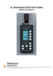
Download ULTRASOUND DETECTOR D980 OPERATING INSTRUCTIONS
Transcript
ULTRASOUND DETECTOR D980
OPERATING INSTRUCTIONS
Tallbacksvägen 51, SE-756 45 UPPSALA, Sweden Phone:+46 1830 3880 Fax :+46 1830 3840 e-mail: [email protected] Internet : www.batsound.com
2
Guarantee
This product is guaranteed against defects in material and workmanship for a period of one year from
the date of purchase. In order for the guarantee to be granted, a proof of purchase (normally the
original invoice/receipt) is required and the serial number label must not be removed from the product.
Pettersson Elektronik will repair or replace the product if it proves to be defective during the guarantee
period, provided it is returned to us. No other guarantee is expressed or implied. Pettersson Elektronik
assumes no responsibility for consequential damages of any kind.
The guarantee covers none of the following:
1. Damage to the product resulting from abuse and misuse, including but not limited to (a) the failure
to use this product for its normal purpose or in accordance with Pettersson Elektronik’s instructions on
the proper use and maintenance of this product and (b) the installation or the use of this product in a
manner inconsistent with the technical or safety standards in force in the country where the product is
used.
2. Damage to the product resulting from non-authorized modifications made to the product.
3. Repairs done by non-authorized technicians.
4. Accidents or similar causes beyond the control of Pettersson Elektronik, including but not limited to
lightning, water, fire and public disturbances.
D940 Ultrasound detector.
The D940 ultrasound detector is identical to the D980 detector, except that it does not have a time
expansion system. Hence, this manual also covers the D940 if all references to the time expansion
system are disregarded.
© Pettersson Elektronik AB, 2001
3
INTRODUCTION
The ultrasound detector D980 is an easy-to-handle and very powerful instrument for conversion of
ultrasound to audible sound. It is primarily intended for studying bats and other animals emitting
ultrasound. The detector has three independent ultrasound conversion systems; a heterodyne system, a
frequency division and a time expansion system. The detector is equipped with a digital display to
provide very accurate readings of the tuned frequency in heterodyne mode.
Before using the detector, please read the following information carefully! Further information on
the identification of different bat species using ultrasound detectors may be found in the literature (e.g.
Barataud: The inaudible world or Russ: The bats of Britain and Ireland, available from Pettersson
Elektronik).
The D980 transforms ultrasound in the range 10 - 200 kHz (the time expansion system: 10 – 150 kHz)
into the audible frequency range. Although the main application for the D980 is studying bioacoustic
ultrasound (bats, rodents, bush crickets etc.), the detector can be used in many other situations where
detection of ultrasound is involved (ultrasonic intruder systems, leaks in pressurized systems, corona
discharges etc.).
GETTING STARTED
The detector is powered from two 9 V batteries. A set of alkaline batteries will last for appr. 12 hours.
Remove the battery compartment lid, make sure the ON/OFF switch is in the OFF position and insert
two new batteries. Please note the polarity and make sure the detector’s battery connector snaps firmly
into position over the corresponding connector of the battery. Then turn on the detector by setting the
ON/OFF switch located next to the microphone in the ON position. The LCD display now shows the
tuned frequency (heterodyne system only!). To test the basic operation modes of the detector, please
perform the following steps.
Connect a set of stereo headphones to the PHONES jack.
Set both PHONES switches (LEFT and RIGHT) to the “H” (heterodyne ) position. Set the HF GAIN
control to maximum sensitivity (turn it fully counter-clockwise) and adjust the VOLUME control so
that a weak noise is heard in the headphones. Set the SCANNER CONTROLS “AUTO/MAN” switch
in the MAN position. Remove the red plastic protection cap from the microphone by gently pulling it
off the microphone. You should avoid touching the microphone membrane. Then turn the large
frequency knob to give a display reading of approximately 20 kHz and gently snap your fingers near
the microphone. A scraping sound should then be heard in the headphones. Another good ultrasound
source is a jingling bunch of keys.
The frequency control works in the following way. The display shows the center of the frequency
range (approximately 10 kHz wide), to be transformed. If the control is set to 30 kHz, you can listen to
ultrasonic frequencies between approximately 25 and 35 kHz.
Repeat the “finger-snapping” exercise while tuning the frequency control from 10 kHz and upwards.
Note how the level of the sound changes as the tuned frequency increases. This depends on the
spectral composition of the ultrasound, most of the energy in the signal is contained in the lower
frequency range.
The heterodyne system can also be used in an automatically scanning mode. For more information
about this mode, please refer to the section about the heterodyne system.
4
Next, let’s have a look at the frequency division system. The frequency division system is very easy
to use, since the detector will cover the full ultrasonic range without having to adjust the frequency
control. Set the two PHONES switches to the FD (frequency division) position and the 10/20 switch
(located below the PHONES jack) to the 10 position. In order to change the setting of the 10/20
switch, a pencil or similar pointed object should be used. The switch was deliberately positioned this
way, to avoid accidentally changing the setting.
To test the frequency division system, please repeat the test you performed on the heterodyne system
above.
Finally, let’s check out the time expansion system. The time expansion system is similar to recording
a sound on a tape recorder and then replaying the recorded signal at slower speed. In the detector, the
signal is stored in a digital memory. The D980 allows recording of signals up to 3 seconds or 12
seconds of length depending on the size of the memory. The 12 seconds version has a switch, by
means of which the recording time can be selected either 3 or 12 seconds. If you have this version, set
the switch to 3 seconds.
Push the TE START switch once and set both of the PHONES switches to the TE (time expansion)
position and the TRIG LEVEL maximum clockwise. Push the TE START switch again to start
recording into the digital memory. Nothing is heard in the headphones at this time. Snap your fingers
near the microphone for a few seconds and then push the TE STOP switch to interrupt the recording.
Immediately after pushing the TE STOP switch, the detector starts to replay the recorded signal at a
tenth of the original speed. Hence, replaying the 3 seconds sequence once will take 30 seconds. The
detector will remain in this mode and replay the recorded sequence in an end-less loop fashion until
the TE START button is pushed again.
There are also other ways to make the detector start and stop recording into the time expansion
memory by itself. Please refer to the section about the time expansion system for more information
about this.
After using the detector, please put the microphone protection cap back to avoid damaging the
sensitive microphone membrane.
Many electronic devices such as TV sets, computers and electronic watches also emit ultrasound. Such
ultrasound sources can be handy to test the detector, but may also cause undesired interference.
If you encounter any problems during the test of the detector, please refer to the Trouble -shooting
section.
THE ULTRASOUND CONVERSION SYSTEMS
a) The heterodyne system
There are several different principles to convert ultrasound into audible sound. As mentioned above,
one of the systems in the D980 is based on the heterodyne principle. This technique means that a
limited frequency range is selected for conversion into the audible range. Obviously, this also means
that only a small fraction of the wide-band noise will be made audible at each time, so the audible
noise level is low in a heterodyne detector. Hence, it is possible to detect very weak signals with this
system.
The heterodyne system in the D980 can be used either in the normal mode, which requires manually
tuning the frequency control, or in an automatically scanning mode. The AUTO/MAN switch in the
SCANNER CONTROLS section is used to change the mode. The manual mode is described first.
5
If the frequency control is adjusted to give a display reading of 30 kHz, the range from appr. 25 to 35
kHz will be transformed. This is illustrated in the figure below.
Let’s assume an ultrasonic signal with constant frequency is emitted. The frequency of the
transformed signal (i.e. the signal heard in the headphones) equals the difference between the
frequency of the ultrasound and the tuned (displayed) frequency. In this case, when the detector is
tuned to 30 kHz, this means that an ultrasound of either 31 or 29 kHz will be transformed into 1 kHz.
When the frequency control of the D980 is turned from low frequencies to higher, a high-pitched tone
will be heard in the loudspeaker when the frequency setting is appr. 5 kHz lower than the frequency of
the ultrasound source. The closer the tuned frequency comes to the ultrasound's frequency, the lower
the frequency of the loudspeaker tone gets. When both frequencies are identical the resulting output
frequency becomes zero, i.e. nothing is heard in the headphones. If you continue to turn the frequency
control towards higher frequencies, a tone will again be heard in the loudspeaker, however this time
the frequency will increase as the tuned frequency increases. By tuning the frequency control up and
down it is possible to locate the frequency resulting in a zero Hz output frequency (the tuned
frequency then equals the frequency of the ultrasound).
NOTE: The example above is only intended to illustrate the heterodyne principle. Constant frequency
sounds are very rare in practice, so in most cases you will only be able to get an approximate measure
of the signal frequency.
In the scanning mode (AUTO/MAN switch in the SCANNER CONTROLS section set to AUTO), the
detector rapidly scans a selected frequency range up and down, searching for sounds. If a sound is
detected, the scanning is inhibited for a few seconds, allowing the user to read the display. The
scanning range is determined by the settings of the frequency control (the large knob also used to tune
the heterodyne system) and the SCAN RANGE control. The frequency control determines the lower
frequency limit while the SCAN RANGE control determines the width of the scanning range.
To set the scanning range, adjust the two controls mentioned above, while at the same time noting the
frequencies shown on the display. The scanning is made quite rapidly, so it is necessary to observe the
display carefully to determine the obtained scanning range.
Next, the amplitude threshold should be adjusted. As was mentioned above, when a sound is detected,
the scanning is inhibited. The LEVEL control is used to set the level, above which the sound is
considered to be “detected”. Turning the control clockwise decreases the threshold level.
When a sound is detected, the scanning stops for a few seconds and the “LOCKED” indicator lights
up. The display can be read, to obtain an approximate value of the frequency of the signal. During the
“scanning inhibit” period, a slight frequency drift may occur.
6
b) The frequency division system
Frequency division means that the frequency of the ultrasound is changed with a constant factor of 10
or 20 depending on the setting of the frequency division switch (located on the right-hand side of the
detector, below the PHONES jack). If the frequency divisio n switch is set to 10, a frequency of 40
kHz becomes 4 kHz, a frequency of 50 kHz becomes 5 kHz etc. Using this system, any activity over
the entire frequency range 10 – 200 kHz can be constantly monitored. Furthermore, the shape of the
transformed signal closely follows that of the original signal, as shown in the figure below.
The frequency division is obtained by counting the number of “zero-crossings” made by the original
signal. An output signal with one zero-crossing for each ten (twenty) zero-crossings of the original
signal is then generated. Normally, this gives an output signal with a frequency of one tenth of the
original frequency. However, if the original signal has a strong harmonic component, extra zerocrossings will occur and the resulting output frequency will be higher than that corresponding to the
fundamental frequency (the system transforms the harmonic frequency component, not the
fundamental). This situation is relatively uncommon. Nevertheless, it is important to remember that it
occasionally may occur.
7
c) The time expansion system
This technique is similar to recording a sound on a tape recorder and then replaying the tape at a
reduced speed. However, in the D980 the signal is not stored on a magnetic tape but in a digital
memory. The time expansion principle is unique in the sense that it is the only ultrasound conversion
system that retains virtually all characteristics of the original signal, so time expanded signals are well
suited for many forms of advanced signal analysis (e.g. with our sound analysis software package
BatSound). The time expansion factor is 10 on the standard version of the D980 (a special version
with selectable time expansion factor 10 or 20 is also available). The maximum recording time is 3
seconds (12 seconds as option). Please note that the text “3 SEC 12 SEC” on the front panel label, is
present on both the 3 seconds and 12 seconds model. It should be disregarded on the 3 seconds model.
The time expansion system can be used either in manual or automatic mode. In the manual mode, the
user initiates the sound capture by pushing a switch, while the detector does this automatically in the
automatic mode. The automatic mode is adapted for the 3 seconds version of the D980, i.e. the
detector will be automatically “armed” again after replaying 30 seconds of time expanded sound.
To use the automatic mode, set the AUTO/MAN switch (located to the left of the OVERLOAD
indicator) to the AUTO position and set the TRIG LEVEL control to a suitable level. Perform a few
test recordings to determine a suitable setting. In the automatic mode, the recently made recording is
replayed once and then the detector waits for the next signal to record. If the TRIG LEVEL is set
maximum counter-clockwise, the detector will be triggered from very weak signals and this means
that in practice the detector will make a new recording immediately after replaying the previous
recording.
To use the manual mode, set the AUTO/MAN switch (located to the left of the OVERLOAD
indicator) to the MAN position. The recording is initiated by pushing the TE START switch. This
places the detector in the “armed” mode. The setting of the TRIG LEVEL determines when the
recording is interrupted. Three sub-modes are available:
i) TRIG LEVEL is set maximum counter-clockwise. In this case, the recording is interrupted
“immediately” - or rather as soon as a preset time has elapsed. This delay is to make sure that the
time expansion memory will be filled. Using this mode, a recording of 3 (12) seconds will be
made starting from when the TE START button was pushed.
ii) TRIG LEVEL is set to an intermediate position. In this case, the recording is interrupted
shortly after the signal exceeds the level determined by the TRIG LEVEL. In order not to miss
the beginning of the signal, a “pre-trigger” time of ca. 1 second is included here (see the figure
below).
8
iii) TRIG LEVEL is set maximum clockwise. In this case, the recording is started by pushing the
TE START button and stopped by pushing the TE STOP button, i.e. the user has full control over
the recording process. This mode is often the most useful for making recordings manually. Using
this mode, a recording of the last 3 (12) seconds prior to pushing the TE STOP button will be
made.
NOTE: Immediately afte r turning the power on, the time expansion memory contains a random, highlevel signal. In order to protect your hearing, always decrease the headphones volume prior to turning
the power on, and then press the TE START button to remove the initial signal f rom the memory.
GENERAL TECHNICAL DESCRIPTION
The batteries
The detector is powered from two 9V batteries. Alkaline types are recommended and will last for
approximately 12 hours. Frequent use of the display light (the light switch is located to the left of the
frequency control) results in shorter battery life-time. When the battery voltage has decreased to about
7 volts, the BATTERY LOW indicator will light up. One failing battery results in a moderate light,
while two failing batteries makes the indicator light more intensively. The detector can be used even if
the BATTERY LOW indicator is on. The sensitivity is lower and the risk for signal distortion
increases, though.
The microphone
The microphone is a solid-dielectric capacitance microphone, with a built-in preamplifier. This type of
microphone requires a polarizing voltage (about 200 volts), which is generated by a DC/DC converter
in the detector. This voltage is present at the microphone socket. To remove the microphone from the
detector, unscrew the grooved, green ring and gently pull the microphone off the socket. When
attaching the microphone again, make sure the ring is properly tightened. If the microphone membrane
has been worn or punctured, it may be necessary to replace it. The mic rophone capsule (the upper part
of the microphone with the membrane) is replaceable and is available as a spare part. To remove the
microphone capsule, unscrew the lock screw (see figure below) slightly with a suitable screwdriver
and pull the microphone capsule from the microphone housing. Do not unscrew any other screws on
the microphone – this may cause damage to the microphone and/or the microphone capsule!
Microphone capsule
lock screw
9
NOTE: The microphone membrane is easy to damage. At all times, touching the microphone
membrane should be avoided! If the microphone membrane has been punctured, electrical discharges
may occur. Although the energy stored in the microphone capsule is very limited, the detector should
not be used in areas with explosive gas.
The headphones and PHONES switches
Any set of stereo headphones with a standard 3.5 mm stereo plug and an impedance of 4 ohms or
more, can be used. The headphones should be connected to the PHONES jack on the right-hand side
of the detector. The output level to the headphones is adjusted with the VOLUME control. The setting
of the PHONES switches determine which system is fed to the headphones. It is possible to listen to
two of the three systems simultaneously. The setting of the PHONES switches and the VOLUME
control do not affect the tape recorder outputs (FREQ DIV, HET and TIME EXP).
The HF GAIN and OVERLOAD indicator
The HF GAIN control is located on the left-hand side of the microphone. Maximum sensitivity is
obtained when the knob is turned maximum counter-clockwise. If the ultrasound to be monitored is
too loud, the input stage of the detector will be overloaded. This is indicated by the flashing of the
OVERLOAD indicator. Overloading does not cause any damage to the detector, but the signals
processed by the detector will become distorted. Hence, it is suggested that the HF gain control be
adjusted if the OVERLOAD indicator flashes frequently, particularly if the transformed signals will be
used for sound analysis.
The outputs
The output jacks are all located on the right-hand side of the detector. The transformed sounds are
monitored through headphones connected to the PHONES jack (3.5 mm stereo plug). A tape recorder
can be connected to the “FREQ DIV”, “HET” or “TIME EXP” jacks (phono jacks) to make recordings
of the transformed sounds or to the “HF” jack to record the unaltered signal from the microphone
signal. Typically, the HF output is used to record the original high-frequency signal on a device
capable of recording such high frequencies (an instrumentation tape recorder or a computer with a
high-speed sound card). In order to facilitate recording of spoken comments, there is also a
“COMMENT” push-button. Pressing this switch, makes the microphone signal temporarily available
at the HET output.
If the input impedance of the tape recorder is very low (lower than ca.5 kohms), the signal levels in the
detector will be decreased, resulting in a weaker output to the headphones. Any tape recorder
connected to the TAPE output should be battery powered. The maximum length of any connected
cable is 1 meter.
10
TROUBLE-SHOOTING
The D980 is a very carefully designed instrument. If, however, a malfunction would occur, it is hoped
that this check-list will help to correct the fault.
Symptom
Possible cause and remedy
No sound, no light from LED’s.
Dead batteries. Replace batteries.
No sound/weak sound.
HF GAIN or VOLUME control is set too low.
Adjust the controls.
Defective headphones. Replace headphones.
Low battery voltage. Replace batteries.
Damaged microphone capsule. Replace capsule.
Capsule not properly attached. Check contact
spring under microphone capsule.
Sudden crackles and/or noise.
Damaged microphone capsule. See above.
Capsule not properly attached. See above.
Microphone/detector has been exposed to high
humidity. Allow the system to dry.
Acoustic feedback.
Microphone too close to the headphones. Direct
the microphone away from the headphones.
Reduce the headphones volume.
No sound, one or both LED’s flashes.
One battery has low voltage or is incorrectly
inserted. Check battery voltage and battery
connectors. Adjust/clean connectors if necessary.
The heterodyne frequency control does not work
after turning on the power.
The scanner AUTO/MAN switch is in the AUTO
position. Change it to the MAN position and then
back to AUTO again.
Poor tonal quality from the frequency division
system
The 10/20 switch is not properly set. Make sure
that the switch is pushed all the way to its end
position.
NOTE: There are no user-serviceable parts inside the detector. Always refer servicing to
qualified service personnel.
11
Technical specifications
Type:
Frequency range:
Display accuracy:
Headphones output:
Audio outputs:
High frequency output
Heterodyne, frequency division (10 or 20) and time expansion (x10)
10 - 200 kHz (frequency division and heterodyne)
10 - 150 kHz (time expansion)
+/- 0.2 kHz
3.5 mm stereo jack, load impedance 4 ohms or greater
3 x phono jacks for tape recorder (appr 500 mV rms max/4 kohm)
Phono jack (appr 500 mV rms max/1 kohm)
Time expansion system:
Sampling frequency:
Memory size:
Resolution:
Storage time:
Time expansion factor:
Pre-trigger:
350 kHz
1M x 8 bits (12 seconds version: 4M x 8 bits)
8 bits
3 seconds (selectable 3/12 seconds on 12 seconds version)
10 (selectable 10 or 20 on request)
1 second
Batteries:
Quiescent current:
Size:
Weight:
Comment switch:
Miscellaneous:
2 x IEC 6LF22 (9V)
39 mA typ. including microphone
170 x 100 x 65 mm incl. knobs etc.
600 g. including battery
Yes
Overload indicator, adjustable input gain
Using the detector in intense electromagnetic fields may cause interference and/or temporary signal loss.


