1
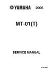
SV650SK 1 ('01-MODEL)
This manual describes service data, service specifications and servicing procedures which
differ from those of the SV650K1 ('01-MODEL) .
NOTE:
• Any differences between the SV650K1 ('01-MODEL) and SV650SK1 ('01-MODEL) in
specifications and service data are clearly indicated with an asterisk mark (*) .
• Please refer to the SV650 Service Manual for details which are not given in this manual .
CONTENTS
INFORMATION LABELS
SPECIFICATIONS
PERIODIC MAINTENANCE
BRAKE
CHASSIS BOLT AND NUT
EXTERIOR PARTS
CONSTRUCTION
COWLING
FRONT FORK
REMOVAL
REMOUNTING
STEERING
CONSTRUCTION
HANDLEBARS
STEERING REMOVAL
STEERING INSTALLATION FRONT BRAKE
CONSTRUCTION
BRAKE FLUID REPLACEMENT
FRONT MASTER CYLINDER
SPEEDOMETER
REMOVAL
CONSTRUCTION
INSPECTION
HEADLIGHT
BULB REPLACEMENT
WIRING DIAGRAM
WIRE HARNESS ROUTING
CABLE ROUTING
FRONT BRAKE HOSE ROUTING
COWLING AND SEAT TAIL COVER SET-UP SERVICE DATA
PRIMARY DRIVEN GEAR CONSTRUCTION
2
3
5
5
6
8
8
9
11
11
12
13
13
14
17
18
19
19
20
21
26
26
27
27
30
30
31
32
34
35
36
37
47
12-1
12-2
SV650SK1 ('01-MODEL)
•
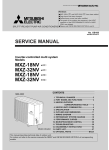
INFORMATION LABELS
1
Noise label
2
Information label
3 Vacuum hose routing label (For E-33)
4 Manual notice label
5 Frame caution plate
6 Warning screen label
7 Warning steering label
8 Tire pressure label
9
10
Warning safety label
Safety plate
SV650SK1 ('01-MODEL)
0
SPECIFICATIONS
DIMENSIONS AND DRY MASS
Overall length
Overall width
Overall height
Wheelbase
Ground clearnce
Seat height
Dry mass
ENGINE
Type
Number of cylinders Tappet clearance, IN
EX
Bore
Stroke
Piston displacement
Compression ratio
Carburetor
Air cleaner
Starter system
Lubrication system
TRANSMISSION
Clutch
Transmission
Gearshift pattern
Primary reduction ratio Gear ratios, Low
2nd
3rd
4th
5th
Top
Final reduction ratio
Drive chain
* 2 045 mm (80 .5 in)
*
740 mm (29 .1 in)
* 1 130 mm (44 .5 in)
* 1 420 mm (55 .9 in)
140 mm ( 5 .5 in)
805 mm (31 .7 in)
*
169 kg
(372 Ibs)
Four-stroke, Liquid-cooled, DOHC, TSCC,
90-degree V-twin
2
0 .10 - 0 .20 mm (0 .004 - 0 .008 in)
0 .20 - 0 .30 mm (0 .008 - 0 .012 in)
81 .0 mm (3 .189 in)
62 .6 mm (2 .465 in)
645 cm 3 (39 .4 cu . in)
11 .5 :1
MIKUNI BDSR39 x 2
Non-woven fabric element
Electric starter
Wet sump
Wet multi-plate type
6-speed constant, mesh
1-down, 5-up
2 .088 (71/34)
2 .461 (32/13)
1 .777 (32/18)
1 .380 (29/21)
1 .125 (27/24)
0 .961 (25/26)
0 .851 (23/27)
* 2 .933 (44/15)
* D.I .D 525 V9, 108 links
12-3
12-4
SV650SK1 ('01-MODEL)
•
CHASSIS
Front suspension
Telescopic, coil spring, oil damped
Rear suspension
Link type system, gas/oil damped, coil spring
Front fork stroke
130 mm (5 .1 in)
Rear wheel travel
125 mm (4 .9 in)
Steering angle
* 30° (right & left)
Caster
25°
Trail
100 mm (3 .94 in)
Turning radius
* 3 .1 m (10 .2 ft)
Front brake
Disc brake, twin hydraulically operated
Rear brake
Disc brake, hydraulically operated
Front tire size
120/60 ZR17 (55 W), tubeless
Rear tire size . . . . . . . . . . . . . . . . . . . . . . . . . . . . . . . . . . . . . . . . . . . . . . . . . . . . . . . . . . . . . . . . . 160/60 ZR17 (69 W), tubeless
ELECTRICAL
Ignition type Electronic ignition (Transistorized)
Ignition timing
5° B .T D .C . at 1 300 r/min
Spark plug NGK CR8E, DENSO U24ESR-N
Battery
12V 36 .0 kC(10 Ah)/10HR
Generator
Three-phase A .C . Generator
Main fuse
30A
Fuse
15/15/15/10/10A
Headlight
* 12V 45/45W x 2
Turn signal light 12V 21W
Brake light/Taillight
12V 21/5W x 2
License plate light 12V 5W
Speedometer light
* 12V 0 .84W x 3
Neutral indicator light 12V 1 .7W
High beam indicator light
12V 1 .7W
Turn signal indicator light
* 12V 3W
Oil pressure indicator light . . . . . . . . . . . . . . . . . . . . . . . . . . . . . . . . . . . . . . . . . . . . 12V 1 .7W
Fuel level indicator light
12V 1 .7W
Water temp . indicator light
LED
CAPACITIES
Fuel tank, including reserve Engine oil, oil change
with filter change
overhaul
16 .0 L (4 .2/3 .5 US/Imp gal)E-03
15 .0 L (4 .0/3 .3 US/Imp gal)E-33
2 300 ml (2 .4/2 .0 US/Imp qt)
2 400 ml (2 .5/2 .1 US/Imp qt)
2 700 ml (2 .9/2 .4 US/Imp qt)
1 600 ml (1 .7/1 .4 US/Imp qt)
•
These specifications are subject to change without notice .
0
•
SV650SK1 ('01-MODEL)
PERIODIC MAINTENANCE
BRAKE
(BRAKE)
Inspect initially at 1 000 km (600 miles, 1 month) and every 6 000 km (4 000 miles, 6 months) thereafter.
(BRAKE HOSE AND BRAKE FLUID)
Inspect every 6 000 km (4 000 miles, 6 months) . Replace
hoses every 4 years . Replace fluid every 2 years .
BRAKE FLUID LEVEL CHECK
• Keep the motorcycle upright and place the handlebars straight .
• Remove the rear seat . (CLF 6-3 of the SV650 Service Manual)
• Check the brake fluid level by observing the lower limit lines on
the front and rear brake fluid reservoirs .
• When the level is below the lower limit line, replenish with brake
fluid that meets the following specification .
BF
Specification and Classification : DOT 4
A WARNING
• The brake system of this motorcycle is filled with a
glycol-based brake fluid . Do not use or mix different
types of fluid such as silicone-based and petroleumbased fluids . Do not use any brake fluid taken from
old, used or unsealed containers . Never re-use brake
fluid left over from the last servicing or stored for a
long period of time .
• Brake fluid, if it leaks, will interfere with safe running
and immediately discolor painted surfaces . Check the
brake hoses and hose joints for cracks and oil leakage
before riding .
12-5
12-6
SV650SK 1 ('01-MODEL)
CHASSIS BOLT AND NUT
Tighten initially at 1 000 km (600 miles, 1 month) and every 6 000 km (4 000 miles, 6 months)
thereafter.
Check that all chassis bolts and nuts are tightened to their specified torque . (Refer to the next page for the
locations of the following nuts and bolts on the motorcycle .)
Item
10 Steering stem head nut
02 Front fork upper clamp bolt
(3 Front fork lower clamp bolt
® Front fork cap bolt
~5 Front axle
© Front axle pinch bolt
~7 Handlebar set bolt
® Handlebar clamp bolt
O Clutch lever holder mounting bolt
0 Front brake master cylinder mounting bolt
11 Front brake caliper mounting bolt
1© Brake hose union bolt
13 Air bleeder valve
14 Brake disc bolt (Front and Rear)
15 Rear brake caliper mounting bolt
16 Rear brake caliper housing bolt
17 Rear brake master cylinder mounting bolt
1s Rear brake master cylinder rod lock nut
19 Front footrest bracket mounting bolt
2o Front footrest bolt
21 Swingarm pivot shaft nut
22 Swingarm pivot shaft lock nut
23 Swingarm pivot shaft
24 Torque link nut (Front & Rear)
25 Rear shock absorber mounting nut
© Rear shock absorber mounting bolt
2® Cushion lever mounting nut
28 Cushion rod mounting nut
29 Rear axle nut
30 Rear sprocket nut
N-m
65
23
23
23
65
23
10
23
10
10
39
23
7 .5
23
26
30
10
18
23
39
kgf-m
6 .5
2 .3
2 .3
2 .3
6 .5
2 .3
1 .0
2 .3
1 .0
1 .0
3 .9
2 .3
0 .75
2 .3
2 .6
3 .0
1 .0
1 .8
2 .3
3 .9
100
10 .0
90
15
35
50
50
78
78
65
60
9 .0
1 .5
3 .5
5 .0
5 .0
7 .8
7 .8
6 .5
6 .0
lb-ft
47 .0
16 .5
16 .5
16 .5
47 .0
16 .5
7 .0
16 .5
7 .0
7 .0
28 .0
16 .5
5 .5
16 .5
19 .0
21 .5
7 .0
13 .0
16 .5
28 .0
72 .5
65 .0
11 .0
25 .5
36 .0
36 .0
56 .5
56 .5
47 .0
43 .5
•
•
_
0
0
SV650SK1 ('01-MODEL)
12-7
12-8
SV650SK1 ('01-MODEL)
•
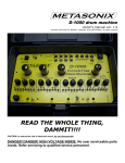
EXTERIOR PARTS
CONSTRUCTION
m
•
•
T Wind screen
OO Upper panel
03 Side cowling
® Center cowling
E Cowling brace
© Front side cover
07 Front fender
® Front seat
09 Rear seat
10 Seat tail cover
SV650SK 1 ('01-MODEL)
COWLING
• Remove the left and right upper panels .
• Remove the rear view mirrors .
• Remove the wind screen .
• Remove the left and right side cowling .
• Remove the turn signal lights .
12-9
12-10
SV650SK1 ('01-MODEL)
• Remove the center cowling .
• Remove the combination meter panel .
• Remove the headlight assembly .
• Remove the combination meter .
• Remove the cowling brace .
• Remount the cowling in the reverse order of removal .
SV650SK1 ('01-MODEL)
FRONT FORK
REMOVAL
• Remove the brake hose clamp bolts and speed sensor clamp
0
bolt .
• Remove the front brake calipers . (fr' 6-48 of the SV650 Service Manual)
• Remove the front wheel .
(ci 6-7 of the SV650 Service
Manual)
• Remove the front fender .
(r r
6-3 of the SV650 Service
Manual)
• Loosen the front fork upper clamp bolt 90 .
NOTE:
Slightly loosen the front fork cap bolt before loosening the lower
clamp bolts to facilitate later disassembly.
• Loosen the handlebar clamp bolt Z2 .
• Loosen the handlebar set bolt ® .
• Loosen the front fork lower clamp bolts ® .
NOTE:
Be careful not to drop the front fork when loosening the bolts .
• Remove the front forks .
12- 1 1
12-12
SV650SK1 ('01-MODEL)
0
REMOUNTING
• Align the upper surface AO of the inner tube with the upper
surface © of the steering stem upper bracket .
0
• Tighten the front fork lower clamp bolts
D
to the specified
torque .
• Front fork lower clamp bolt : 23 N-m (2 .3 kgf-m, 16 .5 lb-ft)
• Tighten the handlebar set bolt 20 to the specified torque .
• Handlebar set bot : 10 N-m (1 .0 kgf-m, 7 .0 lb-ft)
0
0
• Tighten the handlebar clamp bolt 03 to the specified torque .
• Tighten the front fork cap bolt .
• Tighten the front fork upper clamp bolt ® .
• Handlebar clamp bolt : 23 N-rn (2 .3 kgf-m, 16 .5 lb-ft)
Front fork cap bolt : 23 N-m (2 .3 kgf-m, 16 .5 lb-ft)
Front fork upper clamp bolt : 23 N-m (2 .3 kgf-m, 16 .5 lb-ft)
A
s
• Install the front fender. (F--T 6-3 of the SV650 Service Manual)
• Install the front wheel . (f1 6-9 of the SV650 Service Manual)
• Install the brake calipers . (r7 6-50 of the SV650 Service
Manual)
41
SV650SK1 ('01-MODEL)
STEERING
CONSTRUCTION
D Steering stem upper bracket
©O Steering stem nut
Ds Dust seal
® Steering stem upper bearing
65 Steering stem lower bearing
© Steering stem
®7 Handlebar
® Handlebar balancer
A
Steering stem head nut
© Front fork upper clamp bolt
© Front fork lower clamp bolt
(a Handlebar clamp bolt
®E Handlebar set bolt
0
40
ITEM
N-m
kgf-m
lb-ft
DA
65
6 .5
47 .0
8©©
23
2 .3
16 .5
E
10
1 .0
7 .0
1 2 -13
1 2 -14
SV650SK1 ('01-MODEL)
HANDLEBARS
REMOVAL
• Remove the following items from the left handlebar .
1O Left handlebar switch
(2 Handlebar balancer
©3 Grip rubber
® Clutch cable/Clutch lever holder
• Remove the following items from the right handlebar .
O5 Right handlebar switch
© Throttle cables
(7 Handlebar balancer
® Throttle grip
O Front brake master cylinder/reservoir
A CAUTION
Do not turn the front brake master cylinder upside down .
• Lift and support the fuel tank . (Cz 4-4 of the SV650 Service
Manual)
• Remove the air cleaner box . (F-7 3-4 of the SV650 Service
Manual)
• Disconnect the ignition switch lead wire coupler .
• Remove the handlebar set bolts .
• Remove the steering stem upper bracket .
• Loosen the handlebar clamp bolts and remove the handle bars .
0
SV650SK1 ('01-MODEL)
INSTALLATION
• Install the handlebars to the front forks .
NOTE :
After installing the steering stem upper bracket, tighten the handlebar set bolts and the clamp bolts .
• Tighten the steering stem head nut and the front fork upper
clamp bolts to the specified torque .
• Steering stem head nut : 65 N-m (6 .5 kgf-m, 47 .0 lb-ft)
Front fork upper clamp bolt: 23 N-m (2 .3 kgf . m,16 .5 lb-ft)
• Connect the ignition switch lead wire coupler .
• Tighten the handlebar clamp bolts and the set bolts to the specified torque .
• Handlebar clamp bolt : 23 N-m (2 .3 kgf-m, 16 .5 Ib-ft)
Handlebar set bolt : 10 N-m (1 .0 kgf-m, 7 .0 Ib-ft)
• Install the following items to the right handlebar .
1~ Front brake master cylinder/reservoir
02 Throttle grip
O3 Handlebar balancer
® Throttle cables
($ Right handlebar switch
NOTE:
• Apply grease to the throttle cable and the cable drum .
99000-25010 : SUZUKI SUPER GREASE "A"
• Align the portion OO of the right handlebar switch with the hole
© of the handlebar.
• Adjust the throttle cable play. (c--r 2-16 of the SV650 Service
Manual)
12-15
12-16
SV650SK1 ('01-MODEL)
• Tighten the front brake master cylinder mounting bolts to the
specified torque .
NOTE:
Align the front brake master cylinder holder's matching surface
with the punched mark on the handlebar and tighten the upper
mounting bolt first, then lower one.
• Front brake master cylinder mounting bolt : 10 N-m
(1 .0 kgf-m, 7 .0 lb-ft)
• Install the following items to the left handlebar .
• Clutch cable/Clutch lever holder
02 Grip rubber
O3 Handlebar balancer
• Left handlebar switch
NOTE:
* Align the portion O of the left handlebar switch with the hole
• of the handlebar.
* Lightly adhere the grip rubber to the handlebar .
• Tighten the clutch holder mounting bolt to the specified torque .
NOTE:
Align the clutch holder's matching surface with the punched mark
on the handlebar.
• Clutch holder mounting bolt : 10 N-m (1 .0 kgf-m, 7 .0 lb-ft)
1
4
SV650SK1 ('01-MODEL)
STEERING REMOVAL
• Remove the following items .
Cowling (['-7- 12-9)
Front wheel (T7 6-7 of the SV650 Service Manual)
Handlebars (CI 12-14)
Front fork (["7 12-11)
Horn
i
NOTE :
Remove the horn with its bracket.
i
• Remove the front brake assembly by removing the brake hose
joint .
A CAUTION
Do not turn the front brake master cylinder upside down .
L
• Remove the steering stem nut using the special tool .
09940-14911 : Steering stem nut wrench
4-
NOTE:
Hold the steering stem lower bracket to prevent it from falling .
• Remove the steering stem .
L
• Remove the dust seal, the inner race and the bearing .
4-
12-17
12-18
SV650SK1 ('01-MODEL)
STEERING INSTALLATION
• Apply grease to the bearings and lip of dust seal .
99000-25010 : SUZUKI SUPER GREASE "A"
• Install the lower bearing to the steering stem lower bracket .
• Install the upper bearing, bearing inner race and dust seal .
• Tighten the steering stem nut to the specified torque with the
special tools .
..
09940-14911 : Steering stem nut wrench
0 Steering stem nut : 45 N-m (4 .5 kgf-m, 32 .5 Ib-ft)
• Turn the steering stem lower bracket about five or six times to
the left and right so that the angular ball bearings will be seated
properly.
• Loosen the stem nut by 1/4 - 1/2 turn .
NOTE:
This adjustment will vary from motorcycle to motorcycle .
• Install the following items .
• Front brake assembly (F-77 12-35)
• Horn
• Front fork (1 r 12-12)
• Handlebars (f
12-15)
• Front wheel (C-r 6-9 of the SV650 Service Manual)
• Cowling
00
SV650SK1 ('01-MODEL)
FRONT BRAKE
CONSTRUCTION
J) Master cylinder reservoir cap
• Diaphragm
Dust boot
• Piston/cup set
~5 Master cylinder clamp
• Master cylinder
(7 Brake hose #1
© Brake hose joint
~9 Brake hose #2 (R)
1o Brake hose #2 (L)
11 Brake pads
12 Brake pad mounting pin
13 Clip
14 Spring
© Dust seal
16 Piston seal
17 Brake caliper pistons
9 Brake caliper
19 Brake caliper holder
4
j
-W
Master cylinder clamp bolt
© Brake hose union bolt
© Air bleeder valve
0 Brake caliper mounting bolt
0,
e
r1
M
ITEM
N •m
kgf •m
lb-ft
(A
10
1 .0
7 .0
©
23
2 .3
16 .5
©
7 .5
0 .75
5 .5
0
39
3 .9
28 .0
r
15
12-19
12-20
A
SV650SK1 ('01-MODEL)
WARNING
• This brake system is filled with an ethylene glycol-based DOT 4 brake fluid . Do not use or mix
different types of fluid, such as silicone-based or petroleum-based fluids .
• Do not use any brake fluid taken from old, used or unsealed containers . Never reuse brake fluid
left over from the last servicing or which has been stored for long periods of time .
• When storing brake fluid, seal the container completely and keep it away from children .
• When replenishing brake fluid, take care not to get dust into the fluid .
• When washing brake components, use new brake fluid . Never use cleaning solvent .
• A contaminated brake disc or brake pad reduces braking performance . Discard contaminated
pads and clean the disc with high quality brake cleaner or a neutral detergent .
A CAUTION
Handle brake fluid with care : the fluid reacts chemically with paint, plastics, rubber materials etc . .
BRAKE FLUID REPLACEMENT
• Place the motorcycle on a level surface and keep the handlebars straight .
• Remove the brake fluid reservoir cap and diaphragm by removing the cap stopper.
• Suck up the old brake fluid as much as possible .
• Fill the reservoir with new brake fluid .
Brake fluid type
Specification : DOT 4
• Connect a cleaner hose to the caliper air bleeder valve and
insert the other end of hose into a receptacle .
• Loosen the air bleeder valve and pump the brake lever until old
brake fluid flows out of the bleeder system .
• Close the caliper air bleeder valve and disconnect a clear hose .
Fill the reservoir with new brake fluid to the upper mark of the
reservoir.
A CAUTION
Bleed air from the brake system . (C7 2-24 of the SV650
Service Manual)
r
4
SV650SK1 ('01-MODEL)
FRONT MASTER CYLINDER
REMOVAL AND DISASSEMBLY
• Drain brake fluid . (C' 6-47 of the SV650 Service Manual)
• Disconnect the brake light switch lead wire .
• Place a rag underneath the brake hose union bolt on the master cylinder to catch any split brake fluid . Remove the brake
hose union bolt and disconnect the brake hose .
A CAUTION
Immediately wipe off any brake fluid contacting any part
of the motorcycle .The brake fluid reacts chemically with
paint, plastics and rubber materials, etc ., and will damage them severely.
• Remove the master cylinder with the reservoir .
t
• Remove the reservoir from the master cylinder .
'V
• Remove the brake lever and the brake light switch .
1-1
12-21
12-22
SV650SK1 ('01-MODEL)
• Remove the dust cover and the dust boot .
• Remove the circlips .
09900-06108 : Snap ring pliers
• Remove the brake hose connector, the O-ring, the piston/cup
set and the return spring .
SV650SK1 ('01-MODEL)
REASSEMBLY AND REMOUNTING
Reassemble the master cylinder in the reverse order of removal
and disassembly. Pay attention to the following points :
A CAUTION
• Wash the master cylinder components with fresh brake
fluid before reassembly. Never use cleaning solvent
or gasoline to wash them .
• Do not wipe the components with a rag .
• Apply brake fluid to the cylinder bore and all the component to be inserted into the bore .
• Install the piston/cup set into the master cylinder .
• Install the brake hose connector .
A CAUTION
Use a new O-ring to prevent the fluid leakage .
L
4r
• Install the circlips .
09900-06108 : Snap ring pliers
A CAUTION
The round edge side of the circlip must be against to
inside .
12-23
12-24
SV650SK1 ('01-MODEL)
• Install the dust cover and the dust boot .
• Install the brake lever and the brake light switch .
NOTE:
* Apply grease to the brake lever pivot bolt when installing .
99000-25010 : SUZUKI SUPER GREASE "A"
Align the projection on the brake light switch with the hole on
the master cylinder.
• Install the reservoir to the master cylinder .
• When remounting the brake master cylinder onto the handlebar, align the master cylinder holder's mating surface OO with
punched mark © on the handlebar and tighten the upper clamp
bolt first as shown .
• Front brake master cylinder mounting bolt : 10 N-m
(1 .0 kgf-m, 7 .0 lb-ft)
OF
• Install the brake hose . ([' -7 12-35)
• Tighten the brake hose union bolt to the specified torque .
• Brake hose union bolt : 23 N-m (2 .3 kgf . m, 16 .5 Ib-ft)
A CAUTION
Use new seal washers to prevent fluid leakage .
SV650SK1 ('01-MODEL)
• Connect the brake light switch lead wire .
A CAUTION
Bleed air from the brake system after reassembling the
2-24 of the SV650 Service Manual)
master cylinder . (f-
L
L
12-25
12-26
SV650SK1 ('01-MODEL)
SPEEDOMETER
REMOVAL
• Remove the side cowling (R), (L) and center cowling . (r7 12-9)
• Remove the meter panel by removing the screws .
-4
• Disconnect the speedometer coupler.
• Remove the nuts .
• Remove the speedometer .
BULB REPLACEMENT
• Remove the sockets .
• Remove the bulbs .
• Reassemble and remount the speedometer assy is the reverse
order of removal and disassembly .
4
SV650SK1 ('01-MODEL)
12-27
CONSTRUCTION
INSPECTION
Using the tester, check the continuity between terminals in the following diagram . If the continuity measured
is incorrect, remove and check the bulb .
If the bulb is failure, install the new bulb and check the continuity again . If the bulb is correct, replace the unit
with a new one .
~,gy Tester knob indication : Diode test (-W)
®
ITEM
®+ Probe of
tester to :
O Probe of
tester to:
TURN SIGNAL
1 , 12
FUEL
O2
O5 ©
NEUTRAL
OO
13
HI BEAM
~o
OIL
O
BATTERY
OO
IGNITION
D+
©
SPEED SENSOR ®
®
IGNITION COIL (SIGNAL)
©
FUEL LEVEL GAUGE B
©
FUEL LEVEL GAUGE A
©
OIL PRESSURE GAUGE
®
GROUND (POWER)
ILLUMINATION +®
1o
HIGH BEAM
O+
TURN (L)
O+
t2
TURN (R)
O+
13
NEUTRAL SWITCH
14
SPEED SENSOR (SIGNAL)
15
WATER TEMPERATURE SWITCH
6
GROUND (SIGNAL)
OO
OIL (LED)
©
OO
WATER TEMPERATURE
(LED)
O2
15
METER ILLUMINATION
©
12-28
SV650SK1 ('01-MODEL)
FUEL LEVEL INDICATOR LIGHT INSPECTION
4-4 of the SV650
Service Manual)
• Disconnect the oil pressure switch lead wire coupler .
• The fuel indicator light lights up for approx . 3 seconds after the
ignition switch is turned on then the indicator light should go
out .
• Disconnect the fuel level indicator switch lead wire coupler 1~ .
• Connect a jumper wire between B/W lead and R/B lead coming from the main wiring harness and check whether fuel indicator light is flickering .
• Check if the fuel indicator light will go out within approx . 30
seconds, when disconnecting a jumper wire .
• Lift the fuel tank and support it by prop . (n
Main wiring harness
B/W : Black with White tracer
R/B : Red with Black tracer
•
Jumper
wire
R/B
r-To fuel level
indicator switch
B/W
• Connect jumper wires between B/W lead and R/B lead and
Main wiring harness
B/W lead and B/Lg lead coming from the main wiring harness
and check whether the fuel indicator light comes on .
• Check if the fuel indicator light will go out within approx . 30
seconds, when disconnecting jumper wires .
R/B : Red with Black tracer
B/W : Black with White tracer
B/Lg : Black with Light green tracer
RA
•
R/B
B/W
11
To fuel level
indicator switch
B/Lg
If the fuel indicator light does not function properly, chech the
bulb . If the bulb is in good condition, replace the meter with a new
one .
4
SV650SK1 ('01-MODEL)
SPEED SENSOR INSPECTION
• Lift the fuel tank and support it by prop . (r- 7' 4-4 of the SV650
Service Manual)
• Remove the air cleaner . (C7 4-18 of the SV650 Service
Manual)
• Disconnect the speed sensor coupler .
.
• Connect four 1 .5 V dry cells, 1 kS2 resistance and the tester to
the speed sensor lead coupler as shown .
09900-25008 : Multi-circuit tester
~$ Tester knob indication : Voltage (-)
Lift and turn the front wheel and check that voltage varies between 0 - 6 V.
If any abnormal condition is noted, replace the sensor .
12-29
MAN
nn
U.u
000
L
MAN
6
.V
v
12-30
SV650SK1 ('01-MODEL)
HEADLIGHT
14
40
Headlight bulb 1j) : 12V 45/45W x 2
NOTE:
Adjust the headlight, both vertical and horizontal, after reassembling .
BULB REPLACEMENT
• Disconnect the socket O and remove the rubber cap O2 .
• Remove the headlight bulb ® by unhooking the bulb holder
spring (1.
• Reassemble the bulb in the reverse order of removal .
A CAUTION
If you touch the bulb with your bare hands, clean the
bulb with a cloth moistened with alcohol or soapy water
to prevent premature bulb failure .
f
Ift
ENGINE STOP STARTER FRONT BRAKE
SWITCH
BUTTON LIGHT SWITCH
ZZIN
01111111111111
EmE
0
OIL PRESSURE INDICATOR LIGHT
F
FUEL LEVEL INDICATOR LIGHT
•
HIGHT BEAM INDICATOR LIGHT
T
: TURN SIGNAL INDICATOR LIGHT
•
•7
1
MD
REAR BRAKE
LIGHT SWITCH
OBOE
Ill
mC23
mom
ENGINE COOLANT
TEMP. SWITCH
A
IGNITION SWITCH
2 UUUC .2~
m:%
00
000
0
C
II
NEUTRAL INDICATOR LIGHT
WT : ENGINE COOLANT TEMP . INDICATOR
4) Q?
•
m
;EE
oom
m
FUEL LEVEL
GAUGE
SIDE STAND I
REGULATOR/RECTIFIER
THROTTLE
POSITION
IGNITOR
SWITCH
SENSOR
0
SPEEDMETER
IGNITION COIL
SENSOR
(FRONT) (REAR)
m0M
I)
∎
a
Ifll~
I
1I
1 H
aim
o
m
o
"mo~ O mam'
•
m0OmOm
TJ
I
4
;m ;O mm
0003>
I
el
HARNESS2 HARNESS1
1 . z
t'~
l
3
m
3
om
03
I
m H om
}
60 .00'-- irs
'
i
~
PP
O/R - - 0/R B/L9- 9/L9
BIG - - B/G
B/Y - - B/Y
BI/B- -BI/B
REAR TURN SIGNAL LIGHT (R)
FRONT TURN SIGNAL LIGHT (R)
B
B/W
9
B/W
19 -Are II-_
_8
DIV - - B/BI
RIO - - RIB
L9L9
GrGr
01W- 0/W
RR
O0
l
POSITION LIGHT
~
Br
B/W
V F
BRAKE LIGHTITAILLIGHT
Y/G
Y/G
W/B- -W/B
B/W- -B/W
Br
B,
B/W
W
B/WBr
O/0
0/11- -0/8
HEADLIGHT (R)
r
B/W
W
HEADLIGHT (L)
0B11 w
LICENSE LIGHT
r -TI1-- Br
BIWB/W
B
B/W
REAR T RN SIGNAL LIGHT (L)
Lm
Lm
W
W
Y
v
r
y
W
W
WIRE COLORS
/7
BI
B/BI
eW-
eW~
Black
Blue
BrBrown
FRONT TURN SIGNAL LIGHT (L)
mo
m 3
v~mo3>r
3
m0
mm
ma
GrGray
LblLight blue
Wee
~I
I
I
V
III
GGreen
m0
o ° o m°
m O
LgLight green
009
m
0
''
Orange
PPink
DIODE
I
3O»a
RRed
WWhite
HORN
Y . . . .
MI : :
B/G Black with Green tracer
TURN SIGNAL/
SIDE-STAND RELAY
.
-C
COOLING
HORN
BUTTON
Bl
LU o U
m
U
MEMO
FAN
THERMO
SWITCH
Ell
LIGHT SWITCH
SWITCH
GENERATOR
B/Lg Black with Light green tracer
1 : MAIN FUSE
FAN MOTOR
B/R ' ' ' ' Black with Red tracer
STARTER RELAY
B/W -
FUSE BOX
DIMMER CLUTCH LEVER
TURN SIGNAL
Yellow
B/BI' Black with Blue tracer
B/Br . . . . Black with Brown tracer
B/Y . .
POSITION
SWITCH
:HEAD LIGHT (LOW) 15A
10A
3 : IGNITION
m
4 : SIGNAL
5 : METER
15A
G/YGreen with Yellow tracer
STARTER
O/B ' - ' Orange with Black tracer
MOTOR
0/BI- Orange with Blue tracer
10A
O/GOrange with Green tracer
m~ 1
O/R '
3
O
•O
•
mom
MINES
0/W .
O/Y .
Orange with Red tracer
. . . Orange with White tracer
. . . Orange with Yellow tracer
RIB Red with Black tracer
R/Y
' ' Red with Yellow tracer
W/B
- - White with Black tracer
tracer
BATTERY
W/BI
CARBURETOR
#2
01
CARBURETOR CARBURETOR THERMO
HEATER
SWITCH
HEATER
Black with White tracer
. . Black with Yellow tracer
BI/B Blue with Black tracer
G/BIGreen with Blue tracer
1 : HEAD LIGHT (HI) 15A
- White with Blue tracer
Y/B - - - Yellow with Black tracer
Y/BI Yellow with Blue tracer
Y/GYellow with Green tracer
Y/W-
Yellow with White tracer
12-32
SV650SK1 ('01-MODEL)
WIRE HARNESS ROUTING
r
Clamp
J
Clamp
Pass through the starter motor
lead wire and the battery O
lead wire under the frame.
Clamp
10
Wi ing harness
Wiring harness
Handlebar
switch (R&L)
Battery Q+
a
GA
Side-stand switch
Neutral switch
Generator
Clamp (For E-33)
SV650SK1 ('01-MODEL)
12-33
Clamp
Wiring harness
Cooling tan thermo-switch
Cooling fan motor
Carburetor heater lead wire
Oil pressure switch
Carburetor heater lead wire
Wiring harness
Battery (@
Generator
Signal generator
Wiring harness
Wiring harness
Brake light/Taillight
License light
Clamp
Speed sensor
Battery
+O
N
W
Brake hose
The throttle cables must be
The throttle cables must be passed
in front of the brake hose .
Throttle cable No.1
The throttle cables must be passed
inside of the cable guide .
The starter cable must be
clamped outside of the bracket .
Cable clamp
The throttle cables
must be passed inside
of the brake hose .
The clutch cable must be
passed inside of the cable guide .
The clutch cable must be
passed inside of the cable guide .
The starter cable and the clutch cable
must be passed inside of the cable guide .
The clutch cable and the starter
cable must be passed inside
the cable guide .
r
i
Reserve tank
Pass through the
brake hose behind
the throttle cables .
'After touching
the brake hose
unions to the stoppers,
tighten the union bolts to the
specified torque .
After touching
the brake hose
union to the stopper,
tighten the union
bolt to the
specified torque .
Clamp
After touching
the brake hose
union to the stopper,
tighten the union
bolt to the
specified torque.
After touching the
brake hose union
21 ° to the stopper,
tighten the union
bolt to the
specified torque .
N
W
O
CD
C
O)
V1
O
S
N
H
O
r
0
v
m
L
k
SV650SK1 ('01-MODEL)
12-37
SERVICE DATA
Unit : mm (in)
VALVE + GUIDE
ITEM
Valve diam .
IN
EX .
Valve clearance
(When cold)
IN
EX .
Valve guide to valve stem
clearance
IN
EX .
Valve guide I .D.
IN . & EX .
Valve stem O .D .
IN
EX .
STD/SPEC .
31
(1 .2)
25 .5
(1 .0)
LIMIT
0 .1 -0 .2
(0 .004 - 0 .008)
0 .2-0 .3
(0 .008 - 0 .012)
0 .020
(0 .0008
0 .030
(0 .0012
4 .500
(0 .1772
4 .465
(0 .1758
4 .455
(0 .1754
- 0 .047
- 0 .0019)
- 0 .057
- 0 .0022)
- 4 .512
- 0 .1776)
- 4 .480
- 0 .1764)
- 4 .470
- 0 .1760)
0 .35
(0 .014)
0 .05
(0 .002)
0 .5
(0 .02)
Valve stem deflection
IN . & EX .
Valve stem runout
IN . & EX .
Valve head thickness
IN . & EX .
Valve seat width
IN . & EX .
Valve head radial runout
IN . & EX .
0 .03
(0 .001)
Valve spring free length
(IN . & EX .)
INNER
36 .8
(1 .45)
OUTER
39 .8
(1 .57)
Valve spring tension
(IN . & EX .)
0 .9-1 .1
(0 .035 - 0 .043)
INNER
4 .2 - 4 .8 kgf
(9 .26 - 10 .58 Ibs)
at length 29 .9 mm (1 .18 in)
OUTER
17 .0 - 19 .6 kg
(37 .48 - 43 .21 Ibs)
at length 33 .4 mm (1 .31 in)
12-38
SV650SK1 ('01-MODEL)
CAMSHAFT + CYLINDER HEAD
ITEM
Cam height
IN
EX .
Camshaft journal oil clearance
Camshaft journal holder I .D .
Camshaft journal O .D .
Camshaft runout
IN . & EX .
IN . & EX .
IN . & EX .
Unit : mm (in)
STD/SPEC .
35 .480 - 35 .530
(1 .397 - 1 .399)
33 .480 - 33 .530
(1 .318 - 1 .320)
0 .032 - 0 .066
(0 .0013 - 0 .0026)
22 .012 - 22 .025
(0 .8666 - 0 .8671)
21 .959 - 21 .980
(0 .8645 - 0 .8654)
0 .10
(0 .004)
IN . & EX .
Cam chain pin (at arrow "3")
Cylinder head distortion
16th pin
0 .05
(0 .002)
CYLINDER + PISTON + PISTON RING
ITEM
Compression pressure
unit : mm (in)
STD/SPEC .
1 500 kPa
LIMIT
1 100 kPa
~ 1 213 fpsin2 /
~ 1 156 fpsin2 /
Compression pressure difference
200 kPa
(2 kgf/cm 2 1
28 psi
Piston to cylinder clearance
0 .055
(0 .0022
81 .000
(3 .1890
Cylinder bore
Piston diam .
-
0 .065
0 .0026)
81 .015
3 .1896)
80 .940 - 80 .955
(3 .1866 - 3 .1872)
Measure at 20 mm (0 .79 in) from the skirt end .
Cylinder distortion
Piston ring free end gap
1 st
2nd
Piston ring end gap
1st
2nd
Piston ring to groove clearance
9 .9
Approx . (0 .39)
. 10 .5
Approx (0 .41)
0 .20-0 .35
(0 .008 - 0 .014)
0 .20-0 .35
(0 .008 - 0 .014)
1st
2nd
Piston ring groove width
LIMIT
35 .18
(1 .385)
33 .18
(1 .306)
0 .150
(0 .0059)
1 st
2nd
Oil
1 .21 -1 .23
(0 .0476 - 0 .0484)
1 .01 -1 .03
(0 .0398 - 0 .0406)
2 .01 -2 .03
(0 .0791 - 0 .0799)
0 .120
(0 .0047)
81 .075
(3 .1919)
80 .88
(3 .184)
0 .05
(0 .002)
7 .9
(0 .31)
8 .4
(0 .33)
0 .70
(0 .028)
0 .70
(0 .028)
0 .180
(0 .0071)
0 .150
(0 .0059)
SV650SK1 ('01-MODEL)
ITEM
Piston ring thickness
1 st
2nd
Piston pin bore
Piston pin O .D .
STD/SPEC .
1 .17-1 .19
(0 .0461 - 0 .0469)
0 .97-0 .99
(0 .0382 - 0 .0390)
20 .002 - 20 .008
(0 .7875 - 0 .7877)
19 .992 - 20 .000
(0 .7871 - 0 .7874)
CONROD +CRANKSHAFT
ITEM
Conrod small end I .D .
Conrod big end side clearance
Conrod big end width
Crank pin width
Conrod big end oil clearance
Crank pin O.D .
Crankshaft journal oil clearance
Crankshaft journal O.D .
Crankshaft thrust bearing
thickness
Crankshaft thrust clearance
LIMIT
20 .030
(0 .7886)
19 .980
(0 .7866)
Unit : mm (in)
STD/SPEC .
20 .010 - 20 .018
(0 .7878 - 0 .7881)
0 .170 - 0 .320
(0 .0067- 0 .0126)
20 .95 - 21 .00
(0 .825 - 0 .827)
42 .17 - 42 .22
(1 .660 - 1 .662)
0 .032 - 0 .056
(0 .0013 - 0 .0022)
37 .976 - 38 .000
(1 .4951 - 1 .4960)
0 .008 - 0 .035
(0 .0003 - 0 .0014)
41 .985 - 42 .000
(1 .6529 - 1 .6535)
1 .925 - 2 .175
(0 .0758 - 0 .0856)
0 .050 - 0 .110
(0 .0020 - 0 .0043)
LIMIT
20 .040
(0 .7890)
0 .5
(0 .02)
0 .080
(0 .0031)
0 .080
(0 .0031)
0 .05
(0 .002)
Crankshaft runout
OIL PUMP
ITEM
Oil pressure (at 60°C, 140°F)
12-39
STD/SPEC .
Above 200 kPa (2 .0 kgf/cm 2 , 28 psi)
Below 600 kPa (6 .0 kgf/cm 2 , 85 psi)
at 3 000 r/min
LIMIT
12-40
SV650SK1 ('01-MODEL)
CLUTCH
Unit : mm (in)
ITEM
Clutch cable play
Clutch release screw
Drive plate thickness
No .1
No .2
Drive plate claw width
No .1
& No .2
STD/SPEC .
10 - 15
(0 .4-0 .6)
1/4 turn(s) back
2 .92-3 .08
(0 .115 - 0 .121)
3 .42-3 .58
(0 .135 - 0 .141)
15 .9-16 .0
(0 .626 - 0 .630)
Driven plate distortion
Clutch spring free length
58 .9
(2 .32)
TRANSMISSION + DRIVE CHAIN
ITEM
Primary reduction ratio
Final reduction ratio
Gear ratios
SV650S
SV650
Low
2nd
3rd
4th
5th
Top
Shift fork to groove clearance
Shift fork groove width
Shift fork thickness
Drive chain
Type
Links
Gearshift lever height
SV650S
SV650
2 .62
(0 .103)
3 .12
(0 .123)
15 .1
(0 .59)
0 .10
(0 .004)
56 .0
(2 .20)
Unit : mm (in)
STD/SPEC .
2 .088 (71/34)
* 2 .933 (44/15)
3 .000 (45/15)
2 .461 (32/13)
1 .777 (32/18)
1 .380 (29/21)
1 .125 (27/24)
0 .961 (25/26)
0 .851 (23/27)
0 .1 -0 .3
(0 .004 - 0 .012)
5 .5-5 .6
(0 .217 - 0 .220)
LIMIT
0 .5
(0 .020)
5 .3-5 .4
(0 .209 - 0 .213)
DID525V8
SV650
*
DID525V9
SV650S
110 Links
SV650
SV650S
108 Links
20-pitch
length
Drive chain slack (on side-stand)
LIMIT
319 .4
(12 .57)
20 - 30
(0 .79 - 1 .18)
* 60-70
(2 .4-2 .8)
55-60
(2 .2-2 .4)
J
SV650SK1 ('01-MODEL)
THERMOSTAT + RADIATOR + FAN + COOLANT
ITEM
Thermostat valve opening
temperature
Thermostat valve lift
Engine coolant temperature switch
operating temperature
Radiator cap valve opening
pressure
Cooling fan thermo-switch
operating temperature
STD/SPEC .
82°C
Approx . (179 .6°F)
Over 8 .0 mm (0 .31 in) at 95°C (203°F)
115 0 C
OFF --- ON
Approx . 239
- F)
108°C
ON -* OFF
Approx . 226 .4 - F)
95 - 125 kPa
(0 .95 - 1 .25 kgf/cm 2 , 13 .5 - 17 .8 psi)
OFF
-4
ON
ON -* OFF
Engine coolant type
Engine coolant including reserve
LIMIT
Approx . (204
96°.8 - F)
91 OC
Approx . (195 .8°F)
Use an anti-freeze/coolant compatible with aluminum radiator, mixed with distilled water only, at the
ratio of 50 :50 .
Reserve
Approx . 250 ml
tank side
(0 .26/0 .22 US/Imp qt)
Engine
Approx . 1 350 ml
side
(1 .43/1 .19 US/Imp qt)
CARBURETOR
L
.
4
L
ITEM
Carburetor type
Bore size
I .D. No .
Idle r/min
Fuel level
Float height
Main jet
Jet needle
Needle jet
Throttle valve
Pilot jet
Pilot screw
Throttle cable play
(M .J .)
(J . N .)
(N .J .)
(Th .V.)
.)
(Pi
(P S .)
STD/SPEC .
E-03, 28
E-02, 04, 17, 22, 24, 25, 34
<-MIKUNI BDSR39
39 mm
E20F2
20F0
1 300 ± 100 r/min
16 .9 ± 0 .5 mm (0 .68 ± 0 .02 in)
7 .0 ± 0 .5 mm (0 .28 ± 0 .02 in)
#137 .5
#137.5
6E42-52
6E38-54-2
P-0
P-ElM
#95
<-#/5
#17 .5
PRE-SET (3 turns back)
PRE-SET (2 1/2 turns back)
2 .0 - 4 .0 mm (0 .08 - 0 .16 in)
12-41
12-42
SV650SK1 ('01-MODEL)
CARBURETOR
STD/SPEC .
ITEM
Carburetor type
Bore size
I .D . No .
Idle r/min
Fuel level
Float height
Main jet
Jet needle
Needle jet
Throttle valve
Pilot jet
Pilot screw
Throttle cable play
(M .J .)
(J . N .)
(N .J .)
(Th .V.)
(P.J .)
(PS .)
E-33
MIKUNI BDSR39
39 mm
20F4
1 300 ± 100 r/min
16 .9 ± 0 .5 mm (0 .68 ± 0 .02 in)
7 .0 ± 0 .5 mm (0 .28 ± 0 .02 in)
#/37.5
6E43-54
P-OM
#95
#l5
PRE-SET
2 .0 - 4 .0 mm (0 .08 - 0 .16 in)
E-22 (U-Type)
<-<__
20F5
<_
#137 .5
6E38-54-2
P-0
< -#17 .5
PRE-SET (3 1/2 turns back)
CARBURETOR
ITEM
Carburetor type
Bore size
I .D . No .
Idle r/min
Fuel level
Float height
Main jet
Jet needle
Needle jet
Throttle valve
Pilot jet
Pilot screw
Throttle cable play
(M .J .)
(J . N .)
(N .J .)
(Th .V.)
(Pi .)
(P S .)
STD/SPEC .
E-18
MIKUNI BDSR39
39 mm
20F3
1 300 ± 50 r/min
16 .9 ± 0 .5 mm (0 .68 ± 0 .02 in)
7 .0 ± 0 .5 mm (0 .28 ± 0 .02 in)
#137 .5
6E38-54-2
P-0
#95
#15
PRE-SET (2 3/4 turns back)
2 .0 - 4 .0 mm (0 .08 - 0 .16 in)
J
SV650SK1 ('01-MODEL)
ELECTRICAL
ITEM
Firing order
Spark plug
STD/SPEC .
1 .2
NGK : CR8E
DENSO : U24ESR-N
0 .7 - 0 .8 mm
(0 .028 - 0 .031 in)
Over 8 mm (0 .3 in) at 1 atm .
140-2300
More than 3 V
Type
Gap
Spark performance
Signal coil resistance
Signal coil peak voltage
Ignition coil resistance
Ignition coil primary peak voltage
Generator coil resistance
Generator Max . output
Generator no-load voltage
(When cold)
Regulated voltage
Starter relay resistance
Battery
Type designation
Capacity
Fuse size
Primary
3 .5 - 5 .5 Q
Secondary
20 - 31 kS2
NOTE
Terminal Terminal
Plug cap Terminal
More than 150 V
0 .2 - 0 .55 Q
Approx . 300 W at 5 000 r/min
More than 70 V (AC) at 5 000 r/min
13 .5 - 15 .0 V at 5 000 r/min
3 - 6 Q
YT12A-BS
12 V 36 .0 kC (1 OAh)/1OHR
HI
15A
Headlight
LO
15A
Signal
15A
Ignition
10A
Meter
10A
Main
30A
WATTAGE
L
ITEM
Headlight
Parking or position light
Brake light/Taillight
Turn signal light
License light
Speedometer light
Turn signal indicator light
High beam indicator light
Neutral indicator light
Oil pressure indicator light
Water temp . indicator light
HI
LO
STD/SPEC .
SV650
* SV650S
The other
E-02, 03, 24,
The other
E-03, 33
28, 33
countries
countries
45 W x 2
60 W
<__
55 W
45Wx2
55W
55W
<-5 W
5 W
21/5 W x 2
<-21 W
F5 W
<-0 .84 W x 3
1 .7 W x 2
<-3 W
1 .7 W
<-1 .7 W
E<-1 .7 W
E<-1 .7 W
LED
<-fLED
f-
12-43
12-44
SV650SK1 ('01-MODEL)
BRAKE + WHEEL
Unit : mm (in)
ITEM
Rear brake pedal free travel
Rear brake pedal height
Brake disc thickness
Front
Rear
STD/SPEC .
20 - 30
(0 .8-1 .2)
55 - 65
(2 .17 - 2 .56)
4 .5
(0 .18)
5 .0
(0 .20)
Brake disc runout
Master cylinder bore
Front
Rear
Master cylinder piston diam .
Front
Rear
Brake caliper cylinder bore
Front
Rear
Brake caliper piston diam .
Front
Rear
Brake fluid type
Wheel rim runout
15 .870
(0 .6248
12 .700
(0 .5000
15 .827
(0 .6231
12 .657
(0 .4983
30 .230
(1 .1902
38 .180
(1 .5031
30 .150
(1 .1870
38 .098
(1 .4999
DOT 4
-
2 .0
(0 .08)
2 .0
(0 .08)
Axial
Wheel axle runout
Front
Rear
Front
Rear
4 .0
(0 .16)
4 .5
(0 .18)
0 .3
(0 .012)
15 .913
0 .6265)
12 .743
0 .5017)
15 .854
0 .6242)
12 .684
0 .4994)
30 .306
1 .1931)
38 .256
1 .5061)
30 .200
1 .1890)
38 .148
1 .5019)
Radial
Wheel rim size
LIMIT
17 x MT3 .50
17 x MT4 .50
0 .25
(0 .010)
0 .25
(0 .010)
SV650SK1 ('01-MODEL)
TIRE
ITEM
Cold inflation tire pressure
(Solo riding)
Unit : mm (in)
Front
Rear
Cold inflation tire pressure
(Dual riding)
Front
Rear
Tire size
Tire type
Tire tread depth
Front
Rear
Front
Rear
STD/SPEC .
225 kPa
(2 .25 kgf/cm 2 , 33 psi)
250 kPa
(2 .50 kgf/cm 2 , 36 psi)
225 kPa
(2 .25 kgf/cm 2 , 33 psi)
1 .6
(0 .06)
2 .0
(0 .08)
Front
SUSPENSION
Unit : mm (in)
ITEM
Front fork stroke
Front fork spring free length
E-03, 33
Others
Front fork oil type
L
Front fork oil capacity
(each leg)
Swingarm pivot shaft runout
STD/SPEC .
130
(5 .1)
314 .6
(12 .39)
102
(4 .02)
104
(4 .09)
LIMIT
308
(12 .13)
SUZUKI FORK OIL G10 (#10)
or equivalent fork oil
491 ml
E-03, 33
(16 .6/1 7 .3 US/Imp oz)
Others
Rear shock absorber spring
adjuster
Rear wheel travel
LIMIT
250 kPa
(2 .50 kgf/cm 2 , 36 psi)
120/60ZR17 (55W)
160/60ZR17 (69W)
METZELER : MEZ4 FRONT
METZELER : MEZ4
Rear
Front fork oil level (without spring,
inner tube fully compressed)
12-45
SV650S
SV650
489 ml
(16 .5/1 7 .2 US/Imp oz)
* 4/7
2/7
125
(4 .9)
0 .3
(0 .01)
12-46
SV650SK1 ('01-MODEL)
FUEL + OIL
ITEM
Fuel type
STD/SPEC .
Use only unleaded gasoline of at least 87 pump
octane ( R 2 M ) or 91 octane or higher rated by the
research method .
Gasoline containing MTBE (Methyl Tertiary Butyl
Ether), less than 10% ethanol, or less than 5%
methanol with appropriate cosolvents and corrosion inhibitor is permissible .
Gasoline used should be graded 91 octane or
higher. An unleaded gasoline is recommended .
Fuel tank capacity
Engine oil type
Engine oil capacity
15 L (4 .0/3 .3 US/Imp gal)
16 L (4 .2/3 .5 US/Imp qal)
SAE 1 OW/40, API SF or SG
2 300 ml
Change
(2 .4/2 .0 US/Imp qt)
2 400 ml
Filter change
(2 .5/2 .1 US/Imp qt)
Overhaul
NOTE
E-03, 28, 33
The others
E-33
The others
3 000 ml
(3 .2/2 .6 US/Imp qt)
r
SV650SK1 ('01-MODEL)
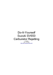
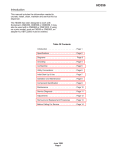
PRIMARY
DRIVEN
GEAR
12-47
CONSTRUCTION
• The primary driven gear washer has been united to the spacer from SV650K1/SK1 ('01-model) as shown
in the illustration .
•
02
3I
•
O5
•
Washer
Spacer
Primary driven gear assembly
Washer
Clutch sleeve hub
Lock washer
Clutch sleeb hub nut
X, Y-MODELS
L
L.
• Spacer
Primary driven gear assembly
03 Washer
• Clutch sleeve hub
~5 Lock washer
• Clutch sleeb hub nut
20
From K1-MODEL