1
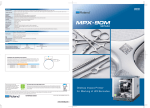
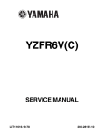
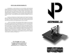
Digital Knight
Digital Mug Press
Version 2-11
1
Contents
Introduction............................................................................................................. 3
Setup & Suggestions.......................................................................................... 4
Normal Operation................................................................................................... 5
Normal Operating Mode.................................................................................... 5
Setting Temperature........................................................................................... 5
Setting Time....................................................................................................... 6
Pre-Press Timer.................................................................................................. 6
Setting Pressure.................................................................................................. 7
Important Pressure Notes................................................................................... 7
Additional Green Pads....................................................................................... 8
Replacement Green Pads................................................................................... 8
Guidelines, Tips & Settings............................................................................... 9
ERR Mode......................................................................................................... 10
Over-Temp Alarm............................................................................................. 10
Programmable Presets............................................................................................ 11
How Presets Work............................................................................................ 11
Loading a Preset................................................................................................ 11
Editing/Programming a Preset.......................................................................... 12
A Walkthrough Tutorial for using Presets........................................................ 13
User Menus............................................................................................................ 14
Entering the user menus & options................................................................... 14
Fahrenheit / Celsius........................................................................................... 14
Timer Counter Units......................................................................................... 14
Recorded Pressings (User Odometer)............................................................... 15
Pressure Minimum............................................................................................ 15
Pressure Maximum........................................................................................... 15
Temperature Drop Sense................................................................................... 15
Keypad Beeper.................................................................................................. 16
Alarms............................................................................................................... 16
Finished Warning Beep..................................................................................... 17
Prepress Timer.................................................................................................. 17
Prepress Alarms................................................................................................ 18
Operator Lockout.............................................................................................. 18
Parts / Maintenance / Misc..................................................................................... 19
Replacement Parts............................................................................................. 19
Maintenance...................................................................................................... 19
Wiring Diagram................................................................................................ 20
Troubleshooting................................................................................................ 21
Troubleshooting (cont.)..................................................................................... 22
Limited Warranty.............................................................................................. 23
2
Introduction
Congratulations on your purchase of the DK3 mug press! This heat
press machine has many exciting features, all of which are meant to
help make your heat transfer pressing endeavors as successful and
easy as possible. Please take the time now to thoroughly read through
this manual to become acquainted with them. It will explain some key
features, concepts and methods that will save much time and effort in
using this press and in your heat pressing applications.
Throughout this manual, many areas and components of this machine
will be referred to by specific names. Please refer to the illustrations
below in order to become familiar with some of the terminology used
in this manual.
Handle
Timer Tilt Sensor
Clamp / Linkage
Quick Release Pin
Pressure Knob
Controller
Heater Band
Power Inlet
On/Off Switch
Base
Default Operating Mode of Controller
Temperature
°F/°C Indicator
Ready/Heating Indicator
Open/Timing/Done Ind.
Time
Pressure Bar Graph
TEMP key
PRG key
Up/Down Arrow keys
3
Setup & Suggestions
•
•
•
•
•
4
Locate the press on a firm, sturdy work surface. Non-skid rubber
matting is especially helpful to keep the press from sliding on the
worksurface.
The height of the bench/work space the press is located on would be
ideally 27” to 32” high. The higher the press, the more difficult to
close/lock.
Attach the power cord from the rear to the backside of the controller.
There is a power inlet on the back panel of the control box for the
power cord.
Make sure the power cord can not be pulled on. Make sure there is no
tension on the inlet socket that the power cord plugs into
The press can be left in the opened or closed position. There is no
difference in heating/performance. At certain pressure settings, the
handle may rest in the closed position. This is not a problem.
Normal Operation
Normal Operating Mode
The normal operating mode of
the press will display the current
actual Temperature at the top of
the screen and the time setting
or elapsed time below the
temperature.
The right side the screen will
indicate the heating status by
stating HEATING, READY, both
of those words, or none at all,
depending on if it is cooling down or heating up to the set temperature.
READY is shown only if the current temperature is within 5 degrees of
the set point temperature.
The right side of the screen will also indicate the timing status by stating
OPEN, TIMING or DONE. The DONE indicator may remain on in
some cases until the press is opened back up.
The pressure bar graph digits at the bottom of the screen are not used
on the DK3.
Setting Temperature
From the normal operating mode,
simply press the TEMP key to set the
temperature.
The flashing 3-digit number is the
temperature setting (not the actual
current temp). Use the Arrow Keys to
set the desired temperature. Hold them
down to increase rapidly, press both
together to set it to 350°F.
Press TEMP again to lock in the setting.
5
Setting Time
From the normal operating mode, simply
use the Arrow Keys ONLY to set the
time. Do not touch the PRG key.
Hold down either the Up or Down arrow
key for more than 2 seconds and the time
will increase rapidly.
Press BOTH Arrow Keys and the time
will reset to 00 seconds.
Pre-Press Timer
There is a second timer available for
use, called the “Pre-Press Timer”.
This feature is useful if a multiple-step
process is performed.
For example: If a product must be
pre-pressed for 5 seconds before a
main pressing cycle of 20 seconds, the
Prepress timer can be set for 5 secs, and
the main timer for 20. When the operator closes the press, the 5-sec
time counts down. When the operator opens the press, the time setting
switches to 20 seconds.
The word PREPRESS will be displayed next to the pre-press time setting
when it is active. To set the pre-press time, simply use the Arrow Keys
to set the time. If PREPRESS is not displayed next to the time, quickly
close and then open the press to switch to the prepress time.
To turn ON the prepress timer feature, enter the User Options Menus
(see page 15) and go to the PPR setting and turn it ON. (see page 17)
6
Setting Pressure
The DK3 is fully adjustable to accommodate various size mugs.
•
•
•
•
To decrease the pressure,
allowing for larger diameter
mugs, or to make the tension
lighter, turn the pressure knob
to the right, clockwise.
The heater band will rise away
from the front of the press. The
allen screw will enter into the
plunger shaft deeper.
To increase the pressure,
allowing for smaller diameter
mugs, or to make the tension tighter, turn the pressure knob to the left,
clockwise.
The heater band will come closer to the front of the press. The allen screw
will come out of plunger shaft further.
Important Pressure Notes
The clamp must lock in place for a successful transfer. Do not simply
close the handle in a resting position. The handle must lock and clamp
down so that there is significant pressure on the mug. If the clamp
assembly can not be locked, then the pressure knob must be adjusted.
Do not over tighten the pressure. If it requires a lot of force to close
the press onto the mug, the black adjustment knob or mug handle can
break. The handle should be closable with one hand of the operator
when properly lubricated.
Sublimation inks do not require much pressure for a good transfer.
However - many styles of imprintable mugs are not straight, especially
at the top & bottom of the mug. For this reason, heavier pressure helps
press the transfer right up against the entire surface of the mug. Set the
pressure adjustment so that there is a firm clamping force. This will
insure good contact, and great results.
When the press is hot, and after much use, the pressure assembly may
be difficult to adjust. An ALLEN KEY has been included to allow for
easy adjustment.
7
Additional Green Pads
For mugs or cylinder shaped items less than approximately 3” in
diameter, an additional 1/16” or 1/8” green heat conductive pad may be
required.
Wrap this additional pad around the smaller diameter mug to make up
for the difference in size. Additional time may be needed for pressing to
make up for heat loss through the extra padding.
Replacement Green Pads
The green pads on the heater will regularly wear and need replacement.
Contact the factory for replacement pads. Make sure you indicate which
pad thickness your version press uses: either 1/16” or 1/8” thick green
heat conductive padding.
Some mugs and users can achieve several hundred mugs or more from
a single pad, where other applications and users need to replace the pad
more often. As a general rule of thumb, the heavier the pressure, and the
wider range of mugs/cylinders pressed in the press, the more often the
pad needs replacing. The straighter and more consistent the mug size
used in the press, the longer the pad life.
It is normally time to change the green pad when light spots begin
appearing where normally good results appeared prior, and obvious
indents, chips, cuts, and sagging of the pad occur.
8
Guidelines, Tips & Settings
Set the DK3 to 400°F for 5 minutes to begin, and try 30 seconds less
on subsequent mugs if good results are achieved. Always use a plain
paper cover sheet OR teflon liner over the entire mug surface on top
of the transfer to protect the mug surface. For some offset transfers,
high energy sublimation inks, hard mug coatings or full bleed handle to
handle transfers, it may be necessary to increase the time to 5.5 minutes
or more.
ALWAYS TRIM the cover sheet down to within the flat surface of the
mug. Allowing papers/cover material to overlap the edges of the mug
will cause wrinkling and white lines in the image. If the results are not
acceptable, or you are using laser transfer papers or other type of transfer
media, contact your transfer ink or paper supplier for recommended
guidelines. Please note that when pressing mugs, it is perfectly normal to have
a significant drop of 30+° in temperature during the first part of the
cycle due to the mug absorbing a large amount of heat.
One recommendation for increasing production and decreasing pressing
time is to use a pre-heating oven, such as a small toaster oven or other
countertop batch heater. Pre-tape and wrap the mugs, set the small oven
to 300°F, and have mugs preheating inside while other mugs are being
pressed. This will invest heat into the mass of the ceramic, without
activating the sublimation, so that the final pressing in the DK3 will
be significantly faster. Times can then be lowered down to 2.5 to 3.5
minutes and in some cases less.
Some mugs may have irregular shapes. The top and especially bottom
rims of the mugs may taper inward. This will result in the paper
possibly wrinkling at the edge of the mug. Normally this will not
affect the transfer elsewhere on the mug. However if attempting to
press full bleed transfers with the image wrapping near the rims of the
mug, this can cause white lines and faded splotches, especially near
the extremities of the mug. This is the result of the mug shape tapering
inward, and the paper continuing to stiffly extend outward causing
wrinkling. The solution to this is to dampen (with wet fingers or spray
bottle - do not submerge) the cover sheet with water and bend the paper
with the palm of your hand around the edges of the mug. Press the mug
as usual and the water will help “paper mache” or cast/mold the paper
around the mug curvature. This will help alleviate white lines and white
splotches on the mug.
9
ERR Mode
During operation of the press, if there
is a loss of signal from the temperature
sensor wire, the ERR display will
appear.
This is a safety feature that will shut off
the relay so the press will not overheat
aimlessly without a temperature signal.
Once the temperature signal is restored (no longer broken, or plugged
back into the control) the press will resume the temperature display, and
start heating if necessary. If ERR persists, contact support.
Over-Temp Alarm
If the press heats beyond the set
temperature by 40 degrees or greater,
the OverTemp alarm will sound.
This is a safety feature that warns the
operator of a possible thermal run-away
of the press. This means the press relay
may be locked in a heating position
where it will never stop heating, to a
possibly harmful temperature level.
If the OverTemp alarm sounds, set the temperature to a higher value
than the current actual temp. Wait 30 seconds and then reset the press to
your desired temperature and Watch Carefully. Do not let the press rise
to extremely high temps.
If it continues to rise, turn off the press and let it cool off to room
temperature. Turn the power back on and immediately set the temperature
to a low setting like 200°F. Wait for the press to heat up. When the press
displays “READY”, monitor the temperature and see if it continues to
heat to a level that the OverTemp alarm activates again. If so, contact
the factory.
10
Programmable Presets
How Presets Work
There are 70 programmable presets in the controller. The operator can
store a Temperature, Time, Prepress Time, and Pressure setting in each
preset.
When a preset program is loaded by the operator, the Current Temperature
Setting, Time and Prepress Settings (if there is a Prepress setting in that
preset) are updated in the normal operating mode.
The pressure is NOT set for the operator mechanically. A brief display
of the pressure value in the preset is shown while updating the current
settings. This is simply a reference... a reminder of what pressure setting
the operator must adjust for that preset.
There are 2 main functions to using the presets. LOADING and EDITING
the preset. LOADING a preset simply means selecting a desired preset,
and returning to the normal operating mode where the current settings
are changed. EDITING a preset is when the operator actually changes
the preset’s settings.
Loading a Preset
To enter the presets, press the PRG
key.
SET will display on the screen.
Use the Arrow Keys to select a preset
from 00 to 70.
Press PRG to return to the normal
operating mode. The current active Temperature, Time & Prepress time
settings (if there is a prepress setting in that preset) are now updated
with the presets values.
11
Editing/Programming a Preset
To edit a preset and change it’s values to your
own desired settings, you simply use the TEMP
key while in the SET preset mode.
From the normal operating mode, press the PRG
key. SET displays on the screen. Use the Arrow
Keys to select the preset # you wish to edit.
Press the TEMP key. The temperature will flash.
Use the Arrow Keys to set the temperature for
that preset.
Press the TEMP key. The time will flash. Use
the Arrow Keys to set the time for that preset.
Press the TEMP key. The Prepress time will
flash. Use the Arrow Keys to set the Prepress
time. Set the Prepress time to 00 if only one timer
is to be used for that preset. Setting Prepress to
00 will disable the Prepress feature.
Press the TEMP key. The Pressure reference
value will flash. Use the Arrow Keys to set the
pressure for that preset. This will display 0 to 9
for presses configured for Bar Graph Pressure
readout, and will display 0:00 to 10:00 for
presses configured for a Height Gauge readout.
Press the TEMP key. The screen returns to the
preset #. Press PRG to return to the normal
operating mode, or use the Arrow Keys to select
a different preset and edit that as well.
12
A Walkthrough Tutorial for using Presets
Here is a tutorial of programming 2 different presets, and then an
example of using them in normal daily operations. Do this walkthrough
to practice using presets.
Part 1: Programming 2 different presets.
From the normal operating mode, press PRG. SET appears.
Use the arrow keys to select SET 01.
Press TEMP. Set the flashing temperature to 400 with the arrow keys.
Press TEMP. Set the flashing time to 45 with the arrow keys.
Press TEMP. Set the flashing Prepress time to 00 with the arrow keys.
Press TEMP. Set the flashing Pressure ref to 6 with the arrow keys.
Press TEMP. Use the arrow keys to select SET 02.
Press TEMP. Set the flashing temperature to 350 with the arrow keys.
Press TEMP. Set the flashing time to 12 with the arrow keys.
Press TEMP. Set the flashing Prepress time to 3 with the arrow keys.
Press TEMP. Set the flashing Pressure ref to 8 with the arrow keys.
Press TEMP. Press PRG to leave the preset mode.
Presets SET 01 and SET 02 have now been programmed.
Part 2: Loading the presets. Let’s say we are powering on the machine
and starting a job. The first job will need to use preset 01, and later on
the next job will need preset 02.
From the normal operating mode, press PRG. SET appears.
Use the arrow keys to select SET 01 then Press PRG. Done!
The press is now set for 400°F and 45 seconds and will start to heat to
that temperature. When leaving the presets, the screen briefly displayed
PRS 6 - indicating you must manually set the clamping pressure so the
bar graph shows 6 (or close to it) at the bottom of the screen.
Now let’s change to the next job. Press PRG. SET appears.
Use the arrow keys to select SET 02 then Press PRG. Done!
The press is now set for 350°F, 12 secs, 3 prepress, and you are reminded
to set the pressure heavier to 8 on the bar graph display (when closed).
That’s it! You can load a preset as often as needed: just press PRG, pick
the preset you want with the Arrow Keys, and press PRG again.
13
User Menus
Entering the user menus & options
There are many useful features beyond simply setting time & temperature,
and storing presets. All of these additional features are available to the
operator in the User Menus.
To access the user menus, simply press TEMP & PRG at the same
time from the normal operating mode and let go.
(Try to use two hands and press the keys at the exact same time. If one
key is pressed too early from the other, the temperature setting or preset
modes may be activated instead. Turn the press off and then on and try
again.)
Fahrenheit / Celsius
The current and set temperature can be
displayed in °F or °C. After entering the
user menus (see above), use the arrow
keys to select F or C. Press PRG to move
to the next menu item.
Timer Counter Units
The timer and Prepress timer can be set
for mins/secs (default) or hours/mins. If
special applications need a higher timer
range than 99 mins, 59 secs, this can be
changed. After entering the user menus
(see top of page), Press PRG until CNT
displays. Use the arrow keys to select
SEC or HR. Press PRG to move to the
next menu item.
14
Recorded Pressings (User Odometer)
There is an “odometer” that records
pressing cycles done. This can be cleared
and reset to 0 at any time when needed.
The figure scrolls and it’s beginning and
end are separated by a “-” sign.
After entering the user menus (see
top of page 14), Press PRG until REC
displays. Use the arrow keys to reset the
counter to 0. Press PRG to move to the
next menu item.
Pressure Minimum
This menu item is not applicable to the DK3 heat
press. Press PRG to move to the next menu item.
Pressure Maximum
This menu item is not applicable to the DK3 heat
press. Press PRG to move to the next menu item.
Temperature Drop Sense
The press can be set to alarm if the
temperature drops a certain range below
the set temperature. This is useful to
warn the operator if the press is too
far out of temperature range during
excessive use.
After entering the user menus (see
top of page 14), Press PRG until DRP
displays. Use the arrow keys to set it to OFF (default), or 10, 20, 30, etc.
If the current temperature drops below the set temperature by that many
degrees, and alarm will sound. Press TEMP to silence the alarm.
Press PRG to move to the next menu item.
15
Keypad Beeper
The keypad beep can be silenced if
needed. After entering the user menus
(see top of page 14), Press PRG until
BEP displays. Use the arrow keys to set
it to ON or OFF.
Press PRG to move to the next menu
item.
Alarms
The timer alarm can be adjusted for
different beeping patterns. This can
differentiate between multiple presses,
and allow the operator to have a short
beep or a continuously repeating beep.
After entering the user menus (see
top of page 14), Press PRG until ALR
displays. Use the arrow keys to set it to
OFF, or 1 through 10.
Press PRG to move to the next menu item.
16
• denotes a short beep.
_ denotes a longer beep.
~ denotes infinite loop.
Alarm #
Off
01
02
03
04
05
06
07
08
09
10
Alarm Pattern
No alarm
•••_
•••_ ~
•• _
•• _ ~
•••
••• ~
_ ~
_
•
• (shorter)
Finished Warning Beep
The press can sound a beep on the last
3 seconds of the timer or Prepress timer
countdown. This is useful if the press
is automatic and the operator needs a
warning that the press is about to finish, open, or pop-up dramatically.
After entering the user menus (see top
of page 14), Press PRG until FWB
displays. Use the arrow keys to set it to
ON or OFF.
Press PRG to move to the next menu item.
Prepress Timer
The press can cycle back and forth
between two distinct timer settings:
the normal countdown timer, and a 2nd
Prepress timer. (see page 6). This menu
item turns the Prepress timer ON or
OFF.
After entering the user menus (see top of
page 14), Press PRG until PPR displays.
Use the arrow keys to set it to ON or
OFF.
If PPR is set to OFF, pressing PRG will return to the normal operating
mode.
If PPR is set to ON, pressing PRG will move to the next menu item.
17
Prepress Alarms
The Prepress timer alarm can be
adjusted for different beeping patterns.
This allows for differentiating from the
normal timer, and can allow the operator
to have a short beep or a continuously
repeating beep.
After entering the user menus (see top of
page 14), Press PRG until AL2 displays. The PPR menu must be set to ON for this menu to be visible. Use the
arrow keys to set AL2 to OFF, or 1 through 10.
Press PRG to move to the next menu item.
• denotes a short beep.
_ denotes a longer beep.
~ denotes infinite loop.
Alarm #
Off
01
02
03
04
05
06
07
08
09
10
Alarm Pattern
No alarm
•••_
•••_ ~
•• _
•• _ ~
•••
••• ~
_ ~
_
•
• (shorter)
Operator Lockout
An operator lockout feature is available
to the owner of the press. This prevents
the average user from changing any
settings or adjusting anything on the
controller.
Contact the factory for instructions on
using this feature.
18
Parts / Maintenance / Misc
Replacement Parts
Here is a list of current replaceable parts on the DK3 as of the writing
of this manual:
HCR-16510.......................HEAT CONDUCTIVE 1/16 X 5 X 10½
HCR-18510.......................HEAT CONDUCTIVE 1/8 X 5 X 10½
DK3-BANDHTR..............DK3 BAND HEATER ASSEMBLY 110V
DK3-BANDHTR2............DK3 BAND HEATER ASSEMBLY 220V
MEN-DCCLP ..................DC CLAMP ASBLY W/HANDLE & PIN
RPK-DK3EXT..................DK3 EXTENSION SCREW UPGRADE KIT
FAS-AE½133SS...............½-13 X 3 SOCKET FLAT HEAD STAINLESS
MEN-E0826......................1.75” DIA LOW-PROFILE BLACK KNOB
MEN-DKSHFT.................DK/DC CLAMP PLUNGER SHAFT
TOL-516ALNKEY...........5/16” ALLEN KEY
DKA-CTRLC....................DIGITAL KNIGHT PROCESSOR BOARD
DKA-CTRLP....................DIGITAL KNIGHT POWER BOARD
ELN-KM0227A1..............DIGITAL KNIGHT MEMBRANE KEYPAD
RPK-DKPWR...................DK POWER INLET/SWITCH/CORD KIT
DKA-HARNESS2............DK 6-PIN PLUG TIMER WIRE & MERC
ELN-K263TC...................K-3” FLAT X 26” THERMOCOUPLE 1” STRIP
SHN-DK3TOP..................DK3 FRAME TOP PANEL
SHN-DK3BACK..............DK3 FRAME BACK PANEL
SHN-DK3FRONT............DK3 FRAME FRONT PANEL
DK3-FRAME....................DK3 MACHINE FRAME
Maintenance
The majority of the press has been designed to be as maintenance free
as possible. There are only a few aspects of the machine that should be
monitored to insure proper operation.
•
The green pad on the heater is a regular replacement item. Depending
on the number of mugs and size/variety of items pressed in the DK3, the
green pad may have to be replaced more often than if only one style mug
is pressed.
•
The heater band may have small clips wrapping around the edges of the
cylinder. It is normal for these clips to wear, bend & break off especially
at the edges that come close the mug handle. This is normal and will not
affect print quality or heater life. These tabs are for original heater assembly
purposes only.
19
Wiring Diagram
20
Troubleshooting
The following information attempts to address the most probable
mechanical and user issues with the press. Most issues with heat transfer
presses are application related. That is, they have to do with the results
of a particular transfer application.
For technical support on problems having to do with the final results
of a particular transfer paper or media, please contact the supplier of
that transfer media. Generally, the machinery manufacturer is unable
to support the myriad of different transfer papers, inks and imprintable
items on the market from other resellers.
Q.
The timer does not start when I close the heat platen, or the timer
does not reset when I open the press up.
A.
There are several probable causes for this. The timer is activated
by a micro-tilt-sensor stuck to the black handle. First: When the head of
the machine is opened, the tilt sensor needs to be tilted slightly upward
to signal the controller to stop/reset. When the head of the machine is
closed, the timer sensor needs to be tilted downward (towards the floor)
to signal the controller to start counting. Verify this. Second: Check the
wire connection from the tilt sensor into the control panel. The timer &
pressure signals go to a small black 6-pin connector on the top of the
circuit board in the control box. Check to make sure this is firmly seated
and plugged into All 6 Gold Pins on the board.
Q.
The control displays Err when it first comes on, and I can not set
the temperature or use the press.
A.
The Err message will display if the heating signal from the platen
has been cut off, interrupted, or the heating sensor has failed. First check
the Lime Green temperature connector that plugs into the digital control.
At the top of the controller, there is a green connector that plugs in with
2 small wires. This is the temperature sensor wire. Check to make sure
is it properly seated. If after unplugging and plugging the lime green
connector the Err message still appears; unplug the green connector and
remove the 2 tiny wires from the lime green plug. Cut them back 1/4”
and strip them so they have new connections. Reconnect them to the
lime green plug so they are screwed in tightly and can not pull out. Plug
the green plug back in and turn the press on. If this does not solve the
issue, contact the factory for assistance.
21
Troubleshooting (cont.)
Q.
I press the keys on the keypad, and there is no sound or response
from the controller.
A.
Check the connection of the keypad to the controller. This is
inside the top panel. The keypad connector passes in through the top
panel. It should wind around the first circuit board and be seated fully
into the connector. The keypad ELN-KM0227A1 may need to be
replaced and can be purcahsed at www.heatpress.com/support.php
Q.
The press takes longer than 5 minutes to heat up.
A.
The heater band should usually have a 2.5 to 4 minute heat-up
time. If the press takes significantly longer than this amount of time, this
is a sign of heater failure. This slower heat-up time will require much
longer printing times to allow the element to recover when a mug is
placed ion the press. Replace the heater band.
Q.
There are white spots or faded areas on the finished mug.
A.
Refer to the guidelines and tips for printing on page 9. Replace
the green pad if worn or indents/wear marks correspond to problem
print-areas on the mug.
Q.
There are white lines or streaks on the finished mug.
A.
The mugs are not straight, hold a straight edge to the sides of
the mug and hold it up to the light to verify. Most likely there is an
inward curvature especially at the bottom of the mug. Use the ‘wetting’
technique described on page 9 and on separate guidelines/tips sheet for
pressing mugs. ALSO - the heater band may be conical (not cylindrical).
Loosen the 4 large silver bolts holding the clamp/handle assembly in
place. The handle should be able to move around. Clamp a mug tightly
in the heater (to level the heater against the mug - back to a cylindrical
shape) - and tighten the 4 bolts back up. This will level and even out the
heater to the mug so they are both cylindrical in shape to each other.
Q.
I can not adjust pressure tight enough, or the press is too tight on
the mug no matter how much I loosen it.
A.
There are spacer washers under the top 2 bolts and black clamp,
on top of the white cover. These tilt the clamp forward/backward and
significantly change the curvature of the heater band. It may be necessary
to add/subtract (1) washer Only from the top to positions to adjust the
curvature. Contact the factory for further written instructions.
22
Limited Warranty
Geo Knight & Co warrants that the press is free from defects in both material
and workmanship (1) Year from the date of invoice to the buyer. If any parts or
workmanship are found to be defective in manufacture, Geo Knight & Co will repair
or replace the defective parts or workmanship. The green rubber liner is a consumable
item and not covered under the standard 1 year warranty. Geo Knight & Co also
warrants that the Digital Knight heat control is free from defects in both material &
workmanship and is covered under no-charge support for (3) years. Geo Knight & Co
also warrants that the heating functionality of the heater band is warranted for (3) years
or 3,000 pressing cycles - whichever comes first - for 110V USA units, (1)-year or 1000
pressing cycles - whichever comes first - for 220 volt & international units, provided it
is owned by the original purchaser. This warranty on the heating element does not cover
temperature sensor failure, outside heater wire damage, or disconnection. After 1 year,
the number of pressing cycles of the machine must be confirmed by returning the press
to a technician at the factory in order to honor the heater band warranty, otherwise the
replacement heater band is chargeable. This entire limited warranty covers all parts
to repair the defects, except when damage results from accident, alteration, misuse or
abuse, or when the machine has been improperly installed, or modified in any way.
If a press covered by the (1) year limited warranty must be returned to the
factory for repairs, Geo Knight & Co shall make every effort to repair buyer’s press.
However, Geo Knight & Co reserves the exclusive right to determine whether to repair
or replace a dysfunctional press. If Geo Knight & Co authorizes a replacement press, the
warranty of the replacement press shall expire on the anniversary date of the original
machine’s invoice to the buyer.
There are no warranties which extend beyond the description on the face
hereof. Seller disclaims any implied warranty of merchantability and/or any implied
warranty of fitness for a particular purpose, and buyer agrees that the goods are sold
“as is”. Geo Knight & Co does not warrant that the functions of the press will meet the
buyers requirements or expectations. The entire risk as to use, quality and performance
of the press lies with the buyer. In no event will Geo Knight & Co be liable for any
damages, including loss of profits, destruction of goods or any other special, incidental,
consequential or indirect damages arising from the use of the press or accompanying
materials. This limitation will apply even if Geo Knight & Co or its authorized agent
has been advised of the possibility of such damage.
Geo Knight & Co Inc
52 Perkins St, Brockton MA 02302 USA
(508)588-0186 - Fax (508) 587-5108
[email protected] - www.heatpress.com
23