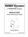
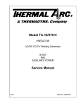
1
ECONO-PAK 50
Air Plasma Cutting Power Supply
Service Manual
September 5, 1999
Manual No. 0-2671
WARNING
Read and understand this entire Service Manual and your
employer’s safety practices before installing, operating, or
servicing the equipment.
WARNING
While the information contained in this Service Manual represents our best judgement, Thermal Dynamics Corporation
assumes no liability for its use.
Econo-Pak 50 Air Plasma Cutting Power Supply
Service Manual Number 0-2671
Published by:
Thermal Dynamics Corporation
Industrial Park No. 2
West Lebanon, New Hampshire, USA 03784
(603) 298-5711
Copyright 1997 by
Thermal Dynamics Corporation
All rights reserved.
Reproduction of this work, in whole or in part, without written
permission of the publisher is prohibited.
The publisher does not assume and hereby disclaims any liability
to any party for any loss or damage caused by any error or
omission in the Econo-Pak 50 Air Plasma Cutting Power Supply
Service Manual, whether such error results from negligence,
accident, or any other cause.
Printed in the United States of America
September 1999
TABLE OF CONTENTS
SECTION 1:
GENERAL INFORMATION .................................................................................................. 1
1.01
1.02
1.03
1.04
1.05
1.06
1.07
1.08
Notes, Cautions and Warnings ...................................................................... 1
Important Safety Precautions ........................................................................ 1
Publications ................................................................................................... 2
Note, Attention et Avertissement ................................................................... 3
Precautions De Securite Importantes ............................................................ 3
Documents De Reference ............................................................................. 5
Declaration of Conformity .............................................................................. 7
Statement of Warranty ................................................................................... 8
SECTION 2:
INTRODUCTION ................................................................................................................. 9
2.01 Scope Of Manual ........................................................................................... 9
2.02 General Service Philosophy .......................................................................... 9
2.03 Service Responsibilities ................................................................................. 9
SECTION 3:
DESCRIPTION .................................................................................................................. 11
3.01 Scope of Manual .......................................................................................... 11
3.02 General Description ..................................................................................... 11
3.03 Specifications/Design Features ................................................................... 11
SECTION 4:
CUSTOMER/OPERATOR SERVICE .................................................................................. 13
4.01
4.02
4.03
4.04
4.05
4.06
4.07
4.08
Introduction .................................................................................................. 13
General Maintenance .................................................................................. 13
Common Operating Faults ........................................................................... 14
Troubleshooting Guides ............................................................................... 14
Basic Troubleshooting Guide ....................................................................... 14
Advanced Troubleshooting Guide ................................................................ 15
Troubleshooting Flow Charts ....................................................................... 16
Test Procedures ........................................................................................... 24
SECTION 5:
REPAIRS & REPLACEMENT PROCEDURES ................................................................... 27
5.01
5.02
5.03
5.04
Introduction .................................................................................................. 27
Anti-Static Handling Procedures .................................................................. 27
Parts Replacement - General Information .................................................... 27
Power Supply Component Replacement Procedures .................................. 28
SECTION 6:
PARTS LISTS ..................................................................................................................... 31
6.01
6.02
6.03
6.04
Introduction .................................................................................................. 31
Ordering Information .................................................................................... 31
Front and Rear Panel Replacement Parts List ............................................. 32
Internal Component Replacement Parts List ............................................... 34
APPENDIX I: SYSTEM SCHEMATIC ......................................................................................... 36
TABLE OF CONTENTS (continued)
SECTION 1:
GENERAL INFORMATION
GASES AND FUMES
Gases and fumes produced during the plasma cutting
process can be dangerous and hazardous to your health.
1.01 Notes, Cautions and Warnings
• Keep all fumes and gases from the breathing area.
Keep your head out of the welding fume plume.
Throughout this manual, notes, cautions, and warnings
are used to highlight important information. These highlights are categorized as follows:
• Use an air-supplied respirator if ventilation is not
adequate to remove all fumes and gases.
NOTE
• The kinds of fumes and gases from the plasma arc
depend on the kind of metal being used, coatings
on the metal, and the different processes. You must
be very careful when cutting or welding any metals which may contain one or more of the following:
An operation, procedure, or background information which requires additional emphasis or is helpful in efficient operation of the system.
CAUTION
Antimony
Arsenic
Barium
Beryllium
Cadmium
A procedure which, if not properly followed, may
cause damage to the equipment.
Chromium
Cobalt
Copper
Lead
Manganese
Mercury
Nickel
Selenium
Silver
Vanadium
• Always read the Material Safety Data Sheets (MSDS)
that should be supplied with the material you are
using. These MSDSs will give you the information
regarding the kind and amount of fumes and gases
that may be dangerous to your health.
WARNING
A procedure which, if not properly followed, may
cause injury to the operator or others in the operating area.
• For information on how to test for fumes and gases
in your workplace, refer to item 1 in Subsection
1.03, Publications in this manual.
1.02 Important Safety Precautions
• Use special equipment, such as water or down draft
cutting tables, to capture fumes and gases.
WARNINGS
• Do not use the plasma torch in an area where combustible or explosive gases or materials are located.
• Phosgene, a toxic gas, is generated from the vapors
of chlorinated solvents and cleansers. Remove all
sources of these vapors.
OPERATION AND MAINTENANCE OF
PLASMA ARC EQUIPMENT CAN BE DANGEROUS AND HAZARDOUS TO YOUR
HEALTH.
ELECTRIC SHOCK
Plasma arc cutting produces intense electric and
magnetic emissions that may interfere with the
proper function of cardiac pacemakers, hearing
aids, or other electronic health equipment. Persons who work near plasma arc cutting applications should consult their medical health professional and the manufacturer of the health
equipment to determine whether a hazard exists.
Electric Shock can injure or kill. The plasma arc process
uses and produces high voltage electrical energy. This
electric energy can cause severe or fatal shock to the operator or others in the workplace.
To prevent possible injury, read, understand and
follow all warnings, safety precautions and instructions before using the equipment. Call 1-603298-5711 or your local distributor if you have any
questions.
• Wear dry gloves and clothing. Insulate yourself from
the work piece or other parts of the welding circuit.
• Never touch any parts that are electrically “live” or
“hot.”
• Repair or replace all worn or damaged parts.
• Extra care must be taken when the workplace is
moist or damp.
Date: 6/22/99
1
GENERAL INFORMATION
• Install and maintain equipment according to NEC
code, refer to item 9 in Subsection 1.03, Publications.
• To protect your eyes, always wear a welding helmet or shield. Also always wear safety glasses with
side shields, goggles or other protective eye wear.
• Disconnect power source before performing any service or repairs.
• Wear welding gloves and suitable clothing to protect your skin from the arc rays and sparks.
• Read and follow all the instructions in the Operating Manual.
• Keep helmet and safety glasses in good condition.
Replace lenses when cracked, chipped or dirty.
• Protect others in the work area from the arc rays.
Use protective booths, screens or shields.
FIRE AND EXPLOSION
• Use the shade of lens as suggested in the following
per ANSI/ASC Z49.1:
Fire and explosion can be caused by hot slag, sparks, or
the plasma arc.
• Be sure there is no combustible or flammable material in the workplace. Any material that cannot be
removed must be protected.
• Ventilate all flammable or explosive vapors from
the workplace.
Arc Current
Minimum Protective
Shade No.
Suggested
Shade No.
Less Than 300*
8
9
300 - 400*
9
12
400 - 800*
10
14
* These values apply where the actual arc is clearly
seen. Experience has shown that lighter filters
may be used when the arc is hidden by the workpiece.
• Do not cut or weld on containers that may have held
combustibles.
• Provide a fire watch when working in an area where
fire hazards may exist.
1.03 Publications
• Hydrogen gas may be formed and trapped under
aluminum workpieces when they are cut underwater or while using a water table. DO NOT cut
aluminum alloys underwater or on a water table
unless the hydrogen gas can be eliminated or dissipated. Trapped hydrogen gas that is ignited will
cause an explosion.
Refer to the following standards or their latest revisions
for more information:
1. OSHA, SAFETY AND HEALTH STANDARDS,
29CFR 1910, obtainable from the Superintendent of
Documents, U.S. Government Printing Office, Washington, D.C. 20402
2. ANSI Standard Z49.1, SAFETY IN WELDING AND
CUTTING, obtainable from the American Welding
Society, 550 N.W. LeJeune Rd, Miami, FL 33126
NOISE
Noise can cause permanent hearing loss. Plasma arc processes can cause noise levels to exceed safe limits. You
must protect your ears from loud noise to prevent permanent loss of hearing.
3. NIOSH, SAFETY AND HEALTH IN ARC WELDING AND GAS WELDING AND CUTTING, obtainable from the Superintendent of Documents, U.S.
Government Printing Office, Washington, D.C. 20402
• To protect your hearing from loud noise, wear protective ear plugs and/or ear muffs. Protect others
in the workplace.
4. ANSI Standard Z87.1, SAFE PRACTICES FOR OCCUPATION AND EDUCATIONAL EYE AND FACE
PROTECTION, obtainable from American National
Standards Institute, 1430 Broadway, New York, NY
10018
• Noise levels should be measured to be sure the decibels (sound) do not exceed safe levels.
5. ANSI Standard Z41.1, STANDARD FOR MEN’S
SAFETY-TOE FOOTWEAR, obtainable from the
American National Standards Institute, 1430 Broadway, New York, NY 10018
• For information on how to test for noise, see item 1
in Subsection 1.03, Publications, in this manual.
6. ANSI Standard Z49.2, FIRE PREVENTION IN THE
USE OF CUTTING AND WELDING PROCESSES,
obtainable from American National Standards Institute, 1430 Broadway, New York, NY 10018
PLASMA ARC RAYS
Plasma Arc Rays can injure your eyes and burn your skin.
The plasma arc process produces very bright ultra violet
and infra red light. These arc rays will damage your
eyes and burn your skin if you are not properly protected.
GENERAL INFORMATION
7. AWS Standard A6.0, WELDING AND CUTTING
CONTAINERS WHICH HAVE HELD COMBUSTIBLES, obtainable from American Welding Society,
550 N.W. LeJeune Rd, Miami, FL 33126
2
Date 6/22/99
8. NFPA Standard 51, OXYGEN-FUEL GAS SYSTEMS
FOR WELDING, CUTTING AND ALLIED PROCESSES, obtainable from the National Fire Protection
Association, Batterymarch Park, Quincy, MA 02269
AVERTISSEMENT
9. NFPA Standard 70, NATIONAL ELECTRICAL CODE,
obtainable from the National Fire Protection Association, Batterymarch Park, Quincy, MA 02269
Toute procédure pouvant provoquer des blessures
de l’opérateur ou des autres personnes se trouvant
dans la zone de travail en cas de non-respect de la
procédure en question.
10. NFPA Standard 51B, CUTTING AND WELDING
PROCESSES, obtainable from the National Fire Protection Association, Batterymarch Park, Quincy, MA
02269
1.05 Precautions De Securite
Importantes
11. CGA Pamphlet P-1, SAFE HANDLING OF COMPRESSED GASES IN CYLINDERS, obtainable from
the Compressed Gas Association, 1235 Jefferson
Davis Highway, Suite 501, Arlington, VA 22202
AVERTISSEMENTS
12. CSA Standard W117.2, CODE FOR SAFETY IN
WELDING AND CUTTING, obtainable from the Canadian Standards Association, Standards Sales, 178
Rexdale Boulevard, Rexdale, Ontario, Canada M9W
1R3
L’OPÉRATION ET LA MAINTENANCE DU
MATÉRIEL DE SOUDAGE À L’ARC AU JET
DE PLASMA PEUVENT PRÉSENTER DES
RISQUES ET DES DANGERS DE SANTÉ.
13. NWSA booklet, WELDING SAFETY BIBLIOGRAPHY obtainable from the National Welding Supply
Association, 1900 Arch Street, Philadelphia, PA 19103
Coupant à l’arc au jet de plasma produit de l’énergie
électrique haute tension et des émissions
magnétique qui peuvent interférer la fonction
propre d’un “pacemaker” cardiaque, les appareils
auditif, ou autre matériel de santé electronique.
Ceux qui travail près d’une application à l’arc au
jet de plasma devrait consulter leur membre
professionel de médication et le manufacturier de
matériel de santé pour déterminer s’il existe des
risques de santé.
14. American Welding Society Standard AWSF4.1, RECOMMENDED SAFE PRACTICES FOR THE PREPARATION FOR WELDING AND CUTTING OF CONTAINERS AND PIPING THAT HAVE HELD
HAZARDOUS SUBSTANCES, obtainable from the
American Welding Society, 550 N.W. LeJeune Rd,
Miami, FL 33126
15. ANSI Standard Z88.2, PRACTICE FOR RESPIRATORY PROTECTION, obtainable from American
National Standards Institute, 1430 Broadway, New
York, NY 10018
Il faut communiquer aux opérateurs et au personnel TOUS les dangers possibles. Afin d’éviter les
blessures possibles, lisez, comprenez et suivez tous
les avertissements, toutes les précautions de sécurité
et toutes les consignes avant d’utiliser le matériel.
Composez le + 603-298-5711 ou votre distributeur
local si vous avez des questions.
1.04 Note, Attention et
Avertissement
Dans ce manuel, les mots “note,” “attention,” et
“avertissement” sont utilisés pour mettre en relief des
informations à caractère important. Ces mises en relief
sont classifiées comme suit :
FUMÉE et GAZ
NOTE
La fumée et les gaz produits par le procédé de jet de
plasma peuvent présenter des risques et des dangers de
santé.
Toute opération, procédure ou renseignement
général sur lequel il importe d’insister davantage
ou qui contribue à l’efficacité de fonctionnement
du système.
• Eloignez toute fumée et gaz de votre zone de respiration. Gardez votre tête hors de la plume de fumée
provenant du chalumeau.
ATTENTION
• Utilisez un appareil respiratoire à alimentation en
air si l’aération fournie ne permet pas d’éliminer la
fumée et les gaz.
Toute procédure pouvant résulter
l’endommagement du matériel en cas de nonrespect de la procédure en question.
Date: 6/22/99
3
GENERAL INFORMATION
• Les sortes de gaz et de fumée provenant de l’arc de
plasma dépendent du genre de métal utilisé, des
revêtements se trouvant sur le métal et des différents
procédés. Vous devez prendre soin lorsque vous
coupez ou soudez tout métal pouvant contenir un
ou plusieurs des éléments suivants:
antimoine
cadmium
mercure
argent
chrome
nickel
arsenic
cobalt
plomb
baryum
cuivre
sélénium
béryllium
manganèse
vanadium
INCENDIE ET EXPLOSION
Les incendies et les explosions peuvent résulter des scories
chaudes, des étincelles ou de l’arc de plasma. Le procédé
à l’arc de plasma produit du métal, des étincelles, des
scories chaudes pouvant mettre le feu aux matières combustibles ou provoquer l’explosion de fumées
inflammables.
• Soyez certain qu’aucune matière combustible ou inflammable ne se trouve sur le lieu de travail.
Protégez toute telle matière qu’il est impossible de
retirer de la zone de travail.
• Lisez toujours les fiches de données sur la sécurité
des matières (sigle américain “MSDS”); celles-ci
devraient être fournies avec le matériel que vous
utilisez. Les MSDS contiennent des renseignements
quant à la quantité et la nature de la fumée et des
gaz pouvant poser des dangers de santé.
• Procurez une bonne aération de toutes les fumées
inflammables ou explosives.
• Ne coupez pas et ne soudez pas les conteneurs ayant
pu renfermer des matières combustibles.
• Pour des informations sur la manière de tester la
fumée et les gaz de votre lieu de travail, consultez
l’article 1 et les documents cités à la page 5.
• Prévoyez une veille d’incendie lors de tout travail
dans une zone présentant des dangers d’incendie.
• Utilisez un équipement spécial tel que des tables de
coupe à débit d’eau ou à courant descendant pour
capter la fumée et les gaz.
• Le gas hydrogène peut se former ou s’accumuler
sous les pièces de travail en aluminium lorsqu’elles
sont coupées sous l’eau ou sur une table d’eau. NE
PAS couper les alliages en aluminium sous l’eau ou
sur une table d’eau à moins que le gas hydrogène
peut s’échapper ou se dissiper. Le gas hydrogène
accumulé explosera si enflammé.
• N’utilisez pas le chalumeau au jet de plasma dans
une zone où se trouvent des matières ou des gaz
combustibles ou explosifs.
• Le phosgène, un gaz toxique, est généré par la fumée
provenant des solvants et des produits de nettoyage
chlorés. Eliminez toute source de telle fumée.
RAYONS D’ARC DE PLASMA
CHOC ELECTRIQUE
Les rayons provenant de l’arc de plasma peuvent blesser
vos yeux et brûler votre peau. Le procédé à l’arc de plasma
produit une lumière infra-rouge et des rayons ultra-violets très forts. Ces rayons d’arc nuiront à vos yeux et
brûleront votre peau si vous ne vous protégez pas
correctement.
Les chocs électriques peuvent blesser ou même tuer. Le
procédé au jet de plasma requiert et produit de l’énergie
électrique haute tension. Cette énergie électrique peut
produire des chocs graves, voire mortels, pour l’opérateur
et les autres personnes sur le lieu de travail.
• Pour protéger vos yeux, portez toujours un casque
ou un écran de soudeur. Portez toujours des lunettes
de sécurité munies de parois latérales ou des lunettes de protection ou une autre sorte de protection oculaire.
• Ne touchez jamais une pièce “sous tension” ou
“vive”; portez des gants et des vêtements secs.
Isolez-vous de la pièce de travail ou des autres parties du circuit de soudage.
• Portez des gants de soudeur et un vêtement
protecteur approprié pour protéger votre peau
contre les étincelles et les rayons de l’arc.
• Réparez ou remplacez toute pièce usée ou
endommagée.
• Prenez des soins particuliers lorsque la zone de travail est humide ou moite.
• Maintenez votre casque et vos lunettes de protection en bon état. Remplacez toute lentille sale ou
comportant fissure ou rognure.
• Montez et maintenez le matériel conformément au
Code électrique national des Etats-Unis. (Voir la
page 5, article 9.)
• Protégez les autres personnes se trouvant sur la zone
de travail contre les rayons de l’arc en fournissant
des cabines ou des écrans de protection.
• Débranchez l’alimentation électrique avant tout travail d’entretien ou de réparation.
• Lisez et respectez toutes les consignes du Manuel
de consignes.
GENERAL INFORMATION
4
Date 6/22/99
• Utilisez la nuance de lentille qui est suggèrée dans
le recommendation qui suivent ANSI/ASC Z49.1:
Courant Arc
Nuance Minimum
Protective Numéro
Nuance Suggerée
Numéro
Moins de 300*
8
9
300 - 400*
9
12
400 - 800*
10
14
4. Norme ANSI Z87.1, PRATIQUES SURES POUR LA
PROTECTION DES YEUX ET DU VISAGE AU
TRAVAIL ET DANS LES ECOLES, disponible de
l’Institut Américain des Normes Nationales (American National Standards Institute), 1430 Broadway,
New York, NY 10018
* Ces valeurs s’appliquent ou l’arc actuel est observé
clairement. L’experience a démontrer que les filtres
moins foncés peuvent être utilisés quand l’arc est
caché par moiceau de travail.
BRUIT
5.
Norme ANSI Z41.1, NORMES POUR LES
CHAUSSURES PROTECTRICES, disponible auprès
de l’American National Standards Institute, 1430
Broadway, New York, NY 10018
6.
Norme ANSI Z49.2, PRÉVENTION DES
INCENDIES LORS DE L’EMPLOI DE PROCÉDÉS
DE COUPE ET DE SOUDAGE, disponible auprès
de l’American National Standards Institute, 1430
Broadway, New York, NY 10018
7. Norme A6.0 de l’Association Américaine du
Soudage (AWS), LE SOUDAGE ET LA COUPE DE
CONTENEURS AYANT RENFERMÉ DES
PRODUITS COMBUSTIBLES, disponible auprès de
la American Welding Society, 550 N.W. LeJeune Rd.,
Miami, FL 33126
Le bruit peut provoquer une perte permanente de l’ouïe.
Les procédés de soudage à l’arc de plasma peuvent
provoquer des niveaux sonores supérieurs aux limites
normalement acceptables. Vous dú4ez vous protéger les
oreilles contre les bruits forts afin d’éviter une perte
permanente de l’ouïe.
8. Norme 51 de l’Association Américaine pour la Protection contre les Incendies (NFPA), LES SYSTEMES
À GAZ AVEC ALIMENTATION EN OXYGENE
POUR LE SOUDAGE, LA COUPE ET LES
PROCÉDÉS ASSOCIÉS, disponible auprès de la
National Fire Protection Association, Batterymarch
Park, Quincy, MA 02269
• Pour protéger votre ouïe contre les bruits forts, portez
des tampons protecteurs et/ou des protections
auriculaires. Protégez également les autres
personnes se trouvant sur le lieu de travail.
• Il faut mesurer les niveaux sonores afin d’assurer
que les décibels (le bruit) ne dépassent pas les
niveaux sûrs.
9. Norme 70 de la NFPA, CODE ELECTRIQUE NATIONAL, disponible auprès de la National Fire Protection Association, Batterymarch Park, Quincy, MA
02269
• Pour des renseignements sur la manière de tester le
bruit, consultez l’article 1, page 5.
1.06 Documents De Reference
10. Norme 51B de la NFPA, LES PROCÉDÉS DE
COUPE ET DE SOUDAGE, disponible auprès de
la National Fire Protection Association,
Batterymarch Park, Quincy, MA 02269
Consultez les normes suivantes ou les révisions les plus
récentes ayant été faites à celles-ci pour de plus amples
renseignements :
1. OSHA, NORMES DE SÉCURITÉ DU TRAVAIL ET
DE PROTECTION DE LA SANTÉ, 29CFR 1910,
disponible auprès du Superintendent of Documents, U.S. Government Printing Office, Washington, D.C. 20402
11. Brochure GCA P-1, LA MANIPULATION SANS
RISQUE DES GAZ COMPRIMÉS EN CYLINDRES,
disponible auprès de l’Association des Gaz
Comprimés (Compressed Gas Association), 1235
Jefferson Davis Highway, Suite 501, Arlington, VA
22202
2. Norme ANSI Z49.1, LA SÉCURITÉ DES
OPÉRATIONS DE COUPE ET DE SOUDAGE,
disponible auprès de la Société Américaine de
Soudage (American Welding Society), 550 N.W.
LeJeune Rd., Miami, FL 33126
12. Norme CSA W117.2, CODE DE SÉCURITÉ POUR
LE SOUDAGE ET LA COUPE, disponible auprès
de l’Association des Normes Canadiennes, Standards Sales, 178 Rexdale Boulevard, Rexdale,
Ontario, Canada, M9W 1R3
3. NIOSH, LA SÉCURITÉ ET LA SANTÉ LORS DES
OPÉRATIONS DE COUPE ET DE SOUDAGE À
L’ARC ET AU GAZ, disponible auprès du Superintendent of Documents, U.S. Government Printing
Office, Washington, D.C. 20402
13. ivret NWSA, BIBLIOGRAPHIE SUR LA SÉCURITÉ
DU SOUDAGE, disponible auprès de l’Association
Nationale de Fournitures de Soudage (National
Welding Supply Association), 1900 Arch Street,
Philadelphia, PA 19103
Date: 6/22/99
5
GENERAL INFORMATION
14. Norme AWSF4.1 de l’Association Américaine de
Soudage, RECOMMANDATIONS DE PRATIQUES SURES POUR LA PRÉPARATION À LA
COUPE ET AU SOUDAGE DE CONTENEURS
ET TUYAUX AYANT RENFERMÉ DES
PRODUITS DANGEREUX , disponible auprès de
la American Welding Society, 550 N.W. LeJeune
Rd., Miami, FL 33126
15. Norme ANSI Z88.2, PRATIQUES DE PROTECTION RESPIRATOIRE, disponible auprès de
l’American National Standards Institute, 1430
Broadway, New York, NY 10018
GENERAL INFORMATION
6
Date 6/22/99
1.07 Declaration of Conformity
Manufacturer: Thermal Dynamics Corporation
Address:
Industrial Park #2
West Lebanon, New Hampshire 03784
USA
The equipment described in this manual conforms to all applicable aspects and regulations of the ‘Low Voltage Directive’ (European Council Directive 73/23/EEC as amended by Council Directive 93/68/EEC) and to the National
legislation for the enforcement of this Directive.
Serial numbers are unique with each individual piece of equipment and details description, parts used to manufacture
a unit and date of manufacture.
National Standard and Technical Specifications
The product is designed and manufactured to a number of standards and technical requirements among them are:
* CSA (Canadian Standards Association) standard C22.2 number 60 for Arc welding equipment.
* UL (Underwriters Laboratory) rating 94VO flammability testing for all printed-circuit boards used.
* ISO/IEC 60974-1 (BS 638-PT10) (EN 60 974-1) (EN50192) (EN50078) applicable to plasma cutting equipment and associated accessories.
* Extensive product design verification is conducted at the manufacturing facility as part of the routine design and
manufacturing process. This is to ensure the product is safe, when used according to instructions in this manual and
related industry standards, and performs as specified. Rigorous testing is incorporated into the manufacturing
process to ensure the manufactured product meets or exceeds all design specifications.
Thermal Dynamics has been manufacturing products for more than 30 years, and will continue to achieve excellence in our
area of manufacture.
Manufacturers responsible representative:
Date: 6/22/99
Steve Ward
Director of Operations
Thermadyne UK
Chorley England
7
GENERAL INFORMATION
1.08 Statement of Warranty
LIMITED WARRANTY: Thermal Dynamics® Corporation (hereinafter “Thermal”) warrants that its products will be free of defects in
workmanship or material. Should any failure to conform to this warranty appear within the time period applicable to the Thermal
products as stated below, Thermal shall, upon notification thereof and substantiation that the product has been stored, installed, operated,
and maintained in accordance with Thermal’s specifications, instructions, recommendations and recognized standard industry practice,
and not subject to misuse, repair, neglect, alteration, or accident, correct such defects by suitable repair or replacement, at Thermal’s sole
option, of any components or parts of the product determined by Thermal to be defective.
THIS WARRANTY IS EXCLUSIVE AND IS IN LIEU OF ANY WARRANTY OF MERCHANTABILITY OR FITNESS FOR A
PARTICULAR PURPOSE.
LIMITATION OF LIABILITY: Thermal shall not under any circumstances be liable for special or consequential damages, such as, but
not limited to, damage or loss of purchased or replacement goods, or claims of customers of distributor (hereinafter “Purchaser”) for
service interruption. The remedies of the Purchaser set forth herein are exclusive and the liability of Thermal with respect to any
contract, or anything done in connection therewith such as the performance or breach thereof, or from the manufacture, sale, delivery,
resale, or use of any goods covered by or furnished by Thermal whether arising out of contract, negligence, strict tort, or under any
warranty, or otherwise, shall not, except as expressly provided herein, exceed the price of the goods upon which such liability is based.
THIS WARRANTY BECOMES INVALID IF REPLACEMENT PARTS OR ACCESSORIES ARE USED WHICH MAY IMPAIR THE
SAFETY OR PERFORMANCE OF ANY THERMAL PRODUCT.
THIS WARRANTY IS INVALID IF THE PRODUCT IS SOLD BY NON-AUTHORIZED PERSONS.
The limited warranty periods for Thermal products shall be as follows (with the exception of XL Plus Series, CutMaster 80XL , Cougar
and DRAG-GUN): A maximum of three (3) years from date of sale to an authorized distributor and a maximum of two (2) years from
date of sale by such distributor to the Purchaser, and with the further limitations on such two (2) year period (see chart below).
The limited warranty period for XL Plus Series and CutMaster 80XL shall be as follows: A maximum of four (4) years from date
of sale to an authorized distributor and a maximum of three (3) years from date of sale by such distributor to the Purchaser, and
with the further limitations on such three (3) year period (see chart below).
The limited warranty period for Cougar and DRAG-GUN shall be as follows: A maximum of two (2) years from date of sale to an
authorized distributor and a maximum of one (1) year from date of sale by such distributor to the Purchaser, and with the further
limitations on such two (2) year period (see chart below).
Parts
PAK Units, Power Supplies
XL Plus Series &
CutMaster 80XL
Parts
Cougar/Drag-Gun
Parts
All Others
Labor
Main Power Magnetics
3 Years
1 Year
2 Years
1 Year
Original Main Power Rectifier
3 Years
1 Year
2 Years
1 Year
Control PC Board
3 Years
1 Year
2 Years
1 Year
All Other Circuits And Components Including,
But Not Limited To, Starting Circuit,
Contactors, Relays, Solenoids, Pumps,
Power Switching Semi-Conductors
1 Year
1 Year
1 Year
1 Year
1 Year
1 Year
1 Year
1 Year
Consoles, Control Equipment, Heat
Exchanges, And Accessory Equipment
1 Year
Torch And Leads
Maximizer 300 Torch
All Other Torches
Repair/Replacement Parts
180 Days
180 Days
180 Days
180 Days
90 Days
90 Days
90 Days
None
Warranty repairs or replacement claims under this limited warranty must be submitted by an authorized Thermal Dynamics® repair
facility within thirty (30) days of the repair. No transportation costs of any kind will be paid under this warranty. Transportation
charges to send products to an authorized warranty repair facility shall be the responsibility of the customer. All returned goods shall
be at the customer’s risk and expense. This warranty supersedes all previous Thermal warranties.
Effective May 6, 1999
GENERAL INFORMATION
8
Date 6/22/99
SECTION 2:
INTRODUCTION
2.01 Scope Of Manual
This Manual provides Service Instructions for Thermal
Dynamics EconoPak 50 Air Plasma Power Supply.
Refer to Operating Manual (0-2450) for individual operating procedures. Information in this edition is therefore
particularly applicable to the Troubleshooting and Repair
of the equipment, and is intended for use by properlytrained Service Technicians familiar with this equipment.
2.03 Service Responsibilities
The Service Technician should be familiar with the equipment and its capabilities. He should be prepared to recommend arrangements of components which will provide the most efficient layout, utilizing the equipment to
its best possible advantage.
Maintenance work should be accomplished in a timely
manner. If problems are encountered, or the equipment
does not function as specified, contact Technical Services
Department at West Lebanon for assistance.
Read this Manual and the Operating Manual, 0-2450,
thoroughly. A complete understanding of the capabilities and functions of the equipment will assure obtaining
the performance for which it was designed.
2.02 General Service Philosophy
Several key points are essential to properly support the
application and operation of this equipment.
A. Application
The equipment should satisfy the customer’s requirements as supplied and as described in Section 3 of this
manual. Be sure to confirm that the equipment is capable
of the application desired.
B. Modifications
No physical or electrical modifications other than selection of standard options and Accessories are to be made
to this equipment.
C. Customer/Operator Responsibilities
It is the customer/operators’ responsibility to maintain
the equipment and peripheral Accessories provided by
Thermal Dynamics in good operating order in accordance
with the procedures outlined in the Operating Manual,
and to protect the equipment from accidental or malicious damage.
D. Repair Restrictions
The electronics consists of Printed Circuit Board Assemblies which must be carefully handled, and must be replaced as units. No replacement of printed circuit solder-mounted components is allowed except as noted in
this manual.
If to be returned, the replaced Printed Circuit Board Assemblies must be properly packaged in protective material and returned intact per normal procedures.
Manual 0-2671
9
INTRODUCTION
INTRODUCTION
10
Manual 0-2671
SECTION 3:
DESCRIPTION
8. Cut Capacity
1/2 in (12.8 mm) Steel
9. Pilot Circuitry
Capacitor Discharge (CD), Pulsed DC
3.01 Scope of Manual
The information in this Section has two purposes:
• To familiarize the service technician with the capabilities and limitations of the equipment
• To provide an overall understanding which will allow the technician, in turn, to properly train
customer's operating personnel.
10. Gas Connection
Rear panel entry 1/4 NPT
11. Gases
Compressed Air or Nitrogen (N2) Only
12. Pressure
3.02 General Description
• The power supply provides 35 amps maximum output cutting current from a standard 208-230 volt,
60Hz AC input service. All electrical, pilot, and gas
control circuitry is included.
• Hand Torch with Leads. Cut capacity is 1/2 inch
(12.8 mm) steel. Parts-In-Place (PIP) is an integral
safety feature of this torch to reduce the risk of electric shock.
60 psi (4.2 BAR)
13. Flow
135 scfh (64 lpm)
14. Weight
70 lbs (32 kg) with 12.5' Torch Leads
15. Dimensions
20 3/4" (527 mm) High
• Spare Parts Kit.
9 3/4" (248 mm) Wide
3.03 Specifications/Design Features
25" (635 mm) Deep
1. Controls
• ON/OFF Switch
• RUN/SET Switch
• Output Current Control
• Pressure Regulator Control
2. Panel Indicators
LED Indicators: AC Power, READY
Pressure Gauge
3. Input Power
208-230 VAC, 60 Hz, 25/30 Amp Single Phase
4. Output Power
Continuously variable from 15 to 35 Amps maximum
5. OCV
330 VDC
6. Duty Cycle
40%
7. Work Lead
10 ft (3 m) with clamp
Manual 0-2671
11
DESCRIPTION
DESCRIPTION
12
Manual 0-2671
SECTION 4:
CUSTOMER/OPERATOR
SERVICE
WARNING
Disconnect primary power to the system before disassembling the torch, leads, or power supply.
4.01 Introduction
CAUTION
This Section describes basic maintenance procedures performable by operating personnel and advanced procedures for properly trained personnel. No other adjustments or repairs are to be attempted by other than
properly trained personnel.
Do not blow air into the power supply during cleaning. Blowing air into the unit can cause metal particles to interfere with sensitive electrical components and cause damage to the unit.
To clean the unit, open the enclosure (refer to Section
4.08-A, Opening Enclosure) and use a vacuum cleaner
to remove any accumulated dirt and dust. The unit
should also be wiped clean. If necessary, solvents that
are recommended for cleaning electrical apparatus
may be used.
WARNINGS
Disconnect primary power at the source before disassembling the torch or torch leads.
Frequently review the Important Safety Precautions at the front of this Manual. Be sure the operator is equipped with proper gloves, clothing, eye
and ear protection. Make sure no part of the
operator’s body comes into contact with the workpiece while the torch is activated.
CAUTION
When cleaning care must be taken not to move or
damage the electronic components.
B. Optional In-Line Air Filter
NOTE
Refer to Section 6, Parts Lists, for replacement parts
and ordering information.
CAUTION
The Optional In-Line Air Filter cartridge should be
replaced every 30 days, depending on the condition
of the compressed air. If a noticeable drop in air pressure occurs, the filter may have become filled with
contaminants and must be replaced.
Sparks from the cutting process can cause damage
to coated, painted, and other surfaces such as glass,
plastic and metal.
NOTE
C. Cleaning Torch
Handle torch leads with care and protect them from
damage.
WARNINGS
4.02 General Maintenance
Disconnect primary power to the system before disassembling the torch, leads, or power supply.
A. Cleaning Power Supply
The only routine maintenance required for the power
supply is a thorough cleaning and inspection, with
the frequency depending on the usage and the operating environment.
DO NOT touch any internal torch parts while the
AC indicator light on the front panel of the power
supply is ON.
Even if precautions are taken to use only clean air with
a torch, eventually the inside of the torch becomes
coated with residue. This buildup can affect the pilot
arc initiation and the overall cut quality of the torch.
Manual 0-2671
13
CUSTOMER/OPERATOR SERVICE
The inside of the torch should be cleaned with electrical contact cleaner using a cotton swab or soft wet
rag. In severe cases, the torch can be removed from
the leads (refer to Operating Manual 0-2450, Section
4.13, Servicing Torch Head Components) and cleaned
more thoroughly by pouring electrical contact cleaner
into the torch and blowing it through with compressed
air.
c. Excessive pilot arc time
d. Air flow too low (incorrect pressure)
e. Improperly assembled torch
f. Output current too high
g. Torch tip contacting workpiece
h. Damaged or loose torch head components
CAUTION
i. Non-Genuine Thermal Dynamics Parts
Dry the torch thoroughly before reinstalling.
5. Poor Pilot Starting
a. Non-Genuine Thermal Dynamics Parts
4.03 Common Operating Faults
The following lists the more common cutting faults and
what is the possible cause:
1. Insufficient Penetration
a. Cutting speed too fast
b. Torch tilted too much
c. Metal too thick
d. Worn torch parts
e. Cutting current too low
f. Non-Genuine Thermal Dynamics Parts
2. Main Arc Extinguishes
4.04 Troubleshooting Guides
There are two Troubleshooting Guides, Basic and Advanced, provided in this Instruction Manual. The Basic
Troubleshooting Guide uses symptom, cause, and remedy for fault isolation. The Advanced Troubleshooting
Guide uses Flow Charts and test procedures for fault isolation.
Basic troubleshooting is limited to non-power checks and
external Power Supply faults. Advanced troubleshooting requires fault isolation to the Power Supply or Torch,
Power Supply disassembly, voltage measurements and
major component replacement.
The guides are as follows:
a. Cutting speed too slow
Section 4.05 - Basic Troubleshooting Guide
b. Torch standoff too high from workpiece
Section 4.06 - Advanced Troubleshooting Guide
c. Cutting current too high
d. AC line too low - reduce output current
Depending on the level of repair to be done, refer to the
desired troubleshooting guide.
e. Work cable disconnected
4.05 Basic Troubleshooting Guide
f. Worn torch parts
g. Non-Genuine Thermal Dynamics Parts
3. Excessive Dross Formation
a. Cutting speed too slow (bottom dross)
b. Cutting speed too fast (top dross)
c. Torch standoff too high from workpiece
d. Worn torch parts
e. Improper cutting current
f. Non-Genuine Thermal Dynamics Parts
4. Short Torch Parts Life
a. Oil or moisture in air source
A. General
Basic troubleshooting of the EconoPak 50 plasma cutting
system can be performed without special equipment or
knowledge, and without opening the enclosure.
This basic troubleshooting guide covers input power, gas
supply, and torch problems.
For problems not covered here, refer to the Advanced
Troubleshooting Guide or contact your authorized Thermal Dynamics distributor.
If a Thermal Dynamics product must be returned for service, contact your Thermal Dynamics distributor. Materials returned to Thermal Dynamics without proper authorization will not be accepted.
b. Exceeding system capability (material too thick)
CUSTOMER/OPERATOR SERVICE
14
Manual 0-2671
B. How to use this Guide
The following information is a guide to help determine
the most likely causes for various symptoms.
D. AC indicator ON, READY indicator ON, no gas
flow in RUN when torch switch pressed
1. Shield cup not properly installed on torch
a. Check that shield cup is fully seated against
torch head.
This guide is set up in the following manner:
X. Symptom (Bold Type)
2. Faulty Torch Switch or PIP Assembly in torch holder
Any Special Instructions (Text Type)
a. Replace Torch Head Assembly per Operating
Manual 0-2450, Section 4.13, Servicing Torch
Head Components.
1. Cause (Italic Type)
a. Check/Remedy (Text Type)
3. Faulty Logic PC Board
Locate your symptom, check the causes (easiest listed first)
then remedies. Repair as needed being sure to verify that
the unit is fully operational after any repairs.
A. AC indicator OFF, Fan does not operate
1. Circuit Breaker open
a. Refer to Section 4.06, Advanced Troubleshooting Guide
E. AC indicator ON, READY indicator ON, Torch
does not pilot
1. Faulty torch parts
a. Reset Breaker. Use 30 amp or greater service
a. Inspect torch parts and replace if necessary per
Operating Manual 0-2450, Section 4.04.
2. Faulty 1/2A Fuse (F1)
a. Replace fuse
2. Gas pressure too high
B. AC indicator ON, READY indicator OFF
a. Set pressure to 60 psi (4.2 BAR)
1. Unit is overheated
3. Faulty Main PC Board
a. Make sure the unit has not been operated beyond 40% duty cycle limit
2. Airflow obstructed
a. Refer to Section 4.06, Advanced Troubleshooting Guide
F. Torch pilots but does not cut
a. Provide at least 12 inch clearance front and rear
1. Work lead not connected.
3. Pilot circuit overheated. READY indicator lights momentarily and unit shuts down
a. Make sure work lead is connected securely to
bare metal.
a. Proper Torch Parts or Assembly - Check per Operating Manual 0-2450, Section 4.04
2. AC input power too low
a. Use shortest service to breaker panel possible.
b. Shorted torch head - Check per Operating
Manual 0-2450, Section 4.10.
3. Faulty Main PC Board
C. AC indicator ON, READY indicator ON, no gas
flow in SET
1. Gas not connected or pressure too low
a. Check source for at least 60 psi (4.2 BAR). In
SET position, adjust gas pressure to 60 psi.
2. Air filter or air line blocked. Torch leads blocked
a. Replace filter cartridge. Check that air lines and
torch leads are free of twists and kinks.
3. Faulty Gas Solenoid
a. Refer to Section 4.06, Advanced Troubleshooting Guide
4.06 Advanced Troubleshooting
Guide
A. General
The troubleshooting covered in this Section requires
Power Supply disassembly and live measurements. It is
helpful for solving the common problems that may arise
with the Power Supply Assembly.
a. Refer to Section 4.06, Advanced Troubleshooting Guide
Manual 0-2671
15
CUSTOMER/OPERATOR SERVICE
WARNING
There are extremely dangerous voltage and power
levels present inside this unit. Do not attempt to
diagnose or repair unless you have had training in
power electronics measurement and troubleshooting techniques.
If major complex subassemblies are faulty, the assembly
must be returned to an authorized service center for repair.
Follow all instructions as listed and complete each in
the order presented.
The guide has two sections as follows:
Section 4.07 - Troubleshooting Flow Charts
Section 4.08 - Test Procedures
Specific test procedures have been grouped together, and
are referenced by the flowcharts.
B. How to use this Guide
The following information is a guide to help the Service
Technician determine the most likely causes for various
failures. This guide is set up in the following manner:
1. Use flowchart(s) to isolate problem to possible
circuit(s).
2. Perform the test procedures as required and noted on
the flowcharts.
3. Repair as needed being sure to verify that unit is fully
operational after any repairs.
4.07 Troubleshooting Flow Charts
The following pages are flow charts to be used to isolate
problems in the Plasma Cutting System.
CUSTOMER/OPERATOR SERVICE
16
Manual 0-2671
Chart #1: Main Power
AC Indicator OFF
on Front Panel
System
Operates
Properly?
No
AC POWER
Switch ON?
Power Cable
Plugged In?
Yes
Connect AC Power
Input Cable to
AC Source
No
Yes
Yes
No
Faulty AC Indicator
Replace Main Power
Assembly
Check Main
Power Disconnect
Place AC POWER
Switch to ON
Place Main Power
Disconnect to ON
Main Power
Disconnect ON?
No
Yes
Check Main Disconnect
Power Line Fuses
Unplug Power Supply
From Main Power Source
Yes
Main Power
Line Fuses
Replaced
Once?
No
Yes
Main Power
Line Fuses
Okay?
Replace Main
Power Line Fuses
No
Main Power
Line Fuses
Okay?
Yes
Unplug Power Supply
From Main Power Source
Proceed to Chart #2
No
Proceed to Chart #2
Check Main Disconnect
Power Line Fuses For
Proper Amperage
Faulty Main
Power Source
Manual 0-2671
17
CUSTOMER/OPERATOR SERVICE
Chart #2: Input Power Checks
Check Fuse F2 on the
Power PC Board Assembly
Fuse F2
Checks Okay?
No
Check Input Diode Bridge on
Heatsink/PC Board Assembly
Per Section 4.08
NOTE
This Condition could also result if the input
line voltage was low and the user was using
a high standoff while cutting.
Yes
Check 1/2A Fuse (F1) on the
Power PC Board Assembly
Check FET Assemblies on
Diode Bridge
Yes
Heatsink/PC
Board Assembly
Checks Okay? (See Note)
Per Section 4.08
No
1/2A Fuse
Checks Okay?
Yes
Replace
Power Supply
Assembly
No
FET Assemblies
Check Okay?
Yes
No
Check Capacitor
PC Board Assembly on
Heatsink/PC Board Assembly
Per Section 4.08
Unplug J2 Connector on the
Heatsink/PC Board Assembly
Replace Fuse (F1) and
Apply AC Power to the
Power Supply
No
AC Indicator
Comes ON?
Capacitor PC
Board Assembly
Checks Okay?
No
Yes
No
Yes
Replace
Pressure Gauge/Solenoid
Assembly
CUSTOMER/OPERATOR SERVICE
Unit
Operates
Properly?
Yes
18
Check unit for
proper operation
Replace Cover
and follow
operating procedures
Manual 0-2671
Chart #3: READY Indicator Checks
AC Indicator ON and READY
Indicator is OFF or Blinks When
Torch Switch is pressed
READY
Indicator Blinks?
Yes
Proceed to Chart #4
Yes
Check Power Source
For Proper Input Voltage
Yes
Allow Power Supply
To Cool
No
Check Input Voltage
Input Voltage
Too High?
No
No
Fans
Operating?
No
Duty Cycle
Exceeded?
Yes
READY
Indicator Still
OFF?
No
Use Proper
Operating Procedures
Yes
No
READY
Indicator ON?
Yes
Replace Power Supply
Assembly
Manual 0-2671
19
CUSTOMER/OPERATOR SERVICE
Chart #4: Shorted Torch or Resistor (R3) Checks
AC Indicator ON and READY Indicators Blink
When Torch Switch is pressed
Check Pilot Return
per Section 4.08
Pilot Return
Check Correct?
Replace Torch and
Leads Assembly
No
Yes
Check Resistor (R3) Assembly
per Section 4.08
Resistor R3
Check Okay?
No
Replace Resistor (R3)
Assembly
Yes
Check Output Resistance
per Section 4.08
Output Resistance
Check Okay?
No
Replace Power Supply
Assembly
Yes
Replace Logic PC Board
Assembly
CUSTOMER/OPERATOR SERVICE
20
Manual 0-2671
Chart #5: Faulty Torch or Torch Switch Checks
AC and READY Indicators are ON
When Torch Switch is pressed
No gas flow and Torch does not pilot
Check RUN/SET Switch
Is In RUN Position
RUN/SET
Switch In
RUN Position?
No
Place Switch To
RUN POsition
Yes
Check Torch Switch
per Section 4.08
Torch Switch
Check Correct?
No
Replace Torch
Yes
Replace Power Supply
Assembly
Manual 0-2671
21
CUSTOMER/OPERATOR SERVICE
Chart #6: Faulty Torch or Torch Switch Checks
AC and READY Indicators are ON
When Torch Switch is pressed
gas flows and Torch does not pilot
Check for correct
Torch Consumables
Torch
Consumables
Correct?
No
Replace Torch
Consumables
Yes
Check for shorted Torch
pilot return, Refer to Chart #4
Torch Pilot
Return Correct?
No
Replace Torch and
Leads Assembly
Yes
Check for OCV
per Section 4.08
OCV Check
Correct?
Yes
Non-Replaceable Parts Failure
Replace Power Supply
No
Replace Power Supply
Assembly
CUSTOMER/OPERATOR SERVICE
22
Manual 0-2671
Chart #7: Possible Shipping Damage
CURRENT Control Knob Turns Completely
Around And Doesn't Stop At Minimum Or
Maximum Positions
Check Shaft Of CURRENT
Control Is Not Loose Or
Broken From PC Board
Is Control
Shaft Okay?
No
Replace Logic PC Board
Yes
Replace CURRENT Control
Knob per Section 5.04
Manual 0-2671
23
CUSTOMER/OPERATOR SERVICE
4.08 Test Procedures
AC
The checks in these test procedures are all made with the
main power disconnected.
AC
WARNINGS
(
(+)
)
Disconnect primary power to the system at the
source before opening the Power Supply.
A. Opening Enclosure
(
AC
)
1. Remove the following twenty-two screws that secure the Cover of the Power Supply:
(+)
• Three on each top end of the Cover (six screws)
• Three on each side along the bottom (six screws)
A-01274
AC
• Two halfway up each side (four screws)
Figure 4-4 Input Diode Diagram
• Six on the right side panel near center
NOTE
Do not remove the two screws holding the handle
to the case or the screws on the rear panel.
A-00307
2. Slide the cover straight up and off the Power Supply.
0.75
NOTE
Make certain not to strain the ground wire connection to the Cover of the Power Supply.
Forward Bias
Diode Conducting
B. Checking Input Diode Bridge
Testing of diode modules requires a digital volt/ohm
meter that has a diode test scale. Remember that even if
the diode module checks good, it may still be bad. If in
doubt, replace the Power Supply.
Diode Test Symbol
Anode
VR COM
_
+
A
1. Open the Power Supply per paragraph 'A' above.
2. Make a visual check of the Input Diode Bride for
damage.
Cathode
3. Set digital volt/ohm meter to diode test scale.
4. Using the Figures for each test, check each diode in
the module. Each diode must be checked in forward bias (plus to negative) and reverse bias (negative to plus) direction.
Figure 4-5 Testing Diode Forward Bias
6. Reverse the meter leads across the diode for reverse bias testing. A properly functioning diode
will block in the reverse bias direction and depending on the meter function will indicate an open or
"OL".
5. Connect the volt/ohm meter positive lead to the
anode (+) of the diode and the negative lead to the
cathode (-) of the diode for forward bias testing.
A properly functioning diode will conduct in the
forward bias direction and indicate between 0.3
to 0.9 volts.
CUSTOMER/OPERATOR SERVICE
24
Manual 0-2671
a. Measure from Capacitor PC Board (+) to (-) terminals. The meter should increase in resistance
as the capacitors charge. If the meter indication does not increase the Capacitor PC Board
is faulty.
A-00306
OL
D. Checking Pilot Return
Reverse Bias
Diode Not Conducting
Cathode
1. Open the Power Supply per paragraph 'A' above.
VR COM
_
+
2. Using a pair of needle nose pliers remove the red
Pilot Return Lead wire from terminal E14 on the
Main PC Board.
A
3. Using an ohmmeter set on the Rx1 scale make the
following checks:
a. Measure from the Torch Block and the end of
the Pilot Return wire. The meter should indicate an open.
Anode
4. Reinstall the wire back onto the E14 terminal.
Figure 4-6 Testing Diode Reverse Bias
E. Checking Resistor R3 (11k ohms)
7. If the diode has visible damage or is shorted the
diode is faulty, replace the Power Supply.
1. Open the Power Supply per paragraph 'A' above
2. Using a pair of needle nose pliers remove the red
wire from terminal on Resistor R3.
B. Checking FET Assemblies
1. Open the Power Supply per paragraph 'A' above.
3. Using an ohmmeter set on the Rx100 scale make
the following check:
2. Using an ohmmeter set on the Rx1 scale make the
following checks:
a. Measure the Resistance of the Resistor R3. The
meter should indicate 11K ohms (±5%).
a. Measure from Capacitor PC Board (+) to Main
Transformer Wire E3. If the meter indicates a
short the FET Assemblies are faulty.
b. Measure from Capacitor PC Board (-) to Main
Transformer Wire E3. If the meter indicates a
short the FET Assemblies are faulty.
4. Reinstall the wire back onto the Resistor terminal.
F. Checking Output
1. Open the Power Supply per paragraph 'A' above
2. Set digital volt/ohm meter to diode test scale.
C. Checking Capacitor PC Board
3. The output circuit is to be checked in the forward
bias (plus to negative) and reverse bias (negative
to plus) directions.
1. Open the Power Supply per paragraph 'A' above.
2. Visually inspect all the capacitors for any physical
damage like burned areas or cracks.
4. Connect the volt/ohm meter positive lead to the
Work Lead (+) and the negative lead to the Torch
Block (-) of the output circuit to test for forward
bias testing. A properly functioning output will
conduct in the forward bias direction and indicate
between 0.3 to 0.9 volts.
• If any capacitor has physical damage, then check
the Main PC Board inrush resistors for physical damage.
• If the inrush resistors are burned, then replace
the Power Supply.
6. Reverse the meter leads across the connections for
reverse bias testing. A properly functioning output will block in the reverse bias direction and depending on the meter function will indicate an
open or "OL".
• If the inrush resistors are okay, then proceed to
Step 3.
3. Using an ohmmeter set on the Rx1 scale make the
following check:
G. Checking Torch Switch
1. Open the Power Supply per paragraph 'A' above.
Manual 0-2671
25
CUSTOMER/OPERATOR SERVICE
2. Disconnect the Torch Switch Wire connector from
the Main PC Board at J3 (black and white wires).
I. Checking OCV Level
3. Using an ohmmeter set on the Rx1 scale make the
following check:
WARNING
a. Measure across the Torch Switch Wiring connector, black to white. The meter should indicate an open when the Torch Switch is not
pressed. When pressed the meter should indicate a short.
Danger High Voltage
Use caution when making this check.
1. Open the Power Supply per paragraph 'A' above.
NOTE
2. Turn Unit ON.
The Shield Cup must be installed to complete the
circuit through the Parts-In-Place (PIP) contacts.
3. Using an voltmeter set on DC volts and 1000V scale
make the following check:
4. Reinstall the Torch Switch Wiring connector back
onto the Main PC Board connector.
a. Connect the meter positive (+) lead to the work
cable lead of the Power Supply.
H. Checking Gas Solenoid Assembly
b. Touch the meter negative (-) lead to the E6 terminal on the Power Supply PC Board. Access
to E6 is through the opening on left side of the
unit.
WARNING
4. Turn ON the Power Supply and press the torch
switch. The voltage should be approximately -395
VDC.
Unit must be turned ON to make this check. Use
caution when making this check.
• If voltage is correct and the unit does not pilot,
then the Power Supply is faulty.
1. Open the Power Supply per paragraph 'A' above.
2. Turn unit ON.
• If the voltage is not correct, then the Power Supply is faulty.
3. Place RUN/SET switch to SET position.
4. Measure for 24 VAC at J2-1 to J2-2 on the Logic PC
Board.
• If the voltage is correct replace the Gas Solenoid Assembly.
• If the voltage is not present proceed to the next
Step.
5. Measure for 24 VAC at J4-1 to J4-3 on the Logic PC
Board.
• If the voltage is correct replace the Logic PC
Board.
• If the voltage is not present replace the Power
Supply.
CUSTOMER/OPERATOR SERVICE
26
Manual 0-2671
2. Unroll the rest of the band and peel the liner from
the copper foil at the opposite end.
SECTION 5:
REPAIRS & REPLACEMENT
PROCEDURES
3. Attach the copper foil to a convenient and exposed
electrical ground.
4. Connect the equipment primary cable ground to
the same electrical ground as the wrist strap.
5.01 Introduction
5. Open the equipment enclosure (see instruction
manual for the appropriate equipment) and remove the failed PC board.
This Section describes parts replacement procedures and
all cable repairs which may be performed on the
EconoPak 50 Power Supply.
6. Carefully open the ESD protective bag and remove
the replacement PC board.
Under no circumstances are field repairs to be attempted
on Printed Circuits or other Subassemblies of this unit.
Evidence of unauthorized repairs may void the factory
warranty.
7. Install the replacement PC board in the equipment
and make all necessary connections.
8. Place the failed PC board in the ESD protective bag
and seal for return shipping.
5.02 Anti-Static Handling
Procedures
9. Reassemble the equipment enclosure (see instruction manual for the appropriate equipment).
A. General
10. Remove the grounding wrist strap from your wrist
and from the electrical ground connection before
reconnecting primary power to the equipment.
CAUTION
PC boards can be irreparably damaged by improper
handling due to electrostatic discharge (ESD).
5.03 Parts Replacement - General
Information
Replacement PC boards are shipped in a protective enclosure to prevent damage from electrostatic discharge
(ESD) during shipping. Included with each replacement
board is a ground strap to prevent static damage during
installation.
WARNING
Disconnect primary power from the source before
opening or disassembling the power supply. Make
sure AC indicator on the Power Supply front panel
is OFF.
WARNINGS
Read and understand these instructions and the
instructions on the grounding wrist strap package
before opening the equipment enclosure or removing the replacement PC board from its protective
enclosure.
The parts replacement procedures described in this
manual, except for filter replacement, require that the
Power Supply be disassembled. The part to be replaced
will determine to what extent the Power Supply must be
disassembled.
Disconnect primary power to the system before disassembling the torch, torch leads, or power supply
enclosure.
NOTES
Before removing any connection mark each wire
with the connection designation. When reassembling make sure the wires go to the proper terminals.
Do not operate the equipment or test equipment
under power while wearing the grounding wrist
strap.
Note the routing of wires and make sure the wires
are put back in the same place when reassembling
the unit.
B. Procedure
1. Open the wrist strap and unwrap the first two folds
of the band. Wrap the adhesive side firmly around
your wrist.
Manual 0-2671
Before disassembling any part of the Power Supply first
read the procedure for the part to be replaced, then proceed with the disassembly.
27
REPLACEMENT PROCEDURES
3. On each side of the switch remove the two nuts
securing the switch to the Front Panel.
5.04 Power Supply Component
Replacement Procedures
4. Pull the switch out the back of the Front Panel.
5. Replace the replacement AC Power Switch by reversing the above procedure.
WARNING
D. Air Regulator Assembly Replacement
Disconnect primary power to the system before disassembling the torch, leads, or power supply.
A. Current Knob Replacement
1. Using a small blade screwdriver loosen the screw
securing the knob to the CURENT Control adjustment shaft.
The Air Regulator Assembly includes the Air Regulator,
Pressure Switch, Pressure Gauge, and Solenoid Assemblies and is removed from the Power Supply as a complete assembly. Remove the assembly per the following
procedure:
1. Open the enclosure per Section 4.08-A.
2. Disconnect the ground wire from the cover, and set
the cover aside.
2. Turn the CURRENT Control adjustment shaft fully
counterclockwise. This will represent the minimum position.
3. Slide the replacement knob onto the shaft.
3. Remove the Hose Assembly connecting the Torch
Block to the Air Regulator Assembly and the long
hose from the rear.
4. Turn the knob so that the line on the knod points
towards the ‘C’ in CURRENT.
4. Remove the two nuts securing the Pressure Gauge
to the alignment plate.
5. Tighten the screw in the knob to secure the knob to
the shaft.
5. Cut the tywraps.
6. Remove the plastic retaining nut from front of the
regulator assembly, and remove complete assembly with wiring.
6. Turn the knob fully clockwise.
7. The line should now line up with end of the CURRENT Control adjustment symbol.
7. Remove the faulty Air Regulator, Pressure Switch,
Pressure Gauge, or Solenoid Assembly and install
the replacement assembly.
8. Adjust the knob as required to align the minimum
and maximum reference points.
8. Install complete Air Regulator Assembly by reversing the above procedure.
B. Fuse(s) Replacement
The two Fuses are located on the Power PC Board inside
the Power Supply. The Fuses are behind and next to the
terminal block on the left side of the Power Supply.
NOTE
Properly route the pressure switch and gas solenoid wires and secure with cable ties.
Remove the desired Fuse per the following procedure:
1. Open the enclosure per Section 4.08-A.
E. Capacitor PC Board Replacement
Procedure
2. Using a pair of needle nose pliers carefully remove
the Fuse(s).
1. Open the enclosure per Section 4.08-A.
3. Replace the Fuse(s) only with the properly rated
and type fuse. Fuse, F1, is next to the Terminal
Block and is a 1/2 amp fuse. The other Fuse, F2, is
a 30 amp fuse.
2. Remove the two nuts and star washers securing
the Capacitor PC Board to the Heatsink/PC Board
Assembly. The nuts are located at terminals (+), (), and (N).
4. Reinstall the Power Supply Cover.
3. Pull the Capacitor PC Board up from the four plastic PC Mounting Standoffs.
C. AC POWER Switch Replacement
4. Remove the black pad on top of the capacitors from
the faulty Capacitor PC Board.
1. Open the enclosure per Section 4.08-A.
2. Disconnect the wiring from the rear of the AC
Power Switch.
REPLACEMENT PROCEDURES
5. Install the replacement Capacitor PC Board by reversing the above procedure and noting the following:
28
Manual 0-2671
a. Place the black pad removed from the faulty
PC Board on top of the capacitors on the replacement PC Board.
b. Refer to the following CAUTION and torque
the three nuts on terminals (+), (-), and (N) to
15 inch-lbs (1.695 Nm)
CAUTION
DO NOT over torque the nuts on the terminals as
the PC Board may be damaged.
Manual 0-2671
29
REPLACEMENT PROCEDURES
REPLACEMENT PROCEDURES
30
Manual 0-2671
SECTION 6:
PARTS LISTS
6.01 Introduction
A. Parts List Breakdown
The parts lists provide a breakdown of all replaceable
components. The parts lists are arranged as follows:
Section 6.03 Front And Rear Panel Replacement
Parts List
Section 6.04 Internal Component Replacement
Parts List
NOTE
Parts listed without item numbers are not shown,
but may be ordered by the catalog number shown.
B. Returns
If a Thermal Dynamics product must be returned for
service, contact your Thermal Dynamics distributor. Materials returned to Thermal Dynamics without proper
authorization will not be accepted.
6.02 Ordering Information
Order replacement parts by catalog number and complete description of the part or assembly, as listed in the
parts list for each type item. Also include the model and
serial number of the unit. Address all inquiries to your
authorized Thermal Dynamics distributor.
Manual 0-2671
31
PARTS LISTS
6.03 Front and Rear Panel Replacement Parts List
Item #
Qty
Description
Catalog #
1
1
GREY CASE TOP, Includes Labels and Overlays
9-7675
2
2
HANDLE
9-8115
3
4
CASTLENUT
9-7676
4
2
HANDLE, STIFFNER
9-7677
5
4
RUBBER FEET
8-0381
6
1
CASE BOTTOM, GRAY Includes Labels and Overlays
9-7678
7
1
ADAPTER, REAR PANEL FITTING
9-6247
8
1
PRESSURE SWITCH-35 PSI
9-1044
9
1
WIRE ASY GAS SOLENOID
9-6295
10
1
ASSY,INPUT POWER,220V
9-7679
11
1
REGULATOR, HIGH FLOW
8-4382
12
1
GAUGE
9-7641
1
AIR REGULATOR FITTINGS KIT (For units with rev letter 'I' or later) (see note):
(Includes replacement parts for items #13, #14, #16)
9-6691
13
1
FITTING, 1/4 NPT X 3/8 TUBE STR
9-6230
14
1
FITTING, 1/4 NPT X 3/8 TUBE 90°
9-6219
15
1
FITTING, 1/4 NPT W/RING GROOVE
9-4423
16
1
1/8 MNPT X 3/8 TUBE 90 DEG
9-7680
17
1
1/4MX1/8M NIPPLE, 1.00 L
9-7681
18
1
WORK CABLE, #10 AWG W/CLAMP
Length - 10 ft (3 m) Standard
9-6298
Length - 15 ft (4.6 m) Replacement Only
9-6595
Length - 20 ft (6.1 m) Replacement Only
9-6596
Length - 25 ft (7.6 m) Replacement Only
9-6597
19
1
STRAIN RELIEF, FOR #10 STRANDED WIRE
8-4249
20
1
STRAIN RELIEF .370-.430 DIA CABLE
8-4263
21
1
SWITCH DPST TOGGLE, 600V 40A
8-4248
22
1
GAUGE RING
9-7682
23
1
RETAINING RING, .750 DIA. SHAFT
9-6233
24
1
KNOB,INNER CONCENTRIC
9-4146
25
1
LOGIC PCB ASSEMBLY
9-6598
26
1
RIBBON CABLE,LOGIC-POWER
9-7684
The following parts are not shown:
1
1
1
FILTER, AIR, 2 STAGE LA-MAN
REPLACEMENT FIRST STAGE FILTER
REPLACEMENT SECOND STAGE FILTER
9-1020
9-1021
9-1022
1
Complete Air Filter Kit Assembly
7-3500
NOTE: Revision level of the unit is the letter at the end of the unit serial letter.
PARTS LISTS
32
Manual 0-2671
3
2
1
4
10
26
20
25
21
6
12
14
22
24
15
11
7
19
23
13
8
17
16
9
A-01980
Manual 0-2671
5
33
18
PARTS LISTS
6.04 Internal Component Replacement Parts List
Item #
Qty
Description
Catalog #
1
1
TORCH LEAD CONN. BLOCK
9-7686
2
2
FAN,220V
9-7687
3
1
FILTER PCB ASS’Y
9-7688
4
2
WIRE SADDLE
9-7689
5
2
MOUNTING BUTTON
9-7690
6
8
BUSHING
9-7691
7
14
NYLON SNAP SLOTTED GROMMET
9-7692
8
1
FANTRAY
9-7693
9
1
BACKSTRAP
9-7694
5
4
6
2
7
3
8
1
9
A-01981
10
2
PARTS LISTS
34
Manual 0-2671
Manual 0-2671
35
APPENDIX
APPENDIX I: SYSTEM SCHEMATIC
A-01747
APPENDIX
36
Manual 0-2671
Econo-pak 50 System Schematic
A-01747
Manual 0-2671
37
APPENDIX
APPENDIX
38
Manual 0-2671