1
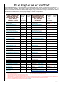
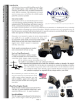
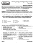
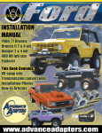
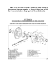
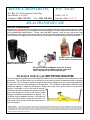
ADVANCE ADAPTERS INC.
P/N: ATLAS
P.O. Box 247, 4320 Aerotech Center Way
Paso Robles, CA 93447
Telephone: (800) 350-2223
Fax: (805) 238-4201
PAGE 1 OF 11
Page Rev. Date: 09-21-15
ATLAS TRANSFER CASE
THIS UNIT IS SHIPPED DRY!
All open holes are plugged on the new Atlas case with red plastic caps only to keep contaminates out. When
unpacking, inspect for any lost or damaged items during shipping. All Atlas transfer cases are hand-built to
your predetermined specifications. Please verify that ALL features, such as input spline and case
configurations (left or right hand drop), are correct. We have included a application chart on the next page for
your reference. If changing a yoke or checking your yoke options, see the last page of this instructions.
Amsoil is the recommened oil
for the Atlas 2 & 4 speed units
We offer several billet aluminum
shifter knobs in 5 colors
We offer an Atlas installation kit for the 2 and 4
speed transfer cases. Which includes a new vent
hose, vent and oil for the first oil change.
The universal drivetrain jack GREAT FOR ATLAS INSTALLATIONS
This new patented drivetrain jack is for anybody that works on their own vehicles as well as shop owners and
mechanics. The Uni-Raise allows you to remove the stock skid pan and/or crossmember while it supports
the drivetrain. The Uni-Raise is versatile enough for the avid four wheeler to do on-the-spot trail repairs safe
& simple, as well as the shop mechanic for his daily work. The Uni-Raise is adjustable to different frame
widths and capable of supporting 600 pounds. Rather than using a floor jack to support your drivetrain
making it impossible to move the vehicle around if
needed, the Uni-Raise supports the drivetrain from the
frame rails allowing you to move the vehicle without
having to reinstall the crossmember for support. The
Uni-Raise can be installed in minutes. Just adjust the
unit to your frame width, connect the hooks to your
frame, and center the jack under the transmission or
rear of the engine.
SPECIAL NOTE:
The components packaged in this kit have been assembled and machined for specific type of conversions. Modifications to any of the components
will void any possible warranty or return privileges. If you do not fully understand modifications or changes that will be required to complete your conversion, we strongly
recommend that you contact our sales department for more information. This instruction sheet is only to be used for the assembly of Advance Adapter components. We
recommend that a service manual pertaining to your vehicle be obtained for specific torque values, wiring diagrams and other related equipment. These manuals are normally
available at automotive dealerships and parts stores.
Atlas Adapter Selection Chart
The information listed below is to aid in the selection of the proper Atlas transfer case for the transmission you've selected. On
certain transmission applications, we've listed a couple of options when coupling the transmission to the transfer case. The
different options usually come about from different adapter lengths, giving you the choice for a longer or shorter drivetrain. With the
diversity of adapters we offer, we could actually offer up to 5 or 6 ways to couple some of the different transmissions to the 11
different Atlas input shafts; however, we are trying to simplify the choices and applications.
ATLAS TRANSFER CASE
ADAPTER SELECTION
CHART FOR GM, FORD,
JEEP & DODGE
MANUAL & AUTO
TRANSMISSIONS
GM SM420 4 SPEED
10.5" CASE LENGTH
GM SM465 4WD 10 SPL.
12" CASE LENGTH
GM SM465 2WD 35 SPL.
12" CASE LENGTH (NOTE 9)
FORD T & C 4 SPEED O.D.
ADAPTER KIT,
ATLAS INPUT
ADAPTER
SPLINE
HOUSING
OR
STOCK HOUSING
50-9702 (2)
23
10
35
31 OR 28
10.25" CASE LENGTH (4WD trans)
FORD & JEEP T98 4 SPEED
11.87" CASE LENGTH
JEEP T18 4 SPEED
11.87" CASE LENGTH
FORD T18 4 SPEED
11.87" CASE LENGTH
FORD T19 4 SPEED
11.87" CASE LENGTH
FORD NP435 4 SPEED
10.87" CASE LENGTH
1980 to 1986 STOCK
JEEP TRANSMISSIONS
1987& NEWER STOCK
JEEP TRANS 21 SPL. OR 23 SPL.
GM NV4500 4WD 32 SPL.
12.375" CASE LENGTH
DODGE NV4500 4WD 23 SPL.
12.375 CASE LENGTH
DODGE NV4500 4WD 29 SPL.
GM TH400 2WD TRANS.
ADAPTER KIT,
ATLAS INPUT
ADAPTER
SPLINE
HOUSING
OR
STOCK HOUSING
50-6300 (2,3)
50-6802 (3)
50-6304 (2)
AS-6800 (5)
51-6400
(4)
23
23
23
27
32
AS-6401
(5)
32
AS-6401 &
AS-0404 (5)
51-6408
32
SHAFT STICKOUT OF 5" (NOTE 9)
3.5" ADAPTER
STOCK (5,8)
GM TH350 4WD TRANS.
21.5" CASE LENGTH
3.5" ADAPTER
51-9807 (4,7)
GM TH350 2WD TRANS.
21.5" CASE LENGTH
5.25" ADAP.
51-9807 (7)
ATLAS TRANSFER CASE
ADAPTER SELECTION
CHART FOR GM, FORD,
JEEP & DODGE
AUTOMATIC
TRANSMISSIONS
GM TH400 4WD TRANS.
SHAFT STICKOUT OF 1.5" (NOTE 9)
50-7503 (3,7)
23
50-7502 (3,7)
23
23
3.25" ADAP.
52-6501(3,8,7)
51-7500
50-3801(3,8,7)
27
23
23
(5,7)
50-9102 (3)
23
AS-9111
27
(5)
50-0404 (3)
23
GM 4L60E 4WD TRANS.
AS-9111
27
23.375" CASE LENGTH
(5,10)
GM 4L60E 2WD
29
GM 6L80 6L90
50-0405 & E
50-9102 (3)
50-0405 & E
AS-9111
50-9300 (3)
50-9305 (3)
50-9600
31
FORD C4 3 SPEED TRANS.
STOCK
21 OR 23
W / REMOVABLE BELLHOUSING
32
GM 4L60E 4WD TRANS.
W / REMOVABLE BELLHOUSING
23
GM 4L60E 4WD TRANS. SHORTY
W / REMOVABLE BELLHOUSING
6.3" ADAPTER
STOCK
GM 700R / 4L60 O/D 4 SPEED
23.375" CASE LENGTH 2WD TRANS
GM 700R / 4L60 O/D 4 SPEED
23.375" CASE 4WD TRANS
GM 4L60E 2WD & 4WD
32
(5)
23.375" CASE LENGTH
4.25" ADAP.
STOCK
ADAPTER
STOCK (7)
ADAPTER
51-0205 (5)
51-0220
STOCK (5,7)
GM 4L80 & 4L80E 4SP TRANS.
USE GM 4WD SHAFT (NOTE 9)
3.25" ADAP.
50-7500 (3,8,7)
GM TH400 4WD TRANS.
SHAFT STICKOUT OF 2.5" (NOTE 9)
3.25" ADAP.
23
27
23
32 or 29
6.3" ADAPTER
FORD ZF 4WD TRANS.
STOCK
(1,5,7)
(5,8)
28
50-8100 (3)
23
50-2903/2905
SEE PAGE 14
STOCK (1,5,7)
50-2902 (3,7)
STOCK (1,5,7)
50-2901 (3,7)
STOCK (1,5,7)
27
29
31
23
31
23
31
STOCK (5)
STOCK (1,5)
25
21 or 23
REPLACING A BRONCO DANA 20
GM MUNCIE 4 SPEED
50-6000 (2,3,7)
23
10" CASE LENGTH
GM ZF 6SP S6-650 TRANS
TACOMA TRANS 23 SPLINE
TACOMA TRANS 26 SPLINE
POWERGLIDE (automatic)
Toyota Crawler Box
to Atlas Case
2012 & Newer JEEP
AUTOMATICS
2012 & Newer JEEP
Manuals
(1)
(2)
(4)
(6)
(7)
(8)
(9)
(10)
FORD C4 3 SPEED TRANS.
ALL OTHER VEHICLES
50-5710
50-5711
50-9200
29
23 short
23 short
27
50-5915
STOCK
23
26
STOCK
23
SHORTY C4 FORD TRANS.
ALLISON 1000 TRANS.
FORD AOD EARLY 4SP 4WD
1987 & EARLIER
2WD TRANS
FORD AOD LATE 4 SP 4WD
1988 & UP
2WD TRANS
FORD C6 3 SP. TRANS.
20" CASE LENGTH
FORD EXPLORER/RANGER/BRONCO II
1980-11 JEEP AUTOMATICS
OUTPUT SHAFT MAY NEED TO BE SHORTENED OR A SPACER ADAPTER MAY NEED TO BE USED. AS-0404 - 1” AS-8603 - 3/4” AS-8610 - 1/2”
THIS KIT USES A SPUD SHAFT
(3)
NEW OUTPUT SHAFT MUST BE INSTALLED
USES A STOCK 2WD OUTPUT SHAFT
(5)
USES A STOCK 4WD OUTPUT SHAFT
THIS KIT SHOULD BE USED IN CONJUNCTION WITH A 700R KIT
THE CASTING IN THIS KIT ONLY HAS ONE ROTATION AVAILABLE
THIS TRANSMISSION, IF CURRENTLY ADAPTED TO A BRONCO DANA 20 TRANSFER CASE, CAN USE AN ATLAS 28 SPLINE TRANSFER CASE AS A DIRECT BOLT
UP TO THE TRANSMISSION ADAPTER.
THE OUTPUT SHAFT MUST BE SHORTENED TO BE A FLUSH STICKOUT WITH THE BACK SIDE OF THE ADAPTER HOUSING.
A RELUCTOR RING AND SENSOR KIT MUST BE PURCHASED, P/N 716073
page 2
Installation Procedures
For All Vehicles
Before the actual installation begins, you should read the installation and operating procedures of your new
transfer case. Please verify that ALL features such as input spline and case configuration (left or right hand drop)
are correct. Also inspect the unit for any damage that may have occurred during shipping. This section of the
manual deals with the general installation procedures of the Atlas. Specific installation instructions for many
vehicles are also on our website at www.Advanceadapters.com or provided for you with your unit. Please read
all instructions before installing.
LUBRICATION
This unit is shipped DRY. Before operating your Atlas, please fill with the recommended gear
lubricant (Amsoil MTG GL-4, Torco MTF GL-4, or any other A.P.I. GL-4 rated synthetic gear oil). If you
are unable to find these lubricants, Any 75-90w synthetic GL-4 rated oil will work. On the Atlas HD applications,
we are now recommending Amsoil SAE 190.
The recommended oil capacity is 2 quarts in the Atlas 2 speed and 2-1/2 quarts for the Atlas
speed transfer case. The Atlas does not offer any type of ‘weep hole’ to verify the oil
level. Therefore, we have supplied your unit with a site tube to aid in determining the
correct fluid level. Once the required two quarts are put into the Atlas, we
recommend marking the oil level on the site tube. We like to use a small zip tie
a oil level marking device. Note: When the Atlas is overfilled beyond the
recommended levels, it will cause the unit to vent the extra oil out the breather.
4
as
PREPARATION
Now is a good time to familiarize yourself with the shifter
components. Pre-assembly of the shifter items will help a
great deal with the final installation. Unpack the shifter and install
the shifter base. Use RTV Blue silicone to seal the bolt threads. Pre-assemble
the rest of the components. Detailed shifter assembly instructions can be found
in The Final Installation section. Once the shifter has been properly setup, remove
it from the transfer case (leaving the triangular 3 bolt base on the unit). The Atlas
must be installed into the vehicle without the shifters attached. On Atlas 4 speed units, the cable shifter on the
reduction housing must be installed before installing the Atlas into your vehicle.
page 3
A normal installation of the Atlas transfer case should take around 6 to 8 hours. Before
disassembling your vehicle, the undercarriage should be cleaned to aid in the
installation process. Stock driveline lengths should be measured with
your vehicle on the ground. The measurement should be taken
as illustrated on Fig. B. Retain these measurements for
later use.
The Atlas offers up to 4 different rotations depending on the application. We offer the same
(Fig. B)
rotation as stock on all units. The other rotations
are provided for either additional ground clearance
or unique applications. Vehicles using one of our
adapters with the dual bolt patterns have 8 rotation
options. Before removing your stock transfer case, an angle finder can be used to obtain the rotation of your stock
transfer case.
Your vehicle can now be raised for the necessary removal of the driveshafts, skid pan, and the stock transfer
case. Note: Please make sure your vehicle is supported securely!
Recommended Equipment: A floor jack to support the tranny and engine when the
crossmember is removed, and a transmission jack for raising and lowering the
transfer cases. The Advance Adapters Uni-Raise (shown left, P/N 15-1000) is also a
helpful tool when doing drivetrain work.
By unbolting and removing your stock transfer case, you should have your
transfer case adapter and output shaft exposed. The adapter housing
transfer case mating flange should be cleaned of any debris. Double check
the output shaft splines of your transmission and verify the stickout length.
Make sure the Atlas has the same spline and that the length of the
transmission output isn’t too long for the Atlas input. (Refer to the Atlas Input Shaft
section for more information).
The Atlas should now be test-fitted into the vehicle. The Atlas should index onto the spline of your transmission
and up to the adapter housing. While holding the Atlas securely in place, rotate the transfer case to the desired
rotation for your vehicle. Locate a stock hole on the adapter housing. Using a marker, mark the outside of the
Atlas index ring. This will help to identify the rotation pattern. Check for tunnel clearance, front driveshaft
clearance, and shifter clearance with the Atlas in this new rotation. Note: On many of the YJ, TJ, and CJ vehicles,
a minor modification to the tunnel area will allow you to mount the Atlas at a higher rotation with little or no
crossmember modifications. (Refer to the specific vehicle application for more details at www.advanceadapters.com).
Once this is done, remove the Atlas from the vehicle. Locate the mark on the index ring of the Atlas transfer case.
The bolt patterns on the transfer case index ring are relative. In other words, whatever hole you've selected will
be the same all the way around the index ring. Using the stud bolts provided, install them in the chosen pattern
rotation. These studs are stock New Process items and are a restrictive fit into the front of the Atlas. If you are
using a spacer adapter that requires longer bolts or stud bolts, they should be installed using 242 Loctite. Install
the studs so that they have full thread engagement in the transfer case adapter ring. DO NOT PRELOAD THE
STUDS INTO THE ATLAS INPUT RING!
TIP: Before the final bolt up, we have found it easier to equip the Atlas with all the necessary components. For
example: Shift indicator switch, speedometer, site tube, and drain plug, etc. The Atlas is also shipped with
numerous red plastic caps to keep contaminates out of the unit. At this point in time, remove all caps and properly
install all components.
page 4
The Final Installation
Apply a very thin film of RTV Blue silicone to your transfer case adapter mating surface. Aligning the studs with the
adapter holes and the transmission output shaft with the Atlas input, the Atlas should slide completely onto the
transmission mating surface. There should not be any GAP between the two units! If they do not meet, then you
have an interference problem! Refer to the Atlas Input Shaft section for the recommended transmission shaft
lengths. DO NOT PULL THE TWO UNITS TOGETHER WITH THE FASTENERS. This will cause internal damage
to the unit. Possible problems may be too long of an output shaft or on some Jeep 21 & 23 spline transmissions,
a spacer adapter may be necessary. If you are in doubt regarding your interference problem, please call!
The recommended nuts have been provided to secure the Atlas to your adapter. With the Atlas now secure, check
again for proper clearances such as driveshaft, floorboard, skid pan, and exhaust, etc.
DRIVELINE MODIFICATIONS
You will normally need driveline modifications when installing the Atlas transfer case. What we have found that
works well is either adding or subtracting (depending on the application) the measurements of the Atlas from
the stock length of your transfer case.
REAR MEASUREMENT: To determine the new length for the rear driveline,
(Fig. C)
simply measure from the face of the transfer case to the face of the rear
output yoke (Fig. C). Write that measurement down.
Take the same type of measurement of the Atlas. With that in mind,
consider the following example.
Rear Measurement Example (Fig. C): This stock transfer case measured (on our example) 16.8". When subtracting that measurement from the Atlas measurement of 13.8", you
have a difference of 3.0". Since the Atlas is 3.0" shorter than your stock transfer case, your rear driveshaft would
then need to be lengthened 3.0". This difference is now added to the measurement taken from your stock
driveline, as recommended in the Preparation section. You would now have your new rear driveshaft length.
FRONT MEASUREMENT: Measure the stock transfer case from the front yoke face
to the surface of where the transfer case bolts to the adapter housing (Fig. D). Write
that measurement down.
The front yoke on the various stock transfer cases can either be a positive measurement (protrudes out from the adapter input face), or a negative measurement
(recessed inward from the adapter input
face). Most gear-driven transfer cases
will have a positive yoke measurement,
(Fig. D)
and most chain-driven transfer cases
will have a negative yoke measurement.
The Atlas measures approximately 2" positive offset from the face
of the front yoke to the transmission adapter input.
Front Measurement Example (Fig. D): This stock transfer case (our Stock driveshaft (top) vs. new fixed yoke driveshafts
example) measured a negative 1-1/4”. Adding that to the Atlas
measurement of positive 2”, the difference is 3-1/4”. Since the Atlas front yoke on this application is 3-1/4” closer
to your front axle, you would then need to shorten your front driveshaft this distance. This difference can now be
page 5
BREATHER INSTALLATION:
The stock transfer case breather hose should be replaced with a 3/8" fuel hose and connected to the brass elbow
located on top of the Atlas. A new breather should be installed on the opposite end of this hose and mounted to
the firewall. A free flowing atmospheric breather typically found in earlier model vehicles or used on differentials
is best. On later model Jeeps, the stock breather is very restrictive. This stock breather is for lighter viscosity oils
such as the ATF used in the stock transfer case. If this breather is not replaced, oil will blow out into the engine
compartment. We offer new breather kits for the 2 and 4 speed cases.
SPEEDOMETER INSTALLATION:
We can supply a cable-type speedometer drive unit for all applications other than Jeeps 1982 to current. The 1982
and newer Jeeps will use the original speedometer drive that came stock. You will simply have to remove it from
your New Process transfer case and install it into your new Atlas. It is recommended that you replace the o-ring and
seal that we have included with the Atlas package. On older Broncos, Bronco IIs, Explorers and Rangers, a
speedometer cable fitting adapter must used to connect the Atlas speedometer drive to your speedometer cable.
Nevada Speedometer (Ph# 775-358-7422) should have the necessary parts to assist you in this manner. The newest
Jeep that used a New Process 241 transfer case picked up the speed from the axles, and the speedometer hole
in the Atlas can be plugged.
On engine converted vehicles, caution should be used. If your engine has been converted to a newer Chevy, Ford
or Chrysler and is computer controlled, it may also require a vehicle speed sensor. The speed sensor is usually
connected at the speedometer. Each manufacturer has designed their own unique way of obtaining this computer
input. If your vehicle has any computer requirements, you will need to take this into consideration. If you are wanting
to install the Atlas into a Chevy, Ford or Chrysler vehicle, the computer requirements mentioned will also apply. Once
you've taken into consideration your specific requirements, the speedometer cable can now be connected.
Speedometer Calibration: There are two factors that affect your speedometer reading; actual tire diameter and axle
gear ratio. The actual tire diameter is usually different than what is printed on the side wall of your tire. For example:
A 33 x 11.5 x 15 tire (depending on the brand), may actually measure 32.5" in diameter. Tire sizes vary greatly among
the manufacturers. Even the same tire from the same manufacturer can vary as much as 7% in diameter.
The speedometer chart below will assist you in obtaining the right speedometer
drive gear. As you can see their are two types of speedometer gears, both long
and short. We measured them by the overall length of the speedometer gear.
Long being 4.3" and short being 2.2". The speedometer housings that accept
these gears are not interchangeable. For example: If your stock vehicle had a 2.2"
gear, you cannot put a 4.3" gear onto that speed-o-drive housing.
If you are installing an Atlas in a 1987 or newer Jeep and have not changed your
tire size or your axles, your stock speedometer drive gear would remain the
same. We offer many stock gear options for your speedometer housing.
44”
42”
40”
39”
38”
37"
36”
35"
33"
32"
31"
30"
29"
28"
5.38
33T
35T
36T
37T
38T
39T
40T
42T
5.13
32T
33T
35T
36T
36T
37T
39T
40T
43T
4.88
30T
31T
33T
34T
35T
36T
37T
38T
40T
41T
43T
4.56
28T
29T
31T
32T
32T
33T
34T
35T
37T
39T
40T
41T
43T
4.10
3.73
3.55
3.07
28T
28T
29T
30T
31T
32T
34T
35T
36T
37T
38T
40T
26T
27T
27T
28T
29T
31T
32T
33T
34T
35T
36T
26T
27T
28T
29T
30T
31T
32T
33T
34T
26T
27T
28T
29T
30T
Short
Electronic-type
Long Cable-type
When installing a speedometer gear
with either 39, 40, 41 or 42 teeth, the
gear and the housing must be installed
separately. These are all large diameter speedometer gears. By first installing the gear into the tailhousing
you will be able to tilt the gear shaft up
allowing you to position the gear past
the Atlas output shaft. Once this gear
is in place, the speedometer housing
must be aligned with the speedometer gear shaft and indexed into the
tailhousing. When installing the
speedometer housing, lube the o-ring
that contacts the Atlas tailhousing with
a bit of oil. This will prevent the o-ring
from being nicked upon installation or
rotation, causing this housing to leak.
page 6
Speedometer Problems: No matter what speedometer gear you use, you must make sure that the teeth of the
speedometer gear have proper contact with the Atlas output shaft. The speedometer housing can be rotated to
achieve proper contact. Note: There are three rotation possibilities. Many of the Jeep speedometer housings offer
index numbers that reference to the gear tooth count. By lining up the retainer clip with the proper index number,
the speedometer gear will work properly. If your housing does not have these index numbers, proper engagement
can be obtained by rotating the speedometer housing until the speedometer gear meshes with the output shaft.
The slots on the housing will then line up with the retainer clip. If this is not done, the speedometer will not engage
properly.
TJ Speedometer Installation: The Jeep TJ speedometer is a tight clearance fit to the Atlas
shift control. One option for clearance is to plug in the connector while the speedometer
is rotated away from the shift control, and then rotate the assembly back into position for
the speedometer gear engagement. The other option is to keep the white portion of the
speedometer rotated 180 degrees from where it would normally be and use a washer
under the bolt head to retain this part of the speedometer in place.
SHIFT INDICATOR:
The transfer case shift indicator (if applicable) should be connected. Make sure wires and/or hoses have proper
body clearance and are not bound in any way. For more information, see the specific vehicles applications.
DRIVESHAFTS & CROSSMEMBER / SKID PAN:
You should now install your modified driveshafts. Trial fit your crossmember or skid pan, noting any modifications
that may be necessary. The Atlas is equipped with a drain plug located on the inspection cover. You may wish
to cut an access hole in your crossmember/skid plate for easy access. Once the modifications are made, install
the crossmember/skid plate securely to the frame and the rubber support to the crossmember/skid plate.
LUBRICATION:
Before lowering your vehicle, fill your Atlas with the oil provided (Amsoil MTG GL-4, Torco MTF GL-4). By using
a hand pump, connect the hose end to the upper fitting of the site tube to fill the Atlas to the recommended oil level.
Once this is completed, re-secure the upper site tube fitting to the Atlas. If you are unable to find these lubricants
locally, we offer it under P/N 303200.
VISUAL INSPECTION:
Once the vehicle is back on the ground, the transfer case area should be inspected to verify that all fasteners and
components relating to the transfer case are properly attached.
A visual inspection should be made with regard to driveline angles and clearance. New and unwanted noises are
most often related to poor driveshaft angles! C.V. driveshaft combinations must be set so that the differential yokes
are in-line with the driveshaft under normal operating load. Non-C.V. driveshaft combinations must be set so that
the pinion yoke angles match the transfer case output yoke angles under normal operating load. Remember to
allow for (spring wrap) if you have leaf springs. The front pinion will dive downward under load and the rear pinion
will rise upward. There are many different spring rates on the market, so this may take some tweaking to eliminate
a poor driveshaft condition. (For examples, see photos below). The Atlas transfer case is a close tolerance design.
If you feel any vibration at all in the shift handles, suspect improper driveshaft angles!
Rear (too low).
Will not raise enough for C.V.!
Rear (correct).
Perfect for C.V.
page 7
COMMON Installation MISTAKES
This section highlights a few of the areas that we commonly see mistakes made during the installation of an Atlas 2 and 4 speed. These
mistakes will cost you time and money. Most problems occur because the installation is rushed or procedures overlooked. Other errors
happen because the instructions were not read or followed.
The most common mistake is having a transmission output shaft that is too long or
does not have long enough splines. A shaft that has either one of these problems
can bottom out or not engage enough into the Atlas input. Most times, this interference is not noticed until the transfer case is being installed. Most installers get
the transfer case near to the mating flange, but find they are lacking roughly 1/16 of
an inch between the two gear boxes coming together. They push, pull & rotate to
mate the two boxes, then decide to put the nuts on the stud of the transfer case to
pull the units together. The transfer case, whether being a 2 speed or 4 speed, is
now damaged: the 2 speed having a broken front housing snap ring, and the cage
needle bearing of the 4 speed having been pre-loaded. Running the units in this
state will cause complete destruction of the unit. In short, both units will need
disassembly to fix the problem.
The easiest fix is prevention. If the gear boxes do not slide together completely when installing, remove the transfer case and measure
the shaft lengths. Refer back to this application guide to the input section for spline engagement lengths. The Atlas is a precision built
transfer case. DO NOT FORCE TOGETHER even if it’s a small gap between the transmission and transfer case.
The second, most common mistake or problem is the cable shifter adjustments and installation. We now offer several custom and
universal cable shifters to fit the Atlas 2 and 4 speed transfer cases. The instructions highly recommend installing the shifters to the
Atlas while the transfer case is outside the vehicle. This will allow you the opportunity to fine tune the linkage while viewing the
movement of both the handle and the shift rail. Adjustments to the linkage could be a half turn of a certain nut. If the Atlas & shifters
are installed, that nut is hard to get a wrench on and you could spend a lot of time trying to get it adjusted correctly. Incorrect
adjustments to the linkage will make the Atlas hard to shift, and we have seen some cables actually break because of driver trying to
force a mis-adjusted shifter.
The last area of concern is more of a precaution, not an installation mistake. After an Atlas was installed, we have seen a couple of
transfer cases that have experienced rear output shaft bearing failure. The Timkin bearings require custom shimming for each Atlas
built. The tolerance is .001” which is the recommendation from Timkin. The units we’ve seen failure on have been new installations
(having less than 10 to 20 miles on the unit) and in a vehicle that was flat-towed. We now recommend that a new unit must have the
break-in fluid replaced, which is after the first 500 driving miles. This allows the bearing to seat properly to the bearing race. It also
allows the oil to circulate through the unit to lubricate areas that were assembled with assembly lube. If you plan on flat-towing, we
actually prefer that you remove the driveshafts from the vehicle. This eliminates any possible chance of bearing failure on your Atlas
2 speed due to lack of oil circulation. PLEASE NOTE that under absolutely no circumstance should an Atlas 4 speed be flat-towed
without removing the driveshafts. Damage to the planetary assembly and the additional needle bearings will occur.
1.
2.
3.
4.
5.
6.
7.
8.
THINGS YOU SHOULD KNOW ABOUT YOUR ATLAS
DO NOT disassemble the unit! Disassembly of the unit will void your warranty.
We have had a few customers that have disassembled their Atlas transfer case. One mistake commonly made is the
reassembly of the unit. The tailhousing on the Atlas is a component that must be shimmed properly in order for the
unit to operate properly. When reinstalling the tailhousing, most individuals use a silicone sealant which changes the
end play on the Atlas and will cause internal problems.
Proper support of the Atlas and transmission with a support mount that is in good shape is recommended.
Check the yoke nut torque specifications periodically. The yoke nuts should be torqued at 150 ft./lbs.
It is twice as hard to shift the transfer case if the vehicle is not at least slowly rolling forward. In addition, trying to shift
the transfer case while the wheels are turned puts a bind on the synchronizers, making it almost impossible to shift in
or out of gear.
Layout and inventory all parts. Test fit before starting the installation. Verify the configuration of your Atlas.
Give ample clearance between the Atlas and the body. The shifters also need to have complete free
range of motion.
We have found that driveline angles are responsible for 99.9% of all noises that “seem” to be coming from
the Atlas.
page 8
Operating Your New Atlas
The Atlas has internal shifter interlocks that prevent the unit from being mis-shifted.
The knobs on the Atlas Twin Stick are to assist you with identifying the rear output
and the front output.
For 2WD High in which the vehicle should first be tested, the knob labeled "Rear" will be in the high
position and the "Front" knob should be in the neutral position. After a few miles in 2WD High, we
recommend that you shift the "Front" shifter knob into High, putting you in 4WD High. (On manual locking hubs, to
achieve any type of 4WD your hubs must be locked). The "Front" shifter handle should shift smoothly in and out
of neutral and High. IF THE SHIFTER DOES NOT ENGAGE EASILY, DO NOT FORCE IT. (Your linkage my need
to be adjusted). When you are shifting out of 4WD high, the "Front" knob must always be disengaged first. If the
shifter feels tight or sticky, press in the clutch or shift to neutral (automatic transmission), or simply straighten the
front wheels. The vehicle should be moving forward when shifting the Atlas.
When shifting into Low range, REMEMBER the following: The vehicle should be at a slow roll forward, no faster
than 5 miles an hour. Speeds faster than recommended could cause personal injury (like unloading the
rear payload into the front seats!), or damage to the drivetrain (which is not only embarrassing but
expensive!). The Atlas has the unique feature of 2WD low with the rear axle or the front axle. At any time while
driving in low ratio, you can disengage either the front or rear by shifting the respective handle into neutral.
Shifting an Atlas with an Automatic transmission: While the vehicle is slowly moving forward, place the
transmission into neutral and engage the front or rear control into Low. The Atlas is a synchronized shift design
which means synchro sets have been added to SPEED MATCH the gear and shaft relationship. If you are
stopped with no forward motion and the unit will not shift, place the transmission in Drive or Reverse then back
to neutral, then attempt to shift the Atlas. DO NOT FORCE THE ATLAS INTO GEAR.
Shifting an Atlas with an Manual transmission: While the vehicle is slowly moving forward, depress the clutch
and engage the front or rear control into Low. DO NOT FORCE THE ATLAS INTO GEAR or HOLD PRESSURE
ON THE SHIFT LEVERS WHILE RELEASING THE CLUTCH.
As you become accustom to the operations of the Atlas and the unit accumulates miles, the shifting will become
easier.
TWIN STICK SHIFT POSITIONS
Neutral:
2WD High:
4WD High:
4WD Low:
Both the "rear" and "front" knobs in the "N" position.
The "rear" knob in "H" position and the "front" knob in "N" position.
The "rear" knob in "H" position and the "front" knob in "H" position.
The "rear" knob in "L" position and the "front" knob in "L" position.
2WD Low:
(Rear Drive ONLY) The "rear" knob in "L" position and the "front" knob in "N" position.
*(Front Drive ONLY) The "rear" knob in "N" position and the "front" knob in "L" position.
*Special Note: With the front in 2WD low, the torque is distributed 100% to the front axle. Combined with the low gearing
in the transfer case, these factors can cause undue strain on your front axles. This should only be used for quick tight turns
in loose soil conditions. The only shift position that is not available is Front 2WD high.
4 Speed Atlas Reduction Housing: This is a non-synchronized shifted unit. To shift the reduction housing portion
of the Atlas, the vehicle should come to a complete stop and the transmission must be in a neutral position. Once
the vehicle is stopped, you can then engage or disengage the planetary gearing. The shifting of this unit is
designed for a cable shifter.
page 9
Operating Considerations
The low gear reduction of the transfer case will help to ease you through the toughest terrain you can find. The
essentials of good 4-wheeling is the sheer ability to maneuver at a safe speed while retaining your line of attack on
the course in front of you. The slower rate of approach will not only keep you in the seat, but also keep the tires
on the ground for the best possible performance.
If you are considering the Atlas or have purchased one already, it is sure to change the way you 4-wheel.
KNOW YOUR LIMITS!
Please begin with mild terrain and experiment safely to your new level of potential.
The low reduction will not only slow you to a tactical approach, but will also increase the expected output of your
current equipment. Your response from the accelerator may surprise you. The crawl ratio is a torque multiplication.
In some transfer case replacements, it can be an increase of more than twice that of the original potential.
KEY CONSIDERATIONS:
Brakes: On flat ground, with the brakes applied and the transfer case in low, you will notice deeper squat in the
suspension as you shift your automatic transmission into gear. If you have large disk brakes (front and rear), you
will be well equipped to control the increase in torque. If you have drum brakes or a set of stock vehicle brakes (front
and rear), you might find it hard to stop the vehicle when the transfer case is in its low range gear. There are many
aftermarket brake upgrade kits out on the market. For serious off-roading, this upgrade should be considered.
Differentials: You are sure to find your weakest link! If you are not sure about the capacity of your current
equipment, you may want to consult with an expert in this field! Research any 4WD magazine for the various sources
of manufacturers and distributors.
TOWING
The ATLAS 2 speed has been flat-towed for a distance of 300 miles and no problems were encountered. At this
time, we can only recommend flat-towing at this maximum distance. After 300 miles of travel, the vehicle should be
started. With the transmission in gear and the Atlas in neutral, let the vehicle idle for 5-10 minutes. This will circulate
the oil in the Atlas and allow for proper lubrication. We recommend that the Atlas should have at least 500 driving
miles on it before you flat-tow, allowing the bearings to break in.
When a vehicle is being towed with the Atlas 2 speed, both shift levers should be in the Neutral position. Our
experience regarding the transmission towing position are as follows (please also verify in your owners manual what
the vehicle manufacturer recommends):
Automatic transmissions should be left in park
/
Manual transmissions should be left in any gear
If you plan on flat-towing an Atlas 2 speed equipped vehicle and do not wish to stop to circulate the oil, we actually
prefer that you remove the driveshafts from the vehicle. This will prevent any damage that may occur to the
internal components due to lack of normal oil circulation.
The ATLAS 4 speed should never be flat-towed without removing the driveshafts. The planetary unit and
additional bearings do not receive the normal oil flow as they would under normal driving conditions and, therefore,
damage will occur.
MAINTENANCE
Atlas oil levels should be monitored frequently. The oil site tube should be marked with a zip tie to indicate proper
oil level for the Atlas at the rotation installed in your vehicle. The oil should be drained and replaced after the first
500 miles and then at intervals of 10,000 to 15,000 miles. Note: If your primary use is extreme offroading, you may
consider intervals as frequent as every engine service.
page 10
Yoke Options And Interchangeable Yokes
Yoke Series & Spline
32 Spline Yokes:
1310
1330
1310
1350
1350
1410
1410
series
series
series
series
series
series
series
Yoke P/N’s for
A New Atlas:
(C.V.)
(C.V.)
(non-C.V.)
(non-C.V.)
(C.V.)
(non-C.V.)Straps
(non-C.V.)U-bolt
Flange Yokes 32 Spline
1310/1330/1350 series
(CV & non-C.V.)
1410 series (non-C.V.)
P/N A1310CV
P/N A1330CV
P/N A1310
P/N A1350
P/N A1350CV
P/N A1410
P/N A1410U
Individual
Yokes:
P/N
P/N
P/N
P/N
P/N
P/N
P/N
300475
300369
716295
300472
300485
300483
300488
AA Seal
P/N’s
P/N
P/N
P/N
P/N
P/N
P/N
P/N
O.E. Seal
P/N’s
300502
300502
300473
300473
300473
300473
300473
CR 18817 or
NAT.473239
CR 21164 or
NAT.472015
CR 21164 or
NAT.472015
P/N AF1300
P/N 300470
P/N 300473
CR 21164 or
P/N AF1410
P/N 300471
P/N 300473
NAT.472015
1410 Flange yoke is drilled and tapped for (4) 12mm x 1.25 bolts on a 3.75”diameter and has a 2.75” female index for
the mating yoke. The 1300 series flange yoke is shown below.
Companion yokes for the flange yokes listed above 1310, 1330 & 1350 C.V. and non-C.V. flange yoke. Spicer companion yoke numbers are as follows:
(1310 C.V., P/N 211229x), (1310 non-C.V., P/N 2-2-939), (1330 C.V. - P/N 211631x), (1330 non-C.V., P/N 2-2-1369), (1350
C.V., P/N 212024x), (1350 non-C.V., P/N 3-2-1579).
1410 non C.V. flange yoke. Spicer companion yoke number is 3-2-439 (1410 non-C.V.)
Yoke Modifications: Changing the style of yokes on the Atlas transfer case may require your new yoke to be modified.
When installed on an Atlas, the yoke will load up against a tapered roller bearing. Some yokes require a chamfer to be machined
to clearance the cage of this bearing. The yoke drawing below shows the required machining on these yokes.
NOTE: If you replace the front 26 spline yoke with any of the yokes listed, the nut that retains the yoke has a torque specification
of 130-135 ft.-lbs. When replacing the front or rear 32 spline yoke with any of the yokes listed above, the nut that retains the yoke
has a torque specifications of 150-155 ft.-lbs.
U-Joints
Spicer
series#
1310
1330
1350
1410
1480
“D”- Dia
of cap (in)
1.062”
1.062”
1.188”
1.188”
1.375”
“E”-width
across caps (in)
3.219”
3.625”
3.625”
4.188”
4.188”
Part#
(non-C.V.)
5-153X
5-213X
5-178X
5-160X
5-188X
Std Spicer
U-bolt Part
2-98-94X
3-94-58X
3-94-18X
3-94-18X
3-94-28X
male index
page 11