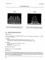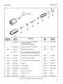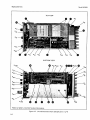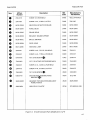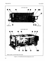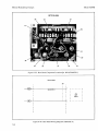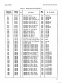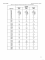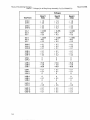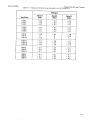
1
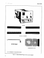
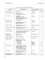
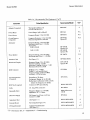
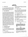
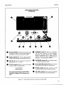
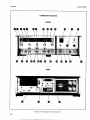
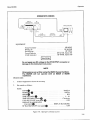
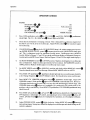
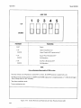
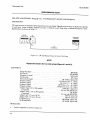
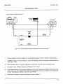
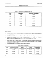
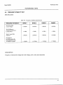
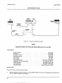
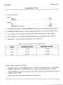
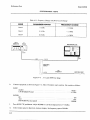
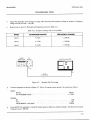
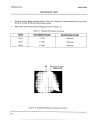
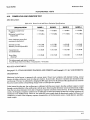
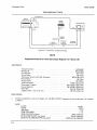
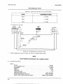
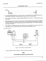
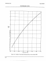
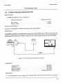
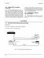
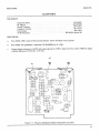
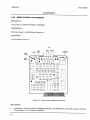
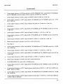
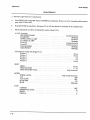
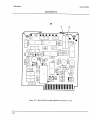
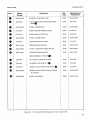
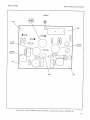
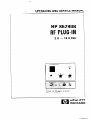
OPERATING
AND SERVICE MANUAL
.
HP 86290B
RF PLUG-IN
2.0 - 18.6 GHz
HEWLETT
PACKARD
COPYRIGHT AND DISCLAIMER NOTICE
Copyright - Agilent Technologies, Inc. Reproduced with the permission of Agilent
Technologies Inc. Agilent Technologies, Inc. makes no warranty of any kind with regard
to this material including, but not limited to, the implied warranties of merchantability
and fitness for a particular purpose. Agilent Technologies, Inc. is not liable for errors
contained herein or for incidental or consequential damages in connection with the
furnishing, performance, or use of this material or data.
CERTIFICATION
Hewlett-Packard Company certifies that this product met
from the factory. Hewlett-Packard further certlpes that
United States National Bureau of Standards to the extent
the calibration facilities of other International Standards
its published spec@ations gt the time of shipment
its calibration measurements are traceable to the
allowed by the Bureau’s calibration facility* and to
Organization members.
WARRANTY
This Hewlett-Packard
instrument product is warranted against defects in material and workmanship
for a period of one year from date of shipment
During the warranty period, Hewlett-Packard
Company will. at its option, either repair or replace products which prove to be defective.
For warranty service or repair, this product must be returned to a service facility designated by HP.
Buyer shall prepay shipping charges to HP and HP shall pay shipping charges to return the product
to Buyer. However. Buyer shall pay all shipping charges, duties, and taxes for products returned to
HP from another country.
HP warrants that its software and firmware designated by HP for use with an instrument will execute
its programming
instructions when properly installed on that instrument HP does not warrant that
the operation of the instrument
or software, or firmware will be uninterrupted
or error free.
LIMITATION
OF WARRANTY
The foregoing warranty shall not
maintenance by Buyer, Buyer-supplied
operation outside of the environmental
maintenance.
apply to defects resulting from improper
or inadequate
software or interfacing, unauthorized
modification or misuse.
specifications for the product or improper site preparation or
NO OTHER WARRANTY
IS EXPRESSED
OR IMPLIED.
HP SPECIFICALLY
DISCLAIMS
THE IMPLIED WARRANTIES
OF MERCHANTABILITY
AND FITNESS FOR A PARTICULAR
PURPOSE.
EXCLUSIVE
REMEDIES
THE REMEDIES
PROVIDED
HEREIN ARE BUYERS SOLE AND EXCLUSIVE
REMEDIES.
HP SHALL NOT BE LIABLE FOR ANY DIRECT, INDIRECT,
SPECIAL, INCIDENTAL
OR
CONSEQUENTIAL
DAMAGES. WHETHER
BASED ON CONTRACT, TORT. OR ANY OTHER
LEGAL THEORY.
ASSISTANCE
Product maintenance
Packard products.
agreements and other customer assistance agreements are available for Hewlett-
For any assistance, contact your nearest Hewlett-Packard
the back of this manual.
Sales and Service OfJce. Addresses are provided at
HP 86290B
RF PLUG-IN
(Including Options 004 and 005)
SERIAL NUMBERS
This manual applies directly to HP Model 86290B
RF Plug-In having serial number prelix 2227A.
With changes described in Section VII, this manual also
applies to instruments with serial numbers prefixed
1704A, 1727A, 1737A, 1742A, 1807A, 184OA, 1847A,
1852A, 1904A, 1908A, 1933A, 1952A, 2021A, 2034A,
2046A, 2109A, 2138A, and 2217A.
For additional information about serial numbers, refer
to INSTRUMENTS
COVERED BY MANUAL
in
Section I.
0 Copyright
1400
MANUAL
PART
Microfiche
Part
NUMBER:
Number:
FOUNTAINGROVE
HEWLE-IT-PACKARD
PARKWAY,
1984
COMPANY
SANTA
ROSA,
CA
95401
U.S.A.
86290-90074
86290-90076
Printed:
c?!a
JULY
1984
HEWLETT
PACKARD
Table of Contents
Model 86290B
CONTENTS
Page
Section
I
II
III
GENERAL
INFORMATION.
. . .. . . . . .. .
.....................
Introduction.
l-l.
Specifications ....................
l-6.
Safety Considerations.
..........
1-8.
l-10. Instruments Covered By Manual ...
......................
1-15. Description
1-19. Option 004. ......................
1-21. Option 005. ......................
l-23. Accessories Supplied. .............
l-25. Equipment Required But Not
Supplied ....................
l-27. Equipment Available. .............
l-28.
Service Accessories .............
l-30.
Reversing Extender Board. ......
RF Section 36-Pin Extender .....
l-32.
Model 8755C Swept Amplitude
l-34.
Analyzer. ...................
Power Meters and
l-36.
Crystal Detectors. ............
l-38.
Model 8410B/841 IA Network
Analyzer. ...................
l-40. Recommended Test Equipment
....
l-l
l-l
l-l
l-l
l-l
1-2
l-2
l-2
l-2
......................
INSTALLATION.
.....................
2-l.
Introduction.
2-3.
Initial Inspection .................
2-5. Preparation for Use. ..............
2-6.
Power Requirements. ...........
Interconnections
...............
2-8.
Mating Connectors .............
2-10.
Operating Environment.
........
2-12.
2-13.
Temperature.
..................
.....................
2-14.
Humidity,
2-15.
Altitude .......................
2-16.
Frequency Scale Installation. ....
2-18.
RF Plug-In Installation
and Removal ................
2-19.
Installation ....................
Removal. ......................
2-20.
2-21. Storage and Shipment. ............
Environment.
..................
2-22.
Packaging .....................
2-24.
Original Packaging. ............
2-25.
2-26.
Other Packaging ...............
2- 1
2-l
2-l
2-1
2-l
2-l
2-l
2-1
2-l
2-1
2-l
2-1
.......................
..
OPERATION
Introduction.
..................
..
3-l.
Panel
Features
................
.
.
3-3.
Operator’s
Checks
.............
.
.
3-5.
3-7. Operating Instructions
.........
..
3-8.
Internal Leveling. ...........
..
3-10.
External Power Meter Leveling. . . .
3-l
3-l
3-l
3-l
3-l
3-l
3-l
l-2
l-3
l-3
l-3
1-3
Section
External Crystal
Detector Leveling ............
3-14.
Internal AM ...................
3-16.
External AM. ..................
3-18.
External FM. ..................
3-20.
Frequency Response. ...........
Phase-Lock Operation ..........
3-22.
3-24.
X-Y Recorder Operation ........
3-29. X-Y Recorder Modilication
Kit. ....
3-3 1. Operator’s Maintenance ...........
3-12.
IV
l-3
l-3
l-3
l-3
2-3
2-3
2-4
2-4
2-4
2-4
2-4
2-5
Page
V
PERFORMANCE
TESTS ...............
Introduction.
.....................
4-l.
Equipment Required. .............
4-4.
4-6.
Test Record ......................
4-8. Frequency Range and
Accuracy Test ...............
4-9. Frequency Stability Test. ..........
4-10. Power Level and Variation Test ...
4-11. Residual AM Test ...............
4-12. Spurious Signals Test ............
4-13. Equivalent Source SWR Test. .....
4-14. External Frequency
Modulation
Test ............
4-15. Amplitude Modulation
Test. ......
3- 1
3-2
3-2
3-2
3-2
3-2
3-2
3-3
3-3
4-l
4- 1
4-l
4-l
4-l
4-7
4-13
4-18
4-20
4-21
4-25
4-28
ADJUSTMENTS
. . . . . . . _ . . . . . . . . . . . . . . . 5- 1
.....................
5-l.
Introduction,
5-1
5-3. Equipment Required. .............
5- 1
5-5. Factory Selected Components.
.....
5-l
Safety
Considerations
.............
5-7.
5- 1
5-13. Related Adjustments ..............
5-l
5-15. Abbreviated RF
Alignment Procedure. ........
5-6
5-17. Location of Test Points
and Adjustment. .............
5-6
5-19. Frequency Modulation
Balance Adjustments.
........
5-6
5-20. Sweep Control Adjustments. .......
5-8
5-21. Stop Sweep Adjustments. .........
5-10
5-22. YTO Frequency
Range Adjustments
.........
5-12
5-23. YTM Slow Speed
Tracking Adjustments .......
5-14
5-24. YTM Slow Speed Tracking Adjustments
(Alternate Procedure). .......
5-23
5-25. YTM Bias Control Adjustment.
... 5-28
5-26. YTM and YTO Delay Compensation
Adjustments.
...............
5-32
5-27. ALC Adjustments. ...............
5-37
5-28. Band Switch Overlap
Adjustments.
...............
5-47
i
Table of Contents
Model 86290B
CONTENTS
Section
Page
5-29.
5-30.
VI
Frequency Reference
Calibration Adjustment.
Frequency Modulation
Sensitivity Adjustment.
REPLACEMENT
PARTS.. .
6-1. Introduction.
. . . . . . .. .
6-3. Abbreviations
. . .. . . . .
6-5. Replaceable Parts List.
6-8. Parts Identification
...
6- 10. Ordering Instructions
.
(Cont’d)
Section
8-3. Assembly Service Sheets. . . . , . .
8-5. Safety . . . . . . . . . . . . . . . . . . . . . . .
.. . . .. . . .. . . ._
8-9. Troubleshooting
8-13. Recommended
Test Equipment
8-15. Repair. . . . . . . . . . . . . . . . . . . . . . .
8-16.
Band Indicator
Lamp Replacement.
. .. . .
Cleaning Switches. . . . . , . . . .
8-18.
8-20.
ALC Switch
Contact Detail. . . . . . . _ . . .
8-22.
Unleveled Lamp Removal
and Replacement . . . . . . . .
8-24.
RF Section Removal
and Installation. . . . . . . . . .
8-26.
Parts Locations, Test Points,
and Adjustments. . . . . . . .
. . . . . 5-53
. . . . . . 5-54
....
....
....
....
....
....
6-1
6-1
. . 6-l
. . 6-1
6-2
. . 6-2
..
..
..
..
..
VII
MANUAL
BACKDATING
CHANGES..
. 7-l
7-l.
Introduction.
. . . . . . . . . . . . . . . . . . . . . 7-1
VIII
SERVICE. .................
8-1. Introduction.
.........
...........
...........
8-l
8-l
Page
. ..
...
...
. ..
. ..
8-l
8-1
8-l
8-2
8-2
. . . . 8-2
. . . 8-2
. . . 8-2
. . . 8-2
. . . 8-3
. . . 8-3
ILLUSTRATIONS
Figure
l-l.
1-2.
l-3.
1-4.
l-5.
2-1.
2-2.
2-3.
3-l.
3-2.
3-3.
3-4.
3-5.
3-6.
3-7.
3-8.
3-9.
ii
Page
Model 86290B RF Plug-In with
Accessories Supplied . . . . . . . . . . _ . . . . . 1-O
Serial Number Plate . . . . . . . . . , . . _ . . . . . . l-l
Service Accessories, HP Part Number
08620-60124........................
l-10
Reversing Extender Board,
86290-60033........................
l-11
RF Section 36-Pin Extender,
08621-60056...................
l-11
Location of Mainframe Parts Pertinent to
Frequency Scale and RF
Plug-In Installation
. . . . . . . , . . . . . . . . . 2-2
Mainframe Front Panel in
Open Position . . . . . . . . . . . . . . . . . . . . . . 2-3
RF Plug-In Latch in Release Position . . . 2-4
Typical Recorder Plot of Device Under Test
and Reference Plots . . . . . . . . . . . . . . . . . 3-3
Front Panel Controls, Connectors
and Indicators. . . . . . . . . . . . . . . . . . . . . . 3-4
Front Panel Controls, Connectors
and Indicators, Option 004. . . . . . . . . . . 3-6
Rear Panel Connectors and Switch. . . . . . 3-8
Rear Panel Connectors and Switch,
Option 004 . . . . . . . . . . . . . . . . . . . . . . . . . 3-9
Operator’s Checks . . . . . . . . . . . . . . . . . . . . 3-10
Unleveled RF Power Output for
Sequential Sweep . . . . . . . . . . . . . . _ . 3-l 3
Leveled RF Power Output for
Sequential Sweep . . . . . . . . . . . . . . . . . . 3- 13
Unleveled RF Power Output for Single Band
(Band 1) . . . . . . . . . . . . . . . . . . . . . . . . _ 3-13
Figure
3-10.
3-11.
3-12.
3-13.
3-14.
3-15.
4-1.
4-2.
4-3.
4-4.
4-5.
4-6.
4-7.
4-8.
4-9.
4-10.
4-11.
4-12.
4-13.
4-14.
4-15.
Page
Leveled RF Power Output for Single Band
(Band 1) ..........................
3-13
Oscillations Due to Excessive ALC
Loop Gain ........................
3-13
External Power Meter Leveling ........
3-14
3-16
External Crystal Detector Leveling .....
Switch Positions and Functions for ALC
Function Switch AlSl ..............
3-18
Band Indicator Lamp Replacement. .... 3-19
CW and Manual Sweep Accuracy
Test Setup. .........................
4-2
Swept Frequency Endpoint and Marker
Accuracy Test Setup. ................
4-5
Frequency Stability Test Setup. .........
4-8
4-10
3:l Load SWR Test Setup .............
4-11
Residual FM Test Setup. ..............
Residual FM Displayed on
Spectrum Analyzer, ................
4- 12
4-14
Internal Leveling Test Setup ...........
Crystal Detector Leveling Test Setup ... 4-16
Power Meter Leveling Test Setup. ......
4-17
-Residual AM Test Setup ..............
4-19
Spurious Signals, Test Setup. ..........
4-20
Equivalent Source Match SWR
Test Setup. ........................
4-22
Typical Pattern of a Swept
SWR Measurement. ................
4-23
Graph for Converting Oscilloscope Trace to
Source Match SWR ................
4-24
External Frequency Modulation
Test Setup. ........................
4-25
Table of Contents
Model 86290B
ILLUSTRATIONS
Figur .e
4-16.
4-17.
4-18.
4-19.
4-20.
5-1.
5-2.
5-3.
5-4.
5-5.
5-6.
5-7.
5-8.
5-9.
5-10.
5-11.
5-12.
5-13.
5-14.
5-15.
5-16.
5-17.
5-18.
5-19.
5-20.
5-21.
5-22.
Page
Spectrum Analyzer Display of Linear
Frequency Modulation
. . . . . . . . . . . . . 4-26
Spectrum Analyzer Display of Non-linear
Frequency Modulation
. . . . . . . . . . . . . 4-26
Spectrum Analyzer Display of Second
Carrier-Null
with 900 kHz
Modulation
Frequency . . . . . . . . . . . . . 4-28
Spectrum Analyzer Display of First
Carrier-Null
with 2.1 MHz
Modulation
Frequency . . . . . . . . _ . . . . 4-28
Amplitude Modulation
Test Setup. . . . . . 4-29
RF Section Labels for YTO and YTM
Factory Selected Components and
Abbreviated RF Alignment Procedure. . . 5-2
Modulation
Balance
Adjustments Setup . . . . . . . . . . . . . . . . . . 5-6
Frequency Modulation
Balance
Adjustment Locations . . . . . . . . . . . . . . . 5-7
Sweep Control Adjustment Locations. . . . 5-8
Stop Sweep Adjustment Locations. . . . . . 5-10
Stop Sweep Timing Waveform . . . . . . . . . 5-l 1
YTO Frequency Range
Adjustment Locations . . . . . . . . . . . . . . 5-12
Function Generator Amplitude
Adjustment Setup . . . . . . . . . . . . . . . . . . 5-14
FM Amplifier Output. . . . . . . . . . . . . . . . . 5-17
YTM Frequency Tracking
Adjustment Setup . . . . . _ . . . . . . . . . . . . 5-17
YTM Tracking Adjustment
Locations . . . . . . . . . . . . . . . . . . . . . . . . 5-18
Typical Output Waveform Displays
YTM Bandpass . . . . . . . . . . . . . . . . . . . . 5-19
Typical Output Waveform. Displays
Drop-Out at Peak of YTM Bandpass
When Squegging Occurs . . . . . . . . . . . . 5-20
Typical Output Waveforms For an 86290B
As Seen On a Spectrum Analyzer. . . . 5-21
YTM Slow Speed Tracking Adjustments
Setup.............................
5-23
YTM Slow Speed Tracking
Adjustment Locations . . . . . . . . . . . . . , 5-25
YTM Bias Control Adjustment Setup. . . 5-28
YTM Bias Control
Adjustment Locations . . . . . . . . . . . . . . 5-30
Pin Modulator Drive Voltage with Multiplier
Bias Correctly Adjusted. . . . . . . . . . . . . 5-30
Delay Compensation
Adjustments Setup . . . . . . . . . . . . . . . . . 5-32
Delay Compensation
Adjustment
Locations . . . . . . . . . . . . . . . . . . . _ . . . . . 5-33
Fast Sweep Compensation
Waveform. . . 5-36
(Cont’d)
Figure
Page
5-23. 8755C Calibration Setup ..............
5-37
5-24. ALC Adjustment Locations. ...........
5-41
5-25. ALC Adjustment Setup ...............
5-42
5-26. Typical Detector Compensation
Adjustment Waveforms. ............
5-43
5-27. PIN Upper Clamp
Adjustment Setup ..................
5-44
5-28. GAIN PRESET Adjustment Setup .....
5-45
5-29. Power Meter Leveling Setup ...........
5-46
5-30. Band Switch Overlap
Adjustments Setup .................
5-47
5-31. Band Switch Overlap Adjustment
Locations .........................
5-48
5-32. Band Switch Overlap
Adjustments Waveforms ............
5-50
5-33. Typical Small Overlap Display. ........
5-50
5-34. Typical Large Overlap Display. ........
5-51
5-35. Frequency Reference Calibration Adjustment
Locations .........................
5-53
5-36. Frequency Modulation
Sensitivity
Adjustment Locations ..............
5-54
6-1. RF Output Connector, Exploded View. .. 6-5
6-2. Overall Instrument Parts
Identification
.......................
6-6
6-3. Front Panel Parts Identification ........
6-10
6-4.
Rear Panel Parts Identification
........
6-14
6-5.
RF Section, Major Assembly and
Component
Locations ..............
6-18
6-6.
RF Cable Assemblies .................
6-20
5-4.
Sweep Control Adjustments Location
(CHANGE A) ......................
7-9
5-31. Band Sweep Overlap Adjustments Location
(CHANGE A) .....................
7-10
8-22. A5 Sweep Control Assembly, Component
Location (CHANGE A). ............
7-15
8-44. RF Section, Major Assembly and
Component Location (CHANGE B). .. 7-16
8-9. Al ALC Assembly, Component
Locations
(CHANGE C) .....................
7-17
8-10. P/O Al ALC Assembly, Schematic
(CHANGE C) .....................
7-18
6-3. Front Panel Parts Identification
(CHANGE F) .....................
7-19
6-4.
Rear Panel Parts Identification
(CHANGE F) .....................
7-20
8-29. Front Panel Component
Locations
(CHANGE
F) .....................
7-21
8-31. Lamp Driver Assembly and Front Panel
Schematic (CHANGE
F). ...........
7-21
8-38. Rear Panel Component
Location
Opt. 004 (CHANGE
F) .............
7-22
. ..
111
Table of Contents
Model 86290B
ILLUSTRATIONS
Figur -e
S-40. Rear Panel Wiring Diagram
(CHANGE
F) .....................
8-24. A6 Stop Sweep Assembly, Waveforms
(CHANGE 1). .....................
8-25. A6 Stop Sweep Assembly Component
Locations (CHANGE I). ............
8-34. AlOAl YTM Bias Control Assembly,
Component Locations (CHANGE K).
8-35. AlOAl YTM Bias Control Assembly,
Schematic (CHANGE
K) ...........
8-l.
ALC Switch S2 Contact Detail. .........
8-2. UNLEVELED
Lamp Removal and
Replacement Procedure. .............
8-3. General Information
on
Schematic Diagrams ................
8-4.
Schematic Diagram Notes. .............
8-5. Troubleshooting
Block Diagram ........
Block Diagram .......
8-6. Troubleshooting
8-7. Functional Block Diagram ............
8-8. Al ALC Assembly, Waveforms. ........
8-9. Al ALC Assembly, Component
Locations .........................
S-10. Al ALC Assembly, Schematic .........
8-l 1. A2 YTM Driver Assembly, Component
Locations .........................
8-12. A2 YTM Driver Assembly,
Waveforms ........................
8-13. A2 YTM Driver Assembly, Test Points
Adjustment Locations ..............
8-14. A2 YTM Driver Assembly, Schematic.
8-15. A3 YTO Driver Assembly, Component
Locations .........................
8-16. A3 YTO Driver Assembly,
Waveforms ........................
8-17. A3 YTO Driver Assembly, Test Points
Adjustment Locations ..............
8-18. A3 YTO Driver Assembly, Schematic.
8-19. A4 FM Assembly, Component
Locations .........................
8-20. A4 Assembly, Schematic ..............
8-21. A5 Sweep Control Assembly,
Waveforms ........................
Page
7-22
7-30
7-34
.. 7-35
7-36
8-2
8-4
8-7
8-7
8-9
8-l 1
8- 13
8-15
S-17
8-17
8- 18
8- 19
and
8-21
.. 8-21
8-22
8-23
and
8-25
.. 8-25
8-27
8-27
8-29
(Cont’d)
Figui ;e
Page
8-22. A5 Sweep Control Assembly, Component
Locations . . . . . _ . . . . . . . . . . , . . . . . . . . 8-3 1
8-23. Sweep Control Assembly, Schematic. . . . 8-31
8-24. A6 Stop Sweep Assembly, Waveforms. . . 8-33
8-25. A6 Stop Sweep Assembly, Component
Locations . . . . . . . . . . . . . . . . . . . . . . . . . 8-35
8-26. A6 Stop Sweep Assembly, Schematic . . . 8-35
8-27. A7 Motherboard,
Component
Locations . . . . . . . . . . . . . . . . . . . . . . . . . 8-37
8-28. A7 Motherboard,
Interconnect
Diagram..........................
8-37
8-29. Front Panel, Component Locations . . . . 8-38
8-30. A8 Lamp Driver Assembly, Component
Locations . . . . . _ . . . . . . . . . . . . . . . . . . . 8-39
A8
Lamp Driver Assembly and Front Panel
8-31.
Schematic. . . . . . . . . . . . . . . . . . . . . . . 8-39
8-32. A9 YTO Component Locations . . . . . . . . 8-41
8-33. Al 1Al Power Amplifier Board Assembly
Component Locations . . . . . . . . . . . . . 8-41
8-34. AlOAl YTM Bias Control Assembly,
Component Locations. . . . . . . . . . . . 8-41
8-35. AlOAl YTM Bias Control Assembly,
Schematic. . . . . . . . . . . . . . . . . . . . . . . . 8-41
8-36. A12Al YTM Heater Control Assembly,
Component Locations . , . . . . . . . . . . . . 8-43
8-37. AU41 YTM Heater Control Assembly,
Schematic. . . . . . . . . . . . . . . . . . . . . . . 8-43
8-38. Rear Panel, Component Locations,
Option 004 . . . . . . . . . . . . . . . . . . . . . . . . 8-44
8-39. Rear Panel, Component Locations . . . . . 8-45
a-40. Rear Panel Wiring Diagram..
. . . . . . . . . 8-45
8-41. WI Flexible Cable Assembly . . . . . . . . . . 8-46
8-42. RF Section Removal and Installation
Procedure. . . . . . . . . . . . . . . . . . . . . . . . . 8-47
8-43. RF Section, Major Assembly and
Component Locations, Option 004. . . 8-48
8-44. RF Section, Major Assembly and
Component Locations . . . . . . . . . . . . . 8-49
8-45. 86290B Test Point Locations. . . . . . . . . . . 8-49
8-46. 86290B Adjustment Locations. . . . . . . . . . 8-49
8-47. 86290B Major Assembly and Component
Locations . . . . . . . . . . . . . . . . . . . . . . . . . 8-49
Table of Contents
Model 86290B
TABLES
Table
l-l.
1-2.
l-3.
l-4.
2-l.
4-1.
4-2.
4-3.
4-4.
4-5.
4-6.
4-7.
4-8.
4-9.
4-10.
4-11.
4-12.
4-13.
4-14.
4-15.
Page
Table
Specifications for 86290B Installed in
8620C ..............................
1-4
Supplemental Characteristics
for 86290B
Installed in 8620C. ..................
l-6
Parts Required for 86290B Options. .....
l-7
Recommended
Test Equipment.
........
l-8
Model 86290B Mating Connectors. ......
2-2
Frequency Range and Accuracy
Specifications. ......................
4-l
CW Model Accuracy at Low-Frequency
Endpoints. .........................
4-3
CW Mode Accuracy at Mid-Frequencies ... 4-3
CW Mode Accuracy at High-Frequency
Endpoints. .........................
4-4
Manual Sweep Accuracy at Low-Frequency
Endpoints. .........................
4-4
Manual Sweep Accuracy at High-Frequency
Endpoints. .........................
4-4
Sweep Frequency Endpoint
Accuracy Test. ......................
4-6
Marker Accuracy Test. .................
4-6
Frequency Stability Specifications.
......
4-7
Frequency Change with Line Voltage
Change..
..........................
4-9
Frequency Change with Power Level
Change..
.........................
4-10
Frequency Change with 3:l Load SWR ... 4-l 1
Residual FM Frequency Deviation. .... 4-12
Power Level and Power Variation
Specifications. .....................
4-l 3
Internal Leveling Power Level and
Variation ..........................
4-16
4-16.
4-17.
4-18.
5-l.
5-2.
5-3.
5-4.
6-1.
6-2.
6-3.
7-l.
6-2.
6-2.
8-7.
8-1.
8-2.
8-3.
8-4.
8-5.
8-6.
8-7.
8-8.
Page
Low Frequency FM. ..................
High Frequency FM. .................
Performance Test Record. .............
Controls Listed in Adjustment
Sequence ...........................
Factory Selected Components.
..........
Adjustments By Assemblies. ............
Resistor A4R46* Selection Guide. ......
Reference Designations and
Abbreviations.
......................
Replaceable Parts ....................
Code List of Manufacturers.
...........
Change Index. ........................
Replaceable Parts (CHANGE A). ......
Replaceable Parts (CHANGE
1) .......
Voltages for A6 Stop Sweep Assembly
(CHANGE
I) ......................
Service Sheet Cross-Reference ..........
Voltages for Al ALC
Assembly. .........................
Voltages for A2 YTM Driver
Assembly. .........................
Voltages for A3 YTO Driver
Assembly. .........................
Voltages for A4 Frequency Modulation
..................................
Voltages for A5 Sweep Control
Assembly. ........................
Voltages for A6 Stop Sweep
Assembly. .........................
Voltages for A8 Lamp Driver
Assembly. .........................
4-27
4-27
4-32
5-3
5-5
5-5
5-55
6-3
6-21
6-39
7-1
7-11
7-23
7-31
8-5
8- 16
8-20
8-24
8-26
8-30
8-34
8-38
V
SAFETY
CONSIDERATIONS
GENERAL
This product and related documentation must be reviewed for familiarization with safety
markings and instructions before operation. This product has been designed and tested in
accordance with international standards.
SAFETY
SYMBOLS
n!
f
Instruction manual symbol: the product will be marked with this symbol
when it is necessary for the user to refer to the instruction manual (refer to
Table of Contents).
Indicates hazardous voltages.
Indicates earth (ground) terminal.
The WARNING sign denotes a hazard. It calls attention to a procedure,
practice, or the like, which, if not correctly performed could result in
personal injury. Do not proceed beyond a WARNING sign until the
indicated conditions are fully understood and met.
The CAUTION sign denotes a hazard. It calls attention to an operating
procedure, practice, or the like, which, if not correctly performed or adhered
to, could result in damage to or destruction of part or all of the product. Do
not proceed beyond a CAUTION sign until the indicated conditions are
fully understood and met.
SERVICING
Any servicing,adjustment, maintenance, or repair of this product must bepe$ormed only by qual$ed
personnel.
Adjustments describedin this manual may be per$ormedwith power supplied to the product while
protective coversare removed.Energy available at many points may, if contacted,result in personal
injury.
vi
General Information
Model 86290B
862906
SCALES
FOR 862OC”
RF TEST CABLE*
EXTENDER
BOARD*
*NOTE: See paragraph 1-24 for part number information
Figure I-I. Model 8629OB RF PI ug -I n with Accessories Supplied
1-o
General Information
Model 86290B
SECTION I
GENERAL INFORMATION
l-l.
INTRODUCTION
1-2. This Operating and Service manual contains information required to install, operate, test, adjust, and
service the Hewlett-Packard Model 86290B RF PlugIn. Figure I-l shows the instrument and accessories
supplied. This section covers instrument identification,
description, options, accessories, specifications, and
other basic information.
with the instrument for use by the operator. Additional
copies of the Operating Information Supplement can be
ordered through your nearest Hewlett-Packard office.
The part number is listed on the title page.
l-3.
This manual is divided into eight sections which
provide information as follows:
Also listed on the title page of this manual is a
l-5.
Microfiche part number. This number can be used to
order 4x6-inch microfilm transparencies of the manual.
Each microfiche contains up to 60 photo-duplicates of
the manual pages. The microfiche package also includes the latest Manual Changes supplement as well as
all pertinent Service Notes.
a.
l-6.
SECTION I, GENERAL INFORMATION,
contains the instrument description and specifications
as well as the accessory and recommended test
equipment list.
b.
SECTION II, INSTALLATION,
contains information relative to receiving inspection, preparation for use, mounting, packing, and shipping.
C.
SECTION III, OPERATION, contains operating
instructions for the instrument.
d.
SECTION IV, PERFORMANCE
TESTS, contains information required to verify that instrument performance is in accordance with published
specifications.
e.
SECTION V, ADJUSTMENTS,
contains information required to properly adjust and align the
instrument after repair.
1-7. Instrument specifications are listed in Table l-l.
These specifications are the performance standards or
limits against which the instrument is tested. Table l-2
lists supplemental characteristics. Supplemental characteristics are not specifications but are typical characteristics included as additional information for the user.
1-8.
f.
g.
h.
SECTION VI, REPLACEABLE
PARTS, contains information required to order all parts and
assemblies.
SECTION VII, MANUAL CHANGES, contains
backdating information to make this manual compatible with earlier equipment configurations.
SECTION VIII, SERVICE, contains descriptions
of the circuits, schematic diagrams, parts location
diagrams, and troubleshooting procedures to aid
the user in maintaining the instrument.
l-4.
Supplied with this manual is an Operating Information Supplement. The Supplement is a copy of the
first three sections of this manual, and should be kept
SPECIFICATIONS
Safety
Considerations
This product has been manufactured and tested
l-9.
in accordance with international safety standards. Before operation, this product and related documentation
must be reviewed for familiarization with safety markings and instructions. A complete listing of Safety Considerations precedes Section I of this manual.
I-10.
INSTRUMENTS
COVERED
BY MANUAL
SERIAL NUMBER
t
\
PREFIX SUFFIX
-FACTORY
INSTALLED
OPTIONS I
Figure 1-2. Serial Number Plate
Attached to the instrument is a serial number
l-11.
nlate (Figure l-2). The serial number is in two parts.
The first four digits and letter are the serial number prefix; the last five digits are the suffix. The prefix is the
same for all identical instruments; it changes only when
a change is made to the instrument. The suffix, however, is assigned sequentially and is different for each
instrument, The contents of this manual apply to instruments with the serial number prefix(es) listed under
SERIAL NUMBERS on the title page.
1-l