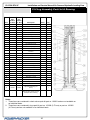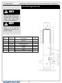
1
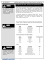
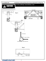
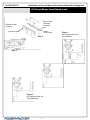
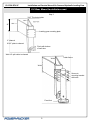
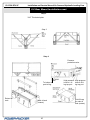
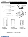
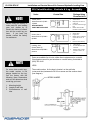
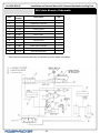
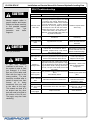
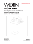
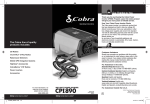
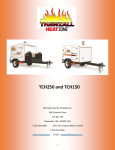
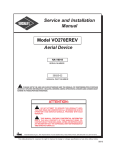
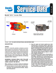
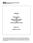
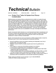
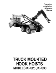
An Actuant Company
Installation and Service Manual
Air Powered Hydraulic Landing Gear
CONTENTS
1.0 Receiving Instructions
2
2.0 Safety Issues
2
3.0 Hydraulic Fluid and Grease
3
4.0 Front Mount installation
4
5.0 Rear Mount Installation
8
6.0 Control Box
11
7.0 Master Valve
13
8.0 Booster Valve
14
9.0 Leveling Valve
15
10.0 Booster Pump Valve
16
11.0 Check Valve
17
12.0 Check Valve Repair
18
13.0 Leg Assembly
20
14.0 Leg Assembly Repair
21
15.0 Stiff Leg
22
16.0 Checking Oil
23
17.0 Preventive Maintenance
24
18.0 Replacement Shoes
26
19.0 Mounting Accessories
27
20.0 Controls and Leg Assembly 28
21.0 System Operation
29
22.0 Auto Booster Control Box
34
23.0 Auto Booster Master Valve 36
24.0 Auto Booster Assembly
37
25.0 Auto Booster Sub-Assembly 38
26.0 Power Valve Assembly
39
27.0 System Operation
40
28.0 Auto Booster Schematic
42
29.0 Troubleshooting
43
30.0 Auto Booster Troubleshooting44
31.0 Warranty
46
Part # 81-1304, REV 0C
Power-Packer
516 Hillcrest Drive
Westfield, WI 53964
PHONE: (800) 745- 4142
FAX: (574) 256-1248
EMAIL: [email protected]
www.powerpackerus.com
© Copyright 2015, Power-Packer. All rights reserved. Issued: April 2015
81-1304 REV 0C
Installation and Service Manual Air Powered Hydraulic Landing Gear
1.0 Important Receiving Instructions
Visually inspect all components for shipping damage prior to
installation. Shipping damage is not covered by warranty. If shipping
damage is found, notify carrier at once. The carrier is responsible for
all repair and replacement costs resulting in damage from shipment.
For most current manual, see http://www.powerpackerus.com
Product descriptions and specifications are subject to change. For
specific versions related to your product, contact us.
2.0 Safety Issues
Read all instructions, warnings and cautions carefully. Follow all
safety precautions to avoid personal injury or property damage during
system operation. Power-Packer cannot be responsible for damage
or injury resulting from unsafe product use, lack of maintenance or
incorrect product and/or system operation. Do not remove warning
labels, tags or decals. Contact Power-Packer when in doubt as to the
safety precautions and operations.
This manual follows a system of safety alert symbols, signal words
and safety messages to warn the user of specific hazards. Failure to
comply with these warnings could result in serious personal injury or
death, as well as damage to equipment or other property.
This is a Safety Alert Symbol that appears throughout this manual. It
is used to alert you to potential physical injury hazards. Pay close
attention to Safety Alert Symbols and obey all safety messages that
follow this symbol to avoid possible serious personal injury or death.
WARNING
CAUTION
NOTE
Safety Alert Symbols are used in conjunction with certain Signal
Words that call attention to safety messages or property damage
messages and designate a degree or level of hazard seriousness.
The Signal Words used in this manual are WARNING, CAUTION,
and NOTICE.
WARNING indicates a hazardous situation that, if not avoided, could
result in death or serious injury.
CAUTION indicates a hazardous situation that, if not avoided, could
result in minor or moderate injury.
NOTE indicates information considered important, but not hazardrelated (e.g. messages related to property damage.)
2
81-1304 REV 0C
NOTENOTE
Our experience indicates
that mixtures of oil and fuel
oil cause seals to swell,
resulting in subsequent
sticking or sluggish action
on the landing legs.
Installation and Service Manual Air Powered Hydraulic Landing Gear
3.0 Hydraulic Fluid and Grease Specifications
Power-Packer recommends using a quality ISO 15 anti-wear hydraulic
fluid for most applications. If operating in cold temperatures slower
operation will occur. If slower operation in cold weather affects your
operations, we recommend using a fluid specially-formulated for cold
temperatures. We have found that ISO 15 anti-wear hydraulic fluids
work well with Power-Packer systems to -20° F.
If consistently operating at temperatures below -20°F, then we
recommend hydraulic fluids conforming to MIL-PRF-5606H or MIL-H5606A (obsolete). If you have any questions regarding fluid
recommendations, please call us.
NOTE
Always grease leg in the
fully retracted position.
DANGER
Do not place any body parts
(feet) below leg shoe while
in operation. The operator
must be fully aware of
people’s position in the
trailer area.
3
81-1304 REV 0C
CAUTION
Do not weld on truck frame.
Installation and Service Manual Air Powered Hydraulic Landing Gear
4.0 Front Mount Installation
Step 1Remove manually-operated landing gear (if applicable).
Step 2- Leg Mounting
Install landing gear legs to standard landing gear mounting brace. Allow
12" ground clearance with legs fully retracted. Use 5/8"- 18 UNF grade
5 hex head cap screws and hex nuts. Torque to 100 ft-lbs.
Step 3 - Bracing
Brace leg as shown. Any bracing system must brace the bottom of the
landing gear leg to structural members of the trailer in two directions 90°
apart. Make sure bracing will not interfere with tractor. Use proper size
(5/8") or bigger, grade 5 or better.
NOTE
Split collar to be located
flush with bottom of well
tube. Locate grease fitting
in slot.
NOTE
Install spacers between slit
collars (4).
Do not weld bracing and/or ears directly to well tube. Weld to split collar
only. Do not weld split collar to leg. Install spacers between split
collars. Do not use split collar bolts to attach bracing. Split collar bolts
should be torqued to 20 ft-lbs. Do not weld on collar while on leg.
Step 4 - Control Box Mounting
Determine desired control box location. No part of control box or
handles should extend beyond the sides of the trailer. A 10- and 12-foot
high pressure hose, and 25 feet of low-pressure tubing are supplied
as standard. If other lengths are needed, please call Power-Packer.
Hold control box in desired location. Be sure trailer cross members are
free of rust and undercoating where control box hanger straps make
contact. Tack weld hanger straps in place. Remove hanger strap bolts
and lower control box. Finish welding hanger straps to trailer cross
members and remount control box. Torque mounting bolts to 20 ft-lbs.
Step 5 - Plumbing
Cut emergency brake line and insert tee and 75 PSI pressure
protection valve (part number 86640 PPV Kit). Pressurized air is
required to positively hold the legs up when the travel is traveling, and
to operate the legs when the trailer is parked. Then usual source of air
is the tractor’s compressor via the air supply line.
Figure 1 (page 7) is a circuit with a third gladhand that meets the
above requirements. To operate landing gear, the operator moves the
tractor’s supply gladhand from the trailer’s supply line connection to the
3rd gladhand (4). This sets the trailer’s parking brakes and connects
tractor air to landing gear’s control box. The pressure protection valve’s
integral check valve prevents loss of air.
4
81-1304 REV 0C
CAUTION
Installation and Service Manual Air Powered Hydraulic Landing Gear
4.0 Front Mount Installation cont.
Do not weld on truck frame.
Step 2
Cross Brace
Rear of Trailer
Grease fitting in split collar slot
Step 4
5
81-1304 REV 0C
Installation and Service Manual Air Powered Hydraulic Landing Gear
4.0 Front Mount Installation cont.
NOTE
The parking brakes of the
tractor and/or trailer will not
function with this circuit
because the supply line is
not vented when landing
gear
functions.
An
alternative
method
of
applying the parking brakes
should be provided. The
3rd gladhand circuit does not
cause the parking brakes to
be inoperative when the
landing gear is operating.
NOTE
Figure 1 Item Descriptions:
1) Tee connector 3/8 NPT
2) Pressure
protection
valve 3/8 NPT 50-55
PSI and integral check
valve
3) Check valve soft seal
In final preparation to move the trailer, the operator returns the tractor's
supply gladhand to the trailer's supply line connection. This returns the
truck's air system to normal while providing air via the tee (1) and
pressure protection valve (2) to positively hold the legs up. Check valve
(3) prevents loss of air through the 3rd gladhand. Figure 2 (page 7) is a
circuit showing a hook-up without addition of the 3rd gladhand. While
the needs of landing gear are satisfied, the trailer's parking brakes will
not be set until landing gear's operation is complete and the supply line
is vented. If this type of hook-up is desired, an alternate method of
applying the parking brakes while landing gear is operational should be
provided.
Connect 1/2" 0.0. nylon tubing from the bottom port of each leg to a
union tee midway between each leg. Connect 1 /2" 0.D. nylon tubing
from third connection of tee t o bottom port of retract oil!
tank (step 4).
Check to insure shunt valves are installed per item 14 on page 5.
Connect 3/8" H.P. hose from top port of right (curb) side leg to HYD.
R.H. leg port to manifold. Connect 3/8" H. P. hose from top port of leg
(road) side leg to HYD. L.H. leg port on manifold.
Step 6 - Filling
Connect air to trailer (50 PSI maximum) and move master valve handle
to "up travel." When legs are fully retracted and air is no longer heard
moving, remove fill cap from main oil tank extend fill tube. Fill main oil
tank extend with 11 quarts of fluid. (See page 3
for fluid
recommendations.) Replace fill cap.
Extend legs to ground. (Refer to front decal for operating instructions.)
Fully retract legs. This procedure bleeds air from the extend side of the
leg.
4) Gladhand
NOTE
Figure 2 Item Descriptions:
1) Tee connector 3/8 NPT
Extend legs to ground and cycle booster valve until legs are fully
extended. Keep master valve in ”down park” position. When air is no
longer heard moving, remove retract oil tank fill plug. Fill retract oil tank
with 6 quarts of fluid. Replace fill plug. Fully retract legs.
Additional operation by fully extending and retracting the legs may be
required to bleed all air form the system (2 cycles minimum). Check all
fittings and hoses for leaks. Secure hoses in a manner that will not
cause chafing. Your system is now ready for use.
2) Pressure
protection
valve 3/8 NPT 50-55
PSI and integral check
valve
6
81-1304 REV 0C
Installation and Service Manual Air Powered Hydraulic Landing Gear
4.0 Front Mount Installation cont.
Main oil tank
(extend),
11 quarts
Retract oil tank
6 quarts
Fluid level port
Fluid fill cap
Step 4
Step 5
Figure 2
Air Pressure Hook-Up
Two Gladhands
7
Figure 1
Air Pressure Hook-Up
3rd Gladhand
81-1304 REV 0C
Installation and Service Manual Air Powered Hydraulic Landing Gear
5.0 Rear Mount Installation
Step 1
Determine location for landing gear legs. Normally, legs will be
mounted between the rear tires. You should allow 6 inches of ground
clearance (4 inches absolute minimum). Remember to allow for spring
deflection when trailer is loaded.
Step 2 - Leg Mounting
This is one common way of mounting "rear mount" landing gear. Other
methods may be used. When designing a mounting structure, provide
enough strength to lift the trailer and proper bracing to take any side
loading.
Remove wheels, if necessary. Cut a 6-inch channel to desired length
(varies with trailer frame and leg stroke).
Weld a 12-inch long piece of 3/16" steel plate to the inside of the
channel. These plates should be wide enough to place the center of the
leg between the tires when the leg is mounted to the channel.
Weld a loose mounting plate (order from Power-Packer) to the channel
at the proper height (per installation requirements).
Weld a split collar half to the mounting channel where the bottom of the
well tube will be located. Weld this fabrication to the trailer frame.
Fabricate second leg mounting structure in the same manner.
Mount legs using 5/8"-18 UNF grade 5 bolts. Torque to 100 ft-lbs.
Clamp remaining split collar halves in place with 1/2"-20 UNF grade 5
bolts. Torque to 20 ft-lbs.
Step 3 - Bracing
Other bracing systems may be used to suit the application. The bottom
of each leg must be braced to the trailer frame members in two
directions 90° apart. These braces should not be welded to the leg.
They may be mounted to the split collar, channel, and/ or the cross
brace near the leg. See page 5, steps 2 and 3 for clearer view of split
collars.
Weld cross brace from bottom of one channel to the other.
Weld a brace from the bottom of each channel to the trailer frame at 45°
angle. This brace should be pointed directly away from the
leg. On each side, weld bracing pointed straight forward and/or back
ward at a 45° angle from each channel on the cross brace to the trailer
frame.
Step 4 - Control Box Mounting
Please see Steps 4, 5 and 6 starting on Page 7 for control box
mounting, plumbing and filling.
8
81-1304 REV 0C
Installation and Service Manual Air Powered Hydraulic Landing Gear
5.0 Rear Mount Installation cont.
Step 2
3/16” Thick steel plate
12”
Landing gear mounting plate
6” channel
9”x12” plate to channel
Flush with bottom
of well tube
Weld 1/2 split collar to channel
Weld
Trailer frame
Weld
Secure to
mounting bracket
with bolts
Fixed foot
9
81-1304 REV 0C
Installation and Service Manual Air Powered Hydraulic Landing Gear
5.0 Rear Mount Installation cont.
Step 2
3/16” Thick steel plate
Step 3
Step 4
Pressure
protection valve
To bottom
port left leg
Retract oil
tank
Main oil tank
(extend)
10
High pressure High pressure
hose to L.H. hose to R.H.
leg top port
leg top port
Fluid fill cap
for main oil
tank (extend)
81-1304 REV 0C
Installation and Service Manual Air Powered Hydraulic Landing Gear
6.0 Control Box Drawing
11
81-1304 REV 0C
Installation and Service Manual Air Powered Hydraulic Landing Gear
6.0 Control Box Parts List
Item
1-18
Part Number
Description
Qty
100104
100106
Control box - standard
1
Control box - high pressure
1
1
100316
Base channel
2
2
100322
Hanger strap
2
3
100317
Base plate
1
4
100120
Leveling valve
1
5
100117
Master valve
1
6
100122
Booster valve
1
7
100327
Handle
3
7A
18-1002
Roll Pin
3
100124
Booster pump-standard
1
100126
Booster pump-high pressure
Steel line (master valve to
leveling valve)
Steel line (manifold to leveling
valve) right leg
Steel line (manifold to leveling
valve) left leg
Steel line (master valve to
booster pump)
Manifold
1
8
9
100320
10
100191
11
100190
12
100318
13
100129
14
Shunt valve*
1
1
1
1
1
2
as
req'd
15
001-Bulk
Nylon tubing (typ)
16
100128
Main oil tank (extend)
1
17
100127
Retract oil tank
1
18
100321
Cover
1
19
100326
Decal
For control box part no. 100104
use 1004-043 shunt valve
For control box part no. 100106
use 1004-038 shunt valve
1
*
12
81-1304 REV 0C
Installation and Service Manual Air Powered Hydraulic Landing Gear
7.0 Master Valve Part List & Drawing
Item
1
Part
Number
2
*
100135
3
07-1024
4
07-1012
5
100329
Description
Qty
Wiper
1
Oil Return Block
1
Branch T (3/8 npt x 08.37° flare)
90° elbow (3/8 npt x ½ comp.)
1
1
2
3
6
15-1004
Mounting bracket
Hex head cap screw (3/8-16x3/4 lg)
7
16-1002
Lock Washer (3/8)
2
8
100134
Front adapter plate
1
9
15-1002
2
10
11
*
100328
Socket head cap screw (1/4-28 x 5/8 lg.)
O-ring (3/4 i.d. x 1/8 c.s
Valve spool
1
12
18-1002
Roll pin (5/32 dia. x 1" lg.)
1
13
15-1001
Roll pin (5/32 dia. x 1" lg.)
4
1
2
14
100133
15
15-1003
Rear adapter plate
Hex head cap screw (1/4-20 x 3/4 lg.)
2
16
16-1001
Lock washer (1/4)
2
17
O-ring (7/16 i.d. x 3/32 c.s.)
1
18
*
09-1002
Air valve
1
19
07-1017
07-1016
Connector (3/8 npt x 1/2 comp.)
45° elbow (3/8 npt x 1/2 comp.)
1
20
21
10-1002
Grease fitting
2
22
*
18-1004
Gasket
Roll pin (1/4 dia x 1 ½” lg.)
1
23
24
18-1011
Roll pin (1/4 dia x 1” lg.)
2
25
001-Bulk
Vent tube
1
*
Contained in valve repair kit 100224
13
1
1
Part Nos. 100117
100313
81-1304 REV 0C
Installation and Service Manual Air Powered Hydraulic Landing Gear
8.0 Booster Valve Part List & Drawing
NOTE
Valve is not repairable.
Purchase a complete valve
assembly.
Part Nos. 100122
100314
Item
Part
Number
Description
Qty
1
100332
Handle adapter
1
2
18-1001
Roll pin (5/32 dia. x 3/4 lg.)
1
3
15-1034
Machine screw (#10-24 x 3/8 lg.)
4
4
100331
Mounting bracket
1
5
09-1001
Air valve
1
6
07-1001
Pipe plug (3/8 npt)
1
7
07-1016
45° elbow (3/8 npt x 1/2 comp.)
1
8
07-1012
90° elbow (3/8 npt x 1/2 comp.)
1
14
81-1304 REV 0C
Installation and Service Manual Air Powered Hydraulic Landing Gear
9.0 Leveling Valve Part List & Drawing
Part No. 100120
Item
Part
Number
Description
Qty
1
15-1014
Socket head cap screw (5/16-18 x 1/21g.)
3
2
100188
Mounting bracket
1
3
15-1004
Hex head cap screw (3/8-16 x 3/41g.)
2
4
07-1010
90° elbow (3/8 npt x 08 37° flare)
2
5
07-1025
90° elbow (3/8 npt x 08 37° flare)
1
6
100298
Valve body
1
7
10-1002
Grease fitting
2
8
18-1003
Roll pin (3/16 dia. x 1" lg.)
2
9
*
O-ring (3/4 i.d. x 1/8 c.s.)
10
100336
Valve spool
11
100301
Return spring
12
100300
Spring Collar
13
18-1004
Roll pin {1/4 dia. x 1-1/2 lg.)
*
Contained in valve repair kit 100224
15
4
1
1
1
1
81-1304 REV 0C
Installation and Service Manual Air Powered Hydraulic Landing Gear
10.0 Booster Pump Valve Part List & Drawing
Part No. 100124 Standard
100126 High Pressure
Item
Part
Number
Description
Qty
1
07-1011
45° elbow (3/8 npt x 1/2 flareless)
1
2
19-1001
Steel ball (1/2 dia., grade 100)
2
3
100171
Booster output port
1
100166
Std. booster nozzle
1
4
100183
High pressure booster nozzle
1
5
15-1005
Hex nut (5/16-24)
8
6
16-1003
Lock washer (5/16)
8
7
100170
Tie rod
4
8
9
10
11
12
*
O-ring standard (1" i.d. x 1/8 c.s.)
1
*
O-ring- high pressure (7/8" i.d. x 1/8 c.s.)
1
*
Back-up washer- standard (1" i.d. x 1/8 c.s.)
1
*
Back-up washer- high pressure (7/8" i.d. x 1/8 c.s.)
1
100160
Standard stop tube
1
100182
High pressure stop tube
1
100165
Booster tube
1
100161
Standard piston rod assembly (1" rod)
1
100180
High pressure piston rod assembly (7/8" rod)
1
13
*
High pressure piston rod assembly (7/8" rod)
1
14
*
Back-up washer (5" i.d. x 3/16 c.s.)
1
15
100159
Blind end cap
1
16
07-1012
90° elbow (3/8 npt x 1/2 comp.)
1
*
Contained in repair kit 100408
16
81-1304 REV 0C
Installation and Service Manual Air Powered Hydraulic Landing Gear
11.0 Check Valve Part List & Drawing
Part No. 100540
Item
Part
Number
Description
Qty
Check valve assembly
1
1
100540
100534
Check valve body
1
2
100209
Check valve cap
1
3
100208
Piston spring
1
4
15-1011
Hex head cap screw
6
5
100535
Check valve piston
1
6
*
O-ring
1
7
*
O-ring
1
8
*
Quad ring
1
1-15
9
*
Steel ball
1
10
*
O-ring
1
11
*
Check insert
1
12
*
Spring
1
13
100531
Check body insert
1
14
100533
Check insert top
1
15
*
O-ring
1
These items contained in check
valve repair kit 100221
1
*
(8)
(1)
(15)
17
(1)
(3) (7)
(5)
81-1304 REV 0C
NOTCAUTION
Use eye protection.
Installation and Service Manual Air Powered Hydraulic Landing Gear
12.0 Check Valve Repair Procedure
Use Repair Kit Part No. 100221
The item numbers listed below are the same as those listed on the
check valve assembly drawing, page 17.
IMPORTANT:
CAUTION
Check valve cap and check
valve piston are spring
loaded.
1. Inspect all parts for scratches, nicks and other defects, replace if
necessary.
2. All new seals and parts should be lightly coated with grease (grade
0 or 00) before reassembling.
3. Remove rust and other debris using a very fine steel wool if
required. Do not use emery cloth because it leaves scratches in
metal parts that causes excessive wear on o-ring and parts.
4. Remove check valve assembly, Part No. 100540 from leg by
using strap wrench in a ccw manner. To do this without removing
leg from trailer requires a 2" clearance above the check valve.
Make sure all pressure is relieved before check valve is removed.
5. Thoroughly clean all hard parts before assembly.
DISASSEMBLY:
A. To remove check valve from leg, make sure no weight is being
supported by legs. Have legs slightly extended from full retract
position to relieve any internal pressure in legs. Disconnect the
hoses from the leg. You may wish to mark which hose goes to what
port. Unscrew the check valve from the leg using counter clockwise
rotation.
B. Remove the six H.H.C.S., Item 4 and check valve cap, Item 2.
Normally check valve piston, Item 5 and piston ring, Item 3 will
release at this point. Remove o-rings, Items 6, 7,and 8. If check
valve piston, Item 5 and piston spring, Item 3, do not release,
proceed with C and D below and perform E below.
CAUTION
Check valve parts are
spring loaded.
C. Turn check valve body, Item 1, upside down. Check insert body,
Item 13 is installed and held in by an interference fit. To remove
slide a 5/8” deep socket onto check insert body, Item 13 and using
a socket cheater bar in rigid position, work back and forth until
check insert body is released.
D. Remove o-ring, Item 15 and check insert top, item 14. Remove
steel ball, Item 9, o-ring Item 10, check insert, Item 11 and
spring, Item 12 form check insert body, item 13.
E. If check valve piston, Item 5 has not released, lay check valve
body, Item 1, on side and insert brass or aluminum drift punch form
bottom side of check valve body and tap with light hammer.
18
81-1304 REV 0C
NOTCAUTION
Installation and Service Manual Air Powered Hydraulic Landing Gear
12.0 Check Valve Repair Procedure cont.
ASSEMBLY:
Use eye protection.
1. Place insert check top, Item 14 into counter bore flat side down.
Place o-ring, Item 15 into shallow counter bore.
CAUTION
Check valve cap and check
valve piston are spring
loaded.
2. Assemble check insert body, Item 13 by placing check insert,
Item 11, in seat flat side down into check insert body, Item 13.
Insert spring, Item 12, insert steel ball, Item 9, insert Teflon oring, Item 10 and press firmly into place.
3. Place check insert body, Item 13, into check valve body, Item 1,
counter bore and use a large punch and light hammer to drive the
check insert body, Item 13, into place. Interference fit.
4. Turn check valve assembly, 100540, right side up. Install quad
ring, Item 8. Install o-ring, Item 6 on check valve piston, Item 5.
Install piston spring, Item 3 on check valve piston, Item 5 and
insert in piston cavity where Item 5 is located. Install o-ring, Item 7
in groove. Place check valve cap, Item 2 over check valve
piston, Item 5 and compress to install H.H.C.S., Item 4 and torque
to 9 ft.-lbs.
5. Reinstall on leg making sure that o-ring and backup washer are on
piston rod and tighten check valve assembly, 100540 with strap
wrench. The check valve may have to be rotated to connect the
hoses. To do this, remove H.H.C.S., Item 8 (see leg assembly
drawing page 20) and rotate check valve, clockwise only, so ports
are accessible then reinstall H.H.C.S., Item 8. Connect hoses and
cycle legs several items to bleed air from system, then check the oil
level.
19
81-1304 REV 0C
Installation and Service Manual Air Powered Hydraulic Landing Gear
13.0 Leg Assembly Part List & Drawing
Item
1
Part
Part
Number Number
3.5" Bore 4.0" Bore
100540
100540
Description
Notes
Check valve assembly
Qty
1
2
O-ring
1, 2
1
3
Back-up washer
1, 2
2
4
O-ring
1, 2
1
5
Back- up washer
1, 2
1
6
Snap ring, 2" rod
2
1
7
O-ring
2
1
8
15-1004
15-1021
Hex head cap screw
1
9
16-1002
16-1002
3/8" lock washer
4
10
15-1012
15-1012
Hex head cap screw
1
11
100278
100279
Cylinder head retainer
1
12
Retaining ring
2
1
13
Oil seal
2
1
1
14
Rod seal
2
15
O-ring
2
1
16
Back-up washer
2
1
17
100216
100276
Cylinder head
1
18
*
*
Piston rod
1
19
*
*
Well tube
20
21
Wear ring
10-1001
10-1001
1
2
2
Grease fitting
1
22
Piston seal
2
1
23
O-ring/square seal
2
1
24
Back-up washer
2
2
25
Wear ring
2
1
Snap ring, 1.75 rod
1
27
100217
*
Piston
1
28
*
*
Cylinder tube
26
29
1
Nylon ball
2
1
30
Set screw
2
1
31
Split collar assembly (not
shown)
100346
*
100348
1
State the part number and part
description when ordering.
Notes:
1. These items are contained in check valve repair kit part no. 100221 and are not available on
an individual basis.
2. These items are contained in leg repair kit part no. 101086 (3.5” bore) or part no. 100422
(4.0” bore) and are not available on an individual basis.
20
81-1304 REV 0C
NOTE
When disassembling and
reassembling the leg, care
should be taken to keep all
parts clean and to prevent
parts from being damaged.
CAUTION
While lifting piston rod, oil
will squirt out of side port at
top of rod.
NOTE
All seals should be coated
lightly with grease before
installation into leg.
Installation and Service Manual Air Powered Hydraulic Landing Gear
14.0 Leg Assembly Repair Procedure
3.5” Bore Leg Repair Kit Part No. 101086
4.0” Bore Leg Repair Kit Part No. 100422
DISASSEMBLY/ASSEMBLY
The item numbers listed below are the same as those listed on the leg
assembly drawing.
1. To remove leg from trailer, make sure no weight is being supported
by legs. Have legs slightly extended from full retract position to
relieve any internal pressure in legs. Disconnect the hoses from the
leg. You may wish to mark which hose goes to what port. Remove
the leg from the trailer.
2. Remove the lock valve, Item 1 from the leg by screwing counter
clockwise. (If you need only to repair the lock valve, it may be
removed from leg while still on trailer if you have a minimum of 2"
clearance above.)
3. Remove o-rings and back-up washers, Items 2, 3, 4 and 5. Using
a snap ring pliers, remove snap ring, Item 6. Loosen hex screw,
Item 8.
4. Lift well tube, Item 19 off lower leg assembly. Lift piston rod,
Item 18 to gain access to top of cylinder head, Item 17.
5. Remove 4 hex screws, Item 10. Lift cylinder head retainer, Item
11. A wire or rubber band maybe used to hold Item 11 to sprocket
near the top of the piston rod (out of the way).
6. Using a flat screwdriver, carefully remove spiral retaining ring,
Item 12. Lift rod piston assembly out of cylinder tube, item 28.
7. Using a large snap ring pliers, remove heavy duty snap ring Item
26 or remove the set screw, Item 30. Remove the piston, Item 27,
cylinder head, Item 17, retaining ring, Item 12 and cylinder head
retainer, Item 11.
8. Remove all seals and wear rings. Clean all parts. Inspect all bearing
surfaces tor scratches, nicks or other defects; replace if necessary.
Replace all wear rings and lightly lubricate all seals before installing
on legs.
9. Carefully reassemble the leg in reverse order as described above.
Where applicable, torque piston, Item 27 to 40-50 ft-lbs. Apply 2
drops of Loctite 277 or equivalent to set screw, Item 30 and torque
to 50 in./lbs.
10. Return leg to trailer and reconnect all hoses. Apply grease to
grease fittings, Item 21 and cycle legs fully several times to bleed
air from the system. Check oil level as described in maintenance
section of manual.
21
81-1304 REV 0C
Installation and Service Manual Air Powered Hydraulic Landing Gear
15.0 Stiff Legs Part List
NOTE
When ordering parts for a
stiff leg model, all parts are
common with a non-stiff leg
model (see page 20),
except for the parts below.
NOTE
Items 3, 4, 5 can be
purchased in Hitch pin kit
part no. 101504.
Item
1
Part
Number
Description
Qty
1
2
*
*
Well tube
Stiff leg
1
3
18-1019
Cotterless hitch pin
1
4
99-1002
Ferrule
2
5
15-1052
Screw
1
6
087-009000
Cable
1
*
State the part number when ordering.
22
81-1304 REV 0C
Installation and Service Manual Air Powered Hydraulic Landing Gear
16.0 Checking Oil
NOTE
Correct oil levels in both
tanks on landing gear is
very important.
CHECKING OIL LEVELS
Procedure for checking and filling both oil tanks:
1. Main Oil Tank. Tank is located behind controls on control box. Fill
tube to left side of control box.
a. Move master valve handle to "up travel" right.
b. When legs are fully retracted and air is no longer heard
moving, remove fill tube cap.
c. Fill main oil tank until additional oil will not be accepted.
d. When legs are fully retracted and air is no longer heard
moving, remove fill tube cap.
e. Fill main oil tank until additional oil will not be accepted
2. Retract Oil Tank. Tank is located to left of control box.
a. Move master valve to "down park" left and extend both legs
to ground. Cycle booster valve (right side of control box)
manually or hold auto booster button in (on auto booster
system) until both legs are fully extended.
b. When air is no longer heard moving, remove retract oil side
tank fill plug and fill until additional oil will not be accepted.
Replace fill plug.
c. Move master valve to "up travel" and fully retract both legs.
d. Cycle system 2 complete cycles to insure all air is
removed from system.
CAUTION
Check valve parts are
spring loaded.
23
81-1304 REV 0C
Installation and Service Manual Air Powered Hydraulic Landing Gear
17.0 Preventive Maintenance
NOTE
In
order
to
obtain
continued high performance
from your landing gear
unit,
we
recommend
following the yearly service
procedure.
NOTE
NLGI grade "00" or "0"
lithium grease, use hand
grease gun only.
In order to obtain continued high performance from your landing
gear unit, we recommend the following yearly service procedure:
1. Change Oil
a. With legs fully extended and master valve in "down park,"
drain retract oil tank by removing nylon line at bottom of
tank or plug if equipped. Reconnect and refill with 6 quarts
of approved fluid to fill port level.
b. Connect air supply to system and fully retract legs (leave
handle in "up travel").
c. Disconnect air supply from system.
d. Disconnect top hydraulic line at each leg and put ends into
container to catch oil.
e. Connect air supply to system.
f. Very slowly, move master valve handle toward "down park"
position until oil starts coming out of lines. Leave in this
position until all oil has been exhausted from main tank.
g. Move master valve handle to "up travel" position and reconnect lines to leg.
h. Remove filler cap from end of fill pipe of main oil tank and
fill with 11 quarts of approved fluid.
i. Operate landing gear for at least two full cycles (complete
leg strokes) to bleed air from system.
2. Check all hydraulic lines and fittings for leaks
spots. Replace any defective lines and fittings.
and worn
3. Check tor loose bolts and nuts.
LUBRICATION OF LANDING GEAR SYSTEMS
In order to provide continued performance of your landing gear
system, the following lubrication procedures are required at
approximately six month intervals:
Spray WD-40 or equivalent
into booster pump vent
hole.
Inject anti-seize to all 4 grease
fittings (LOCTITE or "FELPRO"
CS-A). If unavailable, use NLGI
grade "00" or "0" lithium grease.
24
81-1304 REV 0C
Installation and Service Manual Air Powered Hydraulic Landing Gear
17.0 Preventive Maintenance cont.
NOTE
In
order
to
obtain
continued high performance
from your landing gear
unit,
we
recommend
following the yearly service
procedure.
LUBRICATION OF LANDING GEAR SYSTEMS cont.
Inject grease into vent hole (on front of new soft seat check valve)
(Figure 1) and on the rear of older hard seat check valve (Figure 2)
using a rubber tip adapter ("Lubrimatic" code 11860). Check valves
produced after July 1987 have a grease fitting without a ball.
When all lubrication is completed, extend and retract legs full stroke.
Excess grease will be pushed out of leg check valve vent.
Figure 1
NOTE
Inject grease into vent hole or grease fitting
(use hand grease gun only).
Fully extend leg and wipe
old grease off cylinder tube.
Retract leg and as leg is
retracting apply grease to
grease fittings at bottom of
well tube.
Inject grease after cleaning cylinder tube. See
note (power grease guns may be used at this
point).
Figure 2
Inject grease into vent hole or grease fitting
(use hand grease gun only).
25
81-1304 REV 0C
Installation and Service Manual Air Powered Hydraulic Landing Gear
18.0 Replacement Shoes
Part No. 100411
For the convenience of Power-Packer customers, the replacement foot,
or shoe, has been redesigned to facilitate an easier repair and
replacement of damaged or worn feet. The new design should make
changing feet simpler and less time-consuming. The following steps
illustrate the procedure.
1. Replacement Foot part number 100411.
2. Retract leg.
3. Remove damaged foot. Be sure not to cut into end cap of cylinder.
There are two notches 180° apart on the end cap on the cylinder
tube. Use these notches to start your cut.
4. Place shoe halves under leg.
5. Lower leg to shoe halves, shoe will self center, weld across the top.
6. Retract leg and weld across the bottom.
1. Replacement Foot
part number 100411
4. Place shoe halves
under leg.
26
2. Retract leg.
5. Lower leg to shoe
halves, shoe will self
center, weld across
the top.
3. Remove damaged
foot. Be sure not to cut
into end cap of cylinder
6. Retract leg and
weld across the
bottom.
81-1304 REV 0C
Installation and Service Manual Air Powered Hydraulic Landing Gear
19.0 Mounting Accessories
Part No. 100354
Curved ear
Part No. 100357
Straight ear
Part No. 100353
Angle ear
Part No. 100346
Split collar assembly (100 series)
Part No. 100348
Split collar assembly (400 series)
Part No. 100226
Mounting plate
9 x 16 x 3/8, 14 holes
(400 series)
Part No. 100509
Mounting plate
9 x 10⁻⁵/8 x 1/4, 10 holes
(100 series)
Part No. 100502
Mounting plate
9 x 8-3/8 x 1/4, 8 holes
(100 series)
Note: All holes 11/16” dia. On 7-1/2” x 2-1/4” centers
27
81-1304 REV 0C
Installation and Service Manual Air Powered Hydraulic Landing Gear
20.0 Identification - Controls & Leg Assembly
NOTE
Before calling the factory to
order parts for your landing
gear unit, please try to
identify the series of control
box and the model leg you
have.
If you have any
doubts, contact the factory
for assistance.
Series
Control Box
Power Gear I
Manufactured 1/1965 –
3/1980
DISCONTINUED
PARTS NOT AVAILABLE
Power Gear II
Manufactured 3/1980 –
8/1980
Distinguishing
Characteristics
1.
2.
3.
4.
1.
2.
3.
4.
Landing Gear
(Power Gear III)
Manufactured 8/1980 –
present
NOTE
On some older model legs,
the model number is not
always located on the leg.
Call the factory with the
following three dimensions
and we will determine what
model leg you have:
1.
2.
3.
Yellow decal.
May/may not have air
side tank.
Fill tube comes through
box.
Master valve handle
located in center of box.
White decal.
Larger box.
Master valve located in
upper left corner of
box.
Please contact factory.
Yellow decal.
Fill tube between box
and tank.
Master valve Handle
located in center of
box.
Parts are available for all units, either direct replacement or a retrofit.
Check parts manual for part numbers or consult factory for details at
(800) 745-4142.
LEGS
The model number for the legs is located on the well tube
(outermost tube) between the 9/16 hex screw and the caution decal
(see diagram).
1. Mounting height
2. Length of well tube
3. Circumference of well
tube
28
81-1304 REV 0C
Installation and Service Manual Air Powered Hydraulic Landing Gear
21.0 System Operation – Standard
CONTROL BOX HYDRAULIC CIRCUIT OPERATION
.
The Landing Gear Control Box is an air powered hydraulic power supply
designed to operate two Landing Gear Legs. The Control Box will
supply high pressure hydraulic energy to extend the legs or lift the trailer
and low pressure hydraulic to retract the legs. For best results, lock
engine throttle at 1000-1200 ppm.
The Control Box has six (6) major components. They are:
1. Master Control Valve - The Master Control Valve has two parts,
the rear or air portion and the front or oil return block. The Master
Valve is used to extend or retract the legs.
2. Leveling Valve - The Leveling Valve is used to adjust for uneven
ground or load conditions and slows down or stops one leg or the
other.
3. Booster Valve - The Booster Valve is used to cycle the Booster
Pump.
4. Booster Pump - The Booster Pump is the energy "transformer'‘
that changes low pressure air energy into high pressure hydraulic
energy to extend the legs.
5. Main Oil Tank - The Main Oil Tank is used to store and pressurize
the oil used to extend the legs.
6. Retract Oil Tank -The Retract Oil Tank is used to store and
pressurize the oil used to retract the legs.
CIRCUIT OPERATION
To best explain circuit operation, first assume that both legs are at midstroke. Turning the Master Control Valve as far counter clockwise as it
will go will put the Master Valve in the "legs retract" mode.
In this position any air pressure in the Main Oil Tank is vented to
atmosphere through the air portion of the Master Valve.
Air Pressure from the emergency air brake line is connected to the
Retract Oil Tank by the air portion of the Master Valve.
At the Retract Tank the air pressure forces oil out to the bottom or
retract port of the legs, causing the legs to retract.
Oil returning from the top port or extended side of the legs comes in
through the Leveling Valve. By turning the Leveling Valve handle one
way or the other either leg may be partly or completely stopped.
Oil flows out of the Leveling Valve and to the Booster Valve and to the
Oil Return Block in the Master Valve. At the Booster Pump the oil is
stopped from flowing by one of the ball checks in the Booster Nozzle but
the oil can flow in the Master Valve and return to the Main Oil Tank.
By moving the Mater Valve handle SLIGHTLY clockwise, it is possible o
slow the legs down as they retract.
When the legs are fully retracted, the air pressure in the Retract Tank
will hold the legs up. The Master Valve should always be in the position
for over-the-road travel.
To extend the legs, rotate the Master Valve handle clockwise as far as it
will go. Air pressure inside the Retract Oil Tank is vented to
atmosphere through the air portion of the Master Valve.
29
81-1304 REV 0C
Installation and Service Manual Air Powered Hydraulic Landing Gear
21.0 System Operation – Standard cont.
CIRCUIT OPERATION cont.
.
Air pressure from the emergency air brake line is connected to the
Booster Valve and also to the Main Oil Tank. The oil return passage in
the Master Valve is blocked with the Master Valve and also to the Main
Oil Tank.
The oil return passage in the Master Valve is blocked with the Master
Valve in the legs extended position, and oil cannot flow through it.
The legs extend in two "phases." In the first phase, the legs travel
rapidly to the ground. After they are firmly on the ground, the Booster
Pump must be actuated to lift the load. This is phase two.
In the first phase, "LEGS EXTENDED, RAPID TO GROUND," oil flows
from the main Oil Tank to the Booster Nozzle. The Booster Nozzle has
two ball checks. The bottom check allows oil to flow into the Booster but
not out. The top ball check allows oil to flow out but not in. This
combination allows oil to flow through the Booster Nozzle, to the
Leveling Valve and to the legs.
The Leveling Valve handle may be turned one way or the other to slow
down or completely stop either leg.
Oil from the "RETRACT' side of the leg returns to the Retract Oil Tank
as the legs extend.
Once the legs reach the ground, air pressure alone is not enough to lift
the trailer. In order to lift the trailer, the Booster Valve must be cycled.
This is done by rotating the Booster Valve handle, alternating to both
extremes, all the way clockwise, then counter clockwise, clockwise,
counterclockwise, etc. This is repeated until the trailer has been raised
to the desired height.
As the Booster Valve handle is rotated, this is what happens: When the
handle is rotated clockwise, the blind or back end of the Booster is
vented to the atmosphere. Oil, under air pressure, from the Main Tank
enters the Booster Nozzle and pushes the piston rod back. The top ball
check in the nozzle keeps oil in the legs from "backing up" into the
nozzle.
When the handle is rotated counterclockwise, air pressure is applied to
the large area of the Booster Piston. This large volume of low pressure
air forces the piston and rod assembly forward, into the nozzle, through
the Leveling Valve and to the legs.
This cycle may be repeated as many times as needed to raise the trailer
to the desired height.
To lower the trailer or to retract the legs, slowly move the Master Valve
handle counterclockwise as far as it will go.
30
81-1304 REV 0C
Installation and Service Manual Air Powered Hydraulic Landing Gear
21.0 System Operation – Diagram
.
31
81-1304 REV 0C
Installation and Service Manual Air Powered Hydraulic Landing Gear
21.0 System Operation – Diagram cont.
.
32
81-1304 REV 0C
Installation and Service Manual Air Powered Hydraulic Landing Gear
21.0 System Operation – Diagram cont.
.
33
81-1304 REV 0C
Installation and Service Manual Air Powered Hydraulic Landing Gear
22.0 Auto Booster Control Box – External
Part No. 101676
Item
Part Number
Description
Qty
1
100316
Base channel
2
2
100317
Base plate
1
3
09-1057
Power valve button
1
4
09-1030
Air valve button
1
5
100327
Handle and pin kit
2
6
101522
Front decal
1
7
101518
Bottom cover
1
8
100321
Side cover
1
9
100322
Hanger strip
2
34
81-1304 REV 0C
Installation and Service Manual Air Powered Hydraulic Landing Gear
22.0 Auto Booster Control Box – Internal
Part No. 101676
Item
Part Number
Description
Qty
1
100127
Retract oil tank
1
2
100190
Steel line
1
3
100120
levelign line
1
4
100191
Steel line
1
5
101583
Master valve
1
6
100320
Steel line
1
7
100318
Steel line
1
8
101680
Auto booster assembly
1
9
101181
Main oil tank
1
10
100129
Manifold
1
11
1004-038
Shunt valve
2
12
001-bulk
Nylon tube (typ.)
as req'd
35
81-1304 REV 0C
Installation and Service Manual Air Powered Hydraulic Landing Gear
23.0 Master Valve
Item
1
Part
Number
2
*
100135
3
07-1024
Description
Qty
Wiper
1
Oil Return Block
1
Branch T (3/8 npt x 08.37° flare)
90° elbow (3/8 npt x ½ comp.)
1
4
07-1012
5
100329
15-1004
Mounting bracket
Hex head cap screw (3/8-16x3/4 lg)
1
6
7
16-1002
Lock Washer (3/8)
2
2
2
8
100134
Front adapter plate
1
9
15-1002
2
11
*
100328
Socket head cap screw (1/4-28 x 5/8 lg.)
O-ring (3/4 i.d. x 1/8 c.s
2
10
Valve spool
1
12
18-1022
Roll pin (5/32 dia. x 1" lg.)
1
13
15-1001
Roll pin (5/32 dia. x 1" lg.)
4
14
100133
15
15-1003
Rear adapter plate
Hex head cap screw (1/4-20 x 3/4 lg.)
2
16
16-1001
Lock washer (1/4)
2
17
*
09-1002
O-ring (7/16 i.d. x 3/32 c.s.)
1
18
Air valve
1
19
07-1017
1
1
20
07-1016
Connector (3/8 npt x 1/2 comp.)
45° elbow (3/8 npt x 1/2 comp.)
21
10-1002
Grease fitting
2
*
Gasket
1
22
1
23
24
18-1011
Roll pin (1/4 dia x 1” lg.)
2
25
07-1028
Branch T (3/8 npt x 1/2 comp)
1
*
Contained in valve repair kit 100224
36
Part No. 101583
81-1304 REV 0C
Installation and Service Manual Air Powered Hydraulic Landing Gear
24.0 Auto Booster Assembly
Part No. 101680
Description
Qty
1
Part
Number
101682
Auto booster sub assembly
1
2
101575
Pilot valve assembly
2
3
101681
Power valve assembly
1
4
15-1046
Hex head cap screw
3
5
01-1029
O-ring
1
Item
The following parts are not included in the auto booster assembly and
must be ordered separately.
6
*
Tubing-green, 17"
1
7
8
9
10
*
Tubing-red, 17"
1
*
Tubing-yellow, 14"
1
*
Tubing-black, 12"
1
*
Tubing-red, 7"
1
11
101573
Logic valve assembly
1
12
09-1030
Logic valve button
1
13
07-1237
Clamp
9
*
Order tube kit part no. 101586
37
81-1304 REV 0C
Installation and Service Manual Air Powered Hydraulic Landing Gear
25.0 Auto Booster Sub-Assembly
Part No. 101678
Item
Part
Number
Description
Qty
1
07-1011
45° elbow
1
2
19-1001
Steel ball
2
3
100171
Booster output port
1
4
100914
Booster nozzle
3
5
15-1005
Hex nut
1
6
16-1003
Lock washer
1
7
100907
Tie rod
1
8
*
O-ring
1
9
*
Back-up washer
1
10
100920
Stop tube
1
11
100902
Booster tube
1
12
100918
Piston rod assembly
1
13
*
U-cup
1
14
*
Back-up washer
1
15
100903
Blind end cap
1
*
Order repair kit part no. 100408
Note: Install u cup with lips facing blind end cap.
38
81-1304 REV 0C
Installation and Service Manual Air Powered Hydraulic Landing Gear
26.0 Power Valve Assembly
Part No. 101681
Part
Number
Description
Qty
1
101065
Power valve
1
2
07-1236
Barbed tee
1
3
07-1214
Reducer
1
4
07-1012
Male elbow
1
5
07-1015
Street tee
1
6
07-1114
Male connector
1
7
09-1057
Power valve button
1
8
07-1113
Male swivel elbow
1
9
01-1020
O-ring
1
Item
39
81-1304 REV 0C
Installation and Service Manual Air Powered Hydraulic Landing Gear
27.0 System Operation – Auto Booster
CONTROL BOX HYDRAULIC CIRCUIT OPERATION
.
The Landing Gear Auto Booster Control Box is an air powered hydraulic
power supply designed to operate two Landing Gear Legs. The Control
Box will supply high pressure hydraulic energy to extend the legs or lift
the trailer and low pressure hydraulic to retract the legs. For best
results, lock engine throttle at 1000-1200 ppm.
The Control Box has six (6) major components. They are:
1. Master Control Valve - The Master Control Valve has two parts,
the rear or air portion and the front or oil return block. The Master
Valve is used to extend or retract the legs.
2. Leveling Valve - The Leveling Valve is used to adjust for uneven
ground or load conditions and slows down or stops one leg or the
other.
3. Booster Valve - The Booster Valve is used to cycle the Booster
Pump. It cycles automatically with the Logic Valve (see item 4,
page 34). It can also be cycled manually by pushing and pulling the
Power Valve (item 3, page 34)
4. Booster Pump - The Booster Pump is the energy "transformer'‘
that changes low pressure air energy into high pressure hydraulic
energy to extend the legs.
5. Main Oil Tank - The Main Oil Tank is used to store and pressurize
the oil used to extend the legs.
6. Retract Oil Tank -The Retract Oil Tank is used to store and
pressurize the oil used to retract the legs.
7. Logic Valve – Push to cycle booster valve, release to stop.
CIRCUIT OPERATION
RETRACT LEGS:
To best explain circuit operation, first assume that both legs are at midstroke. Turning the Master Control Valve as far counter clockwise as it
will go will put the Master Valve in the "legs retract" mode.
In this position any air pressure in the Main Oil Tank is vented to
atmosphere through the air portion of the Master Valve.
Air Pressure from the emergency air brake line is connected to the
Retract Oil Tank by the air portion of the Master Valve.
At the Retract Tank the air pressure forces oil out to the bottom or
retract port of the legs, causing the legs to retract.
Oil returning from the top port or extended side of the legs comes in
through the Leveling Valve. By turning the Leveling Valve handle one
way or the other either leg may be partly or completely stopped.
Oil flows out of the Leveling Valve and to the Booster Valve and to the
Oil Return Block in the Master Valve. At the Booster Pump the oil is
stopped from flowing by one of the ball checks in the Booster Nozzle but
the oil can flow in the Master Valve and return to the Main Oil Tank.
By moving the Mater Valve handle SLIGHTLY clockwise, it is possible o
slow the legs down as they retract.
When the legs are fully retracted, the air pressure in the Retract Tank
will hold the legs up. The Master Valve should always be in the position
for over-the-road travel.
40
81-1304 REV 0C
Installation and Service Manual Air Powered Hydraulic Landing Gear
27.0 System Operation – Auto Booster cont.
CIRCUIT OPERATION cont.
EXTEND LEGS:
.
To extend the legs, rotate the Master Valve handle clockwise as far as it
will go. Air pressure inside the Retract Oil Tank is vented to
atmosphere through the air portion of the Master Valve.
Air pressure from the emergency air brake line is connected to the
Booster Valve and also to the Main Oil Tank.
The oil return passage in the Master Valve is blocked with the Master
Valve in the legs extended position, and oil cannot flow through it (flow
travels through booster nozzle).
LEGS EXTEND IN TWO PHASES:
PHASE 1:
The legs travel rapidly to the ground. At low pressure, no boosting
required. The "LEGS EXTENDED, RAPID TO GROUND," oil flows from
the main Oil Tank to the Booster Nozzle. The Booster Nozzle has two
ball checks. The bottom check allows oil to flow into the Booster but not
out. The top ball check allows oil to flow out but not in. This combination
allows oil to flow through the Booster Nozzle, to the Leveling Valve and
to the legs.
The Leveling Valve handle may be turned one way or the other to slow
down or completely stop either leg. Oil from the "RETRACT' side of the
leg returns to the Retract Oil Tank as the legs extend.
PHASE 2:
Once the legs reach the ground, air pressure alone is not enough to lift
the trailer. In order to lift the trailer, the Booster Pump must be cycled.
This is done by pressing and holding the Logic Valve until the trailer
has been raised to the desired height. If the automatic system
malfunctions, release the Logic Valve and repress. If the automatic
system still does not function, or if manual operation is desired, the
Booster Valve may be cycled manually by pushing and holding the
Power Valve in and pulling the Power Valve out repeatedly until the
trailer is raised to the desired height. Periodically the Power Valve (with
black knob) may stick. To correct, push and pull knob out and continue
to push the Logic Valve. As the Logic Valve is pushed the following
occurs:
The blind or back end of the Booster is vented to the atmosphere. Oil,
under air pressure, from the Main Tank enters the Booster Nozzle and
pushes the piston rod back. The top ball check in the nozzle keeps oil in
the legs from "backing up" into the nozzle. Then air pressure is applied
to the large area of the Booster Piston. This large volume of low
pressure air forces the piston and rod assembly forward, into the nozzle,
forcing a small volume of high pressure oil out of the nozzle, through the
Leveling Valve and to the legs.
This cycle may be repeated as many times as needed to raise the trailer
to the desired height.
To lower the trailer or to retract the legs, slowly move the Master Valve
handle counterclockwise as far as it will go as indicated in Phase 1.
41
81-1304 REV 0C
Installation and Service Manual Air Powered Hydraulic Landing Gear
28.0 Auto Booster Schematic
Item
Part
Number
Description
Qty
1
88640
Pressure protection valve
1
Supplied by customer
1
Master valve
1
2
3
101583
4
100120
Leveling Valve
1
5
*
Auto booster sub assembly
1
6
101181
Main oil tank
1
7
100620
Retract oil tank
1
8
*
Leg assembly
*
9
*
Check valve assembly
*
10
101582
Power valve assembly
1
11
101573
Logic valve assembly
1
12
101575
Pilot valve assembly
2
* Part number and quantity will vary, see invoice or part to obtain information.
42
81-1304 REV 0C
Installation and Service Manual Air Powered Hydraulic Landing Gear
29.0 Troubleshooting
NOTCAUTION
Always support trailer in
proper manner and loosen
fittings and hoses carefully
to vent possible trapped
pressure.
Use
eye
protection
and
trailer
supports.
NOTCAUTION
Use eye protection.
NOTE
A tank may become
overfilled in two ways. If
the system is new or fluid
just changed, it is likely
that one of the tanks was
filled with the legs in the
wrong position. If a tank
becomes overfilled after a
period of normal use, then
excess
oil
is
being
transferred from one tank
to the other at the legs.
This means one tank is to
be drained and the other
tank will need to be filled to
the bottom of the fill port.
The leg(s) may also need
rebuilding.
Probable Cause
Diagnosis
Problem: Legs leak down
Corrective Action
Defective check
valve seat
Extend legs so that they support the trailer
3-6" above jack stands. Disconnect air.
Cycle master valve handle back and forth
to vent air pressure from system. Remove
both lines at each leg. Wipe any oil from
around ports. Leave sit until oil is noticed
leaking from one port or the other. If the
TOP PORT leaks, the check valve is
defective. If the BOTTOM PORT leaks, the
leg seals are defective.
Rebuild or replace check
valve or leg
Defective leg seals
See above.
Rebuild leg
Rebuild check valve, polish
piston and cavity with fine
steel wool.
Problem: Oil being exhausted from exhaust port of master valve
With leg fully retracted, remove oil fill cap of
Drain tank(s) to proper level.
main oil tank. If oil comes out, tank is
Overfilled tank(s)
Oil level should be even with
overfilled. Replace fill cap. Fully extend
bottom of filler/level plugs.
legs. Remove fill plug.
Problem: Leg will not free-travel (legs must be boosted down or pried up)
Check valve stuck
down
Leg leaks down very fast.
Split collars too
tight
Check the gap between the two split collar
halves.There should be about 1/2 inch.
Swollen or
damaged seals
Bent piston rod or
other leg parts
Loosen split collars ad
retighten to 20-25 ft-lbs.
Raise the trailer with a trailer jack. Extend
legs with booster pump as required. If legs
Rebuild legs. Check to see
must be boosted over entire stroke, then the
that an approved fluid is
leg should be rebuilt. If the leg will function
being used.
normally over part of the stroke, then a bent
leg is likely.
If leg operation is tight in only a limited area,
this is
Rebuild leg and replace bent
the most likely reason.
parts.
Reroute lines to eliminate
kinks and clear out all
obstructions in lines.
Problem: Legs extend, but will not retract
Polish piston and cavity with
Disassemble check valve and inspect.
fine steel wool, coat all areas
with 0-00 grease.
Kinked or blocked
lines
Check all lines for kinks or obstructions.
Dirty or corroded
check valve piston
cavity
Check valve vent
hole plugged
Inspect vent holes.
43
Clear obstruction.
81-1304 REV 0C
NOTCAUTION
Installation and Service Manual Air Powered Hydraulic Landing Gear
29.0 Troubleshooting cont.
Probable Cause
Always support trailer in
proper
manner
and
loosen fittings and hoses
carefully to vent possible
trapped pressure. Use
eye protection and trailer
supports.
CAUTION
Use eye protection.
NOTE
The following is not a cure
for the problem, but is an
emergency measure to be
used as a one time remedy.
Be sure unit is serviced to
diagnose the actual cause
of the problem, and the unit
permanently repaired.
1. Disconnect air from
unit.
2. Cycle master valve to
vent air pressure from
system.
3. Switch the leg lines (put
high pressure line on
the bottom port and the
low-pressure line on the
top port) of both legs.
4. Connect air to trailer.
5. Put master valve in
"down park" position.
6. Cycle booster valve as
required to lower trailer
or push logic valve or
pull back knob on auto
booster system.
7. Repeat steps 1 and 2.
8. Return leg lines to their
proper ports.
9. Do not operate unit
again until the system is
repaired
as
noted
above.
Diagnosis
Corrective Action
Problem: Legs leak from retracted position to ground
Master valve
handle left in
center position
Air supply
removed
Keep master valve in "up
travel" position.
Reconnect air supply.
Problem: Legs do not lift load (legs free-travel but lift load slowly or not at all).
Build air pressure to at least
Low air pressure
Booster pump does not cycle.
100 psi.
Unit lifts load to about the same position
Low oil level in each time. Then the booster pump cycles Fully retract legs. Fill main
main oil tank
but there is no lift. If the tank level is very tank to bottom of fill port.
low, the unit may not lift at all.
Check valves in
Rebuild booster pump.
Booster pump cycles, main oil tank full, but
Replace steel fittings if
booster nozzle
unit does not lift.
are not sealing
required.
Requires supply air dryer.
Ice in system
Problem only occurs in cold weather.
Thaw system.
Vent hole in
Remove obstruction from
booster pump
Booster pump does not cycle.
vent hole.
plugged
Booster pump
Air or oil leaking from booster pump vent
Rebuild booster pump.
seals leaking
hole.
Booster pump will Auto booster logic valves malfunction (Auto See For Auto Booster Only
not cycle
Booster units only).
section below.
Booster pump
cylinder tube
Remove rust or replace
Booster pump does not cycle.
damaged or
tube.
rusted on the I.D.
30.0 Auto Booster Only Troubleshooting
PROBLEM: If the booster automatically cycles in one direction,
but not the other, the probable cause is the pilot valves, Item 2,
page 37).
The pilot valve on the blind end (power valve end) pushes the power
valve "in." The signal is routed through the logic valve assembly part
number 101573.
The pilot valve on the nozzle end pushes the power valve out.
The easiest way to determine if a signal is working is to disconnect the
signal line from the quick exhaust on the pilot valve (the red tube(s),
see page 37 and manually cycle the booster pump with the power valve
(black knob), the fitting on the quick exhaust should blow air when, and
only when, the piston is at the appropriate end of stroke. That is, the
valve on the nozzle end should only blow air when the power valve is
pushed in and the piston reaches the end stroke, and the blind end
valve should only blow air when the power valve is pulled out and the
piston reaches the end of the stroke.
44
81-1304 REV 0C
Installation and Service Manual Air Powered Hydraulic Landing Gear
30.0 Auto Booster Only Troubleshooting cont.
NOTCAUTION
Always support trailer in
proper
manner
and
loosen fittings and hoses
carefully to vent possible
trapped pressure. Use
eye protection and trailer
supports.
CAUTION
Use eye protection.
If the pilot valve does not blow air at all, or blows air continuously, then
there is a problem, and the pilot valve assembly part number 101575
should be replaced. If this condition is found it is also advisable to
replace the logic valve and button (part numbers 101573 and 09-1030).
One cause of several problems at initial assembly is the universal nipple
between the pilot valve and the quick exhaust. This nipple has a fixed
end and an adjustable end, similar to a o-ring boss x o-ring boss nipple.
If the adjustable end is on the pilot valve side, the lock nut may allow
too much of the nipple to stick inside the valve, and cause binding in the
pilot valve.
The logic valve simply interrupts the pilot signal from the blind end pilot
valve. When the valve is actuated, the signal from the blind end pilot
valve is stopped. When the valve is actuated, the signal is passed on to
the power valve. The logic valve also allows the pilot pressure to be
vented thought the blind end pilot valve as the piston leaves the blind
end of the booster.
Problem: If the power valve becomes damaged or leaks
excessively, the system may not function, item 3, page 37.
NOTE
Generally the color coded
urethane
tubing
is
reusable, but if new tubing
is needed order tube kit
101586.
Besides physical damage to the valve, the seals on the manual actuator
end of the valve spool can leak enough air to cause the valve not to
shift. The probable cause for this is bending of the actuator rod, or
some type of side load.
The spool seals are more or less floating sealed, and forcing the spool
to one side of the cavity can cause excessive leaking, both of the pilot
chambers, and of the actual flow paths. If leakage or difficult manual
movement is observed, replace the power valve assembly,
101582.
It is normal for the power valve spool (moves in-and-out) to stick
randomly. To correct the situation push or pull on the power valve's
black knob and continue to push the logic valve button to achieve "Auto
Booster Operation." If Auto Booster function still does not operate, the
booster may be cycled manually by pushing-pause-pulling-pause etc.,
to achieve booster operation.
45
81-1304 REV 0C
Installation and Service Manual Air Powered Hydraulic Landing Gear
31.0 Warranty
Power-Packer warrants to the Purchaser that the product shall be free
from defects in material and workmanship at the time of manufacture
and appearing within 12 months from the Product’s date of sale by
Power-Packer.
Power-Packer makes no other warranties or representations, express
or implied, by operation of law or otherwise, including but not limited to
any express or implied warranty as to merchantability or fitness for a
particular purpose.
This warranty shall not extend to claims that result, in Power-Packer’s
judgment, from misuse, negligence, neglect, accident, alteration, use
contrary to instructions (including, but not limited, to moving a vehicle
without retracting legs), installation contrary to instructions or
recommended installation practice, use of unauthorized components or
parts, or unauthorized repair or service.
In addition, Power-Packer shall not be liable on any claims under this
warranty with respect to which purchaser shall not have given notice to
Power-Packer within 30 days of purchaser receiving notice of the facts
giving rise to such claim.
Warranty Claims Department
516 Hillcrest Drive
Westfield, WI 53964
(608) 296-1107
FAX: (608) 296-1798
Customer Service
(800) 745- 4142
FAX: (574) 256-1248
EMAIL: [email protected]
www.powerpackerus.com
46