1
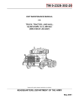
SD-08-2401
®
Bendix® AF-3™ In-Line Filter
DELIVERY
SUPPLY
1/4" NPT
SUPPLY
1/4" NPT
DELIVERY
SCREEN
SPRING
DIRECTIONAL ARROW INDICATES AIR FLOW
FIGURE 1 - AF-3™ IN-LINE FILTER SECTIONAL AND EXTERIOR VIEW
DESCRIPTION
GENERAL
The AF-3™ in-line filter assembly is designed to prevent
foreign material from entering the control port of the Trailer
ABS modulator or spring brake relay. The filter body is made
of steel with an internal screen element of stainless steel held
in place by a spring. The filter is capable of removing particles
0.012 inches in size or larger. The filter has a ¼ NPT female
supply port and a ¼ NPT male delivery port. Note: If the
filter is installed in the reversed direction, its filtering
capability will be reduced.
WARNING! PLEASE READ AND FOLLOW
THESE INSTRUCTIONS TO AVOID PERSONAL INJURY OR DEATH:
When working on or around a vehicle, the following
general precautions should be observed at all times.
1. Park the vehicle on a level surface, apply the parking brakes, and always block the wheels. Always
wear safety glasses.
2. Stop the engine and remove ignition key when
working under or around the vehicle. When working in the engine compartment, the engine should
be shut off and the ignition key should be removed.
Where circumstances require that the engine be
in operation, EXTREME CAUTION should be used
to prevent personal injury resulting from contact
with moving, rotating, leaking, heated or electrically charged components.
3. Do not attempt to install, remove, disassemble or
assemble a component until you have read and
thoroughly understand the recommended procedures. Use only the proper tools and observe all
precautions pertaining to use of those tools.
4. If the work is being performed on the vehicle’s air
brake system, or any auxiliary pressurized air systems, make certain to drain the air pressure from
all reservoirs before beginning ANY work on the
vehicle. If the vehicle is equipped with an AD-IS™
air dryer system or a dryer reservoir module, be
sure to drain the purge reservoir.
1
5. Following the vehicle manufacturer’s recommended procedures, deactivate the electrical system in a manner that safely removes all electrical
power from the vehicle.
6. Never exceed manufacturer’s recommended pressures.
7. Never connect or disconnect a hose or line containing pressure; it may whip. Never remove a component or plug unless you are certain all system
pressure has been depleted.
8. Use only genuine Bendix® replacement parts, components and kits. Replacement hardware, tubing,
hose, fittings, etc. must be of equivalent size, type
and strength as original equipment and be designed specifically for such applications and systems.
9. Components with stripped threads or damaged
parts should be replaced rather than repaired. Do
not attempt repairs requiring machining or welding unless specifically stated and approved by the
vehicle and component manufacturer.
10. Prior to returning the vehicle to service, make
certain all components and systems are restored
to their proper operating condition.
PREVENTIVE MAINTENANCE
Because no two vehicles operate under identical conditions,
maintenance intervals will vary. Experience is a valuable
guide in determining the best maintenance interval for a
vehicle. As a recommended minimum, every 12 months,
100,000 miles or 3,600 operating hours, perform the
Operational and Leakage Tests noted below. Inspect the
filter for unrestricted airflow and blockage from debris
collection. Remove the filter assembly and clean as
needed. If the unit cannot be cleaned of debris, replace the
filter. There are no serviceable parts within the assembly.
SERVICING AND CLEANING
1. Identify the control line to the trailer ABS modulator or
spring brake relay valve. Disconnect the control line and
remove the filter from the control port.
2. With the AF-3™ in-line filter removed, apply shop air to the
delivery port of the filter to clean the debris from the filter
screen.
NOTE: Disassembly/reassembly of the AF-3™ in-line
filter is not recommended. If an assembly does not
meet the Operational and Leakage Tests, it should
be replaced with a new AF-3™ in-line filter.
ECU
CONTROL
PORT
Figure 2 - Trailer Antilock Modulator
4. Apply thread sealant (do not use Teflon tape) to the
male threads of the control line and the AF-3™ in-line
filter.
5. Install the filter in the control port of the ABS modulator
or spring brake relay valve. Torque the filter body in place
to approximately 10 pound-feet.
6. Connect the control line to the supply port of the AF-3™
in-line filter.
OPERATIONAL AND LEAKAGE TESTS
Apply the brakes and hold 20 psi pressure to the line. Apply
a soap solution to the threads to check for leakage. A oneinch bubble in 5 seconds is permitted. Repair any excessive
leaks. Perform the Service Check before placing the vehicle
in service.
SERVICE CHECK
Apply and release air pressure to the control line containing
the filter. The AF-3™ in-line filter should allow delivery and
exhausting of the pressure without any noticeable delay in
service brake response. A delay can be identified by making
a service brake application and viewing the actuator push
rods. A delay may indicate foreign material is present in the
control line, preventing the proper flow of air. If a delay is
found, clean or replace the AF-3™ in-line filter.
3. Clean the contaminants from the control line by applying
shop air to the control line at the gladhand. If the trailer
is connected to the tractor, build system pressure and
make a light brake application. Caution: Pressurized
debris can cause bodily injury, be sure the area
around the trailer is vacated before performing this
operation.
BW2263 © 2004 Bendix Commercial Vehicle Systems LLC. All rights reserved. 5/2004 Printed in U.S.A.
2


![Trailer Roll Stability (TRS) Installation Manual [L30040]](http://vs1.manualzilla.com/store/data/006020641_1-040a22153212ab13bbec744ca183c148-150x150.png)