1
fORCED cONVENTION
oven
Operation and
Service Manual
Model : LFO - 250
Labnics Equipment
Table of Content
S. No.
Content
Pg. No.
1
Introduction
1
2
Safety Precautions
1
2.1
Power Connection
1
2.2
Installation
2
2.3
Operation
2
2.4
Maintenance
2
3
Features
3
4
Specifications
4
5
Parts And Description
5
6
Main Controller
6
7
Operation
7
8
Service Manual
8
8.1
Circuit Diagram
8
8.2
Frequently Asked Questions
9
8.3
Trouble Shooting Guide
9
8.4
Spare Part List
9
9
Setting Parameter
10
9.1
Parameter 1
10
9.2
Parameter 2
10
10
Inspection Log For Force Convection Oven
12
11
Maintenance And Service Check List
13
12
Certificate Of Warranty
14
13
Service Report
15
CHAPTER 1. INTRODUCTION:Thank you for choosing Labnics Laboratory Products
Please read this operation manual carefully for your safety and for the instrument having optimum
operating performance.
If you have any query, please contact our sales representative or service department.
CHAPTER 2. SAFETY PRECAUTIONS:This manual contains important operating and safety information. You must carefully read and
understand the content of this manual prior to the use of this equipment.
Warning:
Warning alert you to a possibility of personal injury
Caution:
Caution alert you to a possibility of damage to the equipment.
2.1 Power Connection:
Caution
……………………………………………….
1. Your Oven is designed for 110VAC, 60Hz 1P or 220VAC, 50/60Hz 1P.
2. Check electrical requirement given on the name plate before use. Name plate is located in electric
cord connection.
3. Connect to receptacle with ground connection.
4. Be sure to supply enough electrical current.
-1-
2.2 Installation:
Caution
……………………………………………….
1. Do not use the instrument in high humid environment
l
May cause Electrical leakage.
l
Water droplet may occur on the door.
l
Corrosion may occur.
2. Do not use it in high temperature environment or so not use besides instrument generating heat.
3. Install oven at least 100mm apart from side wall.
4. Place flat, rigid and leveled surface.
5. When moving oven do not up-side-down.
6. Do not place any object on the top of oven.
2.3 Operation:
Warning
……………………………………………….
1. Hot surface may cause injury. So always wear protective gear.
2. Do not put volatile, flammable and explosive material inside the oven.
3. Do not put volatile, flammable and explosive material nearby oven.
Caution
……………………………………………….
1. Do not spill liquid in the chamber.
2. Be careful not to spill liquid on the control panel.
2.4 Maintenance:
Caution
……………………………………………….
1. Do not pour water or any liquid when you clean oven.
2. Do not use highly organic solvent for cleaning the surface of oven.
-2-
CHAPTER 3. FEATURES:Forced Convection Oven is ideal for general laboratory drying application at high temperature range from
ambient +10 oC to 250 oC.
Controller:
o
Digital microprocessor PID Controller with ± 0.1 C resolution.
Performance:
l
Temperature Range
l
Resolution
l
Accuracy
l
Uniformity
o
o
: Ambient + 10 C ~ 250 C
: ± 0.1 oC
: ± 0.2 oC
o
: ± 1.0 C
Material:
l
Inner Chamber : Stainless Steel 304 (ANSI 304) 0.8mm thickness
l
Outer Cabinet : Steel with epoxy powder coating
l
Glass Window : Tempered Safety Glass 5mm thick Double Layer
l
High
quality dust-free aluminum barrier mineral wool with air flow layer to protect heat
dissipation to the surface of oven
Convenience:
l
Seamless round cornered edge of chamber for easy cleaning and decontamination.
l
Transparent glass Window.
l
Height adjustable shelves of 25mm increment.
Safety:
l
Over current cut-off.
l
Over temperature cut-off.
-3-
CHAPTER 4. SPECIFICATIONS:Model
Chamber Volume
Temperature
LFO-250
250L
Heating Type
Forced Convection
Range
Ambient + 10 oC ~ 250 C
Accuracy
Uniformity
Heat Up Time
± 0.2 oC at 120 oC
± 1 oC at 120 oC
within 30 minutes to 120 oC
o
Heater
2.5 kW
Controller
Digital PID Controller with Timer and Auto-Tuning
Wait off Timer
mm:ss / hh:mm / dd:hh / Continuous Selectable
Pt 100?
Sensor
Safety Device
Dimensions
(W x D x H)mm
Material
Temperature
Electrical Leakage
Limit Switch
Inner
Outer
Clearance
Window
Internal
External
Insulation
Hydraulic Over Temperature Protection Safety Device
Electrical Leakage Breaker or CG Fuse
Heater and Fan output off on door open
600 x 600 x 700
990 x 750 x 955
995 x 760 x 1005
W150 x H450
Stainless Steel 0.8 T Polished (SUS304)
Steel 1T with Epoxy Powder Coating
Mineral Wool 50 mm /w Woven Aluminum Barrier
Door Gasket
High Temperature Resistance Foamed Silicone Rubber
Window
Double Layer Tempered Safety Glass 5T
Shelves
Wire Shelve with Chrome Pleated
No of Shelves Included
3
Adjustable Height Between Shelves
25 mm increment
Maximum No of Shelves
24
No of Ventilation Damper
1
Power Consumption
12.3 A
Electrical Requirement
Net Weight
Shipping Weight
Catalog No.
220 VAC 50/60 Hz or 120 VAC 60Hz
72 kg
82 kg
08150503
-4-
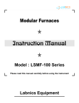
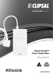
CHAPTER 5. PARTS AND DESCRIPTION:Damper
Main Controller
Windows
Door Catch
Power Cord
Circuit Breaker
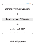
CHAPTER 6. MAIN CONTROLLER:-
LED Display
Pilot Lamp
Shift (AT) Butt
Mode Button
INC (DSO) Butt
Over-Temp. Cut
Power Switch
LED Display
Digital LED Display
Displays current chamber temperature when turned on.
Press INC button to display remaining time when wait-off timer gets activated.
-5-
Pilot Lamp
Pilot Lamp
TIMER: Lamp blink or turned on when wait-off timer gets activated.
Lamp blinks until temperature reached upto operating temperature.
Lamp turned on to start count down.
HEATER OUTPUT: Lamp blinks when heater is activated.
Buttons
Mode Button
l
Push to Change temperature and time setting.
l
Push to change parameters.
l
Push and hold for 20 seconds to enter the instrument in parameter mode.
(Remarks) Operating parameters are set before shipment. Do not change
without the knowledge of each function of parameters.
Shift (At) Button
l
Shift to left digit
Auto Tuning Function
Press and hold for 30 seconds to start auto-tuning.
Auto-tuning will get finished before shipment.
INC (DSP) Button
l
Increase value when setting temperature and timer.
l
Press to display temperature & timer alternatively in normal display mode.
SAFETY
l
Safety dial for over temperature cut-off.
l
Set dial 10 ~ 20% higher than operating temperature
l
If temperature rise over operating temperature, safety automatically cut-off
heater output to prevent over heating.
POWER SWITCH
l
Main power switch.
-6-
CHAPTER 7. OPERATION:Before Operation:
1) Check electrical requirement on the name plate before
connecting it to consent.
2) Remove packing material in the chamber and install shelves.
3) Connect power plug between AC inlet consent on the left side
of panel and wall mount receptacle.
How to Set Temperature:
1) In normal display mode.
2) Press MODE button.
3) LED displays " TEMP " symbol and prompt user Input.
4) Press MODE button again.
5) LED displays current operating temperature.
6) Enter new operating temperature by using SHIFT and INC
button.
7) You can enter operating temperature range from ambient
+5 oC to 250 oC.
8) Press MODE button to set timer.
9) Press model button three times to skip timer Setting.
How to Set Timer:
1) Press MODE button twice to set timer.
2) LED displays " TIME " symbol and prompt user input.
3) Press MODE button again.
4) LED displays current timer setting. (ex. 00:00 )
5) Input new wait-off timer value by using SHIFT & INC button.
6) Default time scale is HH:MM.
6) For continuous operation set timer at 00.00.
4) You can enter time range from 1min to 99hr 59min.
5) Press MODE button to go back to normal display mode.
(Remarks)- Timer can be changed in different scale by changing parameters
Parameters are:1) mm : ss --- 1 sec ~ 99 min 59 sec
2) hh : mm --- 1 min ~ 99 hr 59 min
3) dd : hh --- 1 hr ~ 99 day 23 hr
refer parameter setting to change time scale
MODE 0, N1 : time scale selection parameter
0 : mm:ss
1 : hh:mm
2 : dd:hh
-7-
Over Temperature Protection:
1) User must set the over temperature protection before
operation.
2) Turn over temperature protection dial with screw driver.
3) Set temperature about 10~20% higher than the operating
(user set) temperature.
4) If over-temp. protection value is below the operating
temperature, temp. cannot be reach upto operating temp.
Operation:
1) While setting temperature and time, close door to start
temperature control.
2) If you open the door during operation, blower fan and heater
stops automatically.
3) Open damper on the top of your oven to vent out vapor.
4) If you keep close damper during operation, temperature
over-shooting may occur.
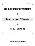
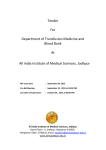
CHAPTER 8. SERVICE MANUAL:8.1 Circuit Diagram
LFO 250
-8-
8.2 Frequently Asked Questions:
1) Why temperature keeps on increasing and decreasing under set temperature?
Cause: SAFETY setting is lower than the set temperature.
Solution: Turn "SAFETY setting" clockwise higher than the set temperature.
2) Why sometimes temperature does not increase?
Cause: Door switch contact.
Solution: Adjust the height of door-switch for safety purpose when the door is close.
3) Temperature Overshoot?
Cause: Insulation and closed system.
Solution: Open damper to vent out chamber air to outside.
4) LED displays uuuu and beep?
Cause: Over heating, higher than 250oC
Solution: Your incubator cannot be used over 250oC.
If temperature increases over 250oC, controller will show a warning "high temperature" and cut-off heater.
8.3 Trouble Shooting Guide:
Error Symbol
uuuu
nnnn
Cause
o
Over heat higher than 250 C
Sensor disconnection
Solution
Call for Service
Call for Service
Descriptions
Damper
Tempered Glass
Door Catch
Silicone Packing
Hinge (top)
Shelf
Shelf Support
Main Controller
Power Switch
Incolony Heater
Safety Thermostat
Pt100 Sensor
Door Switch
TRIAC
Heat Sink
Circuit Breaker
Blower Motor
Fan Blade
8P Relay
8P Relay Socket
LFO 250
8.4 Spare Part List:
Part No.
OF-HD-01
OF-HD-02
OF-HD-03
OF-HD-04
OF-HD-05
OF-HD-06
OF-HD-07
OF-ED-01
OF-ED-02
OF-ED-03
OF-ED-04
OF-ED-05
OF-ED-06
OF-ED-07
OF-ED-08
OF-ED-09
OF-ED-10
OF-ED-11
OF-ED-12
OF-ED-13
180x390x5T
D-414
570 x 580
L-0-v06
8206BG
2.5 kW
TS-320
PT-100 ? M10
YSP9S-15C
TG25C
100*100
220V 30A
D150 x H62 CCW
HR710-2PL
KLY2
-9-
CHAPTER 9. SETTING PARAMETER:9.1 Parameter 1:
1) To set parameters, press and hold "MODE" Button for 5 seconds.
2) Press "SHIFT" and "INC" Button to change values.
3) Press "MODE" Button to go to next parameter.
4) To escape from parameter mode to normal display mode, press & hold "MODE" Button for 5 seconds.
Parameter Symbol
ALH
Name of Parameter
Alarm Limit High
Setting Range and Descriptions
Factory Default
o
2.0
o
21.0
o
00.0 ~ 99.9 C
ALL
Alarm Limit Low
00.0 ~ 99.9 C
HYS
Hysteresis
00.0 ~ 99.9 C
0.2
BEEP
Beep On Time
0 ~ 9999 Sec.
30
ADJ
Temperature Calibration
LOC
Key, Data, Parameter Lock
User Value
o
-99.9 ~ 299.9 C
0000 ~ 1111
0000
9.2 Parameter 2:
1)
2)
3)
4)
5)
To set parameters, press and hold "MODE" Button for 30 seconds.
LED Display turn to "ALH" after 5 seconds. Press the button for 25 seconds.
Press "SHIFT" and "INC" Button to change values.
Press "MODE" Button to go to next parameter.
To escape from Parameter mode to normal display mode, press & hold "MODE" Button for 5 seconds.
Setting Range and
Parameter
Symbol
Name of Parameter
Descriptions
o
RNT
Maximum temperature limit to set
-99.9 ~ 299.9 C
o
ACTP
Temp. where timer activate
-00.0 ~ 99.9 C
(Parameter can be changed only when the N2 value of Mode0 is 1)
Timer starts count down when, (current temp. - set temp.) > ACTP
Prd
Period (Output Interval)
1 ~ 99 sec.
P
Proportion
0 ~ 6999
I
Integral
0 ~ 6999
A
Anti-Intergran
0 ~ 6999
D
Differential
0 ~ 6999
Mode0
Operating Mode Control 0
N3
0 = KS, JIS Pt 100
1 = DIN Pt 100
N2
0 = ALH (Relative)
N3 N2 N1 N0
1 = AALH (Absolute)
0 0 0 0
N1
0 = ALL (Relative)
1 1 1 1
1 = AALL (Absolute)
N0
0 = 000oC
1 = Decimal display (000.0oC)
Mode1
Operating Mode Control 1
N3
0 = PID Control
1 = ON/OFF Control
N2
0 = Timer Disable
N3 N2 N1 N0
1 = Timer
0 0 0 0
N1
0 = Time Scale ( mm:ss)
1 1 1 1
1 = Time Scale ( hh:mm)
2 = Time Scale ( dd:hh)
N0
0 = Power on restore disable
1 = Power on restore
- 10 -
Factory Default
251
0
User Value
Do Not Change
2
Auto-tuned value
Auto-tuned value
Auto-tuned value
Auto-tuned value
Do Not Change
Do Not Change
Do Not Change
Do Not Change
Do Not Change
0001
Do Not Change
0111
1) RNT : Maximum temperature limit to set.
User cannot set temperature higher than this value.
Do not alter the value. Factory default is 251.
2) ADJ : Temperature adjustment.
- Sometimes the actual temperature of water is slightly different from the displayed temperature.
- User can adjust the displayed temperature by compensating the difference by Adj value.
Example
1) Measure temperature of Incubator with calibrated thermometer.
2) Read LED display.
3) Change Adj value.
Thermometer
Temperature Reading
Controller
Temperature Reading
Adj Value
120.0 oC
119.0 oC
1
121.0 oC
120.0 oC
-1
CHAPTER 10. INSPECTION LOG FOR FORCED CONVECTION OVEN:Model:
Serial:
Client:
Date & Time:
Amb. Temp.:
Electricity: VAC Hz
LFO-250 Pretest check list (Initial after each Checkpoint)
If Non-Applicable enter N/A
Termination of each electrical connections
Battery termination light
No metal contact with refrigeration tubes
Control panel key switch tight
N/A
N/A
Termination of remote alarm
Surge protection termination
No gaps in insulation
Equipped with proper accessories
Esthetics ok
- 11 -
N/A
LFO-100 TEST AREA, TEST LOG (NOTE) If units fails any portion of the test enter "NG" in the
blank space adjacent to that check point
Technician
Unusual vibration during run
Volts at plug / terminal strip / Hz
Unusual noise during run
Fans-Correct blade, no contact
Unusual fan noise or vibration
Battery Check 12 volts or better
N/A
Display indication and warning functions
Battery % reading from display
N/A
Leakage or condensation on the tubes
N/A
Cut in voltage
Back Up system
N/A
Display voltage
No condensation on cabinet at BO
N/A
Surge
Check frost on door and interior
N/A
Check Fuse LED
Lid/door seal at pulldown
RS232
N/A
Door close and latches
Alarm/remote operation
N/A
Setpoint security verified
Unusual noise at startup
Labeling on components correct
No excessive dummy panel vibration
Molded plug not overheated
Recorder check and calibrated
N/A
No frost on refrigeration components
N/A
Leakage on the water pipe line
N/A
Breaker fit at low temperature
N/A
Verify solenoid valve
N/A
Leak check while running
Verify over temp. protection of chamber
Verify over temp. protection of humidity heater
Verify motor voltage (verify color code)
N/A
Check fluorescent lamps and lights
Released from test by :
From#QCF001frm
Approval :
- 12 -
N/A
CHAPTER 11. MAINTENANCE AND SERVICE CHECK LIST:Maintenance and Service Check List
Model
LFO-250
Descriptions
Forced Convection Oven
Serial No.
Date
Check
Technician
Remarks
Sign
Shipment
¡
Check ¤
Clean-Up
Article
Every 6 Month
Every Year
¨
Replace
Every 2 Year
Controller
¡
PT Sensor
¡
Heater
¡
Blower Motor
¡
TRIAC
¡
¤
OPT
¡
¤
Main S/W
¡
- 13 -
CHAPTER 12. CERTIFICATE OF WARRANTY:Descriptions
Model
Serial No.
Warranty Period
Date of Purchase
Purchase From
Forced Convection Oven
LFO-250
12 Months after purchase
WARRANTY COVERAGE
Labnics's warranty obligations for the products are limited to the
terms set forth below:
Labnics warrants the product against defects in materials and
workmanship for a period of one (1) year from the date of original
purchase ("Warranty Period"), providing that the unit is operated
according to the instruction in the operating manual.
The guarantee comprises removal of all damages that arises
during the guarantee period and that are proven to be due to
faulty material or poor workmanship.
If a defect arises and a valid claim is received by Labnics within
the Warranty Period, at its option, Labnics will (1) repair the
product at no charge, using new or refurbished replacement
parts, (2) exchange the product with a product that is new or
which has been manufactured from new or serviceable used
parts and is at least functionally equivalent to the original product.
If a defect arises and a valid claim is received by Labnics after the
first one hundred and eighty (180) days of the Warranty Period, a
shipping and handling charge will apply to any repair or
exchange of the product undertaken by Labnics.
Labnics warrants replacement products or parts provided under
this warranty against defects in materials and workmanship from
the date of the replacement or repair for ninety (90) days or for
the remaining portion of the original product's warranty,
whichever provides longer coverage for you. When a product or
part is exchanged, any replacement item becomes your property
and the replaced item becomes Labnics's property. When a
refund is given, your product becomes Labnics's property.
EXCLUSIONS AND LIMITATIONS
This Limited Warranty applies only to the product manufactured
by or for Labnics that can be identified by Name Plate.
Labnics is not liable for any damage to or loss of any products or
material stored or tested in the instruments or programs, data, or
other information stored on any media contained within the
product, or any non-Labnics product or part not covered by this
warranty. Recovery or reinstallation of programs, data or other
information is not covered under this Limited Warranty.
This warranty does not apply: (a) to damage caused by accident,
abuse, misuse, misapplication, or non-Labnics products; (b) to
damage caused by service performed by anyone other than
Labnics; (c) to a product or a part that has been modified without
the written permission of Labnics; or (d) if any Labnics serial
number has been removed or defaced; or (e) if the unit is not used
according to its purpose; or (f) no original spare parts are used.
TO THE MAXIMUM EXTENT PERMITTED BY LAW, THIS
WARRANTY AND THE REMEDIES SET FORTH ABOVE ARE
EXCLUSIVE AND IN LIEU OF ALL OTHER WARRANTIES,
REMEDIES AND CONDITIONS, WHETHER ORAL OR
WRITTEN, EXPRESS OR IMPLIED. LABNICS SPECIFICALLY
DISCLAIMS ANY AND ALL IMPLIED WARRANTIES,
INCLUDING, WITHOUT LIMITATION, WARRANTIES OF
MERCHANTABILITY AND FITNESS FOR A PARTICULAR
PURPOSE. IF LABNICS CANNOT LAWFULLY DISCLAIM OR
EXCLUDE IMPLIED WARRANTIES UNDER APPLICABLE
LAW, THEN TO THE EXTENT POSSIBLE ANY CLAIMS
UNDER SUCH IMPLIED WARRANTIES SHALL EXPIRE ON
EXPIRATION OF THE WARRANTY PERIOD. No Labnics
reseller, agent, or employee is authorized to make any
modification, extension, or addition to this warranty.
TO THE MAXIMUM EXTENT PERMITTED BY LAW, LABNICS
IS NOT RESPONSIBLE FOR DIRECT, SPECIAL, INCIDENTAL
OR CONSEQUENTIAL DAMAGES RESULTING FROM ANY
BREACH OF WARRANTY OR CONDITION, OR UNDER ANY
OTHER LEGAL THEORY, INCLUDING ANY COSTS OF
RECOVERING OR REPRODUCING ANY PRODUCT OR
MATERIAL STORED OR TESTED IN THE INSTRUMENTS,
PROGRAM OR DATA STORED IN OR USED WITH THE
LABNICS PRODUCT, AND ANY FAILURE TO MAINTAIN THE
CONFIDENTIALITY OF DATA STORED ON THE PRODUCT.
LABNICS SPECIFICALLY DOES NOT REPRESENT THAT IT
WILL BE ABLE TO REPAIR ANY PRODUCT UNDER THIS
WARRANTY OR MAKE A PRODUCT EXCHANGE WITHOUT
RISK TO OR LOSS OF MATERIAL, PROGRAMS OR DATA.
FOR CONSUMERS WHO HAVE THE BENEFIT OF
CONSUMER PROTECTION LAWS OR REGULATIONS IN
THEIR COUNTRY OF PURCHASE OR, IF DIFFERENT, THEIR
COUNTRY OF RESIDENCE, THE BENEFITS CONFERRED
BY THIS WARRANTY ARE IN ADDITION TO ALL RIGHTS AND
REMEDIES CONVEYED BY SUCH CONSUMER
PROTECTION LAWS AND REGULATIONS. TO THE EXTENT
THAT LIABILITY UNDER SUCH CONSUMER PROTECTION
LAWS AND REGULATIONS MAY BE LIMITED, LABNICS'S
LIABILITY IS LIMITED, AT ITS SOLE OPTION TO
REPLACEMENT OR REPAIR OF THE PRODUCT OR SUPPLY
OF THE REPAIR SERVICE AGAIN.
Note: Before you deliver your product for warranty service it is your responsibility to remove all products or materials stored in the
instrument. Before returning a defective unit, please contact local representative or Labnics Support Center at [email protected].
Labnics will issue RGA number for authorized return; If we agree to the unit being returned, arrange for careful packing and send the
unit to LABNICS.
- 14 -
SERVICE REPORT
Tel.No.:
Customer’s Address :
Fax No.:
Weekly Off.:
Dept.:
Contact Person / Designation :
Time
Date
From
To
System
Configuration
Date :
Model
SR. No.
Serial No.
Status : OK
Installation
Not OK
Warranty
Demonstration
Maintenance
Contract
Repairs
Application
Billable
Calibration
Validation
Courtesy
Nature of Problem :
Observation & Action Taken :
Customer’s Remarks :
Parts Replaced :
Parts Recommended / Action Required : Yes
No
Service Engineer’s Name & Signature
Requisition Number :
Customer’s Name, Signature, Date & Stamp
Page ____ Of ____
- 15 -