1
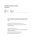
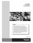
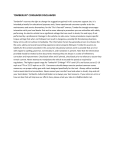
TOMBERLIN® CONSUMER DISCLAIMER Tomberlin® reserves the right to change the suggestions gained in this consumer support site. It is intended primarily for educational purposes only. Some experienced consumers prefer to do the maintenance and service themselves, for the "Do It Yourself" owners, Tomberlin strongly encourages interaction with your local dealer first and to never attempt a procedure you are unfamiliar with safely performing. An electric vehicle has a significant voltage that can result in shock, fire and injury if not performed by a professional. Damage to the vehicle can also occur. Some procedures require specific torque settings that when not followed can result in dangerous, possibly life threatening situations. Many errors will not surface immediately. The information herein has generally proven to enhance the life cycle, safety and overall ownership experience when properly followed. Tomberlin assumes no liability for the content provided in this consumer educational section and it is possible that an error with regard to spelling, grammar, nomenclature, and translation is present. Note that the information provided should be treated as live documents meaning they are always in a state of refinement, correction and improvement. Check back often and if printed, check back prior to reliance to assure they remain current. Never attempt to manipulate the vehicle to exceed the speed as required by regulations. The highest speed range for Tomberlin® E‐Merge™ PTV's and LSV's are factory set at 15‐19 mph as a PTV or 22‐25 mph as an LSV. Consumers should always exercise prudent common sense measures, use proper safety gear with tools designed specifically for the task. Always utilize insulated tools around electrical connections. Never exceed your comfort level and when in doubt, stop and call your local dealer. Tomberlin Authorized Dealers are always your best resource. If you notice an error or have an idea that will improve our efforts here, please email your idea to [email protected]. ANVIL OPERATOR’S MANUAL Electric Low-speed Vehicle (LSV) Anvil Operator’s Manual Page 1 WARNING z THE TOMBERLIN ANVIL IS EQUIPPED TO OPERATE AT A TOP SPEED OF 25MPH (40 KPH) AND IS INTENDED FOR USE AS A LOW-SPEED-VEHICLE. WARNING WHEN OPERATING VEHICLE ON PUBLIC ROADS THIS VEHICLE OFFERS MUCH LESS CRASH PROTECTION THAN A NORMAL PASSENGER CAR, VAN, OR TRUCK. THIS MEANS A HIGHER RISK OF INJURY OR DEATH ON COLLISIONS, EVEN AT LOW SPEEDS. THE HIGHER THE SPEED OF THE TRAFFIC AROUND YOU, THE HIGHER THE RISK OF INJURY MAY OCCUR. To reduce these risks: z z z z z z z Obey all traffic regulations. Avoid roads with regular traffic, even if the speed limit is low. Whenever possible, stay on roads and lanes limited to low speed vehicle. All passengers should wear safety belts at all times. Avoid operating vehicle at night if possible, because your vehicle may be hard for others to see. To reduce the chance of the vehicle tipping over, reduce speed when turning and maneuvering through curves and hills. Never drink and drive. Not only is drinking and driving unsafe, but doing so may violate state and local laws. WARNING THIS PRODUCT CONTAINS OR EMITS CHEMICALS OR SUBSTANCES THAT HAVE BEEN DETERMINED BY THE STATE OF CALIFORNIA TO CAUSE CANCER AND BIRTH DEFECTS OR OTHER REPRODUCTIVE HARM. Anvil Operator’s Manual Page 2 WARNING • • • This vehicle is not designed to be used in conjunction with child safety seats Do not use or install child safety seat in any seat or position in the vehicle Always obey and follow laws and regulations regarding the transportation of children • Children that require the use of a child safety seat in a regular type automobile should not be transported in this vehicle Anvil Operator’s Manual Page 3 Foreword Thank you for the purchase of your Tomberlin Anvil. Your satisfaction with your new vehicle is important to all of us at Tomberlin. Please take the time to review this Operator’s manual and abide by all safety and operation warnings before allowing anyone to operate your new Anvil. Familiarizing yourself with the Operator’s Manual and warnings will help avoid possible personal injury and property loss. We hope that you will consider this manual as an indispensable part of the vehicle. The information contained in this document is subject to change without notice. Tomberlin reserves the right to make design changes to vehicle without obligation to make these changes on units previously sold. IMPORTANT OPERATING NOTES: z z z z ALWAYS OPERATE YOUR ANVIL IN COMPLIANCE WITH YOUR STATE AND LOCAL VEHICLE REGULATIONS INCLUDING REGISTRATION, TITLING, INSURANCE, SEAT BELT USAGE, AND OPERATOR’S LICENSING. SWITCH VEHICLE TO OFF POSITION, REMOVE KEY AND SET PARKING BRAKE PRIOR TO EXITING DRIVER’S SEAT. ALWAYS FASTEN YOUR SEAT BELTS! TO EXTEND THE LIFE OF YOUR BATTERIES: ° KEEP BATTERIES FULLY CHARGED WHENEVER POSSIBLE. ° AVOID DEEP DISCHARGING OF BATTERIES WHENEVER POSSIBLE ° USING THE BATTERY WATERING SYSTEM, ADD DISTILLED WATER AS NECESSARY. ° ALWAYS WEAR SAFETY GOGGLES OR EYE PROTECTION, RUBBER GLOVES, AND A MASK BEFORE HANDLING BATTERIES. ° KEEP YOUR ANVIL PLUGGED INTO THE CHARGER EVEN DURING LONG ABSENCES. THE CHARGER IS COMPUTER CONTROLLED AND WILL MONITOR AND MAINTAIN YOUR BATTERIES PEAK CONDITION. ° WHEN NEW(FIRST 4 WEEKS)AND UNDER HEAVY USE CHECK ELECTROLYTE BY REMOVING THE BATTERY CAPS TO INSURE THAT THE WATERING FREQUENCY RATE IS MAINTAINING THE PROPER ELECTROLYTE LEVEL. Anvil Operator’s Manual Page 4 CONTENTS Precautions ------------------------------------------------------------------6 Safety Regulations---------------------------------------------------------6 General Warnings-----------------------------------------------------------6 Appearance of Control-----------------------------------------------------8 Controls And Operation---------------------------------------------------9 Pre-operation Inspection-------------------------------------------------14 Driving Instructions--------------------------------------------------------15 Towing--------------------------------------------------------------------------16 Storage-------------------------------------------------------------------------16 Maintenance------------------------------------------------------------------17 - Scheduled Maintenance----------------------------------------------18 - Battery Pack--------------------------------------------------------------21 Charger-------------------------------------------------------------------------23 Cleaning -----------------------------------------------------------------------26 Vehicle Specifications-----------------------------------------------------27 Warranty------------------------------------------------------------------------28 Anvil Operator’s Manual Page 5 PRECAUTION The Anvil is designed and manufactured as a Low-Speed-Vehicle (LSV). It is important that every Operator become familiar with safe operation of the vehicle as described in this Operating Manual and also with all applicable State, Local, and Community regulations governing the use of an LSV. SAFETY REGULATIONS It is required to read the Owner’s manual completely before operating the vehicle or attempting repair work. Any violations of instructions in the manual may lead to property loss, serious injury, or even death. Pay special attention to important statements with the words such as “Danger”, “Warning”, “Caution”, “Attention” etc… If any of the operation/warning decals are damaged, defaced, destroyed, or illegible it is important that they be replaced with new decals. Please contact the manufacturer or your dealer to obtain new decals. DANGER DANGER indicates an immediate hazard that if ignored, will result in severe personal injury or death. WARNING WARNING indicates an immediate hazard that if ignored, could result in severe personal injury or death. CAUTION CAUTION indicates a hazard or unsafe practice that if ignored, could result in minor personal injury or product or property damage. GENERAL WARNINGS The following safety procedures should be followed during vehicle operation, maintenance or repair. Other special warning signs are described in this manual. DANGER Anvil Operator’s Manual Page 6 The Anvil contains batteries which can emit quantities of explosive gases. Keep the vehicle in a well ventilated area and away from sparks and open flames. Ventilate when charging or operating the vehicle in enclosed areas. Do not perform service or maintenance on batteries while vehicle is charging. The Anvil does not offer protection from lightning, flying debris, or other storm hazards. Upon indication of severe weather condition, seek appropriate shelter immediately. WARNING Inspect battery terminals, cables and batteries before each use. Always wear a full face shield, rubber gloves and rubber apron when working with or in close proximity to batteries. Turn the ignition switch to the off position Turn the ignition switch to the off position, remove the key, set the park brake, unplug the charger and place the run/tow switch to the two position before inspecting or performing any type of service on the vehicle. Connections should be tight and free of corrosion. Utilize insulated tools only when working with electrical connections. The tightness of the battery terminal nut should be between 95-105 inch pounds of torque. Do not over tighten. Loose and/or over tightened connections can cause battery failure, explosion and or fire. Do Not Overfill the Batteries and keep batteries clean and free of moisture. If any high heat condition or burning smell is noticed immediately park the vehicle in a safe location, place the ignition in the off position, move yourself and passengers away quickly to a safe distance from the vehicle and contact your dealer for assistance and repair. If fire or smoke is detected contact your local fire department immediately. Do not store your vehicle inside if any of these conditions exist. Only use recommended batteries of the correct size. Only authorized mechanics should perform maintenance or repair on the Anvil. It is required to abide by all regulations and safety decals on the vehicle while performing any type of maintenance or repairs. To carry out repair work: turn the run/tow switch to the “TOW” position. Turn the vehicle off, remove the key and chock the tires. Set the direction selector to its Neutral position. Use only insulated tools to handle the battery pack and electrical components. Remove all jewelry and loosen items before performing maintenance procedures. Improper application or maintenance will lead to deterioration of vehicle performance Anvil Operator’s Manual Page 7 and reduce the overall life of the vehicle. Do not attempt to alter the vehicle in any manner which would affect stability, control, or top speed. Such alterations may lead it serious injury or death, violate state and local laws, and will void the manufacturer’s warranty. APPEARANCE OF THE ANVIL CONTROLS 1. Headlight & turn signal stalk 2. Brake fluid reservoir 3. Steering wheel 4. Speedometer/ Instrument Display 5. Windshield wiper control and defroster switch 6. CD player / Stereo (reference stereo manual ) 7. Defroster vent 8.12V Power outlet (max 5 AMP rating) 9. Speaker 10. Charge indicator Anvil Operator’s Manual Page 8 15. Cup holder 16. FWD/REV switch 17. Emergency flasher switch 18. Key switch 19. Heated Seat switch 20. Parking brake handle 21. Boost button 22. High performance switch 11. Brake pedal 12. Accelerator pedal 13. Front vent handle 14. Defroster Key Switch The key switch is located on the right side of steering wheel. The key can only be removed in the OFF Position. When you turn the key to this position, all the electrical power will be turned on. WARNING z z Do not take out the key while driving your car as it will result in sudden power loss and braking to occur. Do not leave the key in the car or leave children in the vehicle unattended. Instrument Cluster 1. Amperage display 2. Left turn signal indicator 3. Trip odometer reset 4. Speed display 5. Odometer display 6. Right turn signal indicator 7. Battery Power gauge 8. Voltage display 9. Parking brake indicator 10. Brake fluid low indicator 11. High beam indicator 12. Low beam indicator 13. Motor over temperature indicator CONTROLS AND OPERATION WARNING Anvil Operator’s Manual Page 9 z z z It is imperative that all operators of the Anvil be familiar with the controls prior to operation. To avoid unintentional acceleration and vehicle damage, do not turn the direction selector switch (forward/reverse) until the vehicle has come to a complete stop. Always set the parking brake and remove the key when parking or leaving the vehicle unattended. Direction Selector Switch The direction selector switch is located on the steering column. It has three selections, FWD for Forward, REV for Reverse and a Neutral toggle position located halfway between the forward and reverse positions. IMPORTANT NOTE: This vehicle is equipped with OIC™ (Operator In Charge™) Technology. For Safety, the vehicle must be placed in the neutral position before the ignition switch is turned on, it must also be placed in neutral when changing between Economy and High Performance modes, again for safety the vehicle will only start in economy mode if the vehicle was left in High Performance mode when shut off it will need to be switched out of High Performance to Economy and then back to High Performance while in neutral if that is the initially desired driving mode. Multifunction Stalk The Multi-Function Stalk is a multi-feature control. It is located on two sides of the steering wheel and functions similar to an automobile for turn signaling, headlight (High beam and low beam), horn control, windshield wiper and defroster button. Turn Signal Anvil Operator’s Manual Page 10 Pushing downward on the stalk indicates a left turn, pushing upward a right turn. Note: the turn signal is self cancelling. It will automatically return to the off position after a turn, if it does not the operator should manually move the stalk to the center position upon completing each turn. Horn To activate the horn, depress the button on end of the turn signal stalk. Trip Odometer To reset the trip odometer depress the reset button and Hold for Three seconds. To change the reading from miles to kilometers depress and hold the reset button for Six seconds. Headlights Turn the multi-function stalk point to the headlight position. The headlamps will illuminate and the stalk will continue to function the same for turn signaling and horn. Windshield Wiper Turning the right side stalk to “INT”, ”LO” or ”HI” position, the wiper will work as Intermittent, low speed or high speed. Defroster Switch Pushing up on the right side stalk will activate the front windshield defroster (if your vehicle is equipped with this option) Boost Button Located on the left side of the steering column. When the boost button is depressed, the indicator lamp on the display will illuminate and the drive of the vehicle will boost up for approximately 30 seconds. This can be in traffic or uphill, when the vehicle is in economy mode. High Performance Switch The high performance switch is located on the left side of the steering column. To activate High Performance mode, stop the vehicle place it in neutral and depress the HP switch. The light on the switch will illuminate and also the HP symbol will illuminate on the display Heated Seat Switch Anvil Operator’s Manual Page 11 Located next to the hand brake. Press forward or rearward to the designated position, when the indicator lamp is on, the seat will heat itself either in high or low as desired. Parking Brake The Anvil is equipped with a hand operated parking brake positioned between the seats. Pull the handle upward to engage the parking brake. The longer distance it is pulled, the stronger the parking. In order to release the brake, pull the handle upward slightly, and press the button which is located in the front of handle at the same time, and then place the handle in the original position. IMPORTANT NOTE: The vehicle will not operate if the parking brake is engaged To prevent the vehicle from rolling, this brake should be applied whenever the vehicle is parked or left unattended. If the Parking Brake is engaged while the key switch is in the on position, a red (P) light will illuminate on the Instrument Cluster indicating the parking brake is engaged. WARNING ● The direction switch should be placed in the neutral position the high performance switch placed in the economy position, and the parking brake applied with the key removed whenever the operator exits the vehicle Brake Pedal The brake pedal is the larger foot pedal to the left of the accelerator pedal. The brake pedal engages all four of the Anvil brakes for shorter stopping distances. To slow the vehicle down, the operator should depress the brake pedal. Accelerator Pedal The accelerator pedal is the smaller pedal to the right of the brake pedal. When depressed, the accelerator pedal will engage the drive motor in the direction the FWD/REV switch is set. z z The vehicle will accelerate up to its top speed of just under 25 mph at which time power will be reduced to the motor. When driving in High Performance mode, top speed in economy mode is 20 mph. When the reverse position is selected, vehicle speed is reduced. Anvil Operator’s Manual Page 12 z z Smooth, slow acceleration will substantially increase the vehicle range. Always remember to disengage the parking brake prior to operating the vehicle. Accelerator pedal operation Manual parking brake operation Brake pedal operation Power outlet Located to the right of the CD player. The power output is DC12-13.5V and rated for a Maximum Amp draw of 5A. Safety Belts The Anvil has two front seats and one rear bench seat and is equipped with four safety belts, one for the driver and the others for the passengers. The safety belts should be used at all times while operating the vehicle. The Anvil is not equipped for child safety seats or infant carrying seats. Children under 12 years of age should be transported in a full size car with appropriate child restraints. Pregnant, disabled, or injured persons should consult their doctor for specific recommendations before operating the Anvil. To properly secure the seatbelts, pull the metal tab out away from the retractor and insert into one of the two the buckles located near the center of the seat. A click will be heard when the tab is securely latched. Properly adjust and ensure a snug fit by pulling the shoulder portion upward. The retractor will lock the belt during sudden stops. It may also lock if the person leans forward too quickly. Slow, easy motions will allow for free travel. To release the safety belt, press the buckle release button and allow the belt to retract. If the belt does not retract, check for kinks or twists in the belt. Anvil Operator’s Manual Page 13 WARNING z z z z z Always operate the vehicle with seat belts properly fastened. Make sure the seat belts are latched securely and are free from twists or kinks. Position the shoulder belt across the top of the shoulder. Do not place the shoulder belt under an arm. Loose fitting safety belts significantly reduce protection. Keep belts snug and positioned low on the hips. Do not exceed the recommend number if occupants for the vehicle: Maximum occupants rating is Four Persons CAUTION z z z Inspect the safety belt webbing and hardware periodically. Check for cuts, frays or loose parts. Replace components if excessive wear or damage is noticed. Keep safety belts clean and dry. To clean, use mild soap and warm water. Do not use bleach, dye or abrasive cleaners as this will weaken the belt webbing material. Do not insert any foreign objects into the retractor mechanism. Periodically check for smooth operation and replace if the mechanism is not operating properly. PRE-OPERATING INSPECTION Each vehicle has been thoroughly inspected by both the manufacturer and dealer. Before the initial operation, it is important that the user inspect the vehicle using the following guidelines: The following items should be checked on a daily basis prior to vehicle operation: z z z z z z z z z z General, check that all parts are securely fastened to the vehicle, no parts are missing, and all screws or nuts are properly tightened. Review all warning decals and placement on the vehicle. Safety Belts – visually inspect and test for safe operation. Tires – check for proper inflation as identified on the vehicle Certification Label. Batteries – Fill electrolyte level in all cells of each battery. Add distilled water as described in the Battery Care section of this manual. All wires should be free of corrosion. Batteries should be fully charged before first use of vehicle. Brakes – check hydraulic fluid level. If it is low, immediately call a qualified mechanic for service. Charger cord, plug, and receptacle inspect for cracks, loose connections, or frays. Forward/Reverse Switch – ensure proper operation Brakes – make sure the brake pedal is operating smoothly. The vehicle should come to a smooth stop when operating. If excessive or low pedal pressure, pulling to one side or unusual noise is noticed while braking, have the vehicle serviced immediately. Parking Brake– make sure the hand operated parking brake is functioning properly. The parking brake should engage the rear tires when in the up position and allow the Anvil Operator’s Manual Page 14 z z z vehicle to roll smoothly when in the released position and tow switch is placed in the tow position. Reverse Buzzer – the reverse buzzer should sound when the key is in the on position and the direction is set to reverse. Steering – steering should be smooth and consistent with no excessive play in the steering wheel. General – listen for any unusual noises such as squeaks or rattles. Check the vehicle’s ride and performance. Have a certified Tomberlin Automotive Group authorized technician investigate anything unusual. General Operation z Motor Braking the top speed of the Anvil is limited to 25 mph. The motor will engage to limit the top speed of the vehicle. The motor acts as a generator, transferring some of the excess energy into a charging for the batteries. z Regenerative Braking the Anvil will also apply some slight motor braking while stopping. A slight extra force may be felt while coming to a complete stop. This indicates a transfer of some of the excess energy back into the batteries. DRIVING INSTRUCTIONS WARNING z z z z z z z z z z z z z z z All drivers must have a valid driver’s license. Always wear seat belts. No more than four occupants at one time on Anvil. Do not carry children on your lap or between the seats. Do not allow anyone to hang onto any part of the vehicle while operating. Obey all traffic regulations. Ensure all persons have read the operator’s manual and can properly operate the vehicle. Ensure the passengers can properly operate the safety belts before allowing them to ride. Avoid operating at night because the vehicle may be difficult to see by others. If the vehicle must be operated at night, make sure you use headlamps and tail lamps. Bring the vehicle to a complete stop prior to shifting between FWD/REV. Failure to do so may injure an unsuspecting passenger and/or damage the vehicle. Operate the vehicle from the driver’s seat only. To help prevent from the risk of serious injury, driver and passenger should keep all body parts inside the vehicle at all times. Avoid sudden and sharp turns. To reduce the chance of the vehicle tipping over, reduce speed while making sharp turns. Never drink and drive. Not only is drinking and driving unsafe, but it may also violate state and local laws. Starting the Vehicle Anvil Operator’s Manual Page 15 z z z z z z z z z z Study and understand the controls. Remove the battery charger cable if connected. Make sure everyone is seated with seat belts properly fastened. Adjust rear view mirrors. Read the safety decals on the dashboard areas. Place the key in the on position and turn the wheels in the desired direction of motion. Select direction of motion with the FWD/REV switch. Release Parking Brake. Slowly apply the accelerator. Use the brake to stop and limit vehicle speed. WARNING z Avoid driving through water as doing so may damage the drive motor and also reduce braking performance. If driving through water cannot be avoided, check the brake operation by gently applying pressure to ensure normal operation occurs. CAUTION z When stationary on a hill, use the footbrake or parking brake to hold position. Do not use the accelerator pedal. Holding the accelerator pedal will reduce the life of the batteries and motor. Parking the Anvil z After stopping the Anvil, engage the parking brake by pulling up on the hand lever. z Turn the key switch off, remove the key, and place the FWD/REV switch in the Neutral position. z If the vehicle begins to move while parked, motor braking and an alarm should engage (if the Run/Tow switch is in the Run position). If the vehicle begins to move after being parked, safely return to the operating position (if possible) to re-engage the parking brake. TOWING WARNING z z z z z z Do not tow behind an automobile or truck on any public roads. To tow the vehicle on public roads, use a trailer with a minimum load rating of 2,500 lbs. To tow the vehicle, turn the ignition switch to the off position and place the FWD/REV switch in neutral. Place the Run/Tow switch located under the rear seat to the Tow position. Use extreme caution while turning. Do not allow persons in the vehicle while being towed. Avoid stopping on a hill when towing. Do not allow to roll backwards as this may cause the vehicle overturn. Anvil Operator’s Manual Page 16 STORAGE DANGER z z Do not attempt to charge frozen batteries or batteries with bulged cases. Discard the battery. Frozen batteries can explode. Batteries in a low state of charge are more likely to freeze. Charge batteries fully before storing the vehicle. 1. Turn the key off, place FED/REV switch in Neutral, and chock the wheels to prevent rolling. Apply the parking brake and place the Tow switch in the Tow position. 2. Fully charge the batteries. If possible, keep the battery charger corrected so that the batteries will not discharge. A computer on the charger will automatically monitor and charge the batteries. If a reliable AC power supply is not available, disconnect the charger from the AC supply and disconnect the batteries. 3. Dirty batteries tops can conduct small amounts of electricity and hasten the discharging of the batteries. Clean battery tops and terminals with a solution of water and baking soda (1 gallon of water for 1 cup of baking soda). Do not allow this solution to enter the batteries. 4. Inspect and clean battery wires. Damage or frayed wires should be replaced. 5. Store the vehicle in a cool, dry location. 6. Adjust the tire pressure to the recommended levels. 7. Lubricate front suspension and all other periodic lubrication points. Returning Car to Service 1. Fully charge the batteries. 2. Check battery electrolyte levels, add distilled water if necessary after charging. 3. Adjust the tire pressure to the recommended levels. 4. Perform Pre-operation inspection. MAINTENANCE WARNING z z z Only a certified Tomberlin Automotive Group technician should repair the vehicle. It is important to abide by all procedures described in this manual and all safety signs such as “Danger”, “Warning”, or “Caution”. If a problem is found during routine maintenance or inspection, do not operate the vehicle until the problem has been repaired. Wear proper safety apparel while repairing the vehicle. Proper safety apparel includes but is not limited to: safety goggles or approved eye protection, insulated gloves, and a face mask. Anvil Operator’s Manual Page 17 z z z z Remove all jewelry and loose apparel items. Use insulated tools while working on any electrical components. Set the key switch to OFF and the FWD/REV switch to Neutral. Use chocks to secure the wheels. Components such as the motor, controller, and resistor may become hot during operation. To avoid burns, allow these components time to cool before performing service on the vehicle. Scheduled Maintenance Procedures Accelerator pedal Battery pack Daily by owner Check for normal operation Check the batteries per page 6 of this manual and fill them to the proper level as described on page 21 of this manual Brake system Check for normal operation have your dealer service if required Parking brake Check for normal operation have your dealer service if required Reverse Check for normal operation have your dealer service if required Key switch and drive select Check for normal operation have your dealer service if required Tires Check tire pressures and for wear, replace as required Warning Decals If missing or damaged have your dealer replace Battery pack Check the batteries per page 6 of this manual Weekly inspection Wiring Check if they are secure, and replace if they are damaged by owner Entire car Check if any parts are damaged, loose or missing Check all items included in above-mentioned routine checks Battery pack Check Brake fluid level, replenish with DOT 3 rated fluid if Monthly inspection items by owner or Clean the tops of battery pack with soda water Service brake system qualified mechanic required Check brake lines and park brake cables for damage, have your dealer service if required Check all of the above routine/weekly inspection items Quarterly inspection Rear Axle Check and fill as required with hypoid gear oil items by owner or Entire car Lubricate as required per the chart following this section qualified mechanic Check all routine/ weekly/ monthly inspection items Battery pack Semi-annual inspection items to be carried out by qualified mechanic only Check the specific gravity level the, electrolyte level and general state of the battery pack after performing an equalization charge Inspect the fluid reservoir fill as required (DOT3) Service brake system Check the brake shoes and pads for wear, and replace them if necessary. Wires Inspect all wiring and connections Switches Inspect all switches for proper operation Front wheel alignment Check and adjust if needed Entire car lubricate entire vehicle as per diagram Check all of the above routine / weekly/ monthly/ quarterly inspection items Annual inspection Battery pack Anvil Operator’s Manual Carry out discharge test Page 18 items to be carried Motor Check the motor brushes, and replace if necessary out by qualified Front wheel bearing Adjust and re-pack bearing if required mechanic Driving axle Check the driving axle and fill Entire car lubricate entire vehicle as per diagram Check all of the above routine / weekly / monthly/ quarterly/ semi-annual inspection items Scheduled oiling/ lubrication procedures for electric vehicle Schedule interval quarterly inspection items by owner or qualified mechanic Annual by Position Recommended lubricating oil Brake pedal 1 General-purpose lithium base grease Parking brake 2 General-purpose lithium base grease Shaft, accelerator pedal 3 General-purpose lithium base grease Reservoir 7 Shell Brake fluid Front suspension 4 General-purpose lithium base grease Check the rear axle and fill 6 Great Wall gear oil 85W/90 GL-5 Check the front-wheel bearing 5 General-purpose lithium base grease inspection items to be carried out Inspection qualified mechanic only CHECKING HYDRAULIC BRAKE FLUID LEVELS To check the brake fluid level remove the reservoir cap located on the right hand side of the dash. z How to check brake fluid level There is a magnetic switch in the reservoir which is connected directly to an indicator light on the screen of the Instrument Cluster. If the level of the fluid is lower than the standard that the buoy in the reservoir requires, the indicator light will turn on. You should also periodically check the fluid manually by removing the cap and visually inspecting as per the next section on how to add brake fluid. Anvil Operator’s Manual Page 19 z 1. 2. 3. How to add brake fluid Open the cap of the oil reservoir and take out the oil seal. Add the brake fluid to the position 5mm below the top of the reservoir. Put the oil seal in the reservoir and tighten the cap of the reservoir. CAUTION z When adding the brake fluid, do not leak the fluid on the vehicle especially the surface with paint. DANGER z z Never operate your Anvil if the brake pedal does not feel firm. Immediately stop operation if your vehicle pulls severely to one side while braking. Do not continue operation. Your Anvil is equipped with 4 + wheel Brakes, there are actually three systems designed to limit your speed. z z The main pedal braking is done on all four wheels with a hydraulic brake system which includes front wheel disc brakes and rear wheel drum brakes. This system requires periodic inspection for brake pad wear, drum / rotor wear and hydraulic fluid loss. Consult your Tomberlin Dealer or qualified Technician if excess wear or if fluid loss is noted. Do not attempt to move the vehicle if any of these conditions are present. The second braking system is a hand operated mechanical parking brake. This hand lever mechanically engages the rear brakes to keep the car stationary when parked or left unattended. Always engage the parking brake when parking the Anvil or before leaving it unattended. Anvil Operator’s Manual Page 20 z The third braking system utilizes the Anvil’s electric motor. It will transfer some of the excess energy back into the batteries when the brakes are applied. It will also engage to slow the vehicle if it starts to roll-away once stopped. BATTERY PACK CARE AND MAINTENANCE DANGER z z z z z z z While charging, batteries emit hydrogen which is an explosive gas. Keep the vehicle in well ventilated areas while charging. Do not smoke or expose sparks or open flames near the vehicle. The electrolyte in the batteries is highly acidic and poisonous. Avoid contact with skin, eyes, and clothing. Severe burning and scaring may result. Remedial measures in case of contact with battery acid: -- External: Flush with water for 15 minutes. Call physician immediately. -- Internal: Drink large quantities of milk or water followed with milk of magnesia or vegetable oil. Call physician immediately. -- Eyes: Flush with water for 15 minutes. Call physician immediately. WARNING z z Wear safety glasses while working on the vehicle or charger. Wear a full face shield and rubber gloves while working on or near the batteries. Use insulated tools while working on any electrical components. CAUTION z Turn the vehicle and all accessories off while charging. The six 12-volt batteries in this vehicle are specifically designed deep-cycle batteries. Automotive batteries should never be used in this vehicle. The same type and size lead-acid batteries should be used if replacement is necessary. Alternative batteries such as sealed batteries and glass mat batteries will require a different charging system and should not be used. It is important to properly condition new batteries. New batteries will take 50 to 100 charges to reach their full potential. During this period it is important not to exceed a 50% discharge level. Batteries should be fully charged before first use of vehicle, before removal from storage, and before use each day. Charge batteries whenever possible; avoid deep discharging of batteries as it will shorten their life. Battery Watering System Anvil Operator’s Manual Page 21 The Anvil is equipped with a battery watering system to make maintenance of the battery electrolyte level easy. The system has two watering points. One is located in the battery compartment beneath the passenger seat, the other is located under the drivers’ seat. Note: Both points must be accessed and used when watering the batteries as the system does not connect the left and right battery banks. For proper operation and maintenance Please refer to the separate on-board Battery Watering System Manual included with your vehicle documentation. It is also highly recommended that you have your dealer demonstrate the proper operation of the watering system. Battery Care The following maintenance is required: 1. Keep batteries clean. Ensure the battery cell tops are secure. Wash the battery tops and terminals of batteries with a solution of 1 gallon water and 1 cup baking soda. Do not allow solution to enter the batteries. Rinse off residual solution. 2. The electrolyte level in the batteries should be checked weekly by filling them using the battery watering system. WARNING Batteries contain high current. Do not overfill or allow water to stand on top of the batteries. Doing so could result in personal injury and or property damage. CAUTION z Use distilled water, do not use well water Add water only after charging unless the electrolyte level is below the top of the battery plates. Add water to cover plates then check electrolyte levels again once charged. Anvil Operator’s Manual Page 22 Note: a battery watering gun or bottle is available at many auto parts dealers. Inspect the wires and terminal connections for corrosion, fraying, or damage. Replace wires if necessary. Ensure battery wire terminal connector nuts are tightened to 95-105 inch pounds. CAUTION z z z If the battery wires or terminals are damaged or corroded, they should be replaced or cleaned. Failure to do so may cause them to overheat during operation. Torque battery hold down straps to 40 in-lbs to insure the batteries are held in place securely. After each use, the Anvil should be placed on charge. The batteries should never be left discharged longer than absolutely necessary. Battery Charging WARNING z z Batteries emit hydrogen which is an explosive gas. While charging, keep vehicle in well ventilated areas. Do not cover the vehicle while charging as an accumulation of hydrogen gas could result in an explosion. CHARGER z Onboard Charger The charger is located behind the front bumper. It begins the charge cycle after connecting the power plug to the charging receptacle on the side of front bumper. At the same time the LED indicator located on the passenger side of the dash will flash to show the charger is charging the battery pack, when fully charged the LED will stop blinking and remain lit until the charger is disconnected. Troubleshooting Instructions If a fault occurs, count the number of red flashes on LED indicator, located on the side of the Anvil Operator’s Manual Page 23 charger, between pauses and refer to the table below: If the charger is left connected to AC power supply, a refresh charge will occur after 10 days if the battery voltage has dropped below a pre-programmed level. If a refresh charge tries to start, but the AC power is disconnected, the charger will wait 8 days for AC to be restored. At this point, the charger will go into sleep mode and a DC disconnect will be required to reset the charger. The charger can be connected to any three prong 110-240 volt home outlet with an available minimum 12 amps of current. To avoid the risk of electrical shorting, the battery charger must be grounded through a properly installed three prong outlet. Do not use a two prong adapter. Locate all cords and wires in locations that will not be driven over or present a tripping hazard. Note: The vehicle and charger are equipped with an interlock device, the vehicle will not start if AC Power is pressed. The AC power source must be disconnected first at the vehicle connector located on the front bumper prior to operation. z Solar Panel This vehicle is equipped with solar panels, full and direct sunlight will provide the best charging benefit. When charging the red indicator light of the solar charger will be illuminated; when there is insufficient sunlight, the red indicator light of solar charger will Anvil Operator’s Manual Page 24 flash. The LED indicator can be observed through the vent located on the drivers’ side of the vehicle. Indicator WARNING z z z z z z z z Do not attempt to service the charger. If the charger requires service, take it to an authorized Tomberlin Automotive Group dealer or approved technician. Do not overload the AC circuit. The input voltage of the charger should be between 100-240 volt and supply a current at least 12 Amps. The AC side of the charger uses a grounded three prong plug. While charging, use a three prong wall receptacle with a proper ground. Do not attempt to alter the charger plug in any way. Do not use an adapter plug to go from three prongs to a two prong outlet. This will result in an ungrounded condition and increase the risk of electric shock and/or fire. If an extension cord is used, it must also be a three pronged extension cord with 14 AWG wires. No longer than 15m (50 feet ). Inspect and replace the charger if it has been damaged in any way. Inspect the cords and connectors for cracks and fraying. If cracks or frays are detected, replace immediately. Do not use the charger near volatile liquids such as gasoline, paints, thinners, and other flammables. The charger can ignite flammable materials and vapors. Do not cover or block the cooling slots on the charger as it could potentially overheat. Operation instructions 1. Always connect the charger to a GROUNDED outlet. When using an extension cord, avoid excessive voltage drops by using a grounded, 3-wire, 14-AWG cord no longer than 15m (50 feet ). 2. AVOID connecting Delta-Q charger and another device to a single 15A20A circuit or the circuit may become overloaded. Maintenance Instructions 1. For flooded lead-acid batteries, regularly check water levels of each battery cell after Anvil Operator’s Manual Page 25 charging and add distilled water as required to follow the maintenance and safety instructions recommended by the battery manufacturer. 2. Make sure charger connections to battery terminals are tight and clean. 3. Do not expose charger to oil, dirt, mud or direct heavy water spray when cleaning vehicle. DANGER z z Do not use the charger if: -- The plug is loose or does not make good contact -- The plug or wires get hot. -- The connector pins are bent or corroded. -- The plug, receptacle, or connector is damaged in any way. Using the charger with any of the above issues could result in a fire or personal inquiry. WARNING z Inspect cords and connections for cracks or fraying. Replace if any problems are found. Make sure all connectors are clean and dry. With the charger properly plugged into the AC outlet, the charger will read the battery condition and activate within two to ten seconds. The charger indicative light will display one by one and then returns to charging state. The charger will automatically apply sufficient power to bring the Anvil’s batteries to full charge. It will also automatically shut itself off when they are full charge. If left connected, the charger will occasionally check the batteries’ condition and apply enough power to maintain a full charge. It is recommended to plug the charger in even after short trips (10 minutes). This will assist in getting the maximum life from your Anvil batteries. CLEANING It is recommended to use automobile car wash soaps and mild household cleaners. Use a garden hose with a sponge or towel. Do not use a pressure washer as the excessive pressure may damage some of the electrical components. Use non-abrasive automotive type wax products. Battery acid, bugs, asphalt, and tar should be washed away with mild non-reactive solvents to prevent possible staining. QUESTIONS Should you have any questions regarding the care, maintenance, repair or operation of your Anvil Operator’s Manual Page 26 Anvil, contact your local Tomberlin dealer or Tomberlin Automotive Group, Inc. VEHICLE SPECIFICATIONS Motor Motor Cooling system Battery Single Battery Weight Charger 17KW/AC Ventilated forced air 6-12V 155AH USB US 12V XC 83.78 Pounds Delta Q On-Board 72V/12A Charging Time 10-12h Body Material Fiber Glass&HDPE Overall Dimension Front/ Rear wheel TRACK Wheelbase Curb Weight Carrying Capacity Front /Rear Tire Min. ground clearance Min. Turning radius Max. Speed Max. Travel Distance Drive Type Brake distance Slope Climbing Capacity Steering System Brake System Seating Capacity L2750 *W1818 * H1680(mm) L107.25*W70.90*H65.52(inch) 1555/1555(mm) 60.65/60.65(inch) 2035 (mm) 79.365 ( inch ) 1490(pound) excluding batteries 800(pound) Tubeless tire 225/60R16 98H 180(mm) 6.48 (inch) <16.4 feet 25MPH(40km /h) 40 miles Rear wheel drive / electric <21.33 feet ≥30% Rack and Pinion 4 wheel hydraulic brake front disc/rear drum/ Mechanical parking brake Four TOMBERLIN LIMITED WARRANTY FOR ANVIL LSV 1. WARRANTY Tomberlin Automotive Group, Inc. hereby warrants to the original purchaser of a new model Anvil shall be free from defects in material and workmanship under normal use and service for the periods stated below, subject to the provisions, limitations, and exclusions contained Anvil Operator’s Manual Page 27 in this limited warranty. LIMITED: All non-wear vehicle components including the 12-Volt Batteries, Solid State Controller, Vehicle frame, chassis, suspension (a-arms, shock absorbers, shock mounts and associated hardware)., rack and pinion steering gearbox, transaxle, motor, and charger are warranted for one year or 10,000 miles whichever occurs first, with respect to parts and labor against defects in material and workmanship from date of delivery. Such repair labor shall be performed only by TOMERBLIN AUTOMOTIVE GROUP., Inc., its authorized TOMERBLIN AUTOMOTIVE GROUP dealers or distributors, or a service agent approved by TOMERBLIN AUTOMOTIVE GROUP. IF THE VEHICLE WARRANTY REGISTRATION FROM IS NOT COMPLETED AND RETURNED TO TOMERBLIN AUTOMOTIVE GROUP AT THE TIME OF THE ORIGINAL RETAIL TRANSACTION, THIS WARRANTY MAY BE CONSIDERED VOID. PLEASE INSURE THAT YOUR DEALER HAS WARRANTY REGISTERED YOUR ANVIL. 2. LIMITED WARRANTY EXCLUSIONS THE PROVISIONS OF THIS LIMITED WARRANTY SHALL NOT APPLY TO FAILURE DUE TO: a. Abuse or neglect such as overcharging, undercharging, improper battery fluid level maintenance, loose wiring or rusted or corroded hardware; b. Lack of proper maintenance as described in the vehicle’s Operator’s Manual; c. Damages caused by improper installation of a component; d. Vehicles charged by systems other than the Tomberlin charger provided with the Anvil e. Neglect, breakage, freezing, fire, explosion, wreckage, flooding, the addition of any chemical, or excessive operation of the battery in an undercharged condition (below half charge 1,200 specific gravity) f. Semiconductor parts such as diodes and fuses which are vulnerable to electrical overloads (including lightning strikes). Transportation expenses for warranty services are excluded from this warranty. Also excluded from any TOMERBLIN AUTOMOTIVE GROUP warranty are all fuses, decals (except safety decals), light bulbs, lubricants, trim pieces, seats, and routine wear items such as the charger cord, plug, and receptacle, brake pads/shoes, brushes, bushings, mats and pads, maintenance adjustments, cosmetic deterioration, and items which deteriorate or fail due to exposure or ordinary wear and tear. Also excluded from warranty is damage to a vehicle or component resulting from a cause other than a defect including unreasonable or unintended strain or use, improper installation of accessories, installation of parts or accessories that are not original equipment, overloading, accident, alteration, abuse or neglect. Without limiting the generality of the foregoing in any way, and as part of its limited warranty exclusion, Tomberlin Automotive Group does not warrant that the original Anvil components Anvil Operator’s Manual Page 28 are suitable for use in any application. As is the use of any electrical device, a prudent owner will read and study the vehicle’s Owner’s Manual, the charger’s owner’s manual, the operating instructions, and all warning labels; and will exercise due care in working on or around electrical devises. 3. VOIDING OF WARRANTY; THIS AND ANY OTHER WARRANTY SHALL BE VOID IF THE VEHICLE IS ABUSED OR USED IN AN UNINTENDED MANNER OR SHOWS INDICATIONS THAT IS HAS BEEN ALTERED IN ANY WAY, INCLUDING, BUT NOT LIMITED TO, MODIFICATION OF THE SPEED GOVERNOR, TIRE DIAMETERS, BRAKING SYSTEMS, STEERING, TRANSAXLE, OR OTHER OPERATING SYSTEM OF THE CAR IT CAUSE IT TO PERFORM OUTSIDE OF TOMBERLIN SPECIFICAITONS. THE WARRANY IS LIKEWISE VOID IF THE CAR INVOLVED SHOWS INDICATIONS THAT REASONABLE OR NECESSARY MAINTENANCE AS OUTLINED IN THE OWNER’S MANUAL AND MAINTENANCE AND SERVICE MANUAL WAS NOT PERFORMED AT THE TIME AND IN THE MANNER SPECIFIED IN SUCH MANUALS. WARNING: any modification or alteration of any vehicle beyond factory specifications, including those affecting weight distribution, stability, or speed of the vehicle, can cause serious personal injury or death. 4. SOLE REMEDY: Tomberlin Automotive Group’s liability under this limited warranty, or in any action whether based upon warranty, contract, negligence, strict product liability, or otherwise, shall be the repair or replacement, at Tomberlin Automotive Group’s option, of the vehicle or component thereof that is deemed to be defective. Replacement shall mean furnishing, during the applicable limited warranty period, a new vehicle or factory-reconditioned vehicle or component thereof that is identical of the reasonable equivalent to the warranted product or component at no cost to the purchaser. Repair shall mean remedying a defect in the vehicle or component thereof at no cost to the purchaser during the applicable limited warranty period. If Tomberlin Automotive Group selects to repair the vehicle, it may provide factory-reconditioned parts or components. All parts and components replaced under warranty shall become the property of Tomberlin Automotive Group and Tomberlin Automotive Group reserves the right to test any component returned for warranty. 5. HOW TO MAKE A WARRANTY CLAIM: To make a warranty claim under this limited warranty, contact your local Tomberlin Automotive Group authorized dealer. 6. DISCLAIMER THIS LIMITED WARRANTY IS EXCLUSIVE. TOMBERLIN AUTOMOTIVE GROUP MAKES NO OTHER WARRANTY OF ANY KIND, EXPRESSED OR IMPLIED. ANY IMPLIED WARRANTIES OF MERCHANTABILITY OR FITNESS FOR A PARTICULAR PURPOSE WHICH EXCEED THE OBLIGATIONS OR TIME LIMITS STATED IN THIS WARRANTY ARE HEREBY DISCLAIMED BY THE ANVIL AUTOMOTIVE GROUP AND Anvil Operator’s Manual Page 29 EXCLUDED FROM THIS WARRANTY. THE USER AND TOMBERLIN AUTOMOTIVE GROUP EXPRESSLY AGREE THAT THE REMEDY OF THE REPLACEMENT OR REPAIR OF THE DEFECTIVE VEHICLE OR COMPONENT THEREOF IS THE SOLE REMEDY OF THE USER. TOMBERLIN AUTOMOTIVE GROUP MAKES NO OTHER REPRESENTATION OR WARRANTY OF ANY KIND, AND NO REPRESENTATIVE, EMPLOYEE, DISTRIBUTOR OR DEALER OF TOMBERLIN AUTOMOTIVE GROUP HAS THE AUTHORITY TO MAKE OR IMPLY ANY REPRESENTATION, PROMISE, OR AGREEMENT, WHICH IN ANY WAY VARIES THE TERMS OF THIS WARRANTY. 7. NO CONSEQUENTIAL DAMAGES: IN NO EVENT SHALL THE TOMBERLIN AUTOMOTIVE GROUP BE LIABLE FOR ANY INCIDENTAL OR CONSEQUENTIAL DAMAGES INCLUDING, BUT NOT LIMITED TO, LOSS RELATING TO PROPERTY OTHER THAN THE VEHICLE, LOSS OF USE, LOSS OF TIME, INCONVENIENCE, OR ANY OTHER ECONOMIC LOSS. Some states allow neither limitation on the duration of an implied warranty nor exclusions or limitation of incidental of consequential damages. Therefore, the above limitations or exclusions may not apply to you. This warranty gives you specific legal rights, and you may also have other rights, which vary from state to state. 8. INFORMATION For further information contact TOMBERLIN AUTOMOTIVE GROUP or a TOMERBLIN AUTOMOTIVE GROUP Authorized dealer. Anvil Operator’s Manual Page 30 TOMBERLIN AUTOMOTIVE GROUP, INC. 3123 WASHINGTON ROAD AUGUSTA, GA30907 WWW.TOMBERLIN.NET (706)860-8880 Anvil Operator’s Manual Page 31