1
website http://www.lgservice.com
e-mail http://www.lgeservice.com/techsup.html
LG
System SERVICE MANUAL
System
Heat Pump Air Conditioner
SERVICE MANUAL
MODELS: CRUN/CRNN Series
CAUTION
• BEFORE SERVICING THE UNIT, READ THE SAFETY
PRECAUTIONS IN THIS MANUAL.
• ONLY FOR AUTHORIZED SERVICE PERSONNEL.
Air Conditioner Service Manual
TABLE OF CONTENTS
Model Name Namerclature...........................................................................3
Model Names.................................................................................................4
Safety Precautions .......................................................................................5
Indoor Units.............................................................................................9
Ceiling Mounted Cassette Type (1 way)................................................10
Ceiling Mounted Cassette Type (4 way)................................................20
Ceiling Mounted Duct Type (High static) ..............................................36
Ceiling Mounted Duct Type (Low static)...............................................48
Convertible Type .....................................................................................58
Wall Mounted Type..................................................................................77
Art Cool Type (Mirror).............................................................................93
Art Cool Type.........................................................................................111
Art Cool Type (Wide).............................................................................127
Flor Standing Type................................................................................144
Outdoor Units .....................................................................................154
Control Devices and Functions ...........................................................182
Trouble Shooting Guide .......................................................................209
Appendix................................................................................................243
2
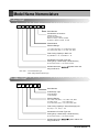
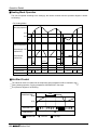
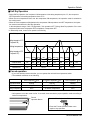
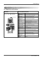
Model Name Nomenclature
Indoor Unit
CRN
N
07
6
SR
A
0
Serial Number
Combinations of functions
A: Basic Function
Art Cool Type Panel Color
B: Blue, C: Cherry, D: Wood, M: Metal
N: Walnut, R: Mirror, W: White, G: Gold
Chassis Name
Electrical Ratings
1: 1ø, 100V~115V, 60Hz, 2: 1ø, 220V~240V, 60Hz
6: 1ø, 220V~240V, 50Hz, 7: 1ø, 100V~115V, 50Hz
Total Cooling Capacity in Btu/h unit
Ex) 5,000 Btu/h ➞ ‘05’ , 18,000 Btu/h ➞ ‘18’
Combination of Inverter Type and
Cooling Only or Heat Pump or Heat Recovery
N: AC Inverter and H/P, V: AC Inverter and C/O
Indicates that this is
using the R-407C.
System indoor unit
Note: Suffix - Look: Wall Mounted Type
- Panel: Ceiling Mounted Cassette Type
Outdoor Unit
CRU
N
100
8
T
0
Serial Number
Air Discharge Type
S: Side discharge
T: Top discharge
Electrical Ratings
8: 3ø, 380V~415V, 50Hz, 9: 3ø, 380V~415V, 60Hz
A: 3ø 220V, 50Hz,
B: 3ø, 220V, 60Hz
C: 3ø, 440V~460V, 50Hz, D: 3ø, 440V~460V, 60Hz
Total Cooling Capacity in Horse Power(Hp) unit
Ex) 4.5 Hp ➞ ‘45’ , 10 Hp ➞ ‘100’
Combination of Inverter Type and
Cooling Only or Heat Pump or Heat Recovery
N: AC Inverter and H/P, V: AC Inverter and C/O
Indicates that this is
using the R-407C.
System outdoor unit
Service Manual 3
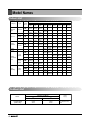
Model Names
Indoor Unit
Category
Type
Chassis
Name
SR
Wall
Mounted
Type
General
ST
Art Cool
2.6
(9,000)
3.5
(12,000)
CRNN
076SRA0
CRNN
096SRA0
CRNN
126SRA0
-
-
-
-
-
-
-
-
CRNN
186STA0
-
-
-
-
-
CRNN
076SU*0
7.0
(24,000)
8.2
(28,000)
10.6
(36,000)
12.3
(42,000)
-
-
-
-
-
-
CRNN
096SP*0
CRNN
126SP*0
-
-
-
-
-
-
-
-
-
-
-
-
-
-
-
-
Art
Cool
SP
-
Wide
SV
-
-
CRNN
126SV*0
TC
CRNN
076TCA0
CRNN
096TCA0
CRNN
126TCA0
-
TE
-
-
CRNN
126TEA0
CRNN
186TEA0
-
-
-
-
CRNN
286TDA0
CRNN
366TDA0
CRNN
426TDA0
CRNN
186SV*0
-
TD
-
-
-
-
CRNN
246TDA0
CRNN
486TDA0
VB
-
-
-
CRNN
186VBA0
CRNN
246VBA0
-
-
-
-
CRNN
246BHA0
-
-
-
-
BH
-
-
-
CRNN
186BHA0
BG
-
-
-
-
-
CRNN
286BGA0
CRNN
366BGA0
CRNN
426BGA0
-
BE
-
-
-
-
-
-
-
-
CRNN
486BEA0
BN
CRNN
076BNG0
-
-
-
-
-
-
-
-
BJ
-
CRNN
096BJG0
CRNN
126BJG0
-
-
-
-
-
-
CAA
CRNN
076CAA0
-
-
-
-
-
-
-
-
CRNN
096CBA0
CRNN
126CBA0
-
-
-
-
-
-
High
Static
Low
Static
With
Case
14.1
(48,000)
CRNN
126SU*0
SU
Convertible
Ceiling
Concealed
Duct
5.3
(18,000)
CRNN
096SU*0
4 Way
Ceiling
& Floor
Floor
Standing
2.1
(7,000)
Mirror
1 Way
Ceiling
Cassette
Model Name
Capacity, kW(Btu/h)
CBA
CRNN
186CCA0
CCA
CRNN
246CDA0
CDA
Outdoor Unit
Model name
Capacity, Hp(Btu/h)
Series
Inverter Series
(Heat Pump)
4
4.5
(44,000)
10
(95,500)
CRUN
458S0
CRUN
1008T0
Power
Supply
3ø, 4W,380V~415V,
50Hz
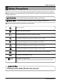
Safety Precautions
Safety Precautions
To prevent indury to the user or other people and property damage the following instructions must be followed.
■ Incorrect operation due to ignoring instruction will cause harm or damage. The seriousness is classified by the
following indications.
This symbol indicates the possibility of death or serious injury.
This symbol indicates the possibility of injury or damage to properties only.
■ Meanings of symbols used in this manual are as shown below.
Be sure not to do.
Be sure to follow the instruction.
This symbol indicates a part which must be grounded.
This symbol indicates that caution should be taken with rotating parts.
(This symbol is displayed on the main unit label.) <Color: Tellow>
This symbol indicates that the main switch must be turned off before service.
(This symbol is displayed on the main unit label.) <Color: Blue>
This symbol alerts you to the risk of electric shock.
(This symbol is displayed on the main unit label.) <Color: Yellow>
This symbol alerts you to the risk of hot surface.
(This symbol is displayed on the main unit label.) <Color: Yellow>
This symbol alerts you to hazards that could cause harmto the air conditioner.
NOTICE
ELV
This symbol indicates special notes.
Pay attention to electric shock.
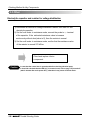
And at servicing, please shut down the power supply for both of Indoor and Outdoor
Unit.
Carefully read the labels affixed to the main unit.
Service Manual 5
Safety Precautions
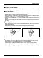
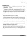
Cautions before installation
Use the specified cables for wiring. Make the
connections securely so that the outside force
of the cable is not applied to the terminals.
Always use accessories specified by LG
Electronics.
- Inadequate connection and fastening may generate heat and cause a fire.
- Ask an authorized technician to install the
accessories. Improper installation by the user
may result in water leakage, electric shock, or
fire.
Never repair the unit. If the air conditioner
must be repaired, consult the dealer.
- If the unit is repaired improperly, water leakage,
electric shock, or fire may result.
If refrigerant gas leaks during service work,
ventilate the room.
- If the refrigerant gas comes into contact with a
flame, poisonous gases will be released.
Securely install the cover of control box and
the panel.
- If the cover and panel are not installed properly,
dust or water may enter the outdoor unit and fire
or electric shock may result.
Do not touch the heat exchanger fins.
- Improper handling may result in injury.
Have all electric work done by a licensed
electrician according to "Electric Facility
Engineering Standard" and "Interior Wire
Regulations" and the instructions given in
this manual and always use a special circuit.
- If the power source capacity is inadequate or
electric work is performed improperly, electric
shock and fire may result.
When installing and moving the air conditioner to another site, do not charge it with a
refrigerant different from the refrigerant
(R407C) specified on the unit.
- If a different refrigerant or air is mixed with the
original refrigerant, the refrigerant cycle may
malfunction and the unit may be damaged.
If the air conditioner is installed in a small
room, measures must be taken to prevent the
refrigerant concentration from exceeding the
safety limit when the refrigerant leaks.
When moving and reinstalling the air conditioner, consult the dealer or an authorized
technician.
- Consult the dealer regarding the appropriate
measures to prevent the safety limit from being
exceeded. Should the refrigerant leak and cause
the safety limit to be exceeded, hazards due to
lack of oxygen in the room could result.
- If the air conditioner is installed improperly, water
leakage, electric shock, or fire may result.
6
Indoor Unit
Safety Precautions
After completing service work, make sure
that refrigerant gas is not leaking.
- If the refrigerant gas leaks and is exposed to a
fan heater, stove, oven, or other heat source, it
may generate noxious gases.
Do not install the unit where combustible gas
may leak.
- If the gas leaks and accumulates around the
unit, an explosion may result.
Do not use the air conditioner in special environments.
- Oil, steam, sulfuric smoke, etc. can significantly
reduce the performance of the air conditioner or
damage its parts.
Do not reconstruct or change the settings of
the protection devices.
- If the pressure switch, thermal switch, or other
protection device is shorted and operated
forcibly, or parts other than those specified by
LG Electronics are used, fire or explosion may
result.
Do not use the air conditioner where food,
pets, plants, precision instruments, or artwork are kept.
- The quality of the food, etc. may deteriorate.
Do not install the unit on a structure that may
cause leakage.
- When the room humidity exceeds 80% or when
the drain pipe is clogged, condensation may drip
from the indoor unit. Perform collective drainage
work together with the outdoor unit, as required.
Take measures to prevent children from
touching the unit.
- Injuries such as cuts could occur if a child
touches the surface of the fins on the heat
exchanger.
Cautions for electrical work and movement
Ground the unit.
- Do not connect the ground wire to gas or water
pipes, lightning rods, or telephone ground lines.
Improper grounding may result in electric shock.
Use power cables of sufficient current carrying capacity and rating.
- Cables that are too small may leak, generate
heat, and cause a fire.
Install the power cable so that tension is not
applied to the cable.
- Tension may cause the cable to break and generate heat and cause a fire.
Use only a circuit breaker and fuse of the
specified capacity.
- A fuse or circuit breaker of a larger capacity or a
steel or copper wire may result in a general unit
failure or fire.
Service Manual 7
Safety Precautions
Do not wash the air conditioner units.
- Washing them may cause an electric shock.
Be careful that the installation base is not
damaged by long use.
- If the damage is left uncorrected, the unit may
fall and cause personal injury or property
damage.
Safely dispose of the packing materials.
- Packing materials, such as nails and other metal or wooden parts, may cause stabs or other injuries.
- Tear apart and throw away plastic packaging bags so that children will not play with them. If children
play with a plastic bag which was not torn apart, they face the risk of suffocation.
Cautions before the test run
Turn on the power at least 12 hours before starting operation.
- Starting operation immediately after turning on the main power switch can result in severe damage to
internal parts. Keep the power switch turned on during the operational season.
Do not touch the switches with wet fingers.
- Touching a switch with wet fingers can cause an electric shock.
Do not touch the refrigerant pipes during and immediately after operation.
- During and immediately after operation, the refrigerant pipes may be hot or cold, depending on the
condition of the refrigerant flowing through the refrigerant piping, compressor, and other refrigerant
cycle parts. Your hands may suffer burns or frost-bite if you touch the refrigerant pipes.
Do not operate the air conditioner with the panels and guards removed.
- Rotating, hot, or high-voltage parts can cause injuries.
Do not turn off the power immediately after stopping operation.
- Always wait at least five minutes before turning off the power. Otherwise, water leakage and trouble
may occur.
8
Indoor Unit
Indoor Unit
Indoor Units
Service Manual 9
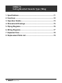
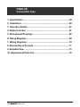
CRNN-TC
Ceiling Mounted Cassette Type (1Way)
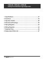
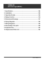
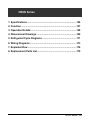
1. Specifications .............................................................................11
2. Functions ....................................................................................12
3. Operation Details........................................................................13
4. Dimensional Drawings ...............................................................15
5. Piping Diagrams .........................................................................16
6. Wiring Diagrams .........................................................................17
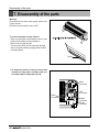
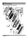
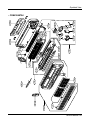
7. Exploded View ............................................................................18
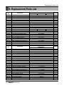
8. Replacement Parts List..............................................................19
10
Indoor Unit
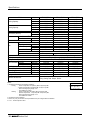
Specifications
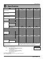
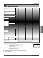
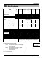
1. Specifications
CRNN076TCA0
CRNN096TCA0
CRNN126TCA0
2,100
2,600
3,500
1,806
2,235
3,009
Cooling Capacity
7,165
8,871
11,942
2,363
2,925
3,938
2,031
2,515
3,385
Heating Capacity
8,061
9,980
13,435
Galvanized Steel Plate Galvanized Steel Plate Galvanized Steel Plate
Casing
860*390*180
860*390*180
860*390*180
mm
Dimensions (W*H*D)
33.8*15.3*7.0
33.8*15.3*7.0
33.8*15.3*7.0
inch
2 x 12 x 18
2 x 12 x 21
2 x 12 x 21
Coil
Rows x Columns x FPI
2
0.184
0.184
0.184
Face Area
m
1.0
1.0
1.5
Moisture removal
l/h.
Cross Flow Fan
Cross Flow Fan
Cross Flow Fan
Type
14 x 1
14 x 1
14 x 1
Motor Output x Number
W
Fan
6/5/4
7/6/5
10/9/8
cmm
Air Flow Rate(H/M/L)
225/197/168
246/216/195
353/317/283
cfm
Direct
Direct
Direct
Drive
Phase Control
Phase Control
Phase Control
Speed Control
Microprocessor, Thermostat for cooling and heating
Temperature Control
Foamed polystyrene
Foamed polystyrene
Foamed polystyrene
Sound Absorbing Thermal Insulation Material
Fuse, Thermal Fuse for Fan Motor Fuse, Thermal Fuse for Fan Motor Fuse, Thermal Fuse for Fan Motor
Safety Device
6.35 (1/4)
6.35 (1/4)
6.35 (1/4)
Liquid Side
mm(inch)
12.7 (1/2)
12.7 (1/2)
12.7 (1/2)
Pipe Connections Gas Side
mm(inch)
25
25
25
Drain Pipe(Internal Dia.)
mm
17(37.5)
17(37.5)
17(37.5)
Net Weight
kg(lbs)
35/32/29
37/34/31
39/36/35
Noise Level (Sound Press,1.5m, H/M/L)
dB±3
1,220~240,50
1,220~240,50
1,220~240,50
Power Supply
Ø,V,Hz
12:3*2.5
12:3*2.5
12:3*2.5
Power Cable
AWG#:P*mm2
L.E.V
L.E.V
L.E.V
Refrigerant Control
White
White
White
Panel Color
1050*480*30
1050*480*30
1050*480*30
Decoration Panel Dimensions (W*H*D)
mm
41.3*18.9*1.2
41.3*18.9*1.2
41.3*18.9*1.2
inch
Model
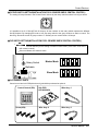
Standard Accessories
Unit
W
kcal/h
Btu/h
W
kcal/h
Btu/h
Owner Manual, Installation Manual, Paper Pattern for Installation, Drain Hose, Clamp
Metal, Insulation for Fitting, Sealing Pads, Clamps, Screws, Washers, Positioning Jig
for Installation, Insulation for Hanger Bracket, Air Outlet Blocking Pad.
Notes:1. Capacities are based on the following conditions:
Cooling:
- Indoor Temperature 27°C(80.6°F) DB /19°C(66.2°F) WB
- Outdoor Temperature 35°C(95°F) DB /24°C(75.2°F) WB
- Interconnecting Piping Length 7.5m
- Level Difference of Zero.
Heating:
- Indoor Temperature 20°C(68°F) DB / 15°C(59°F) WB
- Outdoor Temperature 7°C(44.6°F) DB / 6°C(42.8°F) WB
- Interconnecting Piping Length 7.5 m
- Level Difference of Zero.
2. Capacities are Net Capacities.
3. Due to our policy of innovation some specifications may be changed without notification.
4. L.E.V. : Linear Expansion Valve
Conversion Formula
kcal/h = kW x 860
Btu/h = kW x 3414
cfm = m3/min x 35.3
Service Manual 11
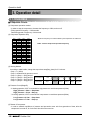
Functions
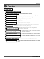
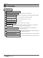
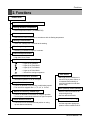
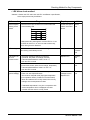
2. Functions
Indoor Unit
Operation ON/OFF by Remote controller
Sensing the Room Temperature
Room temperature control
Starting Current Control
• Room temperature sensor. (Thermistor)
• Maintains the room temperature in accordance with the Setting temperature
• Indoor fan is delayed for 5 seconds at the starting.
Time Delay Safety Control
• Restarting is inhibited for approx. 3 minutes.
Indoor Fan Speed Control
• Jet, High, Med, Low
Soft Dry Operation Mode
• Intermittent operation of fan at low speed.
Airflow Direction Control
• The louver can be set at swing up and down automatically.
Auto Restart
• Although the air-conditioner is turned off by a power failure, it is restarted automatically previous operation mode after power supply.
Deice (defrost) control (Heating)
• Both the indoor and outdoor fan stops during defrosting.
• Hot start after defrost ends.
Hot-start Control (Heating)
• The indoor fan does not rotate until the evaporator piping temperature will be reached at 25°C.
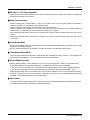
Compact and light design
• To install a unit is very convenient because of smaller
size than textile.
Low noise
12
• The most advanced low-noise design.
• The adoption of turbo fan and round type heat exchanger give the quietest operation.
Long life filter
• Long life wrinkle(type) and washable and anti-bacteria
filter is adopted.
High head Drain pump
• Built-in drain pump automatically drains water.
• A standard drain-head height of up to 700mm is possible.
High-Ceiling corresponding Function
• According to the height of ceiling, the RPM of indoor fan
motor is selected to increase air reaching distance.
Central Control(Optional)
• It is operating individually or totally by central control function.
Indoor Unit
Operation Details
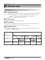
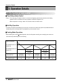
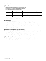
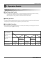
3. Operation Details
(1) The function of main control
■ Time Delay Safety Control
• 5sec
Vertical louvers are delayed for 5 secs to be opened to prevent the frictional sound between louver and air
flow.
• 30sec
The 4-way valve is ceased for 30sec. to prevent abnormal noise when the Heating operation is OFF or
switched to the other operation mode while compress is off.
While compressor is running, it takes 3~5 seconds to switch.
■ Auto Swing Control
• This function is to swing the louver up and down automatically.
■ Air-Filter Checking Control
• 'Filter' sign will appear on the remote controller display and main body display when an air-filter is polluted. Then
clean the air-filter referring to Owners Manual.
■ Soft-Dry Operation
• The indoor fan speed is automatically set to the low, and fan speed control is not available because of already being
set to the best speed for Dry Operation by microcontroller control.
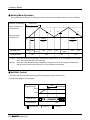
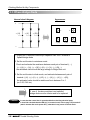
■ Cooling Mode Operation
• When selecting the Cooling( ) Mode Operation, the unit will operate according to the setting by the remote controller and the operation diagram is as follows.
Intake Air Temperature
SET TEMPERATURE +0.5°C
(COMP. ON)
SET TEMPERATURE
SET TEMPERATURE -0.5°C
(COMP. OFF)
INDOOR FAN
COMPRESSOR
More than
More than
3 minutes
3 minutes
Selected
fan speed
Low
Selected
fan speed
Low
Selected
fan speed
ON
OFF
ON
OFF
ON
Service Manual 13
Operation Details
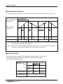
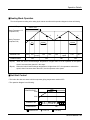
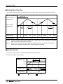
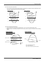
■ Heating Mode Operation
The unit will operate according to the setting by the remote controller and the operation diagram is shown as follows.
Intake Air Temperature.
minimum 3min
Setting Temperature .+3°C
(Compressor OFF)
A
Setting Temperature
(Compressor ON)
INDOOR FAN
1min
(Hot Start)
OFF
COMPRESSOR
Low
Selected
Fan Speed
A
B
minimum
minimum
minimum
10sec.
1min.
10sec.
Low
Selecting fan Low
speed
Low
ON
OFF
OFF
ON
OFF
OFF
A point; While the indoor Heat-Exchanger temperature is higher than 40°C fan operates at low speed,
when it becomes lower than 40˚C fan stops.
B point; When the indoor Heat-Exchanger temperature is higher than 42°C, fan operates at selected fan
speed, when it becomes lower than 39°C, the fan operates at low speed.
■ Hot-Start Control
• The indoor fan sdoes not rotate until the evaporator piping temperature reaches to 25°C.
• If the evaporator piping temperature drops below 22°C, indoor fan stops again.
• The operation diagram is as follows.
PIPING
TEMPERATURE
25°C
1min
22°C
INDOOR FAN
COMPRESSOR
14
Indoor Unit
OFF
LOW
ON
Selected
fan speed
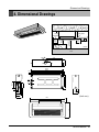
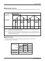
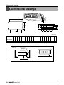
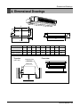
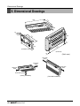
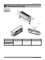
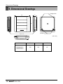
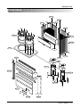
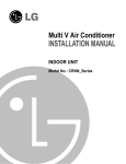
Dimensional Drawings
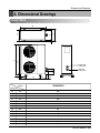
20 or more
4. Dimensional Drawings
Ceiling Board
50 or
more
30 or less
Above 250
330 or less
50 or
more
100
or more
Ceiling
Ceiling Board
Unit:cm
Floor
Ø80
430
390
328.4
42.7
155
164
194.4
30.8
50
91.6
16.7
7
931.6
893.4
860
846
180
130
Ø55
37
91.6
97.7
116.3
180
141.8
180
(Unit: mm)
1050
694.5
480
Service Manual 15
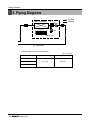
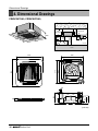
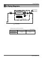
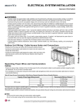
Piping Diarams
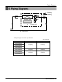
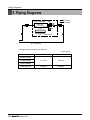
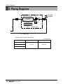
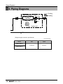
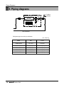
5. Piping Diagrams
Heat Exchanger
LEV
:Cooling
:Heating
Filter
C.F.F.
Filter
lndoor unit
: Thermistor
Refrigerant pipe connection port diameter
[unit: mm(inch)]
Model
Gas
Liquid
12.7(1/2)
6.35(1/4)
CRNN076TCA0
CRNN096TCA0
CRNN126TCA0
16
Indoor Unit
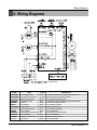
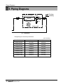
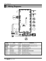
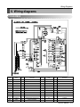
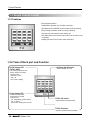
Wiring Diagrams
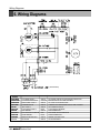
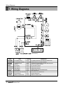
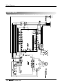
6. Wiring Diagrams
1(L) 2(N)
3
4
(Transmission)
CONNECTOR
NUMBER
CN-POWER
CN-MOTOR2
CN-D/PUMP
CN-COMM
CN-DISP1
CN-LEV
CN-STEP/M1
CN-FLOAT
CN-PIPE
CN-PIPE/O
CN-ROOM
CN-REMO
CN-AIRC
SPEC
COLOR
AC POWER SUPPLY
AC FAN MOTOR OUTPUT
DRAIN PUMP OUTPUT
COMMUNICATION
DISPLAY
LEV OUTPUT
STEP MOTOR
FLOAT SWITCH INPUT
PIPE SENSOR
DISCHARGE PIPE SENSOR
ROOM SENSOR
REMOTE CONTROLLER
AIR CLEAN
WHITE
YELLOW
WHITE
WHITE
WHITE
WHITE
WHITE
BLUE
WHITE
RED
BLUE
WHITE
WHITE
DESCRIPTION
AC POWER LINE INPUT FOR INDOOR CONTROLLER
MOTOR OUTPUT OF PHASE CONTROL
AC OUTPUT FOR DRAIN PUMP
COMMUNICATION BETWEEN INDOOR AND OUTDOOR
DISPLAY OF INDOOR STATUS
LEV CONTROL OUTPUT
STEP MOTOR OUTPUT
FLOAT SWITCH SENSING
PIPE THERMISTOR
DISCHARGE PIPE THERMISTOR
ROOM THERMISTOR
REMOTE CONTROL LINE
AIR CLEAN SIGNAL
Service Manual 17
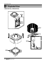
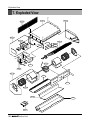
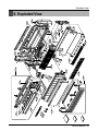
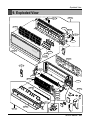
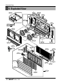
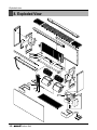
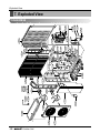
18
Indoor Unit
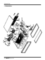
135802
137211
352150-1
268712
146811
435310
152312
330870
346810
263230-1
352116
352115
359011
263230-2
158580
266012
263230-3
352150-2
W0CZZ
267110
268714
354210
130911
Basic
249951
Exploded View
7. Exploded View
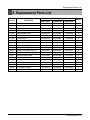
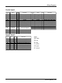
Replacement Parts List
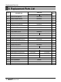
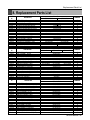
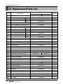
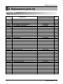
8. Replacement Parts List
PART No.
LOCATION No.
REMARK
DESCRIPTION
CRNN076TCA0
CRNN096TCA0
CRNN126TCA0
130911
CABINET ASSEMBLY,INDOOR
3091A10024A
R
146811
MOTOR ASSEMBLY,STEP
4681AR2727G
R
152312
FILTER ASSEMBLY,AIR CLEANER
5231A10003A
R
158580
PUMP ASSEMBLY,WATER
5859A10001A
R
137211
PANEL ASSEMBLY,FRONT(INDOOR)
3721A10023Y
R
249951
CONTROL BOX ASSEMBLY,INDOOR
4995A10024Q
4995A10024R
4995A10024X
R
263230-1
THERMISTOR ASSEMBLY(ROOM)
6323AQ3214P
R
263230-2
THERMISTOR ASSEMBLY(PIPE-IN)
6323AQ3226E
R
263230-3
THERMISTOR ASSEMBLY(PIPE-OUT)
6323AQ3226V
R
266012
SWITCH ASSEMBLY,FLOAT
6601A20001E
R
267110
REMOTE CONTROLLER ASSEMBLY
6711A10002A
R
268712
PWB(PCB) ASSEMBLY,DISPLAY
6871A20096B
R
268714
PWB(PCB) ASSEMBLY,MAIN
330870
DRAIN PAN ASSEMBLY
3087A10005A
R
346810
MOTOR ASSEMBLY,AC
4681A20003V
R
352115
TUBE ASSEMBLY,EVAPORATOR IN
5211A10303A
R
352116
TUBE ASSEMBLY,EVAPORATOR OUT
5211A20230D
R
354210
EVAPORATOR ASSEMBLY,FIRST
359011
FAN ASSY,CROSS FLOW
5901AR2441A
R
435310
GRILLE ASSEMBLY,INLET
3531A10062D
R
W0CZZ
CAPACITOR,DRAWING
3H00671E
R
6871A10089A
5421A10011B
6871A10089B
5421A10011A
6871A10089C
5421A10011A
R
R
352150-1
DRAIN TUBE ASSEMBLY
5251AP2984A
R
352150-2
DRAIN ASSEMBLY,TUBE
5251A20001A
R
Service Manual 19
CRNN-TE / CRNN-TD
Ceiling Mounted Cassette Type (4Way)
1. Specifications .............................................................................21
2. Functions ....................................................................................23
3. Operation Details........................................................................24
4. Dimensional Drawings ...............................................................26
5. Piping Diagrams .........................................................................28
6. Wiring Diagrams .........................................................................29
7. Exploded View ............................................................................30
8. Replacement Parts List..............................................................34
20
Indoor Unit
Specifications
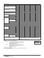
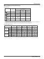
1. Specifications
Model
Unit
W
kcal/h
Btu/h
Kw
kcal/h
Btu/h
Owner Manual, Installation Manual, Paper Pattern for Installation, Drain
Hose, Clamp Metal, Washer fixing Plate, Sealing Pads, Clamps, Screws,
Washer for Hanging Bracket, Insulation for Fitting
Notes:1. Capacities are based on the following conditions:
Cooling:
- Indoor Temperature 27°C(80.6°F) DB /19°C(66.2°F) WB
- Outdoor Temperature 35°C(95°F) DB /24°C(75.2°F) WB
- Interconnecting Piping Length 7.5m
- Level Difference of Zero.
Heating:
- Indoor Temperature 20°C(68°F) DB / 15°C(59°F) WB
- Outdoor Temperature 7°C(44.6°F) DB / 6°C(42.8°F) WB
- Interconnecting Piping Length 7.5 m
- Level Difference of Zero.
2. Capacities are Net Capacities.
3. Due to our policy of innovation some specifications may be changed without notification.
4. L.E.V. : Linear Expansion Valve
Conversion Formula
kcal/h = kW x 860
Btu/h = kW x 3414
cfm = m3/min x 35.3
Service Manual 21
Indoor Unit
Standard Accessories
Cassette-4way
CRNN126TEA0
CRNN186TEA0
CRNN246TDA0
3,500
5,300
7,000
Cooling Capacity
3,009
4,557
6,019
11,942
18,084
23,885
3,938
5,963
7,875
Heating Capacity
3,385
5,127
6,771
13,435
20,345
26,870
Casing
Galvanized Steel Plate Galvanized Steel Plate Galvanized Steel Plate
mm
570*570*269
570*570*269
840*840*288
Dimensions (W*H*D)
inch
22.4*22.4*10.5
22.4*22.4*10.5
33.0*33.0*11.3
Coil
Rows x Columns x FPI
2*11*19
2*11*21
2*12*21
Face Area
m2
0.274
0.274
2*0.22
Moisture removal
l/h.
1.0
1.9
4.02
Type
Turbo Fan
Turbo Fan
Turbo Fan
Motor Output x Number
W
20
22.4
52.5
Fan
Air Flow Rate(H/M/L)
cmm
11 / 10 / 9
13 / 12 / 10
19 / 17 / 15
cfm
353/317/283
459/423/353
670/600/530
Drive
Direct
Direct
Direct
Speed Control
Phase control
Phase control
Phase control
Temperature Control
Microprocessor, Thermostat for cooling and heating
Sound Absorbing Thermal Insulation Material
Foamed polystyrene
Foamed polystyrene
Foamed polystyrene
Safety Device
Fuse, Thermal Fuse for Fan Motor Fuse, Thermal Fuse for Fan Motor Fuse, Thermal Fuse for Fan Motor
Liquid Side
mm(inch)
6.35 (1/4)
9.52 (3/8)
9.52 (3/8)
Pipe Connections Gas Side
mm(inch)
12.7 (1/2)
15.88 (5/8)
15.88 (5/8)
Drain Pipe(Internal Dia.)
mm
25
25
25
Net Weight
kg(lbs)
19(41.9)
19(41.9)
32(70.5)
Noise Level (Sound Press,1.5m, H/M/L)
dB±3
38 / 35 / 32
41 / 39 / 37
36 / 34 / 32
Power Supply
Ø,V,Hz
1,220~240,50
1,220~240,50
1,220~240,50
Power Cable
AWG#:P*mm2
12:3*2.5
12:3*2.5
12:3*2.5
Refrigerant Control
L.E.V
L.E.V
L.E.V
Panel Color
White
White
White
Decoration Panel Dimensions (W*H*D)
mm
670*670*30
670*670*30
950*950*30
inch
26.4*26.4*1.2
26.4*26.4*1.2
37.4*37.4*1.2
Specifications
Model
Cooling Capacity
Heating Capacity
Unit
W
kcal/h
Btu/h
W
kcal/h
Btu/h
Casing
Dimensions (W*H*D)
Coil
Rows x Columns x FPI
Face Area
Moisture removal
Fan
Type
Motor Output x Number
Air Flow Rate(H/M/L)
mm
inch
m2
l/h.
W
cmm
cfm
Drive
Speed control
Temperature Control
Sound Absorbing Thermal Insulation Material
Safety Device
Liquid Side
mm(inch)
Pipe Connections Gas Side
mm(inch)
Drain Pipe(Internal Dia.)
mm
Net Weight
kg(lbs)
Noise Level (Sound Press,1.5m, H/M/L) dBA±3
Power Supply
Ø,V,Hz
Power Cable
AWG#:P*mm2
Refrigerant Control
Panel Color
Decoration Panel Dimensions (W*H*D)
mm
inch
Standard Accessories
CRNN286TDA0
8,200
7,052
27,995
9,225
7,934
31,494
CRNN366TDA0 CRNN426TDA0 CRNN486TDA0
10,600
12,300
14,100
9,116
10,578
12,126
36,168
41,992
48,137
11,925
13,838
15,863
10,253
11,040
13,156
40,689
43,829
54,156
Galvanized Steel Plate
840*840*288
840*840*288
840*840*288
840*840*288
33.0*33.0*11.3
33.0*33.0*11.3
33.0*33.0*11.3
33.0*33.0*11.3
2*11*21
2*11*21
2*11*21
2*11*21
2*0.26
2*0.26
2*0.26
2*0.26
4.2
5.0
5.2
5.5
Turbo Fan
Turbo Fan
Turbo Fan
Turbo Fan
52.5
52.5
52.5
52.5
21 / 19 / 17
25 / 23 / 21
27 / 25 / 22
30 / 28 / 26
741/670/600
883/812/742
953/883/777
1,059/988/918
Direct
Phase control
Microprocessor, Thermostat for cooling and heating
Foamed polystyrene
Fuse, Thermal Fuse for Fan Motor
9.52 (3/8)
9.52 (3/8)
9.52 (3/8)
9.52 (3/8)
15.88 (5/8)
19.05(3/4)
19.05(3/4)
19.05(3/4)
25
25
25
25
32(70.5)
32(70.5)
32(70.5)
32(70.5)
42/40/38
43/41/39
44/42/40
45/43/41
1,220~240,50
1,220~240,50
1,220~240,50
1,220~240,50
12:3*2.5
12:3*2.5
12:3*2.5
12:3*2.5
L.E.V
L.E.V
L.E.V
L.E.V
White
White
White
White
950*950*30
950*950*30
950*950*30
950*950*30
37.4*37.4*1.2
37.4*37.4*1.2
37.4*37.4*1.2
37.4*37.4*1.2
Owner Manual, Installation Manual, Paper Pattern for Installation, Drain Hose,
Clamp Metal, Washer fixing Plate, Sealing Pads, Clamps, Screws, Washer for
Hanging Bracket, Insulation for Fitting
Notes:1. Capacities are based on the following conditions:
Cooling:
- Indoor Temperature 27°C(80.6°F) DB /19°C(66.2°F) WB
- Outdoor Temperature 35°C(95°F) DB /24°C(75.2°F) WB
- Interconnecting Piping Length 7.5m
- Level Difference of Zero.
Heating:
- Indoor Temperature 20°C(68°F) DB / 15°C(59°F) WB
- Outdoor Temperature 7°C(44.6°F) DB / 6°C(42.8°F) WB
- Interconnecting Piping Length 7.5 m
- Level Difference of Zero.
2. Capacities are Net Capacities.
3. Due to our policy of innovation some specifications may be changed without notification.
4. L.E.V. : Linear Expansion Valve
22
Indoor Unit
Conversion Formula
kcal/h = kW x 860
Btu/h = kW x 3414
cfm = m3/min x 35.3
Functions
2. Functions
Indoor Unit
Operation ON/OFF by Remote controller
Sensing the Room Temperature
Room temperature control
Starting Current Control
• Room temperature sensor. (Thermistor)
• Maintains the room temperature in accordance with the Setting Temperature.
• Indoor fan is delayed for 5 seconds at the starting.
Time Delay Safety Control
• Restarting is inhibited for approx. 3 minutes.
Indoor Fan Speed Control
• Jet, High, Med, Low
Soft Dry Operation Mode
• Intermittent operation of fan at low speed.
Airflow Direction Control
• The louver can be set at swing up and down automatically.
Auto Restart
• Although the air-conditioner is turned off by a power failure, it is restarted automatically previous operation mode after power supply.
Deice (defrost) control (Heating)
• Both the indoor and outdoor fan stops during defrosting.
• Hot start after defrost ends.
Hot-start Control (Heating)
• The indoor fan does not rotate until the evaporator piping temperature will be reached at 25°C.
Compact and light design
• To install a unit is very convenient because of smaller
size than textile.
Low noise
• The most advanced low-noise design.
• The adoption of turbo fan and round type heat exchanger give the quietest operation.
Long life filter
• Long life wrinkle(type) and washable and anti-bacteria
filter is adopted.
High head Drain pump
• Built-in drain pump automatically drains water.
• A standard drain-head height of up to 700mm is possible.
High-Ceiling corresponding Function
• According to the height of ceiling, the RPM of indoor fan
motor is selected to increase air reaching distance.
Central Control(Optional)
• It is operating individually or totally by central control function.
Service Manual 23
Operation detail
3. Operation detail
(1) The function of main control
■ Time Delay Safety Control
• 5 sec... Vertical air flow direction control louvers open in 5 seconds to prevent noise between louvers and wind.
• 5 sec... The 4-way valve is ceased for 5 sec. to prevent the refrigerant-gas abnormal noise when the Heating
operation is OFF or switched to the other operation mode when compress is off.
While compressor is running, it takes 3~5 seconds to switch.
■ Auto Swing Control
• This function is to swing the louver up and down automatically.
■ Soft-Dry Operation
• The indoor fan speed is automatically set to the low, so the shift of the indoor fan speed is impossible because of
already being set to the best speed for Dry Operation by microcontroller control.
■ Cooling Mode Operation
• When selecting the Cooling( ) Mode Operation, the unit will operate according to the setting by the remote controller and the operation diagram is as following
Intake Air Temperature
COMP. ON
(SET TEMPERATURE +0.5°C)
COMP. OFF
(SET TEMPERATURE -0.5°C)
INDOOR FAN
24
Indoor Unit
Selecting
fan speed
More than
More than
3 minutes
3 minutes
Low
Selecting
fan speed
Low
Selecting
fan speed
Operation detail
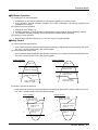
■ Heating Mode Operation
The unit will operate according to the setting by the remote controller and the operation diagram is shown as following.
Intake Air temperature
minimum 3min
Setting Temperature .+3°C
(Compressor OFF)
A
Setting Temperature
(Compressor ON)
INDOOR FAN
1min
Hot Start
Low
Selecting
Fan Speed
B
A
minimum
minimum
minimum
10sec.
1min.
10sec.
Low
OFF
Low
Selecting fan
speed
Low
OFF
• A point;
While the indoor Heat-Exchanger temperature is higher than 40°C fan operates at low speed,
when it becomes lower than 40˚C fan stops.
• B point;
When the indoor Heat-Exchanger temperature is higher than 31°C, fan operates at selected fan
speed, when it becomes lower than 31°C, the fan operates at low speed for 10sec, after 10sec, it
operates at selected fan speed.
■ Hot-start Control
The indoor fan does no rotate until the evaporator piping temperature will be reached to 25°C.
The operation diagram is as following.
PIPING
TEMPERATURE
25°C
1min
22°C
INDOOR FAN
COMPRESSOR
OFF
LOW
Selected Fan
ON
Service Manual 25
Dimensional Drawings
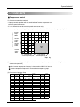
4. Dimensional Drawings
30 or more
CRNN126TEA0, CRNN186TEA0,
Ceiling Board
30 or less
Ceiling
Ceiling Board
50 or
more
Above 250
330 or less
50 or
more
670
100
or more
269
670
Unit:cm
Floor
570
670
CLOSE
OPEN
OPEN
521
670
570
450
CLOSE
30
40
190.5
52
160
110
90
90
120.4
55
269
110
(unit:mm)
26
Indoor Unit
Dimensional Drawings
Ceiling
Ceiling Board
50 or
more
950
950
50 or
more
Above 250
330 or less
100
or more
290
Ceiling Board
30 or less
30 or more
CRNN246TDA0, CRNN286TDA0, CRNN366TDA0
CRNN426TDA0, CRNN486TDA0
Unit:cm
Floor
840
950
950
785
840
678
210.5
52 180
110
90
110
90
140
290
55
30
40
(unit:mm)
Service Manual 27
Piping Diagrams
5. Piping Diagrams
Heat Exchanger
:Cooling
:Heating
LEV
Filter
Turbo Fan
Filter
lndoor unit
: Thermistor
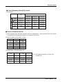
Refrigerant pipe connection port diameter
[unit: mm(inch)]
28
Model
Gas
Liquid
CRNN126TEA0
12.7(1/2)
6.35(1/4)
CRNN186TEA0
15.88(5/8)
9.52(3/8)
CRNN246TDA0
15.88(5/8)
9.52(3/8)
CRNN286TDA0
15.88(5/8)
9.52(3/8)
CRNN366TDA0
19.05(3/4)
9.52(3/8)
CRNN426TDA0
19.05(3/4)
9.52(3/8)
CRNN486TDA0
19.05(3/4)
9.52(3/8)
Indoor Unit
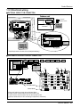
Wiring Diagrams
6. Wiring Diagrams
1(L) 2(N)
3
4
(Transmission)
CONNECTOR
NUMBER
CN-POWER
CN-MOTOR2
CN-D/PUMP
CN-COMM
CN-DISP1
CN-LEV
CN-STEP/M1
CN-FLOAT
CN-PIPE
CN-PIPE/O
CN-ROOM
CN-REMO
CN-AIRC
SPEC
COLOR
AC POWER SUPPLY
AC FAN MOTOR OUTPUT
DRAIN PUMP OUTPUT
COMMUNICATION
DISPLAY
LEV OUTPUT
STEP MOTOR
FLOAT SWITCH INPUT
PIPE SENSOR
DISCHARGE PIPE SENSOR
ROOM SENSOR
REMOTE CONTROLLER
AIR CLEAN
WHITE
YELLOW
WHITE
WHITE
WHITE
WHITE
WHITE
BLUE
WHITE
RED
BLUE
WHITE
WHITE
DESCRIPTION
AC POWER LINE INPUT FOR INDOOR CONTROLLER
MOTOR OUTPUT OF PHASE CONTROL
AC OUTPUT FOR DRAIN PUMP
COMMUNICATION BETWEEN INDOOR AND OUTDOOR
DISPLAY OF INDOOR STATUS
LEV CONTROL OUTPUT
STEP MOTOR OUTPUT
FLOAT SWITCH SENSING
PIPE THERMISTOR
DISCHARGE PIPE THERMISTOR
ROOM THERMISTOR
REMOTE CONTROL LINE
AIR CLEAN SIGNAL
Service Manual 29
Explodede View
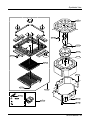
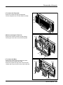
7. Exploded View
CRNN126TEA0, CRNN186TEA0
249951
268714
263230-1
354211
352115
352118
263230-2
263230-3
158591
266012
330870
30
Indoor Unit
Explodede View
130411
W0CZZ
346810
359011
146811
268712
140570
152312
130911-2
135802
137211
352150-1
130911-1
267110
352150-2
Service Manual 31
Explodede View
CRNN246TDA0, CRNN286TDA0, CRNN366TDA0, CRNN426TDA0, CRNN486TDA0
249951
249951
268714
263230-3
354211-1
130411
354211-2
352114
55211G
263230-1
263230-2
352118
330870
158591
266012
32
Indoor Unit
Explodede View
130411
W0CZZ
146811
268712
346810
152312
359012
130913-2
140570
130911-2
135314
135802
137211
130911-1
352150
130913-1
267110
152510
Service Manual 33
Replacement Parts List
8. Replacement Parts List
LOCATION
NO.
130411
PART NO.
DESCRIPTION
CRNN126TEA0
REMARK
CRNN186TEA0
BASE ASSY,WELD[INDOOR]
3041A10013A
R
130911-1
CABINET ASSEMBLY,INDOOR
3091A10023C
R
130911-2
CABINET ASSEMBLY,INDOOR
3091A10023D
R
135802
DOOR
3580A20005A
R
137211
PANEL ASSY,FRONT(INDOOR)
3721A10021A
R
140570
LOCKER
4056A20001A
R
146811
MOTOR ASSY,STEP
4681AP2968D
R
152312
FILTER ASSY,AIR CLEANER
5231A10005A
R
158591
PUMP ASSEMBLY,WATER
5859A20001H
R
249951
CONTROL BOX ASSEMBLY,INDOOR
4995A10083A
4995A10083B
R
263230-1
THERMISTOR ASSEMBLY(ROOM)
6323AQ3214B
R
263230-2
THERMISTOR ASSEMBLY(PIPE-IN)
6323A30002B
R
263230-3
THERMISTOR ASSEMBLY(PIPE-OUT)
6323AQ3226R
R
266012
SWITCH ASSY,FLOAT
6601A20001F
R
267110
REMOTE CONTROLLER ASSEMBLY
6711A10002A
R
268712
PWB(PCB) ASSY,DISPLAY
6871A20096C
R
268714
PWB(PCB) ASSEMBLY,MAIN
330870
DRAIN PAN ASSEMBLY
346810
MOTOR ASSEMBLY,SINGLE
4681AC2026E
4681AC2026D
R
352115
TUBE ASSEMBLY,EVAPORATOR IN
5211A10335B
5211A10335A
R
352118
TUBE ASSEMBLY,MENIFOLD(INDOOR)
5211A20241N
5211A20241P
R
354211
EVAPORATOR ASSY,BENDING
5421A10006A
5421A10006B
R
359011
FAN,TURBO
W0CZZ
CAPACITOR,DRAWING
6871A10089D
6871A10089E
3087A10002A
R
R
5900A10004A
R
3H00660N
R
352150-1
DRAIN TUBE ASSEMBLY
5251AP2984A
R
352150-2
DRAIN ASSEMBLY,TUBE
5251A20002A
R
34
Indoor Unit
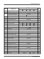
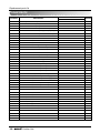
Replacement Parts List
PART NO.
LOCATION
NO.
REMARK
DESCRIPTION
CRNN246TDA0
CRNN286TDA0
CRNN366TDA0
CRNN426TDA0
CRNN486TDA0
354211-1
EVAPORATOR ASSY
5421A10016A
R
354211-2
EVAPORATOR ASSY
5421A10016B
R
TUBE ASSEMBLY, MENIFOLD (INDOOR)
5211A20251B
R
352118
TUBE ASSEMBLY, MENIFOLD (INDOOR)
5211A20251H
5211A20251G
R
352114
TUBE ASSEMBLY, DISTRIBUTOR
5211A10299A
R
55211G
TUBE ASSEMBLY, EXPANSION
5211A10298A
R
158591
PUMP ASSEMBLY, WATER
5859A20001D
R
266012
SWITCH ASSY, FLOAT
6601A20001F
R
330870
DRAIN PAN ASSY
3087A100006A
R
249951
CONTROL BOX ASSY
4995A20268X 4995A20268Y 4995A20268A 4995A20268Z 4995A10106L
R
268714
PWB(PCB) ASSY, MAIN
6871A10089F F6871A10089G
R
130411
BASE ASSY, WELD INDOOR
346810
MOTOR ASSY, INDOOR
359012
FAN,TURBO
5900A10003B
R
140570
LOCKER
4056A20001B
R
130911-1
CABINET ASSY, INDOOR
3091A10031A
R
130911-2
CABINET ASSY, INDOOR
3091A10031B
R
130913-1
CABINET ASSEMBLY, WELD
3091A10030A
R
130913-2
CABINET ASSEMBLY, WELD
3091A10030B
R
152510
DRAIN ASSY, TUBE
5251A20002B
R
352150
DRAIN TUBE ASSY
5251AP2984A
R
137211
PANEL ASSY, FRONT(INDOOR)
3721A10025A
R
135314
GRILLE INLET
3530A10062A
R
146811
MOTOR ASSY, STEP
4681A20055A
R
268712
PWB(PCB) ASSY, DISPLAY
6871A20096C
R
152312
FILTER ASSY
5231A10004A
R
135802
DOOR LOCK
3580A20005A
R
267110
WIRED REMOTE CONTROLLER
6711A10002A
R
263230-1
THERMISTOR ASSY(PIPE-IN)
6323A30002A
R
263230-2
THERMISTOR ASSY(PIPE-OUT)
6323AQ3226T
R
263230-3
THERMISTOR ASSY(ROOM)
6323A30004C
R
W0CZZ
CAPACITOR
6871A10089H 6871A10089S
6871A10089T
3041A10016A
4681A20006J
3H00660M
R
4681A20006H
2A00986D
R
R
Service Manual 35
CRNN-BH / CRNN-BG / CRNN-BE
Ceiling Concealed Duct Type (High static)
1. Specifications .............................................................................37
2. Functions ....................................................................................39
3. Operation Details........................................................................40
4. Dimensional Drawings ...............................................................42
5. Piping Diagrams .........................................................................43
6. Wiring Diagrams .........................................................................44
7. Exploded View ............................................................................45
8. Replacement Parts List..............................................................47
36
Indoor Unit
Specifications
1. Specifi cations
Model
Cooling Capacity
Heating Capacity
Unit
W
kcal/h
Btu/h
W
kcal/h
Btu/h
Casing
Dimensions (W*H*D)
Coil
Rows x Columns x FPI
Face Area
Moisture removal
Fan
Type
Motor Output x Number
Air Flow Rate(H/M/L)
mm
inch
m2
l/h.
W
cmm
cfm
Pa
External Static Pressure
Drive
Speed control
Temperature Control
Sound Absorbing Thermal Insulation Material
Safety Device
Liquid Side
mm(inch)
Pipe Connections Gas Side
mm(inch)
Drain Pipe(Internal Dia.)
mm
Net Weight
kg(lbs)
Noise Level (Sound Press,1.5m, H/M/L) dBA±3
Power Supply
Ø,V,Hz
Power Cable
AWG#:P*mm2
Refrigerant Control
Standard Accessories
CRNN186BHA0
5,300
4,557
18,084
5,963
5,127
20,345
CRNN246BHA0
CRNN286BGA0
7,000
8,200
6,019
7,052
23,885
27,995
7,875
9.255
6,771
7,933
26,870
31,494
Galvanized Steel Plate
880*260*450
880*260*450
1,180*298*450
34.6*10.2*17.7
34.6*10.2*17.7
46.4*11.7*17.7
2*10*21
3*10*21
3*12*21
0.15
0.15
0.20
2.0
2.5
3.0
Sirocco Fan
Sirocco Fan
Sirocco Fan
118
118
272
16.5 / 14.5 / 13
18 / 16.5 / 14
30 / 27 / 25
583 / 512 / 459
636 / 583 / 494
1,059 / 953 / 882
78.5
58.8
78.5
Direct
Phase control
Microprocessor, Thermostat for cooling and heating
Foamed polystyrene
Fuse, Thermal Fuse for Fan Motor
9.52 (3/8)
9.52 (3/8)
9.52 (3/8)
15.88 (5/8)
15.88 (5/8)
15.88 (5/8)
25
25
25
34(74.9)
35(77.2)
38(83.8)
36 / 34 / 32
38 / 35 / 32
40 / 38 / 36
1,220~240,50
1,220~240,50
1,220~240,50
12:3*2.5
12:3*2.5
12:3*2.5
L.E.V
L.E.V
L.E.V
Owner Manual, Installation Manual, Drain Hose, Clamp Metal, Insulation
for Fitting, Sealing Pads, Clamps, Screws
Notes:1. Capacities are based on the following conditions:
Cooling:
- Indoor Temperature 27°C(80.6°F) DB /19°C(66.2°F) WB
- Outdoor Temperature 35°C(95°F) DB /24°C(75.2°F) WB
- Interconnecting Piping Length 7.5m
- Level Difference of Zero.
Heating:
- Indoor Temperature 20°C(68°F) DB / 15°C(59°F) WB
- Outdoor Temperature 7°C(44.6°F) DB / 6°C(42.8°F) WB
- Interconnecting Piping Length 7.5 m
- Level Difference of Zero.
2. Capacities are Net Capacities.
3. Due to our policy of innovation some specifications may be changed without notification.
4. L.E.V. : Linear Expansion Valve
Conversion Formula
kcal/h = kW x 860
Btu/h = kW x 3414
cfm = m3/min x 35.3
Service Manual 37
Specifications
Model
Cooling Capacity
Heating Capacity
Unit
W
kcal/h
Btu/h
W
kcal/h
Btu/h
Casing
Dimensions (W*H*D)
Coil
Rows x Columns x FPI
Face Area
Moisture removal
Fan
Type
Motor Output x Number
Air Flow Rate(H/M/L)
mm
inch
m2
l/h.
W
cmm
cfm
Pa
External Static Pressure
Drive
Speed control
Temperature Control
Sound Absorbing Thermal Insulation Material
Safety Device
Liquid Side
mm(inch)
Pipe Connections Gas Side
mm(inch)
Drain Pipe(Internal Dia.)
mm
Net Weight
kg(lbs)
Noise Level (Sound Press,1.5m, H/M/L) dBA±3
Power Supply
Ø,V,Hz
Power Cable
AWG#:P*mm2
Refrigerant Control
Standard Accessories
CRNN366BGA0
10,600
9,116
36,188
11,925
10,255
40,712
CRNN426BGA0
CRNN486BEA0
12,300
14,100
10,578
12,126
41,992
48,137
13,837
15,885
11,900
13,661
47,410
54,231
Galvanized Steel Plate
1,180*298*450
1,230*370*680
1,230*370*680
46.4*11.7*17.7
48.4*14.6*26.8
48.4*14.6*26.8
3*12*21
3*14*17
3*14*17
0.20
0.55
0.25
3.5
5.0
6.0
Sirocco Fan
Sirocco Fan
Sirocco Fan
272
391
391
32/29/26.5
38/34/28
40/36/30
1,130/1,024/936
1,341/1,200/988
1,413/1,271/1,059
78.5
78.5
98.1
Direct
Phase control
Steps control
Microprocessor, Thermostat for cooling and heating
Foamed polystyrene
Fuse, Thermal Fuse for Fan Motor
9.52(3/8)
9.52(3/8)
9.52(3/8)
19.05(3/4)
19.05(3/4)
19.05(3/4)
25
25
25
38(83.8)
70(154.3)
70(154.3)
44/42/40
46/44/42
48/46/44
1,220~240,50
1,220~240,50
1,220~240,50
12:3*2.5
12:3*2.5
12:3*2.5
L.E.V
L.E.V
L.E.V
Owner Manual, Installation Manual, Drain Hose, Clamp Metal, Insulation for
Fitting, Sealing Pads, Clamps, Screws
Notes:1. Capacities are based on the following conditions:
Cooling:
- Indoor Temperature 27°C(80.6°F) DB /19°C(66.2°F) WB
- Outdoor Temperature 35°C(95°F) DB /24°C(75.2°F) WB
- Interconnecting Piping Length 7.5m
- Level Difference of Zero.
Heating:
- Indoor Temperature 20°C(68°F) DB / 15°C(59°F) WB
- Outdoor Temperature 7°C(44.6°F) DB / 6°C(42.8°F) WB
- Interconnecting Piping Length 7.5 m
- Level Difference of Zero.
2. Capacities are Net Capacities.
3. Due to our policy of innovation some specifications may be changed without notification.
4. L.E.V. : Linear Expansion Valve
38
Indoor Unit
Conversion Formula
kcal/h = kW x 860
Btu/h = kW x 3414
cfm = m3/min x 35.3
Functions
2. Functions
Indoor Unit
Operation ON/OFF by Remote controller
Sensing the Room Temperature
• Maintains the room temperature in accordance with the Setting Temperature.
Room temperature control
Starting Current Control
• Room temperature sensor. (Thermistor)
• Indoor fan is delayed for 5 seconds at the starting.
Time Delay Safety Control
• Restarting is inhibited for approx. 3 minutes.
Indoor Fan Speed Control
• High, Med, Low
Soft Dry Operation Mode
Auto Restart
• Intermittent operation of fan at low speed.
• Although the air-conditioner is turned off by a power failure, it is restarted automatically previous operation mode after power supply.
Deice (defrost) control (Heating)
• Both the indoor and outdoor fan stops during defrosting.
• Hot start after defrost ends.
Hot-start Control (Heating)
• The indoor fan does not rotate until the evaporator piping
temperature reaches 25°C.
High head height Drain pump
• A standard drain-head height of up to 700mm is possible.
Central Control(Optional)
• It is operating individually or totally by central control function.
Defrost(Deice) control (Heating)
Hot-start Control (Heating)
• Both the indoor and outdoor fan stops during defrosting.
• The indoor fan stops until the evaporator pipe temperature will be reached
at 28°C.
Service Manual 39
Operation Details
3. Operation Details
(1) The function of main control
■ Time Delay safety Control
• 30sec... The 4-way valve is ceased for 30sec. to prevent the refrigerant-gas abnormal noise when the Heating
operation is OFF or switched to the other operation mode while compress is off.
While compressor is running, it takes 3~5 seconds to switch to another mode.
■ Soft-Dry Operation
• The indoor fan speed is automatically set to the low, so the shift of the indoor fan speed is impossible because of
already being set to the best speed for Dry Operation by microcontroller control.
■ Cooling Mode Operation
• When selecting the Cooling( ) Mode Operation, the unit will operate according to the setting by the remote controller and the operation diagram is as following.
Intake Air Temperature
SET TEMPERATURE +0.5°C
(COMP. ON)
SET TEMPERATURE -0.5°C
(COMP. OFF)
INDOOR FAN
COMPRESSOR
40
Indoor Unit
More than
More than
3 minutes
3 minutes
Selecting
fan speed
Low
Selecting
fan speed
Low
Selecting
fan speed
ON
OFF
ON
OFF
ON
Operation Details
■ Heating Mode Operation
The unit will operate according to the setting by the remote controller and the operation diagram is shown as following.
Intake Air Temperature
minimum 3min
Setting Temperature +3°C
(Compressor OFF)
A
Setting Temperature
(Compressor ON)
INDOOR FAN
1min
Hot Start
COMPRESSOR
• A point;
• B point;
Selecting
Fan Speed
Low
ON
B
A
minimum
minimum
10sec.
10sec.
Low
OFF
Low
OFF
Selecting fan
speed
ON
Low
OFF
OFF
While the indoor Heat-Exchanger temperature is higher than 40°C fan operates at low speed,
when it becomes lower than 40˚C fan stops.
When the indoor Heat-Exchanger temperature is higher than 42°C, fan operates at seleted fan
speed, when it becomes lower than 39°C, the fan operates at low speed.
■ Hot-Start Control
• The indoor fan does not rotate until the evaporator piping temperature reaches 25°C.
• The operation diagram is as following.
PIPING
TEMPERATURE
25°C
1min
22°C
INDOOR FAN
COMPRESSOR
: Selected Fan
ON
: Low Fan
: Fan Stop
Service Manual 41
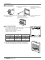
Dimensional Drawings
4. Dimensional Drawings
k
A
B
h
i l
f
e
K
J
C
E
j
a
D
F
(G)
b
c
d
H
(Unit: mm)
Model
F
(G)
H
e
f
h
i
j
186/246BH
A
B
C
D
E
932 882 355 45.5 450
286/366/426BG 1232 1182 355 45.5 450
486BE
1292 1230 570.5 54 680
30
87
750
163 260 61.5 243 212.3 243
110
130
52
66
81
30 158.5
30
87
830
186 298 229.5 243 232 243
116
160
53
59
81
19 158.5
30
120 1006 294 370 253.5 253 217 253
152
186
42
143
82
50
Top view
(unit: mm)
J
K
a
b
c
d
Front view
Inspection hole
(600X600)
Control box
600
1000
H
Front
42
Indoor Unit
600
k
l
172
Piping Diagrams
5. Piping Diagrams
Heat Exchanger
:Cooling
:Heating
LEV
Filter
Sirocco Fan
Filter
lndoor unit
: Thermistor
Refrigerant pipe connection port diameter
[unit: mm(inch)]
Model
Gas
Liquid
15.88(5/8)
9.52(3/8)
19.05(3/4)
9.52(3/8)
19.05(3/4)
9.52(3/8)
CRNN186BHA0
CRNN246BHA0
CRNN286BGA0
CRNN366BGA0
CRNN426BGA0
CRNN486BEA0
Service Manual 43
Wiring Diagrams
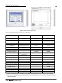
6. Wiring Diagrams
1(L) 2(N)
3
4
(Transmission)
CONNECTOR
NUMBER
CN-POWER
CN-MOTOR2
CN-D/PUMP
CN-COMM
CN-LEV
CN-FLOAT
CN-PIPE
CN-PIPE/O
CN-ROOM
CN-REMO
CN-AIRC
44
SPEC
COLOR
AC POWER SUPPLY
AC FAN MOTOR OUTPUT
DRAIN PUMP OUTPUT
COMMUNICATION
LEV OUTPUT
FLOAT SWITCH INPUT
PIPE SENSOR
DISCHARGE PIPE SENSOR
ROOM SENSOR
REMOTE CONTROLLER
AIR CLEAN
WHITE
YELLOW
WHITE
WHITE
WHITE
BLUE
WHITE
RED
BLUE
WHITE
WHITE
Indoor Unit
DESCRIPTION
AC POWER LINE INPUT FOR INDOOR CONTROLLER
MOTOR OUTPUT OF PHASE CONTROL
AC OUTPUT FOR DRAIN PUMP
COMMUNICATION BETWEEN INDOOR AND OUTDOOR
LEV CONTROL OUTPUT
FLOAT SWITCH SENSING
PIPE THERMISTOR
DISCHARGE PIPE THERMISTOR
ROOM THERMISTOR
REMOTE CONTROL LINE
AIR CLEAN SIGNAL
Exploded View
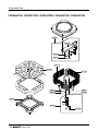
7. Exploded View
• CRNN186BHA0
• CRNN246BHA0
• CRNN286BGA0
• CRNN366BGA0
• CRNN426BGA0
346810
359012
336610-1
336610-2
W0CZZ
263230-3
263230-2
267110
354210
263230-1
268714
249951
352118
152302
55211G
330870
158591
Service Manual 45
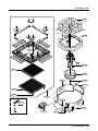
330870
354210
336610-1
46
263230-1
359012-1
Indoor Unit
268714
336610-2
249951
35211C-1
35211C-2
263230-2
359012-2
263230-3
352118
W0CZZ
346810
55211G
158591
267110
152302
Exploded View
• CRNN486BEA0
Replacement Parts List
8. Replacement Parts List
LOCATION
No.
152302
152302
158591
249951
263230-1
263230-2
263230-3
266012
267110
268714
330870
336610-1
336610-2
346810
352118
354210
359012
352115
W0CZZ
LOCATION
No.
152302
158591
249951
263230-1
263230-2
263230-3
266012
267110
268714
330870
336610-1
336610-2
346810
352118
354210
359012
55211G
W0CZZ
LOCATION
No.
152302
158591
249951
263230-1
263230-2
263230-3
266012
267110
268714
330870
336610-1
336610-2
346810
352118
354210
359012-1
359012-2
55211G
W0CZZ
35211C-1
35211C-2
DESCRIPTION
FILTER(MECH),A/C
FILTER(MECH), A/C
PUMP ASSEMBLY, WATER
CONTROL BOX ASSEMBLY, INDOOR
THERMISTOR ASSEMBLY(ROOM)
THERMISTOR ASSEMBLY(PIPE-IN)
THERMISTOR ASSEMBLY(PIPE-OUT)
SWITCH ASSEMBLY, FLOAT
REMOTE CONTROLLER ASSEMBLY
PWB(PCB) ASSEMBLY, MAIN
DRAIN PAN ASSEMBLY
HOUSING(MECH), WRAPPER
HOUSING(MECH), WRAPPER
MOTOR ASEMBLY, INDOOR
TUBE ASSEMBLY, MENIFOLD(INDOOR)
EVAPORATOR ASSEMBLY, FIRST
FAN ASSEMBLY, BLOWER
TUBE ASSEMBLY, EVAPORATOR IN
CAPACITOR, DRAWING
DESCRIPTION
FILTER(MECH), A/C
PUMP ASSEMBLY, WATER
CONTROL BOX ASSEMBLY, INDOOR
THERMISTOR ASSEMBLY(ROOM)
THERMISTOR ASSEMBLY(PIPE-IN)
THERMISTOR ASSEMBLY(PIPE-OUT)
SWITCH ASSEMBLY, FLOAT
REMOTE CONTROLLER ASSEMBLY
PWB(PCB) ASSEMBLY, MAIN
DRAIN PAN ASSEMBLY
HOUSING(MECH), WRAPPER
HOUSING(MECH), WRAPPER
MOTOR ASEMBLY, INDOOR
TUBE ASSEMBLY, MENIFOLD(INDOOR)
EVAPORATOR ASSEMBLY, FIRST
FAN ASSEMBLY, BLOWER
TUBE ASSEMBLY, EXPANSION
CAPACITOR, DRAWING
DESCRIPTION
FILTER(MECH), A/C
PUMP ASSEMBLY, WATER
CONTROL BOX ASSEMBLY, INDOOR
THERMISTOR ASSEMBLY(ROOM)
THERMISTOR ASSEMBLY(PIPE-IN)
THERMISTOR ASSEMBLY(PIPE-OUT)
SWITCH ASSEMBLY, FLOAT
REMOTE CONTROLLER ASSEMBLY
PWB(PCB) ASSEMBLY, MAIN
DRAIN PAN ASSEMBLY
HOUSING(MECH), WRAPPER
HOUSING(MECH), WRAPPER
MOTOR ASEMBLY, INDOOR
TUBE ASSEMBLY, MENIFOLD(INDOOR)
EVAPORATOR ASSEMBLY, FIRST
FAN ASSEMBLY, BLOWER
FAN ASSEMBLY, BLOWER
TUBE ASSEMBLY, EXPANSION
CAPACITOR, DRAWING
TUBE ASSEMBLY,DISCHARGE(IN)
TUBE ASSEMBLY,DISCHARGE(OUT)
Part No.
CRNN186BHA0
5230A30001M
4995A20164M
6871A10089J
5421A20100A
5211A10305B
CRNN246BHA0
5230A30001M
5230A30001M
5859A20002A
4995A20164L
6323AQ3214E
6323AQ3226G
6323AQ3226W
6601A20001E
6711A20043D
6871A10089K
3087A10008D
3660A20017A
3660A20018A
4681A10013C
5211A20465D
5421A20100B
5901A10026A
5211A10305A
2A00986D
Part No.
CRNN286BGA0
CRNN366BGA0
5230A30001L
5859A20002A
4995A10127F
4995A10127G
6323A30004D
6323AQ3226G
6323AQ3226W
6601A20001E
6711A20043D
6871A10089U
6871A10089L
3087A10008C
3660A20019A
3660A20020A
4681A10013A
5211A20416G
5421A10027C
5901A10026A
5211A10426A
2A00986D
Part No.
CRNN486BEA0
5230A30001A
5859A10002A
4995A10127J
6323A30004D
6323AQ3226G
6323AQ3226W
6601A20001E
6711A10002D
6871A10089W
3087A20023A
3661A20009E
3661A20009F
4681A20005K
5211A30076B
5421A20008A
5901A10015E
5901A10015F
5211A10416A
0CZZA20001C
5211A30077A
5211A30094B
CRNN426BGA0
4995A10127H
6871A10089V
5211A20416H
REMARKS
R
R
R
R
R
R
R
R
R
R
R
R
R
R
R
R
R
R
R
REMARKS
R
R
R
R
R
R
R
R
R
R
R
R
R
R
R
R
R
R
REMARKS
R
R
R
R
R
R
R
R
R
R
R
R
R
R
R
R
R
R
R
R
R
Service Manual 47
CRNN-BN / CRNN-BJ
Ceiling Concealed Duct Type (Low static)
1. Specifications .............................................................................49
2. Functions ....................................................................................50
3. Operation Details........................................................................51
4. Dimensional Drawings ...............................................................53
5. Piping Diagrams .........................................................................54
6. Wiring Diagrams .........................................................................55
7. Exploded View ............................................................................56
8. Replacement Parts List..............................................................57
48
Indoor Unit
Specifications
1. Specifications
Model
Cooling Capacity
Heating Capacity
Casing
Dimensions (W*H*D)
Coil
Rows*Steps*Fin Pitch
Moisture removal
Fan
Model
Type
Motor Output
Air Flow Rate(H/M/L)
Unit
W
kcal/h
Btu/h
W
kcal/h
Btu/h
mm
inch
inch
l/h
W
CMM
CFM
Pa
External Static Pressure
Drive
Speed control
Temperature Control
Sound Absorbing Thermal Insulation Material
Safety Device
Pipe Connections Liquid Side
mm(inch)
Gas Side
mm(inch)
Drain Pipe(Internal Dia.)
mm
Net Weight
kg(lbs)
Noise Level(SoundPress,1.5m,H/M/L)
dBA±3
Power Supply
Ø,V,Hz
Power Cable
AWG#:P*mm2
Refrigerant Control
Standard Accessories
CRNN076BNG0
2,100
1,806
7,165
2,363
2,031
8,061
CRNN096BJG0
CRNN126BJG0
2,600
3,500
2,235
3,009
8,871
11,942
2,925
3,923
2,515
3,385
9,980
13,435
Galvanized Steel Plate
783*220*520
873*220*520
873*220*520
30.8*8.7*20.5
34.3*8.7*20.5
34.3*8.7*20.5
2*9*14
2*9*14
2*9*14
1.0
1.0
1.5
D-7K
D-9K
D-12K
Sirocco Fan
Sirocco Fan
Sirocco Fan
13
17
20
6.4/5.9/5.4
7.0/6.5/6.0
10.2/9.2/8.2
226/208/191
247/230/212
360/325/290
0
0
0
Direct
Steps Control
Microprocessor,Thermistat for cooling and heating
Foamed polystyrene
Fuse,Thermal Fuse for Fan Motor
6.35(1/4)
6.35(1/4)
6.35(1/4)
12.7(1/2)
12.7(1/2)
12.7(1/2)
25
25
25
23(50.7)
24(52.9)
24(52.9)
36/34/32
37/35/33
38/36/34
1,220~240,50
1,220~240,50
1,220~240,50
12:3 * 2.5
12:3 * 2.5
12:3 * 2.5
LEV
LEV
LEV
Owner's Manual, Installation Manual, Drain Hose, Clamp Metal, Insulation for
Fitting, Sealing Pads, Clamps, Screws
Notes:1. Capacities are based on the following conditions:
Cooling:
- Indoor Temperature 27°C(80.6°F) DB /19°C(66.2°F) WB
- Outdoor Temperature 35°C(95°F) DB /24°C(75.2°F) WB
- Interconnecting Piping Length 7.5m
- Level Difference of Zero.
Heating:
- Indoor Temperature 20°C(68°F) DB / 15°C(59°F) WB
- Outdoor Temperature 7°C(44.6°F) DB / 6°C(42.8°F) WB
- Interconnecting Piping Length 7.5 m
- Level Difference of Zero.
2. Capacities are Net Capacities.
3. Due to our policy of innovation some specifications may be changed without notification.
4. L.E.V. : Linear Expansion Valve
Conversion Formula
kcal/h = kW x 860
Btu/h = kW x 3414
cfm = m3/min x 35.3
Service Manual 49
Functions
2. Functions
Indoor Unit
• Maintains the room temperature in accordance with the Setting Temperature.
Room temperature control
Starting Current Control
• Indoor fan is delayed for 5 seconds at the starting.
Time Delay Safety Control
• Restarting is inhibited for approx. 3 minutes.
Indoor Fan Speed Control
• High, Med, Low
Soft Dry Operation Mode
Auto Restart
• Intermittent operation of fan at low speed.
• Although the air-conditioner is turned off by a power failure, it is restarted automatically previous operation mode after power supply.
Deice (defrost) control (Heating)
50
• Room temperature sensor. (Thermistor)
• Both the indoor and outdoor fan stops during defrosting.
• Hot start after defrost ends.
Hot-start Control (Heating)
• The indoor fan does not rotate until the evaporator piping
temperature reaches 25°C.
High head height Drain pump
• A standard drain-head height of up to 700mm is possible.
Central Control(Optional)
• It is operating individually or totally by central control function.
Indoor Unit
Duct-Low
Sensing the Room Temperature
Indoor Unit
Operation ON/OFF by Remote controller
Functions
3. Operation Details
(1) The function of main control
■ Time Delay safety Control
• 30sec... The 4-way valve is ceased for 30sec. to prevent the refrigerant-gas abnormal noise when the Heating
operation is OFF or switched to the other operation mode while compress is off.
While compressor is running, it takes 3~5 seconds to switch to another mode.
■ Soft-Dry Operation
• The indoor fan speed is automatically set to the low, so the shift of the indoor fan speed is impossible because of
already being set to the best speed for Dry Operation by microcontroller control.
■ Cooling Mode Operation
• When selecting the Cooling( ) Mode Operation, the unit will operate according to the setting by the remote controller and the operation diagram is as following.
Intake Air Temperature
SET TEMPERATURE +0.5°C
(COMP. ON)
SET TEMPERATURE -0.5°C
(COMP. OFF)
INDOOR FAN
COMPRESSOR
More than
More than
3 minutes
3 minutes
Selecting
fan speed
Low
Selecting
fan speed
Low
Selecting
fan speed
ON
OFF
ON
OFF
ON
Service Manual 51
Operation Details
■ Heating Mode Operation
The unit will operate according to the setting by the remote controller and the operation diagram is shown as following.
Intake Air Temperature
minimum 3min
Setting Temperature +3°C
(Compressor OFF)
A
Setting Temperature
(Compressor ON)
INDOOR FAN
1min
Hot Start
COMPRESSOR
• A point;
• B point;
Selecting
Fan Speed
Low
ON
B
A
minimum
minimum
10sec.
10sec.
Low
OFF
Low
OFF
Selecting fan
speed
ON
OFF
OFF
While the indoor Heat-Exchanger temperature is higher than 40°C fan operates at low speed,
when it becomes lower than 40˚C fan stops.
When the indoor Heat-Exchanger temperature is higher than 42°C, fan operates at seleted fan
speed, when it becomes lower than 39°C, the fan operates at low speed.
■ Hot-Start Control
• The indoor fan does not rotate until the evaporator piping temperature reaches 25°C.
• The operation diagram is as following.
PIPING
TEMPERATURE
25°C
1min
22°C
INDOOR FAN
COMPRESSOR
: Selected Fan
52
Low
Indoor Unit
ON
: Low Fan
: Fan Stop
Dimensional Drawings
4. Dimensional Drawings
H
J
C
E
D
B
F
G
A
Model
A
B
C
D
E
F
G
H
J
CRNN076BNG0
783
667
300
100
500
20
639
120
220
CRNN096BJG0
873
767
300
100
500
20
729
120
220
CRNN126BJG0
873
767
300
100
500
20
729
120
220
Top view
(unit: mm)
Front view
Inspection hole
(600X600)
Control box
600
1000
H
600
Front
Service Manual 53
Piping Diagrams
5. Piping Diagrams
Heat Exchanger
:Cooling
:Heating
LEV
Filter
Sirocco Fan
Filter
lndoor unit
: Thermistor
Refrigerant pipe connection port diameter
[unit: mm(inch)]
Model
Gas
Liquid
Ø12.7(1/2)
Ø6.35(1/4)
CRNN076BNG0
CRNN096BJG0
CRNN126BJG0
54
Indoor Unit
Wiring Diagrams
CN-PIPE/O
6. Wiring Diagrams
(Transmission)
CONNECTOR
NUMBER
CN-POWER
CN-MOTOR2
CN-D/PUMP
CN-COMM
CN-LEV
CN-FLOAT
CN-PIPE
CN-PIPE/O
CN-ROOM
CN-REMO
CN-AIRC
SPEC
COLOR
AC POWER SUPPLY
AC FAN MOTOR OUTPUT
DRAIN PUMP OUTPUT
COMMUNICATION
LEV OUTPUT
FLOAT SWITCH INPUT
PIPE SENSOR
DISCHARGE PIPE SENSOR
ROOM SENSOR
REMOTE CONTROLLER
AIR CLEAN
WHITE
YELLOW
WHITE
WHITE
WHITE
BLUE
WHITE
RED
BLUE
WHITE
WHITE
DESCRIPTION
AC POWER LINE INPUT FOR INDOOR CONTROLLER
MOTOR OUTPUT OF PHASE CONTROL
AC OUTPUT FOR DRAIN PUMP
COMMUNICATION BETWEEN INDOOR AND OUTDOOR
LEV CONTROL OUTPUT
FLOAT SWITCH SENSING
PIPE THERMISTOR
DISCHARGE PIPE THERMISTOR
ROOM THERMISTOR
REMOTE CONTROL LINE
AIR CLEAN SIGNAL
Service Manual 55
Exploded View
7. Exploded View
137214
152302
137213-1
249951
268714
354210
137213-2
263230-1
263230-2
263230-3
346810
135500-2
158591
336610
437214
147901
359012
135500-1
330870
267110
56
Indoor Unit
Replacement Parts List
8. Replacement Parts List
PART NO.
LOCATION No.
DESCRIPTION
CRNN076BNG0
CRNN096BJG0
CRNN126BJG0
REMARKS
135500-1
COVER
3550A20214A
3550A20214B
3550A20214B
R
135500-2
COVER
3550A20215A
3550A20215A
3550A20215A
R
137213-1
PANEL ASSEMBLY,SIDE
3721A20136A
3721A20136A
3721A20136A
R
137213-2
PANEL ASSEMBLY,SIDE
3721A20136B
3721A20136B
3721A20136B
R
137214
PANEL ASSEMBLY,UPPER
3721A20135A
3721A20135B
3721A20135B
R
147901
BARRIER,INDOOR
4790A20043A
4790A20043B
4790A20043B
R
152302
FILTER(MECH),A/C
5230A30009A
5230A30009B
5230A30009B
R
158591
PUMP ASSEMBLY,WATER
5859A20002B
5859A20002B
5859A20002B
R
249951
CONTROL BOX ASSEMBLY,INDOOR
4995A20297A
4995A20297B
4995A20297C
R
263230-1
THERMISTOR ASSEMBLY(ROOM)
6323A30004E
6323A30004E
6323A30004E
R
263230-2
THERMISTOR ASSEMBLY(PIPE-IN)
6323A30002A
6323A30002A
6323A30002A
R
263230-3
THERMISTOR ASSEMBLY(PIPE-OUT)
6323AQ3226T
6323AQ3226T
6323AQ3226T
R
267110
REMOTE CONTROLLER ASSEMBLY
6711A10002D
6711A10002D
6711A10002D
R
268714
PWB(PCB) ASSEMBLY,MAIN
6871A10108A
6871A10108B
6871A10108C
R
330870
DRAIN PAN ASSEMBLY
3087A20019A
3087A20019B
3087A20019B
R
336610
HOUSING ASSEMBLY (MECH)
3661A20022A
3661A20023A
3661A20023A
R
346810
MOTOR ASSEMBLY,INDOOR
4681A20100A
4681A20100B
4681A20100C
R
354210
EVAPORATOR ASSEMBLY,FIRST
5421A20147A
5421A20147B
5421A20147B
R
359012
FAN ASSEMBLY,BLOWER
5901A20027A
5901A20027B
5901A20027B
R
437214
PANEL ASSEMBLY,BASE
3721A20137A
3721A20137B
3721A20137B
R
Service Manual 57
1. Specification ...............................................................................59
2. Installstion...................................................................................60
3. Operation Details........................................................................61
4. Display Function .............................................................................67
5. Dimensional Drawings ...............................................................68
6. Piping Diagrams .........................................................................69
7. Wiring Diagrams .........................................................................70
8. Disassembly of the parts ................................................................71
9. Exploded View ..................................................................................75
10. Replacement Parts List............................................................76
58
Indoor Unit
Indoor Unit
Convertible
CRNN-VB
Convertible Type
Specifications
1. Specifications
Model
Cooling Capacity
Heating Capacity
Unit
W
kcal/h
Btu/h
W
kcal/h
Btu/h
Color
Dimensions (W*H*D)
Casing
Coil
Rows x Columns x FPI
Face Area
Moisture removal
Fan
Type
Motor Output x Number
Air Flow Rate(High)
mm
inch
m2
l/h.
W
cmm
cfm
Drive
Speed control
Temperature Control
Sound Absorbing Thermal Insulation Material
Safety Device
Liquid Side
mm(inch)
Pipe Connections Gas Side
mm(inch)
Drain Pipe(Internal Dia.)
mm
Net Weight
kg(lbs)
Noise Level (Sound Press,1.5m, H/M/L)
dBA±3
Power Supply
Ø,V,Hz
Power Cable
AWG#:P*mm2
Refrigerant Control
Standard Accessories
CRNN186VBA0
5,300
4,557
18,084
5,963
5,127
20,345
CRNN246VBA0
7,032
6,048
24,600
7,735
6,653
26,400
White
1200*615*205
47.24*24.21*8.07
Galvanized Steel plate + Painting
2*12*18
2*12*18
0.26
0.26
2.5
3.0
Cross Flow Fan
30
30
13.5
16
477
565
Direct
Phase control
Microprocessor, Thermostat for cooling and heating
Foamed polystyrene
Fuse, Thermal Fuse for Fan Motor
9.52 (3/8)
15.88 (5/8)
17
30(66.1)
43 / 40 / 37
45/42/39
1,220~240,50
12:3*2.5
L.E.V
Owner Manual, Installation Manual, Paper Pattern for Installation, Drain
Hose, Clamp Metal, Insulation for Fitting, Clamps, Washers, Flare Nut.
Notes:1. Capacities are based on the following conditions:
Cooling:
- Indoor Temperature 27°C(80.6°F) DB /19°C(66.2°F) WB
- Outdoor Temperature 35°C(95°F) DB /24°C(75.2°F) WB
- Interconnecting Piping Length 7.5m
- Level Difference of Zero.
Heating:
- Indoor Temperature 20°C(68°F) DB / 15°C(59°F) WB
- Outdoor Temperature 7°C(44.6°F) DB / 6°C(42.8°F) WB
- Interconnecting Piping Length 7.5 m
- Level Difference of Zero.
2. Capacities are Net Capacities.
3. Due to our policy of innovation some specifications may be changed without notification.
4. L.E.V. : Linear Expansion Valve
Conversion Formula
kcal/h = kW x 860
Btu/h = kW x 3414
cfm = m3/min x 35.3
Service Manual 59
Installstion
Indoor Unit
Convertible
2. Installstion
Indoor Unit
Operation ON/OFF by Remote controller
Sensing the Room Temperature
Room temperature sensor. (Thermistor)
Room temperature control
Maintains the room temperature in accordance with the Setting Temperature.
Starting Current Control
Indoor fan is delayed for 5 seconds at the starting.
Time Delay Safety Control
Restarting is inhibited for approx. 3 minutes.
Indoor Fan Speed Control
High, Med, Low, Chaos
Operation indication Lamps (LED)
--- Lights up in operation
--- Lights up in Sleep Mode
--- Lights up in Timer Mode
--- Lights up in Deice Mode or Hot Start Mode
Soft Dry Operation Mode
Intermittent operation of fan at low speed.
Sleep Mode Auto Control
The fan is switched to low(Cooling), med(Heating) speed.
The unit will be stopped after 1, 2, 3, 4, 5, 6, 7 hours.
Natural Air Control by CHAOS Logic
The fan is switched to intermittent or irregular operation
The fan speed is automatically switched from high to low speed.
Deice (defrost) control (Heating)
Airflow Direction Control
The louver can be set at the desired position or swing
up and down, right and left automatically.
Both the indoor and outdoor fan
stops during deicing.
Hot start after deice ends.
Auto Operation
Hot-start Control (Heating)
The setting temperature, indoor fan speed and desired
operation made are automatically set by fuzzy rule.
60
Indoor Unit
The indoor fan does not rotate until
the evaporator piping temperature
will be reached at 22°C.
Operation Details
3. Operation Details
(1) The function of main control
■ Time Delay Safety Control
• 3min… The compressor is ceased for 3minutes to balance the pressure in the refrigeration cycle.
(Protection of compressor)
• 5sec… Vertical air flow direction control louvers open in 5 seconds to prevent noise between louvers and wind.
• 30sec… The 4-way valve is ceased for 30sec. to prevent the refrigerant-gas abnormal noise when the Heating operation is OFF or switched to the other operation mode while compress is off.
While compressor is running, it takes 3~5 seconds to switch.
■ Airflow Direction Control
• This function is to swing the louver up and down automatically and to set it at the desired position.
• The procedure is as the following.
1st ; Press the ON/OFF Button to operate the product.
2nd ; Press the Airflow Direction Control Button to swing the louver up and down automatically.
3nd ; Repress the Airflow Direction Control Button to set the louver as the desired position.
MODE 0
MODE1
135°
MODE 2
MODE 3
Cooling
MODE 4
MODE 5
MODE 6
MODE 9
(CLOSE)
MODE 7
For Heating Model
• Airflow direction control figure when installed on the
• Airflow direction control figure when installed under
the ceiling.
floor.
OPEN
OPEN
MODE 1
MODE 1
12°
MODE 2
MODE 3
12°
MODE 2
Cooling
Cooling
MODE 3
MODE 4
MODE 4
Heating
MODE 5
135°
Heating
MODE 5
135°
MODE 6
MODE 6
MODE 7
MODE 7
MODE 8
MODE 8
MODE 9
CLOSE
MODE 9
CLOSE
Service Manual 61
Operation Details
When selecting the Cooling( ) Mode Operation, the unit will operate according to the setting by the remote
controller and the operation diagram is as following
Intake Air Temperature
COMP. ON
(SET TEMPERATURE +0.5°C)
COMP. OFF
(SET TEMPERATURE -0.5°C)
INDOOR FAN
COMPRESSOR
More than
More than
3 minutes
3 minutes
Selecting
fan speed
Low
Selecting
fan speed
Low
Selecting
fan speed
ON
OFF
ON
OFF
ON
■ Cooling or Heating Mode with Sleep Mode Auto Operation
• When selecting the Cooling(
) or the Heating(
) combined with the Sleep Mode Auto Operation(
operation diagram is as following.
Cooling Mode with the Sleep Mode
• The setting temperature will be raised by 1°C 30minutes later and by 2°C 1 hour later.
• The operation will be stopped after 1, 2, 3, 4, 5, 6, 7 hours.
30 minutes
Intake Air Temperature
), the
30 minutes
1°C
COMP. ON
(SET TEMPERATURE +0.5°C)
1°C
COMP. OFF
(SET TEMPERATURE -0.5°C)
More than
3 minutes
More than
3 minutes
INDOOR FAN
Low
Low
Low
Low
Low
COMPRESSOR
ON
OFF
ON
OFF
ON
Heating Mode with the Sleep Mode.
The operation will be stopped after 1, 2, 3, 4, 5, 6, 7 hours.
Setting Temperature +3°C
(Compressor OFF)
Setting Temperature
(Compressor ON)
Indoor Fan
Compressor
62
Indoor Unit
Med.
Med.
Med.
Med.
Med.
Med.
ON
OFF
ON
OFF
ON
OFF
Indoor Unit
Convertible
■ Cooling Mode Operation
Operation Details
■ Natural wind by CHAOS logic
For more fresh feeling than other fan speed mode, press
the indoor fan Speed Selector and set to CHAOS mode.
In this mode, the wind blows like natural breeze by automatically changing fan speed according to the CHAOS
logic.
Intake Air temperature
Setting CHAOS Natural wind
Cooling on temperature.
(Setting temperature +0.5)
Setting temp.
Cooling off temperature
(Setting temperature -0.5)
INDOOR FAN
OUTDOOR FAN/COMP.
: Setting fan speed
: CHAOS Natural wind
: LOW
: COMP ON
: COMP OFF
GRAPH of Natural wind by the CHAOS logic (During Cooling operation)
Intake Air temperature
Setting CHAOS Natural wind
Heating off temperature
(Setting temperature +3.0)
Heating on temperature
(Setting temperature)
30sec
INDOOR FAN
LOW OR STOP
OUTDOOR FAN/COMP.
: Setting fan speed
: CHAOS Natural wind
: LOW
: COMP ON
: COMP OFF
GRAPH of Natural wind by the CHAOS logic (During Heating operation)
Service Manual 63
Operation Details
The unit will operate according to the setting by the remote controller and the operation diagram is shown
as following.
• For Heating Model
Indoor piping temperature
28°C
26°C
Intake Air temperature
Setting temperature +3.0˚C
(Compressor OFF)
Setting temperature
(Compressor ON)
COMPRESSOR
INDOOR FAN
minimum
1min.
minimum
3min.
ON
OFF
ON
OFF
ON
OFF
ON
OFF
ON
Low Fan
Selected Fan
Low Fan
ON
OUTDOOR FAN
Fan
Stops
minimum
30sec.
minimum
3min.
Low
Fan
Selected
Fan
4-WAY VALVE
minimum
1min.
Fan Stop
Low
Fan
Selected
Fan
ON
■ Hot-Start Control
The indoor fan does not rotate until the evaporator piping temperature will be reached to 22 .
During heating operation, if piping temperature falls below 28°C fan stops.
The operation diagram is as following.
PIPING
TEMPERATURE
28°C
1min
26°C
INDOOR FAN
ON
COMPRESSOR
: Selected Fan
64
Indoor Unit
: Low Fan
: Fan Stop
Indoor Unit
Convertible
■ Heating Mode Operation
Operation Details
■ Soft Dry Operation
• During Soft Dry Operation, the compressor ON temperature is the setting temperature plus 1°C, the compressor
OFF temperature is the setting temperature minus 0.5°C.
• When the room temperature rises over the compressor ON temperature, the operation mode is switched to
the cooling mode.
• When the room temperature falls between the compressor ON temperature and OFF temperature, the operation mode is switched to the Soft Dry Operation.
In this temperature range, 10min. Dry Operation, 7min operation OFF. During 10min Dry operation, if the room
temperature falls below compressor OFF temperature, Compressor OFF.
• In dehumidify mode, control of fan speed is as following.
Intake Air temperature
Setting temperature +1.0˚C
(Compressor ON)
Setting temperature
Setting temperature -0.5˚C
(Compressor OFF)
Cooling 2min.58sec. 10min.
COMPRESSOR
7min.
10min. Within 7min. Cooling 2min.58sec.
ON
OFF
ON
OFF
ON
OFF
OUTDOOR FAN
ON
OFF
ON
OFF
ON
OFF
INDOOR FAN
Selected
Fan
ON
OFF
ON
OFF
ON
OFF
ON
OFF
Selected
Fan
Low Fan
Low Fan
■ Forced operation
• If you lose wireless remote controller, you can operate the unit with forced operation switch.
• The standard conditions are as following.
Room Temperature
24°C
21°C Room Temperature
24°C
Room Temperature 21°C
Operation Mode
Cooling
Soft Dry
Heating
FAN Speed
High
Soft Dry Rule
High
Setting Temperature
22°C
Air Intake Temperature
24°C
• Unit operates in low fan mode for first 15 seconds, then switched to proper operation mode according to
intake Air temperature.
Forced
Operation Button
Press the Forced Operation Button.
R
• Press the Forced Operation Button once
again to stop operation.
Service Manual 65
Operation Details
If the temperature of the indoor coil is below -2°C after 7 minutes from starting the compressor,
the compressor and the outdoor fan is stopped, and then after 3 minute delay of the compressor
and the temperature of the indoor coil is over 7°C, the compressor and the outdoor fan is reoperated.
Indoor fan operates at low speed (comp. OFF) or at selected speed (comp. ON)
■ Inlet grille open
Once the inlet grille is opened during operation of the unit, the unit automatically stops operation and the lamps
will be turned-off. But memorized functions are still available.
When the inlet grille is closed again, the unit become waiting state for operation. From then, the unit can be
operated by forced operation button or Start/Stop button of remote controller.
■ Test Operation
• When pressing forced operation switch about 3 seconds, the unit operates in cooling mode at high speed
fan regardless of room temperature and resets in 18 min.
• During test operation, if remote controller signal is received, the unit operates as remote controller sets.
■ Auto Restarting Operation
• When the power is restored after a sudden power failure while in appliance is in operation, the mode
before the power failure is kept on the memory and the appliance should operate automatically in the
mode kept in the memory.
• Operation Mode that is kept on the memory
- State of Operation ON/OFF
- Operation Mode/Setting Temperature /Selected airflow Speed
- Sleep Timer Mode/Remaining Time of Sleep Timer(unit of hour)
• If no input by the remote controller or no switching of the slide switch within 7 hours after the appliance
operates by the Auto Restarting operation, the appliance is forced to stop at the moment of 7 hours
elapse.
66
Indoor Unit
Indoor Unit
Convertible
■ Protection of the evaporator pipe from frosting
Display Function
4. Display Function
Operation Indicator
• Coolling, Soft Dry, Fan, Heating
Timer Indicator
• Timer Mode
Sleep Timer Indicator
• Sleep Mode
Deice Indicator
• Hot-start, Deice
Note)
For normal operation after checking by test mode, you should press SW1 nine times for resetting or reconnect the power cord.
Service Manual 67
Dimensional Drawings
Indoor Unit
Convertible
5. Dimensional Drawings
1200
61
5
R
205
63
38
26
5
250
39
2
36
46
8
175
76
10
(Installation Plate)
(Rear Side)
36
(Unit: mm)
More than
20cm
More than
20cm
R
More than
20cm
R
More than eye-level
(Ceiling installation)
68
Indoor Unit
(Floor/Wall installation)
More than
20cm
Piping Diagrams
6. Piping Diagrams
Heat Exchanger
C.F.F.
LEV
:Cooling
:Heating
Filter
Filter
lndoor unit
: Thermistor
Refrigerant pipe connection port diameter
[unit: mm(inch)]
Model
CRNN186VBA0
Gas
Liquid
15.88(5/8)
9.52(3/8)
CRNN246VBA0
Service Manual 69
Wiring Diagrams
Indoor Unit
Convertible
7. Wiring Diagrams
1(L) 2(N)
3
4
(Transmission)
CONNECTOR
NUMBER
CN-POWER
CN-MOTOR2
CN-COMM
CN-DISP1
CN-LEV
CN-STEP/M1
CN-STEP/M2
CN-DOOR
CN-PIPE
CN-PIPE/O
CN-ROOM
CN-REMO
70
SPEC
COLOR
AC POWER SUPPLY
AC FAN MOTOR OUTPUT
COMMUNICATION
DISPLAY
LEV OUTPUT
STEP MOTOR
STEP MOTOR
DOOR SENSE
PIPE SENSOR
DISCHARGE PIPE SENSOR
ROOM SENSOR
REMOTE CONTROLLER
WHITE
YELLOW
WHITE
WHITE
WHITE
WHITE
WHITE
WHITE
WHITE
RED
BLUE
WHITE
Indoor Unit
DESCRIPTION
AC POWER LINE INPUT FOR INDOOR CONTROLLER
MOTOR OUTPUT OF PHASE CONTROL
COMMUNICATION BETWEEN INDOOR AND OUTDOOR
DISPLAY OF INDOOR STATUS
LEV CONTROL OUTPUT
STEP MOTOR OUTPUT
STEP MOTOR OUTPUT
SENSING DOOR STATUS(OPEN/CLOSE)
PIPE THERMISTOR
DISCHARGE PIPE THERMISTOR
ROOM THERMISTOR
REMOTE CONTROL LINE
Disassembly of the parts
8. Disassembly of the parts
Warning :
Disconnect the unit from power supply before making
any checks.
Be sure the power switch is set to “OFF”.
1. Remove the air filter.
• Pull the inlet grille slightly toward you.
• Pull out the air filter. (2 pieces)
R
Inlet Grille
2. Remove the girlle from chassis
• Remove the screws securing the side plate and
push to the bottom-side.
• Unhook the hanger from the hanger screw at the
left and the right side.
• Pick out the inlet grille.
R
1
4
3
Hanger
Hanger
Screw
2
3. Remove the lower air guide
• Remove a screw of both side fixing "barrier airguide".
• Remove the screws of both sides of the lower
air-guide.
• Remove the lower air-guide toward “arrow
mark” by turning upwards as shown in figure.
R
Barrier Air guide
Lower Air guide
Service Manual 71
Disassembly of the parts
Indoor Unit
Convertible
4. Remove air guide upper, crossflow fan and
motor.
• Remove the screws of both sides and center
securing the upper air-guide.
• Remove 2 screws fastening the bracket of door
switch.
Door
Switch
R
• Remove a bearing assembly by removing a
screw and the bearing cover.
• Remove 4 screws securing the motor cover.
• Loosen the screw securing the crossflow fan to
the fan motor shaft. (do not remove)
• Remove the crossflow fan by sliding it out from
the shaft of fan motor.
Bearing
Cover
Bearing
Motor
Cover
5. Remove the control box Assembly.
• Disconnect the step motor connector, fan
motor connector, display PCB connector,
thermistor connector and door switch connector from the main PCB.
• If necessary, disconnect power supply cord
and connecting cable from the terminal block
and remove the cord clamp screw.
• Remove 2 screws securing the control box
and pick out the control box carefully.
72
Indoor Unit
R
R
Disassembly of the parts
6. Remove the front panel.
• Remove the screws of both sides fixing the
front panel.
• Push the upper side of front panel strongly to
pull out the front panel from the inner hook of
diffuser frame.
• Pull down the front panel carefully not so as
to harm the display PCB wires and thermistor
wires.
7. Remove the diffuser assembly.
• Remove the screws of both side of diffuser
assembly. (4 pieces)
• Push the upper side of cabinet strongly to
pull out the inner hook of diffuser frame from
the cabinet hole.
• Take up the diffuser frame carefully not so as
to harm the display PCB wires and the step
motor wires.
Diffuser frame
Diffuser
frame
Hook
Front
Panel
Front
Panel
R
Diffuser
frame
Hook
Cabinet
R
8. Remove display PCB assembly.
• Remove the screws at the both side of display cover.
• If necessary, disconnect the display PCB
connector from PCB assembly.
• Remove 2 screws of PCB assembly.
Display Cover
Service Manual 73
Disassembly of the parts
Step Motor
Vane Supporter
Lower Vane
Upper Vane
10. Remove the drain pan assembly.
• Remove the both side of screws. (4 pieces)
• Pull out the drain pan assembly.
• Be careful not to harm to the EPS packing of
drain pan and the tubings of evaporator.
11. Remove the evaporator.
• Remove the screws of both sides securing
the EVA barrier-R/L on the side cabinet.
• Remove the screws which fasten the barrier
on the evaporator and take out the barrier
assembly.
• Remove the evaporator assembly by sliding
toward arrow mark. (As shown in figure)
EVA. Barrier-L
Side Cabinet
EVA. Barrier-R
74
Indoor Unit
Indoor Unit
Convertible
9. Remove the vane-upper, vane-lower and step
motor.
• Remove 2 screws securing the step motor
assembly and pull it out from the vanes carefully.
• Unhook the vanes from the vane supporter
and remove the upper vane and lower vane
by pulling the center of vanes with care.
NER
ANU
ANU
AL
EM
'S M
VIC
INST
ALLA
TION
MAN
UAL
OW
SER
AL
137211
159901
159911
146811
235450
237900
268712
132100
135414
152302
330870
354210
346810
135316
359010
W0CZZ
268714
166000
249951
733010-1
342800
35211A
352115
263230-3
263230-2
263230-1
166000
733010-2
130911
Exploded View
9. Exploded View
Service Manual 75
Replacement Parts List
PART NO.
LOCATION No.
DESCRIPTION
CRNN186VBA0
CRNN246VBA0
REMARKS
130911
CABINET ASSEMBLY,INDOOR
3091AP2533A
R
132100
FRAME
3022AP1283B
R
135303
GRILLE,INLET
5236AP1236A
R
135314
GRILLE ASSEMBLY,INLET SUB
5237AP2817B
R
135316
GRILLE ASSEMBLY,DIFFUSER(INDOOR)
3531A10272B
R
137211
PANEL ASSEMBLY,FRONT(INDOOR)
3720AP2767P
R
146811
MOTOR ASSEMBLY,STEP
4681AR2727G
R
152302
FILTER(MECH),A/C
5230AP7093A
R
159901
VANE ASSY
5991AP7334C
R
159911
VANE ASSY,HORIZONTAL
5991AP2867B
R
166000
SWITCH,PUSH
6600AP2059B
R
166000
SWITCH,PUSH
6600AP2059B
R
235450
DISPLAY ASSEMBLY (MECH)
3545AP7224B
R
237900
WINDOW,DISPLAY
3790AP7080A
R
249951
CONTROL BOX ASSEMBLY,INDOOR
4995A10107A
4995A10107D
R
263230-1
THERMISTOR ASSEMBLY(ROOM)
6323AQ3214E
R
263230-2
THERMISTOR ASSEMBLY(PIPE-IN)
6323A30002C
R
263230-3
THERMISTOR ASSEMBLY(PIPE-OUT)
6323AQ3226Y
R
267110
REMOTE CONTROLLER ASSEMBLY
6711A10002A
R
268712
PWB(PCB) ASSY,DISPLAY
6871AQ3263A
R
268714
PWB(PCB) ASSEMBLY,MAIN
330870
DRAIN PAN ASSEMBLY
342800
BEARING
346810
MOTOR ASSEMBLY,INDOOR
352115
TUBE ASSEMBLY,EVAPORATOR IN
35211A
TUBE ASSEMBLY,SUCTION INDOOR
352150
HOSE ASSY,DRAIN
354210
EVAPORATOR ASSEMBLY,FIRST
359010
FAN ASSY,CROSS FLOW
5901AR2351E
R
733010
PLATE ASSEMBLY,INSTALL(R)
3301AP7519A
R
733010
PLATE ASSEMBLY,INSTALL(L)
3301AP7519B
R
W0CZZ
CAPACITOR, DRAWING
3H00671A
R
76
Indoor Unit
6871A10089M
6871A10089R
R
3087AP7233A
R
3H02821B
R
4681AP2306M
4681AP2306N
5211A10332A
5211AP2813E
R
5211AP2813J
5251AP2460B
5421AP2812B
R
R
R
5421AP2812A
R
Indoor Unit
Convertible
10. Replacement Parts List
CRNN-SR / CRNN-ST
Wall Mounted Type
1. Specification ...............................................................................78
2. Functions ....................................................................................79
3. Operation Details........................................................................80
4. Dimensional Drawings ...............................................................85
5. Piping Diagrams .........................................................................86
6. Wiring Diagrams .........................................................................87
7. Disassembly of the parts.................................................................88
8. Exploded View ............................................................................90
9. Replacement Parts List..............................................................92
Service Manual 77
Specifications
1. Specifications
Model
Cooling Capacity
Color
Coil
Rows x Columns x FPI
Face Area
Moisture removal
Fan
Type
Motor Output x Number
Air Flow Rate(High)
m2
l/h.
W
cmm
cfm
Drive
Speed control
Temperature Control
Sound Absorbing Thermal Insulation Material
Air Filter
Safety Device
Liquid Side
mm(inch)
Pipe Connections Gas Side
mm(inch)
Drain Pipe(Internal Dia.)
mm
Net Weight
kg(lbs)
Noise Level (Sound Press,1m, H/M/L)
dBA±3
Power Supply
Ø,V,Hz
Power Cable
AWG#:P*mm2
Refrigerant Control
Standard Accessories
Operation Manual, Installation Manual, Installation Panel, Paper Pattern for
Installation, Clamps, Screws
Notes:1. Capacities are based on the following conditions:
Cooling:
- Indoor Temperature 27°C(80.6°F) DB /19°C(66.2°F) WB z
- Outdoor Temperature 35°C(95°F) DB /24°C(75.2°F) WB
- Interconnecting Piping Length 7.5m
- Level Difference of Zero.
Heating:
- Indoor Temperature 20°C(68°F) DB / 15°C(59°F) WB
- Outdoor Temperature 7°C(44.6°F) DB / 6°C(42.8°F) WB
- Interconnecting Piping Length 7.5 m
- Level Difference of Zero.
2. Capacities are Net Capacities.
3. Due to our policy of innovation some specifications may be changed without notification.
4. L.E.V. : Linear Expansion Valve
78
Indoor Unit
Conversion Formula
kcal/h = kW x 860
Btu/h = kW x 3414
cfm = m3/min x 35.3
Indoor Unit
Dimensions (W*H*D)
CRNN076SRA0 CRNN096SRA0 CRNN126SRA0 CRNN186STA0
2,100
2,600
3,500
5,300
1,806
2,235
3,009
4,557
7,165
8,871
11,942
18,084
2,363
2,925
3,938
5,963
2,031
2,515
3,385
5,127
8,061
9,980
13,435
20,345
900*285*156
900*285*156
900*285*156
1090*314*172
35.4*11.2*6.1
35.4*11.2*6.1
35.4*11.2*6.1
42.9*12.4*6.8
White
White
White
White
2*12*20
2*12*20
2*12*20
2*13*20
0.13
0.13
0.13
0.14
1.0
1.0
1.2
2.2
Cross Flow Fan Cross Flow Fan Cross Flow Fan Cross Flow Fan
7.5
7.5
14.4
22
5.6
7.0
9.5
13.5
196
247
336
477
Direct
Phase control
Microprocessor, Thermostat for cooling and heating
Foamed polystyrene
Resin Net(Washable)
Fuse
Fuse
Fuse
Fuse
6.35 (1/4)
6.35 (1/4)
6.35 (1/4)
9.52(3/8)
12.7 (1/2)
12.7 (1/2)
12.7 (1/2)
15.88 (5/8)
25
25
25
25
7(15.4)
7(15.4)
8(17.6)
12(26.5)
30/33/27
34/31/28
36/33/30
40/37/34
1,220~240,50
1,220~240,50
1,220~240,50
1,220~240,50
12:3*2.5
12:3*2.5
12:3*2.5
12:3*2.5
L.E.V
L.E.V
L.E.V
L.E.V
Wall Mounted
Heating Capacity
Unit
W
kcal/h
Btu/h
W
kcal/h
Btu/h
mm
inch
Functions
2. Functions
Indoor Unit
Operation ON/OFF by Remote controller
Sensing the Room Temperature
• Room temperature sensor. (THERMISTOR)
Room temperature control
• Maintains the room temperature in accordance with the Setting temperature
Starting Current Control
• Indoor fan is delayed for 5 seconds at the starting.
Time Delay Safety Control
• Restarting is inhibited for approx. 3 minutes.
Indoor Fan Speed Control
• High, Med, Low, Chaos
Operation indication Lamps (LED)
--- Lights up in operation
--- Lights up in Sleep Mode
--- Lights up in Timer Mode
--- Lights up in Deice Mode
--- Indicate the setting temperature.
Auto Restart
Health Dehumidification Operation
• Intermittent operation of fan at low speed.
Sleep Mode Auto Control
• The fan is switched to low(Cooling), med(Heating) speed.
• The unit will be stopped after 1, 2, 3, 4, 5, 6, 7 hours.
Natural Air Control by CHAOS Logic
• The fan is switched to intermittent or irregular operation
• The fan speed is automatically switched from high to low speed.
Airflow Direction Control
• The louver can be set at the desired position or swing
up and down automatically.
• Although the air conditioner is
turned off by a power failure, it
is restarted automatically to
previous operation mode after
power suply.
Deice (defrost) control (Heating)
• Both the indoor and outdoor fan
stops during deicing.
• Hot start after deice ends.
Hot-start Control (Heating)
• The indoor fan does not rotate
until the evaporator piping temperature will be reached at 28°C.
Service Manual 79
Operation Details
3. Operation Details
(1) The function of main control
Sleep Timer Indicator
• On while in sleep timer mode, off when sleep timer cancel or appliance operation pause
Timer Indicator
• On while in timer mode (on/off), off when timer mode is completed or canceled
Defrost Indicator
• Off except when hot start during heating mode operation or while in defrost control
■ Cooling Mode Operation
• When the intake air temperature reaches 0.5°C below the setting temperature, the compressor and the outdoor fan stop.
• When it reaches 0.5°C above the setting temperature, they start to operate again.
Compressor ON Temperature
➲ Setting Temperature +0.5°C
Compressor OFF Temperature
➲ Setting Temperature -0.5°C
• While in compressor running, operating with the airflow speed set by the remote control. While in compressor not running, operating with the low airflow speed regardless of the setting.
■ Soft Dry Operation Mode
• When the dehumidification operation input by the remote control is received, the intake air temperature is
detected and the setting temperature is automatically set according to the intake air temperature.
26°C ≤ Intake Air Temperature
➲ 25°C
24°C ≤ Intake Intake Air Temperature <26°C
➲ Intake Air Temperature -1°C
18°C ≤ Intake Intake Air Temperature <24°C
➲ Intake Air Temperature -0.5°C
Intake Air Temperature <18°C
➲ 18°C
• While in compressor off, the indoor fan repeats low airflow speed and pause.
• While the intake air temperature is between compressor on temperature and compressor off temperature,
10-min dehumidification operation and 4-min compressor off repeat.
Compressor ON temperature
➲ Setting Temperature +0.5°C
Compressor OFF temperature
➲ Setting Temperature -0.5°C
• In 10-min dehumidification operation, the indoor fan operates with the low airflow speed.
■ Heating Mode Operation
• When the intake air temperature reaches +3°C above the setting temperature, the compressor is turned
off. When below the setting temperature, the compressor is turned on.
Compressor ON temperature
➲ Setting temperature
Compressor OFF temperature
➲ Setting temperature+3°C
• While in compressor on, the indoor fan is off when the indoor pipe temperature is below 26°C, when above
28°C , it operates with the low or setting airflow speed.
80
Indoor Unit
Indoor Unit
Operation Indicator
• On while in appliance operation, off while in appliance pause
Wall Mounted
• DISPLAY
Operation Details
• While in compressor off, the indoor fan is off when the indoor pipe temperature is below 33°C, when above
35°C , it operates with the low airflow speed.
• If overloaded while in heating mode operation, in order to prevent the compressor from OLP operation, the
outdoor fan is turned on/off according to the indoor pipe temperature
• While in defrost control, both of the indoor and outdoor fans are turned off.
■ Fuzzy Operation
• When any of operation mode is not selected like the moment of the power on or when 3 hrs has passed
since the operation off, the operation mode is selected.
• When determining the operation mode, the compressor, the outdoor fan, and the 4 way valve are off and
only the indoor fan is operated for 15 seconds. Then an operation mode is selected according to the intake
air temperature at that moment as follows.
24°C ≤ Inatake Air Temperature
➲ Fuzzy Operation for Cooling
21°C ≤ Inatake Air Temperature <24°C
➲ Fuzzy Operation for Dehumidification
Inatake Air Temperature <21°C
➲ Fuzzy Operation for Heating
• If any of the operation modes among cooling / dehumidification / heating mode operations is carried out for
10 sec or longer before Fuzzy operation, the mode before Fuzzy operation is operated.
1) Fuzzy Operation for Cooling
• According to the setting temperature selected by Fuzzy rule, when the intake air temperature is 0.5°C or
more below the setting temperature, the compressor is turned off. When 0.5°C or more above the setting
temperature, the compressor is turned on.
Compressor ON Temperature
➲ Setting Temperature +0.5°C
Compressor OFF Temperature
➲ Setting Temperature – 0.5°C
• At the beginning of Fuzzy mode operation, the setting temperature is automatically selected according to
the intake air temperature at that time.
26°C≤ Intake Air Temperature
➲ 25°C
24°C≤ Intake Air Temperature <26°C
➲ Intake Air Temperature – 1°C
22°C≤ Intake Air Temperature <24°C
➲ Intake Air Temperature – 0.5°C
18°C≤ Intake Air Temperature <22°C
➲ Intake Air Temperature
Intake Air Temperature <18°C
➲ 18°C
• When the Fuzzy key (Temperature Control key) is input after the initial setting temperature is selected, the
Fuzzy key value and the intake air temperature at that time are compared to select the setting temperature
automatically according to the Fuzzy rule.
• While in Fuzzy operation, the airflow speed of the indoor fan is automatically selected according to the temperature.
Service Manual 81
Operation Details
2) Fuzzy Operation for Dehumidification
• According to the setting temperature selected by Fuzzy rule, when the intake air temperature is 3°C or more
above the setting temperature, the compressor is turned off. When below the setting temperature, the compressor is turned on.
Compressor ON Temperature
➲ Setting Temperature
Compressor OFF Temperature
➲ Setting Temperature + 3°C
• At the beginning of Fuzzy mode operation, the setting temperature is automatically selected according to the
intake air temperature at that time.
20°C≤Intake Air Temperature
➲ Intake Air Temperature + 0.5°C
Intake Air Temperature <20°C
➲ 20°C
• When the Fuzzy key (Temperature Control key) is input after the initial setting temperature is selected, the
Fuzzy key value and the intake air temperature at that time are compared to select the setting temperature
automatically according to the Fuzzy rule.
• While in Fuzzy operation, the airflow speed of the indoor fan is set to the high or the medium according to
the intake air temperature and the setting temperature.
■ Airflow Speed Selection
• The airflow speed of the indoor fan is set to high, medium, low, or chaos (auto) by the input of the airflow
speed selection key on the remote control.
■ On-Timer Operation
• When the set time is reached after the time is input by the remote control, the appliance starts to operate.
• The timer LED is on when the on-timer is input. It is off when the time set by the timer is reached.
• If the appliance is operating at the time set by the timer, the operation continues.
While in Fuzzy operation, the airflow speed of the indoor fan is automatically selected according to the temperature.
■ Off-Timer Operation
• When the set time is reached after the time is input by the remote control, the appliance stops operating.
• The timer LED is on when the off-timer is input. It is off when the time set by the timer is reached.
• If the appliance is on pause at the time set by the timer, the pause continues.
82
Indoor Unit
Indoor Unit
3) Fuzzy Operation for Heating
Wall Mounted
• According to the setting temperature selected by Fuzzy rule, when the intake air temperature is 0.5°C or
more below the setting temperature, the compressor is turned off. When 0.5°C or more above the setting
temperature, the compressor is turned on.
Compressor ON Temperature
➲ Setting Temperature + 0.5°C
Compressor OFF Temperature
➲ Setting Temperature – 0.5°C
• At the beginning of Fuzzy mode operation, the setting temperature is automatically selected according to the
intake air temperature at that time.
26°C ≤ Intake Air Temperature
➲ 25°C
24°C ≤ Intake Air Temperature <26°C
➲ Intake Air Temperature – 1°C
22°C ≤ Intake Air Temperature <24°C
➲ Intake Air Temperature – 0.5°C
18°C ≤ Intake Air Temperature <22°C
➲ Intake Air Temperature
Intake Air Temperature <18°C
➲ 18°C
• When the Fuzzy key (Temperature Control key) is input after the initial setting temperature is selected, the
Fuzzy key value and the intake air temperature at that time are compared to select the setting temperature
automatically according to the Fuzzy rule.
• While in Fuzzy operation, the airflow speed of the indoor fan repeats the low airflow speed or pause as in
dehumidification operation.
Operation Details
■ Off-Timer <=> On-Timer Operation
• When the set time is reached after the on/off time is input by the remote control, the on/off-timer operation is
carried out according to the set time.
■ Sleep Timer Operation
• When the sleep time is reached after < 1,2,3,4,5,6,7,0(cancel) hour > is input by the remote control while in
appliance operation, the operation of the appliance stops.
• While the appliance is on pause, the sleep timer mode cannot be input.
• While in cooling mode operation, 30 min later since the start of the sleep timer, the setting temperature
increases by 1°C. After another 30 min elapse, it increases by 1°C again.
• When the sleep timer mode is input while in cooling cycle mode, the airflow speed of the indoor fan is set to
the low.
• When the sleep timer mode is input while in heating cycle mode, the airflow speed of the indoor fan is set to
the medium.
■ Chaos Swing Mode
• By the Chaos Swing key input, the upper/lower vane automatically operates with the Chaos Swing or they
are fixed to the desired direction.
• While in Chaos Swing mode, the angles of cooling and heating cycle operations are different.
■ Chaos Natural Wind Mode
• When the Chaos Natural Wind mode is selected and then operated, the high, medium, or low speed of the
airflow mode is operated for 2~15 sec. randomly by the Chaos Simulation.
■ Jet Cool Mode Operation
• While in heating mode or Fuzzy operation, the Jet Cool key cannot be input. When it is input while in the
other mode operation (cooling, dehumidification, ventilation), the Jet Cool mode is operated.
• In the Jet Cool mode, the indoor fan is operated at super-high speed for 30 min at cooling mode operation.
• In the Jet Cool mode operation, the room temperature is controlled to the setting temperature, 18°C.
• When the sleep timer mode is input while in the Jet Cool mode operation, the Jet Cool mode has the priority.
• When the Jet Cool key is input, the upper/lower vanes are reset to those of the initial cooling mode and then
operated in order that the air outflow could reach further.
■ Auto restart
• In case the power comes on again after a power failure, Auto Restarting Operation is the function to operate
procedures automatically to the previous operating conditions.
Service Manual 83
Operation Details
■ Forced Operation
• Operation procedures when the remote control can't be used.
• The operation will be started if the power button is pressed.
• If you want to stop operation, re-press the button.
Room temperature < 21°C
Operating mode
Cooling
Healthy Dehumidification
Heating
Indoor FAN Speed
High
High
High
Setting Temperature
22°C
23°C
24°C
• While in forced operation, the key input by the remote control has no effect and the buzzer sounds 10 times
to indicate the forced operation.
■ Test operation
• During the TEST OPERATION, the unit operates in cooling mode at high speed fan, regardless of room
temperature and resets in 18±1 minutes.
• During test operation, if remote controller signal is received, the unit operates as remote controller sets.
If you want to use this operation, open the front panel upward and Press the power button let it be pressed
for about 3 seconds.
• If you want to stop the operation, re-press the button.
■ Protection of the evaporator pipe from frosting
• If the indoor pipe temperature is below 0°C in 7 min. after the compressor operates without any pause while
in cooling cycle operation mode, the compressor and the outdoor fan are turned off in order to protect the
indoor evaporator pipe from frosting.
• When the indoor pipe temperature is 7°C and higher after 3 min. pause of the compressor, the compressor
and the outdoor fan is turned on according to the condition of the room temperature.
■ Buzzer Sounding Operation
• When the appliance-operation key is input by the remote control, the short "beep-beep-" sounds.
• When the appliance-pause key is input by the remote control, the long "beep—" sounds.
84
Indoor Unit
Indoor Unit
21°C ≤ Room temperature < 24°C
Wall Mounted
Room temperature ≥ 24°C
Dimiensional Drawings
4. Dimiensional Drawings
H
D
W
Installation plate
(Unit : mm)
Model No.
CRNN076SRA0
CRNN096SRA0
CRNN126SRA0
CRNN186STA0
W
H
D
900
285
156
1090
314
172
Service Manual 85
Piping Diagrams
5. Piping Diagrams
Heat Exchanger
:Cooling
:Heating
LEV
Filter
lndoor unit
: Thermistor
Refrigerant pipe connection port diameter
[unit: mm(inch)]
Model
Gas
Liquid
12.7(1/2)
6.35(1/4)
15.88(5/8)
9.52(3/8)
CRNN076SRA0
CRNN096SRA0
CRNN126SRA0
CRNN186STA0
86
Indoor Unit
Indoor Unit
C.F.F
Wall Mounted
Filter
Wiring Diagrams
6. Wiring Diagrams
(Transmission)
CONNECTOR
NUMBER
CN-POWER
CN-MOTOR2
CN-ACDC
CN-COMM
CN-DISP1
CN-DISP2
CN-LEV
CN-UD
CN-TH1
CN-PIPEOUT
SPEC
COLOR
AC POWER SUPPLY
AC FAN MOTOR OUTPUT
AC/DC CONNECTION
COMMUNICATION
DISPLAY
DISPLAY
LEV OUTPUT
STEP MOTOR
ROOM/PIPE SENSOR
DISCHARGE PIPE SENSOR
WHITE
YELLOW
WHITE
WHITE
BLUE
WHITE
WHITE
WHITE
WHITE
RED
DESCRIPTION
AC POWER LINE INPUT FOR INDOOR CONTROLLER
MOTOR OUTPUT OF PHASE CONTROL
CONNECTION BETWEEN AC PCB AND DC PCB
COMMUNICATION BETWEEN INDOOR AND OUTDOOR
DISPLAY OF INDOOR STATUS
DISPLAY OF INDOOR STATUS
LEV CONTROL OUTPUT
STEP MOTOR OUTPUT
ROOM & PIPE THERMISTOR
DISCHARGE PIPE THERMISTOR
Service Manual 87
Disassembly of the parts
7. Disassembly of the parts
To remove the Grille from the Chassis.
• Set the up-and-down air discharge louver to open
position (horizontally) by finger pressure.
• Remove the securing screws
• To remove the Grille, pull the lower left and right
side of the grille toward you (slightly tilted) and lift
it straight upward.
Screw
1. To remove the sensor, housing connect, earth
connector & step motor connector with sensor holder, Motor, Evaporator & P.C.B.
Motor
Connector
LEV
Connector
Earth
Conductor
88
Indoor Unit
Display
Connector
Sensor
Conductor
Indoor Unit
Wall Mounted
Warning :
Disconnect the unit from power supply before making any checks.
Be sure the power switch is set to “OFF”.
Disassembly of the parts
2. To remove the Control Box.
• Remove securing screws.
• Pull the control box out from the chassis
carefully.
3. To remove the Discharge Grille.
• Pull the discharge grille out from the chassis carefully.
4. To remove the Evaporator.
• Remove screws securing the evaporator
and the holder eva.
• Unhook the tab on the right inside of the
chassis at the same time, slightly pull the
evaporator toward you until the tab is clear
of the slot.
5. To remove the Cross-Flow Fan
• Loosen the screw securing the cross-flow
fan to the fan motor (do not remove).
• Lift up the right side of the cross-flow fan
and the fan motor, separate the fan motor
from the cross-flow fan.
• Remove the left end of the cross-flow fan
from the self-aligning bearing.
Service Manual 89
Indoor Unit
135314
135312
267110
152302
135311
268712
354210
159901
249951
146811
342800
359011
135516
268716
W0CZZ
263230-2
352150
35211B
352116
352115
263230-1
268715
346810
733010
Indoor Unit
90
Wall Mounted
131410
Exploded View
8. Exploded View
• CRNN076SRA0, CRNN096SRA0, CRNN126SRA0
135314
135312
267110
135302
135311
268712
159901-1
354210
159901-2
352111
249951
146811
342800
359011
135516
268716
W0CZZ
35211B
352116
352115
263230-1
352150
131410
263230-2
268715
346810
733010
Exploded View
• CRNN186STA0
Service Manual 91
Replacement Parts List
9. Replacement Parts List
131410
135311
135312
135516
146811
152302
159901
249951
263230-1
263230-2
268712
268715
268716
342800
35211B
352150
354210
733010
W0CZZ
346810
267110
135314
352115
352116
359011
CHASSIS ASSEMBLY
GRILLE ASSEMBLY,DISCHARGE(INDOOR)
GRILLE ASSEMBLY,FRONT(INDOOR)
COVER ASSEMBLY,MOTOR
MOTOR ASSEMBLY,STEP
FILTER(MECH),A/C
VANE,HORIZONTAL
CONTROL BOX ASSEMBLY,INDOOR
THERMISTOR ASSEMBLY(ROOM, PIPE-IN)
THERMISTOR ASSEMBLY(PIPE-OUT)
PWB(PCB) ASSEMBLY,DISPLAY
PWB(PCB) ASSEMBLY,MAIN(AC)
PWB(PCB) ASSEMBLY,MAIN(DC)
BEARING
TUBE ASSEMBLY,TUBING
HOSE ASSEMBLY,DRAIN
EVAPORATOR ASSEMBLY,FIRST
PLATE
CAPACITOR,DRAWING
MOTOR ASSEMBLY,INDOOR
REMOTE CONTROLLER ASSEMBLY
GRILLE ASSEMBLY,INLET SUB
TUBE ASSEMBLY,EVAPORATOR IN
TUBE ASSEMBLY,EVAPORATOR OUT
FAN ASSEMBLY,CROSS FLOW
Location
No.
Description
131410
135311
135314
135312
135516
146811
152302
159901-1
159901-2
249951
263230-1
263230-2
267110
268712
268715
268716
342800
346810
352115
352116
35211B
352150
359011
733010
W0CZZ
354210
CHASSIS ASSEMBLY
GRILLE ASSEMBLY,DISCHARGE(INDOOR)
GRILLE ASSEMBLY,INLET SUB
GRILLE ASSEMBLY,FRONT(INDOOR)
COVER ASSEMBLY,MOTOR
MOTOR ASSEMBLY,STEP
FILTER(MECH),A/C
VANE,HORIZONTAL
VANE,HORIZONTAL
CONTROL BOX ASSEMBLY,INDOOR
THERMISTOR ASSEMBLY(ROOM, PIPE-IN)
THERMISTOR ASSEMBLY(PIPE-OUT)
REMOTE CONTROLLER ASSEMBLY
PWB(PCB) ASSEMBLY,DISPLAY
PWB(PCB) ASSEMBLY,MAIN(AC)
PWB(PCB) ASSEMBLY,MAIN(DC)
BEARING
MOTOR ASSEMBLY,INDOOR
TUBE ASSEMBLY,EVAPORATOR IN
TUBE ASSEMBLY,EVAPORATOR OUT
TUBE ASSEMBLY,TUBING
HOSE ASSEMBLY,DRAIN
FAN ASSEMBLY,CROSS FLOW
PLATE ASSEMBLY,INSTALL
CAPACITOR,DRAWING
EVAPORATOR ASSEMBLY,FIRST
92
Indoor Unit
CRNN076SRA0
4995A20274A
6871A20275A
Part No.
CRNN096SRA0
3141A20005E
3531A10192E
3531A10118W
3551A20050A
4681A20055A
5230A20014A
5990A20007A
4995A20274B
6323A20004M
6323AQ3226Z
6871A20227J
6871A20274A
6871A20275B
4280A20004A
5211A10324A
5251AR2575F
5421A20086A
1H00843A
3H01487A
4681A20048L
6711A20010B
3531A10117U
5211A10310A
5211A20911A
5901A20007A
Part No.
CRNN186STA0
3141A10002A
3531A10231Y
3531A20107L
3531A20207H
3551A20099C
4681A20055A
5230A20001A
5990A20008A
5990A20009A
4995A20274R
6323A20004M
6323AQ3226Z
6711A20010B
6871A20227M
6871A20274A
6871A20275D
4280A20004A
4681A20003D
5211A14006A
5211A30057D
5211A10324B
5251AR2575F
5901A20008A
3301A10002A
3H01487G
5421A20010D
CRNN126SRA0
4995A20274C
6871A20275C
Remarks
R
R
R
R
R
R
R
R
R
R
R
R
R
R
R
R
R
R
R
R
R
R
R
R
R
Remarks
R
R
R
R
R
R
R
R
R
R
R
R
R
R
R
R
R
R
R
R
R
R
R
R
R
R
Indoor Unit
Description
Wall Mounted
Location
No.
CRNN-SU
Art Cool Type(Mirror)
1. Specification ...............................................................................94
2. Functions ....................................................................................95
3. Operation Details........................................................................96
4. Display Function.......................................................................102
5. Dimensional Drawings .............................................................103
6. Piping Diagrams .......................................................................104
7. Wiring Diagrams .......................................................................105
8. Disassembly of the parts...............................................................106
9. Exploded View ..........................................................................109
10. Replacement Parts List..........................................................110
Service Manual 93
Specifications
1. Specifications
Model
Cooling Capacity
Heating Capacity
Dimensions (W*H*D)
Coil
Rows x Columns x FPI
Face Area
Moisture removal
Fan
Type
Motor Output x Number
Air Flow Rate(High)
Unit
W
kcal/h
Btu/h
W
kcal/h
Btu/h
mm
inch
m2
l/h.
W
cmm
cfm
Drive
Speed control
Temperature Control
Sound Absorbing Thermal Insulation Material
Air Filter
Safety Device
Liquid Side
mm(inch)
Pipe Connections Gas Side
mm(inch)
Drain Pipe(Internal Dia.)
mm
Net Weight
kg(lbs)
Noise Level (Sound Press,1m, H/M/L)
dBA±3
Power Supply
Ø,V,Hz
Power Cable
AWG#:P*mm2
Refrigerant Control
Standard Accessories
Frant Panel Color
("*"Position)
CRNN076SU*0
2,100
1,806
7,165
2,363
2,031
8,061
1,030*290*153
40.6*11.4*6.1
2*12*20
0.13
1.0
Cross Flow Fan
7.5
5.6
196
CRNN096SU*0
CRNN126SU*0
2,600
3,500
2,235
3,009
8,871
11,942
2,925
3,938
2,515
3,385
9,980
13,435
1,030*290*153
1,030*290*153
40.6*11.4*6.1
40.6*11.4*6.1
2*12*20
2*12*20
0.13
0.13
1.0
1.2
Cross Flow Fan
Cross Flow Fan
7.5
14.4
7.0
9.5
247
336
Direct
Phase control
Microprocessor, Thermostat for cooling and heating
Foamed polystyrene
Resin Net(Washable)
Fuse
Fuse
Fuse
6.35 (1/4)
6.35 (1/4)
6.35 (1/4)
12.7 (1/2)
12.7 (1/2)
12.7 (1/2)
25
25
25
8(18.5)
8(18.5)
9.5(20.9)
30/33/27
34/31/28
36/33/30
1,220~240,50
1,220~240,50
1,220~240,50
12:3*2.5
12:3*2.5
12:3*2.5
L.E.V
L.E.V
L.E.V
Operation Manual, Installation Manual, Installation Panel, Paper Pattern
for Installation, Clamps, Screws
R: Mirror,
G: Gold,
Notes:1. Capacities are based on the following conditions:
Cooling:
- Indoor Temperature 27°C(80.6°F) DB /19°C(66.2°F) WB z
- Outdoor Temperature 35°C(95°F) DB /24°C(75.2°F) WB
- Interconnecting Piping Length 7.5m
- Level Difference of Zero.
Heating:
- Indoor Temperature 20°C(68°F) DB / 15°C(59°F) WB
- Outdoor Temperature 7°C(44.6°F) DB / 6°C(42.8°F) WB
- Interconnecting Piping Length 7.5 m
- Level Difference of Zero.
2. Capacities are Net Capacities.
3. Due to our policy of innovation some specifications may be changed without notification.
4. L.E.V. : Linear Expansion Valve
94
Indoor Unit
B: Blue
Conversion Formula
kcal/h = kW x 860
Btu/h = kW x 3414
cfm = m3/min x 35.3
Functions
2. Functions
Indoor Unit
Operation ON/OFF by Remote controller
Sensing the Room Temperature
• Room temperature sensor. (THERMISTOR)
Room temperature control
• Maintains the room temperature in accordance with the Setting Temp.
Starting Current Control
• Indoor fan is delayed for 5 sec at the starting.
Time Delay Safety Control
• Restarting is inhibited for approx. 3 minutes.
Indoor Fan Speed Control
• High, Med, Low, CHAOS, JET COOL
Soft Dry Operation Mode
• Intermittent operation of fan at low speed.
Sleep Mode Auto Control
• The fan is switched to low(Cooling), med(Heating) speed.
• The unit will be stopped after 1, 2, 3, 4, 5, 6, 7 hours.
Natural Air Control by CHAOS Logic
• The fan is switched to intermittent or irregular operation
• The fan speed is automatically switched from high to low speed.
Airflow Direction Control
• The louver can be set at the desired position or swing
up and down automatically.
Defrost(Deice) control (Heating)
• Both the indoor and outdoor fan stops during defrosting.
Hot-start Control (Heating)
• The indoor fan does not rotate until the
evaporator pipe temperature will be reached
at 28°C.
Service Manual 95
Operation Details
3. Operation Details
1. MAIN UNIT FUNCTION
• DISPLAY
Operation Indicator
• ON while in appliance operation, OFF while in appliance pause.
• Flashing while in disconnection or short in Thermistor. (3 sec off / 0.5 sec on)
Sleep Timer Indicator
• ON while in sleep timer mode, OFF when sleep timer cancel or appliance operation pause.
Timer Indicator
• ON while in timer mode (on/off), OFF when timer mode is completed or canceled.
Defrost Indicator
• OFF except when hot start during heating mode operation or while in defrost control.
■ Cooling Mode Operation
• When the intake air temperature reaches 0.5°C below the setting temp, the compressor and the outdoor fan
stop.
• When it reaches 0.5°C above the setting temp, they start to operate again.
Compressor ON Temp
➲ Setting Temp+0.5°C
Compressor OFF Temp
➲ Setting Temp-0.5°C
• While in compressor running, operating with the airflow speed set by the remote control. While in compressor not running, operating with the low airflow speed regardless of the setting.
■ Healthy Dehumidification Mode
• When the dehumidification operation input by the remote control is received, the intake air temperature is
detected and the setting temp is automatically set according to the intake air temperature.
26°C ≤ Intake Air Temp
➲ 25°C
24°C ≤ Intake Intake Air Temp<26°C
➲ Intake Air Temp-1°C
18°C ≤ Intake Intake Air Temp<24°C
➲ Intake Air Temp-0.5°C
Intake Air Temp<18°C
➲ 18°C
• While in compressor off, the indoor fan repeats low airflow speed and pause.
• While the intake air temp is between compressor on temp. and compressor off temp., 10-min dehumidification operation and 4-min compressor off repeat.
Compressor ON Temp.
➲ Setting Temp+0.5°C
Compressor OFF Temp. ➲ Setting Temp-0.5°C
• In 10-min dehumidification operation, the indoor fan operates with the low airflow speed.
96
Indoor Unit
Operation Details
■ Heating Mode Operation
• When the intake air temp reaches +3°…above the setting temp, the compressor is turned off. When below
the setting temp, the compressor is turned on.
Compressor ON Temp.
➲ Setting Temp.
Compressor OFF Temp. ➲ Setting Temp.+3°C
• While in compressor on, the indoor fan is off when the indoor pipe temp. is below 20°C, when above 28°C
, it operates with the low or setting airflow speed. When the indoor pipe temp is between 20°C and 28°C, it
operates with Super-Low(while in sleep mode, with the medium airflow speed).
• While in compressor off, the indoor fan is off when the indoor pipe temp is below 33°C, when above 35°C ,
it operates with the low airflow speed.
• If overloaded while in heating mode operation, in order to prevent the compressor from OLP operation, the
outdoor fan is turned on/off according to the indoor pipe temp.
• While in defrost control, both of the indoor and outdoor fans are turned off.
■ Defrost Control
• While in heating mode operation in order to protect the evaporator pipe of the outdoor unit from freezing,
reversed to cooling cycle to defrost the evaporator pipe of the outdoor unit.
• After 40 min heating mode operation, at 4 min interval, whether to carry out defrost control or not and the
time of defrost control are determined according to the following conditions.
1) While in heating mode operation, the maximum of the indoor pipe temperature is measured and it is compared with the present indoor pipe temperature to get the difference of the indoor pipe temperatures (=the
maximum temperature of indoor pipe ? the present temperature of indoor pipe), according to which,
whether to carry out defrost control or not is determined.
2) According to the need of defrost control shown above and the elapsed time of heating mode operation at
that moment, the defrost control time is determined.
3) When the determined time of defrost control is below 7 min, heating mode operation continues without carrying out defrost control. According to the procedure stated above, the determination is made again. When
the defrost control time is 7 min or longer, defrost control is then carried out.
• While in defrost control, the minimum temp of the indoor pipe is measured and it is compared with the present temp of the indoor pipe to get the difference of the indoor pipe temperatures (=the present temperature
of the indoor pipe ? the minimum temperature of the indoor pipe). When the difference is 5°C or higher,
defrost control is completed and heating mode operation is carried out.
• While in defrost control, if the defrost time determined before the start of defrost control is completed,
defrost control stops and heating mode operation is carried out regardless of the above condition.
• When the indoor pipe temp is 42°C or above, defrost control is not carried out even if the condition is one of
the defrost conditions above.
• While in defrost control, the compressor is on and the indoor fan, the outdoor fan, and the 4 way valve are
off.
Service Manual 97
Operation Details
■ Fuzzy Operation
• When any of operation mode is not selected like the moment of the power on or when 3 hrs has passed
since the operation off, the operation mode is selected.
• When determining the operation mode, the compressor, the outdoor fan, and the 4 way valve are off and
only the indoor fan is operated for 15 seconds. Then an operation mode is selected according to the intake
air temp at that moment as follows.
24°C ≤ Inatake Air Temp
➲ Fuzzy Operation for Cooling
21°C ≤ Inatake Air Temp<24°C
➲ Fuzzy Operation for Dehumidification
Inatake Air Temp<21°C
➲ Fuzzy Operation for Heating
• If any of the operation modes among cooling / dehumidification / heating mode operations is carried out for
10 sec or longer before Fuzzy operation, the mode before Fuzzy operation is operated.
1) Fuzzy Operation for Cooling
• According to the setting temperature selected by Fuzzy rule, when the intake air temp is 0.5°C or more
below the setting temp, the compressor is turned off. When 0.5°C or more above the setting temp, the
compressor is turned on.
Compressor ON Temp
➲ Setting Temp +0.5°C
Compressor OFF Temp
➲ Setting Temp + 0.5°C
• At the beginning of Fuzzy mode operation, the setting temperature is automatically selected according to
the intake air temp at that time.
26°C≤ Intake Air Temp
➲ 25°C
24°C≤ Intake Air Temp<26°C
➲ Intake Air Temp + 1°C
22°C≤ Intake Air Temp<24°C
➲ Intake Air Temp + 0.5°C
18°C≤ Intake Air Temp<22°C
➲ Intake Air Temp
Intake Air Temp<18°C
➲ 18°C
• When the Fuzzy key (Temperature Control key) is input after the initial setting temperature is selected, the
Fuzzy key value and the intake air temperature at that time are compared to select the setting temperature
automatically according to the Fuzzy rule.
• While in Fuzzy operation, the airflow speed of the indoor fan is automatically selected according to the temperature.
2) Fuzzy Operation for Dehumidification
• According to the setting temperature selected by Fuzzy rule, when the intake air temp is 0.5°C or more
below the setting temp, the compressor is turned off. When 0.5°C or more above the setting temp, the
compressor is turned on.
Compressor ON Temp
➲ Setting Temp + 0.5°C
Compressor OFF Temp
➲ Setting Temp+0.5°C
• At the beginning of Fuzzy mode operation, the setting temperature is automatically selected according to
the intake air temp at that time.
26°C ≤ Intake Air Temp
➲ 25°C
24°C ≤ Intake Air Temp<26°C
➲ Intake Air Temp+1°C
22°C ≤ Intake Air Temp<24°C
➲ Intake Air Temp+0.5°C
18°C ≤ Intake Air Temp<22°C
➲ Intake Air Temp
Intake Air Temp<18°C
➲ 18°C
• When the Fuzzy key (Temperature Control key) is input after the initial setting temperature is selected, the
Fuzzy key value and the intake air temperature at that time are compared to select the setting temperature
automatically according to the Fuzzy rule.
• While in Fuzzy operation, the airflow speed of the indoor fan repeats the low airflow speed or pause as in
dehumidification operation.
98
Indoor Unit
Operation Details
3) Fuzzy Operation for Heating
• According to the setting temperature selected by Fuzzy rule, when the intake air temp is 3°C or more above
the setting temp, the compressor is turned off. When below the setting temp, the compressor is turned on.
Compressor ON Temp
➲ Setting Temp
Compressor OFF Temp
➲ Setting Temp + 3°C
• At the beginning of Fuzzy mode operation, the setting temperature is automatically selected according to
the intake air temp at that time.
20°C≤Intake Air Temp
➲ Intake Air Temp + 0.5°C
Intake Air Temp<20°C
➲ 20°C
• When the Fuzzy key (Temperature Control key) is input after the initial setting temperature is selected, the
Fuzzy key value and the intake air temperature at that time are compared to select the setting temperature
automatically according to the Fuzzy rule.
• While in Fuzzy operation, the airflow speed of the indoor fan is set to the high or the medium according to
the intake air temperature and the setting temperature.
■ Airflow Speed Selection
• The airflow speed of the indoor fan is set to high, medium, low, or chaos (auto) by the input of the airflow
speed selection key on the remote control.
■ On-Timer Operation
• When the set time is reached after the time is input by the remote control, the appliance starts to operate.
• The timer LED is on when the on-timer is input. It is off when the time set by the timer is reached.
• If the appliance is operating at the time set by the timer, the operation continues.
■ Off-Timer Operation
• When the set time is reached after the time is input by the remote control, the appliance stops operating.
• The timer LED is on when the off-timer is input. It is off when the time set by the timer is reached.
• If the appliance is on pause at the time set by the timer, the pause continues.
■ Off-Timer ↔ On-Timer Operation
• When the set time is reached after the on/off time is input by the remote control, the on/off-timer operation
is carried out according to the set time.
■ Sleep Timer Operation
• When the sleep time is reached after <1,2,3,4,5,6,7,0(cancel) hr> is input by the remote control while in
appliance operation, the operation of the appliance stops.
• While the appliance is on pause, the sleep timer mode cannot be input.
• While in cooling mode operation, 30 min later since the start of the sleep timer, the setting temperature
increases by 1°C. After another 30 min elapse, it increases by 1°C again.
• When the sleep timer mode is input while in cooling cycle mode, the airflow speed of the indoor fan is set to
the low.
• When the sleep timer mode is input while in heating cycle mode, the airflow speed of the indoor fan is set to
the medium.
Service Manual 99
Operation Details
■ Chaos Swing Mode
• By the Chaos Swing key input, the upper/lower vane automatically operates with the Chaos Swing or they
are fixed to the desired direction.
• While in Chaos Swing mode, the angles of cooling and heating cycle operations are different.
< Cooling Mode >
< Heating Mode >
CLOSED
CLOSED
7°
7°
OPEN
OPEN
■ Chaos Natural Wind Mode
• When the Chaos Natural Wind mode is selected and then operated, the high, medium, or low speed of the
airflow mode is operated for 2~15 sec. randomly by the Chaos Simulation.
■ Jet Cool Mode Operation
• While in heating mode or Fuzzy operation, the Jet Cool key cannot be input. When it is input while in the
other mode operation (cooling, dehumidification, ventilation), the Jet Cool mode is operated.
• In the Jet Cool mode, the indoor fan is operated at super-high speed for 30 min at cooling mode operation.
• In the Jet Cool mode operation, the room temperature is controlled to the setting temperature, 18°C.
• When the sleep timer mode is input while in the Jet Cool mode operation, the Jet Cool mode has the priority.
• When the Jet Cool key is input, the upper/lower vanes are reset to those of the initial cooling mode and then
operated in order that the air outflow could reach further.
■ Forced Operation
• Operation procedures when the remote control can't be used.
• The operation will be started if the power button is pressed.
• If you want to stop operation, re-press the button.
Room temperature ≥ 24°C
21°C ≤ Room temperature < 24°C
Room temperature < 21°C
Operating mode
Cooling
Healthy Dehumidification
Heating
Indoor FAN Speed
High
High
High
Setting Temperature
22°C
23°C
24°C
• While in forced operation, the key input by the remote control has no effect and the buzzer sounds 10 times
to indicate the forced operation.
100
Indoor Unit
Operation Details
■ Test operation
• During the TEST OPERATION, the unit operates in cooling mode at high speed fan, regardless of room
temperature and resets in 18±1 minutes.
• During test operation, if remote controller signal is received, the unit operates as remote controller sets.
If you want to use this operation, open the front panel upward and Press the power button let it be pressed
for about 3 seconds.
• If you want to stop the operation, re-press the button.
■ Auto restart
• In case the power comes on again after a power failure, Auto Restarting Operation is the function to operate procedures automatically to the previous operating conditions.
■ Air Cleaner Operation
• When an air cleaner function is selected during Air Conditioner operation
- Plasma air cleaner function will be operated while in any operation mode with selecting the function.
- The function is to be stopped while it is operating with selecting the function.
• When an air cleaner function is selected during operation off
- The function will be only operated.
• When inlet grille of air conditioner is opened during plasma operation, High Voltage Generator(H.V.B) is to
be stopped. When inlet grille of air conditioner is closed during plasma operation, High Voltage
Generator(H.V.B) will be operated again.
■ Remote Control Operation Mode
• When the remote control is selected by the slide switch on the main unit, the appliance operates according
to the input by the remote control.
■ Protection of the evaporator pipe from frosting
• If the indoor pipe temp is below 0°C in 7 min. after the compressor operates without any pause while in
cooling cycle operation mode, the compressor and the outdoor fan are turned off in order to protect the
indoor evaporator pipe from frosting.
• When the indoor pipe temp is 7°C or higher after 3 min. pause of the compressor, the compressor and the
outdoor fan is turned on according to the condition of the room temperature.
■ Auto Clean
• Open the door on the remote control. Press the Auto Clean Button.
Close the door on the remote control. Now each time that you press the start/stop button, the Air conditioner operates clean function automatically.
■ Display Luminosity
• The Display Luminosity can be adjusted by using the remote control.
Press the start/stop button to start the unit. Open the door on the remote control, press the 2ndF button and,
press display luminosity button. Display will be dark. Press the button again to set bright display.
■ Buzzer Sounding Operation
• When the appliance-operation key is input by the remote control, the short "beep" sounds.
• When the appliance-pause key is input by the remote control, the long "beep—" sounds.
• When an except operation and pause key is input by the remote control, the short "beep" sounds.
Service Manual 101
Display Function
4. Display Function
Signal Receptor
Each Icon turns on when the unit is operated, then the only Icon outline to be operated is bright.
Cooling Mode
Lights up during Cooling operation. (Outline)
Auto Operation Mode
Lights up during Auto operation. (Outline)
Healthy Dehumidification
Lights up during Healthy Dehumidification operation. (Outline)
Mode
Heating Mode
Lights up during Heating operation.
(Heat Pump model only) (Outline)
Defrost Mode
Lights up during Defrost control or
Hot Start in Heating operation. (Outline)
Air circulation Mode
Lights up during Air Circulation operation. (Outline)
Sleep Mode
Lights up during Sleep Mode operation.
Timer Mode
Lights up during Timer operation.
Auto Cleaning Mode
Lights up during Auto Cleaning reservation.
Jet Cool Mode
Lights up during Jet Cool Operation.
Fan Speed (Low)
Lights up when Fan speed is low.
Fan Speed (Medium)
Lights up when Fan speed is Medium.
Fan Speed (High)
Lights up when Fan speed is High.
Fan Speed (Chaos)
Lights up when Fan speed is Chaos.
Desire temperature For cooling,dehumidification,heating modes it display Desired temperature
indicator
• Cooling
: 18~30°C
• AI : Auto Operation
• Dehumidification : 18~30°C
• Po : Jet Cool
• Heating
: 16~30°C
• Lo : Test Mode
• C1 : Indoor pipe sensor error
Desire temperature Icon
Indoor temperature Icon
102
Indoor Unit
Dimensional Drawings
5. Dimensional Drawings
CRNN076SU*0
CRNN096SU*0
CRNN126SU*0
H
D
W
(unit: mm)
Installation plate
Model No.
W
H
D
1030
290
153
CRNN076SU*0
CRNN096SU*0
CRNN126SU*0
Service Manual 103
Piping Diagrams
6. Piping Diagrams
Heat Exchanger
:Cooling
:Heating
LEV
Filter
C.F.F
Filter
lndoor unit
: Thermistor
Refrigerant pipe connection port diameter
[unit: mm(inch)]
Model
Gas
Liquid
12.7(1/2)
6.35(1/4)
CRNN076SU*0
CRNN096SU*0
CRNN126SU*0
104
Indoor Unit
Wiring Diagrams
MAIN PCB ASM
CN-TH2
CN-GND
7. Wiring Diagrams
THERMISTOR
3
CN-HVB
CN-VFD
AIR
PURIFIER
DISPLAY
PCB ASM
CN-U/D
CN-LR
CN-COMM
1(L) 2(N)
FUSE
AC250V/T2A
STEP
MOTOR
STEP
MOTOR
CN-SUC
ZNR
CN-POWER
MOTOR
STEP
MOTOR
CN-LEV
CN-MOTOR
CN-TH1
THERMISTOR
LEV
4
POWER
INPUT TO OUTDOOR UNIT(Transmission)
CONNECTOR
NUMBER
CN-POWER
CN-MOTOR2
CN-COM
CN-LEV
CN-DISP1
CN-DISP2
CN-LEV
CN-LR1
CN-LR2
CN-UD
CN-TH1
CN-TH2
SPEC
AC POWER SUPPLY
BLDC FAN MOTOR OUTPUT
COMMUNICATION
LEV OUTPUT
DISPLAY
DISPLAY
LEV OUTPUT
STEP MOTOR
STEP MOTOR
STEP MOTOR
ROOM/PIPE SENSOR
DISCHARGE PIPE SENSOR
COLOR
WHITE
WHITE
WHITE
WHITE
BLUE
WHITE
WHITE
WHITE
WHITE
BLUE
WHITE
RED
DESCRIPTION
AC POWER LINE INPUT FOR INDOOR CONTROLLER
MOTOR OUTPUT OF BLDC
COMMUNICATION BETWEEN INDOOR AND OUTDOOR
LEV CONTROL OUTPUT
DISPLAY OF INDOOR STATUS
DISPLAY OF INDOOR STATUS
LEV CONTROL OUTPUT
STEP MOTOR OUTPUT FOR LEFT/RIGHT
STEP MOTOR OUTPUT FOR LEFT/RIGHT
STEP MOTOR OUTPUT
ROOM & PIPE THERMISTOR
DISCHARGE PIPE THERMISTOR
Service Manual 105
Disassembly of the parts
8. Disassembly of the parts
Warning :
Disconnect the unit from power supply before making
any checks.
Be sure the power switch is set to “OFF”.
To remove the Grille from the Chassis.
• Hold up Inlet Grille Horizentally.
• To remove the Grille, pull the lower left and right
side of the grille toward you (slightly tilted) and lift it
straight upward.
• To seperate connecter assembly and than to
remove Inlet Grille assembly.
1. Before removing the control box, be sure to
take out the wire screwed at the other end.
106
Indoor Unit
Disassembly of the parts
2. To remove the Control Box.
• Remove securing screws.
• Pull the control box out from the chassis carefully.
3. To remove the Discharge Grille.
• Unhook the discharge grille and pull the discharge
grille out from the chassis carefully.
4. To remove the Evaporator.
• Remove 3 screws securing the evaporator(at the
left 2EA in the Eva Holder, at the right 1EA).
Service Manual 107
Disassembly of the parts
• Unhook the tab on the right inside of the chassis
at the same time, slightly pull the evaporator
toward you until the tab is clear of the slot.
5. To remove the Motor Cover
• Remove 2 securing screw.
• Pull the motor cover out from the chassis
carefully.
Motor cover
6. To remove the Cross-Flow Fan
• Loosen the screw securing the cross-flow fan to
the fan motor (do not remove).
• Lift up the right side of the cross-flow fan and the
fan motor, separate the fan motor from the crossflow fan.
• Remove the left end of the cross-flow fan from the
self-aligning bearing.
108
Indoor Unit
Exploded View
9. Exploded View
135312
146811-2
152302
668713
146811-2
145200
668713
135314
263020
237900
135080
733010
267110
359011
342800
354210
131410
346810
352150
249951
352115
352116
35211B
263230-2
146811-1
159901
135311
Service Manual 109
Replacement Parts List
10. Replacement Parts List
LOCATION
No.
PART No.
DESCRIPTION
CRNN076SU*0
CRNN096SU*O
CRNN126SU*0
REMARKS
131410
CHASSIS ASSEMBLY
3141A20007B
R
135080
DECORATION(TOP)
3508A20034A
R
135080
DECORATION(BOTTOM)
3508A20034B
R
135311
GRILLE ASSEMBLY,DISCHARGE
3531A10137B
R
135314
GRILLE ASSEMBLY,INLET
135312
145200
GRILLE ASSEMBLY,FRONT
MIRROR
R
BLUE
R
GOLD
R
MIRROR
R
BLUE
R
GOLD
R
LINK
4520A20008A
R
146811-1
MOTOR ASSEMBLY,STEP
4681A20055A
R
146811-2
MOTOR ASSEMBLY,STEP
4681A20055B
R
152302
FILTER (MECH),A/C
5230A20022A
R
159901
VANE HORIZONTAL
5990A20015B
R
237900
WINDOW,DISPLAY
3790A20037F
R
249951
CONTROL BOX ASSEMBLY
263020
DIGITRON
R
6302A90003A
R
263230-1
THERMISTOR ASSEMBLY(ROOM, PIPE-IN)
R
263230-2
THERMISTOR ASSEMBLY(PIPE-OUT)
R
267110
REMOTE CONTROLLER ASSEMBLY
R
268714
PWB(PCB) ASSEMBLY,MAIN
R
342800
BEARING
346810
MOTOR ASSEMBLY,INDOOR
R
352115
TUBE ASSEMBLY,EVAPORATOR IN
R
352116
TUBE ASSEMBLY,EVAPORATOR OUT
R
35211B
TUBE ASSEMBLY,TUBING
5211AR7066N
R
352150
HOSE ASSEMBLY,DRAIN
5251AR1222R
R
354210
EVAPORATOR ASSEMBLY,FIRST
359011
FAN ASSEMBLY,CROSS FLOW
668713
PWB ASSEMBLY,SUB
R
668713
PWB ASSEMBLY,SUB
R
4280A20004A
R
R
5901A20016A
R
733010
PLATE
1H00843A
R
W0CZZ
CAPACITOR,DRAWING
3H01487A
R
110
Indoor Unit
CRNN-SP
Art Cool Type
1. Specification .............................................................................112
2. Functions ..................................................................................113
3. Operation Details......................................................................114
4. Display Function ............................................................................119
5. Dimensional Drawings .............................................................120
6. Piping Diagrams .......................................................................121
7. Wiring Diagrams .......................................................................122
8. Disassembly of the parts ..........................................................123
9. Exploded View ..........................................................................125
10. Replacement Parts List..........................................................126
Service Manual 111
Specifications
1. Specifications
Model
Cooling Capacity
Heating Capacity
Dimensions (W*H*D)
Coil
Rows x Columns x FPI
Face Area
Moisture removal
Fan
Type
Motor Output x Number
Air Flow Rate(High)
Unit
W
kcal/h
Btu/h
W
kcal/h
Btu/h
mm
inch
m2
l/h.
W
cmm
cfm
Drive
Speed control
Temperature Control
Sound Absorbing Thermal Insulation Material
Air Filter
Safety Device
Liquid Side
mm(inch)
Pipe Connections Gas Side
mm(inch)
Drain Pipe(Internal Dia.)
mm
Net Weight
kg(lbs)
Noise Level (Sound Press,1m, H/M/L)
dBA±3
Power Supply
Ø,V,Hz
Power Cable
AWG#:P*mm2
Refrigerant Control
Standard Accessories
Front Panel Color
('*' position)
CRNN096SP*0
CRNN126SP*0
2,600
3,500
2,235
3,009
8,871
11,942
2,925
3,938
2,515
3,385
9,980
13,435
570*570*137
570*570*137
22.4*22.4*5.4
22.4*22.4*5.4
2*20*20
2*20*20
0.17
0.17
1.3
1.5
Turbo Fan
Turbo Fan
24*1
24*1
7.0
8.7
247
307
Direct
Direct
BLDC
BLDC
Microprocessor, Thermostat for cooling and heating
Foamed polystyrene
Foamed polystyrene
Accessory
Accessory
Fuse
Fuse
6.35 (1/4)
6.35 (1/4)
12.7 (1/2)
12.7 (1/2)
12.2
12.2
12(26.5)
12(26.5)
36 / 33 / 30
40 / 36 / 31
1,220~240,50
1,220~240,50
12:3*2.5
12:3*2.5
L.E.V
L.E.V
Operation Manual, Installation Manual, Installation guide map, Clamps,
Screws
M: Metal, D:Wood, B: Blue
Notes:1. Capacities are based on the following conditions:
Cooling:
- Indoor Temperature 27°C(80.6°F) DB /19°C(66.2°F) WB
- Outdoor Temperature 35°C(95°F) DB /24°C(75.2°F) WB
- Interconnecting Piping Length 7.5m
- Level Difference of Zero.
Heating:
- Indoor Temperature 20°C(68°F) DB / 15°C(59°F) WB
- Outdoor Temperature 7°C(44.6°F) DB / 6°C(42.8°F) WB
- Interconnecting Piping Length 7.5 m
- Level Difference of Zero.
2. Capacities are Net Capacities.
3. Due to our policy of innovation some specifications may be changed without notification.
4. L.E.V. : Linear Expansion Valve
112
Indoor Unit
Conversion Formula
kcal/h = kW x 860
Btu/h = kW x 3414
cfm = m3/min x 35.3
Functons
2. Functions
Indoor Unit
Operation ON/OFF by Remote controller
Sensing the Room Temperature
• Room temperature sensor. (THERMISTOR)
Room temperature control
• Maintains the room temperature in accordance with the Setting temperature
Starting Current Control
• Indoor fan is delayed for 5 sec at the starting.
Time Delay Safety Control
• Restarting is inhibited for approx. 3 minutes.
Indoor Fan Speed Control
• High, Med, Low, CHAOS
Operation indication Lamps (LED)
Signal Receptor
Receives the signals from the remote control.(Signal receiving sound: two short beeps or one long beep.)
Operation Indication Lamps
On/Off
: Lights up during the system operation.
Sleep Mode
: Lights up during Sleep Mode Auto operation.
Timer
: Lights up during Timer operation.
Defrost Mode
: Lights up during Defrost Mode or
Hot Start operation.
Temperature
: Indicate the setting temperature.
Soft Dry Operation Mode
• Intermittent operation of fan at low speed.
Sleep Mode Auto Control
• The fan is switched to low(Cooling), med(Heating) speed.
• The unit will be stopped after 1, 2, 3, 4, 5, 6, 7 hours.
Natural Air Control by CHAOS Logic
• The fan is switched to intermittent or irregular operation
• The fan speed is automatically switched from high to low speed.
Airflow Direction Control
• The louver can be set at the desired position or swing
up and down automatically.
Defrost(Deice) control (Heating)
• Both the indoor and outdoor fan stops during defrosting.
Hot-start Control (Heating)
• The indoor fan does not rotate until the
evaporator pipe temperature will be reached
at 28°C.
Service Manual 113
Operation Details
3. Operation Details
(1) MAIN UNIT FUNCTION
• DISPLAY
Operation Indicator
• ON while in appliance operation, OFF while in appliance pause.
• Flashing while in disconnection or short in Thermistor. (3 sec off / 0.5 sec on)
Sleep Timer Indicator
• ON while in sleep timer mode, OFF when sleep timer cancel or appliance operation pause.
Timer Indicator
• ON while in timer mode (on/off), OFF when timer mode is completed or canceled.
Defrost Indicator
• OFF except when hot start during heating mode operation or while in defrost control.
■ Cooling Mode Operation
• When the intake air temperature reaches 0.5°C below the setting temperature, the compressor and the outdoor fan stop.
• When it reaches 0.5°C above the setting temperature, they start to operate again.
Compressor ON Temperature
➲ Setting Temperature +0.5°C
Compressor OFF Temperature
➲ Setting Temperature -0.5°C
• While in compressor running, operating with the airflow speed set by the remote control. While in compressor not running, operating with the low airflow speed regardless of the setting.
■ Healthy Dehumidification Mode
• When the dehumidification operation input by the remote control is received, the intake air temperature is
detected and the setting temperature is automatically set according to the intake air temperature.
26°C ≤ Intake Air Temperature
➲ 25°C
24°C ≤ Intake Intake Air Temperature <26°C
➲ Intake Air Temperature -1°C
18°C ≤ Intake Intake Air Temperature <24°C
➲ Intake Air Temperature -0.5°C
Intake Air Temperature <18°C
➲ 18°C
• While in compressor off, the indoor fan repeats low airflow speed and pause.
• While the intake air temperature is between compressor on temperature and compressor off temperature,
10-min dehumidification operation and 4-min compressor off repeat.
Compressor ON temperature
➲ Setting Temperature +0.5°C
Compressor OFF temperature
➲ Setting Temperature -0.5°C
• In 10-min dehumidification operation, the indoor fan operates with the low airflow speed.
114
Indoor Unit
Operation Details
■ Heating Mode Operation
• When the intake air temperature reaches +3°C above the setting temperature, the compressor is turned
off. When below the setting temperature, the compressor is turned on.
Compressor ON temperature
➲ Setting temperature
Compressor OFF temperature
➲ Setting temperature+3°C
• While in compressor on, the indoor fan is off when the indoor pipe temperature is below 20°C, when above
28°C, it operates with the low or setting airflow speed. When the indoor pipe temperature is between 20°C
and 28°C, it operates with Super-Low(while in sleep mode, with the medium airflow speed).
• While in compressor off, the indoor fan is off when the indoor pipe temperature is below 33°C, when above
35°C , it operates with the low airflow speed.
• If overloaded while in heating mode operation, in order to prevent the compressor from OLP operation, the
outdoor fan is turned on/off according to the indoor pipe temperature
• While in defrost control, both of the indoor and outdoor fans are turned off.
■ Fuzzy Operation
• When any of operation mode is not selected like the moment of the power on or when 3 hrs has passed
since the operation off, the operation mode is selected.
• When determining the operation mode, the compressor, the outdoor fan, and the 4 way valve are off and
only the indoor fan is operated for 15 seconds. Then an operation mode is selected according to the intake
air temperature at that moment as follows.
24°C ≤ Inatake Air Temperature
➲ Fuzzy Operation for Cooling
21°C ≤ Inatake Air Temperature <24°C
➲ Fuzzy Operation for Dehumidification
Inatake Air Temperature <21°C
➲ Fuzzy Operation for Heating
• If any of the operation modes among cooling / dehumidification / heating mode operations is carried out for
10 sec or longer before Fuzzy operation, the mode before Fuzzy operation is operated.
1) Fuzzy Operation for Cooling
• According to the setting temperature selected by Fuzzy rule, when the intake air temperature is 0.5°C or
more below the setting temperature, the compressor is turned off. When 0.5°C or more above the setting
temperature, the compressor is turned on.
Compressor ON Temperature
➲ Setting Temperature +0.5°C
Compressor OFF Temperature
➲ Setting Temperature + 0.5°C
• At the beginning of Fuzzy mode operation, the setting temperature is automatically selected according to
the intake air temperature at that time.
26°C≤ Intake Air Temperature
➲ 25°C
24°C≤ Intake Air Temperature <26°C
➲ Intake Air Temperature + 1°C
22°C≤ Intake Air Temperature <24°C
➲ Intake Air Temperature + 0.5°C
18°C≤ Intake Air Temperature <22°C
➲ Intake Air Temperature
Intake Air Temperature <18°C
➲ 18°C
• When the Fuzzy key (Temperature Control key) is input after the initial setting temperature is selected, the
Fuzzy key value and the intake air temperature at that time are compared to select the setting temperature
automatically according to the Fuzzy rule.
• While in Fuzzy operation, the airflow speed of the indoor fan is automatically selected according to the temperature.
Service Manual 115
Operation Details
2) Fuzzy Operation for Dehumidification
• According to the setting temperature selected by Fuzzy rule, when the intake air temperature is 0.5°C or
more below the setting temperature, the compressor is turned off. When 0.5°C or more above the setting
temperature, the compressor is turned on.
Compressor ON Temperature
➲ Setting Temperature + 0.5°C
Compressor OFF Temperature
➲ Setting Temperature +0.5°C
• At the beginning of Fuzzy mode operation, the setting temperature is automatically selected according to
the intake air temperature at that time.
26°C ≤ Intake Air Temperature
➲ 25°C
24°C ≤ Intake Air Temperature <26°C
➲ Intake Air Temperature +1°C
22°C ≤ Intake Air Temperature <24°C
➲ Intake Air Temperature +0.5°C
18°C ≤ Intake Air Temperature <22°C
➲ Intake Air Temperature
Intake Air Temperature <18°C
➲ 18°C
• When the Fuzzy key (Temperature Control key) is input after the initial setting temperature is selected, the
Fuzzy key value and the intake air temperature at that time are compared to select the setting temperature
automatically according to the Fuzzy rule.
• While in Fuzzy operation, the airflow speed of the indoor fan repeats the low airflow speed or pause as in
dehumidification operation.
3) Fuzzy Operation for Heating
• According to the setting temperature selected by Fuzzy rule, when the intake air temperature is 3°C or more
above the setting temperature, the compressor is turned off. When below the setting temperature, the compressor is turned on.
Compressor ON Temperature
➲ Setting Temperature
Compressor OFF Temperature
➲ Setting Temperature + 3°C
• At the beginning of Fuzzy mode operation, the setting temperature is automatically selected according to
the intake air temperature at that time.
20°C≤Intake Air Temperature
➲ Intake Air Temperature + 0.5°C
Intake Air Temperature <20°C
➲ 20°C
• When the Fuzzy key (Temperature Control key) is input after the initial setting temperature is selected, the
Fuzzy key value and the intake air temperature at that time are compared to select the setting temperature
automatically according to the Fuzzy rule.
• While in Fuzzy operation, the airflow speed of the indoor fan is set to the high or the medium according to
the intake air temperature and the setting temperature.
■ Airflow Speed Selection
• The airflow speed of the indoor fan is set to high, medium, low, or chaos (auto) by the input of the airflow
speed selection key on the remote control.
■ On-Timer Operation
• When the set time is reached after the time is input by the remote control, the appliance starts to operate.
• The timer LED is on when the on-timer is input. It is off when the time set by the timer is reached.
• If the appliance is operating at the time set by the timer, the operation continues.
■ Off-Timer Operation
• When the set time is reached after the time is input by the remote control, the appliance stops operating.
• The timer LED is on when the off-timer is input. It is off when the time set by the timer is reached.
• If the appliance is on pause at the time set by the timer, the pause continues.
116
Indoor Unit
Operation Details
■ Off-Timer ↔ On-Timer Operation
• When the set time is reached after the on/off time is input by the remote control, the on/off-timer operation
is carried out according to the set time.
■ Sleep Timer Operation
• When the sleep time is reached after <1,2,3,4,5,6,7,0(cancel) hour > is input by the remote control while in
appliance operation, the operation of the appliance stops.
• While the appliance is on pause, the sleep timer mode cannot be input.
• While in cooling mode operation, 30 min later since the start of the sleep timer, the setting temperature
increases by 1°C. After another 30 min elapse, it increases by 1°C again.
• When the sleep timer mode is input while in cooling cycle mode, the airflow speed of the indoor fan is set to
the low.
• When the sleep timer mode is input while in heating cycle mode, the airflow speed of the indoor fan is set to
the medium.
■ Chaos Swing Mode
• By the Chaos Swing key input, the louvers vane automatically operate with the Chaos Swing or they are
fixed to the desired direction.
• While in Chaos Swing mode, the angles of cooling and heating cycle operations are different.
< Cooling Mode >
CLOSED
< Heating Mode >
CLOSED
OPEN
OPEN
■ Jet Cool Mode Operation
• While in heating mode or Fuzzy operation, the Jet Cool key cannot be input. When it is input while in the other
mode operation (cooling, dehumidification, ventilation), the Jet Cool mode is operated.
• In the Jet Cool mode, the indoor fan is operated at super-high speed for 30 min at cooling mode operation.
• In the Jet Cool mode operation, the room temperature is controlled to the setting temperature, 18°C.
• When the sleep timer mode is input while in the Jet Cool mode operation, the Jet Cool mode has the priority.
• During the JET HEAT function at any moment, the A/C starts to blow the hot air with side louvers closed at
extremely high speed for 60 minutes setting the room temperature automatically to 30°C.
Service Manual 117
Operation Details
■ Forced Operation
• Operation procedures when the remote control can't be used.
• The operation will be started if the power button is pressed.
• If you want to stop operation, re-press the button.
Room temperature ≥ 24°C
21°C ≤ Room temperature < 24°C
Room temperature < 21°C
Operating mode
Cooling
Healthy Dehumidification
Heating
Indoor FAN Speed
High
High
High
Setting Temperature
22°C
23°C
24°C
• While in forced operation, the key input by the remote control has no effect and the buzzer sounds 10 times
to indicate the forced operation.
■ Test operation
• During the TEST OPERATION, the unit operates in cooling mode at high speed fan, regardless of room
temperature and resets in 18±1 minutes.
• During test operation, if remote controller signal is received, the unit operates as remote controller sets.
If you want to use this operation, open the front panel upward and Press the power button let it be pressed
for about 3 seconds.
• If you want to stop the operation, re-press the button.
■ Auto restart
• In case the power comes on again after a power failure, Auto Restarting Operation is the function to operate procedures automatically to the previous operating conditions.
■ Remote Control Operation Mode
• When the remote control is selected by the slide switch on the main unit, the appliance operates according
to the input by the remote control.
■ Protection of the evaporator pipe from frosting
• If the indoor pipe temperature is below 0°C in 7 min. after the compressor operates without any pause while
in cooling cycle operation mode, the compressor and the outdoor fan are turned off in order to protect the
indoor evaporator pipe from frosting.
• When the indoor pipe temperature is 7°C or higher after 3 min. pause of the compressor, the compressor
and the outdoor fan is turned on according to the condition of the room temperature.
■ Buzzer Sounding Operation
• When the appliance-operation key is input by the remote control, the short "beep-beep-" sounds.
• When the appliance-pause key is input by the remote control, the long "beep—" sounds.
• When a key is input by the remote control while the slide switch on the main unit of the appliance is on the
forced operation position, the error sound "beep-beep-beep-beep-beep-" is made 10 times to indicate that
the remote control signal cannot be received.
118
Indoor Unit
Display Function
4. Display Function
Operation Indicator
• Cooling, Soft Dry, Fan, Heating
Sleep Timer Indicator
• Sleep Mode
Timer Indicator
• Timer Mode
Defrost Indicator
• Hot-start, Defrost
Service Manual 119
Dimensional Drawings
5. Dimensional Drawings
Hanger Hole
570
137
568
Fix Hole
Pipe Hole
(unit: mm)
120
Model
W
H
D
CRNN096SP*0
CRNN126SP*0
570
570
137
Indoor Unit
Piping Diagrams
6. Piping Diagrams
Heat Exchanger
Turbo Fan
LEV
:Cooling
:Heating
Filter
Filter
lndoor unit
: Thermistor
Refrigerant pipe connection port diameter
[unit: mm(inch)]
Model
Gas
Liquid
CRNN096SP*0
CRNN126SP*0
12.7(1/2)
6.35(1/4)
Service Manual 121
Wiring Diagrams
7. Wiring Diagrams
3
4
TO OUTDOOR UNIT (TRANSMISSION)
CONNECTOR
NUMBER
CN-POWER
CN-MOTOR2
CN-COM
CN-LEV
CN-DISP1
CN-DISP2
CN-LEV
CN-LR1
CN-LR2
CN-UD
CN-TH1
CN-TH2
122
SPEC
AC POWER SUPPLY
BLDC FAN MOTOR OUTPUT
COMMUNICATION
LEV OUTPUT
DISPLAY
DISPLAY
LEV OUTPUT
STEP MOTOR
STEP MOTOR
STEP MOTOR
ROOM/PIPE SENSOR
DISCHARGE PIPE SENSOR
Indoor Unit
COLOR
WHITE
WHITE
WHITE
WHITE
BLUE
WHITE
WHITE
WHITE
WHITE
BLUE
WHITE
RED
DESCRIPTION
AC POWER LINE INPUT FOR INDOOR CONTROLLER
MOTOR OUTPUT OF BLDC
COMMUNICATION BETWEEN INDOOR AND OUTDOOR
LEV CONTROL OUTPUT
DISPLAY OF INDOOR STATUS
DISPLAY OF INDOOR STATUS
LEV CONTROL OUTPUT
STEP MOTOR OUTPUT FOR LEFT/RIGHT
STEP MOTOR OUTPUT FOR LEFT/RIGHT
STEP MOTOR OUTPUT
ROOM & PIPE THERMISTOR
DISCHARGE PIPE THERMISTOR
Disassembly of the parts
8. Disassembly of the parts
Warning :
Disconnect the unit from power supply before making
any checks.
Be sure the power switch is set to “OFF”.
1. To remove the Grille from the Chassis.
- Pull the grille bottom, the remove 2 securing screws.
- Lift the both lower parts of panel front.
- After pull down this panel a bit, separate connecting
wire with product.
Panel Front
Connector
2. To remove the Control Box.
- Before removing the control box, be sure to
disconnect the wires from PWB.
- Pull the cover control out from the control box
and disconnect other wires.
- Remove securing screws.
- Pull the control box out from the chassis carefully.
Step Motor Connectors
Sensor Connector
4Way/Fan Connector
Comp Connector
Power Connector
Power Connector
Comp Connector
Motor
Connector
Service Manual 123
Disassembly of the parts
3. To remove the Evaporator.
- Remove 4 screws securing the evaporator.
- Pull the evaporator out from the chassis carefully.
4. Before removing the Turbo Fan.
- Remove the securing screws from the chassis.
- Pull the pipe cover, top cover and the air guide.
Air Guide
Top Cover
Pipe Cover
5. To remove the Motor.
- Remove the securing bolt from the motor shaft.
- Pull the fan out from the motor shaft.
- Remove 4 screws securing motor mount from the
chassis and lift up the motor mount and the bracket.
Bracket
Turbo Fan
Bolt
124
Indoor Unit
Motor Mount
135303
135314
135316
152312
268712
267110
268717
146811
249951
359012
144710-1
268714
146811
144710-2
146811
135500-3
346810
135311-1
147581
330870
354210
135311-3
146811
135500-2
352090
263230-1
135500-1
147581
263230-2
352118
131410
352150
135515
146811
147581
135311-2
Exploded View
9. Exploded View
Service Manual 125
Replacement Parts List
10. Replacement Parts List
LOCATION
No.
PART No.
DESCRIPTION
131410
CHASSIS ASSEMBLY
135303
GRILLE,INLET
CRNN096SP*0
CRNN126SP*0
REMARKS
3141A20004F
R
BLEU
3530A10071B
R
WOOD
3530A10071C
R
METAL
3530A10071D
R
135311-1
GRILLE ASSEMBLY,DISCHARGE(INDOOR)
3531A20069E
R
135311-2
GRILLE ASSEMBLY,DISCHARGE(INDOOR)
3531A20069D
R
135311-3
GRILLE ASSEMBLY,DISCHARGE(INDOOR)
3531A20069L
R
GRILLE ASSEMBLY,INLET
BLEU
3531A20113B
R
WOOD
3531A20113C
R
METAL
3531A20113A
R
BLEU
3531A10161Y
R
WOOD
3531A10161X
R
METAL
3531A10145S
R
135314
135316
GRILLE ASSEMBLY,FRONT(INDOOR)
135500-1
COVER
3550A20123A
R
135500-2
COVER
3550A20124A
R
135500-3
COVER
3550A20060A
R
COVER ASSY,TOP(INDOOR)
3551A20031A
R
144710-1
GEAR ASSEMBLY
4471A20001C
R
144710-2
GEAR ASSEMBLY
4471A20001D
R
146811
MOTOR ASSEMBLY,STEP
4681A20055A
R
147581
LOUVER,HORIZONTAL
4758A20014B
R
152312
FILTER ASSEMBLY,AIR CLEANER
5231A20005A
R
249951
CONTROL BOX ASSEMBLY,INDOOR
135515
4995A20270K
4995A20270A
R
263230-1
THERMISTOR ASSEMBLY
6323A20004J
R
263230-2
THERMISTOR ASSEMBLY
6323AQ3226W
R
267110
REMOTE CONTROLLER ASSEMBLY
6711A20039P
R
268712
PWB(PCB) ASSEMBLY,DISPLAY
6871A20238B
R
268714
PWB(PCB) ASSEMBLY,MAIN
268717
PWB(PCB) ASSEMBLY,SUB
6871A30027A
R
330870
DRAIN PAN ASSEMBLY
3087A30004A
R
346810
MOTOR ASSEMBLY,INDOOR
4681A20047B
R
352090
AIR GUIDE
5238A10007A
R
352115
TUBE ASSEMBLY,EVAPORATOR IN
5211A10393A
R
352118
TUBE ASSEMBLY,MENIFOLD(INDOOR)
5211A20983A
R
352150
HOSE ASSY,DRAIN
5251AR1222Q
R
354210
EVAPORATOR ASSEMBLY,FIRST
5421A20072A
R
359012
FAN,TURBO
5900A00003A
R
126
Indoor Unit
6871A10088V
6871A10088A
R
CRNN-SV
Art Cool Type(Wide)
1. Specification .............................................................................128
2. Installation.................................................................................129
3. Operation Details......................................................................130
4. Display Function ............................................................................136
5. Dimensional Drawings .............................................................137
6. Piping Diagrams .......................................................................138
7. Wiring Diagrams .......................................................................139
8. Disassembly of the parts ..........................................................140
9. Exploded View ..........................................................................142
10. Replacement Parts List..........................................................143
Service Manual 127
Specifications
1. Specifications
Model
Cooling Capacity
Heating Capacity
Dimensions (W*H*D)
Coil
Rows x Columns x FPI
Face Area
Moisture removal
Fan
Type
Motor Output x Number
Air Flow Rate(High)
Unit
W
kcal/h
Btu/h
W
kcal/h
Btu/h
mm
inch
m2
l/h.
W
cmm
cfm
Drive
Speed control
Temperature Control
Sound Absorbing Thermal Insulation Material
Safety Device
Liquid Side
mm(inch)
Pipe Connections Gas Side
mm(inch)
Drain Pipe(Internal Dia.)
mm
Net Weight
kg(lbs)
Noise Level (Sound Press,1m, H/M/L)
dBA±3
Power Supply
Ø,V,Hz
Power Cable
AWG#:P*mm2
Refrigerant Control
Standard Accessories
Front Panel Color
('*' Position)
CRNN186SV*0
CRNN126SV*0
5,300
3,500
4,557
3,009
18,084
11,942
5,963
3,938
5,127
3,385
20,345
13,435
928*522*147
928*522*147
36.5*20.6*5.8
36.5*20.6*5.8
1.8
1.5
Turbo Fan
Turbo Fan
12.9*2
12.9*2
12
10
424
353
Direct
Direct
BLDC
BLDC
Microprocessor, Thermostat for cooling and heating
Foamed polystyrene
Foamed polystyrene
Fuse
Fuse
9.52 (3/8)
6.35 (1/4)
15.88 (5/8)
12.7 (1/2)
12.2
12.2
15(33)
15(33)
45 / 43 / 41
43 / 42 / 40
1, 220~240, 50
1, 220~240, 50
12:3*2.5
12:3*2.5
L.E.V
L.E.V
Operation Manual, Installation Manual, Installation Panel, Paper
Pattern for Installation, Clamps, Screws
M: Metal, D: Wood, B: Blue
Notes:1. Capacities are based on the following conditions:
Cooling:
- Indoor Temperature 27°C(80.6°F) DB /19°C(66.2°F) WB
- Outdoor Temperature 35°C(95°F) DB /24°C(75.2°F) WB
- Interconnecting Piping Length 7.5m
- Level Difference of Zero.
Heating:
- Indoor Temperature 20°C(68°F) DB / 15°C(59°F) WB
- Outdoor Temperature 7°C(44.6°F) DB / 6°C(42.8°F) WB
- Interconnecting Piping Length 7.5 m
- Level Difference of Zero.
2. Capacities are Net Capacities.
3. Due to our policy of innovation some specifications may be changed without notification.
4. L.E.V. : Linear Expansion Valve
128
Indoor Unit
Conversion Formula
kcal/h = kW x 860
Btu/h = kW x 3414
cfm = m3/min x 35.3
Installation
2. Installation
Indoor Unit
Operation ON/OFF by Remote controller
Sensing the Room Temperature
• Room temperature sensor. (THERMISTOR)
Room temperature control
• Maintains the room temperature in accordance with the Setting Temp.
Starting Current Control
• Indoor fan is delayed for 5 sec at the starting.
Time Delay Safety Control
• Restarting is inhibited for approx. 3 minutes.
Indoor Fan Speed Control
• High, Med, Low, CHAOS
Operation indication Lamps (LED)
Signal Receptor
Receives the signals from the remote control.(Signal receiving sound: two short beeps or one long beep.)
Operation Indication Lamps
On/Off
: Lights up during the system operation.
Sleep Mode
: Lights up during Sleep Mode Auto operation.
Timer
: Lights up during Timer operation.
Defrost Mode
: Lights up during Defrost Mode or
Hot Start operation.
Operation indication lamps
Soft Dry Operation Mode
• Intermittent operation of fan at low speed.
Sleep Mode Auto Control
• The fan is switched to low(Cooling), med(Heating) speed.
• The unit will be stopped after 1, 2, 3, 4, 5, 6, 7 hours.
Natural Air Control by CHAOS Logic
• The fan is switched to intermittent or irregular operation
• The fan speed is automatically switched from high to low speed.
Airflow Direction Control
• The louver can be set at the desired position or swing
up and down automatically.
Defrost(Deice) control (Heating)
• Both the indoor and outdoor fan stops during defrosting.
Hot-start Control (Heating)
• The indoor fan does not rotate until the
evaporator pipe temperature will be reached
at 28°C.
Service Manual 129
Operation Details
3. Operation Details
1. MAIN UNIT FUNCTION
• DISPLAY
Operation Indicator
• ON while in appliance operation, OFF while in appliance pause.
• Flashing while in disconnection or short in Thermistor. (3 sec off / 0.5 sec on)
Sleep Timer Indicator
• ON while in sleep timer mode, OFF when sleep timer cancel or appliance operation pause.
Timer Indicator
• ON while in timer mode (on/off), OFF when timer mode is completed or canceled.
Defrost Indicator
• OFF except when hot start during heating mode operation or while in defrost control.
■ Cooling Mode Operation
• When the intake air temperature reaches 0.5°C below the setting temp, the compressor and the outdoor fan
stop.
• When it reaches 0.5°C above the setting temp, they start to operate again.
Compressor ON Temp
➲ Setting Temp+0.5°C
Compressor OFF Temp
➲ Setting Temp-0.5°C
• While in compressor running, operating with the airflow speed set by the remote control. While in compressor not running, operating with the low airflow speed regardless of the setting.
■ Healthy Dehumidification Mode
• When the dehumidification operation input by the remote control is received, the intake air temperature is
detected and the setting temp is automatically set according to the intake air temperature.
26°C ≤ Intake Air Temp
➲ 25°C
24°C ≤ Intake Intake Air Temp<26°C
➲ Intake Air Temp-1°C
18°C ≤ Intake Intake Air Temp<24°C
➲ Intake Air Temp-0.5°C
Intake Air Temp<18°C
➲ 18°C
• While in compressor off, the indoor fan repeats low airflow speed and pause.
• While the intake air temp is between compressor on temp. and compressor off temp., 10-min dehumidification operation and 4-min compressor off repeat.
Compressor ON Temp.
➲ Setting Temp+0.5°C
Compressor OFF Temp. ➲ Setting Temp-0.5°C
• In 10-min dehumidification operation, the indoor fan operates with the low airflow speed.
130
Indoor Unit
Operation Details
■ Heating Mode Operation
• When the intake air temp reaches +3°…above the setting temp, the compressor is turned off. When below
the setting temp, the compressor is turned on.
Compressor ON Temp.
➲ Setting Temp.
Compressor OFF Temp. ➲ Setting Temp.+3°C
• While in compressor on, the indoor fan is off when the indoor pipe temp. is below 20°C, when above 28°C
, it operates with the low or setting airflow speed. When the indoor pipe temp is between 20°C and 28°C, it
operates with Super-Low(while in sleep mode, with the medium airflow speed).
• While in compressor off, the indoor fan is off when the indoor pipe temp is below 33°C, when above 35°C ,
it operates with the low airflow speed.
• If overloaded while in heating mode operation, in order to prevent the compressor from OLP operation, the
outdoor fan is turned on/off according to the indoor pipe temp.
• While in defrost control, both of the indoor and outdoor fans are turned off.
■ Defrost Control
• While in heating mode operation in order to protect the evaporator pipe of the outdoor unit from freezing,
reversed to cooling cycle to defrost the evaporator pipe of the outdoor unit.
• After 40 min heating mode operation, at 4 min interval, whether to carry out defrost control or not and the
time of defrost control are determined according to the following conditions.
1) While in heating mode operation, the maximum of the indoor pipe temperature is measured and it is compared with the present indoor pipe temperature to get the difference of the indoor pipe temperatures (=the
maximum temperature of indoor pipe ? the present temperature of indoor pipe), according to which,
whether to carry out defrost control or not is determined.
2) According to the need of defrost control shown above and the elapsed time of heating mode operation at
that moment, the defrost control time is determined.
3) When the determined time of defrost control is below 7 min, heating mode operation continues without carrying out defrost control. According to the procedure stated above, the determination is made again. When
the defrost control time is 7 min or longer, defrost control is then carried out.
• While in defrost control, the minimum temp of the indoor pipe is measured and it is compared with the present temp of the indoor pipe to get the difference of the indoor pipe temperatures (=the present temperature
of the indoor pipe ? the minimum temperature of the indoor pipe). When the difference is 5°C or higher,
defrost control is completed and heating mode operation is carried out.
• While in defrost control, if the defrost time determined before the start of defrost control is completed,
defrost control stops and heating mode operation is carried out regardless of the above condition.
• When the indoor pipe temp is 42°C or above, defrost control is not carried out even if the condition is one of
the defrost conditions above.
• While in defrost control, the compressor is on and the indoor fan, the outdoor fan, and the 4 way valve are
off.
Service Manual 131
Operation Details
■ Fuzzy Operation
• When any of operation mode is not selected like the moment of the power on or when 3 hrs has passed
since the operation off, the operation mode is selected.
• When determining the operation mode, the compressor, the outdoor fan, and the 4 way valve are off and
only the indoor fan is operated for 15 seconds. Then an operation mode is selected according to the intake
air temp at that moment as follows.
24°C ≤ Inatake Air Temp
➲ Fuzzy Operation for Cooling
21°C ≤ Inatake Air Temp<24°C
➲ Fuzzy Operation for Dehumidification
Inatake Air Temp<21°C
➲ Fuzzy Operation for Heating
• If any of the operation modes among cooling / dehumidification / heating mode operations is carried out for
10 sec or longer before Fuzzy operation, the mode before Fuzzy operation is operated.
1) Fuzzy Operation for Cooling
• According to the setting temperature selected by Fuzzy rule, when the intake air temp is 0.5°C or more
below the setting temp, the compressor is turned off. When 0.5°C or more above the setting temp, the
compressor is turned on.
Compressor ON Temp
➲ Setting Temp +0.5°C
Compressor OFF Temp
➲ Setting Temp + 0.5°C
• At the beginning of Fuzzy mode operation, the setting temperature is automatically selected according to
the intake air temp at that time.
26°C≤ Intake Air Temp
➲ 25°C
24°C≤ Intake Air Temp<26°C
➲ Intake Air Temp + 1°C
22°C≤ Intake Air Temp<24°C
➲ Intake Air Temp + 0.5°C
18°C≤ Intake Air Temp<22°C
➲ Intake Air Temp
Intake Air Temp<18°C
➲ 18°C
• When the Fuzzy key (Temperature Control key) is input after the initial setting temperature is selected, the
Fuzzy key value and the intake air temperature at that time are compared to select the setting temperature
automatically according to the Fuzzy rule.
• While in Fuzzy operation, the airflow speed of the indoor fan is automatically selected according to the temperature.
2) Fuzzy Operation for Dehumidification
• According to the setting temperature selected by Fuzzy rule, when the intake air temp is 0.5°C or more
below the setting temp, the compressor is turned off. When 0.5°C or more above the setting temp, the
compressor is turned on.
Compressor ON Temp
➲ Setting Temp + 0.5°C
Compressor OFF Temp
➲ Setting Temp+0.5°C
• At the beginning of Fuzzy mode operation, the setting temperature is automatically selected according to
the intake air temp at that time.
26°C ≤ Intake Air Temp
➲ 25°C
24°C ≤ Intake Air Temp<26°C
➲ Intake Air Temp+1°C
22°C ≤ Intake Air Temp<24°C
➲ Intake Air Temp+0.5°C
18°C ≤ Intake Air Temp<22°C
➲ Intake Air Temp
Intake Air Temp<18°C
➲ 18°C
• When the Fuzzy key (Temperature Control key) is input after the initial setting temperature is selected, the
Fuzzy key value and the intake air temperature at that time are compared to select the setting temperature
automatically according to the Fuzzy rule.
• While in Fuzzy operation, the airflow speed of the indoor fan repeats the low airflow speed or pause as in
dehumidification operation.
132
Indoor Unit
Operation Details
3) Fuzzy Operation for Heating
• According to the setting temperature selected by Fuzzy rule, when the intake air temp is 3°C or more above
the setting temp, the compressor is turned off. When below the setting temp, the compressor is turned on.
Compressor ON Temp
➲ Setting Temp
Compressor OFF Temp
➲ Setting Temp + 3°C
• At the beginning of Fuzzy mode operation, the setting temperature is automatically selected according to
the intake air temp at that time.
20°C≤Intake Air Temp
➲ Intake Air Temp + 0.5°C
Intake Air Temp<20°C
➲ 20°C
• When the Fuzzy key (Temperature Control key) is input after the initial setting temperature is selected, the
Fuzzy key value and the intake air temperature at that time are compared to select the setting temperature
automatically according to the Fuzzy rule.
• While in Fuzzy operation, the airflow speed of the indoor fan is set to the high or the medium according to
the intake air temperature and the setting temperature.
■ Airflow Speed Selection
• The airflow speed of the indoor fan is set to high, medium, low, or chaos (auto) by the input of the airflow
speed selection key on the remote control.
■ On-Timer Operation
• When the set time is reached after the time is input by the remote control, the appliance starts to operate.
• The timer LED is on when the on-timer is input. It is off when the time set by the timer is reached.
• If the appliance is operating at the time set by the timer, the operation continues.
■ Off-Timer Operation
• When the set time is reached after the time is input by the remote control, the appliance stops operating.
• The timer LED is on when the off-timer is input. It is off when the time set by the timer is reached.
• If the appliance is on pause at the time set by the timer, the pause continues.
■ Off-Timer ↔ On-Timer Operation
• When the set time is reached after the on/off time is input by the remote control, the on/off-timer operation
is carried out according to the set time.
■ Sleep Timer Operation
• When the sleep time is reached after <1,2,3,4,5,6,7,0(cancel) hr> is input by the remote control while in
appliance operation, the operation of the appliance stops.
• While the appliance is on pause, the sleep timer mode cannot be input.
• While in cooling mode operation, 30 min later since the start of the sleep timer, the setting temperature
increases by 1°C. After another 30 min elapse, it increases by 1°C again.
• When the sleep timer mode is input while in cooling cycle mode, the airflow speed of the indoor fan is set to
the low.
• When the sleep timer mode is input while in heating cycle mode, the airflow speed of the indoor fan is set to
the medium.
Service Manual 133
Operation Details
■ Chaos Swing Mode
• By the Chaos Swing key input, the louvers vane automatically operate with the Chaos Swing or they are fixed
to the desired direction.
• While in Chaos Swing mode, the angles of cooling and heating cycle operations are different.
< Cooling Mode >
< Heating Mode >
CLOSED
CLOSED
7°
7°
OPEN
OPEN
■ Jet Cool Mode Operation (H/P Model)
• While in heating mode or Fuzzy operation, the Jet Cool key cannot be input. When it is input while in the
other mode operation (cooling, dehumidification, ventilation), the Jet Cool mode is operated.
• In the Jet Cool mode, the indoor fan is operated at super-high speed for 30 min at cooling mode operation.
• In the Jet Cool mode operation, the room temperature is controlled to the setting temperature, 18°C.
• When the sleep timer mode is input while in the Jet Cool mode operation, the Jet Cool mode has the priority.
• During the JET HEAT function at any moment, the A/C starts to blow the hot air with side louvers closed at
extremely high speed for 60 minutes setting the room temp. automatically to 30°C.
■ Forced Operation
• Operation procedures when the remote control can't be used.
• The operation will be started if the power button is pressed.
• If you want to stop operation, re-press the button.
Room temperature ≥ 24°C
21°C ≤ Room temperature < 24°C
Room temperature < 21°C
Operating mode
Cooling
Healthy Dehumidification
Heating
Indoor FAN Speed
High
High
High
Setting Temperature
22°C
23°C
24°C
• While in forced operation, the key input by the remote control has no effect and the buzzer sounds 10 times
to indicate the forced operation.
■ Test operation
• During the TEST OPERATION, the unit operates in cooling mode at high speed fan, regardless of room temperature and resets in 18±1 minutes.
• During test operation, if remote controller signal is received, the unit operates as remote controller sets.
If you want to use this operation, open the front panel upward and Press the power button let it be pressed
for about 3 seconds.
• If you want to stop the operation, re-press the button.
134
Indoor Unit
Operation Details
■ Auto restart
• In case the power comes on again after a power failure, Auto Restarting Operation is the function to operate procedures automatically to the previous operating conditions.
■ Remote Control Operation Mode
• When the remote control is selected by the slide switch on the main unit, the appliance operates according
to the input by the remote control.
■ Protection of the evaporator pipe from frosting
• If the indoor pipe temp is below 0°C in 7 min. after the compressor operates without any pause while in
cooling cycle operation mode, the compressor and the outdoor fan are turned off in order to protect the
indoor evaporator pipe from frosting.
• When the indoor pipe temp is 7°C or higher after 3 min. pause of the compressor, the compressor and the
outdoor fan is turned on according to the condition of the room temperature.
■ Buzzer Sounding Operation
• When the appliance-operation key is input by the remote control, the short "beep-beep-" sounds.
• When the appliance-pause key is input by the remote control, the long "beep—" sounds.
• When a key is input by the remote control while the slide switch on the main unit of the appliance is on the
forced operation position, the error sound "beep-beep-beep-beep-beep-" is made 10 times to indicate that
the remote control signal cannot be received.
Service Manual 135
Display Function
4. Display Function
Operation Indicator
• Cooling, Soft Dry, Fan, Heating
Sleep Timer Indicator
• Sleep Mode
Timer Indicator
• Timer Mode
Defrost Indicator
• Hot-start, Defrost
136
Indoor Unit
Dimensional Drawings
5. Dimensional Drawings
CRNN126SV*0
CRNN186SV*0
928
522
147
240mm
Pipe Hole
240mm
Pipe Hole
60mm
60mm
(Unit: mm)
Model
W
H
D
CRNN126SV*0
CRNN186SV*0
928
522
147
Service Manual 137
Piping Diagrams
6. Piping Diagrams
Heat Exchanger
Turbo Fan
LEV
:Cooling
:Heating
Filter
Filter
lndoor unit
: Thermistor
Refrigerant pipe connection port diameter
[unit: mm(inch)]
Model
Gas
Liquid
15.88(5/8)
9.52(3/8)
CRNN126SV*0
CRNN186SV*0
138
Indoor Unit
Wiring Diagrams
7. Wiring Diagrams
1(L) 2(N)
3
4
(Transmission)
CONNECTOR
NUMBER
CN-POWER
CN-MOTOR2
CN-COM
CN-LEV
CN-DISP1
CN-DISP2
CN-LEV
CN-LR1
CN-LR2
CN-UD
CN-TH1
CN-TH2
SPEC
AC POWER SUPPLY
BLDC FAN MOTOR OUTPUT
COMMUNICATION
LEV OUTPUT
DISPLAY
DISPLAY
LEV OUTPUT
STEP MOTOR
STEP MOTOR
STEP MOTOR
ROOM/PIPE SENSOR
DISCHARGE PIPE SENSOR
COLOR
WHITE
WHITE
WHITE
WHITE
BLUE
WHITE
WHITE
WHITE
WHITE
BLUE
WHITE
RED
DESCRIPTION
AC POWER LINE INPUT FOR INDOOR CONTROLLER
MOTOR OUTPUT OF BLDC
COMMUNICATION BETWEEN INDOOR AND OUTDOOR
LEV CONTROL OUTPUT
DISPLAY OF INDOOR STATUS
DISPLAY OF INDOOR STATUS
LEV CONTROL OUTPUT
STEP MOTOR OUTPUT FOR LEFT/RIGHT
STEP MOTOR OUTPUT FOR LEFT/RIGHT
STEP MOTOR OUTPUT
ROOM & PIPE THERMISTOR
DISCHARGE PIPE THERMISTOR
Service Manual 139
Disassembly of the parts
8. Disassembly of the parts
Warning :
Disconnect the unit from power supply before making
any checks.
Be sure the power switch is set to “OFF”.
1. To remove the Grille from the Chassis.
- Push mark[ ] on the grille bottom then pull it down
and remove 3 securing screws.
- Lift the both lower parts of panel front.
- After pull down this panel a bit, separate connecting
wire with product.
Panel Front
Connector
2. To remove the Control Box.
- Before removing the control box, be sure to
disconnect the wires from PWB.
- Pull the cover control out from the control box
and disconnect other wires.
- Remove securing screws.
- Pull the control box out from the chassis carefully.
140
Indoor Unit
Disassembly of the parts
3. To remove the Evaporator.
- Remove 4 screws securing the evaporator.
- Pull the evaporator out from the chassis carefully.
4. Before removing the Turbo Fan.
- Remove the securing screws from the chassis.
- Pull the pipe cover, top cover and the air guide.
Top Cover
Air Guide
Pipe Cover
5. To remove the Motor.
- Remove the securing bolt from the motor shaft.
- Pull the fan out from the motor shaft.
- Remove 4 screws securing motor mount from the
chassis and lift up the motor mount and the bracket.
Turbo Fan
Bracket
Bolt
Motor Mount
Service Manual 141
Exploded View
9. Exploded View
352380-2
249951
352380-1
146811-1
147582
268714
135311-1
131410
263230-1
263230-2
135500-3
146811-1
147582
349490
346810-2
359012-2
346810-1
147581
135500-2
146811-1
359012-1
135311-2
330870
135311-1
135500-1
668713
267110
354210
146811-2
352115
352110
268712
135303-1
352116
352150
35211B
135303-2
135316
152302
142
Indoor Unit
Replacement Parts List
10. Replacement parts List
LOCATION
No.
PART No
.
CRNN126SV*0
CRNN186SV*0
DESCRIPTION
131410
135311-1
135311-2
135316
CHASSIS ASSEMBLY
GRILLE ASSEMBLY, DISCHARGE(INDOOR)
GRILLE ASSEMBLY, DISCHARGE(INDOOR)
GRILLE ASSEMBLY, FRONT(INDOOR)
135303-1
GRILLE, INLET
135303-2
GRILLE, INLET
135500-1
135500-2
135500-3
140570
146811-1
146811-2
147581
147582
152302
237900
249951
263230-1
263230-2
267110
268712
268714
330870
346810-1
346810-2
349490
352115
352116
35211B
352150
352380-1
352380-2
354210
359012-1
359012-2
668713
COVER
COVER(RIGHT)
COVER(LEFT)
LOCKER ASSEMBLY
MOTOR ASSEMBLY, STEP
MOTOR ASSEMBLY, STEP
LOUVER, HORIZONTAL
LOUVER, VERTICAL
FILTER(MECH), A/C
WINDOW, DISPLAY
CONTROL BOX ASEMBLY, INDOOR
THERMISTOR ASSEMBLY(ROOM, PIPE-IN)
THERMISTOR ASSEMBLY(PIPE-OUT)
REMOTE CONTROLLER ASSEMBLY
PWB(PCB) ASSEMBLY, DISPLAY
PWB(PCB) ASSEMBLY, MAIN
DRAIN PAN ASSEMBLY
MOTOR ASSEMBLY, INDOOR(R)
MOTOR ASSEMBLY, INDOOR(L)
ORIFICE ASSEMBLY
TUBE ASSEMBLY, EVAPORATOR IN
TUBE ASSEMBLY, EVAPORATOR OUT
TUBE ASSEMBLY, TUBING
HOSE ASSEMBLY, DRAIN
AIR GUIDE(R)
AIR GUIDE(L)
EVAPORATOR ASSEMBLY, FIRST
FAN, TURBO(L)
FAN, TURBO(R)
PWB(PCB) ASSEMBLY, SUB
BLUE
WOOD
METAL
BLUE
WOOD
METAL
BLUE
WOOD
METAL
3141A20008A
3531A20124B
3531A20125B
3531A10289A
3531A10153V
3531A10153Z
3530A10116B
3530A10116A
3530A10116D
3530A10117B
3530A10117A
3530A10117D
3550A20060A
3550A20120B
3550A20121B
3H02857A
4681A20055A
4681A20055C
4758A20033A
4758A20034A
5230A10006B
3790A20035A
4995A10098J
4995A10098K
6323A20004J
6323AQ3226V
6711A20039P
6871A20250A
6871A10088T
6871A10088U
3087A20013A
4681A20047C
4681A20047D
4949A20002A
5211A10423A
5211A20301H
5211A10424A
5251AR1222Q
5238A10009A
5238A10010A
5421A20104A
5900A00004A
5900A00005A
6871A30029A
REMARKS
R
R
R
R
R
R
R
R
R
R
R
R
R
R
R
R
R
R
R
R
R
R
R
R
R
R
R
R
R
R
R
R
R
R
R
R
R
R
R
R
R
R
Service Manual 143
CRNN-CAA/CBA/CCA/CDA(With Case)
Floor Standing Type
1. Specification .............................................................................145
2. Functions ..................................................................................146
3. Operation Details......................................................................147
4. Dimensional Drawings .............................................................149
5. Piping Diagrams .......................................................................150
6. Wiring Diagrams .......................................................................151
7. Exploded View ..........................................................................152
8. Replacement Parts List............................................................153
144
Indoor Unit
Specifications
1. Specifications
Model
Unit
CRNN076CAA0 CRNN096CBA0 CRNN126CBA0 CRNN186CCA0 CRNN246CDA0
2,100
2,600
3,500
5,300
7,000
1,806
2,235
3,009
4,557
6,019
7,165
8,871
11,942
18,084
23,885
2,363
2,925
3,938
5,963
7,075
2,031
2,515
3,385
5,127
6,771
Heating Capacity
8,061
9,980
13,435
20,345
26,870
White
White
White
White
White
Color
1050*620*218 1170*620*218 1170*620*218 1410*620*218 1530*620*218
mm
Dimensions (W*H*D)
41.3*24.4*8.6 46.1*24.4*8.6 46.1*24.4*8.6 55.5*24.4*8.6 60.2*24.4*8.6
inch
Casing
Galvaniged Steel Plate
2*9*20
2*9*20
2*9*20
2*9*20
2*9*20
Coil
Rows x Columns x FPI
2
0.19
0.19
0.19
0.19
0.19
Face Area
m
1.0
1.2
1.5
1.8
2.2
Moisture removal
l/h.
Type
Sirroco Fan
26
26
47
47*2
47*2
Motor Output x Number
W
6.4/5.9/5.4
7.0/6.5/6.0 10.2/9.2/8.2 11.9/10.5/9.2 13.2/11.7
Fan
Air Flow Rate(High)
cmm
226/208/190 247/229/212 360/325/289 420/370/325 466/413/360
cfm
Drive
Direct
Speed control
Setps control
Temperature Control
Micro processor, Thermostat for cooling and heating
Sound Absorbing Thermal Insulation Material
Foamed Ploystyrene
Safety Device
Fuse, Thermal Fuse for Fan Motor
6.35(1/4)
6.35(1/4)
6.35(1/4)
9.52(3/8)
9.52(3/8)
Liquid Side
mm(inch)
12.7(1/2)
12.7(1/2)
12.7(1/2)
15.88(5/8)
15.88(5/8)
Pipe Connections Gas Side
mm(inch)
25
25
25
25
25
Drain Pipe(Internal Dia.)
mm
22(48.5)
25(55.1)
25(55.1)
27.5(60.6)
32.5(71.7)
Net Weight
kg(lbs)
36/34/32
36/34/33
37/35/34
38/36/35
40/38/36
Noise Level (Sound Press,1.5m, H/M/L)
dBA±3
Power Supply
Ø,V,Hz 1, 220~240, 50 1, 220~240, 50 1, 220~240, 50 1, 220~240, 50 1, 220~240, 50
12:3*2.5
12:3*2.5
12:3*2.5
12:3*2.5
12:3*2.5
Power Cable
AWG#:P*mm2
L.E.V
L.E.V
L.E.V
L.E.V
L.E.V
Refrigerant Control
Cooling Capacity
Standard Accessories
W
kcal/h
Btu/h
W
kcal/h
Btu/h
Owner Manual, Installation Manual, Paper Pattern for Installation, Drain
Hose, Clamp Metal, Washer fixing Plate, Sealing Pads, Clamps, Screws,
Washer for Hanging Bracket, Insulation for Fitting
Notes:1. Capacities are based on the following conditions:
Cooling:
- Indoor Temperature 27°C(80.6°F) DB /19°C(66.2°F) WB
- Outdoor Temperature 35°C(95°F) DB /24°C(75.2°F) WB
- Interconnecting Piping Length 7.5m
- Level Difference of Zero.
Heating:
- Indoor Temperature 20°C(68°F) DB / 15°C(59°F) WB
- Outdoor Temperature 7°C(44.6°F) DB / 6°C(42.8°F) WB
- Interconnecting Piping Length 7.5 m
- Level Difference of Zero.
2. Capacities are Net Capacities.
3. Due to our policy of innovation some specifications may be changed without notification.
4. L.E.V. : Linear Expansion Valve
Conversion Formula
kcal/h = kW x 860
Btu/h = kW x 3414
cfm = m3/min x 35.3
Service Manual 145
Functions
2. Functions
Indoor Unit
Operation ON/OFF by Remote controller
Sensing the Room Temperature
Room temperature control
Starting Current Control
• Maintains the room temperature in accordance with the Setting Temperature.
• Indoor fan is delayed for 5 seconds at the starting.
Time Delay Safety Control
• Restarting is inhibited for approx. 3 minutes.
Indoor Fan Speed Control
• High, Med, Low
Soft Dry Operation Mode
Auto Restart
• Intermittent operation of fan at low speed.
• Although the air-conditioner is turned off by a power failure, it is restarted automatically previous operation mode after power supply.
Deice (defrost) control (Heating)
146
• Room temperature sensor. (Thermistor)
• Both the indoor and outdoor fan stops during defrosting.
• Hot start after defrost ends.
Hot-start Control (Heating)
• The indoor fan sdoes not rotate until the evaporator piping temperature reaches 25°C.
Central Control(Optional)
• It is operating individually or totally by central control function.
Indoor Unit
Operation Dtails
3. Operation Details
(1) The function of main control
■ Time Delay safety Control
• 30sec... The 4-way valve is ceased for 30sec. to prevent the refrigerant-gas abnormal noise when the Heating
operation is OFF or switched to the other operation mode while compress is off.
While compressor is running, it takes 3~5 seconds to switch to another mode.
■ Soft-Dry Operation
• The indoor fan speed is automatically set to the low, so the shift of the indoor fan speed is impossible because of
already being set to the best speed for Dry Operation by microcontroller control.
■ Cooling Mode Operation
• When selecting the Cooling( ) Mode Operation, the unit will operate according to the setting by the remote controller and the operation diagram is as following.
Intake Air Temperature
SET TEMPERATURE +0.5°C
(COMP. ON)
SET TEMPERATURE -0.5°C
(COMP. OFF)
INDOOR FAN
COMPRESSOR
More than
More than
3 minutes
3 minutes
Selecting
fan speed
Low
Selecting
fan speed
Low
Selecting
fan speed
ON
OFF
ON
OFF
ON
Service Manual 147
Operation Dtails
■ Heating Mode Operation
The unit will operate according to the setting by the remote controller and the operation diagram is shown as following.
Intake Air Temperature
minimum 3min
Setting Temperature +3°C
(Compressor OFF)
A
Setting Temperature
(Compressor ON)
INDOOR FAN
1min
Hot Start
COMPRESSOR
• A point;
• B point;
Selecting
Fan Speed
Low
ON
B
A
minimum
minimum
10sec.
10sec.
Low
OFF
Low
OFF
Selecting fan
speed
ON
OFF
OFF
While the indoor Heat-Exchanger temperature is higher than 40°C fan operates at low speed,
when it becomes lower than 40˚C fan stops.
When the indoor Heat-Exchanger temperature is higher than 42°C, fan operates at seleted fan
speed, when it becomes lower than 39°C, the fan operates at low speed.
■ Hot-Start Control
• The indoor fan stops until the evaporator piping temperature reaches 25°C.
• The operation diagram is as following.
PIPING
TEMPERATURE
25°C
1min
22°C
INDOOR FAN
ON
COMPRESSOR
: Selected Fan
148
Low
Indoor Unit
: Low Fan
: Fan Stop
Dimensional Drawings
4. Dimensional Drawings
A
120
59
CRNN076CAA0
CRNN096CBA0
CRNN126CBA0
CRNN186CCA0
CRNN246CDA0
B
120
200
545
620
218
Model
A
B
CRNN076CAA0
1,050
600
CRNN096CBA0
1,170
720
CRNN126CBA0
1,170
720
CRNN186CCA0
1,410
960
CRNN246CDA0
1,530
1,080
Air Outlet
Wired LCD
Remote Control
Air Filter
Air Inlet
Service Manual 149
Piping Diagrams
5. Piping diagrams
Heat Exchanger
Sirroco Fan
LEV
:Cooling
:Heating
Filter
Filter
lndoor unit
: Thermistor
Refrigerant pipe connection port diameter
[unit: mm(inch)]
150
Model
Gas
Liquid
CRNN076CAA0
12.7(1/2)
6.35(1/4)
CRNN096CBA0
12.7(1/2)
6.35(1/4)
CRNN126CBA0
12.7(1/2)
6.35(1/4)
CRNN186CCA0
15.88(5/8)
9.52(3/8)
CRNN246CDA0
15.88(5/8)
9.52(3/8)
Indoor Unit
Wiring Diagrams
CN-PIPE/O
6. Wiring Diagrams
(Transmission)
CONNECTOR
NUMBER
CN-POWER
CN-MOTOR
CN-D/PUMP
CN-COMM
CN-LEV
CN-FLOAT
CN-PIPE
CN-PIPE/O
CN-ROOM
CN-REMO
SPEC
COLOR
AC POWER SUPPLY
AC FAN MOTOR OUTPUT
DRAIN PUMP OUTPUT
COMMUNICATION
LEV OUTPUT
FLOAT SWITCH INPUT
PIPE SENSOR
DISCHARGE PIPE SENSOR
ROOM SENSOR
REMOTE CONTROLLER
WHITE
YELLOW
WHITE
WHITE
WHITE
BLUE
WHITE
RED
BLUE
WHITE
DESCRIPTION
AC POWER LINE INPUT FOR INDOOR CONTROLLER
MOTOR OUTPUT OF PHASE CONTROL
AC OUTPUT FOR DRAIN PUMP
COMMUNICATION BETWEEN INDOOR AND OUTDOOR
LEV CONTROL OUTPUT
FLOAT SWITCH SENSING
PIPE THERMISTOR
DISCHARGE PIPE THERMISTOR
ROOM THERMISTOR
REMOTE CONTROL LINE
Service Manual 151
Exploded view
8. Exploded View
263230-1
263230-2
263230-3
346810
249951
268714
2671100
152
Indoor Unit
Replacement Parts List
9. Replacement Parts List
PART NO.
LOCATION
NO.
DESCRIPTION
249951
CONTROL BOX ASSEMBLY,INDOOR
REMARK
CRNN076CCA0
CRNN096CBA0
CRNN126CBA0
CRNN186CCA0
CRNN246CDA0
4995A20297H 4995A20297J 4995A20297K 4995A20297L 4995A20297M
R
263230-1
THERMISTOR ASSEMBLY(ROOM)
6323A30004E
R
263230-2
THERMISTOR ASSEMBLY(PIPE-IN)
6323A30002A
R
263230-3
THERMISTOR ASSEMBLY(PIPE-OUT)
6323AQ3226T
R
267110
REMOTE CONTROLLER ASSEMBLY
6711A10002D
R
268714
PWB(PCB) ASSEMBLY,MAIN
6871A10108H 6871A10108J 6871A10108K 6871A10108L 6871A10108M
R
346810
MOTOR ASSEMBLY,INDOOR
4681A20100H 4681A20100J 4681A20100K 4681A20100L 4681A20100N
R
346810
MOTOR ASSEMBLY,INDOOR
4681A20100M 4681A20100P
R
Service Manual 153
Outdoor unit
154
Outdoor Unit
CRUN Series
1. Specifications ...........................................................................156
2. Function ....................................................................................157
3. Operation Details......................................................................158
4. Dimensional Drawings .............................................................169
5. Refrigerant Cycle Diagrams ....................................................171
6. Wiring Diagrams .......................................................................173
7. Exploded View ..........................................................................176
8. Replacement Parts List............................................................179
Service Manual 155
Specifications
1. Specifications
Model
Cooling Capacity
Heating Capacity
Casing Color
Dimensions
(W*H*D)
Cooling
Heating
Cooling
C.O.P
Heating
Cooling
Input
Heating
Operation limits (Cooling/ Heating)
Model
Type
Piston
Displacement
Compressor
Number of Revolution
Motor Output x Number
Starting Method
Type
Motor Output x Number
Fan
Air Flow Rate(High)
E.E.R
Drive
Pipe
Liquid Side
Connections
Gas Side
Net Weight
Noise Level (Sound Press,1m, H/M/L)
Safety Device
Control range of capacity
Refrigerant Name
Refrigerant
Charge
Control
Refrigerant
Oil
Refrigerant Oil
Charge Volume
Power Supply
Standard Accessories
Unit
kW
kcal/h
Btu/h
kW
kcal/h
Btu/h
mm
inch
Btu/hW
Btu/hW
W/W (kcal/hW)
W/W (kcal/hW)
kW
kW
°C
cm3/rev
r.p.m
kW
W
cmm
cfm
mm(inch)
mm(inch)
kg(lbs)
dBA±3
%
CC
Ø,V,Hz
CRUN458S0
CRUN1008T0
13.0
28.0
11,178
24,080
44,358
96,000
14.5
31.5
12,554
27,090
49,500
108,000
WARM GRAY
WARM GRAY
900*1,225*370
1,246*1,519*700
35.43*48.42*13.57
49.07*58.84*27.56
8.24
8.93
10.00
10.24
2.56 (2.08)
2.67 (2.25)
2.93 (2.37)
3.00 (2.53)
5.0
10.5
5.2
11.0
-5~48 / -15~24
-5 ~48 / -20 ~ 24
JT100BEVYE
JT100BEVTYE + JT212DATYE
Hermetically Sealed Scroll Type
53.4
53.4+117.3
6,750
6,750+3,450
3.5 x 1
(3.5 + 3.75)
Direct on Line
Direct on Line
Propeller Fan
Propeller Fan
84*2
271*2
70
180
2471
6354
Capacitor Run
Capacitor Run
12.7(1/2)
15.88(5/8)
19.05(3/4)
28.58(1 1/8)
125
300
57
60
High Pressure Switch, Fan Motor Safety Thermostat, Inverter
Overload Protector, Over Current Relay, Fuse
10~115
10~130
R407C
R407C
3.5
10
L.E.V.
L.E.V.
DAPHNE FVC68D
DAPHNE FVC68D
2,000
1,600 + 2,700
3, 380~415, 50
3, 380~415, 50
Installation Manual
Notes:1. Capacities are based on the following conditions:
Cooling:
- Indoor Temperature 27°C(80.6°F) DB /19°C(66.2°F) WB
- Outdoor Temperature 35°C(95°F) DB /24°C(75.2°F) WB
- Interconnecting Piping Length 7.5m
- Level Difference of Zero.
Heating:
- Indoor Temperature 20°C(68°F) DB / 15°C(59°F) WB
- Outdoor Temperature 7°C(44.6°F) DB / 6°C(42.8°F) WB
- Interconnecting Piping Length 7.5 m
- Level Difference of Zero.
2. Capacities are Net Capacities.
3. Due to our policy of innovation some specifications may be changed without notification.
4. L.E.V. : Linear Expansion Valve
156
Outdoor Unit
Conversion Formula
kcal/h = kW x 860
Btu/h = kW x 3414
cfm = m3/min x 35.3
Function
2. Function
Scroll compressor that operates on 30~120Hz by inverter drive enables
capacity control.
The oil separator is a device that collects the discharged oil from the
Oil separator
Compressor. The collected oil is constantly recycled to the compressor via
capillary tube.
High pressure sensor for sensing the operating status of the indoor by refrigerHigh Pressure Sensor
ant pressure which senses discharge pressure.
Low pressure sensor for sensing the operating status of the indoor by refrigerLow Pressure Sensor
ant pressure which senses suction pressure.
Hot gas Solenoid valve
Valve is open by low pressure safety control when pressure drops.
Liquid Injection Solenoid valve Controls liquid injection in order to prevent overheating.
Linear Expansion Valve(LEV) Linear expansion valve is controlled by micro controller when heating.
When cooling linear expansion valve is fully opened.
Inverter Compressor
Outdoor Unit
Power relay control
• If power is on, it will operate to charge capacitor on controller and power relay will operate after about
2~5sec.
Comp. Freq. control
• The final operating freq. of comp. is set to sum of operating indoor unit capacities.
Overheatng and over current Protection(IPM)
Bypass control
• Hot gas and Liquid injection control by solenoid valve
V/F control
• It will be changed the drive voltage of comp. according to operating frequency.
Total current control (over current protection)
4 way valve control
• It is only operated in the heating operation mode except defrosting operation.
Outdoor fan motor control
• High speed/Low speed
Discharge pipe temperature control
LEV Control
Discharge Pressure control
Suction Pressure control
Service Manual 157
Operation detail
3. Operation detail
3.1 CRUN458S0
■ Compressor Control
(1) Compressor operation method
- In order to stop the compressor, decrease the frequency to 30Hz, and turn off.
- Rising speed of frequency : 1Hz/2seconds
Decreasing speed of frequency: 1Hz/1second.
(2) Compressor Operation Step
Step
0
1
2
3
4
5
6
7
8
9
10
11
12
13
14
15
ICOF
0
30
32
34
36
38
40
42
44
46
48
50
52
54
56
58
Step
16
17
18
19
20
21
22
23
24
25
26
27
28
29
30
31
ICOF
60
62
64
66
68
70
75
80
85
90
95
100
105
110
115
120
- Maximum frequency for ICOFis limitted by the temperature of outdoor air.
*ICOF : Inverter Compressor Operation Frequency
(3) Starting Method
According to table beside, change the step to base step(Step_base) for 3.5 minutes.
• Step 1 = 1 (30Hz)
• Step 2 = determined by pressure control
• Step 2 = (Step 1 + Step_base)/2
• Step 3 = (Step 2 + Step_base)/2 Consumed time
• Step 4 = (Step 3 + Step_base)/2
• Step 5 = (Step 4 + Step_base)/2
Comp. Step
1 min
0.5min
0.5 min
0.5 min
0.5 min
0.5 min
Step 1
Step 2
Step 3
Step 4
Step 5
Step_base
(4) Pressure Control(Stage B)
- In heating operation, ICOF is controlled for high pressure to reach base pressure(21bar).
High_Pressure > 21bar → Step down
High_Pressure < 19 bar → Step up
- In cooling operation, ICOF is controlled for low pressure to reach base pressure(6.6bar)
Low_Pressure < 6.1bar → Step down
Low_Pressure > 7.1bar → Step up
(5) Restart of Compressor
- In order to maintain equilibrium of pressure and prevention motor wire from generation of heat, after the
compressor is turned off, for 3 minutes it should not be turned on.
158
Outdoor Unit
Operation detail
■ Linear Expansion Valve(LEV) Control
(1) Control type
Heating
Cooling
LEV
for Outdoor Unit
LEV for Indoor Unit
On state
indoor unit
Off state
Indoor unit
Thermo off state
Indoor unit
At starting
-
-
-
-
Feed back
control
-
Feed back
control
-
-
At starting
-
-
-
-
Feed back
control
Freed back
control
Feed back
control
-
-
Deicing
-
-
-
-
In case that main power is first turned on or in heating operation, there is no indoor unit turn on signal for 4
minutes after all of indoor units are turned off, then outdoor unit LEV is fully opened.
(2) Starting control for LEV
1 min
Outdoor
LEV
Cooling
0.5 min
0.5 min
0.5 min
Fully closed
Heating 0.7 x Base pulse 0.8 x Base pulse 0.9 x Base pulse
Base pulse
On Indoor Cooling 0.7 x Base pulse 0.8 x Base pulse 0.9 x Base pulse 1.1 x Base pulse
LEV
Base pulse
Heating
Off Indoor Cooling
LEV
Heating
0.5 min
Base pulse
Fully closed
200 pulse
On/Off
Service Manual 159
Operation detail
■ Control of Outdoor Unit Fan
(1) Outdoor unit fan is controlled by motor which can be rotated high/low speed
(2) Steps of outdoor unit fan speed : 4 Steps
Step_Fan
4
3
2
1
0
Left
High
Low
High
Low
X
Right
High
Low
X
X
X
(3) Determination of fan speed(Step_Fan)
Step_Fan
(Cooling)
∑Qj
Step_Fan
(Heating)
7~24
3
7~24
3
25~60
4
25~60
4
∑Qj
∑Qj : Total capacity summation of indoor units
(in Btu/h unit)
■ Control of Reversing Valve
1. Initial state: keep up OFF state
2. Cooling and Deicing operation: OFF
Heating operation : ON
3. Change operation mode(Cooling and Heating): 3minutes restarting, reversing valve ON.
4. Compressor stop because of Thermo-OFF: keep up the present state.
■ Hot Gas Bypass Valve
(1) General control
1. At initial start of compressor: Turn on for 1 min.
2. After compressor OFF: Turn on for 10 minutes
(This operation is resulted in equilibrium of pressure)
■ Deicing Operation
(1) The start condition of deicing operation
1. 10 minutes passed, since compressor starts
2. One of the two temperature of heat exchanger pipe in outdoor unit is continuously under the temperature of start condition of deicing operation for 20 seconds or more.
160
Outdoor Unit
Operation detail
■ Oil Return Operation
(1) Conditions for oil return operation
1. Compressor on time (normal operation not full capacity operation) is 6 hours or more.
2. During operation, deicing operation is started or the load is changed to full capacity operation, the
cumulative time is reset
(2) Process of oil return operation
1. Change the ICOF Step to 16.
2. In heating operation, oil return operation is performed in cooling mode by turning reversing valve off.
3. The method of handling reversing valve is the same that of same deicing operation
(3) Finishing oil return operation
1. After oil return operation carried out for 3 minutes, return to normal operation
■ Safety Control
(1) Control to prevent high pressure
1. If the measured pressure(transformed absolute pressure)from high-pressure sensor satisfies the condition, take 1 minute periodic control like following graph.
(2) Control to prevent low pressure
1. If the measured pressure(transformed absolute pressure)from low-pressure sensor satisfies the condition, take 1 minute periodic control like following graph.
Cooling operation
A
A
B
C
Heating operation
Comp.: off
Comp.: off
Comp.: decrease the step
Outdoor fan: high/high
B
Comp.: decrease the step
Outdoor fan: X/X
Comp.: keep up the step
Outdoor fan: high/high
C
Comp.: keep up the step
Outdoor fan: X/X
D
D
Comp.: normal step
Outdoor fan: normal
Comp.: normal step
Outdoor fan: normal
(2) Control to prevent low pressure
1. If the measured pressure(transformed absolute pressure)from low-pressure sensor satisfies the condition, take 1 minute periodic control like following graph.
Cooling operation
D
Comp.: normal step
Outdoor fan: normal
Bypass valve: normal
Heating operation
D
C
Comp.: keep up the step
Outdoor fan: X/X
bypass: on
B
Comp.: steps down
Outdoor fan: X/X
bypass: on
B
A
Comp.: Off
A
C
Comp.: normal step
Outdoor fan: normal
Bypass valve: normal
Comp.: keep up the step
Outdoor fan: high/high
bypass: on
Comp.: steps down
Outdoor fan: high/high
bypass: on
Comp.:off
Service Manual 161
Operation detail
(3) Control the discharge temperature
1. At the temperature of compressor discharge pipe >100°C, turn on the liquid injection valve.
Inverter compressor,
A
Comp.: off
115°C
Frequency: 10Hz down
B
110°C
C
100°C
D
ICOF: keep up the frequency
95°C
Comp.: normal operation
ICOF: Inverter Compressor Operation Frequency
(4) DC peak control
1. Criterion for DC peak : if the fault signal from IPM(Intelligent power moudule) is occurred continuously for
1.8ms, then it is judged that
DC peak occurred.
2. As soon as DC peak occurs, inverter compressor is turned off immediately.
3. After inverter compressor turned off, 3minutes later if there is no DC peak signal, then restart compressor.
(5) CT(cirremt tramsfprmer) sensor fault error
■ Detection for CT sensor fault
Criterion for CT sensor fault(which is judged from operation current for each frequency)
CT value
After Inverter Compressor Off
CT > 1.5A for 10 seconds
(6) Over upper limit voltage and below lowest limit voltage
If the voltage of system input power exceed the upper limit(415V) of rating voltage(380 ~ 415V) by 15%
over(478V or more) or is below the lowest limit(380V) of rating voltage by 20%(304V or less) then the
compressor is turned off, and restart 3 minutes later.
(7) Controls for error occurrence
1. DC peak error
- Restart 3 minutes later.
- System down if the error occurs 3 or more times in an hour
2. CT sensor error
- Restart 3 minutes later.
- System down if the error occurs 3 or more times in an hour
3. Sensor error
- During the error signal is on, the compressor can not be turned on
4. Transmission error
- If the transmission with all of indoor unit is ceased, then compressor is turned off
- If the transmission between inverter PC board and control PC board in outdoor unit, then all of the
compressor is turned off.
162
Outdoor Unit
Operation detail
3.2 CRUN1008T0
■ Compressor Control
(1) Compressor operation method
- Capacity control operation with the combination of Inverter compressor and
constant speed compressor
- It is not allowed to operate constant speed compressor only.
Capacity of compressor
- In over capacity range, rising of frequency is restrained because of the heat exchanger capacity limit.
Inverter
comp.:
120Hz
Inverter
comp.:
50Hz
Inverter
comp.:
120Hz
CSC
ON
Inverter
comp.:
30Hz
Inverte Comp. ON
+ Constant Speed Comp. OFF
Inverte Comp. ON
+ Constant Speed Comp. ON
Capacity
(2) Compressor switching method(The method of constant speed compressor turn-on during Inverter
compressor operation)
After inverter compressor frequency is decreased to 40Hz, CSC turn on.
Inverter compressor frequency is increased to corresponding step
(3) Compressor Operation Step
Step
0
Inverter Comp. Constant
Frequency Speed Comp.
0
off
Step
16
Inverter Comp. Constant
Frequency Speed Comp.
60
off
Step
32
Inverter Comp. Constant
Frequency Speed Comp.
50
on
1
30
off
17
62
off
33
55
on
2
32
off
18
64
off
34
60
on
3
34
off
19
66
off
35
65
on
4
36
off
20
68
off
36
70
on
5
38
off
21
70
off
37
75
on
6
40
off
22
75
off
38
80
on
7
42
off
23
80
off
39
85
on
8
44
off
24
85
off
40
90
on
9
46
off
25
90
off
41
95
on
10
48
off
26
95
off
42
100
on
11
50
off
27
100
off
43
105
on
12
52
off
28
105
off
44
110
on
13
54
off
29
110
off
45
115
on
14
56
off
30
115
off
46
120
on
15
58
off
31
120
off
Service Manual 163
Operation detail
(4) starting Method
- Total 7 minutes consumed for starting operation
- After 7 minutes, the compressor operates at target frequency step
• Stage A = Step 6(40Hz + Off)
• Stage B = determined by pressure
control
• Stage C = (Stage B + Step_base)/2
• Stage D = (Stage C + Step_base)/2
• Stage E = (Stage D + Step_base)/2
Consumed time
1 min
2 min
1 min
1 min
Comp. Stage
Stage A
Stage B
Stage C
Stage D
Stage A
Stage B
Stage C Stage D Stage E
1 min
1 min
Stage E Step_base
Step_base
Initial Starting
Mode
CSC
ON
70Hz
60Hz
40Hz
40Hz
1
2
3
4
5
6
7
min
Frequency down for constant speed compressor turn on
(5) Pressure Control(Stage B)
- In heating operation, ICOF is controlled for high pressure to reach base pressure(21bar).
- After stage A finished, ICOF is stepped up by 1.
High_Pressure > 21bar
Step down
High_Pressure < 19 bar
Step up
- In cooling operation, ICOF is controlled for low pressure to reach base pressure(6.6bar)
- After stage A finished, ICOF is stepped up by 1.
Step down
Low_Pressure < 6.1bar
Low_Pressure > 7.1bar
Step up
(6) Compressor control at power input
For 3 minutes after main power input, crank case heater is turned on, though ON signal is inputted from
indoor unit, compressor is not operated for 3 minutes.
After 3 minutes later from main power input, the compressor can be operated in case that following
conditions are satisfied.
i) If outdoor air temperature > 5°C, then crank case heater is OFF and the compressor can be started
ii) If outdoor air temperature < 5°C, then crank case heater is ON continuously and 5 hours later the
compressor can be started.
For the operation of , though forced operation signal from indoor unit is in, those are all ignored and
displays ‘crank case heater operation’ at indoor unit.
164
Outdoor Unit
Operation detail
■ Linear Expansion Valve(LEV) Control
(1) Control type
Heating
Cooling
LEV
for Outdoor Unit
LEV for Indoor Unit
On state
indoor unit
Off state
Indoor unit
Thermo off state
Indoor unit
At starting
Fully open
Base Pulse
Fully Closed
Fully Closed
Feed back
control
Fully open
Feed back
control
Fully Closed
Fully Closed
At starting
Base Pulse
Base Pulse
open
Fully Closed
Feed back
control
Feed back
control
Feed back
control
open
Fully Closed
Deicing
Deicing
Fully Open
Fully Open
Fully Open
■ Control of Outdoor Unit Fan
(1) After compressor start, the rotation speed of two fans is High/High for 1 minute, and then step control which
is considered the total capacity and indoor air temperature is executed.
(2) Steps of outdoor unit fan speed : 4 Steps
Step_Fan
Left
Right
4
High
High
3
Low
Low
2
High
X
1
Low
X
0
X
X
(3) Determination of fan speed(Step_Fan)
∑Qj
Step_Fan
(Cooling)
∑Qj
Step_Fan
(Heating)
7~12
3
7~12
3
13~24
3
13~24
3
25~50
4
25~50
4
51~109
4
51~109
4
∑Qj : Total capacity summation of indoor units
(in Btu/h unit)
Service Manual 165
Operation detail
■ Control of Reversing Valve
1. Initial state: keep up OFF state
2. Cooling and Deicing operation: OFF
Heating operation : ON
3. Change operation mode(Cooling → Heating): 3minutes restarting, reversing valve ON.
4. Compressor stop because of Thermo-OFF: keep up the present state.
■ Hot Gas Bypass Valve
(1) General control
1. At initial start of compressor: Turn on for 1 min. ( Inverter comp. frequency :40Hz + Constant speed
comp.: OFF)
2. After 5 seconds from compressor OFF: Turn on for 10 minutes
(This operation is resulted in equilibrium of pressure)
■ Deicing Operation
(1) The start condition of deicing operation
1. 10 minutes passed, since compressor starts
2. One of the two TOHEXP is continuously under the temperature of start condition of deicing operation
for 20 seconds or more.
■ Oil Return Operation
(1) Conditions for oil return operation
1. Compressor on time (normal operation) is 6 hours or more.
2. After deicing operation or oil return operation is finished, the cumulative time is reset
(2) Process of oil return operation
1. Change the Step to 35 (55Hz + Constant speed comp.: On).
2. In heating operation, oil return operation is performed in cooling mode by turning reversing valve off.
3. The method of handling reversing valve is the same that of same deicing operation
(3) Finishing oil return operation
1. After oil return operation carried out for 3 minutes, return to normal operation.
■ Safety Control
(1) Control to prevent high pressure
1. If the measured pressure(transformed absolute pressure)from high-pressure sensor satisfies the condition, take 1 minute periodic control like following graph.
Cooling operation
A
B
C
Heating operation
A
Comp.: off
Comp.: decrease the step
Outdoor fan: high/high
B
Comp.: decrease the step
Outdoor fan: off/off
Comp.: keep up the step
Outdoor fan: high/high
C
Comp.: keep up the step
Outdoor fan: off/off
D
D
Comp.: normal step
Outdoor fan: normal
166
Comp.: off
Outdoor Unit
Comp.: normal step
Outdoor fan: normal
Operation detail
(2) Control to prevent low pressure
1. If the measured pressure(transformed absolute pressure)from low-pressure sensor satisfies the condition, take 1 minute periodic control like following graph.
Cooling operation
D
Heating operation
Comp.: normal step
Outdoor fan: normal
Bypass valve: normal
D
Comp.: keep up the step
Outdoor fan: off/off
Hot gas bypass: on
C
Comp.: normal step
Outdoor fan: normal
Bypass valve: normal
Comp.: keep up the step
Outdoor fan : high/high
Hot gas bypass: on
C
B
Comp.: steps down
Outdoor fan: off/off
Hot gas bypass: on
B
A
Comp.: Off
A
Comp.: steps down
Outdoor fan: high/high
Hot gas bypass: on
Comp.:off
(3) Control the discharge temperature
1. At the temperature of compressor discharge pipe >115°C, turn on the liquid injection valve.
2. With the control of discharge temperature, the control of LEV in indoor unit carried out like following
graph.
Inverter compressor,
Constant speed compressor
(the existing control)
A
Inverter compressor
(Indoor unit emergency control)
Comp.: off
Liquid injection: off
Indoor LEV Control
(CSC,InvC)125°C
B
C
Frequency: down
Liquid injection: on
105°C
95°C
D
(InvC)120°C
C
(CSC,InvC)115°C
ICOF: keep up the Frequency
Liquid injection: on
D
Comp.: normal step
Indoor unit table: return to normal
95°C
Comp.: normal operation
Liquid injection: off
CSC: Constant Speed Compressor
InvC: Inverter Compressor
ICOF: Inverter Compressor Operation Frequency
Service Manual 167
Operation detail
(4) DC peak control
1. Criterion for DC peak : if the fault signal from IPM Intelligent (Power Module) is occurred continuously
for 1.8ms, then it is judged that DC peak occurred.
2. After inverter compressor turned off, 3minutes later if there is no DC peak signal, then restart compressor.
(5) CT(current transformer) sensor fault error
Detection for CT sensor fault
Criterion for CT sensor fault(which is judged from operation current for each frequency)
CT value
After Inverter Compressor Off
CT > 1.5A for 10 seconds
(6) Over upper limit voltage and below lowest limit voltage
If the voltage of system input power exceed the upper limit(415V) of rating voltage(380 ~ 415V) by 15%
over(478V or more) or is below the lowest limit(380V) of rating voltage by 20%(304V or less) then the
compressor is turned off, and restart 3 minutes later.
(7) Controls for error occurrence
1. DC peak error
- Restart 3 minutes later.
- System down if the error occurs 3 or more times in an hour
2. CT sensor error
- Restart 3 minutes later.
- System down if the error occurs 3 or more times in an hour- Counter reset if the error
3. Sensor error
- During the error signal is on, the compressor can not be turned on
4. Transmission error
- If the transmission with all of indoor unit is ceased, then compressor is turned off
- If the transmission between inverter PC board and control PC board in outdoor unit, then all of the
compressor is turned off.
168
Outdoor Unit
Dimensional Drawings
4. Dimensional Drawings
CRUN158S0
L1
L4
H
L2
D
L3
W
L10 L11
Liquid side
3-way valve
L5
L7
L6
L8
Gas side
3-way valve
L9
Model
CRUN458S0
W
H
D
L1
L2
L3
L4
mm
mm
mm
mm
mm
mm
mm
900
1225
370
460
45
410
1135
L5
L6
L7
L8
L9
L10
L11
mm
mm
mm
mm
mm
mm
mm
90
550
175
175
112
120
83
Dimension
Service Manual 169
Dimensional Drawings
CRUN1008T0
D
L4
L2
L5
L3
L6
L9
L10
L1
H
L7
L8
W
Model No.
Dimension
W
H
D
L1
L2
L3
L4
L5
L6
L7
L8
L9
L10
170
mm
mm
mm
mm
mm
mm
mm
mm
mm
mm
mm
mm
mm
D
CRUN1008T0
1,246
1,519
700
1,237
677
650
797
150
74
222
585
60
125
Outdoor Unit
Check
valve
Strainer
: Heating
: Cooling
LEV
Air TH
Pipe TH
Receiver
Dryer
Inverter
Compressor
Strainer
Solenoid
valve
High pressure
Sensor
HOT GAS BYPASS
LIQUID INJECTION
Solenoid
valve
Discharge
pipe TH
Oil separator
High pressure
S/W
4way valve
Low pressure
Sensor
Strainer
Suction pipe TH
Accumulator
Strainer
Refrigerant Cycle Diagram
5. Refrigerant Cycle Diagram
CRUN458S0
Service Manual 171
Air TH
172
Outdoor Unit
: Thermistor
: Check valve
: Heating
: Cooling
: Strainer
Accumulator
: Solenoid valve
LEV
Low pressure
Sensor
Inverter
comp.
Receiver
High
pressure
S/W
HOT GAS BYPASS
Normal
comp.
High
pressure
S/W
Oil separator
4way valve
LIQUID INJECTION
Dryer
Oil
separator
High pressure
Sensor
LEV
Refrigerant Cycle Diagram
CRUN1008T0
Wiring Diagrams
6. Wiring diagrams
CRUN458S0
Connector
Number
SPEC
Color
Description
Connector
Number
SPEC
CN1
POWER
CN2
FAN(L)
NT
AC POWER SUPPLY
CN13
BL
FAN MOTOR LOW SIDE
CN14
CN3
FAN(H)
RD
FAN MOTOR HIGH SIDE
CN15
CN4
HEAT
YL
COMPRESSOR CRANK CASE HEATER
CN5
4WAY
BL
4WAY REVERSING VALVE
CN6
H/GAS
GR
Color
Description
DC-LINK
RD
DC LINK VOLTAGE DETECT
IPM
WH
IPM CONTROL SIGNAL
P-SEN(L)
BL
LOW PRESSURE SENSOR
CN16
P-SEN(H)
RD
HIGH PRESSURE SENSOR
CN17
S-PIPE/AIR
BL
SUCTION PIPE SENSOR/AIR SENSOR
H/GAS VALVE
CN18
D/C-PIPE
RD
DISCHARGE/CONDENSOR SENSOR
IPM DC POWER 2
CN7
LIQ
RD
LIQUID INJECTION VALVE
CN19
IPM-POW2
WH
CN8
H/P
WH
HIGH PRESSURE SWITCH
CN20
IPM-POW1
WH
IPM DC POWER 1
CN9
MAGNETIC
BL
MAGNETIC SWITCH
CN21
CENTROL
BL
INTERNET & CENTRAL CONTROL
JIG1, 2
JIG
WH
JIG AC POWER
CN22
LEV
RD
LINEAR EXPANSION VALVE
CN11
TO-INDOOR
BL
TRANSMISSION WITH INDOOR UNIT
CN23
JEG
NT
JIG SIGNAL
CN12
PHASE
NT
3 PHASE 4 LINE CHECK
Service Manual 173
Wiring Diagrams
CN10
CRUN1008T0
174
Outdoor Unit
Wiring Diagrams
Control board
Connector
SPEC
Number
CN1
POWER 1(AC)
CN2
CN3
TO-INDOOR
JIG1, 2
JIG
CN5
CN6
SIGNAL
CN7
CENTRAL CONTROL
CN8
CN9
D-PIPE/S-PIPE(B)
CON-PIPE(A)
CN11
CON-PIPE(B)
OUT-AIR
CN13
P-SEN(H)
CN14
P-SEN(L)
CN15
LEV(A)
Color
NT
YL
WH
WH
WH
RD
BL
WH
BL
WH
RD
BL
RD
Connector
Number
AC POWER 1
CN16
CN17
NOT USE
TRANSMISSION WITH INDOOR
CN18
JIG POWER
CN19
NOT USE
CN20
TRANSMISSION WITH INVERTER BOARD CN21
INTERNET CENTRAL CONTROL
CN22
CN23
NOT USE
DISCHARGE/SUCTION PIPE TERMINALS CN24
CN25
CONDENSER PIPE THERMISTOR
CN27
OUTDOOR AIR THERMISTOR
CN28
HIGH PRESSURE SENSOR
LOW PRESSURE SENSOR
LINEAR EXPANSION VALVE(A)
Description
SPEC
LEV(B)
MAGNETIC
FAN(L)
FAN(R)
HEATER(I)
HEATER(C)
4WAY
H/GAS
LIQ(I)
LIQ(C)
POWER2(AC)
JIG
Color
Description
RD
LINEAR EXPANSION VALVE(B)
BL
MAGNETIC SWITCH
BL
FAN MOTOR (LEFT)
RD
FAN MOTOR (RIGHT)
YL INTERNET COMP. CRANK HEATER
WH
CONSTANT COMP. CRANK HEATER
BL
4WAY REVERSING VALVE
GR
HOT GAS VALVE
RD INVERTER LIQUID INJECTION VALVE
RD
LIQUID INJECTION VALVE
NT
INPUT POWER AC
NT
JIG SIGNAL
Inverter board
Connector
Number
CN1
CN2
CN3
CN4
CN5
CN6
CN7
CN10,11,12
CN13
SPEC
Color
Description
POWER
DC-LINK
WRITE
H/P, M
PHASE
SIGNAL
D-PIPE
IPM
IPM
AC POWER
YL
RD
DC LINK VOLTAGE DETECT
BL
ON BOARD WRITING
GRAY HIGH PRESSURE SWITCH MAGNETIC SWITCH
NT
3 PHASE DETECT
RD
TRANSMISSION WITH CONTROL BOARD
WH
DISCHARGE PIPE THERMISTOR
WH
PWM SIGNAL
WH
PWM CONTROL POWER
Color
WH: white
RD: red
BL: blue
YL: yellow
GR: green
NT: natural
Service Manual 175
176
Outdoor Unit
437210
435301
435512
559010
435511
137212
165010-1
165010-2
546810-1
546810-2
561410-3
561410-2
561410-1
447910
554030-2
554030-1
430411
548490-2
548490-1
552116
W52101-1
552204-2
W48602
W52110-2
554160
552201
553000
552204-1
552101
552203-1
668711
566001
552201
55211F-1
548490-3
553000
558511
55211F-2
352112
55211G
561411
552114
437212
552203-2
263230-2
263230-1
649950
W0FZZ
W0CZZ
Exploded View
7. Exploded View
CRUN458S0
Exploded View
CRUN1008T0
554031-3
W49800-4
435312-2
435312-1
435312-2
349940
554031-2
W49800-3
435512
554031-4
435312-1
137214
554031-1
559010
546810-1
W49800-2
546810-2
W4810-2
W4810-1
549610
437211
W4810-3
W49800-1
Service Manual 177
Exploded View
CRUN1008T0
561140-3
561140-2
561140-1
649950
566001
W0CZZ
55211F-1
55211F-2
W0FS
352111-2
552117-2
352111-3
552117-1
668711-1
561410
668711-2
552116
435511
554160-1
165010-1
165010-2
558490-2
548490-3
554160-2
552115-2
55211G-2
561411-1
165010-1
165010-2
553000-1
552203-2
552203-1
W48602
55211G-1
W49800-5
561411-2
553000-2
W48602
548490-1
558490-4
552115-1
352111-1
263230-1
430411
263230-2
263230-3
178
Outdoor Unit
Replacement parts list
8. Replacement parts list
CRUN458S0
LOCATION NO.
548490-1
548490-2
548490-3
447910
430411
561411
561410-1
561410-2
561410-3
554160
649950
668711
W0CZZ
566001
W0FZZ
435511
435512
558511
559010
553000
W48602
546810-1
546810-2
437210
435301
437212
137213
263230-1
263230-2
554030-1
554030-2
552114
55211G
552116
55211F-1
55211F-2
352112
165010-1
165010-2
552203-1
552203-2
DESCRIPTION
ACCUMULATOR ASSEMBLY(MECH)
ACCUMULATOR ASSEMBLY(MECH)
ACCUMULATOR ASSEMBLY(MECH)
BARRIER ASSEMBLY, OUTDOOR
BASE ASSEMBLY, WELD(OUTDOOR)
COIL ASSEMBLY, EXPANSION
COIL ASSEMBLY, REVERSING VALVE(H/GAS)
COIL ASSEMBLY, REVERSING VALVE(LIQ(I))
COIL ASSEMBLY, REVERSING VALVE
COMPRESSOR
CONTROL BOX ASSMBLY, OUTDOOR
PWB(PCB) ASSEMBLY, MAIN(OUTDOOR)
CAPACITOR,DRAWING
SWITCH,MAGNET
FUSE,DRAWING
COVER ASSY,CONTROL(OUTDOOR)
COVER ASSY,TOP(OUTDOOR)
DRIER ASSY
FAN ASSY,PROPELLER
HEATER,SUMP
CLAMP,SPRING
MOTOR ASSY,OUTDOOR(UNDER)
MOTOR ASSY,OUTDOOR(UPPER)
PANEL ASSY,FRONT
GRILLE,DISCHARGE
PANEL ASSY,REAR
PANEL,SIDE
THERMISTOR ASSY(S-PIPE/AIR)
THERMISTOR ASSY(D-PIPE/COND.)
CONDENSER ASSY,BENT
CONDENSER ASSY,BENT
TUBE ASSY,MENIFOLD(OUTDOOR)
TUBE ASSY,EXPANSION
TUBE ASSY,REVERSING
TUBE ASSY,SOLENOID
TUBE ASSY,SOLENOID
TUBE ASSY,COUPLING
SENSOR ASSY(LOW)
SENSOR ASSY(HIGH)
VALVE,SERVICE
VALVE,SERVICE
PART NO.
CRUN458S0
4849A10014A
4849A10015A
4849A10018A
4791A20012B
3041A20047D
6141A20009A
6421AR3209Y
6421AR3209Z
6141AR3509Z
5416A20030A
4995A10073A
6871A20247A
0CZZA90001E
6600B000048
0FZZA90001A
3551A30014X
3550AP1213B
5851A20002A
1A00195B
2A00093W
4H01930A
4681A20013W
4681A20013Y
3720AP1212B
3530AP1225D
3720AP1202C
3720AP1215B
6323A20011A
6323A20011B
5403A20148C
5403A20148F
5211A10285D
5211A10297A
5211A20629A
5211A10308A
5211A10307A
5211A10284A
6501A20002A
6501A20003A
2H01890Q
2A00499C
REMARK
R
R
R
R
R
R
R
R
R
R
R
R
R
R
R
R
R
R
R
R
R
R
R
R
R
R
R
R
R
R
R
R
R
R
R
R
R
R
R
R
R
Service Manual 179
Replacement parts list
CRUN1008T0
COVER(CONTROL BOX)
PART NO.
CRUN1008T0
3550A20146A
165010-1
SENSOR ASSEMBLY(HIGH)
6501A20004A
R
165010-2
SENSOR ASSEMBLY(LOW)
6501A20004B
R
263230-1
THERMISTOR ASSEMBLY(D-PIPE/S-PIPE)
6323A20011D
R
263230-2
THERMISTOR ASSEMBLY(CON(A)/CON(B)/AIR)
6323A20009A
R
263230-3
THERMISTOR ASSEMBLY(INVERTER D-PIPE)
6323A20001E
R
ORIFICE ASSEMBLY
4949A10005A
R
352111-1
TUBE ASSEMBLY,CONNECTOR
5211A20744A
R
352111-2
TUBE ASSEMBLY,CONNECTOR
5211A20701A
R
352111-3
TUBE ASSEMBLY,CONNECTOR
5211A20702A
R
BASE ASSEMBLY,WELD[OUTDOOR]
3041AP2606Z
R
LOCATION NO.
435511
349940
430411
DESCRIPTION
REMARK
R
435312-1
GRILLE ASSEMBLY,REAR(OUTDOOR)
3531A10197B
R
435312-2
GRILLE ASSEMBLY,REAR(OUTDOOR)
3531A10197D
R
435512
COVER
3550A10066C
R
437211
PANEL ASSEMBLY,FRONT(OUTDOOR)
3721A10085A
R
PANEL ASSEMBLY,UPPER
3720A10075C
R
546810-1
137214
MOTOR ASSEMBLY,OUTDOOR(L)
4681A10014A
R
546810-2
MOTOR ASSEMBLY,OUTDOOR(R)
4681A10014B
R
548490-1
ACCUMULATOR ASSEMBLY(MECH)
4849A10038B
R
548490-2
ACCUMULATOR ASSEMBLY(MECH)
4849A10013A
R
548490-3
ACCUMULATOR ASSEMBLY(MECH)
4849A10016A
R
548490-4
ACCUMULATOR ASSEMBLY(MECH)
4849A10020A
R
MOUNT ASSEMBLY,MOTOR(OUTDOOR)
4961A10005A
R
549610
552115-1
TUBE ASSEMBLY,MENIFOLD(OUTDOOR) (R)
5211A20554B
R
552115-2
TUBE ASSEMBLY,MENIFOLD(OUTDOOR) (L)
5211A20554A
R
TUBE ASSEMBLY,REVERSING
5211A20585B
R
552117-1
552116
TUBE ASSEMBLY,SUCTION(OUTDOOR)
5211A20760A
R
552117-2
TUBE ASSEMBLY,SUCTION(OUTDOOR)
5211A10315A
R
55211F-1
TUBE ASSEMBLY,SOLENOIDE
5211A10286B
R
55211F-2
TUBE ASSEMBLY,SOLENOIDE
5211A10281A
R
55211G-1
TUBE ASSEMBLY,EXPANSION
5211A10294A
R
55211G-2
TUBE ASSEMBLY,EXPANSION
5211A10283A
R
552203-1
VALVE,SERVICE
2A00469J
R
552203-2
VALVE,SERVICE
2A00468L
R
553000-1
HEATER,SUMP(I)
2A00093U
R
553000-2
HEATER,SUMP(C)
2A00093V
R
554031-1
CONDENSER ASSEMBLY,BENT
5403A20085J
R
554031-2
CONDENSER ASSEMBLY,BENT
5403A20085K
R
554031-3
CONDENSER ASSEMBLY,BENT
5403A20085L
R
554031-4
CONDENSER ASSEMBLY,BENT
5403A20085M
R
554160-1
COMPRESSOR
5416A20030B
R
554160-2
COMPRESSOR
5416A20030C
R
180
Outdoor Unit
Replacement parts list
CRUN1008T0
FAN ASSEMBLY,PROPELLER
PART NO.
CRUN1008T0
5901A10029A
561410-1
COIL ASSEMBLY,SOLENOID(LIQ(I))
6141A10001A
R
561410-2
COIL ASSEMBLY,SOLENOID(LIQ(C))
6141A10001B
R
561410-3
COIL ASSEMBLY,SOLENOID(H/GAS)
6141A10001C
R
561410
COIL ASSEMBLY,REVERSING VALVE
6141A20010A
R
561411-1
COIL ASSEMBLY,EXPANSION
6141A20009C
R
561411-2
COIL ASSEMBLY,EXPANSION
6141A20009E
R
LOCATION NO.
559910
DESCRIPTION
REMARK
R
566001
SWITCH,MAGNET
2A01031H
R
649950
CONTROL BOX ASSEMBLY,OUTDOOR
4995A10069A
R
668711-1
PWB(PCB) ASSEMBLY,MAIN(OUTDOOR)
6871A10076A
R
668711-2
PWB(PCB) ASSEMBLY,MAIN(OUTDOOR)
6871A10075A
R
W4810-1
BRACKET ASSEMBLY
4811A20028A
R
W4810-2
BRACKET
4810A20114A
R
W4810-3
BRACKET
4810A20116B
R
W49800-1
SUPPORTER
4980A20053B
R
W49800-2
SUPPORTER
4980A20052B
R
W49800-3
SUPPORTER
4980A20054B
R
W49800-4
SUPPORTER
4980A20055B
R
W49800-5
SUPPORTER
4980AP2621C
R
WOCZZ
CAPACITOR,DRAWING
0CZZA90001E
R
WOFS
FUSE,DRAWING
0FZZA90001A
R
W48602
CLAMP,SPRING
4H01930A
R
Service Manual 181
Control Devices and
Functions
182
Outdoor Unit
Control Device and Functions
1. Control Devices and Function
1.1 Wired Remote Control .......................................................184
1.2 Wireless Remote Control ..................................................185
1.3 Simple Central Control......................................................186
1.4 Group Control with wired Remote Control......................192
2. Deluxe Central Control
2.1 Introduction........................................................................193
3. Installation
3.1 Transmission between indoor units and outdoor unit .......199
3.2 Addressing of indoor units...............................................201
3.3 Group number setting for indoor units............................204
3.4 Optional operation.............................................................207
Service Manual 183
Control Devices
1. Control Devices and Function
1.1 Wired Remote Control
1.1.1 Appearance and Functions
Appearance
Functions (Button Descriptions)
Ceiling Mounted Cassette Type:
CRNN -TC/TD/TE
No. Name
Convertible Type:
CRNN -TB
AUTO SWING
OPERATION
SET TEMP
FAN SPEED
Room Temp
Timer
Operation unit
On Off
Set no. Time 01
03
AUTO Heater Preheat
JET Defrost Humidify
Filter Out door
ZONE
1 2 3 4
1
Program set
05
07
09
11
13
15
17
19
21
On/Off
3
Set Temperature
4
FAN Operation
5
Fan Speed
Operation Mode
Selection
Auto Swing
Room Temperature
Checking
Timer Cancel
6
16
2
Timer
Cancel
Program
Week
Plasma
Min
8
6
4
Holiday
9
7
8
Set/Clr
Hour
7
5
RESET
15
17
Ceiling Concealed Duct Type:
CRNN –BH/BG/BE/BN/BJ
Floor Standing Type:
CRNN –CA/CB/CC/CD
AUTO SWING
OPERATION
SET TEMP
Room Temp
Operation unit
On Off
Set no. Time 01
03
FAN SPEED
AUTO Heater Preheat
JET Defrost Humidify
Filter Out door
ZONE
1 2 3 4
1
Program set
05
07
09
11
13
15
17
19
21
23
3
16
2
Timer
Cancel
Program
Week
Holiday
Min
RESET
13
Used to select the operation mode.
Used to swing up and down.
Used to check the room temperature.
Used to cancel the timer.
11 Week
Used to set a day of the week
12 Program
Used to set the weekly timer.
13 Holiday
Used to set a holiday of the week.
14 Time Set
Used to set the time of the day and change the
time in weekly timer Function.
15 Set and Clear
Used to set and clear the weekly timer.
16 Jet Cool
Used to select jet cool mode.
17 Reset
Used to set the current time and clear the setting
time.
No. Name
Function
Displays the operation conditions.
1
Operation display
2
On/Off
3
Set Temperature
4
FAN Operation
5
Fan Speed
6
Operation Mode
Selection
Used to select the operation mode.
7
Timer Set
Used to set the timer when the desired time is
obtained.
8
Timer Cancel
Used to cancel the timer.
9
Week
Used to set a day of the week
Operation starts when this button is pressed, and
stops when the button is pressed again.
Used to set the temperature when the desired
temperature is obtained.
Used to circulate room air without cooling or
heating.
Used to set the desired fan speed
10 Program
Used to set the weekly timer.
6
4
11 Holiday
Used to set a holiday of the week.
12 Time Set
Used to set the time of the day and change the
time in weekly timer Function.
13 Set and Clear
Used to set and clear the weekly timer.
Room Temperature
14
Checking
Used to check the room temperature.
14
15
16 Signal Receptor
Outdoor Unit
Used to set the desired fan speed
Used to set the timer when the desired time is
obtained.
15 Reset
184
Operation starts when this button is pressed, and
stops when the button is pressed again.
Used to set the temperature when the desired
temperature is obtained.
Used to circulate room air without cooling or
heating.
5
SET/CLR
Hour
Function
Displays the operation conditions.
10 Timer Set
SUB FUNCTION
HI
MED
LO
Time
Timer
8
7
9
10
11
12
2
23
3
9
10
11
12
13
14
Operation display
SUB FUNCTION
HI
MED
LO
Time
1
Used to set the current time and clear the setting
time.
Used to take the signal from wireless remote
control
Control Devices
1.2 Wireless Remote Control
1.2.1 Appearance and Functions
Appearance
Functions (Button Descriptions)
Mounted Type: CRNN -SR/ST
Art Cool Type: CRNN -SP/SV/SU
No. Name
1
START/STOP
Operation starts when this button is pressed and
stops when the button is pressed again.
2
OPERATION MODE
SELECTION
Used to select the operation mode.
3
ROOM
TEMPERATURE
SETTING
Used to select the room temperature.
4
FAN SPEED
SELECTOR
Used to select fan speed in four steps (low,
medium, high, or CHAOS.)
5
JET COOL
(JET HEAT: CRNN-SP only)
Used to start or stop the speed cooling/heating.
(Speedcooling/heating operates super high fan
speed in cooling mode.)
6
CHAOS SWING
Used to stop or start louver movement and set
the desired up/down airflow direction.
7
ON/OFF TIMER
Used to set the time of starting and stopping
operation.
8
TIME SETTING
Used to adjust the time.
9
TIMER SET/CANCEL
Used to set the timer when the desired time is
obtained and to cancel the Timer operation.
Signal transmitter
5
6
4
1
3
ON
7
8
9
2
SET
OFF
CANCEL
10
11
12
13
Function
10 SLEEP MODE AUTO
Used to set Sleep Mode Auto operation.
11 AIR CIRCULATION
Used to circulate the room air without cooling or
heating (turns indoor fan on/off).
ROOM
12 TEMPERATURE
CHECKING
Used to check the room temperature.
13
Used prior to resetting time or after replacing
batteries.
RESET
Service Manual 185
Control Devices
1.3 Simple Central Control
1.3.1 Features
• Easy operation button.
• Independent operation for 16 indoor units each.
• Simultaneous turn ON/OFF for all of indoor units connected.
• Easy change operation mode to cooling or heating
• Set and clear lock-mode for each indoor unit
• Simultaneously set and clear lock-mode for all of indoor units
connected.
• Display function for all of indoor units connected.
1.3.2 Term of Each part and Function
On/Off display LED
(TOTAL 16EA)
Individual On/Off button
• Control ON/OFF of a unit.
• On pressing individual on/off
button, display the present
operation state.
-Operation : green.
-Stop : off
-Error mode : blinking
Power display LED
• Indicate the state of DC
Power supply in central
controller unit.
- On : red(Heating), green(Cooling)
- Off : no signal
- Error mode : blinking with red color
TOTAL Off button
• Stop all linked units sequentially.
TOTAL On button
• Operate all linked units sequentially.
186
Outdoor Unit
Control Devices
1.3.3 Electrical wiring
■ PICTORIAL VIEW OF THE CONNECTION
Outdoor
Outdoor unit
unit
SUB
MAIN PCB
SUB
: SUB PCB
: TERMINAL BLOCK
T.B
T.B
Control Box
Earth Shield Line
C
D
VCC
GND
A
B
Control
To Indoor unit
JIG2
JIG1
MAIN PCB
T.B
C
D
C
D
VCC
GND
A
B
VCC
GND
A
B
SUB PCB
CENTRAL
CONTROL
UNIT
To Indoor
Units
• Special purcharse: Central control, Sub(485-Gateway)
■ ONE SIMPLE CENTRAL CONTROL CONNECTION
001
002
003
004
005
006
007
MAIN PCB
SUB
008
<Group Number 0 >
C
D
C
D
VCC
VCC
GND
GND
A
B
A
B
Vcc
To Indoor
Units
GND
C D
Central
control
Unit 1
GND
Vcc
Outdoor
Outdoor unit
unit
D
C
CN-POWER
GND
CN-COM B
CN-POWER
S2
S1
A, B(Communication Line)
CN-COM A
S4
L
LED2
LED4
LED3
IC1P
+
S5
+
S6
+
+
LED7
LED8
S3
+
LED5
+
Indoor unit
S9
+
LED9
LED10
+
+
LED13
Group Number 0
+
LED12
LED11
S14
+
TX1
S12
S11
S15
LED15
+
S16
LED16
PWB:6870A10001A
ASM:6711A20005E
S15
+
LED17
Master Mode
LED14
S10
S18
ON KSDO4H
L1 2 3
4
S19
All the connections are to be done as shown above.
A and B are the communication lines for the indoor and
C and D are the communication lines for the Central Control.
Use two shield lines for C/D connecting line.(Earth the shield line)
Service Manual 187
Control Devices
■ 2 OR MORE SIMPLE CENTRAL CONTROL CONNECTION
Indoor unit
001
003
002
004
005
...
014
015
016
MAIN PCB
<Group Number 0>
C
D
SUB
C
D
Vcc
GND C D
VCC VCC
GND GND
A
B
A
B
Central
control
Unit 1
To Indoor
Units
Master
DIP SWITCH
Outdoor unit
The connection of Master and Slave
SUB : SUB PCB
Indoor unit
T.B : TERMINAL BLOCK
101
102
103
104
...
105
115
116
MAIN PCB
<Group Number 1>
C
D
SUB
C
D
Vcc
GND C D
VCC VCC
GND GND
A
B
A
B
To Indoor
Units
Central
control
Unit 1
Slave
DIP SWITCH
Outdoor unit
Note
1. Adhere the 485 SUB PCB(For connecting central control) to the Control Box.
2. Connect the 485 SUB PCB to central control.
3. In the case of connecting two more than central control, set the Master/Slave mode
and then connect each communication lines(C,D) <Refer to above fig>.
*Special purcharse: Central control(P/No.:4995A20105F),
Sub PCB(P/No.:4995A20105G)
* It can be added to 15 Central controls for the slave control.
001
Group No.
Indoor No.
1.3.4 Indoor unit setting method
The indoor unit PCB has 2 rotary switches. One is for the Group Number setting and another is for Room
Number Setting. The group number on the Central Control rotary switch and on the rotary switch of Indoor
Unit PCB should match exactly.
Like: Group Number 0 on the Central Control = Group Number 0 on all Indoor units to be connected to Group
Number 0.
But the Room Number switch on Central control is one increment of the rotary switch
number on the Indoor PCB.
Like: Rotary switch number 0 on the indoor unit PCB means Room number 1 on the
central control.
Rotary_low
Rotary_low
Indoor unit number 1
On central control
Indoor unit
No. setting
Rotary_high
Rotary_high
Group number 0
On central control
188
Outdoor Unit
Group unit
No. setting
Control Devices
1.3.5 Test run method
1. Set the wiring of system and indoor unit.
2. Apply power to the setting.
3. Do auto addressing to the outdoor unit.
4. After addressing then initialize the central controller(Check up Dip Swtich ON('1')).
• Cooling: Setting basically(Total On + Total Off + 4 key)
• Heating: Total On + Total Off + 8 key ➡ Red power lamp 'On'
6. Check up On/Off with a related indoor key pressing.
1.3.6 Installation
■ CAUTIONS
Do not install in this area
• Don’t install near elevator, computer, automatic door. (High noise area).
Keep in mind
• Don’t operate with wet hands.
• Don’t install near high moisture & high oscillation area.
• Don’t pull the connected wire.
• Don’t install near direct sunlight as heat
source.
Service Manual 189
Control Devices
■ INSTALLATION ORDER
1. Remove upper & lower case.
2. Fixate screw in the holes of the
3. For Dip switch, and Rotary
case bottom.
4. For wiring connection, refer page
switch setting, refer to the page
“How to Install”.
5. Adjust the upper case in accor-
“Installation Procedure”
6. Check the operation by supply-
dance with back case while
assembling as shown in the figure.
ing the power.
■ LINK OF CONNECTING WIRE
1. First, separate the front case from rear case of controller, connect terminal
C, D,Vcc, GND on PCB referring to the following table.
• Between controller and outdoor unit : 220m(25Ω
Out door unit Terminal Block
GND
Vcc
C
D
)
)
Wire Color
BLUE
Red
Brown
Yellow
Central Controller Terminal
Vcc
GND
C
D
2. After attaching the supplied wire to terminal, link the connecting wire.
If necessary, Cut the indicated part of front case to draw the lead wire.
190
Outdoor Unit
D
C
Maximum length of connecting wire
• Between controllers : 220m(25Ω
GND
Vcc
Control Devices
■. ROTARY SWITCH SETTING(INSTALLATION FOR 2 OR MORE SIMPLE CENTRAL CONTROL)
The setting of Group Number in the Central Control is done by the rotary switch as shown in the figure below.
It is possible to set 0~15 Group(Total 16 Groups). All the numbers on the rotary switch represent the different
Group Numbers. By changing the knob we can set rotary switch to the group number we want to control. The
above fig. Shows the control of group number “0”. Similarly we can control all the 16 Groups.
■. DIP SWITCH SETTING(INSTALLATION FOR 2 OR MORE SIMPLE CENTRAL CONTROL)
CAUTION
Dip switch is now used only for the setting of master or slave mode.( In the case of two more
than central controls.)
Set one to Master, the others to slave.
Master Mode
Rotary Switch
Dip Switch
ON
OFF
Slave Mode
■. ACCEASSORY PARTS
Central control and sub PCB(with wire ass'y) should be purchased as optional.
Central Control(1EA)
Screw(4EA)
Sub PCB
6871A20295A
Wire Assy 1
Wire Assy 2
Wire Assy 3
Service Manual 191
Control Devices
1.4 Group Control with Wired Remote Control
It operates maximum 16 Units by only one Wired Remote Control, and each Unit starts sequentially to
prevent overcurrent.
Main PCB
RED(12V)
YL(SIGNAL)
BR(GND)
Indoor Unit 1
Indoor Unit 2
Terminal(Local Supply)
Block
Connector
Terminal(Local Supply)
Block
Connector
RED(12V)
YL(SIGNAL)
BR(GND)
Main PCB
#1
YL(SIGNAL)
BR(GND)
YL(SIGNAL)
BR(GND)
Indoor Unit 16
Terminal(Local Supply)
Block
Connector
Main PCB
#2
....
AUTO SWING
OPERATION
SET TEMP
Room Temp
Operation unit
03
FAN SPEED
HI
MED
LO
Time
Timer
On Off
Set no. Time 01
ZONE
....
YL(SIGNAL)
BR(GND)
YL(SIGNAL)
BR(GND)
Main PCB
#16
Connecting Cable(Local Supply)
SUB FUNCTION
AUTO Heater Preheat
JET Defrost Humidify
Filter Out door
1 2 3 4
Program set
05
07
09
11
13
15
17
19
21
23
Wired Remote Controller
(Standard)
Slide Switch2
Single
Group
Remote
Controller
PCB
• Using the supplied Wired Remote Control, wire them
like above.
• Move slide switch 2 to "Group" position.
• Ensure that the color of wire.
CAUTION
• Be careful not to exchange the color of wires.
• The maximum length of connecting wire should be below 200m(25Ω) on connecting each units.
• Use a wire more than 0.5mm2
192
Outdoor Unit
Deluxe Central Control
2. Deluxe Central Control
2.1 Introlduction
2.1.1 Summary
Deluxe Central control is a product available for individual and integrated monitoring and control of maximum
256 of Multi V air conditioner systems. Specially operation status of the individual air conditioner can be particularly checked. Individual or simultaneous operation of the air conditioner, operation mode, wind quantity, user
locking and temperature setup are also available.
Specially for this system, installation is simple and user's environment is excellent. Central control is available
by a simple manipulation. In addition, this system have the self-battery built-in and can stably operate in spite of
outside disturbance such as temporary power failure. This system has no need of additional peripheral equipment like UPS (Undisturbed Power System) and AVR to be purchased for stability when composing the existing
PC central control system, and has so attractive advantage in installation costs.
Using the Deluxe Central control enables the management room to setup lock of each air conditioner and prevent indoor control of the individual air conditioner and restrain the necessary use. In case of releasing the lock,
you may control the system by using the wire/wireless remote control at the place where the individual air conditioner is installed.
Setup of a weekly schedule is available and detailed schedule of the individual air conditioner can be easily
setup through the GUI. Details of schedule setup can be immediately checked with a graph. This system is a
product to meet energy saving and convenience at the same time at a place like a school by using this schedule
function.
Defending on installation environment, location and conditions of use, you can setup groups. With this setup,
more efficient operation at the center is available. Setup without requiring other equipment is available by using
the GUI and change by the consumer is also available after installation.
You can reduce development time to configure special system upon the request by the consumer and conveniently this system by using the touch panel.
Where needs from a new customer occur or where purchase of additional air conditioner is done, the Deluxe
Central control can be smoothly installed.
Deluxe
Central control
Outdoor Unit
CNU
Indoor
Unit #1
Indoor
Unit #240
Indoor
Unit #2
………
Indoor
Unit #3
Indoor
Unit #256
Figure 1) Overview of LG MultiV Central Control System
Service Manual 193
Deluxe Central Control
2.1.2 Major Characteristics
Figure 2) Deluxe Central control
1. Individual/Integrated Operation/Monitoring
■ You can identify operation status of the air conditioner, operation mode, wind quantity, wind direction, locking,
temperature setting and error, etc by selecting the installed air conditioner through individual selection, group
selection or all selection. Individual setup and operation of the detailed functions are available. Therefore, the
manage can use a central control only with the Deluxe Central control installed at the control room at a building where a number of air conditioner are installed.
2. Group Management
■ Grouping management of the installed air conditioners is available. Thank to such group setup, separation by
nature, location and size of each air conditioner enables convenient use. In addition, allotment of respective
name to the setup group allows further intuitive management.
3. Self-diagnosis Function
■ The air conditioner installed can self-diagnosed its error status and then transmits the result to the central
control. Therefore, a rapid countermeasure against failure of the air conditioner allows easy management and
increases the use life of air conditioner.
4. Semi-permanent Life / Convenient Maintenance
■ Since the Deluxe Central control is designed for the semi-permanent use, this system can be used semi-permanently after installation differently from the existing PC or a large of central control system requiring a continuous management due to the life of peripheral and other PC.
5. Management Costs Down
■ In absence of the Central Control System, the manager controlled a number of air conditioners respectively,
in addition, even if management was done at the center, there is only function of on/off management at best
and thus 2 or 3 building managers were actually required. However, manipulation of all functions can be now
done at a control room for the Deluxe Central control and so a manager can easily control all air conditioners.
Automatic operation is also allowed without a manager if using schedule function.
194
Outdoor Unit
Deluxe Central Control
6. Convenient GUI / Touch Screen
■ Not requires special education for using the Deluxe Central control, conveniently used only by pressing the
buttons on the screen, and its function can be understood with intuitive pictogram. Especially schedule setting
is done by simply dragging the screen as patented technology differently from the existing system requiring to
press the button by more than average 30 times to enter a schedule.
7. Schedule Automatic Operation Management / Energy Saving
■ For the Schedule Automatic Operation, weekly setting is available. Enlisting of the schedule exception processing schedule (national holiday) is done for a year prevents the air conditioner from an unnecessary operation of air conditioner, allowing the system to be controlled at the center so that it can be only used for a necessary case and enabling to obtain excellent energy savin effect. Use of this function if there is a fixed schedule for elementary schoo, middle school, high school and college or university will get excellent effect.
8. Power Failure Backup Function / Powerful Stability
■ For the existing Central Control System, additional purchase of expensive UPS equipment in provision for a
temporary power failure must be done in the past but for the Deluxe Central control, since the self-power failure compensation battery is built-in, power is automatically converted by maximum 2 hours. Therefore, there
is almost no malfunction due to a temporary power failure because stable operation is available.
9. Mobility
■ A wireless radio system may be installed at the Deluxe Central control. You may control the system while
directly going around the building with the wireless radio system and its self-battery function (100 m where
there is no obstacle).
10. Convenient Installation
■ This system may be freely fixed to the wall surface with its small size, light weight and thin thickness and
stood up on the desk by using a dedicated cradle. It is not almost subject to spatial restriction in installation
space and location since this system communicates with on the basis of the I-GW and the Ethernet.
11. Stable Date Storage/Backup
■ Setup information is saved as it is even if no power is supplied since all date are saved in the built-in flash
memory.
12. Scalability
■ Scalability of the system is easy in case of additionally purchasing equipment since scalable slot such as
USB, Serial (RS-232c), PCMCIA, CF Type is prepared. This system is designed considering sufficient scalability in provision for special request by the customer.
13. Upgrade
■ Additional installation of a new program is available via the CF memory card and the existing program can be
upgraded to a new program. Using such upgrade function always enables to construct a modern type of
Central Control System.
Service Manual 195
Deluxe Central Control
Figure 3) Deluxe Central control
Table 1) Comparison Between Central control Characteristics
Deluxe
Central control
Internet Central control
PC Central control
Dedicate PC
Non-required
Required
Configuration
User S/W
User S/W, Engine S/W
Position of program
Download to i-GW
Installation
Built-in
256 sets (Less than 128 sets
recommended)
256 sets1)
256 sets
Remote control
Available
-
-
Control & monitoring
Available
Available
Available
Schedule management
-
Available
Available
Available
Available
-
Available
Available
User’s lock
Available
Available
Available
Upgrade
Available
Available
Available
Touch screen
-
-
Built-in
Built-in Flash DB (backup)
-
-
Built-in
Wireless LAN (movable)
-
-
Available (option)
Installation on wall
-
-
Available
Non-interruption device
-
Max. installation set
numbers
System setup
Available(Configure file
modification)
System monitoring(overview)
Non-required
Main Body of Web Pad
Deluxe Central control
Separately add
Built-in
-
Requirements
Browser supporting JAVA
2)
JVM (provided by MS)
Life
Semi-permanent
Peripheral devices & PC life
Semi-permanent
1) For the PC central control, installation set numbers may respond up to 1024 sets upon user’s request.
2) JVM (Java Virtual Machine) is basically installed at the Windows but some versions of Window XP may be
manually installed.
196
Outdoor Unit
Deluxe Central Control
2.1.3 Major Function of Deluxe Central control
[ System Control ]
To check general monitor function of the air con central control
system such as selection of group and air conditioner, air
conditioner control monitor function etc.
[ System Monitor ]
To check the current actual time status of the whole of air
conditioner.
PCS-W501A0
[ System Set-up ]
To manage the air conditioner through grouping and record setup
of group and installation position, etc.
PCS-W501A0
[ Time Schedule ]
Setup of a weekly schedule for all, group and individual air
conditioner enables operation of the system. Processing through
enlist of extra schedule for a year is available.
PCS-W502A0
Service Manual 197
Deluxe Central Control
2.1.4 System Configuration
Scenario 1 : In case of not using Internet access function
B part
A part
Control System
Product
Multi-V
Interface
CNU
Delux Central
Control
PI485
PI485
Cross UTP Cable
(Cross LAN Cable)
RS-485 Cable
PI485
PI485
Main Specifications
1. Control System
- Centralized control of of maximum 256 indoor units
- Simple Touch PAD method
- GUI setting considering convenience of use
- Power failure compensation with independent Battery Built-in (Max. 2 hours)
2. CNU
- Combination of maximum 8 outside units
- 485 to Ethernet Converter Built-in
3. PI485
- 1 pcs per outdoor units (control of 8 outdoor units per bridge)
Note: - GUI(Graphic User Interface) may be changed without any notice, for improvement or options.
198
Outdoor Unit
Installation
3. Installation
Installation
3.1 Transmission between indoor units and outdoor unit
1) Transmission cable
• Types : shielding wire CVVS or CPEVS
• Diameter : over 0.75mm2
• Insulation material : PVC
• Maximum allowable temperature: 60°C
• Maximum allowable line length: under 300m
2) Remote control cable
• Types : 3-core cable
• Diameter : 0.5mm2
• Maximum length: 100m(over 50m, use over 0.5m2)
3) Simple central control cable
• Types : 4-core cable
• Diameter : over 0.75mm2
• Insulation material : PVC
• Maximum allowable line length: under 100m
4) Separation of transmission and power lines
• If transmission and power lines are run alongside each other then here is a strong likelihood of operational
faults developing due to interference in the signal wiring caused by electrostatic and electromagnetic coupling.
The tables below indicates our recommendation as to appropriate spacing of transmission and power lines
where these are to be run side by side
Current capacity of power line
100V or more
Spacing
10A
300mm
50A
500mm
100A
1000mm
100A or more
1500mm
Note:
1. The figures are based on assumed length of parallel cabling up to 100m. For length in excess of 100m
the figures will have to be recalculated in direct proportion to the additional length of line involved.
2. If the power supply waveform continues to exhibit some distortion the recommended spacing in the
table should be increased.
• If the lines are laid inside conduits then the following point must also be taken into account when grouping
various lines together for introduction into the conduits
- power lines(including power supply to air conditioner) and signal lines must not be laid inside the same
- In the same way, when grouping the lines power and signal lines should not be bunched together.
CAUTION
• Have the indoor and outdoor units both been earthed?
■ If apparatus is not properly earthed then there is always a risk of electric shocks, the earthing of the
apparatus must be carried out by a qualified person.
Service Manual 199
Installation
Example connection of transmission wire
: 3 Phase power line
: Single phase power line
Power supply switch
(Switch/Fuse)
: Transmission line(2 wire)
Power supply
3 phase 50Hz
380~415V
Power supply
1 phase 50Hz
220~240V
Outdoor Unit Control Box
TB6
Central controller
Indoor unit
D
C Vcc GND A
B
3
200
Outdoor Unit
4
3
4
3
4
Installation
3.2 Addressing of indoor units
• The address of indoor units would be set by Automatic addressing
- CRUN1008T0
➀ Press the switch(SW02M) of outdoor unit for 5 seconds
➁ 7-segment of Main PCB in outdoor unit : displays "88"
➂ 2~3 minutes passed after ➁, the address of each indoor unit is displayed at each wired remote controller
or display device of each indoor unit.
- CRUN458S0
➀ Press the switch(SW01M) of outdoor unit for 5 seconds
➁ LED01C is ON.
➂ 2~3 minutes passed after ➁, the address of each indoor unit is displayed at each wired remote controller
or display device of each indoor unit.
Caution
• In the Art Cool type (CRNN-SP, CRNN-SV) indoor unit, the address is not displayed after
automatic addressing.
Warning
• If the PCB in indoor unit is replaced with new PCB for service, then the Automatic
addressing should be executed.
CRUN1008T0 Control board
LED01K
7-SEG
SW01M
SW02M
AUTO ADDRESS
SW03M
SW04M
CRUN458S0 Control board
SW02M
LED01C
SW01M
AUTO
ADDRESS
Service Manual 201
Installation
The procedure of automatic addressing(CRUN1008T0)
202
Outdoor Unit
Installation
The procedure of automatic addressing(CRUN458S0)
1 minutes
Stop pressing SW01M
Service Manual 203
Installation
3.3 Group number setting for indoor units
3.3.1 Process fot Group Number Setting
➀ Confirm the power of whole system(indoor unit, outdoor unit) is OFF, otherwise turn off.
➁ The transmission lines connected to C, D of simple central controller should be connected to C,D terminal port
for central control of outdoor unit with care for their polarity (C ➔ C, D ➔ D)
➂ DC power line(12V) and ground line should be connected to terminal block of adjacent indoor unit
➃ Set group number with increasing the rotary switch From 00 to 7F in orderly manner (if it is desired to control
several indoor units as a group, each group control is possible by group ID rotary switch setting from 0 to 7)
➄ The whole system power turn on.
Terminal block of outdoor unit
Central controller
Indoor unit
A
B
12V GND
C
D
GND
12V
D
C
Simple central Controller
• Group number of each indoor unit is set with rotary switch of control PCB in each indoor unit
• Before power is supplied the rotary switch for simple central controller on the indoor unit PCB should be set
• ID Mapping of Rotary Switch is following table
Each rotary switch setting in Indoor
SW01M(GROUP)
0
1
2
3
4
5
6
7
204
SW02M(UNIT)
0~F
0~F
0~F
0~F
0~F
0~F
0~F
0~F
Outdoor Unit
Simple central controller recognition
1st Group, 0~F Unit
2ndGroup, 0~F Unit
3rd Group, 0~F Unit
4th Group, 0~F Unit
5th Group, 0~F Unit
6th Group, 0~F Unit
7th Group, 0~F Unit
8th Group, 0~F Unit
Installation
Wiring Diagram for Simple Central Control
Outdoor Unit 1
Control box
001
002
003
004
005
006
007
008
Control Board
< Group Number 0 >
C C
Sub
PCB
Vcc GND C D
D D
G G
Central
Control
Unit 1
V V
A A
B B
DIP
SWITCH
Master
TB6
For Master the First switch of DIP switch should be ON and the
other three switches can be On or Off (Don ’t Care Condition)
The connection of Master and Slave
Outdoor Unit 2
Control box
101
102
103
104
105
106
107
108
Control Board
< Group Number 1 >
C C
Sub
PCB
D D
G G
V V
A A
B B
Vcc GND C D
Central
Control
Unit 2
DIP
SWITCH
Slave
TB6
For Slave the First switch of DIP switch should be OFF and the
other three switches can be On or Off (Don ’t Care Condition)
❑ PC Borad of Simple Cental Control
Vcc
GND
C
D
Group Number Setting S/W
Master /Slave Mode Select S/W
Service Manual 205
Installation
Position of rotary switch on the indoor unit
Cassette, Duct, Convertible type indoor unit
Group ID rotary S/W
Indoor unit ID rotary S/W
Wall Mounted type indoor unit
Group ID rotary S/W
Indoor unit ID rotary S/W
Artcool type indoor unit
Group ID S/W
Indoor unit ID rotary S/W
206
Outdoor Unit
Installation
3.4 Optional operation
1) Two Thermistor System
(1) Open the rear cover of the wired remote-controller to set the mode.
(2) Select one of three selectable modes as follows.
• Position 1:
The room temperature is controlled by the thermistor of the main body.
• Position 2:
The room themperature is controlled by the thermistor of the wired remote-controller, control the
temperature according to the position of wired remote-controller.
• Position 3:
The room temperature is controlled by lower temperature between the temperature of main body and of
remote-controller sensor.
(3) Move the slide switch to set position.
Room Temp. sensor
Slide switch for 2 Thermistor
TH
R14H OP3
SW TH
REMO
MAIN
2TH
OP2
REMO
MAIN
2TH
R12H
CO1H
OP1
R19H
R11H
OP5R16H
OP4
R15H
OP7
R18H
R17H
OP6
LO
STAND
C070
Position 2
Position 1
Position 3
R13H
R03S
HI
R04S
HIGH
R01S
R02S
SW
Slide switch for ceiling height
(4) Close the rear cover and check if it works normally.
CAUTION
• Select the position after counselling with a customer.
• In case of cooling mode, room temperature is controlled by the main body sensor.
• To control the room temperature by a wired remote controller, install controller(room temperature sensor)
to sense the temperature more accurately.
• Maunfactured in the position 3.
Service Manual 207
Installation
2) Adjusting air volume to the height of ceiling
You can choose the RPM(or air volume) of indoor motor according to the height of ceiling to supply the comfortable atmosphere to consumers.
Procedure
1. Choose the selectable position in the table after measuring the height of ceiling.
Ceiling height
more than 4.0m
3.2~4.0m
less than 3.2m
Mode of slide switch
High Ceiling
Standard
Low Ceiling
Change of air volume
Increasing
Decreasing
Remark
Maunfactured in standard mode
2. In the case of changing the height as "high" or "low", open the rear cover of the wired remote-controller.
3. Move the slide switch to the set position.
Slide switch for 2 Thermistor
R13H
TH
Low ceiling
Standard
(Default)
High Ceiling
Lo
R14H OP3
SW TH
STAND
OP2
REMO
MAIN
2TH
Hi
R12H
CO1H
OP1
R19H
R11H
OP7
R18H
R17H
OP6
C070
LO
STAND
R03S
HI
R04S
4. Close the rear cover and check if it works nomally.
208
Outdoor Unit
SW
HIGH
R02S
Slide switch for ceiling height
R01S
OP5R16H
OP4
R15H
Trouble shooting guide
Service Manual 209
Trouble shooting guide
1. The phenomena from main component failure ............................211
2. Checking Method for Key Components
2.1 Compressor ............................................................................212
2.2 Linear Expansion Valve ............................................................213
2.3 3Phase Bridge Diode ..............................................................216
2.4 IPM(Integrated Power Module) ................................................217
2.5 Others ...................................................................................218
3. Self-diagnosis function ...............................................................219
210
Trouble Shooting Guide
The phenomena from main component failure
1. The phenomena from main component failure
The phenomena from main component failure
Component
Phenomenon
Not operating
Outdoor
LEV
Check method and Trouble shooting
Motor insulation broken Check resistance between terminals and
chassis
Strainer locking
Service necessary
Oil shortage
Open drain cock and check oil
Stop during running
Motor insulation failure
Check resistance between terminals and
chassis
Loud noise during
running
Phase sequence fault
Check wiring(R, S, T) sequence, or lnter
change last two phase connection.
High pressure error
at cooling
Motor failure,
Check the outdoor fan operation after being
Bad ventilation around turned the outdoor unit off for sme time.
outdoor heat exchanger Remove obstacles around the outdoor unit
Heating failure, frequent defrosting
Bad connector contact
Check connector
No operating sound
at applying power
Coil failure
Check resistance between terminals
Compressor
Outdoor
fan
Cause
Heating failure,
LEV clogged
Frozen outdoor heat
exchanger part
Service necessary
LEV clogged
Low pressure error
or discharge temperature error
Service necessary
When system fault occurs, the error code is displayed at indoor unit display or remote control display, the trouble shooting guide is in the service manual
Outdoor
Unit
Indoor
Unit
Remote
controllers
Service Manual 211
Checking Method for Key Components
2. Checking Method for Key Fompornents
2.1 Compressor
Caution Turn-off the main power of the indoor/outdoor unit before check
Cheking Method 1 Check the compressor
1. Check an electric leakang with DC 500V megger
Comp.
pipe
Uncover the compressor terminal cover, and then unplug compressor power
cable from the terminal.
Ω
Set the checking range to resistance(Ω)
Check the insulation resistance between pipe and each terminal(U,V,W) as
described in figure 1.
If the insulation resistance is not less than than the value listed in the table 1,
then the compressor is normal
Figure 1.
Table 1.
Environment air temperature is 20˚C
Resistance (MΩ)
Therefrigerant is not charged
1
30
2. Check a short-circuit in the compressor with tester
U
Ω
V
The refrigerant is charged
W
Uncover the compressor terminal cover, and then unplug compressor power
cable from the terminal.
Set the checking range to resistance(Ω)
Figure 2.
Check the resistance between each terminal(U,V,W) as described in figure 2.
If the measured value of the resistance is out of the tolerance range listed in
the table 2, then the compressor is not normal.
Table 1.
Environment air temperature is 20˚C
Resistance (MΩ)
212
JT100BEVYE (Inverter)
DT212DATYE (Normal)
1.4 ± 7%
1.8 ± 7%
Trouble Shooting Guide
Checking Method for Key Components
2.2 Linear Empansion Valve
DC 12V
Driving
circuit
LEV
ø5
Red
5
ø4
White
4
ø4
2
ø3
Yellow
3
ø3
3
ø2
Orange
2
ø2
ø1
Blue
1
ø1
4
6
M
1
• Pulse signal output value and valve operation
Output(ø) No.
Output state
1
2
3
4
5
6
7
8
ø1
ON
OFF
OFF
OFF
OFF
OFF
ON
ON
ø2
ON
ON
ON
OFF
OFF
OFF
OFF
OFF
ø3
OFF
OFF
ON
ON
ON
OFF
OFF
OFF
ø4
OFF
OFF
OFF
OFF
ON
ON
ON
OFF
• Output pulse sequence
- In valve close state: 1 → 2 → 3 → 4 → 5 → 6 → 7 → 8 → 1
- In valve open state: 8 → 7 → 6 → 5 → 4 → 3 → 2 → 1 → 8
* 1. If LEV open angle is not change, all of output phase will be OFF
2. If output phase is different or continuously in the ON state, motor will not operate smoothly and start
vibrating.
• LEV valve operation
Valve
open
Angle
- At power ON, open angle signal of 520 pulses output and valve position is set to
If valve is operated smoothly, no noise and vibration
is occurred and if valve is closed. noise occurs.
close
Full open
480 pulses
open
- If you contact screw driver to LEV, and contact your
ear to driver hand grip. you can confirm the noise
from LEV.
- If liquid refrigerant is in LEV, the noise is lower.
pulse
Service Manual 213
Checking Method for Key Components
• LEV Coil and body(Outdoor unit)
Coil part
Body
Lead wire
• Remove and assemble the coil
Remove
Assemble
• Grip the A part tightly, and pull up coil part
upward.
When the coil part is removed or assembled,
be careful not to bend the pipe of the body.
A part
214
Trouble Shooting Guide
Checking Method for Key Components
• LEV failure check method
* Attention: Outdoor unit LEV and Indoor unit LEV are different in specification,
so the repair process may be different
Failure mode
Microcomputer
Driving circuit
failure
Diagnosis
1.Disconnect the LEV connector form control board and
connect testing LED
1K
Repair process
Unit
Check and replace
Indoor unit control
board
Indoor
unit
LED
2. Main power ON, pulse signal is out from LEV for 17 sec.
If LEDs do not turn on, or are in on state continuously,
then driving circuit is abnormal
LEV locking
1.If LEV is locked, in no load state, the driving motor rotate,
and clicking sound always occurs
Replace LEV
Indoor
/ Outdoor
unit
LEV Motor coil
short or
misconnection
1. Check the resistance between coil terminal
(red-white, red-yellow, red-orange, red-blue)
2. If the estimated resistance value is in 52 ± 3Ω
then the LEV is normal
1. Check the resistance between coil terminal
(brown-white, brown-yellow, brown-orange, brown-blue)
2. If the estimated resistance value is in 150 ± 10Ω
then the LEV is normal
1. Operate indoor unit with FAN mode and operate another
indoor unit with COOLING mode
2. Check indoor unit(FAN mode) liquid pipe temperature
(from operation monitor of outdoor unit control board)
3. When fan rotate and LEV is fully closed, if there is any
leakage, then the temperature is down
Replace LEV
Outdoor
unit
Replace LEV
Indoor
unit
If the amount of
leakage is much,
Replace LEV
Indoor
unit
Full closing
(valve leakage)
If estimated temperature is very low in comparison with
suction temperature which is displayed at remote
controller then the valve is not fully closed
Service Manual 215
Checking Method for Key Components
2.3 3Phase Bridge Diode
Internal circuit diagram
Appearance
+
~ (U)
~ (V)
+
~ (W)
~ (U)
~ (V)
~ (W)
-
1. Unplug the + terminal of electrolytic capacitor from the + terminal of
3phase bridge diode
2. Set the multi meter to resistance mode
Check and estimate the resistance between each pair of terminal (+, -),
(+, ~(U)), (+, ~(V)), (+, ~(W)), (~(U), -), (~(V), -), (~(W), -),
the estimated value should be large enough to Mega Ohm unit.
3. Set the multi meter to diode mode, and estimate between each pair of
terminal (~(U), +), (~(V), +), (~(W), +), (-, ~(U)), (-, ~(V)), (-, ~(W)),
the estimated value should be stable and be in between 0 to 1.
(ex: 0.35, 0.46 etc.)
If one of the above articles is not satisfied,
bridge diode must be inferior and to be replaced
Caution
216
In case that the control box is opened and before checking electrical parts,
it should be checked that the LED 01Y (in inverter board, refer to page 172) turned off
(wait 3 minutes after main power OFF), otherwise it may cause electrical shock.
Trouble Shooting Guide
Checking Method for Key Components
2.4 IPM(Integrated Power Module)
Internal circuit diagram
Appearance
P
3
7
V
U
16
11
W
17
18
1
19
Array of IPM Pin
P
N W
V
U
N
1. Unplug the +, – terminal of electrolytic capacitor from the P and N terminal of
IPM
2. Set the multi meter to resistance mode
Check and estimate the resistance between each pair of terminal
(P, N), (P, U), (P, V), (P, W), (U, N), (V, N), (W, N), the estimated value should be
large enough to Mega Ohm unit.
3. Set the multi meter to resistance mode
Check and estimate the resistance between each pair of terminal
(3, U), (7, V), (11, W), (16, N), (17, N), (18, N), the estimated value
should be large enough to Mega Ohm unit.
the check point is inside of the screw hole (U, V, W, N), if check points are plate
face of the terminal, then estimated values are gate resistance.
4. Set the multi meter to diode mode, and estimate between each pair of
terminal (U, P), (V, P), (W, P), (N, U), (N, V), (N, W), the estimated value
should be stable and be in between 0 to 1. (ex: 0.35, 0.46 etc.)
If one of the above articles is not satisfied,
IPM must be inferior and is to be replaced
Caution
In case that the control box is opened and before checking electrical parts,
it should be checked that the LED 01Y (in inverter board, refer to page 172) turned off
(wait 3 minutes after main power OFF), otherwise it may cause electrical shock.
Service Manual 217
Checking Method for Key Components
2.5 Other
Electrolytic
and resistor
for voltage
Guide of capacitor
check electrolytic
capacitor
and distribution
resistor for voltage distribution
1) Disconnect an terminal of voltage distribution resistor from each DC link
electrolytic capacitor
2) Set the multi meter to resistance mode, connect the probe to +,- terminal
of the capacitor. If the estimated resistance value is increase
continuously without short(value is 0), then the resistor is normal
3) Set the multi meter to resistance mode, confirm that the resistance value
of the resistor is around 270 kOhm
Check and replace inferior
components
Caution
218
In case that the control box is opened and before checking electrical parts,
it should be checked that the LED 01Y (in inverter board, refer to page 172) turned off
(wait 3 minutes after main power OFF), otherwise it may cause electrical shock.
Trouble Shooting Guide
Self-diagnosis function
3. Self-diagnosis function
Error Indicator
• The function is to self-diagnose airconditioner and indicate the problems, if any.
• Error mark is displayed on display window of indoor units and wired remote controller, and 7-segment LED of
outdoor unit control board as shown in the table.
• If more than two troubles occur simultaneously, lower number of error code is first displayed.
Compressor related error
Power related error
Indoor unit related error
• After error occurrence, if error is released, error LED is also released simultaneously.
Display
0
1
Title
Cause of Error
Indoor unit air sensor
Indoor unit air sensor open or short
0
2
Indoor unit sensor(inlet pipe)
Indoor unit inlet pipe sensor open or short
0
3
Wired remote control ↔ indoor
unit transmission
In the case that indoor unit can not receive any signal
from wired remote control successively for 3 minutes
0
4
Drain pump
Malfunction of drain pump
0
5
Outdoor unit ↔ indoor unit transmission
In the case that indoor unit can not receive any signal
from outdoor unit successively for 3 minutes
0
6
Indoor unit outlet pipe sensor
Indoor unit outlet pipe sensor open or short
0
7
The other operation mode
In the case that an indoor unit is operated the other
operation mode different from the operated indoor unit
0
8
Not in use
Not in use
0
9
Serial No. Error
In the case that the serial number marked on
EEPROM of indoor unit is 0 or FFFFFF
2
1
DC peak
IPM over temperature or compressor malfunction is
occurred 3 times in 1 hour
2
2
Max CT
When current detection is over the maximum current
limit
2
3
DC link
DC charging is not performed for 45 sec after starting
relay turn on
2
4
High pressure
Compressor is OFF 3 times in 1 hour due to high pressure
2
5
Low/Over voltage
Input voltage is out of tolerance of rating voltage
3
1
Not in use
Not in use
3
2
Discharge temperature
(inverter compressor)
Due to over rising of inverter compressor discharge temperature, Compressor off is occurred 3 times in 1 hour
3
3
Discharge temperature
(constant speed compressor)
Due to over rising of constant speed compressor discharge temperature, Compressor off is occurred 3
times in 1 hour
3
4
High pressure
Due to high pressure, Compressor off is occurred 3
times in 1 hour
3
5
Low pressure
Due to low pressure, Compressor off is occurred 3
times in 1 hour
Service Manual 219
Self-diagnosis function
■ Error code 52, 53, 54, 56, 57 are applied only to CRUN1008T0
Transmission related error
Outdoor unit related error
Display
Title
Cause of Error
4
0
CT sensor
CT sensor open or short
4
1
Inverter compressor discharge pipe
sensor (discharge temperature)
Inverter compressor dischare pipe sensor open or
short
4
2
Low pressure sensor
Low pressure sensor open or short
4
3
High pressure sensor
High pressure sensor open or short
4
4
Outdoor air sensor
Outdoor unit air sensor open or short
4
5
Outdoor unit pipe sensor
Outdoor unit pipe sensor(left) open or short
4
6
Suction pipe sensor
Duction pipe sensor open or short
4
7
Normal compressor discharge
pipe
Normal compressor discharge pipe sensor open or
short
4
8
Outdoor unit pipe sensor
Outdoor unit pipe sensor (right) open or short
4
9
Voltage sensor
Voltage sensor open or short
5
1
Indoor connection over(capacity)
The displayed number of indoor units being connected
is over rated capacity of outdoor unit
5
2
Transmission error from inverter
PCB to main PCB in the outdoor
unit
In the case that main PCB can not receive any signal
from inverter PCB successively for 20 seconds
5
3
Transmission error from indoor
unit to main PCB in the outdoor
unit
In the case that main PCB can not receive any signalfrom indoor unit successively for 3minutes
5
4
Reverse connection of the R,S,T
power line
Misconnection or disconnection of R,S,T power line
5
5
In the case that main PCB can not receive any signal
Transmission error from central
control to main PCB in the outdoor from central control successively for 3minutes
unit
5
6
Transmission error from main
PCB in the outdoor unit to central
control
5
7
Transmission error from main PCB In the case that inverter PCB can not receive any sigto inverter PCB in the outdoor unit nal from main PCB successively for 20 seconds
In the case that central control can not receive any
signal from main PCB successively for 3minutes
■ Please refer to trouble shooting guide in service manual for each error title
Caution
220
In case that the control box is opened and before checking electrical parts, it should
be checked that the LED 01Y (Refer to next page) turned off (wait 3 minutes after
main power OFF), otherwise it may cause electrical shock.
Trouble Shooting Guide
Self-diagnosis function
Fault diagnosis and Trouble shooting guide
Display
code
Title
01
Indoor unit sensor(air)
02
Indoor unit sensor
(inlet pipe)
06
Indoor unit sensor
(outlet pipe)
Meaning
Cause of error
It is occurred that the
temperature sensor may
detect abnormal value
• The temperature sensor unplugged
• The sensor may be open or short
• Indoor unit PCB may be poor
Trouble shooting Flow
Confirm the connection between PCB
and temperature sensor
No
The state of sensor
connection is normal?
Reconnect the unplugged
sensor to correct position
Yes
Unplug the sensor and estimate the
resistance of the sensor
The resistance of the
sensor is normal?
Yes
No
Replace the sensor
• Refer to Temperature resistance Table in appendix
Check the indoor
unit PCB
Service Manual 221
Self-diagnosis function
Fault diagnosis and Trouble shooting guide
Display
code
03
Title
Meaning
Wired remote controller ↔
indoor unit transmission
error
Cause of error
In the case that indoor unit
can not receive any signal
from wired remote controller
successively for 3minutes
• Wired remote controller PCB may be
poor
• Indoor unit PCB may be poor
• Defection of connection
Trouble shooting Flow
Confirm the transmission signal from
the indoor unit PCB
Transmission signal is
normal?
No
Replace the indoor unit PCB
Yes
Confirm the connection between indoor unit
and wired remote controller
The connection is
normal?
Yes
Replace the wired
remote controller
222
Trouble Shooting Guide
No
Repair the
connection
Self-diagnosis function
Fault diagnosis and Trouble shooting guide
Display
code
04
Title
Fault of drain pump
Meaning
Cause of error
Although operation signal of
drain pump is occurred, the
float switch send full signal
• Malfunction of float switch of drain
pump
• Malfunction of drain pump
• Indoor unit PCB may be poor
Trouble shooting Flow
Drain pump is
immersed in water?
No
Yes
Float Switch is
normal?
The wire
connection of Drain
pump is normal?
No
Yes
No
Repair the
connection
No
Check the
hose
Yes
Internal drain hose
is normal?
Yes
The PCB output
signal is normal?
No
Replace the PCB
Yes
Replace the drain
pump
Service Manual 223
Self-diagnosis function
Fault diagnosis and Trouble shooting guide
Display
code
05
Title
Outdoor unit ↔
indoor unit
transmission
error
Meaning
Cause of error
In the case that indoor unit
can not receive any signal
from outdoor unit
successively for 3minutes
• Automatic addressing problem.
• Unplugging of transmission connector
• Misconnection or open of transmission cable
• Malfunction of indoor unit transmission circuit
• Malfunction of outdoor unit transmission circuit
• The distance between power cable and
transmission cable is not enough.
Trouble shooting Flow
Transmission
error in all of
indoor units?
No
In indoor unit which
displays error code
Yes
Does it execute
automatic
addressing?
No
Is the state of
connection for
transmission
is normal?
Yes
No
Yes
Is the state of
transmission in
outdoor unit
normal?
No
Yes
Check and replace
outdoor unit PCB
Repair the
connection
Execute automatic
addressing
224
Trouble Shooting Guide
Check and replace
indoor unit PCB
Repair the
connection
Self-diagnosis function
Fault diagnosis and Trouble shooting guide
Display
code
07
Title
Different
operation
mode
Meaning
Cause of error
All indoor units are not
operating in the same mode.
This indoor unit is in different
mode than other units.
• Example: When one or more indoor units are
operated in cooling mode, if an indoor unit which is
off state is to operate heating mode, press
operation key in the remote controller then this
error occurs.
Trouble shooting Flow
The operation mode
of indoor unit = The
operation mode of
outdoor unit
No
Change the operation mode of
indoor unit to the same operation
mode of outdoor unit
Yes
Check and replace
indoor unit PCB
Service Manual 225
Self-diagnosis function
Fault diagnosis and Trouble shooting guide
Display
code
21
Title
DC Peak
Meaning
Cause of error
The protection operation of
inverter compressor driving
device(IPM) for over
current flow into the IPM
• An instant over current in the U,V,W phase of
compressor
• Overheat of IPM for malfunction of heat radiation
• Overcharging of refrigerant
• Poor insulation of compressor
• Low voltage input
• Damage of compressor motor coil.
Trouble shooting Flow
Is the terminal of
IPM in outdoor unit
normal?
No
Yes
Is the driving
voltage of IPM
normal?
Repair the
connection
No
Check and replace
PCB of outdoor unit
Yes
Is the IPM normal?
No
Replace the IPM
Yes
Is the outdoor fan
normal?
No
Yes
Is the input voltage
normal?
Check the fan
No
Check power supply
system
Yes
Is the compressor
normal?
Yes
Check whether pipe is blocked and
refrigerant state
226
Trouble Shooting Guide
No
Replace the
compressor
Self-diagnosis function
Fault diagnosis and Trouble shooting guide
Display
code
22
Title
Meaning
Max CT
When current detection is
over the maximum current
limit
Cause of error
• Malfunction of compressor
• Blocking of pipe
• Malfunction of current detection circuit
• Low voltage input
Trouble shooting Flow
Is the detected
value of current
over the current
limit?
No
Yes
Is input voltage
normal?
Check current detection circuit
and replace the PCB
No
Yes
Check power supply system
Is compressor
normal?
No
Yes
Check whether pipe is blocked
and refrigerant state
Replace compressor
Service Manual 227
Self-diagnosis function
Fault diagnosis and Trouble shooting guide
Display
code
23
Title
Meaning
DC charging is not
performed for 45 sec. after
starting relay turn on (initial
charging is under 320VDC)
DC link
Cause of error
• Poor connection on DC link terminal
• Malfunction of starting relay
• Malfunction of capacitor
• Abnormal in R,S,T connection
• Malfunction of IPM
• Malfunction of detection PCB
Trouble shooting Flow
Is the starting relay
normal?
No
Yes
Check and replace PCB and
starting relay
Is the connection of
R,S,T input power
normal?
No
Yes
Repair the connection
Is the voltage of DC
link normal?
Yes
Check and replace the PCB
228
Trouble Shooting Guide
No
Check and replace IPM and
capacitor
Self-diagnosis function
Fault diagnosis and Trouble shooting guide
Display
code
24
Title
Meaning
Cause of error
High pressure
Compressor off has occurred
3 times in1 hour
• Malfunction of high pressure switch
• Fan lock of indoor or outdoor unit
• Obstacles of indoor or outdoor heat exchanger
• Blocking in discharge pipe of compressor
Trouble shooting Flow
Does indoor/outdoor
fan operate?
No
Yes
Is the ventilation of
heat exchanger
smooth?
Check and replace the fan
and its drive part
No
Yes
Does high pressure
switch operate at the
power off?
Remove the obstacles
material from heat exchanger
No
Yes
Replace high power switch
Is the circuit for
detection of high
pressure switch
normal?
No
Yes
Replace PCB
Check whether pipe is blocked
and refrigerant state
Service Manual 229
Self-diagnosis function
Fault diagnosis and Trouble shooting guide
Display
code
25
Title
Low / over
voltage
Meaning
Cause of error
Input voltage is out of
tolerance of rating voltage
• Abnormal of Input power voltage
• Malfunction of circuit for detection of voltage
Trouble shooting Flow
No
Is normal input voltage?
Yes
Check power supply system
Check and replace PCB
230
Trouble Shooting Guide
Self-diagnosis function
Fault diagnosis and Trouble shooting guide
Display
code
32
Title
Discharge
temperature
(inverter
compressor)
Meaning
Due to over rising of
inverter compressor
discharge temperature,
Compressor off has occurred
3 times in 1 hour
Cause of error
• Abnormal of sensor for detecting temperature of
discharge gas from compressor
• Malfunction of circuit for detection of temperature
of discharge gas from compressor
• Shortage of refrigerant
• Malfunction of LEV
Trouble shooting Flow
Does discharge
temperature really
rise?
No
Yes
Is discharge
temperature
normal ?
No
Yes
Is indoor/outdoor
LEV normal?
No
Check and
replace PCB
Yes
Replace
discharge
temperature
sensor
Check and replace
LEV
Does liquid
Injection operate
normally?
No
Yes
Check liquid SV
Is the amount of
additive refrigerant
normal?
No
Yes
Add refrigerant
Check leakage of refrigerant
Service Manual 231
Self-diagnosis function
Fault diagnosis and Trouble shooting guide
Display
code
Title
Meaning
Cause of error
33
Discharge
temperature
(constant
speed
compressor)
Due to over rising of
constant speed compressor
discharge temperature,
Compressor off has occurred
3 times in 1 hour
• Abnormal of sensor for detecting temperature of
discharge gas from compressor
• Malfunction of circuit for detection of temperature
of discharge gas from compressor
• Shortage of refrigerant
• Malfunction of LEV
Trouble shooting Flow
Does discharge
temperature really
rise?
No
Yes
Is discharge
temperature
normal ?
No
Yes
No
Is indoor/outdoor
LEV normal?
Check and
replace PCB
Yes
Check and replace
LEV
Does liquid
Injection operate
normally?
No
Yes
Check liquid SV
Is the amount of
additive refrigerant
normal?
No
Yes
Add refrigerant
Check leakage of refrigerant
232
Trouble Shooting Guide
Replace
discharge
temperature
sensor
Self-diagnosis function
Fault diagnosis and Trouble shooting guide
Display
code
34
Title
High pressure
Meaning
Cause of error
Due to high pressure,
Compressor off has occurred
3 times in1 hour
The discharge pressure of
compressor is over the limit
• Malfunction of high pressure sensor
• Fan lock of indoor or outdoor unit
• Covering of indoor or outdoor heat exchanger
• Blocking in discharge pipe of compressor
Trouble shooting Flow
Does discharge
pressure really rise?
No
Yes
Is high pressure
sensor normal ?
Does indoor/outdoor
fan operate?
Yes
No
Check and
replace PCB
Yes
No
Replace high
pressure
sensor
Check and replace the fan
and its drive part
Is the ventilation of
heat exchanger
smooth?
No
Yes
Remove the covering
material from heat exchanger
Check whether pipe is blocked
and refrigerant state
Service Manual 233
Self-diagnosis function
Fault diagnosis and Trouble shooting guide
Display
code
Title
Meaning
Cause of error
Compressor off has occurred
3 times in1 hour
35
Low pressure
The suction pressure of
compressor is under the
limit
• Abnormal of sensor for detecting pressure of
suction pipe of compressor
• Malfunction of circuit for detecting pressure of
suction pipe of compressor
• Closing of SVC valve
• Shortage of refrigerant
Trouble shooting Flow
Does suction
pressure really
drop?
No
Yes
Is low
pressure
normal?
Yes
Replace PCB
Does SVC valve
open?
No
Yes
Open SVC valve
Check whether pipe is blocked
and refrigerant state
234
Trouble Shooting Guide
No
Replace low
pressure sensor
Self-diagnosis function
Fault diagnosis and Trouble shooting guide
Display
code
Title
Meaning
Cause of error
40, 41,
42, 43,
44, 45,
46, 47,
48, 49
Sensor
error
Sensor detects abnormal
value
•The temperature sensor is unplugged
•The sensor is open or short by its inferiority
•PCB inferiority
Trouble shooting Flow
Confirm the state of sensor connection
to the PCB
No
Is the state of sensor
connection normal?
Plug the sensor to
normal position
Yes
No
Replace sensor
Is the value of Sensor
which is
resistance/voltage
corresponded
normal?
•• Refer to value table of temperature-resistance in appendix
Yes
•• Refer to value table of pressure-voltage in appendix
Check indoor unit
PCB
Service Manual 235
Self-diagnosis function
Fault diagnosis and Trouble shooting guide
Display
code
51
Title
Meaning
Cause of error
Indoor
connection
over(capacity)
The total capacity of indoor
units being connected is
over rated capacity of
outdoor unit by 130% (10HP),
115% (4.5HP)
120% (6HP)
• Over connection to outdoor unit capacity
• Malfunction of indoor unit capacity code
Trouble shooting Flow
Is the total capacity of
indoor units normal?
Yes
Confirm indoor unit capacity code and
replace PCB
236
Trouble Shooting Guide
No
Adjust indoor unit capacity
Self-diagnosis function
Fault diagnosis and Trouble shooting guide
Display
code
Title
Meaning
52
Transmission
error from
inverter PCB to
main PCB in
the outdoor
unit
In the case that main PCB
can not receive any signal
from inverter PCB
successively for 20
seconds
Cause of error
• The connector for transmission disconnected
• The transmission line is misconnected or shorted
• Transmission circuit of main PCB is abnormal
• Transmission circuit of inverter PCB is abnormal
Trouble shooting Flow
Is the transmission
line connection /
Connector normal?
No
Yes
Is the transmission
circuit of main PCB
normal?
Repair the connection /
connector
No
Yes
Check and replace the
inverter PCB
Check and Replace the
main PCB
Service Manual 237
Self-diagnosis function
Fault diagnosis and Trouble shooting guide
Display
code
53
Title
Meaning
Transmission
error from
indoor unit to
main PCB in
the outdoor
unit
In the case that main PCB
can not receive any signal
from indoor unit
successively for 3minutes
Cause of error
• The connector for transmission disconnected
• The transmission line is misconnected or shorted
• Transmission circuit of main PCB is abnormal
• Transmission circuit of indoor unit PCB is
abnormal
Trouble shooting Flow
Is the transmission
line connection /
Connector normal?
No
Yes
Is the transmission
circuit of main PCB
normal?
Repair the connection /
connector
No
Yes
Check and replace the
inverter PCB
238
Trouble Shooting Guide
Check and Replace the
main PCB
Self-diagnosis function
Fault diagnosis and Trouble shooting guide
Display
code
54
Title
Meaning
Reverse
connection of
R,S,T power
line
Cause of error
• Inverter PCB is abnormal
• One of the R,S,T line is disconnected
• Connection order of R,S,T line is changed
Trouble shooting Flow
Is the R,S,T power
line connection
normal?
No
Repair the connection
Yes
Exchange the connection of two of the
R,S,T line
Is the operation normal?
No
Check and replace
inverter PCB
Service Manual 239
Self-diagnosis function
Fault diagnosis and Trouble shooting guide
Display
code
Title
55
Transmission
error from
central
controller to
main PCB in
the outdoor
unit
Meaning
Cause of error
In the case that main PCB
can not receive any signal
from central controller
successively for 3minutes
• Group setting is not carried out
• Transmission connector unplugged
• Transmission cable misconnected / disconnection
• Malfunction of central controller circuit
• Malfunction of transmission circuit of indoor unit
Trouble shooting Flow
Is the PCB of central
controller normal?
No
Yes
Execute group
setting
No
Yes
Is the state of
transmission in
outdoor unit normal?
No
Yes
Check and replace outdoor
unit PCB
Repair the
connection
Check and replace
indoor unit PCB
Execute group
setting
240
Trouble Shooting Guide
Self-diagnosis function
Fault diagnosis and Trouble shooting guide
Display
code
Title
Meaning
56
Transmission
error from main
PCB in the
outdoor unit
to central
controller
In the case that central
controller can not receive
any signal
from main PCB
successively for 3minutes
Cause of error
• Group setting is not carried out
• Transmission connector unplugged
• Transmission cable misconnected / disconnection
• Malfunction of central controller circuit
• Malfunction of transmission circuit of indoor unit
• Distance between transmission cable and power
cable is not enough
Trouble shooting Flow
Is the PCB of central
controller normal?
No
Yes
Execute group
setting
No
Yes
Is the state of
transmission in
outdoor unit normal?
No
Yes
Check and replace outdoor
unit PCB
Repair the
connection
Check and replace
indoor unit PCB
Execute group
setting
Service Manual 241
Self-diagnosis function
Fault diagnosis and Trouble shooting guide
Display
code
Title
57
Transmission
error from main
PCB to inverter
PCB in the
outdoor unit
Meaning
In the case that inverter
PCB can not receive any
signal
from main PCB
successively for 20
seconds
Cause of error
• The connector for transmission disconnected
• The transmission line is misconnected or shorted
• Transmission circuit of main PCB is abnormal
• Transmission circuit of inverter PCB is abnormal
Trouble shooting Flow
Is the transmission
line connection /
Connector normal?
No
Yes
Is the transmission
circuit of main PCB
normal?
Repair the connection /
connector
No
Yes
Check and replace the
inverter PCB
242
Trouble Shooting Guide
Check and Replace the
main PCB
Appendix
Service Manual 243
Position of the LED01Y in inverter board
Position of the LED01Y in inverter board
CRUN10080T Inverter board
LED 01Y
244
Appendix
Resistance-Temperature Table
Resistance-Temperature Table
Thermistor: LNTA502HF
T
-30
-29
-28
-27
-26
-25
-24
-23
-22
-21
-20
-19
-18
-17
-16
-15
-14
-13
-12
-11
-10
-9
-8
-7
-6
-5
-4
-3
-2
-1
0
1
2
3
4
5
6
7
8
9
10
T
11
12
13
14
15
16
17
18
19
20
21
22
23
24
25
26
27
28
29
30
31
32
33
34
35
36
37
38
39
40
41
42
43
44
45
46
47
48
49
50
Rmin
79.62
75.02
70.71
66.67
62.89
59.34
56.00
52.88
49.94
47.19
44.60
42.17
39.88
37.73
35.71
33.81
32.02
30.33
28.74
27.25
25.84
24.51
23.25
22.07
20.95
19.90
18.91
17.97
17.08
16.24
15.45
14.70
13.99
13.32
12.68
12.08
11.51
10.97
10.46
9.978
9.518
Rmin
9.083
8.669
8.277
7.905
7.551
7.216
6.897
6.594
6.306
6.032
5.772
5.524
5.288
5.064
4.850
4.638
4.437
4.246
4.064
3.891
3.726
3.569
3.419
3.277
3.141
3.012
2.888
2.771
2.659
2.552
2.450
2.352
2.259
2.170
2.085
2.004
1.926
1.852
1.781
1.713
Rcent
86.91
81.79
77.00
72.51
68.31
64.38
60.69
57.24
54.00
50.96
48.11
45.43
42.92
40.56
38.35
36.26
34.30
32.46
30.73
29.10
27.56
26.11
24.75
23.47
22.26
21.12
20.04
19.02
18.07
17.16
16.31
15.50
14.74
14.02
13.33
12.69
12.08
11.50
10.96
10.44
9.949
Rcent
9.484
9.044
8.627
8.231
7.856
7.500
7.161
6.841
6.536
6.246
5.971
5.710
5.461
5.225
5.000
4.786
4.583
4.389
4.204
4.028
3.861
3.701
3.549
3.404
3.266
3.134
3.008
2.888
2.773
2.664
2.559
2.459
2.364
2.273
2.185
2.102
2.022
1.946
1.873
1.803
Rmax
94.78
89.08
83.76
78.79
74.14
69.79
65.71
61.90
58.33
54.98
51.85
48.91
46.15
43.57
41.14
38.86
36.72
34.71
32.82
31.04
29.37
27.80
26.32
24.93
23.62
22.39
21.22
20.13
19.09
18.12
17.20
16.33
15.51
14.74
14.01
13.32
12.66
12.05
11.46
10.91
10.39
Rmax
9.895
9.427
8.983
8.563
8.165
7.787
7.430
7.090
6.768
6.462
6.172
5.897
5.635
5.386
5.150
4.934
4.728
4.532
4.345
4.167
3.997
3.835
3.681
3.534
3.393
3.258
3.130
3.008
2.890
2.779
2.672
2.569
2.472
2.378
2.289
2.203
2.121
2.042
1.967
1.895
DR
9.05%
8.92%
8.79%
8.66%
8.53%
8.40%
8.27%
8.15%
8.02%
7.90%
7.77%
7.65%
7.53%
7.40%
7.28%
7.16%
7.04%
6.93%
6.81%
6.69%
6.58%
6.46%
6.35%
6.23%
6.12%
6.01%
5.90%
5.79%
5.68%
5.57%
5.46%
5.36%
5.25%
5.15%
5.04%
4.94%
4.83%
4.73%
4.63%
4.53%
4.43%
DR
4.33%
4.23%
4.13%
4.03%
3.93%
3.84%
3.74%
3.65%
3.55%
3.46%
3.37%
3.27%
3.18%
3.09%
3.00%
3.09%
3.18%
3.27%
3.36%
3.45%
3.53%
3.62%
3.71%
3.79%
3.88%
3.97%
4.05%
4.14%
4.22%
4.31%
4.39%
4.47%
4.55%
4.64%
4.72%
4.80%
4.88%
4.96%
5.04%
5.12%
DT(°C)
1.42
1.41
1.40
1.39
1.38
1.37
1.36
1.35
1.33
1.32
1.31
1.30
1.29
1.28
1.26
1.25
1.24
1.23
1.22
1.20
1.19
1.18
1.16
1.15
1.14
1.13
1.11
1.10
1.09
1.07
1.06
1.04
1.03
1.02
1.00
0.99
0.97
0.96
0.95
0.93
0.92
DT(°C)
0.90
0.89
0.87
0.86
0.84
0.83
0.81
0.80
0.78
0.76
0.75
0.73
0.72
0.70
0.68
0.71
0.73
0.76
0.79
0.81
0.84
0.86
0.89
0.92
0.94
0.97
1.00
1.02
1.05
1.08
1.10
1.13
1.16
1.19
1.22
1.25
1.27
1.30
1.33
1.36
T
51
52
53
54
55
56
57
58
59
60
61
62
63
64
65
66
67
68
69
70
71
72
73
74
75
76
77
78
79
80
81
82
83
84
85
86
87
88
89
90
Rmin
1.649
1.587
1.527
1.470
1.416
1.364
1.314
1.266
1.220
1.176
1.134
1.093
1.054
1.017
0.9815
0.9472
0.9143
0.8827
0.8523
0.8232
0.7951
0.7682
0.7423
0.7174
0.6935
0.6704
0.6483
0.6270
0.6064
0.5867
0.5677
0.5494
0.5317
0.5147
0.4983
0.4826
0.4674
0.4527
0.4386
0.4249
Rcent
1.736
1.672
1.610
1.552
1.495
1.441
1.389
1.340
1.292
1.246
1.203
1.161
1.120
1.081
1.044
1.008
0.9739
0.9409
0.9092
0.8787
0.8493
0.8211
0.7940
0.7678
0.7427
0.7185
0.6952
0.6728
0.6512
0.6304
0.6104
0.5911
0.5724
0.5545
0.5372
0.5205
0.5044
0.4889
0.4739
0.4595
Rmax
1.826
1.760
1.697
1.636
1.578
1.522
1.468
1.417
1.367
1.320
1.274
1.231
1.189
1.148
1.110
1.072
1.037
1.002
0.9689
0.9370
0.9064
0.8768
0.8484
0.8211
0.7947
0.7693
0.7449
0.7214
0.6987
0.6768
0.6557
0.6353
0.6157
0.5968
0.5786
0.5610
0.5440
0.5275
0.5117
0.4964
DR
5.20%
5.28%
5.36%
5.44%
5.52%
5.59%
5.67%
5.75%
5.83%
5.90%
5.98%
6.05%
6.13%
6.20%
6.28%
6.35%
6.43%
6.50%
6.57%
6.64%
6.72%
6.79%
6.86%
6.93%
7.00%
7.07%
7.15%
7.22%
7.29%
7.36%
7.42%
7.49%
7.56%
7.63%
7.70%
7.77%
7.84%
7.90%
7.97%
8.04%
DT(°C)
1.39
1.42
1.45
1.48
1.51
1.54
1.57
1.60
1.63
1.66
1.69
1.72
1.76
1.79
1.82
1.85
1.88
1.91
1.95
1.98
2.01
2.04
2.08
2.11
2.14
2.18
2.21
2.25
2.28
2.31
2.35
2.38
2.42
2.45
2.49
2.52
2.56
2.59
2.63
2.67
T
91
92
93
94
95
96
97
98
99
100
101
102
103
104
105
106
107
108
109
110
Rmin
0.4118
0.3991
0.3868
0.3750
0.3636
0.3526
0.3419
0.3317
0.3217
0.3121
0.3029
0.2939
0.2853
0.2769
0.2688
0.2610
0.2534
0.2461
0.2390
0.2321
Rcent
0.4455
0.4321
0.4191
0.4065
0.3944
0.3826
0.3713
0.3604
0.3498
0.3396
0.3297
0.3201
0.3109
0.3019
0.2933
0.2849
0.2768
0.2690
0.2614
0.2540
Rmax
0.4816
0.4674
0.4536
0.4402
0.4274
0.4149
0.4029
0.3912
0.3800
0.3691
0.3586
0.3484
0.3385
0.3290
0.3197
0.3108
0.3021
0.2937
0.2856
0.2777
DR
8.10%
8.17%
8.24%
8.30%
8.37%
8.43%
8.50%
8.56%
8.63%
8.69%
8.76%
8.82%
8.88%
8.95%
9.01%
9.07%
9.14%
9.20%
9.26%
9.33%
DT(°C)
2.70
2.74
2.77
2.81
2.85
2.88
2.92
2.96
3.00
3.03
3.07
3.11
3.15
3.19
3.22
3.26
3.30
3.34
3.38
3.42
Note: T
: Temperature(°C)
Rmin : Minimum value of Resistance
Rcent : Central value of Resistance
Rmax : Maximum value of Resistance
DR
: Deviation Ratio
DT
: Deviation Temperature
Service Manual 245
Resistance-Temperature Table
Thermistor: 103HF
T
-30
-29
-28
-27
-26
-25
-24
-23
-22
-21
-20
-19
-18
-17
-16
-15
-14
-13
-12
-11
-10
-9
-8
-7
-6
-5
-4
-3
-2
-1
0
1
2
3
4
5
6
7
8
9
10
Rmin
159.2
150.0
141.4
133.3
125.8
118.7
112.0
105.8
99.89
94.38
89.20
84.34
79.76
75.46
71.42
67.61
64.03
60.66
57.48
54.49
51.67
49.01
46.51
44.14
41.91
39.80
37.81
35.94
34.16
32.48
30.90
29.40
27.98
26.64
25.37
24.16
23.03
21.95
20.92
19.96
19.04
Rcent
173.8
163.6
154.0
145.0
136.6
128.8
121.4
114.5
108.0
101.9
96.22
90.87
85.84
81.12
76.69
72.52
68.61
64.92
61.45
58.19
55.12
52.23
49.50
46.94
44.52
42.23
40.08
38.05
36.13
34.32
32.62
31.00
29.48
28.03
26.67
25.38
24.16
23.01
21.91
20.88
19.90
Rmax
189.6
178.2
167.5
157.6
148.3
139.6
131.4
123.8
116.7
110.0
103.7
97.82
92.30
87.13
82.28
77.72
73.44
69.42
65.64
62.09
58.74
55.60
52.65
49.86
47.24
44.77
42.45
40.25
38.19
36.24
34.40
32.66
31.02
29.48
28.01
26.63
25.33
24.09
22.93
21.82
20.78
DR
9.05%
8.92%
8.79%
8.66%
8.53%
8.40%
8.27%
8.15%
8.02%
7.90%
7.77%
7.65%
7.53%
7.40%
7.28%
7.16%
7.04%
6.93%
6.81%
6.69%
6.58%
6.46%
6.35%
6.23%
6.12%
6.01%
5.90%
5.79%
5.68%
5.57%
5.46%
5.36%
5.25%
5.15%
5.04%
4.94%
4.83%
4.73%
4.63%
4.53%
4.43%
DT(°C)
1.42
1.41
1.40
1.39
1.38
1.37
1.36
1.35
1.33
1.32
1.31
1.30
1.29
1.28
1.26
1.25
1.24
1.23
1.22
1.20
1.19
1.18
1.16
1.15
1.14
1.13
1.11
1.10
1.09
1.07
1.06
1.04
1.03
1.02
1.00
0.99
0.97
0.96
0.95
0.93
0.92
T
51
52
53
54
55
56
57
58
59
60
61
62
63
64
65
66
67
68
69
70
71
72
73
74
75
76
77
78
79
80
81
82
83
84
85
86
87
88
89
90
Rmin
3.297
3.173
3.054
2.940
2.832
2.727
2.627
2.532
2.440
2.352
2.267
2.187
2.109
2.035
1.963
1.894
1.829
1.765
1.705
1.646
1.590
1.536
1.485
1.435
1.387
1.341
1.297
1.254
1.213
1.173
1.135
1.099
1.063
1.029
0.9967
0.9651
0.9347
0.9054
0.8771
0.8498
Rcent
3.472
3.344
3.221
3.103
2.990
2.882
2.779
2.680
2.584
2.493
2.405
2.321
2.240
2.163
2.088
2.017
1.948
1.882
1.818
1.757
1.699
1.642
1.588
1.536
1.485
1.437
1.390
1.346
1.302
1.261
1.221
1.182
1.145
1.109
1.074
1.041
1.009
0.9778
0.9479
0.9190
Rmax
3.652
3.520
3.394
3.272
3.155
3.044
2.936
2.834
2.735
2.640
2.549
2.462
2.378
2.297
2.219
2.145
2.073
2.004
1.938
1.874
1.813
1.754
1.697
1.642
1.589
1.539
1.490
1.443
1.397
1.354
1.311
1.271
1.231
1.194
1.157
1.122
1.088
1.055
1.023
0.9928
DR
5.20%
5.28%
5.36%
5.44%
5.52%
5.59%
5.67%
5.75%
5.83%
5.90%
5.98%
6.05%
6.13%
6.20%
6.28%
6.35%
6.43%
6.50%
6.57%
6.64%
6.72%
6.79%
6.86%
6.93%
7.00%
7.07%
7.15%
7.22%
7.29%
7.36%
7.42%
7.49%
7.56%
7.63%
7.70%
7.77%
7.84%
7.90%
7.97%
8.04%
DT(°C)
1.39
1.42
1.45
1.48
1.51
1.54
1.57
1.60
1.63
1.66
1.69
1.72
1.76
1.79
1.82
1.85
1.88
1.91
1.95
1.98
2.01
2.04
2.08
2.11
2.14
2.18
2.21
2.25
2.28
2.31
2.35
2.38
2.42
2.45
2.49
2.52
2.56
2.59
2.63
2.67
T
11
12
13
14
15
16
17
18
19
20
21
22
23
24
25
26
27
28
29
30
31
32
33
34
35
36
37
38
39
40
41
42
43
44
45
46
47
48
49
50
Rmin
18.17
17.34
16.55
15.81
15.10
14.43
13.79
13.19
12.61
12.06
11.54
11.05
10.58
10.13
9.700
9.277
8.875
8.492
8.128
7.781
7.452
7.138
6.839
6.554
6.282
6.024
5.777
5.542
5.317
5.103
4.899
4.704
4.518
4.340
4.170
4.008
3.853
3.704
3.563
3.427
Rcent
18.97
18.09
17.25
16.46
15.71
15.00
14.32
13.68
13.07
12.49
11.94
11.42
10.92
10.45
10.00
9.572
9.165
8.777
8.408
8.057
7.722
7.403
7.099
6.809
6.532
6.268
6.016
5.776
5.547
5.328
5.119
4.919
4.728
4.545
4.371
4.204
4.044
3.892
3.746
3.606
Rmax
19.79
18.85
17.97
17.13
16.33
15.57
14.86
14.18
13.54
12.92
12.34
11.79
11.27
10.77
10.30
9.868
9.456
9.064
8.691
8.335
7.995
7.671
7.362
7.067
6.786
6.517
6.260
6.015
5.781
5.557
5.343
5.139
4.943
4.756
4.577
4.406
4.242
4.085
3.934
3.790
DR
4.33%
4.23%
4.13%
4.03%
3.93%
3.84%
3.74%
3.65%
3.55%
3.46%
3.37%
3.27%
3.18%
3.09%
3.00%
3.09%
3.18%
3.27%
3.36%
3.45%
3.53%
3.62%
3.71%
3.79%
3.88%
3.97%
4.05%
4.14%
4.22%
4.31%
4.39%
4.47%
4.55%
4.64%
4.72%
4.80%
4.88%
4.96%
5.04%
5.12%
DT(°C)
0.90
0.89
0.87
0.86
0.84
0.83
0.81
0.80
0.78
0.76
0.75
0.73
0.72
0.70
0.68
0.71
0.73
0.76
0.79
0.81
0.84
0.86
0.89
0.92
0.94
0.97
1.00
1.02
1.05
1.08
1.10
1.13
1.16
1.19
1.22
1.25
1.27
1.30
1.33
1.36
T
91
92
93
94
95
96
97
98
99
100
101
102
103
104
105
106
107
108
109
110
Rmin
0.8235
0.7981
0.7736
0.7500
0.7272
0.7051
0.6839
0.6633
0.6435
0.6243
0.6057
0.5878
0.5705
0.5538
0.5376
0.5219
0.5068
0.4921
0.4780
0.4643
Rcent
0.8911
0.8641
0.8381
0.8130
0.7887
0.7653
0.7426
0.7208
0.6996
0.6792
0.6594
0.6403
0.6218
0.6039
0.5866
0.5698
0.5536
0.5379
0.5227
0.5080
Rmax
0.9633
0.9347
0.9071
0.8805
0.8547
0.8298
0.8058
0.7825
0.7600
0.7382
0.7171
0.6967
0.6770
0.6579
0.6394
0.6215
0.6042
0.5874
0.5711
0.5554
DR
8.10%
8.17%
8.24%
8.30%
8.37%
8.43%
8.50%
8.56%
8.63%
8.69%
8.76%
8.82%
8.88%
8.95%
9.01%
9.07%
9.14%
9.20%
9.26%
9.33%
DT(°C)
2.70
2.74
2.77
2.81
2.85
2.88
2.92
2.96
3.00
3.03
3.07
3.11
3.15
3.19
3.22
3.26
3.30
3.34
3.38
3.42
246
Appendix
Note: T
: Temperature(°C)
Rmin : Minimum value of Resistance
Rcent : Central value of Resistance
Rmax : Maximum value of Resistance
DR
: Deviation Ratio
DT
: Deviation Temperature
Voltage-Pressure Table
Voltage-Pressure Table
Low pressure sensor
Pressure, kPa abs
YSK S344 sensor
1000
800
600
400
200
0
0
0.5
1
2
2.5
Tbub, °C
-13.2
-12.5
-11.7
-11.0
-10.3
-9.6
-8.9
-8.2
-7.6
-6.9
-6.3
-5.6
-5.0
-4.4
-3.8
-3.2
-2.6
-2.1
-1.5
-0.9
-0.4
0.2
0.7
1.2
1.8
2.3
Voltage, V
2.06
2.09
2.12
2.15
2.18
2.21
2.24
2.27
2.3
2.33
2.36
2.39
2.42
2.45
2.48
2.51
2.54
2.57
2.6
2.63
2.66
2.69
2.72
2.75
2.78
2.81
1.5
3
Voltage, V
Voltage, V
0.5
0.53
0.56
0.59
0.62
0.65
0.68
0.71
0.74
0.77
0.8
0.83
0.86
0.89
0.92
0.95
0.98
1.01
1.04
1.07
1.1
1.13
1.16
1.19
1.22
1.25
P, kPa
101
111
121
131
141
151
161
171
181
191
201
211
221
231
241
251
261
271
281
291
301
311
321
331
341
351
Tbub, °C
-43.9
-41.9
-40.0
-38.3
-36.7
-35.1
-33.6
-32.3
-30.9
-29.6
-28.4
-27.2
-26.1
-25.0
-23.9
-22.9
-21.9
-20.9
-20.0
-19.1
-18.2
-17.3
-16.5
-15.6
-14.8
-14.0
Voltage, V
1.28
1.31
1.34
1.37
1.4
1.43
1.46
1.49
1.52
1.55
1.58
1.61
1.64
1.67
1.7
1.73
1.76
1.79
1.82
1.85
1.88
1.91
1.94
1.97
2
2.03
P, kPa
361
371
381
391
401
411
421
431
441
451
461
471
481
491
501
511
521
531
541
551
561
571
581
591
601
611
P, kPa
621
631
641
651
661
671
681
691
701
711
721
731
741
751
761
771
781
791
801
811
821
831
841
851
861
871
Tbub, °C
2.8
3.3
3.8
4.3
4.8
5.3
5.7
6.2
6.7
7.1
7.6
8.0
8.5
8.9
9.4
9.8
10.2
10.7
11.1
11.5
11.9
12.3
12.7
13.1
13.5
13.9
Service Manual 247
Voltage-Pressure Table
High pressure sensor
Pressure, kPa abs
YSK S345 sensor
3500
3000
2500
2000
1500
1000
500
0
0
Voltage, V
1.28
1.31
1.34
1.37
1.4
1.43
1.46
1.49
1.52
1.55
1.58
1.61
1.64
1.67
1.7
1.73
1.76
1.79
1.82
1.85
1.88
1.91
1.94
1.97
2
2.03
248
P, kPa
881
911
941
971
1001
1031
1061
1091
1121
1151
1181
1211
1241
1271
1301
1331
1361
1391
1421
1451
1481
1511
1541
1571
1601
1631
0.5
Tbub, °C
14.3
15.5
16.6
17.7
18.8
19.8
20.9
21.9
22.9
23.8
24.8
25.7
26.6
27.5
28.4
29.3
30.1
31.0
31.8
32.6
33.4
34.2
35.0
35.8
36.5
37.3
Appendix
1
1.5
Voltage, V
2.06
2.09
2.12
2.15
2.18
2.21
2.24
2.27
2.3
2.33
2.36
2.39
2.42
2.45
2.48
2.51
2.54
2.57
2.6
2.63
2.66
2.69
2.72
2.75
2.78
2.81
2
2.5
Voltage, V
P, kPa
1661
1691
1721
1751
1781
1811
1841
1871
1901
1931
1961
1991
2021
2051
2081
2111
2141
2171
2201
2231
2261
2291
2321
2351
2381
2411
Tbub, °C
38.0
38.7
39.4
40.2
40.9
41.5
42.2
42.9
43.6
44.2
44.9
45.5
46.1
46.8
47.4
48.0
48.6
49.2
49.8
50.4
51.0
51.6
52.1
52.7
53.3
53.8
3
Voltage, V
2.84
2.87
2.9
2.93
2.96
2.99
3.02
3.05
3.08
3.11
3.14
3.17
3.2
3.23
3.26
3.29
3.32
3.35
3.38
3.41
3.44
3.47
3.5
3.5
P, kPa
2441
2471
2501
2531
2561
2591
2621
2651
2681
2711
2741
2771
2801
2831
2861
2891
2921
2951
2981
3011
3041
3071
3101
4
Tbub, °C
54.4
54.9
55.5
56.0
56.5
57.1
57.6
58.1
58.6
59.1
59.6
60.1
60.6
61.1
61.6
62.1
62.6
63.1
63.5
64.0
64.5
64.9
65.4
P/No.: 3828A20279A
Printed in Korea
After reading this manual, keep it in a place easily accessible to the user for future reference.