1
website http://www.lgservice.com
LG
System
Air Conditioner
System SERVICE MANUAL
SERVICE MANUAL
MODELS: LRUV/LRUN Series
LRNV/LRNN Series
CAUTION
P/No.: 3828A24006A
Printed in Korea
After reading this manual, keep it in a place easily accessible to the user for future reference.
• BEFORE SERVICING THE UNIT, READ THE SAFETY
PRECAUTIONS IN THIS MANUAL.
• ONLY FOR AUTHORIZED SERVICE PERSONNEL.
Air Conditioner Service Manual
TABLE OF CONTENTS
Safety Precautions .......................................................................................3
Model Names...............................................................................................11
External Appearance ..................................................................................12
Combination of Outdoor Units ..................................................................14
Nomenclature ..............................................................................................15
Outdoor Units Information .........................................................................16
Indoor Units...........................................................................................21
Ceiling Mounted Cassette Type (1Way) ................................................22
Ceiling Mounted Cassette Type (4 way)................................................33
Ceiling Concealed Duct Type (High static)...........................................56
Ceiling Concealed Duct Type (Low static)............................................75
Convertible Type .....................................................................................87
Wall Mounted Type................................................................................107
Art Cool Type(Deluxe) ..........................................................................123
Art Cool Type.........................................................................................143
Art Cool Type(Wide)..............................................................................161
Outdoor Units .....................................................................................179
LRUV/LRUN Series................................................................................180
Trouble Shooting Guide .......................................................................245
Appendix................................................................................................297
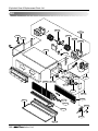
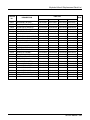
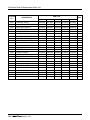
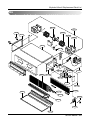
Exploded View & Replacement Parts List ..........................................303
2
Safety Precautions
Safety Precautions
To prevent injury to the user or other people and property damage, the following instructions must
be followed.
■ Incorrect operation due to ignoring instruction will cause harm or damage. The seriousness is
classified by the following indications.
This symbol indicates the possibility of death or serious injury.
This symbol indicates the possibility of injury or damage to properties only.
■ Meanings of symbols used in this manual are as shown below.
Be sure not to do.
Be sure to follow the instruction.
■ Installation
Have all electric work done by a licensed
electrician according to "Electric Facility
Engineering Standard" and "Interior Wire
Regulations" and the instructions given in
this manual and always use a special circuit.
• If the power source capacity is inadequate or
electric work is performed improperly, electric
shock or fire may result.
Always ground the product.
• There is risk of fire or electric shock.
Ask the dealer or an authorized technician to
install the air conditioner.
• Improper installation by the user may result in
water leakage, electric shock, or fire.
Always intstall a dedicated circuit and breaker.
• Improper wiring or installation may cause fire or
electric shock.
Service Manual 3
Safety Precautions
For re-installation of the installed product,
always contact a dealer or an Authorized
Service Center.
Do not install, remove, or re-install the unit
by yourself (customer).
• There is risk of fire, electric shock, explosion, or
injury.
• There is risk of fire, electric shock, explosion, or
injury.
Do not store or use flammable gas or
combustibles near the air conditioner.
• There is risk of fire or failure of product.
Use the correctly rated breaker or fuse.
• There is risk of fire or electric shock.
Gasolin
Prepare for strong wind or earthquake and
install the unit at the specified place.
• Improper installation may cause the unit to topple and result in injury.
When installing and moving the air conditioner to another site, do not charge it with a
different refrigerant from the refrigerant
specified on the unit.
• If a different refrigerant or air is mixed with the
original refrigerant, the refrigerant cycle may
malfunction and the unit may be damaged.
4
Do not install the product on a defective
installation stand.
• It may cause injury, accident, or damage to the
product.
Do not reconstruct to change the settings of
the protection devices.
• If the pressure switch, thermal switch, or other
protection device is shorted and operated
forcibly, or parts other than
those specified by LGE are
used, fire or explosion may
result.
Safety Precautions
Ventilate before operating air conditioner
when gas leaked out.
• It may cause explosion, fire, and burn.
Securely install the cover of control box and
the panel.
• If the cover and panel are not installed securely,
dust or water may enter the outdoor unit and fire
or electric shock may result.
If the air conditioner is installed in a small room, measures must be taken to prevent the
refrigerant concentration from exceeding the safety limit when the refrigerant leaks.
• Consult the dealer regarding the appropriate measures to prevent the safety limit from being exceeded. Should the refrigerant leak and cause the safety limit to be exceeded, harzards due to lack of oxygen in the room could result.
■ Operation
Do not damage or use an unspecified power
cord.
• There is risk of fire, electric shock, explosion, or
injury.
Be cautious that water could not enter the
product.
• There is risk of fire, electric shock, or product
damage.
Use a dedicated outlet for this appliance.
• There is risk of fire or electrical shock.
Do not touch the power switch with wet
hands.
• There is risk of fire, electric shock, explosion, or
injury.
Service Manual 5
Safety Precautions
When the product is soaked (flooded or
submerged), contact an Authorized Service
Center.
• There is risk of fire or electric shock.
Be cautious not to touch the sharp edges
when installing.
• It may cause injury.
Take care to ensure that nobody could step
on or fall onto the outdoor unit.
Do not open the inlet grill of the product during operation. (Do not touch the electrostatic
filter, if the unit is so equipped.)
• This could result in personal injury and product
damage.
• There is risk of physical injury, electric shock, or
product failure.
■ Installation
Always check for gas (refrigerant) leakage
after installation or repair of product.
• Low refrigerant levels may cause failure of
product.
Keep level even when installing the product.
• To avoid vibration or water leakage.
90˚
6
Do not install the product where the noise or
hot air from the outdoor unit could damage
the neighborhoods.
• It may cause a problem for your neighbors.
Do not install the unit where combustible gas
may leak.
• If the gas leaks and accumulates around the
unit, an explosion may result.
Gasolin
Safety Precautions
Use power cables of sufficient current
carrying capacity and rating.
• Cables that are too small may leak, generate
heat, and cause a fire.
Keep the unit away from children. The heat
exchanger is very sharp.
• It can cause the injury, such as cutting the finger.
Also the damaged fin may result in degradation
of capacity.
Do not use the product for special purposes,
such as preserving foods, works of art, etc. It
is a consumer air conditioner, not a precision
refrigeration system.
• There is risk of damage or loss of property.
When installting the unit in a hospital, communication station, or similar place, provide
sufficient protection against noise.
• The inverter equipment, private power generator,
high-frequency medical equipment, or radio communication equipment may cause the air conditioner to operate erroneously, or fail to operate. On the
other hand, the air conditioner may affect such
equipment by creating noise that disturbs medical
treatment or image broadcasting.
Do not install the product where it is exposed to sea wind (salt spray) directly.
• It may cause corrosion on the product. Corrosion, particularly on the condenser and evaporator fins,
could cause product malfunction or inefficient operation.
Service Manual 7
Safety Precautions
■ Operation
Do not use the air conditioner in special
environments.
• Oil, steam, sulfuric smoke, etc. can significantly
reduce the performance of the air conditioner or
damage its parts.
Make the connections securely so that the
outside force of the cablemay not be applied
to the terminals.
• Inadequate connection and fastening may generate heat and cause a fire.
Do not block the inlet or outlet.
• It may cause failure of appliance or accident.
Be sure the installation area does not deteriorate with age.
• If the base collapses, the air conditioner could
fall with it, causing property damage, product
failure, or personal injury.
Install and insulate the drain hose to ensure that water is drained away properly based on the
installation manual.
• A bad connection may cause water leakage.
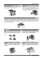
Be very careful about product transportation.
• Only one person should not carry the product if it weighs more
than 20 kg.
• Some products use PP bands for packaging. Do not use any PP
bands for a means of transportation. It is dangerous.
• Do not touch the heat exchanger fins. Doing so may cut your fingers.
• When transporting the Outdoor Unit, suspending it at the specified
positions on the unit base. Also support the Outdoor Unit at four
points so that it cannot slip sideways.
8
Safety Precautions
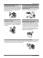
Safely dispose of the packing materials.
• Packing materials, such as nails and other metal or
wooden parts, may cause stabs or other injuries.
• Tear apart and throw away plastic packaging bags
so that children may not play with them. If children
play with a plastic bag which was
not torn apart, they face the
risk of suffocation.
Do not touch any of the refrigerant piping
during and after operation.
• It can cause a burn or frostbite.
Do not directly turn off the main power
switch after stopping operation.
• Wait at least 5 minutes before turning off the
main power switch.
Otherwise it may result in
water leakage or other
problems.
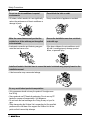
Use a firm stool or ladder when cleaning or
maintaining the air conditioner.
• Be careful and avoid personal injury.
Turn on the power at least 12 hours before
starting operation.(In case of outdoor
temperature 5°C below)
• Starting operation immediately after turning on
the main power switch can result in severe
damage to internal parts. Keep the power switch
turned on during the operational season.
Do not operate the air conditioner with the
panels or guards removed.
• Rotating, hot, or high-voltage parts can cause
injuries.
Auto-addressing should be done in condition of
connecting the power of all indoor and outdoour
units. Auto-addressing should also be done in
case of changing the Indoor Unit board(PCB).
Do not insert hands or other objects through
the air inlet or outlet while the air conditioner
is plugged in.
• There are sharp and moving parts that could
cause personal injury.
Service Manual 9
Part 1
General Information
1. Model Names ................................................................11
1.1 Indoor Unit .............................................................11
1.2 Outdoor Unit ..........................................................11
2. External Appearance.....................................................12
2.1 Indoor Unit .............................................................12
2.2 Outdoor Unit ..........................................................13
3. Combination of Outdoor Units .....................................14
4. Nomenclature.................................................................15
4.1 Indoor Unit ..............................................................15
4.2 Outdoor Unit ...........................................................15
5. Outdoor Units Information............................................16
10
Model Names
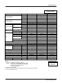
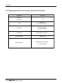
1. Model Names
1.1 Indoor Unit
Category
SR
Wall Mounted
(General)
ART COOL
Capacity(Btu/h(kW))
Chassis
Name
7k
(2.1)
9k
(2.6)
12k
(3.5)
SU
ART COOL
SP
076SU*0 096SU*0
072SU*0 092SU*0
096SP*0
092SP*0
ART COOL Wide SV
1 Way
Ceiling
Cassette
TC
076TCA0 096TCA0
072TCA0 092TCA0
TE
4 Way
186STA0
182STA0
126SU*0 186S3*0
122SU*0 122S3*0
126SP*0
122SP*0
126SV*0 186SV*0
122SV*0 182SV*0
126TCA0
122TCA0
126TEA0 186TEA0
122TEA0 182TEA0
BH
High Static
24k
(7.0)
28k
36k
38k
42k 4 8 k
(8.2) (10.6) (11.1) (12.3) (14.1)
246S3*0
242S3*0
216TDA0
212TDA0
186BHA0 216BHA0
182BHA0 212BHA0
TD
Ceiling
Concealed
Duct
21K
(6.2)
076SRA0 096SRA0 126SRA0
072SRA0 092SRA0 122SRA0
ST
Deluxe
18k
(5.3)
BG
246TDA0 286TDA0 366TDA0
242TDA0 282TDA0 362TDA0
246BHA0
242BHA0
286BGA0 366BGA0
282BGA0 362BGA0
386TDA0 426TDA0
382TDA0 422TDA0
386BGA0 426BGA0
382BGA0 422BGA0
486BEA0
482BEA0
BE
Low Static
Ceiling & Floor Convertible
BT
486TDA
482TDA0
076BTG0 096BTG0 126BTG0
072BTG0 092BTG0 122BTG0
186VBA0
182VBA0
VB
Cooling Only
LRNV
Heat Pump
LRNN
1Ø, 220 ~ 240V, 50Hz
6
1Ø, 220V, 60Hz
2
246VBA0
242VBA0
These are model names of the basic function
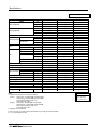
1.2 Outdoor Unit
Power Supply
3Ø, 380 ~ 415V, 50Hz
3Ø, 380V, 60Hz
3Ø, 220V, 60Hz
5HP
508T0
509T0
6HP
608T0
609T0
8HP
808T0
809T0
80BT0
10HP
1008T0
1009T0
100BT0
12HP
1208T0
1209T0
120BT0
Power Supply
24HP
26HP
28HP
30HP
32HP
14HP
16HP
18HP
20HP
22HP
1408T0 1608TS0 1808TS0 2008TS0 2208TS0
1409T0 1609TS0 1809TS0 2009TS0 2209TS0
34HP
36HP
38HP
40HP
3Ø, 380 ~ 415V, 50Hz
2408TS0 2608TR0 2808TR0 3008TR0 3208TR0 3408TR0 3608TR0 3808TR0 4008TR0
3Ø, 380V, 60Hz
2409TS0 2609TS0 2809TR0 3009TR0 3209TR0 3409TR0 3609TR0 3809TR0 4009TR0
Cooling Only
LRUV
Heat Pump
LRUN
Service Manual 11
External Appearance
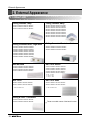
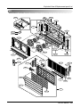
2. External Appearance
2.1 Indoor Unit
Ceiling Cassette- 1Way
Ceiling Cassette- 4Way
LRNV076TCA0 / LRNN076TCA0 / LRNV072TCA0 / LRNN072TCA0
LRNV096TCA0 / LRNN096TCA0 / LRNV092TCA0 / LRNN092TCA0
LRNV126TCA0 / LRNN126TCA0 / LRNV122TCA0 / LRNN122TCA0
LRNV126TEA0 / LRNN126TEA0 / LRNV122TEA0 / LRNN122TEA0
LRNV186TEA0 / LRNN186TEA0 / LRNV182TEA0 / LRNN182TEA0
LRNV216TDA0 / LRNN216TDA0 / LRNV212TDA0 / LRNN212TDA0
LRNV246TDA0 / LRNN246TDA0 / LRNV242TDA0 / LRNN242TDA0
LRNV286TDA0 / LRNN286TDA0 / LRNV282TDA0 / LRNN282TDA0
LRNV366TDA0 / LRNN366TDA0 / LRNV362TDA0 / LRNN362TDA0
LRNV386TDA0 / LRNN386TDA0 / LRNV382TDA0 / LRNN382TDA0
LRNV426TDA0 / LRNN426TDA0 / LRNV422TDA0 / LRNN422TDA0
LRNV486TDA0 / LRNN486TDA0 / LRNV482TDA0 / LRNN482TDA0
Ceiling Concealed Duct - High Static
Ceiling Concealed Duct - Low Static
LRNV186BHA0 / LRNN186BHA0 / LRNV182BHA0 / LRNN182BHA0
LRNV216BHA0 / LRNN216BHA0 / LRNV212BHA0 / LRNN212BHA0
LRNV246BHA0 / LRNN246BHA0 / LRNV242BHA0 / LRNN242BHA0
LRNV286BGA0 / LRNN286BGA0 / LRNV282BGA0 / LRNN282BGA0
LRNV366BGA0 / LRNN366BGA0 / LRNV362BGA0 / LRNN362BGA0
LRNV386BGA0 / LRNN386BGA0 / LRNV382BGA0 / LRNN382BGA0
LRNV426BGA0 / LRNN426BGA0 / LRNV422BGA0 / LRNN422BGA0
LRNV486BEA0 / LRNN486BEA0 / LRNV482BEA0 / LRNN482BEA0
LRNV076BTG0 / LRNN076BTG0 / LRNV072BTG0 / LRNN072BTG0
LRNV096BTG0 / LRNN096BTG0 / LRNV092BTG0 / LRNN092BTG0
LRNV126BTG0 / LRNN126BTG0 / LRNV122BTG0 / LRNN122BTG0
Wall Mounted
ART COOL Deluxe
LRNV076SRA0 / LRNN076SRA0 / LRNV072SRA0 / LRNN072SRA0
LRNV096SRA0 / LRNN096SRA0 / LRNV092SRA0 / LRNN092SRA0
LRNV126SRA0 / LRNN126SRA0 / LRNV122SRA0 / LRNN122SRA0
LRNV186STA0 / LRNN186STA0 / LRNV182STA0 / LRNN182STA0
LRNV076SU*0 / LRNN076SU*0 / LRNV072SU*0 / LRNN072SU*0
LRNV096SU*0 / LRNN096SU*0 / LRNV092SU*0 / LRNN092SU*0
LRNV126SU*0 / LRNN126SU*0 / LRNV122SU*0 / LRNN122SU*0
LRNV186S3*0 / LRNN186S3*0 / LRNV182S3*0 / LRNN182S3*0
LRNV246S3*0 / LRNN246S3*0 / LRNV24S3*0 / LRNN242S3*0
* B : Blue
M : Metal
D : Wood R : Mirror
C : Cherry W : White
ART COOL
ART COOL Wide
LRNV096SP*0 / LRNN096SP*0 / LRNV092SP*0 / LRNN092SP*0
LRNV126SP*0 / LRNN126SP*0 / LRNV122SP*0 / LRNN122SP*0
LRNV126SV*0 / LRNN126SV*0 / LRNV122SV*0 / LRNN122SV*0
LRNV186SV*0 / LRNN186SV*0 / LRNV182SV*0 / LRNN182SV*0
* B : Blue M : Metal D : Wood
* B : Blue M : Metal D : Wood
Ceiling & Floor - Convertible
LRNV186VBA0 / LRNN186VBA0 / LRNV182VBA0 / LRNN182VBA0
LRNV246VBA0 / LRNN246VBA0 / LRNV242VBA0 / LRNN242VBA0
12
These are model names of the basic function.
External Appearance
2.2 Outdoor Unit
LRUV508T0 / LRUN508T0 / LRUV509T0 / LRUN509T0
LRUV608T0 / LRUN608T0 / LRUV609T0 / LRUN609T0
LRUV808T0 / LRUV809T0
5, 6, 8HP
LRUN808T0 / LRUN809T0 / LRUV80BT0 / LRUN80BT0
LRUV1008T0 / LRUN1008T0 / LRUV1009T0 / LRUN1009T0 / LRUV100BT0 / LRUN100BT0
LRUV1208T0 / LRUN1208T0 / LRUV1209T0 / LRUN1209T0 / LRUV120BT0 / LRUN120BT0
LRUV1408T0 / LRUN1408T0 / LRUV1409T0 / LRUN1409T0
8, 10, 12, 14HP
LRUV1608TS0 / LRUN1608TS0 / LRUV1609TS0 / LRUN1609TS0
LRUV1808TS0 / LRUN1808TS0 / LRUV1809TS0 / LRUN1809TS0
LRUV2008TS0 / LRUN2008TS0 / LRUV2009TS0 / LRUN2009TS0
LRUV2208TS0 / LRUN2208TS0 / LRUV2209TS0 / LRUN2209TS0
LRUV2408TS0 / LRUN2408TS0 / LRUV2409TS0 / LRUN2409TS0
LRUV2609TS0 / LRUN2609TS0
16, 18, 20, 22, 24, 26HP
LRUV2608TR0 / LRUN2608TR0
LRUV2808TR0 / LRUN2808TR0 / LRUV2809TR0 / LRUN2809TR0
LRUV3008TR0 / LRUN3008TR0 / LRUV3009TR0 / LRUN3009TR0
LRUV3208TR0 / LRUN3208TR0 / LRUV3209TR0 / LRUN3209TR0
LRUV3408TR0 / LRUN3408TR0 / LRUV3409TR0 / LRUN3409TR0
LRUV3608TR0 / LRUN3608TR0 / LRUV3609TR0 / LRUN3609TR0
LRUV3808TR0 / LRUN3808TR0 / LRUV3809TR0 / LRUN3809TR0
LRUV4008TR0 / LRUN4008TR0 / LRUV4009TR0 / LRUN4009TR0
26, 28, 30, 32, 34, 36, 38, 40HP
Service Manual 13
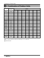
Combination of Outdoor Units
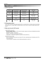
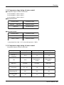
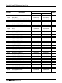
3. Combination of Outdoor Units
System Capacity Number of Units
50Hz(60Hz)
Module
5
6
8
10
12
5HP
1(1)
6HP
1(1)
8HP
1(1)
10HP
1(1)
12HP
1(1)
14HP
1(1)
16HP
2(2)
2
18HP
2(2)
1
20HP
2(2)
2
22HP
2(2)
1
24HP
2(2)
26HP
3(2)
2
1
28HP
3(3)
1
2
30HP
3(3)
3
32HP
3(3)
2
34HP
3(3)
2
36HP
3(3)
3
38HP
3(3)
2
40HP
3(3)
2
14
16
1
1
1
1
1
1
1
1
2
■ Up to a maximum 40HP are realized by combining 8, 10, 12, 14 and 16HP
■ * :3Ø, 380V, 60Hz
14
*(1)
*(1)
1
1
1
1
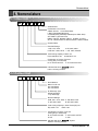
Nomenclature
4. Nomenclature
4.1 Indoor Unit
LRN
N
07
6
SR
A
0
Serial Number
Combinations of functions
A:Basic function G:Low Static Motor
L:Nano Plasma(Wall Mounted)
C:Plasma(Ceiling Cassette) Q:Plasma(Low Static Duct)
ART COOL Type Panel Color
B:Blue D:Wood M:Metal R:Mirror W:White C:Cherry
SP, SV- J:Blue+Plasma K:Wood+Plasma L:Metal +Plasma
Chassis Name
Electrical Ratings
1:1Ø, 115V, 60Hz
2: 1Ø, 220V, 60Hz
6:1Ø, 220 ~ 240V, 50Hz 7: 1Ø, 100V, 50/60Hz
Total Cooling Capacity in Btu/h unit
EX) 5,000 Btu/h➞'05' 18,000 Btu/h➞'18'
Combination of Inverter Type and
Cooling Only or Heat Pump
N: AC Inverter and H/P V: AC Inverter and C/O
Indicates that this is
Indoor Unit using the R22
System
4.2 Outdoor Unit
LRU
N
100
8
T
S
0
Serial Number
Multi V PLUS unit
S:2 Units Series
R:3 Units Series
Air Discharge Type
S:Side Discharge
T:Top Discharge
Electrical Ratings
8:3Ø, 380 ~ 415V, 50Hz 9: 3Ø, 380V, 60Hz
A: 3Ø, 220V, 50Hz
B: 3Ø, 220V, 60Hz
Total Cooling Capacity in Horse Power(HP) unit
EX) 4.5HP➞'45'
10HP➞'100'
Combination of Inverter Type and
Cooling Only or Heat Pump
N: AC Inverter and H/P V: AC Inverter and C/O
H: H/P
C: C/O
Indicates that this is
Outdoor Unit using the R22
System
Service Manual 15
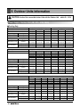
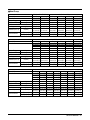
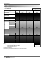
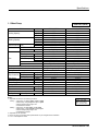
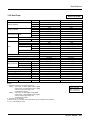
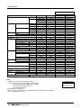
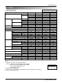
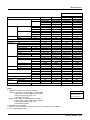
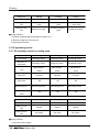
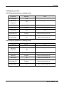
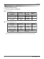
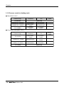
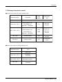
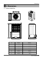
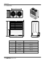
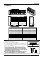
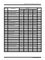
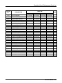
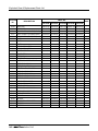
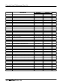
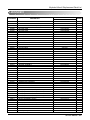
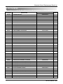
5. Outdoor Units Information
CAUTION: A ratio of the connectable Indoor Units with the Outdoor Unit : within 50 ~ 130%
Power Supply: Outdoor Unit (3Ø, 380 ~ 415V, 50Hz)
■ Cooling Only
Unit
System(HP)
Model
Product Charge
kg
CF(Correction Factor)
kg
Max. Connectable No. of Indoor Units
Net Weight
kg(lbs)
1 Outdoor Unit(Half size)
1 Outdoor Unit
5
6
8
10
12
14
LRUV508T0
LRUV608T0
LRUV808T0
LRUV1008T0 LRUV1208T0 LRUV1408T0
5
5
6
10
10
10
0
0
0
-1
-1
-1
6
8
13
16
16
16
150(330.7)
150(330.7)
150(330.7)
300(661.4)
300(661.4)
300(661.4)
806 x 1555 x 730 806 x 1555 x 730 806 x 1555 x 730 1280 x 1555 x 730 1280 x 1555 x 730 1280 x 1555 x 730
Dimensions (W x H x D)
mm(inch)
(31.7 x 61.2 x 28.7) (31.7 x 61.2 x 28.7) (31.7 x 61.2 x 28.7) (50.4 x 61.2 x 28.7) (50.4 x 61.2 x 28.7) (50.4 x 61.2 x 28.7)
Liquid Pipes(mm(inch)) Ø9.52(3/8) Ø9.52(3/8)
Ø12.7(1/2)
Ø12.7(1/2)
Ø12.7(1/2) Ø12.7(1/2)
Pipe Connections
1
1
Gas Pipes(mm(inch)) Ø19.05(3/4) Ø22.2(7/8) Ø28.58(1 /8) Ø28.58(1 /8) Ø28.58(11/8) Ø28.58(11/8)
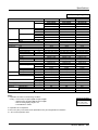
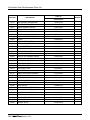
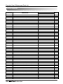
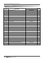
Unit
System(HP)
Model
2 Outdoor Units
3 Outdoor Units
16
18
20
22
24
26
LRUV1608TS0 LRUV1808TS0 LRUV2008TS0 LRUV2208TS0 LRUV2408TS0 LRUV2608TR0
LRUV808TS0 LRUV1008TS0 LRUV1008TS0 LRUV1208TS0 LRUV1208TS0 LRUV1008TR0
LRUC808TS0 LRUC808TS0 LRUC1008TS0 LRUC1008TS0 LRUC1208TS0 LRUC808TR0
LRUC808TR0
Product Charge
kg
10 x 2
10 x 2
10 x 2
10 x 2
10 x 2
10 x 3
CF(Correction Factor)
kg
-2
-2
-2
-2
-2
0
Max. Connectable No. of Indoor Units
20
20
20
22
24
26
Net Weight
kg(lbs)
300(661.4) x 2 300(661.4) x 2 300(661.4) x 2 300(661.4) x 2 300(661.4) x 2 300(661.4) x 3
(1280 x 1555 x 730) x 2 (1280 x 1555 x 730) x 2 (1280 x 1555 x 730) x 2 (1280 x 1555 x 730) x 2 (1280 x 1555 x 730) x 2 (1280 x 1555 x 730) x 3
Dimensions (W x H x D)
mm(inch)
((50.4 x 61.2 x 28.7) x 2) ((50.4 x 61.2 x 28.7) x 2) ((50.4 x 61.2 x 28.7) x 2) ((50.4 x 61.2 x 28.7) x 2) ((50.4 x 61.2 x 28.7) x 2) ((50.4 x 61.2 x 28.7) x 3)
Liquid Pipes(mm(inch)) Ø19.05(3/4) Ø19.05(3/4) Ø19.05(3/4) Ø19.05(3/4) Ø19.05(3/4) Ø22.2(7/8)
Pipe Connections
Gas Pipes(mm(inch)) Ø38.1(11/2) Ø38.1(11/2) Ø38.1(11/2) Ø38.1(11/2) Ø38.1(11/2) Ø44.5(13/4)
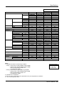
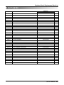
Unit
System(HP)
Model
28
LRUV2808TR0
LRUV808TR0
LRUC1008TR0
LRUC1008TR0
Product Charge
kg
10 x 3
0
CF(Correction Factor)
kg
Max. Connectable No. of Indoor Units
32
Net Weight
kg(lbs)
300(661.4) x 3
(1280 x 1555 x 730) x 3
Dimensions (W x H x D)
mm(inch)
((50.4 x 61.2 x 28.7) x 3)
Liquid Pipes(mm(inch)) Ø22.2(7/8)
Pipe Connections
Gas Pipes(mm(inch)) Ø44.5(13/4)
16
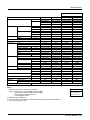
3 Outdoor Units
30
32
34
36
LRUV3008TR0 LRUV3208TR0 LRUV3408TR0 LRUV3608TR0
LRUV1008TR0 LRUV1208TR0 LRUV1408TR0 LRUV1208TR0
LRUC1008TR0 LRUC1008TR0 LRUC1008TR0 LRUC1208TR0
LRUC1008TR0 LRUC1008TR0 LRUC1008TR0 LRUC1208TR0
10 x 3
10 x 3
10 x 3
10 x 3
0
0
1
1
32
32
34
36
300(661.4) x 3 300(661.4) x 3 300(661.4) x 3 300(661.4) x 3
(1280 x 1555 x 730) x 3 (1280 x 1555 x 730) x 3 (1280 x 1555 x 730) x 3 (1280 x 1555 x 730) x 3
((50.4 x 61.2 x 28.7) x 3) ((50.4 x 61.2 x 28.7) x 3) ((50.4 x 61.2 x 28.7) x 3) ((50.4 x 61.2 x 28.7) x 3)
Ø22.2(7/8) Ø22.2(7/8) Ø22.2(7/8) Ø22.2(7/8)
Ø44.5(13/4) Ø44.5(13/4) Ø44.5(13/4) Ø44.5(13/4)
38
LRUV3808TR0
LRUV1408TR0
LRUC1208TR0
LRUC1208TR0
10 x 3
2
38
300(661.4) x 3
(1280 x 1555 x 730) x 3
((50.4 x 61.2 x 28.7) x 3)
Ø22.2(7/8)
Ø44.5(13/4)
40
LRUV4008TR0
LRUV1608TR0
LRUC1208TR0
LRUC1208TR0
10 x 3
2
40
300(661.4) x 3
(1280 x 1555 x 730) x 3
((50.4 x 61.2 x 28.7) x 3)
Ø22.2(7/8)
Ø44.5(13/4)
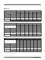
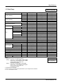
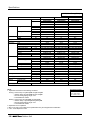
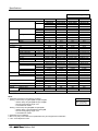
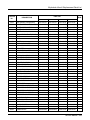
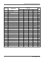
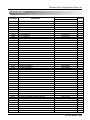
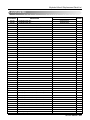
■ Heat Pump
Unit
System(HP)
Model
Product Charge
kg
CF(Correction Factor)
kg
Max. Connectable No. of Indoor Units
Net Weight
kg(lbs)
1 Outdoor Unit(Half size)
1 Outdoor Unit
5
6
8
10
12
LRUN508T0 LRUN608T0 LRUN808T0 LRUN1008T0 LRUN1208T0
5
5
10
10
10
0
0
-1
-1
-1
6
8
13
16
16
150(330.7) 150(330.7) 300(661.4) 300(661.4) 300(661.4)
806 x 1555 x 730 806 x 1555 x 730 1280 x 1555 x 730 1280 x 1555 x 730 1280 x 1555 x 730
Dimensions (W x H x D)
mm(inch)
(31.7 x 61.2 x 28.7) (31.7 x 61.2 x 28.7) (50.4 x 61.2 x 28.7) (50.4 x 61.2 x 28.7) (50.4 x 61.2 x 28.7)
Liquid Pipes(mm(inch)) Ø9.52(3/8) Ø9.52(3/8)
Ø12.7(1/2)
Ø12.7(1/2)
Ø12.7(1/2)
Pipe Connections
Gas Pipes(mm(inch)) Ø19.05(3/4) Ø22.2(7/8) Ø28.58(11/8) Ø28.58(11/8) Ø28.58(11/8)
14
LRUN1408T0
10
-1
16
300(661.4)
1280 x 1555 x 730
(50.4 x 61.2 x 28.7)
Ø12.7(1/2)
Ø28.58(11/8)
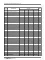
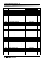
Unit
System(HP)
Model
2 Outdoor Units
3 Outdoor Units
16
18
20
22
24
26
LRUN1608TS0 LRUN1808TS0 LRUN2008TS0 LRUN2208TS0 LRUN2408TS0 LRUN2608TR0
LRUN808TS0 LRUN1008TS0 LRUN1008TS0 LRUN1208TS0 LRUN1208TS0 LRUN1008TR0
LRUH808TS0 LRUH808TS0 LRUH1008TS0 LRUH1008TS0 LRUH1208TS0 LRUH808TR0
LRUH808TR0
Product Charge
kg
10 x 2
10 x 2
10 x 2
10 x 2
10 x 2
10 x 3
CF(Correction Factor)
kg
-2
-2
-2
-2
-2
0
Max. Connectable No. of Indoor Units
20
20
20
22
24
26
Net Weight
kg(lbs)
300(661.4) x 2 300(661.4) x 2 300(661.4) x 2 300(661.4) x 2 300(661.4) x 2 300(661.4) x 3
(1280 x 1555 x 730) x 2 (1280 x 1555 x 730) x 2 (1280 x 1555 x 730) x 2 (1280 x 1555 x 730) x 2 (1280 x 1555 x 730) x 2 (1280 x 1555 x 730) x 3
Dimensions (W x H x D)
mm(inch)
((50.4 x 61.2 x 28.7) x 2) ((50.4 x 61.2 x 28.7) x 2) ((50.4 x 61.2 x 28.7) x 2) ((50.4 x 61.2 x 28.7) x 2) ((50.4 x 61.2 x 28.7) x 2) ((50.4 x 61.2 x 28.7) x 3)
Liquid Pipes(mm(inch)) Ø19.05(3/4) Ø19.05(3/4) Ø19.05(3/4) Ø19.05(3/4) Ø19.05(3/4) Ø22.2(7/8)
Pipe Connections
Gas Pipes(mm(inch)) Ø38.1(11/2) Ø38.1(11/2) Ø38.1(11/2) Ø38.1(11/2) Ø38.1(11/2) Ø44.5(13/4)
Unit
System(HP)
Model
28
LRUN2808TR0
LRUN808TR0
LRUH1008TR0
LRUH1008TR0
Product Charge
kg
10 x 3
CF(Correction Factor)
kg
0
Max. Connectable No. of Indoor Units
32
Net Weight
kg(lbs)
300(661.4) x 3
(1280 x 1555 x 730) x 3
Dimensions (W x H x D)
mm(inch)
((50.4 x 61.2 x 28.7) x 3)
Liquid Pipes(mm(inch)) Ø22.2(7/8)
Pipe Connections
Gas Pipes(mm(inch)) Ø44.5(13/4)
30
LRUN3008TR0
LRUN1008TR0
LRUH1008TR0
LRUH1008TR0
10 x 3
0
32
300(661.4) x 3
(1280 x 1555 x 730) x 3
((50.4 x 61.2 x 28.7) x 3)
Ø22.2(7/8)
Ø44.5(13/4)
3 Outdoor Units
32
34
36
LRUN3208TR0 LRUN3408TR0 LRUN3608TR0
LRUN1208TR0 LRUN1408TR0 LRUN1208TR0
LRUH1008TR0 LRUH1008TR0 LRUH1208TR0
LRUH1008TR0 LRUH1008TR0 LRUH1208TR0
10 x 3
10 x 3
10 x 3
0
1
1
32
34
36
300(661.4) x 3 300(661.4) x 3 300(661.4) x 3
(1280 x 1555 x 730) x 3 (1280 x 1555 x 730) x 3 (1280 x 1555 x 730) x 3
((50.4 x 61.2 x 28.7) x 3) ((50.4 x 61.2 x 28.7) x 3) ((50.4 x 61.2 x 28.7) x 3)
Ø22.2(7/8) Ø22.2(7/8) Ø22.2(7/8)
Ø44.5(13/4) Ø44.5(13/4) Ø44.5(13/4)
38
LRUN3808TR0
LRUN1408TR0
LRUH1208TR0
LRUH1208TR0
10 x 3
2
38
300(661.4) x 3
(1280 x 1555 x 730) x 3
((50.4 x 61.2 x 28.7) x 3)
Ø22.2(7/8)
Ø44.5(13/4)
40
LRUN4008TR0
LRUN1608TR0
LRUH1208TR0
LRUH1208TR0
10 x 3
2
40
300(661.4) x 3
(1280 x 1555 x 730) x 3
((50.4 x 61.2 x 28.7) x 3)
Ø22.2(7/8)
Ø44.5(13/4)
Service Manual 17
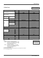
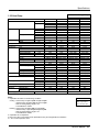
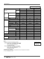
Power Supply: Outdoor Unit (3Ø, 380V, 60Hz)
■ Cooling Only
Unit
System(HP)
Model
Product Charge
kg
CF(Correction Factor)
kg
Max. Connectable No. of Indoor Units
Net Weight
kg(lbs)
1 Outdoor Unit(Half size)
1 Outdoor Unit
5
6
8
10
12
14
LRUV509T0 LRUV609T0 LRUV809T0 LRUV1009T0 LRUV1209T0 LRUV1409T0
5
5
6
10
10
10
0
0
0
-1
-1
-1
6
8
13
16
16
16
150(330.7)
150(330.7)
150(330.7)
300(661.4)
300(661.4)
300(661.4)
806 x 1555 x 730 806 x 1555 x 730 806 x 1555 x 730 1280 x 1555 x 730 1280 x 1555 x 730 1280 x 1555 x 730
Dimensions (W x H x D)
mm(inch)
(31.7 x 61.2 x 28.7) (31.7 x 61.2 x 28.7) (31.7 x 61.2 x 28.7) (50.4 x 61.2 x 28.7) (50.4 x 61.2 x 28.7) (50.4 x 61.2 x 28.7)
Liquid Pipes(mm(inch)) Ø9.52(3/8) Ø9.52(3/8)
Ø12.7(1/2)
Ø12.7(1/2)
Ø12.7(1/2) Ø12.7(1/2)
Pipe Connections
1
1
Gas Pipes(mm(inch)) Ø19.05(3/4) Ø22.2(7/8) Ø28.58(1 /8) Ø28.58(1 /8) Ø28.58(11/8) Ø28.58(11/8)
Unit
System(HP)
Model
16
LRUV1609TS0
LRUV809TS0
LRUC809TS0
Product Charge
kg
10 x 2
CF(Correction Factor)
kg
-2
Max. Connectable No. of Indoor Units
20
Net Weight
kg(lbs)
300(661.4) x 2
(1280 x 1555 x 730) x 2
Dimensions (W x H x D)
mm(inch)
((50.4 x 61.2 x 28.7) x 2)
Liquid Pipes(mm(inch)) Ø19.05(3/4)
Pipe Connections
Gas Pipes(mm(inch)) Ø38.1(11/2)
Unit
System(HP)
Model
28
LRUV2809TR0
LRUV809TR0
LRUC1009TR0
LRUC1009TR0
Product Charge
kg
10 x 3
CF(Correction Factor)
kg
0
Max. Connectable No. of Indoor Units
32
Net Weight
kg(lbs)
300(661.4) x 3
(1280 x 1555 x 730) x 3
Dimensions (W x H x D)
mm(inch)
((50.4 x 61.2 x 28.7) x 3)
Liquid Pipes(mm(inch)) Ø22.2(7/8)
Pipe Connections
Gas Pipes(mm(inch)) Ø44.5(13/4)
18
18
LRUV1809TS0
LRUV1009TS0
LRUC809TS0
10 x 2
-2
20
300(661.4) x 2
(1280 x 1555 x 730) x 2
((50.4 x 61.2 x 28.7) x 2)
Ø19.05(3/4)
Ø38.1(11/2)
30
LRUV3009TR0
LRUV1009TR0
LRUC1009TR0
LRUC1009TR0
10 x 3
0
32
300(661.4) x 3
(1280 x 1555 x 730) x 3
((50.4 x 61.2 x 28.7) x 3)
Ø22.2(7/8)
Ø44.5(13/4)
2 Outdoor Units
20
22
LRUV2009TS0 LRUV2209TS0
LRUV1009TS0 LRUV1209TS0
LRUC1009TS0 LRUC1009TS0
10 x 2
10 x 2
-2
-2
20
22
300(661.4) x 2 300(661.4) x 2
(1280 x 1555 x 730) x 2 (1280 x 1555 x 730) x 2
((50.4 x 61.2 x 28.7) x 2) ((50.4 x 61.2 x 28.7) x 2)
Ø19.05(3/4) Ø19.05(3/4)
Ø38.1(11/2) Ø38.1(11/2)
24
LRUV2409TS0
LRUV1209TS0
LRUC1209TS0
10 x 2
-2
24
300(661.4) x 2
(1280 x 1555 x 730) x 2
((50.4 x 61.2 x 28.7) x 2)
Ø19.05(3/4)
Ø38.1(11/2)
3 Outdoor Units
32
34
36
LRUV3209TR0 LRUV3409TR0 LRUV3609TR0
LRUV1209TR0 LRUV1409TR0 LRUV1209TR0
LRUC1009TR0 LRUC1009TR0 LRUC1209TR0
LRUC1009TR0 LRUC1009TR0 LRUC1209TR0
10 x 3
10 x 3
10 x 3
0
1
1
32
34
36
300(661.4) x 3 300(661.4) x 3 300(661.4) x 3
(1280 x 1555 x 730) x 3 (1280 x 1555 x 730) x 3 (1280 x 1555 x 730) x 3
((50.4 x 61.2 x 28.7) x 3) ((50.4 x 61.2 x 28.7) x 3) ((50.4 x 61.2 x 28.7) x 3)
Ø22.2(7/8) Ø22.2(7/8) Ø22.2(7/8)
Ø44.5(13/4) Ø44.5(13/4) Ø44.5(13/4)
26
LRUV2609TS0
LRUV1409TS0
LRUC1209TS0
10 x 2
-1
26
300(661.4) x 2
(1280 x 1555 x 730) x 2)
((50.4 x 61.2 x 28.7) x 2)
Ø19.05(3/4)
Ø38.1(11/2)
38
LRUV3809TR0
LRUV1409TR0
LRUC1209TR0
LRUC1209TR0
10 x 3
2
38
300(661.4) x 3
(1280 x 1555 x 730) x 3
((50.4 x 61.2 x 28.7) x 3)
Ø22.2(7/8)
Ø44.5(13/4)
40
LRUV4008TR0
LRUV1609TR0
LRUC1209TR0
LRUC1209TR0
10 x 3
2
40
300(661.4) x 3
(1280 x 1555 x 730) x 3
((50.4 x 61.2 x 28.7) x 3)
Ø22.2(7/8)
Ø44.5(13/4)
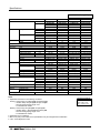
■ Heat Pump
Unit
System(HP)
Model
Product Charge
kg
CF(Correction Factor)
kg
Max. Connectable No. of Indoor Units
Net Weight
kg(lbs)
1 Outdoor Unit(Half size)
5
6
8
LRUN509T0 LRUN609T0 LRUN809T0
5
5
10
0
0
-1
6
8
13
150(330.7)
150(330.7)
300(661.4)
806 x 1555 x 730 806 x 1555 x 730 1280 x 1555 x 730
Dimensions (W x H x D)
mm(inch)
(31.7 x 61.2 x 28.7) (31.7 x 61.2 x 28.7) (50.4 x 61.2 x 28.7)
Liquid Pipes(mm(inch)) Ø9.52(3/8) Ø9.52(3/8)
Ø12.7(1/2)
Pipe Connections
Gas Pipes(mm(inch)) Ø19.05(3/4) Ø22.2(7/8) Ø28.58(11/8)
Unit
System(HP)
Model
16
LRUN1609TS0
LRUN809TS0
LRUH809TS0
Product Charge
kg
10 x 2
CF(Correction Factor)
kg
-2
Max. Connectable No. of Indoor Units
20
300(661.4) x 2
Net Weight
kg(lbs)
(1280 x 1555 x 730) x 2
Dimensions (W x H x D)
mm(inch)
((50.4 x 61.2 x 28.7) x 2)
Liquid Pipes(mm(inch)) Ø19.05(3/4)
Pipe Connections
Gas Pipes(mm(inch)) Ø38.1(11/2)
Unit
System(HP)
Model
28
LRUN2809TR0
LRUN809TR0
LRUH1009TR0
LRUH1009TR0
Product Charge
kg
10 x 3
CF(Correction Factor)
kg
0
Max. Connectable No. of Indoor Units
32
Net Weight
kg(lbs)
300(661.4) x 3
(1280 x 1555 x 730) x 3
Dimensions (W x H x D)
mm(inch)
((50.4 x 61.2 x 28.7) x 3)
Liquid Pipes(mm(inch)) Ø22.2(7/8)
Pipe Connections
Gas Pipes(mm(inch)) Ø44.5(13/4)
18
LRUN1809TS0
LRUN1009TS0
LRUH809TS0
10 x 2
-2
20
300(661.4) x 2
(1280 x 1555 x 730) x 2
((50.4 x 61.2 x 28.7) x 2)
Ø19.05(3/4)
Ø38.1(11/2)
30
LRUN3009TR0
LRUN1009TR0
LRUH1009TR0
LRUH1009TR0
10 x 3
0
32
300(661.4) x 3
(1280 x 1555 x 730) x 3
((50.4 x 61.2 x 28.7) x 3)
Ø22.2(7/8)
Ø44.5(13/4)
1 Outdoor Unit
10
12
LRUN1009T0 LRUN1209T0
10
10
-1
-1
16
16
300(661.4)
300(661.4)
1280 x 1555 x 730 1280 x 1555 x 730
(50.4 x 61.2 x 28.7) (50.4 x 61.2 x 28.7)
Ø12.7(1/2)
Ø12.7(1/2)
Ø28.58(11/8) Ø28.58(11/8)
2 Outdoor Units
20
22
LRUN2009TS0 LRUN2209TS0
LRUN1009TS0 LRUN1209TS0
LRUH1009TS0 LRUH1009TS0
10 x 2
10 x 2
-2
-2
20
22
300(661.4) x 2 300(661.4) x 2
(1280 x 1555 x 730) x 2 (1280 x 1555 x 730)) x 2
((50.4 x 61.2 x 28.7) x 2) ((50.4 x 61.2 x 28.7) x 2)
Ø19.05(3/4) Ø19.05(3/4)
Ø38.1(11/2) Ø38.1(11/2)
24
LRUN2409TS0
LRUN1209TS0
LRUH1209TS0
10 x 2
-2
24
300(661.4) x 2
(1280 x 1555 x 730) x 2
((50.4 x 61.2 x 28.7) x 2)
Ø19.05(3/4)
Ø38.1(11/2)
3 Outdoor Units
32
34
36
LRUN3209TR0 LRUN3409TR0 LRUN3609TR0
LRUN1209TR0 LRUN1409TR0 LRUN1209TR0
LRUH1009TR0 LRUH1009TR0 LRUH1209TR0
LRUH1009TR0 LRUH1009TR0 LRUH1209TR0
10 x 3
10 x 3
10 x 3
0
1
1
32
34
36
300(661.4) x 3 300(661.4) x 3 300(661.4) x 3
(1280 x 1555 x 730) x 3 (1280 x 1555 x 730) x 3 (1280 x 1555 x 730) x 3
((50.4 x 61.2 x 28.7) x 3) ((50.4 x 61.2 x 28.7) x 3) ((50.4 x 61.2 x 28.7) x 3)
Ø22.2(7/8) Ø22.2(7/8) Ø22.2(7/8)
Ø44.5(13/4) Ø44.5(13/4) Ø44.5(13/4)
14
LRUN1409T0
10
-1
16
300(661.4)
1280 x 1555 x 730
(50.4 x 61.2 x 28.7
Ø12.7(1/2)
Ø28.58(11/8)
26
LRUN2609TS0
LRUN1409TS0
LRUH1209TS0
10 x 2
-1
26
300(661.4) x 2
(1280 x 1555 x 730) x 2
((50.4 x 61.2 x 28.7) x 2)
Ø19.05(3/4)
Ø38.1(11/2)
38
LRUN3809TR0
LRUN1409TR0
LRUH1209TR0
LRUH1209TR0
10 x 3
2
38
300(661.4) x 3
(1280 x 1555 x 730) x 3
((50.4 x 61.2 x 28.7) x 3)
Ø22.2(7/8)
Ø44.5(13/4)
40
LRUN4009TR0
LRUN1609TR0
LRUH1209TR0
LRUH1209TR0
10 x 3
2
40
300(661.4) x 3
(1280 x 1555 x 730) x 3
((50.4 x 61.2 x 28.7) x 3)
Ø22.2(7/8)
Ø44.5(13/4)
Service Manual 19
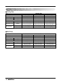
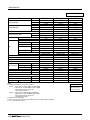
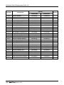
Power Supply: Outdoor Unit (3Ø, 220V, 60Hz)
■ Cooling Only
Unit
System(HP)
Model
Product Charge
kg
CF(Correction Factor)
kg
Max. Connectable No. of Indoor Units
Net Weight
kg(lbs)
Dimensions (W x H x D)
Pipe Connections
mm(inch)
Liquid Pipes(mm(inch))
Gas Pipes(mm(inch))
8
LRUV80BT0
10
-1
13
300(661.4)
1280 x 1555 x 730
(50.4 x 61.2 x 28.7)
Ø12.7(1/2)
Ø28.58(11/8)
1 Outdoor Unit
10
LRUV100BT0
10
-1
16
300(661.4)
1280 x 1555 x 730
(50.4 x 61.2 x 28.7)
Ø12.7(1/2)
Ø28.58(11/8)
12
LRUV120BT0
10
-1
16
300(661.4)
1280 x 1555 x 730
(50.4 x 61.2 x 28.7)
Ø12.7(1/2)
Ø28.58(11/8)
8
LRUN80BT0
10
-1
13
300(661.4)
1280 x 1555 x 730
(50.4 x 61.2 x 28.7)
Ø12.7(1/2)
Ø28.58(11/8)
1 Outdoor Unit
10
LRUN100BT0
10
-1
16
300(661.4)
1280 x 1555 x 730
(50.4 x 61.2 x 28.7)
Ø12.7(1/2)
Ø28.58(11/8)
12
LRUN120BT0
10
-1
16
300(661.4)
1280 x 1555 x 730
(50.4 x 61.2 x 28.7)
Ø12.7(1/2)
Ø28.58(11/8)
■ Heat Pump
Unit
System(HP)
Model
Product Charge
kg
CF(Correction Factor)
kg
Max. Connectable No. of Indoor Units
Net Weight
kg(lbs)
Dimensions (W x H x D)
Pipe Connections
20
mm(inch)
Liquid Pipes(mm(inch))
Gas Pipes(mm(inch))
Indoor Unit
Indoor Units
Service Manual 21
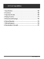
Ceiling Mounted Cassette Type (1Way)
1. Specifications .............................................................................23
2. Functions ....................................................................................27
3. Operation Details........................................................................28
4. Dimensional Drawings ...............................................................30
5. Piping Diagrams .........................................................................31
6. Wiring Diagrams .........................................................................32
22
Indoor Unit
Specifications
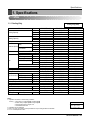
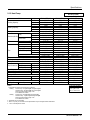
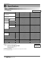
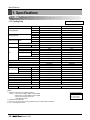
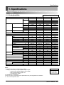
1. Specifications
1.1 50Hz
1.1.1 Cooling Only
Model
Cooling Capacity
Heating Capacity
Cooling Only (50Hz)
Unit
W
kcal/h
Btu/h
W
kcal/h
Btu/h
Casing
Body
Dimensions (W*H*D)
Front Panel
Coil
Fan
Rows x Columns x FPI
Face Area
Type
Motor Output
Running Current
Air Flow Rate(H/M/L)
mm
inch
mm
inch
m2
W
A
cmm
cfm
Drive
Speed control
Temperature Control
Sound Absorbing Thermal Insulation Material
Safety Device
Liquid Side
mm(inch)
Pipe Connections Gas Side
mm(inch)
Drain Pipe(OD)
mm
Net Weight
kg(lbs)
Noise Level(Sound Press, 1.5m, H/M/L) dBA±3
Power Supply
Ø / V / Hz
Refrigerant Control
Power cable
mm2
Transmission cable
mm2
Panel Color
Stuffing Quantity Without S/parts
20/40ft
LRNV076TCA(C)0
2,100
1,806
7,165
Galvanized Steel Plate
860*390*180
33.8*15.3*7.0
1050*480*30
41.3*18.9*1.2
2*12*18
0.17
Cross Flow Fan
14
0.22
6/5/4
212/177/141
Direct
Phase Control
Microprocessor, Thermostat for cooling
Foamed polystrene
Fuse, Thermal Fuse for Fan Motor
Ø6.35(1/4)
Ø12.7(1/2)
32.0
17(37.5)
35/32/29
1 / 220 ~ 240V / 50Hz
LEV
CV2.0 X 3C
CVV-SB 1.25 X 2C
White
263/539
LRNV096TCA(C)0
2,600
2,235
8,871
Galvanized Steel Plate
860*390*180
33.8*15.3*7.0
1050*480*30
41.3*18.9*1.2
2*12*21
0.17
Cross Flow Fan
14
0.22
7/6/5
247/212/177
Direct
Phase Control
Microprocessor, Thermostat for cooling
Foamed polystrene
Fuse, Thermal Fuse for Fan Motor
Ø6.35(1/4)
Ø12.7(1/2)
32.0
17(37.5)
37/34/31
1 / 220 ~ 240V / 50Hz
LEV
CV2.0 X 3C
CVV-SB 1.25 X 2C
White
263/539
Notes:1. Capacities are based on the following conditions:
Cooling • Indoor temp. 27°C[80.6°F]DB/ 19°C[66.2°F]WB
• Outdoor temp. 35°C[95°F]DB/ 24°C[75.2°F]WB
• Interconnecting Piping Length 7.5m
• Level Difference of Zero
2. Capacities are net capacities
3. Due to our policy of innovation some specifications may be changed without notification
4. L.E.V.: Linear Expansion Valve
LRNV126TCA(C)0
3,500
3,009
11,942
Galvanized Steel Plate
860*390*180
33.8*15.3*7.0
1050*480*30
41.3*18.9*1.2
2*12*21
0.17
Cross Flow Fan
14
0.22
10/9/8
353/318/283
Direct
Phase Control
Microprocessor, Thermostat for cooling
Foamed polystrene
Fuse, Thermal Fuse for Fan Motor
Ø6.35(1/4)
Ø12.7(1/2)
32.0
17(37.5)
39/36/35
1 / 220 ~ 240V / 50Hz
LEV
CV2.0 X 3C
CVV-SB 1.25 X 2C
White
263/539
Conversion Formula
Kcal/h= kW x 860
Btu/h = kW x 3412
cfm = m3/min x 35.3
Service Manual 23
Specifications
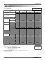
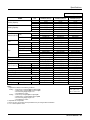
2.1.2 Heat Pump
Heat Pump (50Hz)
Model
Cooling Capacity
Heating Capacity
Unit
W
kcal/h
Btu/h
W
kcal/h
Btu/h
Casing
Body
Dimensions (W*H*D)
Front Panel
Coil
Fan
Rows x Columns x FPI
Face Area
Type
Motor Output
Running Current
Air Flow Rate(H/M/L)
mm
inch
mm
inch
m2
W
A
cmm
cfm
Drive
Speed control
Temperature Control
Sound Absorbing Thermal Insulation Material
Safety Device
Liquid Side
mm(inch)
Pipe Connections Gas Side
mm(inch)
Drain Pipe(OD)
mm
Net Weight
kg(lbs)
Noise Level(Sound Press, 1.5m, H/M/L) dBA±3
Power Supply
Ø / V / Hz
Refrigerant Control
Power cable
mm2
Transmission cable
mm2
Panel Color
Stuffing Quantity Without S/parts
20/40ft
LRNN076TCA(C)0
LRNN096TCA(C)0
LRNN126TCA(C)0
2,100
2,600
3,500
1,806
2,235
3,009
7,165
8,871
11,942
2,363
2,925
3,938
2,031
2,515
3,385
8,061
9,980
13,435
Galvanized Steel Plate Galvanized Steel Plate Galvanized Steel Plate
860*390*180
860*390*180
860*390*180
33.8*15.3*7.0
33.8*15.3*7.0
33.8*15.3*7.0
1050*480*30
1050*480*30
1050*480*30
41.3*18.9*1.2
41.3*18.9*1.2
41.3*18.9*1.2
2*12*18
2*12*21
2*12*21
0.17
0.17
0.17
Cross Flow Fan
Cross Flow Fan
Cross Flow Fan
14
14
14
0.22
0.22
0.22
6/5/4
7/6/5
10/9/8
212/177/141
247/212/177
353/318/283
Direct
Direct
Direct
Phase Control
Phase Control
Phase Control
Microprocessor, Thermostat for cooling and heating Microprocessor, Thermostat for cooling and heating Microprocessor, Thermostat for cooling and heating
Foamed polystrene
Foamed polystrene
Foamed polystrene
Fuse, Thermal Fuse for Fan Motor Fuse, Thermal Fuse for Fan Motor
Fuse, Thermal Fuse for Fan Motor
Ø6.35(1/4)
Ø6.35(1/4)
Ø6.35(1/4)
Ø12.7(1/2)
Ø12.7(1/2)
Ø12.7(1/2)
32.0
32.0
32.0
17(37.5)
17(37.5)
17(37.5)
35/32/29
37/34/31
39/36/35
1 / 220 ~ 240 / 50Hz
1 / 220 ~ 240 / 50Hz
1 / 220 ~ 240 / 50Hz
LEV
LEV
LEV
CV2.0 X 3C
CV2.0 X 3C
CV2.0 X 3C
CVV-SB 1.25 X 2C
CVV-SB 1.25 X 2C
CVV-SB 1.25 X 2C
White
White
White
263/539
263/539
263/539
Notes:1. Capacities are based on the following conditions:
Cooling • Indoor temp. 27°C[80.6°F]DB/ 19°C[66.2°F]WB
• Outdoor temp. 35°C[95°F]DB/ 24°C[75.2°F]WB
• Interconnecting Piping Length 7.5m
• Level Difference of Zero
Heating • Indoor temp. 20°C[68°F]DB/ 15°C[59°F]WB
• Outdoor temp. 7°C[44.6°F]DB/ 6°C[42.8°F]WB
• Interconnecting Piping Length 7.5m
• Level Difference of Zero
2. Capacities are net capacities
3. Due to our policy of innovation some specifications may be changed without notification
4. L.E.V.:Linear Expansion Valve
24
Indoor Unit
Conversion Formula
Kcal/h= kW x 860
Btu/h = kW x 3412
cfm = m3/min x 35.3
Specifications
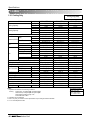
1.2 60Hz
1.2.1 Cooling Only
Model
Cooling Capacity
Heating Capacity
Cooling Only(60Hz)
Unit
W
kcal/h
Btu/h
W
kcal/h
Btu/h
Casing
Body
Dimensions (W*H*D)
Front Panel
Coil
Fan
Rows x Columns x FPI
Face Area
Type
Motor Output
Running Current
Air Flow Rate(H/M/L)
mm
inch
mm
inch
m2
W
A
cmm
cfm
Drive
Speed control
Temperature Control
Sound Absorbing Thermal Insulation Material
Safety Device
Liquid Side
mm(inch)
Pipe Connections Gas Side
mm(inch)
Drain Pipe(OD)
mm
Net Weight
kg(lbs)
Noise Level(Sound Press, 1.5m, H/M/L) dBA±3
Power Supply
Ø / V / Hz
Refrigerant Control
Power cable
mm2
Transmission cable
mm2
Panel Color
Stuffing Quantity Without S/parts
20/40ft
LRNV072TCA(C)0
LRNV092TCA(C)0
LRNV122TCA(C)0
2,100
2,600
3,500
1,806
2,235
3,009
7,165
8,871
11,942
Galvanized Steel Plate Galvanized Steel Plate Galvanized Steel Plate
860*390*180
860*390*180
860*390*180
33.8*15.3*7.0
33.8*15.3*7.0
33.8*15.3*7.0
1050*480*30
1050*480*30
1050*480*30
41.3*18.9*1.2
41.3*18.9*1.2
41.3*18.9*1.2
2*12*18
2*12*21
2*12*21
0.17
0.17
0.17
Cross Flow Fan
Cross Flow Fan
Cross Flow Fan
14
14
14
0.22
0.22
0.22
6/5/4
7/6/5
10/9/8
212/177/141
247/212/177
353/318/283
Direct
Direct
Direct
Phase Control
Phase Control
Phase Control
Microprocessor, Thermostat for cooling Microprocessor, Thermostat for cooling Microprocessor, Thermostat for cooling
Foamed polystrene
Foamed polystrene
Foamed polystrene
Fuse, Thermal Fuse for Fan Motor Fuse, Thermal Fuse for Fan Motor Fuse, Thermal Fuse for Fan Motor
Ø6.35(1/4)
Ø6.35(1/4)
Ø6.35(1/4)
Ø12.7(1/2)
Ø12.7(1/2)
Ø12.7(1/2)
32.0
32.0
32.0
17(37.5)
17(37.5)
17(37.5)
35/32/29
37/34/31
39/36/35
1 / 220 / 60Hz
1 / 220 / 60Hz
1 / 220 / 60Hz
LEV
LEV
LEV
CV2.0 X 3C
CV2.0 X 3C
CV2.0 X 3C
CVV-SB 1.25 X 2C
CVV-SB 1.25 X 2C
CVV-SB 1.25 X 2C
White
White
White
263/539
263/539
263/539
Notes:1. Capacities are based on the following conditions:
Cooling • Indoor temp. 27°C[80.6°F]DB/ 19°C[66.2°F]WB
• Outdoor temp. 35°C[95°F]DB/ 24°C[75.2°F]WB
• Interconnecting Piping Length 7.5m
• Level Difference of Zero
2. Capacities are net capacities
3. Due to our policy of innovation some specifications may be changed without notification
4. L.E.V.:Linear Expansion Valve
Conversion Formula
Kcal/h= kW x 860
Btu/h = kW x 3412
cfm = m3/min x 35.3
Service Manual 25
Specifications
2.2.2 Heat Pump
Heat Pump (60Hz)
Model
Cooling Capacity
Heating Capacity
Unit
W
kcal/h
Btu/h
W
kcal/h
Btu/h
Casing
Body
Dimensions (W*H*D)
Front Panel
Coil
Fan
Rows x Columns x FPI
Face Area
Type
Motor Output
Running Current
Air Flow Rate(H/M/L)
mm
inch
mm
inch
m2
W
A
cmm
cfm
Drive
Speed control
Temperature Control
Sound Absorbing Thermal Insulation Material
Safety Device
Liquid Side
mm(inch)
Pipe Connections Gas Side
mm(inch)
Drain Pipe(OD))
mm
Net Weight
kg(lbs)
Noise Level(Sound Press, 1.5m, H/M/L) dBA±3
Power Supply
Ø / V / Hz
Refrigerant Control
Power cable
mm2
Transmission cable
mm2
Panel Color
Stuffing Quantity Without S/parts
20/40ft
LRNN072TCA(C)0
LRNN092TCA(C)0
LRNN122TCA(C)0
2,100
2,600
3,500
1,806
2,235
3,009
7,165
8,871
11,942
2,363
2,925
3,938
2,031
2,515
3,385
8,061
9,980
13,435
Galvanized Steel Plate Galvanized Steel Plate Galvanized Steel Plate
860*390*180
860*390*180
860*390*180
33.8*15.3*7.0
33.8*15.3*7.0
33.8*15.3*7.0
1050*480*30
1050*480*30
1050*480*30
41.3*18.9*1.2
41.3*18.9*1.2
41.3*18.9*1.2
2*12*18
2*12*21
2*12*21
0.17
0.17
0.17
Cross Flow Fan
Cross Flow Fan
Cross Flow Fan
14
14
14
0.22
0.22
0.22
6/5/4
7/6/5
10/9/8
212/177/141
247/212/177
353/318/283
Direct
Direct
Direct
Phase Control
Phase Control
Phase Control
Microprocessor, Thermostat for cooling and heating Microprocessor, Thermostat for cooling and heating Microprocessor, Thermostat for cooling and heating
Foamed polystrene
Foamed polystrene
Foamed polystrene
Fuse, Thermal Fuse for Fan Motor Fuse, Thermal Fuse for Fan Motor Fuse, Thermal Fuse for Fan Motor
Ø6.35(1/4)
Ø6.35(1/4)
Ø6.35(1/4)
Ø12.7(1/2)
Ø12.7(1/2)
Ø12.7(1/2)
32.0
32.0
32.0
17(37.5)
17(37.5)
17(37.5)
35/32/29
37/34/31
39/36/35
1 / 220 / 60Hz
1 / 220 / 60Hz
1 / 220 / 60Hz
LEV
LEV
LEV
CV2.0 X 3C
CV2.0 X 3C
CV2.0 X 3C
CVV-SB 1.25 X 2C
CVV-SB 1.25 X 2C
CVV-SB 1.25 X 2C
White
White
White
263/539
263/539
263/539
Notes:1. Capacities are based on the following conditions:
Cooling • Indoor temp. 27°C[80.6°F]DB/ 19°C[66.2°F]WB
• Outdoor temp. 35°C[95°F]DB/ 24°C[75.2°F]WB
• Interconnecting Piping Length 7.5m
• Level Difference of Zero
Heating • Indoor temp. 20°C[68°F]DB/ 15°C[59°F]WB
• Outdoor temp. 7°C[44.6°F]DB/ 6°C[42.8°F]WB
• Interconnecting Piping Length 7.5m
• Level Difference of Zero
2. Capacities are net capacities
3. Due to our policy of innovation some specifications may be changed without notification
4. L.E.V.:Linear Expansion Valve
26
Indoor Unit
Conversion Formula
kcal/h = kW x 860
Btu/h = kW x 3412
cfm = m3/min x 35.3
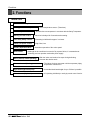
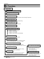
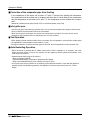
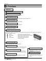
Functions
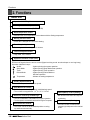
2. Functions
Indoor Unit
Operation ON/OFF by Remote controller
Sensing the Room Temperature
Room temperature control
Starting Current Control
• Room temperature sensor. (Thermistor)
• Maintains the room temperature in accordance with the Setting temperature
• Indoor fan is delayed for 5 seconds at the starting.
Time Delay Safety Control
• Restarting is inhibited for approx. 3 minutes.
Indoor Fan Speed Control
• Jet, High, Med, Low
Soft Dry Operation Mode
• Intermittent operation of fan at low speed.
Airflow Direction Control
• The louver can be set at swing up and down automatically.
Auto Restart
• Although the air-conditioner is turned off by a power failure, it is restarted automatically previous operation mode after power supply.
Deice (defrost) control (Heating)
• Both the indoor and outdoor fan stops during defrosting.
• Hot start after defrost ends.
Hot-start Control (Heating)
• The indoor fan does not rotate until the evaporator piping temperature will be reached at 25°C.
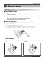
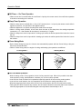
Compact and light design
• To install a unit is very convenient because of smaller
size than textile.
Low noise
• The most advanced low-noise design.
• The adoption of turbo fan and round type heat exchanger give the quietest operation.
Long life filter
• Long life wrinkle(type) and washable and anti-bacteria
filter is adopted.
High head Drain pump
• Built-in drain pump automatically drains water.
• A standard drain-head height of up to 700mm is possible.
High-Ceiling corresponding Function
• According to the height of ceiling, the RPM of indoor fan
motor is selected to increase air reaching distance.
Central Control(Optional)
• It is operating individually or totally by central control function.
Service Manual 27
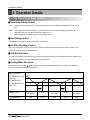
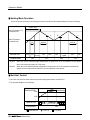
Operation Details
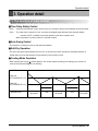
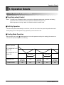
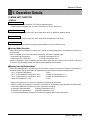
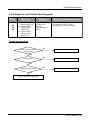
3. Operation Details
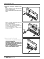
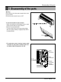
(1) The function of main control
■ Time Delay Safety Control
• 5sec
Vertical louvers are delayed for 5 secs to be opened to prevent the frictional sound between louver and air
flow.
• 30sec
The 4-way valve is ceased for 30sec. to prevent abnormal noise when the Heating operation is OFF or
switched to the other operation mode while compress is off.
While compressor is running, it takes 3~5 seconds to switch.
■ Auto Swing Control
• This function is to swing the louver up and down automatically.
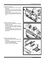
■ Air-Filter Checking Control
• 'Filter' sign will appear on the remote controller display and main body display when an air-filter is polluted. Then
clean the air-filter referring to Owners Manual.
■ Soft-Dry Operation
• The indoor fan speed is automatically set to the low, and fan speed control is not available because of already being
set to the best speed for Dry Operation by microcontroller control.
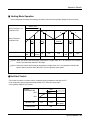
■ Cooling Mode Operation
• When selecting the Cooling( ) Mode Operation, the unit will operate according to the setting by the remote controller and the operation diagram is as follows.
Intake Air Temperature
SET TEMPERATURE +0.5°C
(COMP. ON)
SET TEMPERATURE
SET TEMPERATURE -0.5°C
(COMP. OFF)
INDOOR FAN
COMPRESSOR
28
More than
More than
3 minutes
3 minutes
Selected
fan speed
Low
Selected
fan speed
Low
Selected
fan speed
ON
OFF
ON
OFF
ON
Indoor Unit
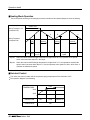
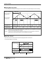
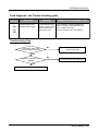
Operation Details
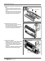
■ Heating Mode Operation
The unit will operate according to the setting by the remote controller and the operation diagram is shown as follows.
Intake Air Temperature.
minimum 3min
Setting Temperature .+3°C
(Compressor OFF)
A
Setting Temperature
(Compressor ON)
INDOOR FAN
1min
(Hot Start)
OFF
COMPRESSOR
Low
Selected
Fan Speed
A
B
minimum
minimum
minimum
10sec.
1min.
10sec.
Low
Selecting fan Low
speed
Low
ON
OFF
OFF
ON
OFF
OFF
A point; While the indoor Heat-Exchanger temperature is higher than 40°C fan operates at low speed,
when it becomes lower than 40˚C fan stops.
B point; When the indoor Heat-Exchanger temperature is higher than 42°C, fan operates at selected fan
speed, when it becomes lower than 39°C, the fan operates at low speed.
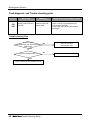
■ Hot-Start Control
• The indoor fan sdoes not rotate until the evaporator piping temperature reaches to 25°C.
• If the evaporator piping temperature drops below 22°C, indoor fan stops again.
• The operation diagram is as follows.
PIPING
TEMPERATURE
25°C
1min
22°C
INDOOR FAN
COMPRESSOR
OFF
LOW
Selected
fan speed
ON
Service Manual 29
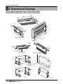
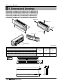
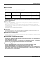
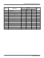
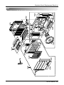
Dimensional Drawings
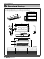
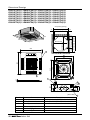
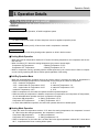
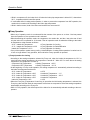
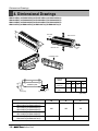
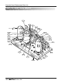
4. Dimensional Drawings
LRNV076TCA(C)0/LRNN076TCA(C)0/LRNV072TCA(C)0/LRNN072TCA(C)0
LRNV096TCA(C)0/LRNN096TCA(C)0/LRNV092TCA(C)0/LRNN092TCA(C)0
LRNV126TCA(C)0/LRNN126TCA(C)0/LRNV122TCA(C)0/LRNN122TCA(C)0
1,000 (Ceiling opening)
4
16.7
7
1
30.8
931.6
893.4
860
846
328.4 (Hanging bolt) 30.8
430 (Ceiling opening)
390
931.6
893.4 (Hanging bolt)
860
2
3
155
164
194.4
390
328.4
50
42.7
37
91.6
97.7
116.3
Ø80
180
430
141.8
91.6
130
Ø55
180
180
1050
694.5
5
480
6
(unit : mm)
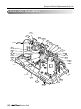
Number
1
2
3
4
5
6
30
Indoor Unit
Name
Liquid pipe connection
Gas pipe connection
Drain pipe connection
Power supply connection
Air discharge grill
Air suction grill
Descripition
ø6.35 flare
ø12.7 flare
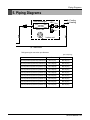
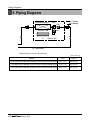
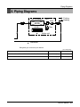
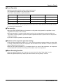
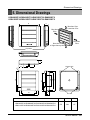
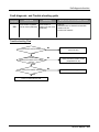
Piping Diarams
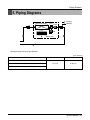
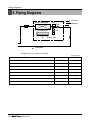
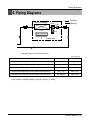
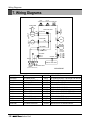
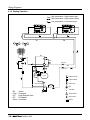
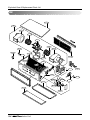
5. Piping Diagrams
Heat Exchanger
LEV
Filter
:Cooling
:Heating
C.F.F.
Filter
lndoor unit
: Thermistor
Refrigerant pipe connection port diameter
[unit: mm(inch)]
Model
Gas
Liquid
12.7(1/2)
6.35(1/4)
LRNV076TCA(C)0/LRNN076TCA(C)0/LRNV072TCA(C)0/LRNN072TCA(C)0
LRNV096TCA(C)0/LRNN096TCA(C)0/LRNV092TCA(C)0/LRNN092TCA(C)0
LRNV126TCA(C)0/LRNN126TCA(C)0/LRNV122TCA(C)0/LRNN122TCA(C)0
Service Manual 31
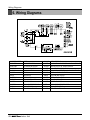
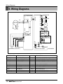
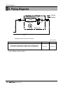
Wiring Diagrams
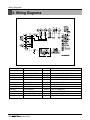
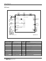
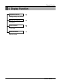
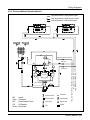
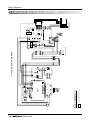
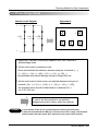
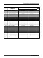
6. Wiring Diagrams
CONNECTOR NUMBER
CN-POWER
CN-MOTOR2
CN-D/PUMP
SPEC
AC POWER SUPPLY
AC FAN MOTOR OUTPUT
DRAIN PUMP OUTPUT
CN-COMM
CN-DISP1
COMMUNICATION
DISPLAY
CN-LEV
CN-STEP/M1
CN-FLOAT
CN-PIPE
CN-PIPE/O
CN-ROOM
CN-REMO
LEV OUTPUT
STEP MOTOR
FLOAT SWITCH INPUT
PIPE SENSOR
DISCHARGE PIPE SENSOR
ROOM SENSOR
REMOTE CONTROLLER
32
Indoor Unit
COLOR
WHITE
YELLOW
WHITE
WHITE
BLUE
WHITE
WHITE
BLUE
WHITE
RED
YELLOW
WHITE
DESCRIPTION
AC POWER LINE INPUT FOR INDOOR CONTROLLER
MOTOR OUTPUT OF PHASE CONTROL
AC OUTPUT FOR DRAIN PUMP
CONNECTION BETWEEN INDOOR AND OUTDOOR
DISPLAY OF INDOOR STATUS
LEV CONTROL OUTPUT
STEP MOTOR OUTPUT
FLOAT SWITCH SENSING
PIPE THERMISTOR
DISCHARGE PIPE THERMISTOR
ROOM THERMISTOR
REMOTE CONTROL LINE
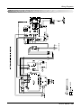
Ceiling Mounted Cassette Type (4Way)
1. Specifications .............................................................................34
2. Functions ....................................................................................46
3. Operation Details........................................................................47
4. Dimensional Drawings ...............................................................49
5. Piping Diagrams .........................................................................51
6. Wiring Diagrams .........................................................................52
Service Manual 33
Specifications
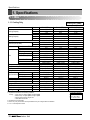
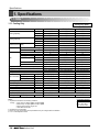
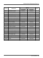
1. Specifications
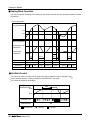
1.1 50Hz
1.1.1 Cooling Only
Model
Cooling Capacity
Heating Capacity
Cooling Only (50Hz)
Unit
W
kcal/h
Btu/h
W
kcal/h
Btu/h
Casing
Body
Dimensions (W*H*D)
Front Panel
Coil
Fan
Rows x Columns x FPI
Face Area
Type
Motor Output
Running Current
Air Flow Rate(H/M/L)
mm
inch
mm
inch
m2
W
A
cmm
cfm
Drive
Speed control
Temperature Control
Sound Absorbing Thermal Insulation Material
Safety Device
Liquid Side
mm(inch)
Pipe Connections Gas Side
mm(inch)
Drain Pipe(OD)
mm
Net Weight
kg(lbs)
Noise Level(Sound Press, 1.5m, H/M/L) dBA±3
Power Supply
Ø / V / Hz
Refrigerant Control
Power cable
mm2
Transmission cable
mm2
Panel Color
Stuffing Quantity Without S/parts
20/40ft
LRNV126TEA(C)0
LRNV186TEA(C)0
LRNV216TDA(C)0
3,500
5,300
6,200
3,009
4,557
5,331
11,942
18,084
21,155
Galvanized Steel Plate Galvanized Steel Plate Galvanized Steel Plate
570*570*269
570*570*269
840*840*290
22.4*22.4*10.5
22.4*22.4*10.5
33.0*33.0*11.4
670*670*30
670*670*30
950*950*30
26.4*26.4*1.2
26.4*26.4*1.2
37.4*37.4*1.2
2*11*19
2*11*19
2*12*21
0.27
0.27
2*0.26
Turbo Fan
Turbo Fan
Turbo Fan
20
25
60
0.69
0.69
0.80
11/10/9
13/12/10
18/15.9/13.9
389/353/318
459/424/353
636/562/491
Direct
Direct
Direct
Phase Control
Phase Control
Phase Control
Microprocessor, Thermostat for cooling Microprocessor, Thermostat for cooling Microprocessor, Thermostat for cooling
Foamed polystrene
Foamed polystrene
Foamed polystrene
Fuse, Thermal Fuse for Fan Motor Fuse, Thermal Fuse for Fan Motor Fuse, Thermal Fuse for Fan Motor
Ø6.35(1/4)
Ø9.52(3/8)
Ø9.52(3/8)
Ø12.7(1/2)
Ø15.88(5/8)
Ø15.88(5/8)
32.0
32.0
32.0
19(41.9)
19(41.9)
32(70.5)
38/35/32
41/39/37
40/37/35
1 / 220 ~ 240 / 50
1 / 220 ~ 240 / 50
1 / 220 ~ 240 / 50
LEV
LEV
LEV
CV2.0 X 3C
CV2.0 X 3C
CV2.0 X 3C
CVV-SB 1.25 X 2C
CVV-SB 1.25 X 2C
CVV-SB 1.25 X 2C
White
White
White
189/378
189/378
72/144
Notes:1. Capacities are based on the following conditions:
Cooling • Indoor temp. 27°C[80.6°F]DB/ 19°C[66.2°F]WB
• Outdoor temp. 35°C[95°F]DB/ 24°C[75.2°F]WB
• Interconnecting Piping Length 7.5m
• Level Difference of Zero
2. Capacities are net capacities
3. Due to our policy of innovation some specifications may be changed without notification
34
Indoor Unit
Conversion Formula
Kcal/h= kW x 860
Btu/h = kW x 3412
cfm = m3/min x 35.3
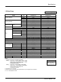
Specifications
Cooling Only (50Hz)
Model
Cooling Capacity
Heating Capacity
Unit
W
kcal/h
Btu/h
W
kcal/h
Btu/h
Casing
Body
Dimensions (W*H*D)
Front Panel
Coil
Fan
Rows x Columns x FPI
Face Area
Type
Motor Output
Running Current
Air Flow Rate(H/M/L)
mm
inch
mm
inch
m2
W
A
cmm
cfm
Drive
Speed control
Temperature Control
Sound Absorbing Thermal Insulation Material
Safety Device
Liquid Side
mm(inch)
Pipe Connections Gas Side
mm(inch)
Drain Pipe(OD)
mm
Net Weight
kg(lbs)
Noise Level(Sound Press, 1.5m, H/M/L) dBA±3
Power Supply
Ø / V / Hz
Refrigerant Control
Power cable
mm2
Transmission cable
mm2
Panel Color
Stuffing Quantity Without S/parts
20/40ft
LRNV246TDA(C)0
LRNV286TDA(C)0
LRNV366TDA(C)0
7,000
8,200
10,600
6,019
7,052
9,116
23,885
27,995
36,168
Galvanized Steel Plate Galvanized Steel Plate Galvanized Steel Plate
840*840*290
840*840*290
840*840*290
33.0*33.0*11.4
33.0*33.0*11.4
33.0*33.0*11.4
950*950*30
950*950*30
950*950*30
37.4*37.4*1.2
37.4*37.4*1.2
37.4*37.4*1.2
2*12*21
2*12*21
2*12*21
2*0.26
2*0.26
2*0.26
Turbo Fan
Turbo Fan
Turbo Fan
60
60
60
0.80
0.80
1.10
19/17/15
23/21/18
26/24/22
671/601/530
813/742/636
919/848/777
Direct
Direct
Direct
Phase Control
Phase Control
Phase Control
Microprocessor, Thermostat for cooling Microprocessor, Thermostat for cooling Microprocessor, Thermostat for cooling
Foamed polystrene
Foamed polystrene
Foamed polystrene
Fuse, Thermal Fuse for Fan Motor Fuse, Thermal Fuse for Fan Motor Fuse, Thermal Fuse for Fan Motor
Ø9.52(3/8)
Ø9.52(3/8)
Ø9.52(3/8)
Ø15.88(5/8)
Ø15.88(5/8)
Ø19.05(3/4)
32.0
32.0
32.0
32(70.5)
32(70.5)
32(70.5)
41/38/36
42/40/38
43/41/39
1 / 220 ~ 240 / 50
1 / 220 ~ 240 / 50
1 / 220 ~ 240 / 50
LEV
LEV
LEV
CV2.0 X 3C
CV2.0 X 3C
CV2.0 X 3C
CVV-SB 1.25 X 2C
CVV-SB 1.25 X 2C
CVV-SB 1.25 X 2C
White
White
White
72/144
72/144
72/144
Notes:1. Capacities are based on the following conditions:
Cooling • Indoor temp. 27°C[80.6°F]DB/ 19°C[66.2°F]WB
• Outdoor temp. 35°C[95°F]DB/ 24°C[75.2°F]WB
• Interconnecting Piping Length 7.5m
• Level Difference of Zero
2. Capacities are net capacities
3. Due to our policy of innovation some specifications may be changed without notification
4. L.E.V.: Linear Expansion Valve
35
35
Indoor
IndoorUnit
Unit
Conversion Formula
Kcal/h= kW x 860
Btu/h = kW x 3412
cfm = m3/min x 35.3
Service Manual 35
Specifications
Cooling Only (50Hz)
Model
Cooling Capacity
Heating Capacity
Unit
W
kcal/h
Btu/h
W
kcal/h
Btu/h
Casing
Body
Dimensions (W*H*D)
Front Panel
Coil
Fan
Rows x Columns x FPI
Face Area
Type
Motor Output
Running Current
Air Flow Rate(H/M/L)
mm
inch
mm
inch
m2
W
A
cmm
cfm
Drive
Speed control
Temperature Control
Sound Absorbing Thermal Insulation Material
Safety Device
Liquid Side
mm(inch)
Pipe Connections Gas Side
mm(inch)
Drain Pipe(OD)
mm
Net Weight
kg(lbs)
Noise Level(Sound Press, 1.5m, H/M/L) dBA±3
Power Supply
Ø / V / Hz
Refrigerant Control
Power cable
mm2
Transmission cable
mm2
Panel Color
Stuffing Quantity Without S/parts
20/40ft
LRNV386TDA(C)0
LRNV426TDA(C)0
LRNV486TDA(C)0
11,100
12,300
14,100
9,544
10,578
12,126
37,875
41,992
48,137
Galvanized Steel Plate Galvanized Steel Plate Galvanized Steel Plate
840*840*290
840*840*290
840*840*290
33.0*33.0*11.4
33.0*33.0*11.4
33.0*33.0*11.4
950*950*30
950*950*30
950*950*30
37.4*37.4*1.2
37.4*37.4*1.2
37.4*37.4*1.2
2*12*21
2*12*21
2*12*21
2*0.26
2*0.26
2*0.26
Turbo Fan
Turbo Fan
Turbo Fan
60
60
60
1.10
1.10
1.10
28/26 /24
32.5/30/28.1
34.5/32.5/30
989/919/848
1148/1060/993
1219/1148/1060
Direct
Direct
Direct
Phase Control
Phase Control
Phase Control
Microprocessor, Thermostat for cooling Microprocessor, Thermostat for cooling Microprocessor, Thermostat for cooling
Foamed polystrene
Foamed polystrene
Foamed polystrene
Fuse, Thermal Fuse for Fan Motor Fuse, Thermal Fuse for Fan Motor Fuse, Thermal Fuse for Fan Motor
Ø9.52(3/8)
Ø9.52(3/8)
Ø9.52(3/8)
Ø19.05(3/4)
Ø19.05(3/4)
Ø19.05(3/4)
32.0
32.0
32.0
32(70.5)
32(70.5)
32(70.5)
43.5/41.5/39.5
44/42/40
45/43/41
1 / 220 ~ 240 / 50
1, 220 ~ 240, 50
1 / 220 ~ 240 / 50
LEV
LEV
LEV
CV2.0 X 3C
CV2.0 X 3C
CV2.0 X 3C
CVV-SB 1.25 X 2C
CVV-SB 1.25 X 2C
CVV-SB 1.25 X 2C
White
White
White
72/144
72/144
72/144
Notes:1. Capacities are based on the following conditions:
Cooling • Indoor temp. 27°C[80.6°F]DB/ 19°C[66.2°F]WB
• Outdoor temp. 35°C[95°F]DB/ 24°C[75.2°F]WB
• Interconnecting Piping Length 7.5m
• Level Difference of Zero
2. Capacities are net capacities
3. Due to our policy of innovation some specifications may be changed without notification
4. L.E.V.: Linear Expansion Valve
36
Indoor Unit
Conversion Formula
Kcal/h= kW x 860
Btu/h = kW x 3412
cfm = m3/min x 35.3
Specifications
2.1.2 Heat Pump
Model
Cooling Capacity
Heating Capacity
Heat Pump (50Hz)
Unit
W
kcal/h
Btu/h
W
kcal/h
Btu/h
Casing
Body
Dimensions (W*H*D)
Front Panel
Coil
Fan
Rows x Columns x FPI
Face Area
Type
Motor Output
Running Current
Air Flow Rate(H/M/L)
mm
inch
mm
inch
m2
W
A
cmm
cfm
Drive
Speed control
Temperature Control
Sound Absorbing Thermal Insulation Material
Safety Device
Liquid Side
mm(inch)
Pipe Connections Gas Side
mm(inch)
Drain Pipe(OD)
mm
Net Weight
kg(lbs)
Noise Level(Sound Press, 1.5m, H/M/L) dBA±3
Power Supply
Ø / V / Hz
Refrigerant Control
Power cable
mm2
Transmission cable
mm2
Panel Color
Stuffing Quantity Without S/parts
20/40ft
LRNN126TEA(C)0
LRNN186TEA(C)0
LRNN216TDA(C)0
3,500
5,300
6,200
3,009
4,557
5,331
11,942
18,084
21,155
3,938
5,963
6,975
3,385
5,127
5,997
13,435
20,345
23,800
Galvanized Steel Plate Galvanized Steel Plate Galvanized Steel Plate
570*570*269
570*570*269
840*840*290
22.4*22.4*10.5
22.4*22.4*10.5
33.0*33.0*11.4
670*670*30
670*670*30
950*950*30
26.4*26.4*1.2
26.4*26.4*1.2
37.4*37.4*1.2
2*11*19
2*11*19
2*12*21
0.27
0.27
2*0.26
Turbo Fan
Turbo Fan
Turbo Fan
20
25
60
0.69
0.69
0.80
11/10/9
13/12/10
18/15.9/13.9
389/353/318
459/424/353
636/562/491
Direct
Direct
Direct
Phase Control
Phase Control
Phase Control
Microprocessor, Thermostat for cooling and heating Microprocessor, Thermostat for cooling and heating Microprocessor, Thermostat for cooling and heating
Foamed polystrene
Foamed polystrene
Foamed polystrene
Fuse, Thermal Fuse for Fan Motor Fuse, Thermal Fuse for Fan Motor
Fuse, Thermal Fuse for Fan Motor
Ø6.35(1/4)
Ø9.52(3/8)
Ø9.52(3/8)
Ø12.7(1/2)
Ø15.88(5/8)
Ø15.88(5/8)
32.0
32.0
32.0
19(41.9)
19(41.9)
32(70.5)
38/35/32
41/39/37
40/37/35
1 / 220 ~ 240 / 50
1 / 220 ~ 240 / 50
1 / 220 ~ 240 / 50
LEV
LEV
LEV
CV2.0 X 3C
CV2.0 X 3C
CV2.0 X 3C
CVV-SB 1.25 X 2C
CVV-SB 1.25 X 2C
CVV-SB 1.25 X 2C
White
White
White
189/378
189/378
72/144
Notes:1. Capacities are based on the following conditions:
Cooling • Indoor temp. 27°C[80.6°F]DB/ 19°C[66.2°F]WB
• Outdoor temp. 35°C[95°F]DB/ 24°C[75.2°F]WB
• Interconnecting Piping Length 7.5m
• Level Difference of Zero
Heating • Indoor temp. 20°C[68°F]DB/ 15°C[59°F]WB
• Outdoor temp. 7°C[44.6°F]DB/ 6°C[42.8°F]WB
• Interconnecting Piping Length 7.5m
• Level Difference of Zero
2. Capacities are net capacities
3. Due to our policy of innovation some specifications may be changed without notification
4. L.E.V.:Linear Expansion Valve
Conversion Formula
Kcal/h= kW x 860
Btu/h = kW x 3412
cfm = m3/min x 35.3
Service Manual 37
Specifications
Heat Pump (50Hz)
Model
Cooling Capacity
Heating Capacity
Unit
W
kcal/h
Btu/h
W
kcal/h
Btu/h
Casing
Body
Dimensions (W*H*D)
Front Panel
Coil
Fan
Rows x Columns x FPI
Face Area
Type
Motor Output
Running Current
Air Flow Rate(H/M/L)
mm
inch
mm
inch
m2
W
A
cmm
cfm
Drive
Speed control
Temperature Control
Sound Absorbing Thermal Insulation Material
Safety Device
Liquid Side
mm(inch)
Pipe Connections Gas Side
mm(inch)
Drain Pipe(OD)
mm
Net Weight
kg(lbs)
Noise Level(Sound Press, 1.5m, H/M/L) dBA±3
Power Supply
Ø / V / Hz
Refrigerant Control
Power cable
mm2
Transmission cable
mm2
Panel Color
Stuffing Quantity Without S/parts
20/40ft
LRNN246TDA(C)0
LRNN286TDA(C)0
LRNN366TDA(C)0
7,000
8,200
10,600
6,019
7,052
9,116
23,885
27,995
36,168
7,875
9,225
11,925
6,771
7,934
10,253
26,870
31,494
40,689
Galvanized Steel Plate Galvanized Steel Plate Galvanized Steel Plate
840*840*290
840*840*290
840*840*290
33.0*33.0*11.4
33.0*33.0*11.4
33.0*33.0*11.4
950*950*30
950*950*30
950*950*30
37.4*37.4*1.2
37.4*37.4*1.2
37.4*37.4*1.2
2*12*21
2*12*21
2*12*21
2*0.26
2*0.26
2*0.26
Turbo Fan
Turbo Fan
Turbo Fan
60
60
60
0.80
0.80
1.10
19/17/15
23/21/18
26/24/22
671/601/530
813/742/636
919/848/777
Direct
Direct
Direct
Phase Control
Phase Control
Phase Control
Microprocessor, Thermostat for cooling and heating Microprocessor, Thermostat for cooling and heating Microprocessor, Thermostat for cooling and heating
Foamed polystrene
Foamed polystrene
Foamed polystrene
Fuse, Thermal Fuse for Fan Motor Fuse, Thermal Fuse for Fan Motor
Fuse, Thermal Fuse for Fan Motor
Ø9.52(3/8)
Ø9.52(3/8)
Ø9.52(3/8)
Ø15.88(5/8)
Ø15.88(5/8)
Ø19.05(3/4)
32.0
32.0
32.0
32(70.5)
32(70.5)
32(70.5)
41/38/36
42/40/38
43/41/39
1 / 220 ~ 240 / 50
1 / 220 ~ 240 / 50
1 / 220 ~ 240 / 50
LEV
LEV
LEV
CV2.0 X 3C
CV2.0 X 3C
CV2.0 X 3C
CVV-SB 1.25 X 2C
CVV-SB 1.25 X 2C
CVV-SB 1.25 X 2C
White
White
White
72/144
72/144
72/144
Notes:1. Capacities are based on the following conditions:
Cooling • Indoor temp. 27°C[80.6°F]DB/ 19°C[66.2°F]WB
• Outdoor temp. 35°C[95°F]DB/ 24°C[75.2°F]WB
• Interconnecting Piping Length 7.5m
• Level Difference of Zero
Heating • Indoor temp. 20°C[68°F]DB/ 15°C[59°F]WB
• Outdoor temp. 7°C[44.6°F]DB/ 6°C[42.8°F]WB
• Interconnecting Piping Length 7.5m
• Level Difference of Zero
2. Capacities are net capacities
3. Due to our policy of innovation some specifications may be changed without notification
4. L.E.V.:Linear Expansion Valve
38
Indoor Unit
Conversion Formula
Kcal/h= kW x 860
Btu/h = kW x 3412
cfm = m3/min x 35.3
Specifications
Heat Pump (50Hz)
Model
Cooling Capacity
Heating Capacity
Unit
W
kcal/h
Btu/h
W
kcal/h
Btu/h
Casing
Body
Dimensions (W*H*D)
Front Panel
Coil
Fan
Rows x Columns x FPI
Face Area
Type
Motor Output
Running Current
Air Flow Rate(H/M/L)
mm
inch
mm
inch
m2
W
A
cmm
cfm
Drive
Speed control
Temperature Control
Sound Absorbing Thermal Insulation Material
Safety Device
Liquid Side
mm(inch)
Pipe Connections Gas Side
mm(inch)
Drain Pipe(OD)
mm
Net Weight
kg(lbs)
Noise Level(Sound Press, 1.5m, H/M/L) dBA±3
Power Supply
Ø / V / Hz
Refrigerant Control
Power cable
mm2
Transmission cable
mm2
Panel Color
Stuffing Quantity Without S/parts
20/40ft
LRNN386TDA(C)0
LRNN426TDA(C)0
LRNN486TDA(C)0
11,100
12,300
14,100
9,544
10,578
12,126
37,875
41,992
48,137
12,487
13,838
15,863
10,737
11,040
13,156
42,607
43,829
54,156
Galvanized Steel Plate Galvanized Steel Plate Galvanized Steel Plate
840*840*290
840*840*290
840*840*290
33.0*33.0*11.4
33.0*33.0*11.4
33.0*33.0*11.4
950*950*30
950*950*30
950*950*30
37.4*37.4*1.2
37.4*37.4*1.2
37.4*37.4*1.2
2*12*21
2*12*21
2*12*21
2*0.26
2*0.26
2*0.26
Turbo Fan
Turbo Fan
Turbo Fan
60
60
60
1.10
1.10
1.10
28/26 /24
32.5/30/28.1
34.5/32.5/30
989/919/848
1148/1060/993
1219/1148/1060
Direct
Direct
Direct
Phase Control
Phase Control
Phase Control
Microprocessor, Thermostat for cooling and heating Microprocessor, Thermostat for cooling and heating Microprocessor, Thermostat for cooling and heating
Foamed polystrene
Foamed polystrene
Foamed polystrene
Fuse, Thermal Fuse for Fan Motor Fuse, Thermal Fuse for Fan Motor
Fuse, Thermal Fuse for Fan Motor
Ø9.52(3/8)
Ø9.52(3/8)
Ø9.52(3/8)
Ø19.05(3/4)
Ø19.05(3/4)
Ø19.05(3/4)
32.0
32.0
32.0
32(70.5)
32(70.5)
32(70.5)
43.5/41.5/39.5
44/42/40
45/43/41
1 / 220 ~ 240 / 50
1 / 220 ~ 240 / 50
1 / 220 ~ 240 / 50
LEV
LEV
LEV
CV2.0 X 3C
CV2.0 X 3C
CV2.0 X 3C
CVV-SB 1.25 X 2C
CVV-SB 1.25 X 2C
CVV-SB 1.25 X 2C
White
White
White
72/144
72/144
72/144
Notes:1. Capacities are based on the following conditions:
Cooling • Indoor temp. 27°C[80.6°F]DB/ 19°C[66.2°F]WB
• Outdoor temp. 35°C[95°F]DB/ 24°C[75.2°F]WB
• Interconnecting Piping Length 7.5m
• Level Difference of Zero
Heating • Indoor temp. 20°C[68°F]DB/ 15°C[59°F]WB
• Outdoor temp. 7°C[44.6°F]DB/ 6°C[42.8°F]WB
• Interconnecting Piping Length 7.5m
• Level Difference of Zero
2. Capacities are net capacities
3. Due to our policy of innovation some specifications may be changed without notification
4. L.E.V.:Linear Expansion Valve
Conversion Formula
Kcal/h= kW x 860
Btu/h = kW x 3412
cfm = m3/min x 35.3
Service Manual 39
Specifications
1.2 60Hz
1.2.1 Cooling Only
Model
Cooling Capacity
Heating Capacity
Cooling Only (60Hz)
Unit
W
kcal/h
Btu/h
W
kcal/h
Btu/h
Casing
Body
Dimensions (W*H*D)
Front Panel
Coil
Fan
Rows x Columns x FPI
Face Area
Type
Motor Output
Running Current
Air Flow Rate(H/M/L)
mm
inch
mm
inch
m2
W
A
cmm
cfm
Drive
Speed control
Temperature Control
Sound Absorbing Thermal Insulation Material
Safety Device
Liquid Side
mm(inch)
Pipe Connections Gas Side
mm(inch)
Drain Pipe(OD)
mm
Net Weight
kg(lbs)
Noise Level(Sound Press, 1.5m, H/M/L) dBA±3
Power Supply
Ø / V / Hz
Refrigerant Control
Power cable
mm2
Transmission cable
mm2
Panel Color
Stuffing Quantity Without S/parts
20/40ft
LRNV122TEA(C)0
3,500
3,009
11,942
Galvanized Steel Plate
570*570*269
22.4*22.4*10.5
670*670*30
26.4*26.4*1.2
2*11*19
0.27
Turbo Fan
20
0.69
11/10/9
389/353/318
Direct
Phase Control
Microprocessor, Thermostat for cooling
Foamed polystrene
Fuse, Thermal Fuse for Fan Motor
Ø6.35(1/4)
Ø12.7(1/2)
32.0
19(41.9)
38/35/32
1 / 220 / 60
LEV
CV2.0 X 3C
CVV-SB 1.25 X 2C
White
189/378
LRNV182TEA(C)0
5,300
4,557
18,084
Galvanized Steel Plate
570*570*269
22.4*22.4*10.5
670*670*30
26.4*26.4*1.2
2*11*19
0.27
Turbo Fan
25
0.69
13/12/10
459/424/353
Direct
Phase Control
Microprocessor, Thermostat for cooling
Foamed polystrene
Fuse, Thermal Fuse for Fan Motor
Ø9.52(3/8)
Ø15.88(5/8)
32.0
19(41.9)
41/39/37
1 / 220 / 60
LEV
CV2.0 X 3C
CVV-SB 1.25 X 2C
White
189/378
Notes:1. Capacities are based on the following conditions:
Cooling • Indoor temp. 27°C[80.6°F]DB/ 19°C[66.2°F]WB
• Outdoor temp. 35°C[95°F]DB/ 24°C[75.2°F]WB
• Interconnecting Piping Length 7.5m
• Level Difference of Zero
2. Capacities are net capacities
3. Due to our policy of innovation some specifications may be changed without notification
4. L.E.V.:Linear Expansion Valve
40
Indoor Unit
LRNV212TDA(C)0
6,200
5,331
21,155
Galvanized Steel Plate
840*840*290
33.0*33.0*11.4
950*950*30
37.4*37.4*1.2
2*12*21
2*0.26
Turbo Fan
60
0.80
18/15.9/13.9
636/562/491
Direct
Phase Control
Microprocessor, Thermostat for cooling
Foamed polystrene
Fuse, Thermal Fuse for Fan Motor
Ø9.52(3/8)
Ø15.88(5/8)
32.0
32(70.5)
40/37/35
1 / 220 / 60
LEV
CV2.0 X 3C
CVV-SB 1.25 X 2C
White
72/144
Conversion Formula
Kcal/h= kW x 860
Btu/h = kW x 3412
cfm = m3/min x 35.3
Specifications
Cooling Only (60Hz)
Model
Cooling Capacity
Heating Capacity
Unit
W
kcal/h
Btu/h
W
kcal/h
Btu/h
Casing
Body
Dimensions (W*H*D)
Front Panel
Coil
Fan
Rows x Columns x FPI
Face Area
Type
Motor Output
Running Current
Air Flow Rate(H/M/L)
mm
inch
mm
inch
m2
W
A
cmm
cfm
Drive
Speed control
Temperature Control
Sound Absorbing Thermal Insulation Material
Safety Device
Liquid Side
mm(inch)
Pipe Connections Gas Side
mm(inch)
Drain Pipe(OD)
mm
Net Weight
kg(lbs)
Noise Level(Sound Press, 1.5m, H/M/L) dBA±3
Power Supply
Ø / V / Hz
Refrigerant Control
Power cable
mm2
Transmission cable
mm2
Panel Color
Stuffing Quantity Without S/parts
20/40ft
LRNV242TDA(C)0
LRNV282TDA(C)0
LRNV362TDA(C)0
7,000
8,200
10,600
6,019
7,052
9,116
23,885
27,995
36,168
Galvanized Steel Plate Galvanized Steel Plate Galvanized Steel Plate
840*840*290
840*840*290
840*840*290
33.0*33.0*11.4
33.0*33.0*11.4
33.0*33.0*11.4
950*950*30
950*950*30
950*950*30
37.4*37.4*1.2
37.4*37.4*1.2
37.4*37.4*1.2
2*12*21
2*12*21
2*12*21
2*0.26
2*0.26
2*0.26
Turbo Fan
Turbo Fan
Turbo Fan
60
60
60
0.80
0.80
1.10
19/17/15
23/21/18
26/24/22
671/601/530
813/742/636
919/848/777
Direct
Direct
Direct
Phase Control
Phase Control
Phase Control
Microprocessor, Thermostat for cooling Microprocessor, Thermostat for cooling Microprocessor, Thermostat for cooling
Foamed polystrene
Foamed polystrene
Foamed polystrene
Fuse, Thermal Fuse for Fan Motor Fuse, Thermal Fuse for Fan Motor Fuse, Thermal Fuse for Fan Motor
Ø9.52(3/8)
Ø9.52(3/8)
Ø9.52(3/8)
Ø15.88(5/8)
Ø15.88(5/8)
Ø19.05(3/4)
32.0
32.0
32.0
32(70.5)
32(70.5)
32(70.5)
41/38/36
42/40/38
43/41/39
1 / 220 / 60
1 / 220 / 60
1 / 220 / 60
LEV
LEV
LEV
CV2.0 X 3C
CV2.0 X 3C
CV2.0 X 3C
CVV-SB 1.25 X 2C
CVV-SB 1.25 X 2C
CVV-SB 1.25 X 2C
White
White
White
72/144
72/144
72/144
Notes:1. Capacities are based on the following conditions:
Cooling • Indoor temp. 27°C[80.6°F]DB/ 19°C[66.2°F]WB
• Outdoor temp. 35°C[95°F]DB/ 24°C[75.2°F]WB
• Interconnecting Piping Length 7.5m
• Level Difference of Zero
2. Capacities are net capacities
3. Due to our policy of innovation some specifications may be changed without notification
4. L.E.V.:Linear Expansion Valve
Conversion Formula
Kcal/h= kW x 860
Btu/h = kW x 3412
cfm = m3/min x 35.3
Service Manual 41
Specifications
Cooling Only (60Hz)
Model
Cooling Capacity
Heating Capacity
Unit
W
kcal/h
Btu/h
W
kcal/h
Btu/h
Casing
Body
Dimensions (W*H*D)
Front Panel
Coil
Fan
Rows x Columns x FPI
Face Area
Type
Motor Output
Running Current
Air Flow Rate(H/M/L)
mm
inch
mm
inch
m2
W
A
cmm
cfm
Drive
Speed control
Temperature Control
Sound Absorbing Thermal Insulation Material
Safety Device
Liquid Side
mm(inch)
Pipe Connections Gas Side
mm(inch)
Drain Pipe(OD)
mm
Net Weight
kg(lbs)
Noise Level(Sound Press, 1.5m, H/M/L) dBA±3
Power Supply
Ø / V / Hz
Refrigerant Control
Power cable
mm2
Transmission cable
mm2
Panel Color
Stuffing Quantity Without S/parts
20/40ft
LRNV382TDA(C)0
11,100
9,544
37,875
Galvanized Steel Plate
840*840*290
33.0*33.0*11.4
950*950*30
37.4*37.4*1.2
2*12*21
2*0.26
Turbo Fan
60
1.10
28/26 /24
989/919/848
Direct
Phase Control
Microprocessor, Thermostat for cooling
Foamed polystrene
Fuse, Thermal Fuse for Fan Motor
Ø9.52(3/8)
Ø19.05(3/4)
32.0
32(70.5)
43.5/41.5/39.5
1 / 220 / 60
LEV
CV2.0 X 3C
CVV-SB 1.25 X 2C
White
72/144
LRNV422TDA(C)0
12,300
10,578
41,992
Galvanized Steel Plate
840*840*290
33.0*33.0*11.4
950*950*30
37.4*37.4*1.2
2*12*21
2*0.26
Turbo Fan
60
1.10
32.5/30/28.1
1148/1060/993
Direct
Phase Control
Microprocessor, Thermostat for cooling
Foamed polystrene
Fuse, Thermal Fuse for Fan Motor
Ø9.52(3/8)
Ø19.05(3/4)
32.0
32(70.5)
44/42/40
1 / 220 / 60
LEV
CV2.0 X 3C
CVV-SB 1.25 X 2C
White
72/144
Notes:1. Capacities are based on the following conditions:
Cooling • Indoor temp. 27°C[80.6°F]DB/ 19°C[66.2°F]WB
• Outdoor temp. 35°C[95°F]DB/ 24°C[75.2°F]WB
• Interconnecting Piping Length 7.5m
• Level Difference of Zero
2. Capacities are net capacities
3. Due to our policy of innovation some specifications may be changed without notification
4. L.E.V.:Linear Expansion Valve
42
Indoor Unit
LRNV482TDA(C)0
14,100
12,126
48,137
Galvanized Steel Plate
840*840*290
33.0*33.0*11.4
950*950*30
37.4*37.4*1.2
2*12*21
2*0.26
Turbo Fan
60
1.10
34.5/32.5/30
1219/1148/1060
Direct
Phase Control
Microprocessor, Thermostat for cooling
Foamed polystrene
Fuse, Thermal Fuse for Fan Motor
Ø9.52(3/8)
Ø19.05(3/4)
32.0
32(70.5)
45/43/41
1 / 220 / 60
LEV
CV2.0 X 3C
CVV-SB 1.25 X 2C
White
72/144
Conversion Formula
Kcal/h= kW x 860
Btu/h = kW x 3412
cfm = m3/min x 35.3
Specifications
2.2.2 Heat Pump
Model
Cooling Capacity
Heating Capacity
Heat Pump (60Hz)
Unit
W
kcal/h
Btu/h
W
kcal/h
Btu/h
Casing
Body
Dimensions (W*H*D)
Front Panel
Coil
Fan
Rows x Columns x FPI
Face Area
Type
Motor Output
Running Current
Air Flow Rate(H/M/L)
mm
inch
mm
inch
m2
W
A
cmm
cfm
Drive
Speed control
Temperature Control
Sound Absorbing Thermal Insulation Material
Safety Device
Liquid Side
mm(inch)
Pipe Connections Gas Side
mm(inch)
Drain Pipe(OD)
mm
Net Weight
kg(lbs)
Noise Level(Sound Press, 1.5m, H/M/L) dBA±3
Power Supply
Ø / V / Hz
Refrigerant Control
Power cable
mm2
Transmission cable
mm2
Panel Color
Stuffing Quantity Without S/parts
20/40ft
LRNN122TEA(C)0
LRNN182TEA(C)0
LRNN212TDA(C)0
3,500
5,300
6,200
3,009
4,557
5,331
11,942
18,084
21,155
3,938
5,963
6,975
3,385
5,127
5,997
13,435
20,345
23,800
Galvanized Steel Plate Galvanized Steel Plate Galvanized Steel Plate
570*570*269
570*570*269
840*840*290
22.4*22.4*10.5
22.4*22.4*10.5
33.0*33.0*11.4
670*670*30
670*670*30
950*950*30
26.4*26.4*1.2
26.4*26.4*1.2
37.4*37.4*1.2
2*11*19
2*11*19
2*12*21
0.27
0.27
2*0.26
Turbo Fan
Turbo Fan
Turbo Fan
20
25
60
0.69
0.69
0.80
11/10/9
13/12/10
18/15.9/13.9
389/353/318
459/424/353
636/562/491
Direct
Direct
Direct
Phase Control
Phase Control
Phase Control
Microprocessor, Thermostat for cooling and heating Microprocessor, Thermostat for cooling and heating Microprocessor, Thermostat for cooling and heating
Foamed polystrene
Foamed polystrene
Foamed polystrene
Fuse, Thermal Fuse for Fan Motor Fuse, Thermal Fuse for Fan Motor
Fuse, Thermal Fuse for Fan Motor
Ø6.35(1/4)
Ø9.52(3/8)
Ø9.52(3/8)
Ø12.7(1/2)
Ø15.88(5/8)
Ø15.88(5/8)
32.0
32.0
32.0
19(41.9)
19(41.9)
32(70.5)
38/35/32
41/39/37
40/37/35
1 / 220 / 60
1 / 220 / 60
1 / 220 / 60
LEV
LEV
LEV
CV2.0 X 3C
CV2.0 X 3C
CV2.0 X 3C
CVV-SB 1.25 X 2C
CVV-SB 1.25 X 2C
CVV-SB 1.25 X 2C
White
White
White
189/378
189/378
72/144
Notes:1. Capacities are based on the following conditions:
Cooling • Indoor temp. 27°C[80.6°F]DB/ 19°C[66.2°F]WB
• Outdoor temp. 35°C[95°F]DB/ 24°C[75.2°F]WB
• Interconnecting Piping Length 7.5m
• Level Difference of Zero
Heating • Indoor temp. 20°C[68°F]DB/ 15°C[59°F]WB
• Outdoor temp. 7°C[44.6°F]DB/ 6°C[42.8°F]WB
• Interconnecting Piping Length 7.5m
• Level Difference of Zero
2. Capacities are net capacities
3. Due to our policy of innovation some specifications may be changed without notification
4. L.E.V.:Linear Expansion Valve
Conversion Formula
Kcal/h= kW x 860
Btu/h = kW x 3412
cfm = m3/min x 35.3
Service Manual 43
Specifications
Heat Pump (60Hz)
Model
Cooling Capacity
Heating Capacity
Unit
W
kcal/h
Btu/h
W
kcal/h
Btu/h
Casing
Body
Dimensions (W*H*D)
Front Panel
Coil
Fan
Rows x Columns x FPI
Face Area
Type
Motor Output
Running Current
Air Flow Rate(H/M/L)
mm
inch
mm
inch
m2
W
A
cmm
cfm
Drive
Speed control
Temperature Control
Sound Absorbing Thermal Insulation Material
Safety Device
Liquid Side
mm(inch)
Pipe Connections Gas Side
mm(inch)
Drain Pipe(OD)
mm
Net Weight
kg(lbs)
Noise Level(Sound Press, 1.5m, H/M/L) dBA±3
Power Supply
Ø / V / Hz
Refrigerant Control
Power cable
mm2
Transmission cable
mm2
Panel Color
Stuffing Quantity Without S/parts
20/40ft
LRNN242TDA(C)0
LRNN282TDA(C)0
LRNN362TDA(C)0
7,000
8,200
10,600
6,019
7,052
9,116
23,885
27,995
36,168
7,875
9,225
11,925
6,771
7,934
10,253
26,870
31,494
40,689
Galvanized Steel Plate Galvanized Steel Plate Galvanized Steel Plate
840*840*290
840*840*290
840*840*290
33.0*33.0*11.4
33.0*33.0*11.4
33.0*33.0*11.4
950*950*30
950*950*30
950*950*30
37.4*37.4*1.2
37.4*37.4*1.2
37.4*37.4*1.2
2*12*21
2*12*21
2*12*21
2*0.26
2*0.26
2*0.26
Turbo Fan
Turbo Fan
Turbo Fan
60
60
60
0.80
0.80
1.10
19/17/15
23/21/18
26/24/22
671/601/530
813/742/636
919/848/777
Direct
Direct
Direct
Phase Control
Phase Control
Phase Control
Microprocessor, Thermostat for cooling and heating
Microprocessor, Thermostat for cooling and heating
Microprocessor, Thermostat for cooling and heating
Foamed polystrene
Foamed polystrene
Foamed polystrene
Fuse, Thermal Fuse for Fan Motor Fuse, Thermal Fuse for Fan Motor Fuse, Thermal Fuse for Fan Motor
Ø9.52(3/8)
Ø9.52(3/8)
Ø9.52(3/8)
Ø15.88(5/8)
Ø15.88(5/8)
Ø19.05(3/4)
32.0
32.0
32.0
32(70.5)
32(70.5)
32(70.5)
41/38/36
42/40/38
43/41/39
1 / 220 / 60
1 / 220 / 60
1 / 220 / 60
LEV
LEV
LEV
CV2.0 X 3C
CV2.0 X 3C
CV2.0 X 3C
CVV-SB 1.25 X 2C
CVV-SB 1.25 X 2C
CVV-SB 1.25 X 2C
White
White
White
72/144
72/144
72/144
Notes:1. Capacities are based on the following conditions:
Cooling • Indoor temp. 27°C[80.6°F]DB/ 19°C[66.2°F]WB
• Outdoor temp. 35°C[95°F]DB/ 24°C[75.2°F]WB
• Interconnecting Piping Length 7.5m
• Level Difference of Zero
Heating • Indoor temp. 20°C[68°F]DB/ 15°C[59°F]WB
• Outdoor temp. 7°C[44.6°F]DB/ 6°C[42.8°F]WB
• Interconnecting Piping Length 7.5m
• Level Difference of Zero
2. Capacities are net capacities
3. Due to our policy of innovation some specifications may be changed without notification
4. L.E.V.:Linear Expansion Valve
44
Indoor Unit
Conversion Formula
Kcal/h= kW x 860
Btu/h = kW x 3412
cfm = m3/min x 35.3
Specifications
Heat Pump (60Hz)
LRNN382TDA(C)0
LRNN422TDA(C)0
LRNN482TDA(C)0
11,100
12,300
14,100
9,544
10,578
12,126
Cooling Capacity
37,875
41,992
48,137
12,487
13,838
15,863
10,737
11,040
13,156
Heating Capacity
42,607
43,829
54,156
Galvanized
Steel
Plate
Galvanized
Steel
Plate
Galvanized
Steel Plate
Casing
840*840*290
840*840*290
840*840*290
mm
Body
33.0*33.0*11.4
33.0*33.0*11.4
33.0*33.0*11.4
inch
Dimensions (W*H*D)
950*950*30
950*950*30
950*950*30
mm
Front Panel
37.4*37.4*1.2
37.4*37.4*1.2
37.4*37.4*1.2
inch
2*12*21
2*12*21
2*12*21
Rows x Columns x FPI
Coil
2*0.26
2*0.26
2*0.26
Face Area
m2
Turbo Fan
Turbo Fan
Turbo Fan
Type
60
60
60
Motor Output
W
1.10
1.10
1.10
Running Current
A
28/26 /24
32.5/30/28.1
34.5/32.5/30
Fan
Air Flow Rate(H/M/L)
cmm
989/919/848
1148/1060/993
1219/1148/1060
cfm
Direct
Direct
Direct
Drive
Phase Control
Phase Control
Phase Control
Speed control
Microprocessor, Thermostat for cooling and heating Microprocessor, Thermostat for cooling and heating Microprocessor, Thermostat for cooling and heating
Temperature Control
Foamed polystrene
Foamed polystrene
Foamed polystrene
Sound Absorbing Thermal Insulation Material
Fuse, Thermal Fuse for Fan Motor Fuse, Thermal Fuse for Fan Motor
Fuse, Thermal Fuse for Fan Motor
Safety Device
Ø9.52(3/8)
Ø9.52(3/8)
Ø9.52(3/8)
Liquid Side
mm(inch)
Ø19.05(3/4)
Ø19.05(3/4)
Ø;19.05(3/4)
Pipe Connections Gas Side
mm(inch)
32.0
32.0
32.0
Drain Pipe(OD)
mm
32(70.5)
32(70.5)
32(70.5)
Net Weight
kg(lbs)
43.5/41.5/39.5
44/42/40
45/43/41
Noise Level(Sound Press, 1.5m, H/M/L) dBA±3
1 / 220 / 60
1 / 220 / 60
1 / 220 / 60
Power Supply
Ø / V / Hz
LEV
LEV
LEV
Refrigerant Control
CV2.0 X 3C
CV2.0 X 3C
CV2.0 X 3C
Power cable
mm2
CVV-SB 1.25 X 2C
CVV-SB 1.25 X 2C
CVV-SB 1.25 X 2C
Transmission cable
mm2
White
White
White
Panel Color
72/144
72/144
72/144
Stuffing Quantity Without S/parts
20/40ft
Model
Unit
W
kcal/h
Btu/h
W
kcal/h
Btu/h
Notes:1. Capacities are based on the following conditions:
Cooling • Indoor temp. 27°C[80.6°F]DB/ 19°C[66.2°F]WB
• Outdoor temp. 35°C[95°F]DB/ 24°C[75.2°F]WB
• Interconnecting Piping Length 7.5m
• Level Difference of Zero
Heating • Indoor temp. 20°C[68°F]DB/ 15°C[59°F]WB
• Outdoor temp. 7°C[44.6°F]DB/ 6°C[42.8°F]WB
• Interconnecting Piping Length 7.5m
• Level Difference of Zero
2. Capacities are net capacities
3. Due to our policy of innovation some specifications may be changed without notification
4. L.E.V.:Linear Expansion Valve
Conversion Formula
Kcal/h= kW x 860
Btu/h = kW x 3412
cfm = m3/min x 35.3
Service Manual 45
Functions
2. Functions
Indoor Unit
Operation ON/OFF by Remote controller
Sensing the Room Temperature
Room temperature control
Starting Current Control
• Room temperature sensor. (Thermistor)
• Maintains the room temperature in accordance with the Setting Temperature.
• Indoor fan is delayed for 5 seconds at the starting.
Time Delay Safety Control
• Restarting is inhibited for approx. 3 minutes.
Indoor Fan Speed Control
• Jet, High, Med, Low
Soft Dry Operation Mode
• Intermittent operation of fan at low speed.
Airflow Direction Control
• The louver can be set at swing up and down automatically.
Auto Restart
• Although the air-conditioner is turned off by a power failure, it is restarted automatically previous operation mode after power supply.
Deice (defrost) control (Heating)
• Both the indoor and outdoor fan stops during defrosting.
• Hot start after defrost ends.
Hot-start Control (Heating)
• The indoor fan does not rotate until the evaporator piping temperature will be reached at 25°C.
Compact and light design
• To install a unit is very convenient because of smaller
size than textile.
• The most advanced low-noise design.
• The adoption of turbo fan and round type heat exchanger give the quietest operation.
Low noise
46
Long life filter
• Long life wrinkle(type) and washable and anti-bacteria
filter is adopted.
High head Drain pump
• Built-in drain pump automatically drains water.
• A standard drain-head height of up to 700mm is possible.
High-Ceiling corresponding Function
• According to the height of ceiling, the RPM of indoor fan
motor is selected to increase air reaching distance.
Central Control(Optional)
• It is operating individually or totally by central control function.
Indoor Unit
Operation detail
3. Operation detail
(1) The function of main control
■ Time Delay Safety Control
• 5 sec... Vertical air flow direction control louvers open in 5 seconds to prevent noise between louvers and wind.
• 5 sec... The 4-way valve is ceased for 5 sec. to prevent the refrigerant-gas abnormal noise when the Heating
operation is OFF or switched to the other operation mode when compress is off.
While compressor is running, it takes 3~5 seconds to switch.
■ Auto Swing Control
• This function is to swing the louver up and down automatically.
■ Soft-Dry Operation
• The indoor fan speed is automatically set to the low, so the shift of the indoor fan speed is impossible because of
already being set to the best speed for Dry Operation by microcontroller control.
■ Cooling Mode Operation
• When selecting the Cooling( ) Mode Operation, the unit will operate according to the setting by the remote controller and the operation diagram is as following
Intake Air Temperature
COMP. ON
(SET TEMPERATURE +0.5°C)
COMP. OFF
(SET TEMPERATURE -0.5°C)
INDOOR FAN
Selecting
fan speed
More than
More than
3 minutes
3 minutes
Low
Selecting
fan speed
Low
Selecting
fan speed
Service Manual 47
Operation detail
■ Heating Mode Operation
The unit will operate according to the setting by the remote controller and the operation diagram is shown as following.
Intake Air temperature
minimum 3min
Setting Temperature .+3°C
(Compressor OFF)
A
Setting Temperature
(Compressor ON)
INDOOR FAN
1min
Hot Start
Low
Selecting
Fan Speed
B
A
minimum
minimum
minimum
10sec.
1min.
10sec.
Low
OFF
Low
Selecting fan
speed
Low
OFF
• A point;
While the indoor Heat-Exchanger temperature is higher than 40°C fan operates at low speed,
when it becomes lower than 40˚C fan stops.
• B point;
When the indoor Heat-Exchanger temperature is higher than 31°C, fan operates at selected fan
speed, when it becomes lower than 31°C, the fan operates at low speed for 10sec, after 10sec, it
operates at selected fan speed.
■ Hot-start Control
The indoor fan does no rotate until the evaporator piping temperature will be reached to 25°C.
The operation diagram is as following.
PIPING
TEMPERATURE
25°C
1min
22°C
INDOOR FAN
COMPRESSOR
48
Indoor Unit
OFF
LOW
ON
Selected Fan
Dimensional Drawings
4. Dimensional Drawings
LRNV126TEA(C)0/LRNN126TEA(C)0/LRNV12TEA(C)0/LRNN122TEA(C)0
LRNV186TEA(C)0/LRNN186TEA(C)0/LRNV182TEA(C)0/LRNN182TEA(C)0
600 (Ceiling opening)
521(Hanging bolt)
269
570 Unit size
570 Unit size
670
75
670
600 (Ceiling opening)
39.5
450 (Hanging bolt) 75
39.5
Unit:mm
570
670
450
521
670
570
5
6
CLOSE
OPEN
OPEN
CLOSE
40
4
30
1
160
52
190.5
110
90
90
120.4
30
269
110
2
3
(unit : mm)
Number
1
2
3
4
5
6
Name
Liquid pipe connection
Gas pipe connection
Drain pipe connection
Power supply connection
Air discharge grill
Air suction grill
Descripition
Unit Size(12k):Ø6.35, (18k):Ø9.52
Unit Size(12k):Ø12.7, (18k):Ø15.88
Service Manual 49
Dimensional Drawings
LRNV216TDA(C)0 / LRNN216TDA(C)0 / LRNV212TDA(C)0 / LRNN212TDA(C)0
LRNV246TDA(C)0 / LRNN246TDA(C)0 / LRNV242TDA(C)0 / LRNN242TDA(C)0
LRNV286TDA(C)0 / LRNN286TDA(C)0 / LRNV282TDA(C)0 / LRNN282TDA(C)0
LRNV366TDA(C)0 / LRNN366TDA(C)0 / LRNV362TDA(C)0 / LRNN362TDA(C)0
LRNV386TDA(C)0 / LRNN386TDA(C)0 / LRNV382TDA(C)0 / LRNN382TDA(C)0
LRNV426TDA(C)0 / LRNN426TDA(C)0 / LRNV422TDA(C)0 / LRNN422TDA(C)0
LRNV486TDA(C)0 / LRNN486TDA(C)0 / LRNV482TDA(C)0 / LRNN482TDA(C)0
875 (Ceiling opening)
785(Hanging bolt)
290
950
950
840 Unit size
840 Unit size
950
5
875 (Ceiling opening)
45
101.5 672 (Hanging bolt) 101.5
45
Unit:mm
840
785
840
950
672
6
30
4
40
1
(unit : mm)
Number
1
2
3
4
5
6
50
Name
Liquid pipe connection
Gas pipe connection
Drain pipe connection
Power supply connection
Air discharge grill
Air suction grill
Indoor Unit
Descripition
Unit Size(21k24k, 28k):Ø9.52, (36k, 38k, 42k, 48k):Ø9.52
Unit Size(21k, 24k, 28k):Ø15.88, (36k, 38k, 42k, 48k):Ø19.05
210.5
52 180
110
90
90
140
290
30
2
110
3
Piping Diagrams
5. Piping Diagrams
Heat Exchanger
:Cooling
:Heating
LEV
Filter
Turbo Fan
Filter
lndoor unit
: Thermistor
Refrigerant pipe connection port diameter
[unit: mm(inch)]
Model
Gas
Liquid
LRNV126TEA(C)0/LRNN126TEA(C)0/LRNV122TEA(C)0/LRNN122TEA(C)0
Ø12.7(1/2)
Ø6.35(1/4)
LRNV186TEA(C)0/LRNN186TEA(C)0/LRNV182TEA(C)0/LRNN182TEA(C)0
Ø15.88(5/8)
Ø9.52(3/8)
LRNV216TDA(C)0/LRNN216TDA(C)0/LRNV212TDA(C)0/LRNN212TDA(C)0
Ø15.88(5/8)
Ø9.52(3/8)
LRNV246TDA(C)0/LRNN246TDA(C)0/LRNV242TDA(C)0/LRNN242TDA(C)0
Ø15.88(5/8)
Ø9.52(3/8)
LRNV286TDA(C)0/LRNN286TDA(C)0/LRNV282TDA(C)0/LRNN282TDA(C)0
Ø15.88(5/8)
Ø9.52(3/8)
LRNV366TDA(C)0/LRNN366TDA(C)0/LRNV362TDA(C)0/LRNN362TDA(C)0
Ø19.05(3/4)
Ø9.52(3/8)
LRNV386TDA(C)0/LRNN386TDA(C)0/LRNV382TDA(C)0/LRNN382TDA(C)0
Ø19.05(3/4)
Ø9.52(3/8)
LRNV426TDA(C)0/LRNN426TDA(C)0/LRNV422TDA(C)0/LRNN422TDA(C)0
Ø19.05(3/4)
Ø9.52(3/8)
LRNV486TDA(C)0/LRNN486TDA(C)0/LRNV482TDA(C)0/LRNN482TDA(C)0
Ø19.05(3/4)
Ø9.52(3/8)
Service Manual 51
Wiring Diagrams
6. Wiring Diagrams
CONNECTOR NUMBER
CN-POWER
CN-MOTOR2
CN-D/PUMP
CN-COMM
CN-DISP1
CN-LEV
CN-STEP/M1
CN-FLOAT
CN-PIPE
CN-PIPE/O
CN-ROOM
CN-REMO
52
SPEC
AC POWER SUPPLY
AC FAN MOTOR OUTPUT
DRAIN PUMP OUTPUT
COMMUNICATION
DISPLAY
LEV OUTPUT
STEP MOTOR
FLOAT SWITCH INPUT
PIPE SENSOR
DISCHARGE PIPE SENSOR
ROOM SENSOR
REMOTE CONTROLLER
Indoor Unit
COLOR
WHITE
YELLOW
WHITE
WHITE
BLUE
WHITE
WHITE
BLUE
WHITE
RED
YELLOW
WHITE
DESCRIPTION
AC POWER LINE INPUT FOR INDOOR CONTROLLER
MOTOR OUTPUT OF PHASE CONTROL
AC OUTPUT FOR DRAIN PUMP
CONNECTION BETWEEN INDOOR AND OUTDOOR
DISPLAY OF INDOOR STATUS
LEV CONTROL OUTPUT
STEP MOTOR OUTPUT
FLOAT SWITCH SENSING
PIPE THERMISTOR
DISCHARGE PIPE THERMISTOR
ROOM THERMISTOR
REMOTE CONTROL LINE
Ceiling Concealed Duct Type (High static)
1. Specifications .............................................................................54
2. Functions ....................................................................................66
3. Operation Details........................................................................67
4. Dimensional Drawings ...............................................................69
5. Piping Diagrams .........................................................................70
6. Wiring Diagrams .........................................................................71
Service Manual 53
Specifications
1. Specifi cations
1.1 50Hz
1.1.1 Cooling Only
Model
Cooling Capacity
Heating Capacity
Cooling Only (50Hz)
Unit
W
kcal/h
Btu/h
W
kcal/h
Btu/h
Casing
Dimensions (W*H*D) Body
Coil
Fan
Rows x Columns x FPI
Face Area
Type
Motor Output
Running Current
Air Flow Rate(H/M/L)
mm
inch
m2
W
A
cmm
cfm
Pa
External Static Pressure
Drive
Speed control
Temperature Control
Sound Absorbing Thermal Insulation Material
Air Filter
Safety Device
Liquid Side
mm(inch)
Pipe Connections Gas Side
mm(inch)
Drain Pipe(ID)
mm
Net Weight
kg(lbs)
Noise Level (Sound Press,1.5m, H/M/L) dBA±3
Power Supply
Ø / V / Hz
Refrigerant Control
Power cable
mm2
Transmission cable
mm2
Stuffing Quantity Without S/parts
20/40ft
LRNV186BHA0
5,300
4,557
18,084
Galvanized Steel Plate
882*260*450
34.7*10.2*17.7
3*10*21
0.15
Sirocco Fan
118
0.92
15.3/13.6/10.3
540/480/364
78.5
Direct
Phase Control
Microprocessor, Thermostat for cooling
Foamed polystrene
Fuse, Thermal Fuse for Fan Motor
Ø9.52(3/8)
Ø15.88(5/8)
25.4
34(74.9)
39/36/34
1 / 220~ 240 / 50
LEV
CV2.0 X 3C
CVV-SB 1.25 X 2C
120/252
LRNV216BHA0
6,200
5,331
21,155
Galvanized Steel Plate
882*260*450
34.7*10.2*17.7
3*10*21
0.15
Sirocco Fan
118
0.92
15.8/13.9/10.7
558/489/378
78.5
Direct
Phase Control
Microprocessor, Thermostat for cooling
Foamed polystrene
Fuse, Thermal Fuse for Fan Motor
Ø9.52(3/8)
Ø15.88(5/8)
25.4
35(77.2)
39.5/37/34.5
1 / 220 ~ 240 / 50
LEV
CV2.0 X 3C
CVV-SB 1.25 X 2C
120/252
Notes:1. Capacities are based on the following conditions:
Cooling • Indoor temp. 27°C[80.6°F]DB/ 19°C[66.2°F]WB
• Outdoor temp. 35°C[95°F]DB/ 24°C[75.2°F]WB
• Interconnecting Piping Length 7.5m
• Level Difference of Zero
2. Capacities are net capacities
3. Due to our policy of innovation some specifications may be changed without notification
4. L.E.V.: Linear Expansion Valve
54
Indoor Unit
LRNV246BHA0
7,000
6,019
23,885
Galvanized Steel Plate
882*260*450
34.6*0.2*17.7
3*10*21
0.15
Sirocco Fan
118
0.92
16.0/14.1/11.1
565/498/392
78.5
Direct
Phase Control
Microprocessor, Thermostat for cooling
Foamed polystrene
Fuse, Thermal Fuse for Fan Motor
Ø9.52(3/8)
Ø15.88(5/8)
25.4
35(77.2)
40/38/35
1 / 220 ~ 240 / 50
LEV
CV2.0 X 3C
CVV-SB 1.25 X 2C
120/252
Conversion Formula
Kcal/h= kW x 860
Btu/h = kW x 3412
cfm = m3/min x 35.3
Specifications
Cooling Only (50Hz)
Model
Cooling Capacity
Heating Capacity
Unit
W
kcal/h
Btu/h
W
kcal/h
Btu/h
Casing
Dimensions (W*H*D) Body
Coil
Fan
Rows x Columns x FPI
Face Area
Type
Motor Output
Running Current
Air Flow Rate(H/M/L)
mm
inch
m2
W
A
cmm
cfm
Pa
External Static Pressure
Drive
Speed control
Temperature Control
Sound Absorbing Thermal Insulation Material
Air Filter
Safety Device
Liquid Side
mm(inch)
Pipe Connections Gas Side
mm(inch)
Drain Pipe(ID)
mm
Net Weight
kg(lbs)
Noise Level (Sound Press,1.5m, H/M/L) dBA±3
Power Supply
Ø / V / Hz
Refrigerant Control
Power cable
mm2
Transmission cable
mm2
Stuffing Quantity Without S/parts
20/40ft
LRNV286BGA0
8,200
7,052
27,995
Galvanized Steel Plate
1182*298*450
46.5*10.2*17.7
3*12*21
0.26
Sirocco Fan
272
1.42
25.3/21.8/17.6
893/770/622
78.5
Direct
Phase Control
Microprocessor, Thermostat for cooling
Foamed polystrene
Fuse, Thermal Fuse for Fan Motor
Ø9.52(3/8)
Ø15.88(5/8)
25.0
38(83.8)
42/40/38
1 / 220 ~ 240 / 50
LEV
CV2.0 X 3C
CVV-SB 1.25 X 2C
95/191
LRNV366BGA0
10,600
9,116
36,168
Galvanized Steel Plate
1182*298*450
46.5*10.2*17.7
3*12*21
0.26
Sirocco Fan
272
1.42
28.4/25.3/21.8
1003/893/770
78.5
Direct
Phase Control
Microprocessor, Thermostat for cooling
Foamed polystrene
Fuse, Thermal Fuse for Fan Motor
Ø9.52(3/8)
Ø19.05(3/4)
25.0
38(83.8)
44/42/40
1 / 220 ~ 240 / 50
LEV
CV2.0 X 3C
CVV-SB 1.25 X 2C
95/191
Notes:1. Capacities are based on the following conditions:
Cooling • Indoor temp. 27°C[80.6°F]DB/ 19°C[66.2°F]WB
• Outdoor temp. 35°C[95°F]DB/ 24°C[75.2°F]WB
• Interconnecting Piping Length 7.5m
• Level Difference of Zero
2. Capacities are net capacities
3. Due to our policy of innovation some specifications may be changed without notification
4. L.E.V.: Linear Expansion Valve
LRNV386BGA0
11,100
9,544
37,875
Galvanized Steel Plate
1182*298*450
46.5*10.2*17.7
3*12*21
0.26
Sirocco Fan
272
1.42
29.6/26.3/23.6
1045/930/833
78.5
Direct
Phase Control
Microprocessor, Thermostat for cooling
Foamed polystrene
Fuse, Thermal Fuse for Fan Motor
Ø9.52(3/8)
Ø19.05(3/4)
25.0
38(83.8)
46/44/42
1 / 220 ~ 240 / 50
LEV
CV2.0 X 3C
CVV-SB 1.25 X 2C
95/191
Conversion Formula
Kcal/h= kW x 860
Btu/h = kW x 3412
cfm = m3/min x 35.3
Service Manual 55
Specifications
Cooling Only (50Hz)
Model
Cooling Capacity
Heating Capacity
Unit
W
kcal/h
Btu/h
W
kcal/h
Btu/h
Casing
Dimensions (W*H*D) Body
Coil
Fan
Rows x Columns x FPI
Face Area
Type
Motor Output
Running Current
Air Flow Rate(H/M/L)
mm
inch
m2
W
A
cmm
cfm
Pa
External Static Pressure
Drive
Speed control
Temperature Control
Sound Absorbing Thermal Insulation Material
Air Filter
Safety Device
Liquid Side
mm(inch)
Pipe Connections Gas Side
mm(inch)
Drain Pipe(ID)
mm
Net Weight
kg(lbs)
Noise Level (Sound Press,1.5m, H/M/L) dBA±3
Power Supply
Ø / V / Hz
Refrigerant Control
Power cable
mm2
Transmission cable
mm2
Stuffing Quantity Without S/parts
20/40ft
LRNV426BGA0
12,300
10,578
41,992
Galvanized Steel Plate
1182*298*450
46.5*10.2*17.7
3*12*21
0.26
Sirocco Fan
272
1.42
32.0/28.4/27.2
1130/1003/961
78.5
Direct
Phase Control
Microprocessor, Thermostat for cooling
Foamed polystrene
Fuse, Thermal Fuse for Fan Motor
Ø9.52(3/8)
Ø19.05(3/4)
25.4
38(83.8)
46/44/42
1 / 220 ~ 240 / 50
LEV
CV2.0 X 3C
CVV-SB 1.25 X 2C
95/191
Notes:1. Capacities are based on the following conditions:
Cooling • Indoor temp. 27°C[80.6°F]DB/ 19°C[66.2°F]WB
• Outdoor temp. 35°C[95°F]DB/ 24°C[75.2°F]WB
• Interconnecting Piping Length 7.5m
• Level Difference of Zero
2. Capacities are net capacities
3. Due to our policy of innovation some specifications may be changed without notification
4. L.E.V.: Linear Expansion Valve
56
Indoor Unit
LRNV486BEA0
14,100
12,126
48,137
Galvanized Steel Plate
1230*370*680
48.4*14.6*26.8
3*14*17
0.43
Sirocco Fan
320
4.00
40.0/36.2/32.6
1412/1279/1151
98.1
Direct
Steps Control
Microprocessor, Thermostat for cooling
Foamed polystrene
Fuse, Thermal Fuse for Fan Motor
Ø9.52(3/8)
Ø19.05(3/4)
25.4
70(154.3)
48/46/44
1 / 220 ~ 240 / 50
LEV
CV2.0 X 3C
CVV-SB 1.25 X 2C
50/110
Conversion Formula
Kcal/h= kW x 860
Btu/h = kW x 3412
cfm = m3/min x 35.3
Specifications
1.1.2 Heat Pump
Heat Pump (50Hz)
Model
Cooling Capacity
Heating Capacity
Unit
W
kcal/h
Btu/h
W
kcal/h
Btu/h
Casing
Dimensions (W*H*D) Body
Coil
Fan
Rows x Columns x FPI
Face Area
Type
Motor Output
Running Current
Air Flow Rate(H/M/L)
mm
inch
m2
W
A
cmm
cfm
Pa
External Static Pressure
Drive
Speed control
Temperature Control
Sound Absorbing Thermal Insulation Material
Air Filter
Safety Device
Liquid Side
mm(inch)
Pipe Connections Gas Side
mm(inch)
Drain Pipe(ID)
mm
Net Weight
kg(lbs)
Noise Level (Sound Press,1.5m, H/M/L) dBA±3
Power Supply
Ø / V / Hz
Refrigerant Control
Power cable
mm2
Transmission cable
mm2
Stuffing Quantity Without S/parts
20/40ft
LRNN186BHA0
LRNN216BHA0
LRNN246BHA0
5,300
6,200
7,000
4,557
5,331
6,019
18,084
21,155
23,885
5,963
6,975
7,875
5,127
5,997
6,771
20,345
23,800
26,870
Galvanized Steel Plate Galvanized Steel Plate Galvanized Steel Plate
882*260*450
882*260*450
882*260*450
34.7*10.2*17.7
34.7*10.2*17.7
34.7*10.2*17.7
3*10*21
3*10*21
3*10*21
0.15
0.15
0.15
Sirocco Fan
Sirocco Fan
Sirocco Fan
118
118
118
0.92
0.92
0.92
15.3/13.6/10.3
15.8/13.9/10.7
16.0/14.1/11.1
540/480/364
558/489/378
565/498/392
78.5
78.5
78.5
Direct
Direct
Direct
Phase Control
Phase Control
Phase Control
Microprocessor, Thermostat for cooling and heating Microprocessor, Thermostat for cooling and heating Microprocessor, Thermostat for cooling and heating
Foamed polystrene
Foamed polystrene
Foamed polystrene
Fuse, Thermal Fuse for Fan Motor Fuse, Thermal Fuse for Fan Motor Fuse, Thermal Fuse for Fan Motor
Ø9.52(3/8)
Ø9.52(3/8)
Ø9.52(3/8)
Ø15.88(5/8)
Ø15.88(5/8)
Ø15.88(5/8)
25.4
25.4
25.4
34(74.9)
35(77.2)
35(77.2)
39/36/34
39.5/37/34.5
40/38/35
1 / 220 ~ 240 / 50
1 / 220 ~ 240 / 50
1 / 220 ~ 240 / 50
LEV
LEV
LEV
CV2.0 X 3C
CV2.0 X 3C
CV2.0 X 3C
CVV-SB 1.25 X 2C
CVV-SB 1.25 X 2C
CVV-SB 1.25 X 2C
120/252
120/252
120/252
Notes:1. Capacities are based on the following conditions:
Cooling • Indoor temp. 27°C[80.6°F]DB/ 19°C[66.2°F]WB
• Outdoor temp. 35°C[95°F]DB/ 24°C[75.2°F]WB
• Interconnecting Piping Length 7.5m
• Level Difference of Zero
Heating • Indoor temp. 20°C[68°F]DB/ 15°C[59°F]WB
• Outdoor temp. 7°C[44.6°F]DB/ 6°C[42.8°F]WB
• Interconnecting Piping Length 7.5m
• Level Difference of Zero
2. Capacities are net capacities
3. Due to our policy of innovation some specifications may be changed without notification
4. L.E.V.: Linear Expansion Valve
Conversion Formula
Kcal/h= kW x 860
Btu/h = kW x 3412
cfm = m3/min x 35.3
Service Manual 57
Specifications
Heat Pump (50Hz)
Model
Cooling Capacity
Heating Capacity
Unit
W
kcal/h
Btu/h
W
kcal/h
Btu/h
Casing
Dimensions (W*H*D) Body
Coil
Fan
Rows x Columns x FPI
Face Area
Type
Motor Output
Running Current
Air Flow Rate(H/M/L)
mm
inch
m2
W
A
cmm
cfm
Pa
External Static Pressure
Drive
Speed control
Temperature Control
Sound Absorbing Thermal Insulation Material
Air Filter
Safety Device
Liquid Side
mm(inch)
Pipe Connections Gas Side
mm(inch)
Drain Pipe(ID)
mm
Net Weight
kg(lbs)
Noise Level (Sound Press,1.5m, H/M/L) dBA±3
Power Supply
Ø / V / Hz
Refrigerant Control
Power cable
mm2
Transmission cable
mm2
Stuffing Quantity Without S/parts
20/40ft
LRNN286BGA0
LRNN366BGA0
LRNN386BGA0
8,200
10,600
11,100
7,052
9,116
9,544
27,995
36,168
37,875
9,225
11,925
12,487
7,934
10,253
10,737
31,494
40,689
42,607
Galvanized Steel Plate Galvanized Steel Plate Galvanized Steel Plate
1182*298*450
1182*298*450
1182*298*450
46.5*10.2*17.7
46.5*10.2*17.7
46.5*10.2*17.7
3*12*21
3*12*21
3*12*21
0.26
0.26
0.26
Sirocco Fan
Sirocco Fan
Sirocco Fan
272
272
272
1.42
1.42
1.42
25.3/21.8/17.6
28.4/25.3/21.8
29.6/26.3/23.6
893/770/622
1003/893/770
1045/930/833
78.5
78.5
78.5
Direct
Direct
Direct
Phase Control
Phase Control
Phase Control
Microprocessor, Thermostat for cooling and heating Microprocessor, Thermostat for cooling and heating Microprocessor, Thermostat for cooling and heating
Foamed polystrene
Foamed polystrene
Foamed polystrene
Fuse, Thermal Fuse for Fan Motor Fuse, Thermal Fuse for Fan Motor Fuse, Thermal Fuse for Fan Motor
Ø9.52(3/8)
Ø9.52(3/8)
Ø9.52(3/8)
Ø15.88(5/8)
Ø19.05(3/4)
Ø19.05(3/4)
25.4
25.4
25.4
38(83.8)
38(83.8)
38(83.8)
42/40/38
44/42/40
46/44/42
1 / 220 ~ 240 / 50
1 / 220 ~ 240 / 50
1 / 220 ~ 240 / 50
LEV
LEV
LEV
CV2.0 X 3C
CV2.0 X 3C
CV2.0 X 3C
CVV-SB 1.25 X 2C
CVV-SB 1.25 X 2C
CVV-SB 1.25 X 2C
95/191
95/191
95/191
Notes:1. Capacities are based on the following conditions:
Cooling • Indoor temp. 27°C[80.6°F]DB/ 19°C[66.2°F]WB
• Outdoor temp. 35°C[95°F]DB/ 24°C[75.2°F]WB
• Interconnecting Piping Length 7.5m
• Level Difference of Zero
Heating • Indoor temp. 20°C[68°F]DB/ 15°C[59°F]WB
• Outdoor temp. 7°C[44.6°F]DB/ 6°C[42.8°F]WB
• Interconnecting Piping Length 7.5m
• Level Difference of Zero
2. Capacities are net capacities
3. Due to our policy of innovation some specifications may be changed without notification
4. L.E.V.: Linear Expansion Valve
58
Indoor Unit
Conversion Formula
Kcal/h= kW x 860
Btu/h = kW x 3412
cfm = m3/min x 35.3
Specifications
Heat Pump (50Hz)
Model
Cooling Capacity
Heating Capacity
Unit
W
kcal/h
Btu/h
W
kcal/h
Btu/h
Casing
Dimensions (W*H*D) Body
Coil
Fan
Rows x Columns x FPI
Face Area
Type
Motor Output
Running Current
Air Flow Rate(H/M/L)
mm
inch
m2
W
A
cmm
cfm
Pa
External Static Pressure
Drive
Speed control
Temperature Control
Sound Absorbing Thermal Insulation Material
Air Filter
Safety Device
Liquid Side
mm(inch)
Pipe Connections Gas Side
mm(inch)
Drain Pipe(ID)
mm
Net Weight
kg(lbs)
Noise Level (Sound Press,1.5m, H/M/L) dBA±3
Power Supply
Ø / V / Hz
Refrigerant Control
Power cable
mm2
Transmission cable
mm2
Stuffing Quantity Without S/parts
20/40ft
LRNN426BGA0
LRNN486BEA0
12,300
14,100
10,578
12,126
41,992
48,137
13,838
15,863
11,040
13,156
43,829
54,156
Galvanized Steel Plate
Galvanized Steel Plate
1182*298*450
1230*370*680
46.5*10.2*17.7
48.4*14.6*26.8
3*12*21
3*14*17
0.26
0.43
Sirocco Fan
Sirocco Fan
272
320
1.42
4.00
32.0/28.4/27.2
40.0/36.2/32.6
1130/1003/961
1412/1279/1151
78.5
98.1
Direct
Direct
Phase Control
Steps Control
Microprocessor, Thermostat for cooling and heating Microprocessor, Thermostat for cooling and heating
Foamed polystrene
Foamed polystrene
Fuse, Thermal Fuse for Fan Motor
Fuse, Thermal Fuse for Fan Motor
Ø9.52(3/8)
Ø9.52(3/8)
Ø19.05(3/4)
Ø19.05(3/4)
25.4
25.4
38(83.8)
70(154.3)
46/44/42
48/46/44
1 / 220 ~ 240 / 50
1 / 220 ~ 240 / 50
LEV
LEV
CV2.0 X 3C
CV2.0 X 3C
CVV-SB 1.25 X 2C
CVV-SB 1.25 X 2C
95/191
50/110
Notes:1. Capacities are based on the following conditions:
Cooling • Indoor temp. 27°C[80.6°F]DB/ 19°C[66.2°F]WB
• Outdoor temp. 35°C[95°F]DB/ 24°C[75.2°F]WB
• Interconnecting Piping Length 7.5m
• Level Difference of Zero
Heating • Indoor temp. 20°C[68°F]DB/ 15°C[59°F]WB
• Outdoor temp. 7°C[44.6°F]DB/ 6°C[42.8°F]WB
• Interconnecting Piping Length 7.5m
• Level Difference of Zero
2. Capacities are net capacities
3. Due to our policy of innovation some specifications may be changed without notification
4. L.E.V.: Linear Expansion Valve
Conversion Formula
Kcal/h= kW x 860
Btu/h = kW x 3412
cfm = m3/min x 35.3
Service Manual 59
Specifications
1.2 60Hz
1.2.1 Cooling Only
Model
Cooling Capacity
Heating Capacity
Cooling Only (60Hz)
Unit
W
kcal/h
Btu/h
W
kcal/h
Btu/h
Casing
Dimensions (W*H*D) Body
Coil
Fan
Rows x Columns x FPI
Face Area
Type
Motor Output
Running Current
Air Flow Rate(H/M/L)
mm
inch
m2
W
A
cmm
cfm
Pa
External Static Pressure
Drive
Speed control
Temperature Control
Sound Absorbing Thermal Insulation Material
Air Filter
Safety Device
Liquid Side
mm(inch)
Pipe Connections Gas Side
mm(inch)
Drain Pipe(ID)
mm
Net Weight
kg(lbs)
Noise Level (Sound Press,1.5m, H/M/L) dBA±3
Power Supply
Ø / V / Hz
Refrigerant Control
Power cable
mm2
Transmission cable
mm2
Stuffing Quantity Without S/parts
20/40ft
LRNV182BHA0
5,300
4,557
18,084
Galvanized Steel Plate
882*260*450
34.7*10.2*17.7
3*10*21
0.15
Sirocco Fan
118
1.22
15.3/13.6/10.3
540/480/364
78.5
Direct
Phase Control
Microprocessor, Thermostat for cooling
Foamed polystrene
Fuse, Thermal Fuse for Fan Motor
Ø9.52(3/8)
Ø15.88(5/8)
25.4
34(74.9)
39/36/34
1 / 220 / 60
LEV
CV2.0 X 3C
CVV-SB 1.25 X 2C
120/252
LRNV212BHA0
6,200
5,331
21,155
Galvanized Steel Plate
882*260*450
34.7*10.2*17.7
3*10*21
0.15
Sirocco Fan
118
1.22
15.8/13.9/10.7
558/489/378
78.5
Direct
Phase Control
Microprocessor, Thermostat for cooling
Foamed polystrene
Fuse, Thermal Fuse for Fan Motor
Ø9.52(3/8)
Ø15.88(5/8)
25.4
35(77.2)
39.5/37/34.5
1 / 220 / 60
LEV
CV2.0 X 3C
CVV-SB 1.25 X 2C
120/252
Notes:1. Capacities are based on the following conditions:
Cooling • Indoor temp. 27°C[80.6°F]DB/ 19°C[66.2°F]WB
• Outdoor temp. 35°C[95°F]DB/ 24°C[75.2°F]WB
• Interconnecting Piping Length 7.5m
• Level Difference of Zero
2. Capacities are net capacities
3. Due to our policy of innovation some specifications may be changed without notification
4. L.E.V.: Linear Expansion Valve
60
Indoor Unit
LRNV242BHA0
7,000
6,019
23,885
Galvanized Steel Plate
882*260*450
34.7*10.2*17.7
3*10*21
0.15
Sirocco Fan
118
1.22
16.0/14.1/11.1
565/498/392
78.5
Direct
Phase Control
Microprocessor, Thermostat for cooling
Foamed polystrene
Fuse, Thermal Fuse for Fan Motor
Ø9.52(3/8)
Ø15.88(5/8)
25.4
35(77.2)
40/38/35
1 / 220 / 60
LEV
CV2.0 X 3C
CVV-SB 1.25 X 2C
120/252
Conversion Formula
Kcal/h= kW x 860
Btu/h = kW x 3412
cfm = m3/min x 35.3
Specifications
Cooling Only (60Hz)
Model
Cooling Capacity
Heating Capacity
Unit
W
kcal/h
Btu/h
W
kcal/h
Btu/h
Casing
Dimensions (W*H*D) Body
Coil
Fan
Rows x Columns x FPI
Face Area
Type
Motor Output
Running Current
Air Flow Rate(H/M/L)
mm
inch
m2
W
A
cmm
cfm
Pa
External Static Pressure
Drive
Speed control
Temperature Control
Sound Absorbing Thermal Insulation Material
Air Filter
Safety Device
Liquid Side
mm(inch)
Pipe Connections Gas Side
mm(inch)
Drain Pipe(ID)
mm
Net Weight
kg(lbs)
Noise Level (Sound Press,1.5m, H/M/L) dBA±3
Power Supply
Ø / V / Hz
Refrigerant Control
Power cable
mm2
Transmission cable
mm2
Stuffing Quantity Without S/parts
20/40ft
LRNV282BGA0
LRNV362BGA0
LRNV382BGA0
8,200
10,600
11,100
7,052
9,116
9,544
27,995
36,168
37,875
Galvanized Steel Plate Galvanized Steel Plate Galvanized Steel Plate
1182*298*450
1182*298*450
1182*298*450
46.5*10.2*17.7
46.5*10.2*17.7
46.5*10.2*17.7
3*12*21
3*12*21
3*12*21
0.26
0.26
0.26
Sirocco Fan
Sirocco Fan
Sirocco Fan
177
177
272
1.68
1.68
1.68
25.3/21.8/17.6
28.4/25.3/21.8
29.6/26.3/23.6
893/770/622
1003/893/770
1045/930/833
78.5
78.5
78.5
Direct
Direct
Direct
Phase Control
Phase Control
Phase Control
Microprocessor, Thermostat for cooling Microprocessor, Thermostat for cooling Microprocessor, Thermostat for cooling
Foamed polystrene
Foamed polystrene
Foamed polystrene
Fuse, Thermal Fuse for Fan Motor Fuse, Thermal Fuse for Fan Motor Fuse, Thermal Fuse for Fan Motor
Ø9.52(3/8)
Ø9.52(3/8)
Ø9.52(3/8)
Ø15.88(5/8)
Ø19.05(3/4)
Ø19.05(3/4)
25.4
25.4
25.4
38(83.8)
38(83.8)
38(83.8)
42/40/38
44/42/40
46/44/42
1 / 220 / 60
1 / 220 / 60
1 / 220 / 60
LEV
LEV
LEV
CV2.0 X 3C
CV2.0 X 3C
CV2.0 X 3C
CVV-SB 1.25 X 2C
CVV-SB 1.25 X 2C
CVV-SB 1.25 X 2C
95/191
95/191
95/191
Notes:1. Capacities are based on the following conditions:
Cooling • Indoor temp. 27°C[80.6°F]DB/ 19°C[66.2°F]WB
• Outdoor temp. 35°C[95°F]DB/ 24°C[75.2°F]WB
• Interconnecting Piping Length 7.5m
• Level Difference of Zero
2. Capacities are net capacities
3. Due to our policy of innovation some specifications may be changed without notification
4. L.E.V.: Linear Expansion Valve
Conversion Formula
Kcal/h= kW x 860
Btu/h = kW x 3412
cfm = m3/min x 35.3
Service Manual 61
Specifications
Cooling Only (60Hz)
Model
Cooling Capacity
Heating Capacity
Unit
W
kcal/h
Btu/h
W
kcal/h
Btu/h
Casing
Dimensions (W*H*D) Body
Coil
Fan
Rows x Columns x FPI
Face Area
Type
Motor Output
Running Current
Air Flow Rate(H/M/L)
mm
inch
m2
W
A
cmm
cfm
Pa
External Static Pressure
Drive
Speed control
Temperature Control
Sound Absorbing Thermal Insulation Material
Air Filter
Safety Device
Liquid Side
mm(inch)
Pipe Connections Gas Side
mm(inch)
Drain Pipe(ID)
mm
Net Weight
kg(lbs)
Noise Level (Sound Press,1.5m, H/M/L) dBA±3
Power Supply
Ø / V / Hz
Refrigerant Control
Power cable
mm2
Transmission cable
mm2
Stuffing Quantity Without S/parts
20/40ft
LRNV422BGA0
12,300
10,578
41,992
Galvanized Steel Plate
1182*298*450
46.5*10.2*17.7
3*12*21
0.26
Sirocco Fan
272
1.68
32.0/28.4/27.2
1130/1003/961
78.5
Direct
Phase Control
Microprocessor, Thermostat for cooling
Foamed polystrene
Fuse, Thermal Fuse for Fan Motor
Ø9.52(3/8)
Ø19.05(3/4)
25.4
38(83.8)
46/44/42
1 / 220 / 60
LEV
CV2.0 X 3C
CVV-SB 1.25 X 2C
95/191
Notes:1. Capacities are based on the following conditions:
Cooling • Indoor temp. 27°C[80.6°F]DB/ 19°C[66.2°F]WB
• Outdoor temp. 35°C[95°F]DB/ 24°C[75.2°F]WB
• Interconnecting Piping Length 7.5m
• Level Difference of Zero
2. Capacities are net capacities
3. Due to our policy of innovation some specifications may be changed without notification
4. L.E.V.: Linear Expansion Valve
62
Indoor Unit
LRNV482BEA0
14,100
12,126
48,137
Galvanized Steel Plate
1230*370*680
48.4*14.6*26.8
3*14*17
0.43
Sirocco Fan
320
4.00
40.0/36.2/32.6
1412/1279/1151
98.1
Direct
Steps Control
Microprocessor, Thermostat for cooling
Foamed polystrene
Fuse, Thermal Fuse for Fan Motor
Ø9.52(3/8)
Ø19.05(3/4)
25.4
70(154.3)
48/46/44
1 / 220 / 60
LEV
CV2.0 X 3C
CVV-SB 1.25 X 2C
50/110
Conversion Formula
Kcal/h= kW x 860
Btu/h = kW x 3412
cfm = m3/min x 35.3
Specifications
1.1.2 Heat Pump
Model
Cooling Capacity
Heating Capacity
Heat Pump (60Hz)
Unit
W
kcal/h
Btu/h
W
kcal/h
Btu/h
Casing
Dimensions (W*H*D) Body
Coil
Fan
Rows x Columns x FPI
Face Area
Type
Motor Output
Running Current
Air Flow Rate(H/M/L)
mm
inch
m2
W
A
cmm
cfm
Pa
External Static Pressure
Drive
Speed control
Temperature Control
Sound Absorbing Thermal Insulation Material
Air Filter
Safety Device
Liquid Side
mm(inch)
Pipe Connections Gas Side
mm(inch)
Drain Pipe(ID)
mm
Net Weight
kg(lbs)
Noise Level (Sound Press,1.5m, H/M/L) dBA±3
Power Supply
Ø / V / Hz
Refrigerant Control
Power cable
mm2
Transmission cable
mm2
Stuffing Quantity Without S/parts
20/40ft
LRNN182BHA0
LRNN212BHA0
LRNN242BHA0
5,300
6,200
7,000
4,557
5,331
6,019
18,084
21,155
23,885
5,963
6,975
7,875
5,127
5,997
6,771
20,345
23,800
26,870
Galvanized Steel Plate Galvanized Steel Plate Galvanized Steel Plate
882*260*450
882*260*450
882*260*450
34.7*10.2*17.7
34.7*10.2*17.7
34.7*10.2*17.7
3*10*21
3*10*21
3*10*21
0.15
0.15
0.15
Sirocco Fan
Sirocco Fan
Sirocco Fan
118
118
118
1.22
1.22
1.22
15.3/13.6/10.3
15.8/13.9/10.7
16.0/14.1/11.1
540/480/364
558/489/378
565/498/392
78.5
78.5
78.5
Direct
Direct
Direct
Phase Control
Phase Control
Phase Control
Microprocessor, Thermostat for cooling and heating Microprocessor, Thermostat for cooling and heating Microprocessor, Thermostat for cooling and heating
Foamed polystrene
Foamed polystrene
Foamed polystrene
Fuse, Thermal Fuse for Fan Motor Fuse, Thermal Fuse for Fan Motor Fuse, Thermal Fuse for Fan Motor
Ø9.52(3/8)
Ø9.52(3/8)
Ø9.52(3/8)
Ø15.88(5/8)
Ø15.88(5/8)
Ø15.88(5/8)
25.4
25.4
25.4
34(74.9)
35(77.2)
35(77.2)
39/36/34
39.5/37/34.5
40/38/35
1 / 220 / 60
1 / 220 / 60
1 / 220 / 60
LEV
LEV
LEV
CV2.0 X 3C
CV2.0 X 3C
CV2.0 X 3C
CVV-SB 1.25 X 2C
CVV-SB 1.25 X 2C
CVV-SB 1.25 X 2C
120/252
120/252
120/252
Notes:1. Capacities are based on the following conditions:
Cooling • Indoor temp. 27°C[80.6°F]DB/ 19°C[66.2°F]WB
• Outdoor temp. 35°C[95°F]DB/ 24°C[75.2°F]WB
• Interconnecting Piping Length 7.5m
• Level Difference of Zero
Heating • Indoor temp. 20°C[68°F]DB/ 15°C[59°F]WB
• Outdoor temp. 7°C[44.6°F]DB/ 6°C[42.8°F]WB
• Interconnecting Piping Length 7.5m
• Level Difference of Zero
2. Capacities are net capacities
3. Due to our policy of innovation some specifications may be changed without notification
4. L.E.V.: Linear Expansion Valve
Conversion Formula
Kcal/h= kW x 860
Btu/h = kW x 3412
cfm = m3/min x 35.3
Service Manual 63
Specifications
Heat Pump (60Hz)
Model
Cooling Capacity
Heating Capacity
Unit
W
kcal/h
Btu/h
W
kcal/h
Btu/h
Casing
Dimensions (W*H*D) Body
Coil
Fan
Rows x Columns x FPI
Face Area
Type
Motor Output
Running Current
Air Flow Rate(H/M/L)
mm
inch
m2
W
A
cmm
cfm
Pa
External Static Pressure
Drive
Speed control
Temperature Control
Sound Absorbing Thermal Insulation Material
Air Filter
Safety Device
Liquid Side
mm(inch)
Pipe Connections Gas Side
mm(inch)
Drain Pipe(ID)
mm
Net Weight
kg(lbs)
Noise Level (Sound Press,1.5m, H/M/L) dBA±3
Power Supply
Ø / V / Hz
Refrigerant Control
Power cable
mm2
Transmission cable
mm2
Stuffing Quantity Without S/parts
20/40ft
LRNN282BGA0
LRNN362BGA0
LRNN382BGA0
8,200
10,600
11,100
7,052
9,116
9,544
27,995
36,168
37,875
9,225
11,925
12,487
7,934
10,253
10,737
31,494
40,689
42,607
Galvanized Steel Plate Galvanized Steel Plate Galvanized Steel Plate
1182*298*450
1182*298*450
1182*298*450
46.5*10.2*17.7
46.5*10.2*17.7
46.5*10.2*17.7
3*12*21
3*12*21
3*12*21
0.26
0.26
0.26
Sirocco Fan
Sirocco Fan
Sirocco Fan
177
177
272
1.68
1.68
1.68
25.3/21.8/17.6
28.4/25.3/21.8
29.6/26.3/23.6
893/770/622
1003/893/770
1045/930/833
78.5
78.5
78.5
Direct
Direct
Direct
Phase Control
Phase Control
Phase Control
Microprocessor, Thermostat for cooling and heating Microprocessor, Thermostat for cooling and heating Microprocessor, Thermostat for cooling and heating
Foamed polystrene
Foamed polystrene
Foamed polystrene
Fuse, Thermal Fuse for Fan Motor Fuse, Thermal Fuse for Fan Motor Fuse, Thermal Fuse for Fan Motor
Ø9.52(3/8)
Ø9.52(3/8)
Ø9.52(3/8)
Ø15.88(5/8)
Ø19.05(3/4)
Ø19.05(3/4)
25.4
25.4
25.4
38(83.8)
38(83.8)
38(83.8)
42/40/38
44/42/40
46/44/42
1 / 220 / 60
1 / 220 / 60
1 / 220 / 60
LEV
LEV
LEV
CV2.0 X 3C
CV2.0 X 3C
CV2.0 X 3C
CVV-SB 1.25 X 2C
CVV-SB 1.25 X 2C
CVV-SB 1.25 X 2C
95/191
95/191
95/191
Notes:1. Capacities are based on the following conditions:
Cooling • Indoor temp. 27°C[80.6°F]DB/ 19°C[66.2°F]WB
• Outdoor temp. 35°C[95°F]DB/ 24°C[75.2°F]WB
• Interconnecting Piping Length 7.5m
• Level Difference of Zero
Heating • Indoor temp. 20°C[68°F]DB/ 15°C[59°F]WB
• Outdoor temp. 7°C[44.6°F]DB/ 6°C[42.8°F]WB
• Interconnecting Piping Length 7.5m
• Level Difference of Zero
2. Capacities are net capacities
3. Due to our policy of innovation some specifications may be changed without notification
4. L.E.V.: Linear Expansion Valve
64
Indoor Unit
Conversion Formula
Kcal/h= kW x 860
Btu/h = kW x 3412
cfm = m3/min x 35.3
Specifications
Heat Pump (60Hz)
Model
Cooling Capacity
Heating Capacity
Unit
W
kcal/h
Btu/h
W
kcal/h
Btu/h
Casing
Dimensions (W*H*D) Body
Coil
Fan
Rows x Columns x FPI
Face Area
Type
Motor Output
Running Current
Air Flow Rate(H/M/L)
mm
inch
m2
W
A
cmm
cfm
Pa
External Static Pressure
Drive
Speed control
Temperature Control
Sound Absorbing Thermal Insulation Material
Air Filter
Safety Device
Liquid Side
mm(inch)
Pipe Connections Gas Side
mm(inch)
Drain Pipe(ID)
mm
Net Weight
kg(lbs)
Noise Level (Sound Press,1.5m, H/M/L) dBA±3
Power Supply
Ø / V / Hz
Refrigerant Control
Power cable
mm2
Transmission cable
mm2
Stuffing Quantity Without S/parts
20/40ft
LRNN422BGA0
LRNN482BEA0
12,300
14,100
10,578
12,126
41,992
48,137
13,838
15,863
11,040
13,156
43,829
54,156
Galvanized Steel Plate
Galvanized Steel Plate
1182*298*450
1230*370*680
46.5*10.2*17.7
48.4*14.6*26.8
3*12*21
3*14*17
0.26
0.43
Sirocco Fan
Sirocco Fan
272
320
1.68
4.00
32.0/28.4/27.2
40.0/36.2/32.6
1130/1003/961
1412/1279/1151
78.5
98.1
Direct
Direct
Phase Control
Steps Control
Microprocessor, Thermostat for cooling and heating Microprocessor, Thermostat for cooling and heating
Foamed polystrene
Foamed polystrene
Fuse, Thermal Fuse for Fan Motor
Fuse, Thermal Fuse for Fan Motor
Ø9.52(3/8)
Ø9.52(3/8)
Ø19.05(3/4)
Ø19.05(3/4)
25.4
25.4
38(83.8)
70(154.3)
46/44/42
48/46/44
1 / 220 / 60
1 / 220 / 60
LEV
LEV
CV2.0 X 3C
CV2.0 X 3C
CVV-SB 1.25 X 2C
CVV-SB 1.25 X 2C
95/191
50/110
Notes:1. Capacities are based on the following conditions:
Cooling • Indoor temp. 27°C[80.6°F]DB/ 19°C[66.2°F]WB
• Outdoor temp. 35°C[95°F]DB/ 24°C[75.2°F]WB
• Interconnecting Piping Length 7.5m
• Level Difference of Zero
Heating • Indoor temp. 20°C[68°F]DB/ 15°C[59°F]WB
• Outdoor temp. 7°C[44.6°F]DB/ 6°C[42.8°F]WB
• Interconnecting Piping Length 7.5m
• Level Difference of Zero
2. Capacities are net capacities
3. Due to our policy of innovation some specifications may be changed without notification
4. L.E.V.: Linear Expansion Valve
Conversion Formula
Kcal/h= kW x 860
Btu/h = kW x 3412
cfm = m3/min x 35.3
Service Manual 65
Functions
2. Functions
Indoor Unit
Operation ON/OFF by Remote controller
Sensing the Room Temperature
• Maintains the room temperature in accordance with the Setting Temperature.
Room temperature control
Starting Current Control
• Indoor fan is delayed for 5 seconds at the starting.
Time Delay Safety Control
• Restarting is inhibited for approx. 3 minutes.
Indoor Fan Speed Control
• High, Med, Low
Soft Dry Operation Mode
Auto Restart
• Intermittent operation of fan at low speed.
• Although the air-conditioner is turned off by a power failure, it is restarted automatically previous operation mode after power supply.
Deice (defrost) control (Heating)
• Both the indoor and outdoor fan stops during defrosting.
• Hot start after defrost ends.
Hot-start Control (Heating)
• The indoor fan does not rotate until the evaporator piping
temperature reaches 25°C.
High head height Drain pump
• A standard drain-head height of up to 700mm is possible.
Central Control(Optional)
• It is operating individually or totally by central control function.
Defrost(Deice) control (Heating)
Hot-start Control (Heating)
66
• Room temperature sensor. (Thermistor)
Indoor Unit
• Both the indoor and outdoor fan stops during defrosting.
• The indoor fan stops until the evaporator pipe temperature will be reached
at 28°C.
Operation Details
3. Operation Details
(1) The function of main control
■ Time Delay safety Control
• 30sec... The 4-way valve is ceased for 30sec. to prevent the refrigerant-gas abnormal noise when the Heating
operation is OFF or switched to the other operation mode while compress is off.
While compressor is running, it takes 3~5 seconds to switch to another mode.
■ Soft-Dry Operation
• The indoor fan speed is automatically set to the low, so the shift of the indoor fan speed is impossible because of
already being set to the best speed for Dry Operation by microcontroller control.
■ Cooling Mode Operation
• When selecting the Cooling( ) Mode Operation, the unit will operate according to the setting by the remote controller and the operation diagram is as following.
Intake Air Temperature
SET TEMPERATURE +0.5°C
(COMP. ON)
SET TEMPERATURE -0.5°C
(COMP. OFF)
INDOOR FAN
COMPRESSOR
More than
More than
3 minutes
3 minutes
Selecting
fan speed
Low
Selecting
fan speed
Low
Selecting
fan speed
ON
OFF
ON
OFF
ON
Service Manual 67
Operation Details
■ Heating Mode Operation
The unit will operate according to the setting by the remote controller and the operation diagram is shown as following.
Intake Air Temperature
minimum 3min
Setting Temperature +3°C
(Compressor OFF)
A
Setting Temperature
(Compressor ON)
INDOOR FAN
1min
Hot Start
COMPRESSOR
• A point;
• B point;
Selecting
Fan Speed
Low
ON
B
A
minimum
minimum
10sec.
10sec.
Low
OFF
Low
OFF
Selecting fan
speed
ON
OFF
OFF
While the indoor Heat-Exchanger temperature is higher than 40°C fan operates at low speed,
when it becomes lower than 40˚C fan stops.
When the indoor Heat-Exchanger temperature is higher than 42°C, fan operates at seleted fan
speed, when it becomes lower than 39°C, the fan operates at low speed.
■ Hot-Start Control
• The indoor fan does not rotate until the evaporator piping temperature reaches 25°C.
• The operation diagram is as following.
PIPING
TEMPERATURE
25°C
1min
22°C
INDOOR FAN
COMPRESSOR
: Selected Fan
68
Low
Indoor Unit
ON
: Low Fan
: Fan Stop
Dimensional Drawings
4. Dimensional Drawings
LRNV186BHA0/LRNN186BHA0/LRNV182BHA0/LRNN182BHA0
LRNV216BHA0/LRNN216BHA0/LRNV212BHA0/LRNN212BHA0
LRNV246BHA0/LRNN246BHA0/LRNV242BHA0/LRNN242BHA0
LRNV286BGA0/LRNN286BGA0/LRNV282BGA0/LRNN282BGA0
LRNV366BGA0/LRNN366BGA0/LRNV362BGA0/LRNN362BGA0
LRNV386BGA0/LRNN386BGA0/LRNV382BGA0/LRNN382BGA0
LRNV426BGA0/LRNN426BGA0/LRNV422BGA0/LRNN422BGA0
LRNV486BEA0/LRNN486BEA0/LRNV482BEA0/LRNN482BEA0
k
A
B
h
i l
f
e
K
J
C
E
j
a
D
F
(G)
b
c
d
H
Model
A
(Unit: mm)
B
C
D
E
18/21/24 BH 932 882 355 45.5 450
28/36/38/42 BG 1232 1182 355 45.5 450
48 BE
1292 1230 570.5 54 680
Top view
(unit: mm)
F
(G)
H
30
87
750
30
87
830
30
J
K
a
b
c
d
e
f
h
i
j
k
l
163 260 61.5 243 212.3 243
110
130
52
66
81
30 158.5
186 298 229.5 243 232 243
116
160
53
59
81
19 158.5
120 1006 294 370 253.5 253 217 253
152
186
42
143
82
50
172
Front view
Inspection hole
(600X600)
Control box
600
1000
H
Front
600
※Suitable dimension "H" is necessary
to get a slope to drain as figure.
Service Manual 69
Piping Diagrams
5. Piping Diagrams
Heat Exchanger
:Cooling
:Heating
LEV
Filter
Sirocco Fan
Filter
lndoor unit
: Thermistor
Refrigerant pipe connection port diameter
[unit: mm(inch)]
MODEL
70
GAS
LIQUID
LRNV186BHA0/LRNN186BHA0/LRNV182BHA0/LRNN182BHA0
Ø15.88(5/8)
Ø9.52(3/8)
LRNV216BHA0/LRNN216BHA0/LRNV212BHA0/LRNN212BHA0
Ø15.88(5/8)
Ø9.52(3/8)
LRNV246BHA0/LRNN246BHA0/LRNV242BHA0/LRNN242BHA0
Ø15.88(5/8)
Ø9.52(3/8)
LRNV286BGA0/LRNN286BGA0/LRNV282BGA0/LRNN282BGA0
Ø15.88(5/8)
Ø9.52(3/8)
LRNV366BGA0/LRNN366BGA0/LRNV362BGA0/LRNN362BGA0
Ø19.05(3/4)
Ø9.52(3/8)
LRNV386BGA0/LRNN386BGA0/LRNV382BGA0/LRNN382BGA0
Ø19.05(3/4)
Ø9.52(3/8)
LRNV426BGA0/LRNN426BGA0/LRNV422BGA0/LRNN422BGA0
Ø19.05(3/4)
Ø9.52(3/8)
LRNV486BEA0/LRNN486BEA0/LRNV482BEA0/LRNN482BEA0
Ø19.05(3/4)
Ø9.52(3/8)
Indoor Unit
Wiring Diagrams
6. Wiring Diagrams
BH Chassis
BR
CN-ROOM
YL
CN-PIPE
CN-FLOAT
MAIN PCB ASSY
BK
INDOOR
MOTOR
GN/YL
FLOAT S/W
CN-MOTOR
OR
CN-PIPE-OUT
CAPACITOR
PIPE IN
SENSOR
PIPE-OUT
SENSOR
CN-LEV
ROOM
SENSOR
LEV
GN/YL
CN-D/PUMP
DRAIN
PUMP
CN-POWER
CN-REMO
FUSE T3.15A
CN-COMM
BUS-A
BUS-B
BR BL
1(L) 2(N)
REMOTE
CONTROL
WH BK
3(A) 4(B)
POWER
TO OUTDOOR UNIT
INPUT
3854A20238E
(OR TO OUTDOOR UNIT)
CONNECTOR NUMBER
CN-POWER
CN-MOTOR2
CN-D/PUMP
CN-COMM
CN-LEV
CN-FLOAT
CN-PIPE
CN-PIPE/O
CN-ROOM
CN-REMO
SPEC
AC POWER SUPPLY
AC FAN MOTOR OUTPUT
DRAIN PUMP OUTPUT
COMMUNICATION
LEV OUTPUT
FLOAT SWITCH INPUT
PIPE SENSOR
DISCHARGE PIPE SENSOR
ROOM SENSOR
REMOTE CONTROLLER
COLOR
WHITE
YELLOW
WHITE
WHITE
WHITE
BLUE
WHITE
RED
YELLOW
WHITE
DESCRIPTION
AC POWER LINE INPUT FOR INDOOR CONTROLLER
MOTOR OUTPUT OF PHASE CONTROL
AC OUTPUT FOR DRAIN PUMP
CONNECTION BETWEEN INDOOR AND OUTDOOR
LEV CONTROL OUTPUT
FLOAT SWITCH SENSING
PIPE THERMISTOR
DISCHARGE PIPE THERMISTOR
ROOM THERMISTOR
REMOTE CONTROL LINE
Service Manual 71
Wiring Diagrams
CAPACITOR
BR
ROOM
SENSOR
PIPE-IN
SENSOR
FLOAT S/W
CN-ROOM
CN-PIPE
CN-FLOAT
YL
MAIN PCB ASSY
GN/YL
BK
FAN
MOTOR
CN-MOTOR
OR
CN-PIPE-OUT
BG Chassis
PIPE-OUT
SENSOR
CN-D/PUMP
CN-LEV
GN/YL
DRAIN
PUMP
CN-POWER
BR BL
1(L) 2(N)
POWER
INPUT
CONNECTOR NUMBER
CN-POWER
CN-MOTOR2
CN-D/PUMP
CN-COMM
CN-LEV
CN-FLOAT
CN-PIPE
CN-PIPE/O
CN-ROOM
CN-REMO
CN-INFANSUB
72
CN-REMO
GN/YL
FUSE 250V 8A
CN-COMM
BUS-A
BUS-B
LEV
REMOTE
CONTROL
WH BK
3(A) 4(B)
3854A20315F
TO OUTDOOR UNIT
SPEC
AC POWER SUPPLY
AC FAN MOTOR OUTPUT
DRAIN PUMP OUTPUT
COMMUNICATION
LEV OUTPUT
FLOAT SWITCH INPUT
PIPE SENSOR
DISCHARGE PIPE SENSOR
ROOM SENSOR
REMOTE CONTROLLER
STARTING SIGNAL CONTROL
Indoor Unit
COLOR
WHITE
YELLOW
WHITE
WHITE
WHITE
BLUE
WHITE
RED
YELLOW
WHITE
WHITE
DESCRIPTION
AC POWER LINE INPUT FOR INDOOR CONTROLLER
MOTOR OUTPUT OF PHASE CONTROL
AC OUTPUT FOR DRAIN PUMP
CONNECTION BETWEEN INDOOR AND OUTDOOR
LEV CONTROL OUTPUT
FLOAT SWITCH SENSING
PIPE THERMISTOR
DISCHARGE PIPE THERMISTOR
ROOM THERMISTOR
REMOTE CONTROL LINE
STARTING SIGNAL CONTROL
Wiring Diagrams
CAPACITOR
GN/YL
BR
ROOM
SENSOR
PIPE-IN
SENSOR
FLOAT S/W
CN-ROOM
CN-PIPE
CN-FLOAT
YL
MAIN PCB ASSY
RD
BL
BK
OR
FAN
MOTOR
CN-MOTOR
CN-PIPE-OUT
B Chassis
PIPE-OUT
SENSOR
CN-D/PUMP
CN-LEV
GN/YL
DRAIN
PUMP
CN-POWER
BR BL
1(L) 2(N)
CN-REMO
GN/YL
FUSE T8A
CN-COMM
BUS-A
BUS-B
LEV
REMOTE
CONTROL
WH BK
3
POWER
INPUT
CONNECTOR NUMBER
CN-POWER
CN-MOTOR
CN-D/PUMP
CN-COMM
CN-LEV
CN-FLOAT
CN-PIPE
CN-PIPE/O
CN-ROOM
CN-REMO
4
TO OUTDOOR UNIT
SPEC
AC POWER SUPPLY
AC FAN MOTOR OUTPUT
DRAIN PUMP OUTPUT
COMMUNICATION
LEV OUTPUT
FLOAT SWITCH INPUT
PIPE SENSOR
DISCHARGE PIPE SENSOR
ROOM SENSOR
REMOTE CONTROLLER
3854A20315E
COLOR
WHITE
WHITE
WHITE
WHITE
WHITE
BLUE
WHITE
RED
YELLOW
WHITE
DESCRIPTION
AC POWER LINE INPUT FOR INDOOR CONTROLLER
MOTOR OUTPUT OF PHASE CONTROL
AC OUTPUT FOR DRAIN PUMP
CONNECTION BETWEEN INDOOR AND OUTDOOR
LEV CONTROL OUTPUT
FLOAT SWITCH SENSING
PIPE THERMISTOR
DISCHARGE PIPE THERMISTOR
ROOM THERMISTOR
REMOTE CONTROL LINE
Service Manual 73
74
Indoor Unit
Ceiling Concealed Duct Type (Low static)
1. Specifications .............................................................................76
2. Functions ....................................................................................80
3. Operation Details........................................................................81
4. Dimensional Drawings ...............................................................83
5. Piping Diagrams .........................................................................84
6. Wiring Diagrams .........................................................................85
Service Manual 75
Specifications
1. Specifications
1.1 50Hz
1.1.1 Cooling Only
Model
Cooling Capacity
Heating Capacity
Cooling Only (50Hz)
Unit
W
kcal/h
Btu/h
W
kcal/h
Btu/h
Casing
Dimensions (W*H*D) Body
Coil
Fan
Rows x Columns x FPI
Face Area
Type
Motor Output
Running Current
Air Flow Rate(H/M/L)
mm
inch
m2
W
A
cmm
cfm
Pa
External Static Pressure
Drive
Speed control
Temperature Control
Sound Absorbing Thermal Insulation Material
Air Filter
Safety Device
Liquid Side
mm(inch)
Pipe Connections Gas Side
mm(inch)
Drain Pipe(ID)
mm
Net Weight
kg(lbs)
Noise Level (Sound Press,1.5m, H/M/L) dBA±3
Power Supply
Ø / V / Hz
Refrigerant Control
Power cable
mm2
Transmission cable
mm2
Stuffing Quantity Without S/parts
20/40ft
LRNV076BTG(Q)0
2,100
1,806
7,165
Galvanized Steel Plate
708*230*537
28*9.1*21.2
2*12*18
0.12
Sirocco Fan
40
0.30
8.7/7.5/6.2
307/265/219
19.6
Direct
Phase Control
Microprocessor, Thermostat for cooling
Foamed polystrene
Fuse, Thermal Fuse for Fan Motor
Ø6.35(1/4)
Ø12.7(1/2)
25.4
25(55.1)
35/33/31
1 / 220 ~ 240 / 50
LEV
CV2.0 X 3C
CVV-SB 1.25 X 2C
172/356
LRNV096BTG(Q)0
2,600
2,235
8,871
Galvanized Steel Plate
708*230*537
28*9.1*21.2
2*12*18
0.12
Sirocco Fan
40
0.30
9.5/ 8.7 / 7.5
336/307/265
19.6
Direct
Phase Control
Microprocessor, Thermostat for cooling
Foamed polystrene
Fuse, Thermal Fuse for Fan Motor
Ø6.35(1/4)
Ø12.7(1/2)
25.4
25(55.1)
36/34/32
1 / 220 ~ 240 / 50
LEV
CV2.0 X 3C
CVV-SB 1.25 X 2C
172/356
Notes:1. Capacities are based on the following conditions:
Cooling • Indoor temp. 27°C[80.6°F]DB/ 19°C[66.2°F]WB
• Outdoor temp. 35°C[95°F]DB/ 24°C[75.2°F]WB
• Interconnecting Piping Length 7.5m
• Level Difference of Zero
2. Capacities are net capacities
3. Due to our policy of innovation some specifications may be changed without notification
4. L.E.V.: Linear Expansion Valve
76
Indoor Unit
LRNV126BTG(Q)0
3,500
3,009
11,942
Galvanized Steel Plate
708*230*537
28*9.1*21.2
2*12*18
0.12
Sirocco Fan
40
0.30
10.6/ 9.5 / 8.7
375/336/307
19.6
Direct
Phase Control
Microprocessor, Thermostat for cooling
Foamed polystrene
Fuse, Thermal Fuse for Fan Motor
Ø6.35(1/4)
Ø12.7(1/2)
25.4
25(55.1)
37/35/33
1 / 220 ~ 240 / 50
LEV
CV2.0 X 3C
CVV-SB 1.25 X 2C
172/356
Conversion Formula
Kcal/h= kW x 860
Btu/h = kW x 3412
cfm = m3/min x 35.3
Specifications
1.1.2 Heat Pump
Model
Cooling Capacity
Heating Capacity
Heat Pump (50Hz)
Unit
W
kcal/h
Btu/h
W
kcal/h
Btu/h
Casing
Dimensions (W*H*D) Body
Coil
Fan
Rows x Columns x FPI
Face Area
Type
Motor Output
Running Current
Air Flow Rate(H/M/L)
mm
inch
m2
W
A
cmm
cfm
Pa
External Static Pressure
Drive
Speed control
Temperature Control
Sound Absorbing Thermal Insulation Material
Air Filter
Safety Device
Liquid Side
mm(inch)
Pipe Connections Gas Side
mm(inch)
Drain Pipe(ID)
mm
Net Weight
kg(lbs)
Noise Level (Sound Press,1.5m, H/M/L) dBA±3
Power Supply
Ø / V / Hz
Refrigerant Control
Power cable
mm2
Transmission cable
mm2
Stuffing Quantity Without S/parts
20/40ft
LRNN076BTG(Q)0
LRNN096BTG(Q)0
LRNN126BTG(Q)0
2,100
2,600
3,500
1,806
2,235
3,009
7,165
8,871
11,942
2,363
2,925
3,938
2,031
2,515
3,385
8,061
9,980
13,435
Galvanized Steel Plate Galvanized Steel Plate Galvanized Steel Plate
708*230*537
708*230*537
708*230*537
28*9.1*21.2
28*9.1*21.2
28*9.1*21.2
2*12*18
2*12*18
2*12*18
0.12
0.12
0.12
Sirocco Fan
Sirocco Fan
Sirocco Fan
40
40
40
0.30
0.30
0.30
8.7/7.5/6.2
9.5/ 8.7 / 7.5
10.6/ 9.5 / 8.7
307/265/219
336/307/265
375/336/307
19.6
19.6
19.6
Direct
Direct
Direct
Phase Control
Phase Control
Phase Control
Microprocessor, Thermostat for cooling and heating Microprocessor, Thermostat for cooling and heating Microprocessor, Thermostat for cooling and heating
Foamed polystrene
Foamed polystrene
Foamed polystrene
Fuse, Thermal Fuse for Fan Motor Fuse, Thermal Fuse for Fan Motor
Fuse, Thermal Fuse for Fan Motor
Ø6.35(1/4)
Ø6.35(1/4)
Ø6.35(1/4)
Ø12.7(1/2)
Ø12.7(1/2)
Ø12.7(1/2)
25.4
25.4
25.4
25(55.1)
25(55.1)
25(55.1)
35/33/31
36/34/32
37/35/33
1 / 220 ~ 240 / 50
1 / 220 ~ 240 / 50
1 / 220 ~ 240 / 50
LEV
LEV
LEV
CV2.0 X 3C
CV2.0 X 3C
CV2.0 X 3C
CVV-SB 1.25 X 2C
CVV-SB 1.25 X 2C
CVV-SB 1.25 X 2C
172/356
172/356
172/356
Notes:1. Capacities are based on the following conditions:
Cooling • Indoor temp. 27°C[80.6°F]DB/ 19°C[66.2°F]WB
• Outdoor temp. 35°C[95°F]DB/ 24°C[75.2°F]WB
• Interconnecting Piping Length 7.5m
• Level Difference of Zero
Heating • Indoor temp. 20°C[68°F]DB/ 15°C[59°F]WB
• Outdoor temp. 7°C[44.6°F]DB/ 6°C[42.8°F]WB
• Interconnecting Piping Length 7.5m
• Level Difference of Zero
2. Capacities are net capacities
3. Due to our policy of innovation some specifications may be changed without notification
4. L.E.V.: Linear Expansion Valve
Conversion Formula
Kcal/h= kW x 860
Btu/h = kW x 3412
cfm = m3/min x 35.3
Service Manual 77
Specifications
1.2 60Hz
1.2.1 Cooling Only
Cooling Only (60Hz)
LRNV072BTG(Q)0
LRNV092BTG(Q)0
LRNV122BTG(Q)0
2,100
2,600
3,500
1,806
2,235
3,009
Cooling Capacity
7,165
8,871
11,942
Heating Capacity
Galvanized Steel Plate Galvanized Steel Plate Galvanized Steel Plate
Casing
708*230*537
708*230*537
708*230*537
mm
Dimensions (W*H*D) Body
28*9.1*21.2
28*9.1*21.2
28*9.1*21.2
inch
2*12*18
2*12*18
2*12*18
Coil
Rows x Columns x FPI
2
0.12
0.12
0.12
Face Area
m
Sirocco Fan
Sirocco Fan
Sirocco Fan
Type
40
40
40
Motor Output
W
0.30
0.30
0.30
Running Current
A
8.7/7.5/6.2
9.5/ 8.7 / 7.5
10.6/ 9.5 / 8.7
Fan
Air Flow Rate(H/M/L)
cmm
307/265/219
336/307/265
375/336/307
cfm
19.6
19.6
19.6
External Static Pressure
Pa
Direct
Direct
Direct
Drive
Phase Control
Phase Control
Phase Control
Speed control
Microprocessor, Thermostat for cooling Microprocessor, Thermostat for cooling Microprocessor, Thermostat for cooling
Temperature Control
Foamed polystrene
Foamed polystrene
Foamed polystrene
Sound Absorbing Thermal Insulation Material
Air Filter
Fuse, Thermal Fuse for Fan Motor Fuse, Thermal Fuse for Fan Motor Fuse, Thermal Fuse for Fan Motor
Safety Device
Ø6.35(1/4)
Ø6.35(1/4)
Ø6.35(1/4)
Liquid Side
mm(inch)
Ø12.7(1/2)
Ø12.7(1/2)
Ø12.7(1/2)
Pipe Connections Gas Side
mm(inch)
25.4
25.4
25.4
Drain Pipe(ID)
mm
25(55.1)
25(55.1)
25(55.1)
Net Weight
kg(lbs)
35/33/31
36/34/32
37/35/33
Noise Level (Sound Press,1.5m, H/M/L) dBA±3
1 / 220 / 60
1 / 220 / 60
1 / 220 / 60
Power Supply
Ø / V / Hz
LEV
LEV
LEV
Refrigerant Control
2
CV2.0
X
3C
CV2.0
X
3C
CV2.0
X 3C
Power cable
mm
2
CVV-SB 1.25 X 2C
CVV-SB 1.25 X 2C
CVV-SB 1.25 X 2C
Transmission cable
mm
172/356
172/356
172/356
Stuffing Quantity Without S/parts
20/40ft
Model
Unit
W
kcal/h
Btu/h
W
kcal/h
Btu/h
Notes:1. Capacities are based on the following conditions:
Cooling • Indoor temp. 27°C[80.6°F]DB/ 19°C[66.2°F]WB
• Outdoor temp. 35°C[95°F]DB/ 24°C[75.2°F]WB
• Interconnecting Piping Length 7.5m
• Level Difference of Zero
2. Capacities are net capacities
3. Due to our policy of innovation some specifications may be changed without notification
4. L.E.V.: Linear Expansion Valve
78
Indoor Unit
Conversion Formula
Kcal/h= kW x 860
Btu/h = kW x 3412
cfm = m3/min x 35.3
Specifications
1.2.2 Heat Pump
Heat Pump (60Hz)
LRNN072BTG(Q)0
LRNN092BTG(Q)0
LRNN122BTG(Q)0
2,100
2,600
3,500
1,806
2,235
3,009
Cooling Capacity
7,165
8,871
11,942
2,363
2,925
3,938
2,031
2,515
3,385
Heating Capacity
8,061
9,980
13,435
Galvanized Steel Plate Galvanized Steel Plate Galvanized Steel Plate
Casing
708*230*537
708*230*537
708*230*537
mm
Dimensions (W*H*D) Body
28*9.1*21.2
28*9.1*21.2
28*9.1*21.2
inch
2*12*18
2*12*18
2*12*18
Coil
Rows x Columns x FPI
2
0.12
0.12
0.12
Face Area
m
Sirocco Fan
Sirocco Fan
Sirocco Fan
Type
40
40
40
Motor Output
W
0.30
0.30
0.30
Running Current
A
8.7/7.5/6.2
9.5/ 8.7 / 7.5
10.6/ 9.5 / 8.7
Fan
Air Flow Rate(H/M/L)
cmm
307/265/219
336/307/265
375/336/307
cfm
19.6
19.6
19.6
External Static Pressure
Pa
Direct
Direct
Direct
Drive
Phase Control
Phase Control
Phase Control
Speed control
Microprocessor, Thermostat for cooling and heating Microprocessor, Thermostat for cooling and heating Microprocessor, Thermostat for cooling and heating
Temperature Control
Foamed polystrene
Foamed polystrene
Foamed polystrene
Sound Absorbing Thermal Insulation Material
Air Filter
Fuse, Thermal Fuse for Fan Motor Fuse, Thermal Fuse for Fan Motor Fuse, Thermal Fuse for Fan Motor
Safety Device
Ø6.35(1/4)
Ø6.35(1/4)
Ø6.35(1/4)
Liquid Side
mm(inch)
Ø12.7(1/2)
Ø12.7(1/2)
Ø12.7(1/2)
Pipe Connections Gas Side
mm(inch)
25.4
25.4
25.4
Drain Pipe(ID)
mm
25(55.1)
25(55.1)
25(55.1)
Net Weight
kg(lbs)
35/33/31
36/34/32
37/35/33
Noise Level (Sound Press,1.5m, H/M/L) dBA±3
1 / 220 / 60
1 / 220 / 60
1 / 220 / 60
Power Supply
Ø / V / Hz
LEV
LEV
LEV
Refrigerant Control
2
CV2.0
X
3C
CV2.0
X
3C
CV2.0
X 3C
Power cable
mm
2
CVV-SB 1.25 X 2C
CVV-SB 1.25 X 2C
CVV-SB 1.25 X 2C
Transmission cable
mm
172/356
172/356
172/356
Stuffing Quantity Without S/parts
20/40ft
Model
Unit
W
kcal/h
Btu/h
W
kcal/h
Btu/h
Notes:1. Capacities are based on the following conditions:
Cooling • Indoor temp. 27°C[80.6°F]DB/ 19°C[66.2°F]WB
• Outdoor temp. 35°C[95°F]DB/ 24°C[75.2°F]WB
• Interconnecting Piping Length 7.5m
• Level Difference of Zero
Heating • Indoor temp. 20°C[68°F]DB/ 15°C[59°F]WB
• Outdoor temp. 7°C[44.6°F]DB/ 6°C[42.8°F]WB
• Interconnecting Piping Length 7.5m
• Level Difference of Zero
2. Capacities are net capacities
3. Due to our policy of innovation some specifications may be changed without notification
4. L.E.V.: Linear Expansion Valve
Conversion Formula
Kcal/h= kW x 860
Btu/h = kW x 3412
cfm = m3/min x 35.3
Service Manual 79
Functions
2. Functions
Indoor Unit
• Maintains the room temperature in accordance with the Setting Temperature.
Room temperature control
Starting Current Control
• Indoor fan is delayed for 5 seconds at the starting.
Time Delay Safety Control
• Restarting is inhibited for approx. 3 minutes.
Indoor Fan Speed Control
• High, Med, Low
Soft Dry Operation Mode
Auto Restart
• Intermittent operation of fan at low speed.
• Although the air-conditioner is turned off by a power failure, it is restarted automatically previous operation mode after power supply.
Deice (defrost) control (Heating)
80
• Room temperature sensor. (Thermistor)
• Both the indoor and outdoor fan stops during defrosting.
• Hot start after defrost ends.
Hot-start Control (Heating)
• The indoor fan does not rotate until the evaporator piping
temperature reaches 25°C.
High head height Drain pump
• A standard drain-head height of up to 700mm is possible.
Central Control(Optional)
• It is operating individually or totally by central control function.
Indoor Unit
Duct-Low
Sensing the Room Temperature
Indoor Unit
Operation ON/OFF by Remote controller
Operation Details
3. Operation Details
(1) The function of main control
■ Time Delay safety Control
• 30sec... The 4-way valve is ceased for 30sec. to prevent the refrigerant-gas abnormal noise when the Heating
operation is OFF or switched to the other operation mode while compress is off.
While compressor is running, it takes 3~5 seconds to switch to another mode.
■ Soft-Dry Operation
• The indoor fan speed is automatically set to the low, so the shift of the indoor fan speed is impossible because of
already being set to the best speed for Dry Operation by microcontroller control.
■ Cooling Mode Operation
• When selecting the Cooling( ) Mode Operation, the unit will operate according to the setting by the remote controller and the operation diagram is as following.
Intake Air Temperature
SET TEMPERATURE +0.5°C
(COMP. ON)
SET TEMPERATURE -0.5°C
(COMP. OFF)
INDOOR FAN
COMPRESSOR
More than
More than
3 minutes
3 minutes
Selecting
fan speed
Low
Selecting
fan speed
Low
Selecting
fan speed
ON
OFF
ON
OFF
ON
Service Manual 81
Operation Details
■ Heating Mode Operation
The unit will operate according to the setting by the remote controller and the operation diagram is shown as following.
Intake Air Temperature
minimum 3min
Setting Temperature +3°C
(Compressor OFF)
A
Setting Temperature
(Compressor ON)
INDOOR FAN
1min
Hot Start
COMPRESSOR
• A point;
• B point;
Selecting
Fan Speed
Low
ON
B
A
minimum
minimum
10sec.
10sec.
Low
OFF
Low
OFF
Selecting fan
speed
ON
OFF
OFF
While the indoor Heat-Exchanger temperature is higher than 40°C fan operates at low speed,
when it becomes lower than 40˚C fan stops.
When the indoor Heat-Exchanger temperature is higher than 42°C, fan operates at seleted fan
speed, when it becomes lower than 39°C, the fan operates at low speed.
■ Hot-Start Control
• The indoor fan does not rotate until the evaporator piping temperature reaches 25°C.
• The operation diagram is as following.
PIPING
TEMPERATURE
25°C
1min
22°C
INDOOR FAN
COMPRESSOR
: Selected Fan
82
Low
Indoor Unit
ON
: Low Fan
: Fan Stop
Dimensional Drawings
4. Dimensional Drawings
LRNV076BTG(Q)0/LRNN076BTG(Q)0/LRNV072BTG(Q)0/LRNN072BTG(Q)0
LRNV096BTG(Q)0/LRNN096BTG(Q)0/LRNV092BTG(Q)0/LRNN092BTG(Q)0
LRNV126BTG(Q)0/LRNN126BTG(Q)0/LRNV122BTG(Q)0/LRNN122BTG(Q)0
A
D
C
E
B
H
G
F
Dimension
A
B
C
D
E
F
G
H
708
678
434
51
537
455
230
172
Capacity
7k, 9k, 12k
(unit: mm)
Front view
Top view
(unit: mm)
Inspection hole
(600X600)
Control box
H
600
600
❉ Suitable dimension "H" is necessary to get
a slope to drain as figure
Service Manual 83
Piping Diagrams
5. Piping Diagrams
Heat Exchanger
:Cooling
:Heating
LEV
Filter
Sirocco Fan
Filter
lndoor unit
: Thermistor
Refrigerant pipe connection port diameter
[unit: mm(inch)]
MODEL
84
GAS
LIQUID
LRNV076BTG(Q)0/LRNN076BTG(Q)0/LRNV072BTG(Q)0/LRNN072BTG(Q)0
Ø12.7(1/2)
Ø6.35(1/4)
LRNV096BTG(Q)0/LRNN096BTG(Q)0/LRNV092BTG(Q)0/LRNN092BTG(Q)0
Ø12.7(1/2)
Ø6.35(1/4)
LRNV126BTG(Q)0/LRNN126BTG(Q)0/LRNV122BTG(Q)0/LRNN122BTG(Q)0
Ø12.7(1/2)
Ø6.35(1/4)
Indoor Unit
Wiring Diagrams
CN-PIPE
CN-FLOAT
LEV
CN-PIPE/O
CN-LEV
CN-POWER
CN-INFANSUB
FUSE
250V 3.15A
CN-DISP
BUS B
BK
WH
GN/YL
BL
CN-REMO
BR
TO OUTDOOR UNIT
CN-COMM
BUS A
MAIN PCB ASSY
4
CN-ROOM
OUT-PIPE.
THERMISTOR
1(L) 2(N)
ROOM.
IN-PIPE.
THERMISTOR THERMISTOR FLOAT S/W
3
6. Wiring Diagrams
CN-MOTOR2
CN-D/PNMP
RF REMOTE REMOTE
CONTROL CONTROL
3854A20362F
CONNECTOR
NUMBER
CN-POWER
CN-MOTOR
CN-D/PUMP
CN-COMM
CN-LEV
CN-FLOAT
CN-PIPE
CN-PIPE/O
CN-ROOM
CN-REMO
SPEC
COLOR
AC POWER SUPPLY
AC FAN MOTOR OUTPUT
DRAIN PUMP OUTPUT
COMMUNICATION
LEV OUTPUT
FLOAT SWITCH INPUT
PIPE SENSOR
DISCHARGE PIPE SENSOR
ROOM SENSOR
REMOTE CONTROLLER
WHITE
YELLOW
WHITE
WHITE
WHITE
BLUE
WHITE
RED
BLUE
WHITE
DESCRIPTION
AC POWER LINE INPUT FOR INDOOR CONTROLLER
MOTOR OUTPUT OF PHASE CONTROL
AC OUTPUT FOR DRAIN PUMP
COMMUNICATION BETWEEN INDOOR AND OUTDOOR
LEV CONTROL OUTPUT
FLOAT SWITCH SENSING
PIPE THERMISTOR
DISCHARGE PIPE THERMISTOR
ROOM THERMISTOR
REMOTE CONTROL LINE
Service Manual 85
86
Indoor Unit
Indoor Unit
Convertible
Convertible Type
1. Specification ...............................................................................88
2. Functions ....................................................................................92
3. Operation Details........................................................................93
4. Display Function .............................................................................99
5. Dimensional Drawings .............................................................100
6. Piping Diagrams .......................................................................101
7. Wiring Diagrams .......................................................................102
8. Disassembly of the parts ..............................................................103
Service Manual 87
Specifications
1. Specifications
1.1 50Hz
1.1.1 Cooling Only
Model
Cooling Capacity
Heating Capacity
Dimensions (W*H*D) Body
Coil
Fan
Rows x Columns x FPI
Face Area
Type
Motor Output
Running Current
Air Flow Rate(H/M/L)
Cooling Only (50Hz)
Unit
W
kcal/h
Btu/h
W
kcal/h
Btu/h
mm
inch
m2
W
A
cmm
cfm
Drive
Speed control
Temperature Control
Sound Absorbing Thermal Insulation Material
Safety Device
Liquid Side
mm(inch)
Pipe Connections Gas Side
mm(inch)
Drain Pipe(ID)
mm
Net Weight
kg(lbs)
Noise Level (Sound Press,1.5m, H/M/L) dBA±3
Power Supply
Ø / V / Hz
Refrigerant Control
Power cable
mm2
Transmission cable
mm2
Color
Stuffing Quantity Without S/parts
20/40ft
LRNV186VBA0
5,300
4,557
18,084
Galvanized Steel Plate+Painting
1200*615*205
47.2*24.2*8.1
2*12*18
Cross Flow Fan
27
0.23
13.5/12/11
477/424/389
Direct
Phase Control
Microprocessor, Thermostat for cooling
Foamed polystrene
Fuse, Thermal Fuse for Fan Motor
Ø9.52(3/8)
Ø15.88(5/8)
20.0
17(37.5)
43/40/37
1 / 220 ~ 240 / 50
LEV
CV2.0 X 3C
CVV-SB 1.25 X 2C
White
102/219
Notes:1. Capacities are based on the following conditions:
Cooling • Indoor temp. 27°C[80.6°F]DB/ 19°C[66.2°F]WB
• Outdoor temp. 35°C[95°F]DB/ 24°C[75.2°F]WB
• Interconnecting Piping Length 7.5m
• Level Difference of Zero
2. Capacities are net capacities
3. Due to our policy of innovation some specifications may be changed without notification
4. L.E.V.: Linear Expansion Valve
88
Indoor Unit
LRNV246VBA0
7,000
6,019
23,885
Galvanized Steel Plate+Painting
1200*615*205
47.2*24.2*8.1
2*12*18
Cross Flow Fan
32
0.27
16.1/14/12
569/495/424
Direct
Phase Control
Microprocessor, Thermostat for cooling
Foamed polystrene
Fuse, Thermal Fuse for Fan Motor
Ø9.52(3/8)
Ø15.88(5/8)
20.0
17(37.5)
45/42/39
1 / 220 ~ 240 / 50
LEV
CV2.0 X 3C
CVV-SB 1.25 X 2C
White
102/219
Conversion Formula
Kcal/h= kW x 860
Btu/h = kW x 3412
cfm = m3/min x 35.3
Specifications
1.1.2Heat Pump
Model
Cooling Capacity
Heating Capacity
Dimensions (W*H*D) Body
Coil
Fan
Rows x Columns x FPI
Face Area
Type
Motor Output
Running Current
Air Flow Rate(H/M/L)
Heat Pump (50Hz)
Unit
W
kcal/h
Btu/h
W
kcal/h
Btu/h
mm
inch
m2
W
A
cmm
cfm
Drive
Speed control
Temperature Control
Sound Absorbing Thermal Insulation Material
Safety Device
Liquid Side
mm(inch)
Pipe Connections Gas Side
mm(inch)
Drain Pipe(ID)
mm
Net Weight
kg(lbs)
Noise Level (Sound Press,1.5m, H/M/L) dBA±3
Power Supply
Ø / V / Hz
Refrigerant Control
Power cable
mm2
Transmission cable
mm2
Color
Stuffing Quantity Without S/parts
20/40ft
LRNN186VBA0
5,300
4,557
18,084
5,963
5,127
20,345
Galvanized Steel Plate+Painting
1200*615*205
47.2*24.2*8.1
2*12*18
Cross Flow Fan
27
0.23
13.5/12/11
477/424/389
Direct
Phase Control
Microprocessor, Thermostat for cooling and heating
Foamed polystrene
Fuse, Thermal Fuse for Fan Motor
Ø9.52(3/8)
Ø15.88(5/8)
20.0
17(37.5)
43/40/37
1 / 220 ~ 240 / 50
LEV
CV2.0 X 3C
CVV-SB 1.25 X 2C
White
102/219
Notes:1. Capacities are based on the following conditions:
Cooling • Indoor temp. 27°C[80.6°F]DB/ 19°C[66.2°F]WB
• Outdoor temp. 35°C[95°F]DB/ 24°C[75.2°F]WB
• Interconnecting Piping Length 7.5m
• Level Difference of Zero
Heating • Indoor temp. 20°C[68°F]DB/ 15°C[59°F]WB
• Outdoor temp. 7°C[44.6°F]DB/ 6°C[42.8°F]WB
• Interconnecting Piping Length 7.5m
• Level Difference of Zero
2. Capacities are net capacities
3. Due to our policy of innovation some specifications may be changed without notification
4. L.E.V.: Linear Expansion Valve
LRNN246VBA0
7,000
6,019
23,885
7,875
6,771
26,870
Galvanized Steel Plate+Painting
1200*615*205
47.2*24.2*8.1
2*12*18
Cross Flow Fan
32
0.27
16.1/14/12
569/495/424
Direct
Phase Control
Microprocessor, Thermostat for cooling and heating
Foamed polystrene
Fuse, Thermal Fuse for Fan Motor
Ø9.52(3/8)
Ø15.88(5/8)
20.0
17(37.5)
45/42/39
1 / 220 ~ 240 / 50
LEV
CV2.0 X 3C
CVV-SB 1.25 X 2C
White
102/219
Conversion Formula
Kcal/h= kW x 860
Btu/h = kW x 3412
cfm = m3/min x 35.3
Service Manual 89
Specifications
1.2 60Hz
1.2.1 Cooling Only
Model
Cooling Capacity
Heating Capacity
Dimensions (W*H*D) Body
Coil
Fan
Rows x Columns x FPI
Face Area
Type
Motor Output
Running Current
Air Flow Rate(H/M/L)
Cooling Only (60Hz)
Unit
W
kcal/h
Btu/h
W
kcal/h
Btu/h
mm
inch
m2
W
A
cmm
cfm
Drive
Speed control
Temperature Control
Sound Absorbing Thermal Insulation Material
Safety Device
Liquid Side
mm(inch)
Pipe Connections Gas Side
mm(inch)
Drain Pipe(ID)
mm
Net Weight
kg(lbs)
Noise Level (Sound Press,1.5m, H/M/L) dBA±3
Power Supply
Ø / V / Hz
Refrigerant Control
Power cable
mm2
Transmission cable
mm2
Color
Stuffing Quantity Without S/parts
20/40ft
LRNV182VBA0
5,300
4,557
18,084
Galvanized Steel Plate+Painting
1200*615*205
47.2*24.2*8.1
2*12*18
Cross Flow Fan
27
0.23
13.5/12/11
477/424/389
Direct
Phase Control
Microprocessor, Thermostat for cooling
Foamed polystrene
Fuse, Thermal Fuse for Fan Motor
Ø9.52(3/8)
Ø15.88(5/8)
20.0
17(37.5)
43/40/37
1 / 220 / 60
LEV
CV2.0 X 3C
CVV-SB 1.25 X 2C
White
102/219
Notes:1. Capacities are based on the following conditions:
Cooling • Indoor temp. 27°C[80.6°F]DB/ 19°C[66.2°F]WB
• Outdoor temp. 35°C[95°F]DB/ 24°C[75.2°F]WB
• Interconnecting Piping Length 7.5m
• Level Difference of Zero
2. Capacities are net capacities
3. Due to our policy of innovation some specifications may be changed without notification
4. L.E.V.: Linear Expansion Valve
90
Indoor Unit
LRNV242VBA0
7,000
6,019
23,885
Galvanized Steel Plate+Painting
1200*615*205
47.2*24.2*8.1
2*12*18
Cross Flow Fan
32
0.27
16.1/14/12
569/495/424
Direct
Phase Control
Microprocessor, Thermostat for cooling
Foamed polystrene
Fuse, Thermal Fuse for Fan Motor
Ø9.52(3/8)
Ø15.88(5/8)
20.0
17(37.5)
45/42/39
1 / 220 / 60
LEV
CV2.0 X 3C
CVV-SB 1.25 X 2C
White
102/219
Conversion Formula
Kcal/h= kW x 860
Btu/h = kW x 3412
cfm = m3/min x 35.3
Specifications
1.2.2Heat Pump
Model
Cooling Capacity
Heating Capacity
Dimensions (W*H*D) Body
Coil
Fan
Rows x Columns x FPI
Face Area
Type
Motor Output
Running Current
Air Flow Rate(H/M/L)
Heat Pump (60Hz)
Unit
W
kcal/h
Btu/h
W
kcal/h
Btu/h
mm
inch
m2
W
A
cmm
cfm
Drive
Speed control
Temperature Control
Sound Absorbing Thermal Insulation Material
Safety Device
Liquid Side
mm(inch)
Pipe Connections Gas Side
mm(inch)
Drain Pipe(ID)
mm
Net Weight
kg(lbs)
Noise Level (Sound Press,1.5m, H/M/L) dBA±3
Power Supply
Ø / V / Hz
Refrigerant Control
Power cable
mm2
Transmission cable
mm2
Color
Stuffing Quantity Without S/parts
20/40ft
LRNN182VBA0
5,300
4,557
18,084
5,963
5,127
20,345
Galvanized Steel Plate+Painting
1200*615*205
47.2*24.2*8.1
2*12*18
Cross Flow Fan
27
0.23
13.5/12/11
477/424/389
Direct
Phase Control
Microprocessor, Thermostat for cooling and heating
Foamed polystrene
Fuse, Thermal Fuse for Fan Motor
Ø9.52(3/8)
Ø15.88(5/8)
20.0
17(37.5)
43/40/37
1 / 220 / 60
LEV
CV2.0 X 3C
CVV-SB 1.25 X 2C
White
102/219
Notes:1. Capacities are based on the following conditions:
Cooling • Indoor temp. 27°C[80.6°F]DB/ 19°C[66.2°F]WB
• Outdoor temp. 35°C[95°F]DB/ 24°C[75.2°F]WB
• Interconnecting Piping Length 7.5m
• Level Difference of Zero
Heating • Indoor temp. 20°C[68°F]DB/ 15°C[59°F]WB
• Outdoor temp. 7°C[44.6°F]DB/ 6°C[42.8°F]WB
• Interconnecting Piping Length 7.5m
• Level Difference of Zero
2. Capacities are net capacities
3. Due to our policy of innovation some specifications may be changed without notification
4. L.E.V.: Linear Expansion Valve
LRNN242VBA0
7,000
6,019
23,885
7,875
6,771
26,870
Galvanized Steel Plate+Painting
1200*615*205
47.2*24.2*8.1
2*12*18
Cross Flow Fan
32
0.27
16.1/14/12
569/495/424
Direct
Phase Control
Microprocessor, Thermostat for cooling and heating
Foamed polystrene
Fuse, Thermal Fuse for Fan Motor
Ø9.52(3/8)
Ø15.88(5/8)
20.0
17(37.5)
45/42/39
1 / 220 / 60
LEV
CV2.0 X 3C
CVV-SB 1.25 X 2C
White
102/219
Conversion Formula
Kcal/h= kW x 860
Btu/h = kW x 3412
cfm = m3/min x 35.3
Service Manual 91
Installstion
2. Functions
Indoor Unit
Operation ON/OFF by Remote controller
Sensing the Room Temperature
Room temperature sensor. (Thermistor)
Room temperature control
Maintains the room temperature in accordance with the Setting Temperature.
Starting Current Control
Indoor fan is delayed for 5 seconds at the starting.
Time Delay Safety Control
Restarting is inhibited for approx. 3 minutes.
Indoor Fan Speed Control
High, Med, Low, Chaos
Operation indication Lamps (LED)
--- Lights up in operation
--- Lights up in Sleep Mode
--- Lights up in Timer Mode
--- Lights up in Deice Mode or Hot Start Mode
Soft Dry Operation Mode
Intermittent operation of fan at low speed.
Sleep Mode Auto Control
The fan is switched to low(Cooling), med(Heating) speed.
The unit will be stopped after 1, 2, 3, 4, 5, 6, 7 hours.
Natural Air Control by CHAOS Logic
The fan is switched to intermittent or irregular operation
The fan speed is automatically switched from high to low speed.
Deice (defrost) control (Heating)
Airflow Direction Control
The louver can be set at the desired position or swing
up and down, right and left automatically.
Both the indoor and outdoor fan
stops during deicing.
Hot start after deice ends.
Auto Operation
Hot-start Control (Heating)
The setting temperature, indoor fan speed and desired
operation made are automatically set by fuzzy rule.
92
Indoor Unit
The indoor fan does not rotate until
the evaporator piping temperature
will be reached at 22°C.
Operation Details
3. Operation Details
(1) The function of main control
■ Time Delay Safety Control
• 3min… The compressor is ceased for 3minutes to balance the pressure in the refrigeration cycle.
(Protection of compressor)
• 5sec… Vertical air flow direction control louvers open in 5 seconds to prevent noise between louvers and wind.
• 30sec… The 4-way valve is ceased for 30sec. to prevent the refrigerant-gas abnormal noise when the Heating operation is OFF or switched to the other operation mode while compress is off.
While compressor is running, it takes 3~5 seconds to switch.
■ Airflow Direction Control
• This function is to swing the louver up and down automatically and to set it at the desired position.
• The procedure is as the following.
1st ; Press the ON/OFF Button to operate the product.
2nd ; Press the Airflow Direction Control Button to swing the louver up and down automatically.
3nd ; Repress the Airflow Direction Control Button to set the louver as the desired position.
MODE 0
MODE1
135°
MODE 2
MODE 3
Cooling
MODE 4
MODE 5
MODE 6
MODE 9
(CLOSE)
MODE 7
For Heating Model
• Airflow direction control figure when installed on the
• Airflow direction control figure when installed under
the ceiling.
floor.
OPEN
OPEN
MODE 1
MODE 1
12°
MODE 2
MODE 3
12°
MODE 2
Cooling
Cooling
MODE 3
MODE 4
MODE 4
Heating
MODE 5
135°
Heating
MODE 5
135°
MODE 6
MODE 6
MODE 7
MODE 7
MODE 8
MODE 8
MODE 9
CLOSE
MODE 9
CLOSE
Service Manual 93
Operation Details
■ Cooling Mode Operation
When selecting the Cooling( ) Mode Operation, the unit will operate according to the setting by the remote
controller and the operation diagram is as following
Intake Air Temperature
COMP. ON
(SET TEMPERATURE +0.5°C)
COMP. OFF
(SET TEMPERATURE -0.5°C)
INDOOR FAN
More than
More than
3 minutes
3 minutes
Selecting
fan speed
Low
Selecting
fan speed
Low
Selecting
fan speed
ON
OFF
ON
OFF
ON
COMPRESSOR
■ Cooling or Heating Mode with Sleep Mode Auto Operation
• When selecting the Cooling(
) or the Heating(
) combined with the Sleep Mode Auto Operation(
operation diagram is as following.
Cooling Mode with the Sleep Mode
• The setting temperature will be raised by 1°C 30minutes later and by 2°C 1 hour later.
• The operation will be stopped after 1, 2, 3, 4, 5, 6, 7 hours.
30 minutes
Intake Air Temperature
), the
30 minutes
1°C
COMP. ON
(SET TEMPERATURE +0.5°C)
1°C
COMP. OFF
(SET TEMPERATURE -0.5°C)
More than
3 minutes
More than
3 minutes
INDOOR FAN
Low
Low
Low
Low
Low
COMPRESSOR
ON
OFF
ON
OFF
ON
Heating Mode with the Sleep Mode.
The operation will be stopped after 1, 2, 3, 4, 5, 6, 7 hours.
Setting Temperature +3°C
(Compressor OFF)
Setting Temperature
(Compressor ON)
Indoor Fan
Compressor
94
Med.
Med.
Med.
Med.
Med.
Med.
ON
OFF
ON
OFF
ON
OFF
Indoor Unit
Operation Details
■ Natural wind by CHAOS logic
For more fresh feeling than other fan speed mode, press
the indoor fan Speed Selector and set to CHAOS mode.
In this mode, the wind blows like natural breeze by automatically changing fan speed according to the CHAOS
logic.
Intake Air temperature
Setting CHAOS Natural wind
Cooling on temperature.
(Setting temperature +0.5)
Setting temp.
Cooling off temperature
(Setting temperature -0.5)
INDOOR FAN
OUTDOOR FAN/COMP.
: Setting fan speed
: CHAOS Natural wind
: LOW
: COMP ON
: COMP OFF
GRAPH of Natural wind by the CHAOS logic (During Cooling operation)
Intake Air temperature
Setting CHAOS Natural wind
Heating off temperature
(Setting temperature +3.0)
Heating on temperature
(Setting temperature)
30sec
INDOOR FAN
LOW OR STOP
OUTDOOR FAN/COMP.
: Setting fan speed
: CHAOS Natural wind
: LOW
: COMP ON
: COMP OFF
GRAPH of Natural wind by the CHAOS logic (During Heating operation)
Service Manual 95
Operation Details
■ Heating Mode Operation
The unit will operate according to the setting by the remote controller and the operation diagram is shown
as following.
• For Heating Model
Indoor piping temperature
28°C
26°C
Intake Air temperature
Setting temperature +3.0˚C
(Compressor OFF)
Setting temperature
(Compressor ON)
minimum
1min.
minimum
3min.
ON
OFF
ON
OFF
ON
OFF
ON
OFF
ON
Low Fan
Selected Fan
Low Fan
COMPRESSOR
ON
OUTDOOR FAN
INDOOR FAN
minimum
30sec.
minimum
3min.
Fan
Stops
Low
Fan
Selected
Fan
4-WAY VALVE
minimum
1min.
Fan Stop
Low
Fan
Selected
Fan
ON
■ Hot-Start Control
The indoor fan does not rotate until the evaporator piping temperature will be reached to 22 .
During heating operation, if piping temperature falls below 28°C fan stops.
The operation diagram is as following.
PIPING
TEMPERATURE
28°C
1min
26°C
INDOOR FAN
ON
COMPRESSOR
: Selected Fan
96
Indoor Unit
: Low Fan
: Fan Stop
Operation Details
■ Soft Dry Operation
• During Soft Dry Operation, the compressor ON temperature is the setting temperature plus 1°C, the compressor
OFF temperature is the setting temperature minus 0.5°C.
• When the room temperature rises over the compressor ON temperature, the operation mode is switched to
the cooling mode.
• When the room temperature falls between the compressor ON temperature and OFF temperature, the operation mode is switched to the Soft Dry Operation.
In this temperature range, 10min. Dry Operation, 7min operation OFF. During 10min Dry operation, if the room
temperature falls below compressor OFF temperature, Compressor OFF.
• In dehumidify mode, control of fan speed is as following.
Intake Air temperature
Setting temperature +1.0˚C
(Compressor ON)
Setting temperature
Setting temperature -0.5˚C
(Compressor OFF)
Cooling 2min.58sec. 10min.
COMPRESSOR
7min.
10min. Within 7min. Cooling 2min.58sec.
ON
OFF
ON
OFF
ON
OFF
OUTDOOR FAN
ON
OFF
ON
OFF
ON
OFF
INDOOR FAN
Selected
Fan
ON
OFF
ON
OFF
ON
OFF
ON
OFF
Selected
Fan
Low Fan
Low Fan
■ Forced operation
• If you lose wireless remote controller, you can operate the unit with forced operation switch.
• The standard conditions are as following.
Room Temperature
24°C
21°C Room Temperature
24°C
Room Temperature 21°C
Operation Mode
Cooling
Soft Dry
Heating
FAN Speed
High
Soft Dry Rule
High
Setting Temperature
22°C
Air Intake Temperature
24°C
• Unit operates in low fan mode for first 15 seconds, then switched to proper operation mode according to
intake Air temperature.
Forced
Operation Button
Press the Forced Operation Button.
R
• Press the Forced Operation Button once
again to stop operation.
Service Manual 97
Operation Details
■ Protection of the evaporator pipe from frosting
If the temperature of the indoor coil is below -2°C after 7 minutes from starting the compressor,
the compressor and the outdoor fan is stopped, and then after 3 minute delay of the compressor
and the temperature of the indoor coil is over 7°C, the compressor and the outdoor fan is reoperated.
Indoor fan operates at low speed (comp. OFF) or at selected speed (comp. ON)
■ Inlet grille open
Once the inlet grille is opened during operation of the unit, the unit automatically stops operation and the lamps
will be turned-off. But memorized functions are still available.
When the inlet grille is closed again, the unit become waiting state for operation. From then, the unit can be
operated by forced operation button or Start/Stop button of remote controller.
■ Test Operation
• When pressing forced operation switch about 3 seconds, the unit operates in cooling mode at high speed
fan regardless of room temperature and resets in 18 min.
• During test operation, if remote controller signal is received, the unit operates as remote controller sets.
■ Auto Restarting Operation
• When the power is restored after a sudden power failure while in appliance is in operation, the mode
before the power failure is kept on the memory and the appliance should operate automatically in the
mode kept in the memory.
• Operation Mode that is kept on the memory
- State of Operation ON/OFF
- Operation Mode/Setting Temperature /Selected airflow Speed
- Sleep Timer Mode/Remaining Time of Sleep Timer(unit of hour)
• If no input by the remote controller or no switching of the slide switch within 7 hours after the appliance
operates by the Auto Restarting operation, the appliance is forced to stop at the moment of 7 hours
elapse.
98
Indoor Unit
Display Function
4. Display Function
Operation Indicator
• Coolling, Soft Dry, Fan, Heating
Timer Indicator
• Timer Mode
Sleep Timer Indicator
• Sleep Mode
Deice Indicator
• Hot-start, Deice
Note)
For normal operation after checking by test mode, you should press SW1 nine times for resetting or reconnect the power cord.
Service Manual 99
Dimensional Drawings
5. Dimensional Drawings
LRNV186VBA0/LRNN186VBA0/LRNV182VBA0/LRNN182VBA0
LRNV246VBA0/LRNN246VBA0/LRNV242VBA0/LRNN242VBA0
1200
61
5
R
205
63
38
250
39
26
2
5
36
46
8
175
76
10
(Installation Plate)
(Rear Side)
36
More than
20cm
More than
20cm
R
More than
20cm
More than
20cm
R
More than eye-level
(Ceiling installation)
(Floor/Wall installation)
265
1076
1076
mor
e th
260 an
Suspension
bolt
1236
265
Center-line for the
piping hole
265
123
6
(Unit: mm)
100
Indoor Unit
Piping Diagrams
6. Piping Diagrams
Heat Exchanger
LEV
C.F.F.
:Cooling
:Heating
Filter
Filter
lndoor unit
: Thermistor
Refrigerant pipe connection port diameter
[unit: mm(inch)]
Model
Gas
Liquid
LRNV186VBA0/LRNN186VBA0/LRNV182VBA0/LRNN182VBA0
Ø15.88(5/8)
Ø9.52(3/8)
LRNV246VBA0/LRNN246VBA0/LRNV242VBA0/LRNN242VBA0
Ø15.88(5/8)
Ø9.52(3/8)
Service Manual 101
Wiring Diagrams
7. Wiring Diagrams
TEMP.
THERMISTOR
PIPE IN
THERMISTOR
CN-DOOR1,2
CN-ROOM
CN-PIPE
PIPE OUT
THERMISTOR
CAPACITOR
DOOR S/W1,2
CN-PIPE-OUT
YL
MAIN PCB ASSY
GN/YL
BK
INDOOR
MOTOR
CN-U/D1 CN-U/D2 CN-LEV
BR
CN-MOTOR
OR
CN-POWER
WH BK
1(L) 2(N)
3(A) 4(B)
CN-DISP
POWER
TO OUTDOOR UNIT
INPUT
STEP
MOTOR
STEP
MOTOR
REMOTE
CONTROL
CN-REMO
BR BL
FUSE T3.15A
CN-COMM
BUS-A
BUS-B
LEV
DISPALY PCB ASSY
(OR TO OUTDOOR UNIT)
3854A20238D
CONNECTOR
NUMBER
CN-POWER
CN-MOTOR2
CN-D/PUMP
CN-COMM
CN-DISP1
CN-LEV
CN-STEP/M1
CN-FLOAT
CN-PIPE
CN-PIPE/O
CN-ROOM
CN-REMO
CN-AIRC
102
SPEC
COLOR
AC POWER SUPPLY
AC FAN MOTOR OUTPUT
DRAIN PUMP OUTPUT
COMMUNICATION
DISPLAY
LEV OUTPUT
STEP MOTOR
FLOAT SWITCH INPUT
PIPE SENSOR
DISCHARGE PIPE SENSOR
ROOM SENSOR
REMOTE CONTROLLER
AIR CLEAN
WHITE
YELLOW
WHITE
WHITE
WHITE
WHITE
WHITE
BLUE
WHITE
RED
BLUE
WHITE
WHITE
Indoor Unit
DESCRIPTION
AC POWER LINE INPUT FOR INDOOR CONTROLLER
MOTOR OUTPUT OF PHASE CONTROL
AC OUTPUT FOR DRAIN PUMP
COMMUNICATION BETWEEN INDOOR AND OUTDOOR
DISPLAY OF INDOOR STATUS
LEV CONTROL OUTPUT
STEP MOTOR OUTPUT
FLOAT SWITCH SENSING
PIPE THERMISTOR
DISCHARGE PIPE THERMISTOR
ROOM THERMISTOR
REMOTE CONTROL LINE
AIR CLEAN SIGNAL
Disassembly of the parts
8. Disassembly of the parts
Warning :
Disconnect the unit from power supply before making
any checks.
Be sure the power switch is set to “OFF”.
1. Remove the air filter.
• Pull the inlet grille slightly toward you.
• Pull out the air filter. (2 pieces)
R
Inlet Grille
2. Remove the girlle from chassis
• Remove the screws securing the side plate and
push to the bottom-side.
• Unhook the hanger from the hanger screw at the
left and the right side.
• Pick out the inlet grille.
R
1
4
3
Hanger
Hanger
Screw
2
3. Remove the lower air guide
• Remove a screw of both side fixing "barrier airguide".
• Remove the screws of both sides of the lower
air-guide.
• Remove the lower air-guide toward “arrow
mark” by turning upwards as shown in figure.
R
Barrier Air guide
Lower Air guide
Service Manual 103
Disassembly of the parts
4. Remove air guide upper, crossflow fan and
motor.
• Remove the screws of both sides and center
securing the upper air-guide.
• Remove 2 screws fastening the bracket of door
switch.
Door
Switch
R
• Remove a bearing assembly by removing a
screw and the bearing cover.
• Remove 4 screws securing the motor cover.
• Loosen the screw securing the crossflow fan to
the fan motor shaft. (do not remove)
• Remove the crossflow fan by sliding it out from
the shaft of fan motor.
Bearing
Cover
Bearing
Motor
Cover
5. Remove the control box Assembly.
• Disconnect the step motor connector, fan
motor connector, display PCB connector,
thermistor connector and door switch connector from the main PCB.
• If necessary, disconnect power supply cord
and connecting cable from the terminal block
and remove the cord clamp screw.
• Remove 2 screws securing the control box
and pick out the control box carefully.
104
Indoor Unit
R
R
Disassembly of the parts
6. Remove the front panel.
• Remove the screws of both sides fixing the
front panel.
• Push the upper side of front panel strongly to
pull out the front panel from the inner hook of
diffuser frame.
• Pull down the front panel carefully not so as
to harm the display PCB wires and thermistor
wires.
7. Remove the diffuser assembly.
• Remove the screws of both side of diffuser
assembly. (4 pieces)
• Push the upper side of cabinet strongly to
pull out the inner hook of diffuser frame from
the cabinet hole.
• Take up the diffuser frame carefully not so as
to harm the display PCB wires and the step
motor wires.
Diffuser frame
Diffuser
frame
Hook
Front
Panel
Front
Panel
R
Diffuser
frame
Hook
Cabinet
R
8. Remove display PCB assembly.
• Remove the screws at the both side of display cover.
• If necessary, disconnect the display PCB
connector from PCB assembly.
• Remove 2 screws of PCB assembly.
Display Cover
Service Manual 105
Disassembly of the parts
9. Remove the vane-upper, vane-lower and step
motor.
• Remove 2 screws securing the step motor
assembly and pull it out from the vanes carefully.
• Unhook the vanes from the vane supporter
and remove the upper vane and lower vane
by pulling the center of vanes with care.
Step Motor
Vane Supporter
Lower Vane
Upper Vane
10. Remove the drain pan assembly.
• Remove the both side of screws. (4 pieces)
• Pull out the drain pan assembly.
• Be careful not to harm to the EPS packing of
drain pan and the tubings of evaporator.
11. Remove the evaporator.
• Remove the screws of both sides securing
the EVA barrier-R/L on the side cabinet.
• Remove the screws which fasten the barrier
on the evaporator and take out the barrier
assembly.
• Remove the evaporator assembly by sliding
toward arrow mark. (As shown in figure)
EVA. Barrier-L
Side Cabinet
EVA. Barrier-R
106
Indoor Unit
Wall Mounted Type
1. Specification .............................................................................108
2. Functions ..................................................................................112
3. Operation Details......................................................................113
4. Dimensional Drawings .............................................................118
5. Piping Diagrams .......................................................................119
6. Wiring Diagrams .......................................................................120
7. Disassembly of the parts...............................................................121
Service Manual 107
Specifications
1. Specifications
1.1 50Hz
1.1.1 Cooling Only
Cooling Only (50Hz)
LRNV076SRA(L)0
2,100
1,806
Cooling Capacity
7,165
Heating Capacity
900*285*156
Dimensions (W*H*D) Body
35.4*11.2*6.1
2*12*20
Rows x Columns x FPI
Coil
2
0.13
Face Area
m
Cross Flow Fan
Type
15
Motor Output
W
0.20
Running Current
A
5.6/5/4.6
Fan
Air Flow Rate(H/M/L)
cmm
198/177/162.5
cfm
Direct
Drive
Phase Control
Speed control
Microprocessor, Thermostat for cooling
Temperature Control
Foamed polystrene
Sound Absorbing Thermal Insulation Material
Resin Net(washable)
Air Filter
Fuse
Safety Device
Ø6.35(1/4)
Liquid Side
mm(inch)
Ø12.7(1/2)
Pipe Connections Gas Side
mm(inch)
20
Drain Pipe(ID)
mm
7(15.4)
Net Weight
kg(lbs)
33/30/27
Noise Level(Sound Press, 1.5m, H/M/L) dBA±3
Power Supply
Ø / V / Hz 1 / 220 ~ 240 / 50
LEV
Refrigerant Control
2
CV2.0
X 3C
Power cable
mm
2
CVV-SB 1.25 X 2C
Transmission cable
mm
White
Panel Color
340/720
Stuffing Quantity Without S/parts
20/40ft
Model
Unit
W
kcal/h
Btu/h
W
kcal/h
Btu/h
mm
inch
LRNV096SRA(L)0
2,600
2,235
8,871
900*285*156
35.4*11.2*6.1
2*12*20
0.13
Cross Flow Fan
15
0.20
7/ 6.5 /6
247/230/212
Direct
Phase Control
Microprocessor, Thermostat for cooling
Foamed polystrene
Resin Net(washable)
Fuse
Ø6.35(1/4)
Ø12.7(1/2)
20
7(15.4)
34/31/28
1, 220 ~ 240, 50
LEV
CV2.0 X 3C
CVV-SB 1.25 X 2C
White
340/720
Notes:1. Capacities are based on the following conditions:
Cooling • Indoor temp. 27°C[80.6°F]DB/ 19°C[66.2°F]WB
• Outdoor temp. 35°C[95°F]DB/ 24°C[75.2°F]WB
• Interconnecting Piping Length 7.5m
• Level Difference of Zero
2. Capacities are net capacities
3. Due to our policy of innovation some specifications may be changed without notification
4. L.E.V.: Linear Expansion Valve
108
Indoor Unit
LRNV126SRA(L)0
3,500
3,009
11,942
900*285*156
35.4*11.2*6.1
2*12*20
0.13
Cross Flow Fan
15
0.20
9.5/ 9/8.5
336/318/300
Direct
Phase Control
Microprocessor, Thermostat for cooling
Foamed polystrene
Resin Net(washable)
Fuse
Ø6.35(1/4)
Ø12.7(1/2)
20
7(15.4)
36/33/30
1 / 220 ~ 240 / 50
LEV
CV2.0 X 3C
CVV-SB 1.25 X 2C
White
340/720
LRNV186STA(L)0
5,300
4,557
18,084
1090*314*172
42.9*12.4*6.8
2*13*20
0.23
Cross Flow Fan
25
0.30
12/10.5/10.3
424/371/364
Direct
Phase Control
Microprocessor, Thermostat for cooling
Foamed polystrene
Resin Net(washable)
Fuse
Ø9.52(3/8)
Ø15.88(5/8)
20
12(26.5)
40/37/34
1 / 220 ~ 240 / 50
LEV
CV2.0 X 3C
CVV-SB 1.25 X 2C
White
270/540
Conversion Formula
Kcal/h= kW x 860
Btu/h = kW x 3414
cfm = m3/min x 35.3
Specifications
1.1.2 Heat Pump
Heat Pumps(50Hz)
LRNN076SRA(L)0
2,100
1,806
Cooling Capacity
7,165
2,363
2,031
Heating Capacity
8,061
900*285*156
Dimensions (W*H*D) Body
35.4*11.2*6.1
2*12*20
Rows x Columns x FPI
Coil
2
0.13
Face Area
m
Cross Flow Fan
Type
15
Motor Output
W
0.20
Running Current
A
5.6/5/4.6
Fan
Air Flow Rate(H/M/L)
cmm
198/177/162.5
cfm
Direct
Drive
Phase Control
Speed control
Microprocessor, Thermostat for cooling and heating
Temperature Control
Foamed polystrene
Sound Absorbing Thermal Insulation Material
Resin Net(washable)
Air Filter
Fuse
Safety Device
Ø6.35(1/4)
Liquid Side
mm(inch)
Ø12.7(1/2)
Pipe Connections Gas Side
mm(inch)
20
Drain Pipe(ID)
mm
7(15.4)
Net Weight
kg(lbs)
33/30/27
Noise Level(Sound Press, 1.5m, H/M/L) dBA±3
Power Supply
Ø / V / Hz 1, 220 ~ 240, 50
LEV
Refrigerant Control
2
CV2.0
X 3C
Power cable
mm
2
CVV-SB 1.25 X 2C
Transmission cable
mm
White
Panel Color
340/720
Stuffing Quantity Without S/parts
20/40ft
Model
Unit
W
kcal/h
Btu/h
W
kcal/h
Btu/h
mm
inch
LRNN0926RA(L)0
2,600
2,235
8,871
2,925
2,515
9,980
900*285*156
35.4*11.2*6.1
2*12*20
0.13
Cross Flow Fan
15
0.20
7/ 6.5 /6
247/230/212
Direct
Phase Control
Microprocessor, Thermostat for cooling and heating
Foamed polystrene
Resin Net(washable)
Fuse
Ø6.35(1/4)
Ø12.7(1/2)
20
7(15.4)
34/31/28
1 / 220 ~ 240 / 50
LEV
CV2.0 X 3C
CVV-SB 1.25 X 2C
White
340/720
Notes:1. Capacities are based on the following conditions:
Cooling • Indoor temp. 27°C[80.6°F]DB/ 19°C[66.2°F]WB
• Outdoor temp. 35°C[95°F]DB/ 24°C[75.2°F]WB
• Interconnecting Piping Length 7.5m
• Level Difference of Zero
Heating • Indoor temp. 20°C[68°F]DB/ 15°C[59°F]WB
• Outdoor temp. 7°C[44.6°F]DB/ 6°C[42.8°F]WB
• Interconnecting Piping Length 7.5m
• Level Difference of Zero
2. Capacities are net capacities
3. Due to our policy of innovation some specifications may be changed without notification
4. L.E.V.:Linear Expansion Valve
LRNN126SRA(L)0
3,500
3,009
11,942
3,938
3,385
13,435
900*285*156
35.4*11.2*6.1
2*12*20
0.13
Cross Flow Fan
15
0.20
9.5/ 9/8.5
336/318/300
Direct
Phase Control
Microprocessor, Thermostat for cooling and heating
Foamed polystrene
Resin Net(washable)
Fuse
Ø6.35(1/4)
Ø12.7(1/2)
20
7(15.4)
36/33/30
1 / 220 ~ 240 / 50
LEV
CV2.0 X 3C
CVV-SB 1.25 X 2C
White
340/720
LRNN186STA(L)0
5,300
4,557
18,084
5,963
5,127
20,345
1090*314*172
42.9*12.4*6.8
2*13*20
0.23
Cross Flow Fan
25
0.30
12/10.5/10.3
424/371/364
Direct
Phase Control
Microprocessor, Thermostat for cooling and heating
Foamed polystrene
Resin Net(washable)
Fuse
Ø9.52(3/8)
Ø15.88(5/8)
20
12(26.5)
40/37/34
1, 220 ~ 240, 50
LEV
CV2.0 X 3C
CVV-SB 1.25 X 2C
White
270/540
Conversion Formula
Kcal/h= kW x 860
Btu/h = kW x 3414
cfm = m3/min x 35.3
Service Manual 109
Specifications
1.2 60Hz
1.2.1 Cooling Only
Cooling Only (60Hz)
LRNV072SRA(L)0 LRNV092SRA(L)0 LRNV122SRA(L)0
2,100
2,600
3,500
1,806
2,235
3,009
Cooling Capacity
7,165
8,871
11,942
Heating Capacity
900*285*156
900*285*156
900*285*156
Dimensions (W*H*D) Body
35.4*11.2*6.1
35.4*11.2*6.1
35.4*11.2*6.1
2*12*20
2*12*20
2*12*20
Rows
x
Columns
x
FPI
Coil
0.13
0.13
0.13
Face Area
m2
Cross
Flow
Fan
Cross
Flow
Fan
Cross
Flow Fan
Type
15
15
15
Motor Output
W
0.20
0.20
0.20
Running Current
A
5.6/5/4.6
7/ 6.5 /6
9.5/ 9/8.5
Fan
Air Flow Rate(H/M/L)
cmm
198/177/162.5
247/230/212
336/318/300
cfm
Direct
Direct
Direct
Drive
Phase Control
Phase Control
Phase Control
Speed control
Microprocessor, Thermostat for cooling Microprocessor, Thermostat for cooling Microprocessor, Thermostat for cooling
Temperature Control
Foamed polystrene
Foamed polystrene
Foamed polystrene
Sound Absorbing Thermal Insulation Material
Resin Net(washable)
Resin Net(washable)
Resin Net(washable)
Air Filter
Fuse
Fuse
Fuse
Safety Device
Ø6.35(1/4)
Ø6.35(1/4)
Ø6.35(1/4)
Liquid Side
mm(inch)
Ø12.7(1/2)
Ø12.7(1/2)
Ø12.7(1/2)
Pipe Connections Gas Side
mm(inch)
20
20
20
Drain Pipe(ID)
mm
7(15.4)
7(15.4)
7(15.4)
Net Weight
kg(lbs)
33/30/27
34/31/28
36/33/30
Noise Level(Sound Press, 1.5m, H/M/L) dBA±3
1 / 220 / 60
1 / 220 / 60
1 / 220 / 60
Power Supply
Ø / V / Hz
LEV
LEV
LEV
Refrigerant Control
CV2.0 X 3C
CV2.0 X 3C
CV2.0 X 3C
Power cable
mm2
CVV-SB 1.25 X 2C CVV-SB 1.25 X 2C CVV-SB 1.25 X 2C
Transmission cable
mm2
White
White
White
Panel Color
340/720
340/720
340/720
Stuffing Quantity Without S/parts
20/40ft
Model
Unit
W
kcal/h
Btu/h
W
kcal/h
Btu/h
mm
inch
Notes:1. Capacities are based on the following conditions:
Cooling • Indoor temp. 27°C[80.6°F]DB/ 19°C[66.2°F]WB
• Outdoor temp. 35°C[95°F]DB/ 24°C[75.2°F]WB
• Interconnecting Piping Length 7.5m
• Level Difference of Zero
2. Capacities are net capacities
3. Due to our policy of innovation some specifications may be changed without notification
4. L.E.V.:Linear Expansion Valve
110
Indoor Unit
LRNV182STA(L)0
5,300
4,557
18,084
1090*314*172
42.9*12.4*6.8
2*13*20
0.23
Cross Flow Fan
25
0.30
12/10.5/10.3
424/371/364
Direct
Phase Control
Microprocessor, Thermostat for cooling
Foamed polystrene
Resin Net(washable)
Fuse
Ø9.52(3/8)
Ø15.88(5/8)
20
12(26.5)
40/37/34
1 / 220 / 60
LEV
CV2.0 X 3C
CVV-SB 1.25 X 2C
White
270/540
Conversion Formula
Kcal/h= kW x 860
Btu/h = kW x 3414
cfm = m3/min x 35.3
Specifications
1.1.2 Heat Pump
Heat Pumps(60Hz)
LRNN072SRA(L)0
2,100
1,806
Cooling Capacity
7,165
2,363
2,031
Heating Capacity
8,061
900*285*156
Dimensions (W*H*D) Body
35.4*11.2*6.1
2*12*20
Rows
x
Columns
x
FPI
Coil
0.13
Face Area
m2
Cross
Flow Fan
Type
15
Motor Output
W
0.20
Running Current
A
5.6/5/4.6
Fan
Air Flow Rate(H/M/L)
cmm
198/177/162.5
cfm
Direct
Drive
Phase Control
Speed control
Microprocessor, Thermostat for cooling and heating
Temperature Control
Foamed polystrene
Sound Absorbing Thermal Insulation Material
Resin Net(washable)
Air Filter
Fuse
Safety Device
Ø6.35(1/4)
Liquid Side
mm(inch)
Ø12.7(1/2)
Pipe Connections Gas Side
mm(inch)
20
Drain Pipe(ID)
mm
7(15.4)
Net Weight
kg(lbs)
33/30/27
Noise Level(Sound Press, 1.5m, H/M/L) dBA±3
1 / 220 / 60
Power Supply
Ø / V / Hz
LEV
Refrigerant Control
CV2.0 X 3C
Power cable
mm2
CVV-SB 1.25 X 2C
Transmission cable
mm2
White
Panel Color
340/720
Stuffing Quantity Without S/parts
20/40ft
Model
Unit
W
kcal/h
Btu/h
W
kcal/h
Btu/h
mm
inch
LRNN092SRA(L)0
2,600
2,235
8,871
2,925
2,515
9,980
900*285*156
35.4*11.2*6.1
2*12*20
0.13
Cross Flow Fan
15
0.20
7/ 6.5 /6
247/230/212
Direct
Phase Control
Microprocessor, Thermostat for cooling and heating
Foamed polystrene
Resin Net(washable)
Fuse
Ø6.35(1/4)
Ø12.7(1/2)
20
7(15.4)
34/31/28
1 / 220 / 60
LEV
CV2.0 X 3C
CVV-SB 1.25 X 2C
White
340/720
Notes:1. Capacities are based on the following conditions:
Cooling • Indoor temp. 27°C[80.6°F]DB/ 19°C[66.2°F]WB
• Outdoor temp. 35°C[95°F]DB/ 24°C[75.2°F]WB
• Interconnecting Piping Length 7.5m
• Level Difference of Zero
Heating • Indoor temp. 20°C[68°F]DB/ 15°C[59°F]WB
• Outdoor temp. 7°C[44.6°F]DB/ 6°C[42.8°F]WB
• Interconnecting Piping Length 7.5m
• Level Difference of Zero
2. Capacities are net capacities
3. Due to our policy of innovation some specifications may be changed without notification
4. L.E.V.:Linear Expansion Valve
LRNN122SRA(L)0
3,500
3,009
11,942
3,938
3,385
13,435
900*285*156
35.4*11.2*6.1
2*12*20
0.13
Cross Flow Fan
15
0.20
9.5/ 9/8.5
336/318/300
Direct
Phase Control
Microprocessor, Thermostat for cooling and heating
Foamed polystrene
Resin Net(washable)
Fuse
Ø6.35(1/4)
Ø12.7(1/2)
20
7(15.4)
36/33/30
1 / 220 / 60
LEV
CV2.0 X 3C
CVV-SB 1.25 X 2C
White
340/720
LRNN182STA(L)0
5,300
4,557
18,084
5,963
5,127
20,345
1090*314*172
42.9*12.4*6.8
2*13*20
0.23
Cross Flow Fan
25
0.30
12/10.5/10.3
424/371/364
Direct
Phase Control
Microprocessor, Thermostat for cooling and heating
Foamed polystrene
Resin Net(washable)
Fuse
Ø9.52(3/8)
Ø15.88(5/8)
20
12(26.5)
40/37/34
1 / 220 / 60
LEV
CV2.0 X 3C
CVV-SB 1.25 X 2C
White
270/540
Conversion Formula
Kcal/h= kW x 860
Btu/h = kW x 3414
cfm = m3/min x 35.3
Service Manual 111
Functions
2. Functions
Indoor Unit
Operation ON/OFF by Remote controller
Sensing the Room Temperature
• Room temperature sensor. (THERMISTOR)
Room temperature control
• Maintains the room temperature in accordance with the Setting temperature
Starting Current Control
• Indoor fan is delayed for 5 seconds at the starting.
Time Delay Safety Control
• Restarting is inhibited for approx. 3 minutes.
Indoor Fan Speed Control
• High, Med, Low, Chaos
Operation indication Lamps (LED)
--- Lights up in operation
--- Lights up in Sleep Mode
--- Lights up in Timer Mode
--- Lights up in Deice Mode
--- Indicate the setting temperature.
Auto Restart
Health Dehumidification Operation
• Intermittent operation of fan at low speed.
Sleep Mode Auto Control
• The fan is switched to low(Cooling), med(Heating) speed.
• The unit will be stopped after 1, 2, 3, 4, 5, 6, 7 hours.
Natural Air Control by CHAOS Logic
• The fan is switched to intermittent or irregular operation
• The fan speed is automatically switched from high to low speed.
Airflow Direction Control
• The louver can be set at the desired position or swing
up and down automatically.
112
Indoor Unit
• Although the air conditioner is
turned off by a power failure, it
is restarted automatically to
previous operation mode after
power suply.
Deice (defrost) control (Heating)
• Both the indoor and outdoor fan
stops during deicing.
• Hot start after deice ends.
Hot-start Control (Heating)
• The indoor fan does not rotate
until the evaporator piping temperature will be reached at 28°C.
Operation Details
3. Operation Details
(1) The function of main control
• DISPLAY
Operation Indicator
• On while in appliance operation, off while in appliance pause
Sleep Timer Indicator
• On while in sleep timer mode, off when sleep timer cancel or appliance operation pause
Timer Indicator
• On while in timer mode (on/off), off when timer mode is completed or canceled
Defrost Indicator
• Off except when hot start during heating mode operation or while in defrost control
■ Cooling Mode Operation
• When the intake air temperature reaches 0.5°C below the setting temperature, the compressor and the outdoor fan stop.
• When it reaches 0.5°C above the setting temperature, they start to operate again.
Compressor ON Temperature
➲ Setting Temperature +0.5°C
Compressor OFF Temperature
➲ Setting Temperature -0.5°C
• While in compressor running, operating with the airflow speed set by the remote control. While in compressor not running, operating with the low airflow speed regardless of the setting.
■ Soft Dry Operation Mode
• When the dehumidification operation input by the remote control is received, the intake air temperature is
detected and the setting temperature is automatically set according to the intake air temperature.
26°C ≤ Intake Air Temperature
➲ 25°C
24°C ≤ Intake Intake Air Temperature <26°C
➲ Intake Air Temperature -1°C
18°C ≤ Intake Intake Air Temperature <24°C
➲ Intake Air Temperature -0.5°C
Intake Air Temperature <18°C
➲ 18°C
• While in compressor off, the indoor fan repeats low airflow speed and pause.
• While the intake air temperature is between compressor on temperature and compressor off temperature,
10-min dehumidification operation and 4-min compressor off repeat.
Compressor ON temperature
➲ Setting Temperature +0.5°C
Compressor OFF temperature
➲ Setting Temperature -0.5°C
• In 10-min dehumidification operation, the indoor fan operates with the low airflow speed.
■ Heating Mode Operation
• When the intake air temperature reaches +3°C above the setting temperature, the compressor is turned
off. When below the setting temperature, the compressor is turned on.
Compressor ON temperature
➲ Setting temperature
Compressor OFF temperature
➲ Setting temperature+3°C
• While in compressor on, the indoor fan is off when the indoor pipe temperature is below 26°C, when above
28°C , it operates with the low or setting airflow speed.
Service Manual 113
Operation Details
• While in compressor off, the indoor fan is off when the indoor pipe temperature is below 33°C, when above
35°C , it operates with the low airflow speed.
• If overloaded while in heating mode operation, in order to prevent the compressor from OLP operation, the
outdoor fan is turned on/off according to the indoor pipe temperature
• While in defrost control, both of the indoor and outdoor fans are turned off.
■ Fuzzy Operation
• When any of operation mode is not selected like the moment of the power on or when 3 hrs has passed
since the operation off, the operation mode is selected.
• When determining the operation mode, the compressor, the outdoor fan, and the 4 way valve are off and
only the indoor fan is operated for 15 seconds. Then an operation mode is selected according to the intake
air temperature at that moment as follows.
24°C ≤ Inatake Air Temperature
➲ Fuzzy Operation for Cooling
21°C ≤ Inatake Air Temperature <24°C
➲ Fuzzy Operation for Dehumidification
Inatake Air Temperature <21°C
➲ Fuzzy Operation for Heating
• If any of the operation modes among cooling / dehumidification / heating mode operations is carried out for
10 sec or longer before Fuzzy operation, the mode before Fuzzy operation is operated.
1) Fuzzy Operation for Cooling
• According to the setting temperature selected by Fuzzy rule, when the intake air temperature is 0.5°C or
more below the setting temperature, the compressor is turned off. When 0.5°C or more above the setting
temperature, the compressor is turned on.
Compressor ON Temperature
➲ Setting Temperature +0.5°C
Compressor OFF Temperature
➲ Setting Temperature – 0.5°C
• At the beginning of Fuzzy mode operation, the setting temperature is automatically selected according to
the intake air temperature at that time.
26°C≤ Intake Air Temperature
➲ 25°C
24°C≤ Intake Air Temperature <26°C
➲ Intake Air Temperature – 1°C
22°C≤ Intake Air Temperature <24°C
➲ Intake Air Temperature – 0.5°C
18°C≤ Intake Air Temperature <22°C
➲ Intake Air Temperature
Intake Air Temperature <18°C
➲ 18°C
• When the Fuzzy key (Temperature Control key) is input after the initial setting temperature is selected, the
Fuzzy key value and the intake air temperature at that time are compared to select the setting temperature
automatically according to the Fuzzy rule.
• While in Fuzzy operation, the airflow speed of the indoor fan is automatically selected according to the temperature.
114
Indoor Unit
Operation Details
2) Fuzzy Operation for Dehumidification
• According to the setting temperature selected by Fuzzy rule, when the intake air temperature is 0.5°C or
more below the setting temperature, the compressor is turned off. When 0.5°C or more above the setting
temperature, the compressor is turned on.
Compressor ON Temperature
➲ Setting Temperature + 0.5°C
Compressor OFF Temperature
➲ Setting Temperature – 0.5°C
• At the beginning of Fuzzy mode operation, the setting temperature is automatically selected according to the
intake air temperature at that time.
26°C ≤ Intake Air Temperature
➲ 25°C
24°C ≤ Intake Air Temperature <26°C
➲ Intake Air Temperature – 1°C
22°C ≤ Intake Air Temperature <24°C
➲ Intake Air Temperature – 0.5°C
18°C ≤ Intake Air Temperature <22°C
➲ Intake Air Temperature
Intake Air Temperature <18°C
➲ 18°C
• When the Fuzzy key (Temperature Control key) is input after the initial setting temperature is selected, the
Fuzzy key value and the intake air temperature at that time are compared to select the setting temperature
automatically according to the Fuzzy rule.
• While in Fuzzy operation, the airflow speed of the indoor fan repeats the low airflow speed or pause as in
dehumidification operation.
3) Fuzzy Operation for Heating
• According to the setting temperature selected by Fuzzy rule, when the intake air temperature is 3°C or more
above the setting temperature, the compressor is turned off. When below the setting temperature, the compressor is turned on.
Compressor ON Temperature
➲ Setting Temperature
Compressor OFF Temperature
➲ Setting Temperature + 3°C
• At the beginning of Fuzzy mode operation, the setting temperature is automatically selected according to the
intake air temperature at that time.
20°C≤Intake Air Temperature
➲ Intake Air Temperature + 0.5°C
Intake Air Temperature <20°C
➲ 20°C
• When the Fuzzy key (Temperature Control key) is input after the initial setting temperature is selected, the
Fuzzy key value and the intake air temperature at that time are compared to select the setting temperature
automatically according to the Fuzzy rule.
• While in Fuzzy operation, the airflow speed of the indoor fan is set to the high or the medium according to
the intake air temperature and the setting temperature.
■ Airflow Speed Selection
• The airflow speed of the indoor fan is set to high, medium, low, or chaos (auto) by the input of the airflow
speed selection key on the remote control.
■ On-Timer Operation
• When the set time is reached after the time is input by the remote control, the appliance starts to operate.
• The timer LED is on when the on-timer is input. It is off when the time set by the timer is reached.
• If the appliance is operating at the time set by the timer, the operation continues.
While in Fuzzy operation, the airflow speed of the indoor fan is automatically selected according to the temperature.
■ Off-Timer Operation
• When the set time is reached after the time is input by the remote control, the appliance stops operating.
• The timer LED is on when the off-timer is input. It is off when the time set by the timer is reached.
• If the appliance is on pause at the time set by the timer, the pause continues.
Service Manual 115
Operation Details
■ Off-Timer <=> On-Timer Operation
• When the set time is reached after the on/off time is input by the remote control, the on/off-timer operation is
carried out according to the set time.
■ Sleep Timer Operation
• When the sleep time is reached after < 1,2,3,4,5,6,7,0(cancel) hour > is input by the remote control while in
appliance operation, the operation of the appliance stops.
• While the appliance is on pause, the sleep timer mode cannot be input.
• While in cooling mode operation, 30 min later since the start of the sleep timer, the setting temperature
increases by 1°C. After another 30 min elapse, it increases by 1°C again.
• When the sleep timer mode is input while in cooling cycle mode, the airflow speed of the indoor fan is set to
the low.
• When the sleep timer mode is input while in heating cycle mode, the airflow speed of the indoor fan is set to
the medium.
■ Chaos Swing Mode
• By the Chaos Swing key input, the upper/lower vane automatically operates with the Chaos Swing or they
are fixed to the desired direction.
• While in Chaos Swing mode, the angles of cooling and heating cycle operations are different.
■ Chaos Natural Wind Mode
• When the Chaos Natural Wind mode is selected and then operated, the high, medium, or low speed of the
airflow mode is operated for 2~15 sec. randomly by the Chaos Simulation.
■ Jet Cool Mode Operation
• While in heating mode or Fuzzy operation, the Jet Cool key cannot be input. When it is input while in the
other mode operation (cooling, dehumidification, ventilation), the Jet Cool mode is operated.
• In the Jet Cool mode, the indoor fan is operated at super-high speed for 30 min at cooling mode operation.
• In the Jet Cool mode operation, the room temperature is controlled to the setting temperature, 18°C.
• When the sleep timer mode is input while in the Jet Cool mode operation, the Jet Cool mode has the priority.
• When the Jet Cool key is input, the upper/lower vanes are reset to those of the initial cooling mode and then
operated in order that the air outflow could reach further.
■ Auto restart
• In case the power comes on again after a power failure, Auto Restarting Operation is the function to operate
procedures automatically to the previous operating conditions.
116
Indoor Unit
Operation Details
■ Forced Operation
• Operation procedures when the remote control can't be used.
• The operation will be started if the power button is pressed.
• If you want to stop operation, re-press the button.
Room temperature ≥ 24°C
21°C ≤ Room temperature < 24°C
Room temperature < 21°C
Operating mode
Cooling
Healthy Dehumidification
Heating
Indoor FAN Speed
High
High
High
Setting Temperature
22°C
23°C
24°C
• While in forced operation, the key input by the remote control has no effect and the buzzer sounds 10 times
to indicate the forced operation.
■ Test operation
• During the TEST OPERATION, the unit operates in cooling mode at high speed fan, regardless of room
temperature and resets in 18±1 minutes.
• During test operation, if remote controller signal is received, the unit operates as remote controller sets.
If you want to use this operation, open the front panel upward and Press the power button let it be pressed
for about 3 seconds.
• If you want to stop the operation, re-press the button.
■ Protection of the evaporator pipe from frosting
• If the indoor pipe temperature is below 0°C in 7 min. after the compressor operates without any pause while
in cooling cycle operation mode, the compressor and the outdoor fan are turned off in order to protect the
indoor evaporator pipe from frosting.
• When the indoor pipe temperature is 7°C and higher after 3 min. pause of the compressor, the compressor
and the outdoor fan is turned on according to the condition of the room temperature.
■ Buzzer Sounding Operation
• When the appliance-operation key is input by the remote control, the short "beep-beep-" sounds.
• When the appliance-pause key is input by the remote control, the long "beep—" sounds.
Service Manual 117
Dimiensional Drawings
4. Dimiensional Drawings
LRNV076SRA(L)0/LRNN076SRA(L)0/LRNV072SRA(L)0/LRNN072SRA(L)0
LRNV096SRA(L)0/LRNN096SRA(L)0/LRNV092SRA(L)0/LRNN092SRA(L)0
LRNV126SRA(L)0/LRNN126SRA(L)0/LRNV122SRA(L)0/LRNN122SRA(L)0
LRNV186STA(L)0/LRNN186STA(L)0/LRNV182STA(L)0/LRNN182STA(L)0
H
More than
5cm
More than 5cm
D
W
More than
5cm
More than 2.3m
Installation plate
C
B
D
Installation plate
A
Ø70mm
Left rear piping
A
B
C
D
SR
(7k/9k/12k)
0
40
20
40
105
0
210
0
ST
(18k)
Ø70mm
Distance(mm)
CHASSIS
(Grade)
Right rear piping
(unit:mm)
Model
LRNV076SRA(L)0/LRNN076SRA(L)0
LRNV072SRA(L)0/LRNN072SRA(L)0
LRNV096SRA(L)0/LRNN096SRA(L)0
LRNV092SRA(L)0/LRNN092SRA(L)0
LRNV126SRA(L)0/LRNN126SRA(L)0
LRNV122SRA(L)0/LRNN122SRA(L)0
LRNV186STA(L)0/LRNN186STA(L)0
LRNV182STA(L)0/LRNN182STA(L)0
118
Indoor Unit
W
H
D
900
285
156
1090
314
172
Piping Diagrams
5. Piping Diagrams
Heat Exchanger
:Cooling
:Heating
LEV
Filter
C.F.F
Filter
lndoor unit
: Thermistor
Refrigerant pipe connection port diameter
[unit: mm(inch)]
MODEL
GAS
LIQUID
LRNV076SRA(L)0/LRNN076SRA(L)0/LRNV072SRA(L)0/LRNN072SRA(L)0
Ø12.7(1/2)
Ø6.35(1/4)
LRNV096SRA(L)0/LRNN096SRA(L)0/LRNV092SRA(L)0/LRNN092SRA(L)0
Ø12.7(1/2)
Ø6.35(1/4)
LRNV126SRA(L)0/LRNN126SRA(L)0/LRNV122SRA(L)0/LRNN122SRA(L)0
Ø12.7(1/2)
Ø6.35(1/4)
LRNV186STA(L)0/LRNN186STA(L)0/LRNV182STA(L)0/LRNN182STA(L)0
Ø15.88(5/8)
Ø9.52(3/8)
Service Manual 119
Wiring Diagrams
BR YL
1(L) 2(N)
CN-POWER
ZNR
SH-CAPA
CN-LEV CN-TH1 CN-TH2
BK
THERMISTOR
CN-U/D
MOTOR
TRIAC
CN-AC/DC
OR
CN-AC/DC
CN-MOTOR
AC PWB ASM
STEP
MOTOR
CN-L/R
6. Wiring Diagrams
STEP
MOTOR
FUSE
AC250V/T2A
3
4
POWER
INPUT TO OUTDOOR UNIT
(OR TO OUTDOOR UNIT)
120
SPEC
AC POWER SUPPLY
AC FAN MOTOR OUTPUT
AC/DC CONNECTION
COMMUNICATION
DISPLAY
DISPLAY
LEV OUTPUT
STEP MOTOR
ROOM/PIPE SENSOR
DISCHARGE PIPE SENSOR
Indoor Unit
LEV
RD AIR
H.V.
CLEAN
ASM BK (PLASMA)
CNDISP2
CONNECTOR NUMBER
CN-POWER
CN-MOTOR
CN-AC/DC
CN-COMM
CN-DISP1
CN-DISP2
CN-LEV
CN-UD
CN-TH1
CN-PIPEOUT
THERMISTOR
CNDISP1
BK
BK
BK
BK
SW(FORCE)
DISPLAY PCB ASSY
COLOR
BLACK
WHITE
GRAY
BLACK
BLUE
WHITE
WHITE
WHITE
WHITE
RED
3854A20238A
DESCRIPTION
AC POWER LINE INPUT FOR INDOOR CONTROLLER
MOTOR OUTPUT OF PHASE CONTROL
CONNECTION BETWEEN AC PCB AND DC PCB
CONNECTION BETWEEN INDOOR AND OUTDOOR
DISPLAY OF INDOOR STATUS
DISPLAY OF INDOOR STATUS
LEV CONTROL OUTPUT
STEP MOTOR OUTPUT
ROOM AND PIPE THERMISTOR
DISCHARGE PIPE THERMISTOR
Disassembly of the parts
7. Disassembly of the parts
Warning :
Disconnect the unit from power supply before making any checks.
Be sure the power switch is set to “OFF”.
To remove the Grille from the Chassis.
• Set the up-and-down air discharge louver to open
position (horizontally) by finger pressure.
• Remove the securing screws
• To remove the Grille, pull the lower left and right
side of the grille toward you (slightly tilted) and lift
it straight upward.
Screw
1. To remove the sensor, housing connect, earth
connector & step motor connector with sensor holder, Motor, Evaporator & P.C.B.
Motor
Connector
LEV
Connector
Earth
Conductor
Display
Connector
Sensor
Conductor
Service Manual 121
Disassembly of the parts
2. To remove the Control Box.
• Remove securing screws.
• Pull the control box out from the chassis
carefully.
3. To remove the Discharge Grille.
• Pull the discharge grille out from the chassis carefully.
4. To remove the Evaporator.
• Remove screws securing the evaporator
and the holder eva.
• Unhook the tab on the right inside of the
chassis at the same time, slightly pull the
evaporator toward you until the tab is clear
of the slot.
5. To remove the Cross-Flow Fan
• Loosen the screw securing the cross-flow
fan to the fan motor (do not remove).
• Lift up the right side of the cross-flow fan
and the fan motor, separate the fan motor
from the cross-flow fan.
• Remove the left end of the cross-flow fan
from the self-aligning bearing.
122
Indoor Unit
Art Cool Type(Deluxe)
1. Specification .............................................................................124
2. Functions ..................................................................................128
3. Operation Details......................................................................129
4. Display Function.......................................................................135
5. Dimensional Drawings .............................................................136
6. Piping Diagrams .......................................................................137
7. Wiring Diagrams .......................................................................138
8. Disassembly of the parts .........................................................139
Service Manual 123
Specifications
1. Specifications
1.1 50Hz
1.1.1 Cooling Only
Model
Cooling Capacity
Heating Capacity
Dimensions (W*H*D) Body
Coil
Fan
Rows x Columns x FPI
Face Area
Type
Motor Output
Running Current
Air Flow Rate(H/M/L)
Cooling Only (50Hz)
Unit
W
kcal/h
Btu/h
W
kcal/h
Btu/h
mm
inch
m2
W
A
cmm
cfm
Drive
Speed control
Temperature Control
Sound Absorbing Thermal Insulation Material
Air Filter
Safety Device
Liquid Side
mm(inch)
Pipe Connections Gas Side
mm(inch)
Drain Pipe(ID)
mm
Net Weight
kg(lbs)
Noise Level (Sound Press,1.5m, H/M/L) dBA±3
Power Supply
Ø / V / Hz
Refrigerant Control
Power cable
mm2
Transmission cable
mm2
Front Panel('*' Position)
Stuffing Quantity Without S/parts
20/40ft
LRNV076SU*0
LRNV096SU*0
LRNV126SU*0
2,100
2,600
3,500
1,806
2,235
3,009
7,165
8,871
11,942
1030*290*153
1030*290*153
1030*290*153
40.6*11.4*6.1
40.6*11.4*6.1
40.6v11.4*6.1
2*12*19
2*12*19
2*12*19
0.13
0.13
0.13
Cross Flow Fan
Cross Flow Fan
Cross Flow Fan
8
8
15
0.17
0.17
0.20
6.5/ 6.2 /6
7.7/ 7 /6.4
8.8/ 8 /7.5
230/219/212
272/247/226
311/283/265
Direct
Direct
Direct
Phase Control
Phase Control
Phase Control
Microprocessor, Thermostat for cooling Microprocessor, Thermostat for cooling Microprocessor, Thermostat for cooling
Foamed polystrene
Foamed polystrene
Foamed polystrene
Resin Net(washable)
Resin Net(washable)
Resin Net(washable)
Fuse
Fuse
Fuse
Ø6.35(1/4)
Ø6.35(1/4)
Ø6.35(1/4)
Ø12.7(1/2)
Ø12.7(1/2)
Ø12.7(1/2)
20
20
20
8(18.5)
8(18.5)
9.5(20.9)
33/30/27
34/31/28
36/33/30
1 / 220 ~ 240 / 50
1 / 220 ~ 240 / 50
1 / 220 ~ 240 / 50
LEV
LEV
LEV
CV2.0 X 3C
CV2.0 X 3C
CV2.0 X 3C
CVV-SB 1.25 X 2C
CVV-SB 1.25 X 2C
CVV-SB 1.25 X 2C
R:Mirror, M:Metal, B:Blue, D:Wood, W: White, C:Cherry
324/684
324/684
324/684
Notes:1. Capacities are based on the following conditions:
Cooling • Indoor temp. 27°C[80.6°F]DB/ 19°C[66.2°F]WB
• Outdoor temp. 35°C[95°F]DB/ 24°C[75.2°F]WB
• Interconnecting Piping Length 7.5m
• Level Difference of Zero
2. Capacities are net capacities
3. Due to our policy of innovation some specifications may be changed without notification
4. L.E.V.: Linear Expansion Valve
124
Indoor Unit
Conversion Formula
Kcal/h= kW x 860
Btu/h = kW x 3412
cfm = m3/min x 35.3
Specifications
1.1.2Heat Pump
Model
Cooling Capacity
Heating Capacity
Dimensions (W*H*D) Body
Coil
Fan
Rows x Columns x FPI
Face Area
Type
Motor Output
Running Current
Air Flow Rate(H/M/L)
Heat Pump (50Hz)
Unit
W
kcal/h
Btu/h
W
kcal/h
Btu/h
mm
inch
m2
W
A
cmm
cfm
Drive
Speed control
Temperature Control
Sound Absorbing Thermal Insulation Material
Air Filter
Safety Device
Liquid Side
mm(inch)
Pipe Connections Gas Side
mm(inch)
Drain Pipe(ID)
mm
Net Weight
kg(lbs)
Noise Level (Sound Press,1.5m, H/M/L) dBA±3
Power Supply
Ø / V / Hz
Refrigerant Control
Power cable
mm2
Transmission cable
mm2
Front Panel('*' Position)
Stuffing Quantity Without S/parts
20/40ft
LRNV186S3*0
LRNV246S3*0
5,300
7,000
4,557
6,019
18,084
23,885
1170*315*170
1170*315*170
46.1*12.4*6.8
46.1*12.4*6.8
2*13*20
2*13*20
0.15
0.15
Cross Flow Fan
Cross Flow Fan
30
30
0.25
0.25
12.6/11.5/10
15/14/13
445/406/353
530/494/459
Direct
Direct
Phase Control
Phase Control
Microprocessor, Thermostat for cooling
Microprocessor, Thermostat for cooling
Foamed polystrene
Foamed polystrene
Resin Net(washable)
Resin Net(washable)
Fuse
Fuse
Ø9.52(3/8)
Ø9.52(3/8)
Ø15.88(5/8)
Ø15.88(5/8)
20
20
13(28.6)
13(28.6)
42/40/37
44/41/38
1 / 220 ~ 240 / 50
1 / 220 ~ 240 / 50
LEV
LEV
CV2.0 x 3C
CV2.0 Xx 3C
CVV-SB 1.25 x 2C
CVV-SB 1.25 x 2C
R:Mirror, M:Metal, B:Blue, D:Wood, W: White, C:Cherry
231/490
231/490
Notes:1. Capacities are based on the following conditions:
Cooling • Indoor temp. 27°C[80.6°F]DB/ 19°C[66.2°F]WB
• Outdoor temp. 35°C[95°F]DB/ 24°C[75.2°F]WB
• Interconnecting Piping Length 7.5m
• Level Difference of Zero
2. Capacities are net capacities
3. Due to our policy of innovation some specifications may be changed without notification
4. L.E.V.: Linear Expansion Valve
Conversion Formula
Kcal/h= kW x 860
Btu/h = kW x 3412
cfm = m3/min x 35.3
Service Manual 125
Specifications
1.2 60Hz
1.2.1 Cooling Only
Model
Cooling Capacity
Heating Capacity
Dimensions (W*H*D) Body
Coil
Fan
Rows x Columns x FPI
Face Area
Type
Motor Output
Running Current
Air Flow Rate(H/M/L)
Cooling Only (60Hz)
Unit
W
kcal/h
Btu/h
W
kcal/h
Btu/h
mm
inch
m2
W
A
cmm
cfm
Drive
Speed control
Temperature Control
Sound Absorbing Thermal Insulation Material
Air Filter
Safety Device
Liquid Side
mm(inch)
Pipe Connections Gas Side
mm(inch)
Drain Pipe(ID)
mm
Net Weight
kg(lbs)
Noise Level (Sound Press,1.5m, H/M/L) dBA±3
Power Supply
Ø / V / Hz
Refrigerant Control
Power cable
mm2
Transmission cable
mm2
Front Panel('*' Position)
Stuffing Quantity Without S/parts
20/40ft
LRNN076SU*0
LRNN096SU*0
LRNN126SU*0
2,100
2,600
3,500
1,806
2,235
3,009
7,165
8,871
11,942
2,363
2,925
3,938
2,031
2,515
3,385
8,061
9,980
13,435
1030*290*153
1030*290*153
1030*290*153
40.6*11.4*6.1
40.6*11.4*6.1
40.6*11.4*6.1
2*12*19
2*12*19
2*12*19
0.13
0.13
0.13
Cross Flow Fan
Cross Flow Fan
Cross Flow Fan
8
8
15
0.17
0.17
0.20
6.5/ 6.2 /6
7.7/ 7 /6.4
8.8/ 8 /7.5
230/219/212
272/247/226
311/283/265
Direct
Direct
Direct
Phase Control
Phase Control
Phase Control
Microprocessor, Thermostat for cooling and heating Microprocessor, Thermostat for cooling and heating Microprocessor, Thermostat for cooling and heating
Foamed polystrene
Foamed polystrene
Foamed polystrene
Resin Net(washable)
Resin Net(washable)
Resin Net(washable)
Fuse
Fuse
Fuse
Ø6.35(1/4)
Ø6.35(1/4)
Ø6.35(1/4)
Ø12.7(1/2)
Ø12.7(1/2)
Ø12.7(1/2)
20
20
20
8(18.5)
8(18.5)
9.5(20.9)
33/30/27
34/31/28
36/33/30
1 / 220 ~ 240 / 50
1 / 220 ~ 240 / 50
1 / 220 ~ 240 / 50
LEV
LEV
LEV
CV2.0 X 3C
CV2.0 X 3C
CV2.0 X 3C
CVV-SB 1.25 X 2C
CVV-SB 1.25 X 2C
CVV-SB 1.25 X 2C
R:Mirror, M:Metal, B:Blue, D:Wood, W: White, C:Cherry
324/684
324/684
324/684
Notes:1. Capacities are based on the following conditions:
Cooling • Indoor temp. 27°C[80.6°F]DB/ 19°C[66.2°F]WB
• Outdoor temp. 35°C[95°F]DB/ 24°C[75.2°F]WB
• Interconnecting Piping Length 7.5m
• Level Difference of Zero
Heating • Indoor temp. 20°C[68°F]DB/ 15°C[59°F]WB
• Outdoor temp. 7°C[44.6°F]DB/ 6°C[42.8°F]WB
• Interconnecting Piping Length 7.5m
• Level Difference of Zero
2. Capacities are net capacities
3. Due to our policy of innovation some specifications may be changed without notification
4. L.E.V.: Linear Expansion Valve
126
Indoor Unit
Conversion Formula
Kcal/h= kW x 860
Btu/h = kW x 3412
cfm = m3/min x 35.3
Specifications
1.2.2Heat Pump
Model
Cooling Capacity
Heating Capacity
Dimensions (W*H*D) Body
Coil
Fan
Rows x Columns x FPI
Face Area
Type
Motor Output
Running Current
Air Flow Rate(H/M/L)
Heat Pump (60Hz)
Unit
W
kcal/h
Btu/h
W
kcal/h
Btu/h
mm
inch
m2
W
A
cmm
cfm
Drive
Speed control
Temperature Control
Sound Absorbing Thermal Insulation Material
Air Filter
Safety Device
Liquid Side
mm(inch)
Pipe Connections Gas Side
mm(inch)
Drain Pipe(ID)
mm
Net Weight
kg(lbs)
Noise Level (Sound Press,1.5m, H/M/L) dBA±3
Power Supply
Ø / V / Hz
Refrigerant Control
Power cable
mm2
Transmission cable
mm2
Front Panel('*' Position)
Stuffing Quantity Without S/parts
20/40ft
LRNN186S3*0
LRNN246S3*0
5,300
7,000
4,557
6,019
18,084
23,885
5,963
7,875
5,127
6,771
20,345
26,870
1170*315*170
1170*315*170
46.1*12.4*6.8
46.1*12.4*6.8
2*13*20
2*13*20
0.15
0.15
Cross Flow Fan
Cross Flow Fan
30
30
0.25
0.25
12.6/11.5/10
15/14/13
445/406/353
530/494/459
Direct
Direct
Phase Control
Phase Control
Microprocessor, Thermostat for cooling and heating Microprocessor, Thermostat for cooling and heating
Foamed polystrene
Foamed polystrene
Resin Net(washable)
Resin Net(washable)
Fuse
Fuse
Ø9.52(3/8)
Ø9.52(3/8)
Ø15.88(5/8)
Ø15.88(5/8)
20
20
13(28.6)
13(28.6)
42/40/37
44/41/38
1 / 220 ~ 240 / 50
1 / 220 ~ 240 / 50
LEV
LEV
CV2.0 X 3C
CV2.0 X 3C
CVV-SB 1.25 X 2C
CVV-SB 1.25 X 2C
R:Mirror, M:Metal, B:Blue, D:Wood, W: White, C:Cherry
231/490
231/490
Notes:1. Capacities are based on the following conditions:
Cooling • Indoor temp. 27°C[80.6°F]DB/ 19°C[66.2°F]WB
• Outdoor temp. 35°C[95°F]DB/ 24°C[75.2°F]WB
• Interconnecting Piping Length 7.5m
• Level Difference of Zero
Heating • Indoor temp. 20°C[68°F]DB/ 15°C[59°F]WB
• Outdoor temp. 7°C[44.6°F]DB/ 6°C[42.8°F]WB
• Interconnecting Piping Length 7.5m
• Level Difference of Zero
2. Capacities are net capacities
3. Due to our policy of innovation some specifications may be changed without notification
4. L.E.V.: Linear Expansion Valve
Conversion Formula
Kcal/h= kW x 860
Btu/h = kW x 3412
cfm = m3/min x 35.3
Service Manual 127
Functions
2. Functions
Indoor Unit
Operation ON/OFF by Remote controller
Sensing the Room Temperature
• Room temperature sensor. (THERMISTOR)
Room temperature control
• Maintains the room temperature in accordance with the Setting Temp.
Starting Current Control
• Indoor fan is delayed for 5 sec at the starting.
Time Delay Safety Control
• Restarting is inhibited for approx. 3 minutes.
Indoor Fan Speed Control
• High, Med, Low, CHAOS, JET COOL
Soft Dry Operation Mode
• Intermittent operation of fan at low speed.
Sleep Mode Auto Control
• The fan is switched to low(Cooling), med(Heating) speed.
• The unit will be stopped after 1, 2, 3, 4, 5, 6, 7 hours.
Natural Air Control by CHAOS Logic
• The fan is switched to intermittent or irregular operation
• The fan speed is automatically switched from high to low speed.
Airflow Direction Control
• The louver can be set at the desired position or swing
up and down automatically.
128
Indoor Unit
Defrost(Deice) control (Heating)
• Both the indoor and outdoor fan stops during defrosting.
Hot-start Control (Heating)
• The indoor fan does not rotate until the
evaporator pipe temperature will be reached
at 28°C.
Operation Details
3. Operation Details
1. MAIN UNIT FUNCTION
• DISPLAY
Operation Indicator
• ON while in appliance operation, OFF while in appliance pause.
• Flashing while in disconnection or short in Thermistor. (3 sec off / 0.5 sec on)
Sleep Timer Indicator
• ON while in sleep timer mode, OFF when sleep timer cancel or appliance operation pause.
Timer Indicator
• ON while in timer mode (on/off), OFF when timer mode is completed or canceled.
Defrost Indicator
• OFF except when hot start during heating mode operation or while in defrost control.
■ Cooling Mode Operation
• When the intake air temperature reaches 0.5°C below the setting temp, the compressor and the outdoor fan
stop.
• When it reaches 0.5°C above the setting temp, they start to operate again.
Compressor ON Temp
➲ Setting Temp+0.5°C
Compressor OFF Temp
➲ Setting Temp-0.5°C
• While in compressor running, operating with the airflow speed set by the remote control. While in compressor not running, operating with the low airflow speed regardless of the setting.
■ Healthy Dehumidification Mode
• When the dehumidification operation input by the remote control is received, the intake air temperature is
detected and the setting temp is automatically set according to the intake air temperature.
26°C ≤ Intake Air Temp
➲ 25°C
24°C ≤ Intake Intake Air Temp<26°C
➲ Intake Air Temp-1°C
18°C ≤ Intake Intake Air Temp<24°C
➲ Intake Air Temp-0.5°C
Intake Air Temp<18°C
➲ 18°C
• While in compressor off, the indoor fan repeats low airflow speed and pause.
• While the intake air temp is between compressor on temp. and compressor off temp., 10-min dehumidification operation and 4-min compressor off repeat.
Compressor ON Temp.
➲ Setting Temp+0.5°C
Compressor OFF Temp. ➲ Setting Temp-0.5°C
• In 10-min dehumidification operation, the indoor fan operates with the low airflow speed.
Service Manual 129
Operation Details
■ Heating Mode Operation
• When the intake air temp reaches +3°…above the setting temp, the compressor is turned off. When below
the setting temp, the compressor is turned on.
Compressor ON Temp.
➲ Setting Temp.
Compressor OFF Temp. ➲ Setting Temp.+3°C
• While in compressor on, the indoor fan is off when the indoor pipe temp. is below 20°C, when above 28°C
, it operates with the low or setting airflow speed. When the indoor pipe temp is between 20°C and 28°C, it
operates with Super-Low(while in sleep mode, with the medium airflow speed).
• While in compressor off, the indoor fan is off when the indoor pipe temp is below 33°C, when above 35°C ,
it operates with the low airflow speed.
• If overloaded while in heating mode operation, in order to prevent the compressor from OLP operation, the
outdoor fan is turned on/off according to the indoor pipe temp.
• While in defrost control, both of the indoor and outdoor fans are turned off.
■ Defrost Control
• While in heating mode operation in order to protect the evaporator pipe of the outdoor unit from freezing,
reversed to cooling cycle to defrost the evaporator pipe of the outdoor unit.
• After 40 min heating mode operation, at 4 min interval, whether to carry out defrost control or not and the
time of defrost control are determined according to the following conditions.
1) While in heating mode operation, the maximum of the indoor pipe temperature is measured and it is compared with the present indoor pipe temperature to get the difference of the indoor pipe temperatures (=the
maximum temperature of indoor pipe ? the present temperature of indoor pipe), according to which,
whether to carry out defrost control or not is determined.
2) According to the need of defrost control shown above and the elapsed time of heating mode operation at
that moment, the defrost control time is determined.
3) When the determined time of defrost control is below 7 min, heating mode operation continues without carrying out defrost control. According to the procedure stated above, the determination is made again. When
the defrost control time is 7 min or longer, defrost control is then carried out.
• While in defrost control, the minimum temp of the indoor pipe is measured and it is compared with the present temp of the indoor pipe to get the difference of the indoor pipe temperatures (=the present temperature
of the indoor pipe ? the minimum temperature of the indoor pipe). When the difference is 5°C or higher,
defrost control is completed and heating mode operation is carried out.
• While in defrost control, if the defrost time determined before the start of defrost control is completed,
defrost control stops and heating mode operation is carried out regardless of the above condition.
• When the indoor pipe temp is 42°C or above, defrost control is not carried out even if the condition is one of
the defrost conditions above.
• While in defrost control, the compressor is on and the indoor fan, the outdoor fan, and the 4 way valve are
off.
130
Indoor Unit
Operation Details
■ Fuzzy Operation
• When any of operation mode is not selected like the moment of the power on or when 3 hrs has passed
since the operation off, the operation mode is selected.
• When determining the operation mode, the compressor, the outdoor fan, and the 4 way valve are off and
only the indoor fan is operated for 15 seconds. Then an operation mode is selected according to the intake
air temp at that moment as follows.
24°C ≤ Inatake Air Temp
➲ Fuzzy Operation for Cooling
21°C ≤ Inatake Air Temp<24°C
➲ Fuzzy Operation for Dehumidification
Inatake Air Temp<21°C
➲ Fuzzy Operation for Heating
• If any of the operation modes among cooling / dehumidification / heating mode operations is carried out for
10 sec or longer before Fuzzy operation, the mode before Fuzzy operation is operated.
1) Fuzzy Operation for Cooling
• According to the setting temperature selected by Fuzzy rule, when the intake air temp is 0.5°C or more
below the setting temp, the compressor is turned off. When 0.5°C or more above the setting temp, the
compressor is turned on.
Compressor ON Temp
➲ Setting Temp +0.5°C
Compressor OFF Temp
➲ Setting Temp + 0.5°C
• At the beginning of Fuzzy mode operation, the setting temperature is automatically selected according to
the intake air temp at that time.
26°C≤ Intake Air Temp
➲ 25°C
24°C≤ Intake Air Temp<26°C
➲ Intake Air Temp + 1°C
22°C≤ Intake Air Temp<24°C
➲ Intake Air Temp + 0.5°C
18°C≤ Intake Air Temp<22°C
➲ Intake Air Temp
Intake Air Temp<18°C
➲ 18°C
• When the Fuzzy key (Temperature Control key) is input after the initial setting temperature is selected, the
Fuzzy key value and the intake air temperature at that time are compared to select the setting temperature
automatically according to the Fuzzy rule.
• While in Fuzzy operation, the airflow speed of the indoor fan is automatically selected according to the temperature.
2) Fuzzy Operation for Dehumidification
• According to the setting temperature selected by Fuzzy rule, when the intake air temp is 0.5°C or more
below the setting temp, the compressor is turned off. When 0.5°C or more above the setting temp, the
compressor is turned on.
Compressor ON Temp
➲ Setting Temp + 0.5°C
Compressor OFF Temp
➲ Setting Temp+0.5°C
• At the beginning of Fuzzy mode operation, the setting temperature is automatically selected according to
the intake air temp at that time.
26°C ≤ Intake Air Temp
➲ 25°C
24°C ≤ Intake Air Temp<26°C
➲ Intake Air Temp+1°C
22°C ≤ Intake Air Temp<24°C
➲ Intake Air Temp+0.5°C
18°C ≤ Intake Air Temp<22°C
➲ Intake Air Temp
Intake Air Temp<18°C
➲ 18°C
• When the Fuzzy key (Temperature Control key) is input after the initial setting temperature is selected, the
Fuzzy key value and the intake air temperature at that time are compared to select the setting temperature
automatically according to the Fuzzy rule.
• While in Fuzzy operation, the airflow speed of the indoor fan repeats the low airflow speed or pause as in
dehumidification operation.
Service Manual 131
Operation Details
3) Fuzzy Operation for Heating
• According to the setting temperature selected by Fuzzy rule, when the intake air temp is 3°C or more above
the setting temp, the compressor is turned off. When below the setting temp, the compressor is turned on.
Compressor ON Temp
➲ Setting Temp
Compressor OFF Temp
➲ Setting Temp + 3°C
• At the beginning of Fuzzy mode operation, the setting temperature is automatically selected according to
the intake air temp at that time.
20°C≤Intake Air Temp
➲ Intake Air Temp + 0.5°C
Intake Air Temp<20°C
➲ 20°C
• When the Fuzzy key (Temperature Control key) is input after the initial setting temperature is selected, the
Fuzzy key value and the intake air temperature at that time are compared to select the setting temperature
automatically according to the Fuzzy rule.
• While in Fuzzy operation, the airflow speed of the indoor fan is set to the high or the medium according to
the intake air temperature and the setting temperature.
■ Airflow Speed Selection
• The airflow speed of the indoor fan is set to high, medium, low, or chaos (auto) by the input of the airflow
speed selection key on the remote control.
■ On-Timer Operation
• When the set time is reached after the time is input by the remote control, the appliance starts to operate.
• The timer LED is on when the on-timer is input. It is off when the time set by the timer is reached.
• If the appliance is operating at the time set by the timer, the operation continues.
■ Off-Timer Operation
• When the set time is reached after the time is input by the remote control, the appliance stops operating.
• The timer LED is on when the off-timer is input. It is off when the time set by the timer is reached.
• If the appliance is on pause at the time set by the timer, the pause continues.
■ Off-Timer ↔ On-Timer Operation
• When the set time is reached after the on/off time is input by the remote control, the on/off-timer operation
is carried out according to the set time.
■ Sleep Timer Operation
• When the sleep time is reached after <1,2,3,4,5,6,7,0(cancel) hr> is input by the remote control while in
appliance operation, the operation of the appliance stops.
• While the appliance is on pause, the sleep timer mode cannot be input.
• While in cooling mode operation, 30 min later since the start of the sleep timer, the setting temperature
increases by 1°C. After another 30 min elapse, it increases by 1°C again.
• When the sleep timer mode is input while in cooling cycle mode, the airflow speed of the indoor fan is set to
the low.
• When the sleep timer mode is input while in heating cycle mode, the airflow speed of the indoor fan is set to
the medium.
132
Indoor Unit
Operation Details
■ Chaos Swing Mode
• By the Chaos Swing key input, the upper/lower vane automatically operates with the Chaos Swing or they
are fixed to the desired direction.
• While in Chaos Swing mode, the angles of cooling and heating cycle operations are different.
< Cooling Mode >
< Heating Mode >
CLOSED
CLOSED
7°
7°
OPEN
OPEN
■ Chaos Natural Wind Mode
• When the Chaos Natural Wind mode is selected and then operated, the high, medium, or low speed of the
airflow mode is operated for 2~15 sec. randomly by the Chaos Simulation.
■ Jet Cool Mode Operation
• While in heating mode or Fuzzy operation, the Jet Cool key cannot be input. When it is input while in the
other mode operation (cooling, dehumidification, ventilation), the Jet Cool mode is operated.
• In the Jet Cool mode, the indoor fan is operated at super-high speed for 30 min at cooling mode operation.
• In the Jet Cool mode operation, the room temperature is controlled to the setting temperature, 18°C.
• When the sleep timer mode is input while in the Jet Cool mode operation, the Jet Cool mode has the priority.
• When the Jet Cool key is input, the upper/lower vanes are reset to those of the initial cooling mode and then
operated in order that the air outflow could reach further.
■ Forced Operation
• Operation procedures when the remote control can't be used.
• The operation will be started if the power button is pressed.
• If you want to stop operation, re-press the button.
Room temperature ≥ 24°C
21°C ≤ Room temperature < 24°C
Room temperature < 21°C
Operating mode
Cooling
Healthy Dehumidification
Heating
Indoor FAN Speed
High
High
High
Setting Temperature
22°C
23°C
24°C
• While in forced operation, the key input by the remote control has no effect and the buzzer sounds 10 times
to indicate the forced operation.
Service Manual 133
Operation Details
■ Test operation
• During the TEST OPERATION, the unit operates in cooling mode at high speed fan, regardless of room
temperature and resets in 18±1 minutes.
• During test operation, if remote controller signal is received, the unit operates as remote controller sets.
If you want to use this operation, open the front panel upward and Press the power button let it be pressed
for about 3 seconds.
• If you want to stop the operation, re-press the button.
■ Auto restart
• In case the power comes on again after a power failure, Auto Restarting Operation is the function to operate procedures automatically to the previous operating conditions.
■ Air Cleaner Operation
• When an air cleaner function is selected during Air Conditioner operation
- Plasma air cleaner function will be operated while in any operation mode with selecting the function.
- The function is to be stopped while it is operating with selecting the function.
• When an air cleaner function is selected during operation off
- The function will be only operated.
• When inlet grille of air conditioner is opened during plasma operation, High Voltage Generator(H.V.B) is to
be stopped. When inlet grille of air conditioner is closed during plasma operation, High Voltage
Generator(H.V.B) will be operated again.
■ Remote Control Operation Mode
• When the remote control is selected by the slide switch on the main unit, the appliance operates according
to the input by the remote control.
■ Protection of the evaporator pipe from frosting
• If the indoor pipe temp is below 0°C in 7 min. after the compressor operates without any pause while in
cooling cycle operation mode, the compressor and the outdoor fan are turned off in order to protect the
indoor evaporator pipe from frosting.
• When the indoor pipe temp is 7°C or higher after 3 min. pause of the compressor, the compressor and the
outdoor fan is turned on according to the condition of the room temperature.
■ Auto Clean
• Open the door on the remote control. Press the Auto Clean Button.
Close the door on the remote control. Now each time that you press the start/stop button, the Air conditioner operates clean function automatically.
■ Display Luminosity
• The Display Luminosity can be adjusted by using the remote control.
Press the start/stop button to start the unit. Open the door on the remote control, press the 2ndF button and,
press display luminosity button. Display will be dark. Press the button again to set bright display.
■ Buzzer Sounding Operation
• When the appliance-operation key is input by the remote control, the short "beep" sounds.
• When the appliance-pause key is input by the remote control, the long "beep—" sounds.
• When an except operation and pause key is input by the remote control, the short "beep" sounds.
134
Indoor Unit
Display Function
4. Display Function
Signal Receptor
Each Icon turns on when the unit is operated, then the only Icon outline to be operated is bright.
Cooling Mode
Lights up during Cooling operation. (Outline)
Auto Operation Mode
Lights up during Auto operation. (Outline)
Healthy Dehumidification
Lights up during Healthy Dehumidification operation. (Outline)
Mode
Heating Mode
Lights up during Heating operation.
(Heat Pump model only) (Outline)
Defrost Mode
Lights up during Defrost control or
Hot Start in Heating operation. (Outline)
Air circulation Mode
Lights up during Air Circulation operation. (Outline)
Sleep Mode
Lights up during Sleep Mode operation.
Timer Mode
Lights up during Timer operation.
Auto Cleaning Mode
Lights up during Auto Cleaning reservation.
Jet Cool Mode
Lights up during Jet Cool Operation.
Fan Speed (Low)
Lights up when Fan speed is low.
Fan Speed (Medium)
Lights up when Fan speed is Medium.
Fan Speed (High)
Lights up when Fan speed is High.
Fan Speed (Chaos)
Lights up when Fan speed is Chaos.
Desire temperature For cooling,dehumidification,heating modes it display Desired temperature
indicator
• Cooling
: 18~30°C
• AI : Auto Operation
• Dehumidification : 18~30°C
• Po : Jet Cool
• Heating
: 16~30°C
• Lo : Test Mode
• C1 : Indoor pipe sensor error
Desire temperature Icon
Indoor temperature Icon
Service Manual 135
Dimensional Drawings
5. Dimensional Drawings
LRNV076SU*0/LRNN076SU*0/LRNV072SU*0/LRNN072SU*0
LRNV096SU*0/LRNN096SU*0/LRNV092SU*0/LRNN092SU*0
LRNV126SU*0/LRNN126SU*0/LRNV122SU*0/LRNN122SU*0
LRNV186S3*0/LRNN186S3*0/LRNV182S3*0/LRNN182S3*0
LRNV246S3*0/LRNN246S3*0/LRNV242S3*0/LRNN242S3*0
More than 5cm
H
More than 10cm
More than
5cm
D
W
More than 2.3m
Installation plate
Pipe See Note
Drain Hose
(unit : mm)
Model
LRNV076SU*0/LRNN076SU*0/LRNV072SU*0/LRNN072SU*0
LRNV096SU*0/LRNN096SU*0/LRNV092SU*0/LRNN092SU*0
LRNV126SU*0/LRNN126SU*0/LRNV122SU*0/LRNN122SU*0
LRNV186S3*0/LRNN186S3*0/LRNV182S3*0/LRNN182S3*0
LRNV246S3*0/LRNN246S3*0/LRNV242S3*0/LRNN242S3*0
W
H
D
1030
290
153
1170
315
170
1030
970
SU
361
52
78
153
494
153
7
13
45
45
R
4-
1030
136
Indoor Unit
R208
53
Piping Diagrams
6. Piping Diagrams
Heat Exchanger
:Cooling
:Heating
LEV
Filter
C.F.F
Filter
lndoor unit
: Thermistor
Refrigerant pipe connection port diameter
[unit: mm(inch)]
MODEL
GAS
LIQUID
LRNV076SU*0/LRNN076SU*0/LRNV072SU*0/LRNN072SU*0
Ø12.7(1/2)
Ø6.35(1/4)
LRNV096SU*0/LRNN096SU*0/LRNV092SU*0/LRNN092SU*0
Ø12.7(1/2)
Ø6.35(1/4)
LRNV126SU*0/LRNN126SU*0/LRNV122SU*0/LRNN122SU*0
Ø12.7(1/2)
Ø6.35(1/4)
LRNV186S3*0/LRNN186S3*0/LRNV182S3*0/LRNN182S3*0
Ø12.7(1/2)
Ø6.35(1/4)
LRNV246S3*0/LRNN246S3*0/LRNV242S3*0/LRNN242S3*0
Ø15.88(5/8)
Ø9.52(3/8)
*(Color):R(Mirror), M(Metal), B(Blue), D(Wood), W(White), C:Cherry
Service Manual 137
Wiring Diagrams
SH-CAPA
BUS-A
BUS-B
3
4
POWER
INPUT TO OUTDOOR UNIT
CN-MAIN
CN-SW/1
WH BK
CN-COMM
1(L) 2(N)
CN-LEV
LEV
BR BL
GN/YL
FUSE
250V AC/T2A
FORCED
OPERATION
S/W
CONNECTOR
PWB ASM
CN-STEP1
CN-STEP2
STEP
MOTOR-1
STEP
MOTOR-2
STEP
MOTOR
H.V.
ASM
RD
RD
A/CL
BK BK
ROOM SENSOR
PIPE-IN SENSOR
PIPE-OUT
SENSOR
DISPLAY
CN-SW/2 CN-SW/3
BR YL
STEP
MOTOR
CN-VFD CN-TH2 CN-TH1 CN-HVB CN-U/D
BK
CN-POWER
GN/YL
CN-AC/DC
FAN
MOTOR
TRIAC
DC PWB ASM
CN-AC/DC
OR
CN-MOTOR
AC PWB ASM
CN-L/R
7. Wiring Diagrams
LIMIT S/W1
LIMIT S/W2
3854A20315L
CONNECTOR NUMBER
CONNECTOR NUMBER
CN-POWER
CN-MOTOR
CN-COM
CN-LEV
CN-L/R
CN-U/D
CN-TH1
CN-TH2
CN-SUC
CN-HVB
CN-VFD
CN-CON
CN_AC/DC
138
SPEC
SPEC
AC POWER SUPPLY
AC FAN MOTOR OUTPUT
COMMUNICATION
LEV OUTPUT
STEP MOTOR
STEP MOTOR
ROOM/PIPE SENSOR
DISCHARGE PIPE SENSOR
STEP MOTOR(FRONT)
AIR PURIFIER
DISPLAY
SAFETY CONNECTION
AC/DC CONNECTION
Indoor Unit
COLOR
COLOR
BLACK
WHITE
BLACK
WHITE
BLUE
WHITE
WHITE
RED
GRAY
BLUE
WHITE
GRAY
GRAY
DESCRIPTION
DESCRIPTION
AC POWER LINE INPUT FOR INDOOR CONTROLLER
MOTOR OUTPUT OF PHASE CONTROL
COMMUNICATION BETWEEN INDOOR AND OUTDOOR
LEV CONTROL OUTPUT
STEP MOTOR OUTPUT FOR LEFT/RIGHT
STEP MOTOR OUTPUT
ROOM & PIPE THERMISTOR
DISCHARGE PIPE THERMISTOR
FRONT PANEL STEP MOTOR
AIR PURIFIER OUTPUT
DISPLAY OF INDOOR STATUS
SAFETY OF INDOOR STATUS
CONNECTION BETWEEN AC PCB AND DC PCB
Disassembly of the parts
8. Disassembly of the parts
Warning :
Disconnect the unit from power supply before making
any checks.
Be sure the power switch is set to “OFF”.
To remove the Grille from the Chassis.
• Hold up Inlet Grille Horizentally.
• To remove the Grille, pull the lower left and right
side of the grille toward you (slightly tilted) and lift it
straight upward.
• To seperate connecter assembly and than to
remove Inlet Grille assembly.
1. Before removing the control box, be sure to
take out the wire screwed at the other end.
Service Manual 139
Disassembly of the parts
2. To remove the Control Box.
• Remove securing screws.
• Pull the control box out from the chassis carefully.
3. To remove the Discharge Grille.
• Unhook the discharge grille and pull the discharge
grille out from the chassis carefully.
4. To remove the Evaporator.
• Remove 3 screws securing the evaporator(at the
left 2EA in the Eva Holder, at the right 1EA).
140
Indoor Unit
Disassembly of the parts
• Unhook the tab on the right inside of the chassis
at the same time, slightly pull the evaporator
toward you until the tab is clear of the slot.
5. To remove the Motor Cover
• Remove 2 securing screw.
• Pull the motor cover out from the chassis
carefully.
Motor cover
6. To remove the Cross-Flow Fan
• Loosen the screw securing the cross-flow fan to
the fan motor (do not remove).
• Lift up the right side of the cross-flow fan and the
fan motor, separate the fan motor from the crossflow fan.
• Remove the left end of the cross-flow fan from the
self-aligning bearing.
Service Manual 141
142
Indoor Unit
Art Cool Type
1. Specification .............................................................................144
2. Functions ..................................................................................148
3. Operation Details......................................................................149
4. Display Function ............................................................................154
5. Dimensional Drawings .............................................................155
6. Piping Diagrams .......................................................................156
7. Wiring Diagrams .......................................................................157
8. Disassembly of the parts ..........................................................158
Service Manual 143
Specifications
1. Specifications
1.1 50Hz
1.1.1 Cooling Only
Model
Cooling Capacity
Heating Capacity
Dimensions (W*H*D) Body
Coil
Fan
Rows x Columns x FPI
Face Area
Type
Motor Output
Running Current
Air Flow Rate(H/M/L)
Cooling Only (50Hz)
Unit
W
kcal/h
Btu/h
W
kcal/h
Btu/h
mm
inch
m2
W
A
cmm
cfm
Drive
Speed control
Temperature Control
Sound Absorbing Thermal Insulation Material
Air Filter
Safety Device
Liquid Side
mm(inch)
Pipe Connections Gas Side
mm(inch)
Drain Pipe(ID)
mm
Net Weight
kg(lbs)
Noise Level (Sound Press,1.5m, H/M/L) dBA±3
Power Supply
Ø / V / Hz
Refrigerant Control
Power cable
mm2
Transmission cable
mm2
Front Panel('*' Position)
Stuffing Quantity Without S/parts
20/40ft
LRNV096SP*0
LRNV126SP*0
2,600
3,500
2,235
3,009
8,871
11,942
570*568*137
570*568*137
22.4*22.3*5.4
22.4*22.3*5.4
1*18*21
1*18*21
0.16
0.16
Turbo Fan
Turbo Fan
24
24
1.5
1.5
7/ 6.5 /6
8.7/ 8.1 /7.5
247/230/212
307/286/265
Direct
Direct
BLDC
BLDC
Microprocessor, Thermostat for cooling
Microprocessor, Thermostat for cooling
Foamed polystrene
Foamed polystrene
Accessory
Accessory
Fuse
Fuse
Ø6.35(1/4)
Ø6.35(1/4)
Ø12.7(1/2)
Ø12.7(1/2)
20
20
12(26.5)
12(26.5)
36/33/30
40/36/31
1 / 220 ~ 240 / 50
1 / 220 ~ 240 / 50
LEV
LEV
CV2.0 X 3C
CV2.0 X 3C
CVV-SB 1.25 X 2C
CVV-SB 1.25 X 2C
M:Metal, D:Wood, B:Blue
240/540
240/540
Notes:1. Capacities are based on the following conditions:
Cooling • Indoor temp. 27°C[80.6°F]DB/ 19°C[66.2°F]WB
• Outdoor temp. 35°C[95°F]DB/ 24°C[75.2°F]WB
• Interconnecting Piping Length 7.5m
• Level Difference of Zero
2. Capacities are net capacities
3. Due to our policy of innovation some specifications may be changed without notification
4. L.E.V.: Linear Expansion Valve
144
Indoor Unit
Conversion Formula
Kcal/h= kW x 860
Btu/h = kW x 3412
cfm = m3/min x 35.3
Specifications
1.1.2 Heat Pump
Model
Cooling Capacity
Heating Capacity
Dimensions (W*H*D) Body
Coil
Fan
Rows x Columns x FPI
Face Area
Type
Motor Output
Running Current
Air Flow Rate(H/M/L)
Heat Pump (50Hz)
Unit
W
kcal/h
Btu/h
W
kcal/h
Btu/h
mm
inch
m2
W
A
cmm
cfm
Drive
Speed control
Temperature Control
Sound Absorbing Thermal Insulation Material
Air Filter
Safety Device
Liquid Side
mm(inch)
Pipe Connections Gas Side
mm(inch)
Drain Pipe(ID)
mm
Net Weight
kg(lbs)
Noise Level (Sound Press,1.5m, H/M/L) dBA±3
Power Supply
Ø / V / Hz
Refrigerant Control
Power cable
mm2
Transmission cable
mm2
Front Panel('*' Position)
Stuffing Quantity Without S/parts
20/40ft
LRNN096SP*0
LRNN126SP*0
2,600
3,500
2,235
3,009
8,871
11,942
2,925
3,938
2,515
3,385
9,980
13,435
570*568*137
570*568*137
22.4*22.3*5.4
22.4*22.3*5.4
1*18*21
1*18*21
0.16
0.16
Turbo Fan
Turbo Fan
24
24
1.5
1.5
7/ 6.5 /6
8.7/ 8.1 /7.5
247/230/212
307/286/265
Direct
Direct
BLDC
BLDC
Microprocessor, Thermostat for cooling and heating
Microprocessor, Thermostat for cooling and heating
Foamed polystrene
Foamed polystrene
Accessory
Accessory
Fuse
Fuse
Ø6.35(1/4)
Ø6.35(1/4)
Ø12.7(1/2)
v12.7(1/2)
20
20
12(26.5)
12(26.5)
36/33/30
40/36/31
1 / 220 ~ 240 / 50
1 / 220 ~ 240 / 50
LEV
LEV
CV2.0 X 3C
CV2.0 X 3C
CVV-SB 1.25 X 2C
CVV-SB 1.25 X 2C
M:Metal, D:Wood, B:Blue
240/540
240/540
Notes:1. Capacities are based on the following conditions:
Cooling • Indoor temp. 27°C[80.6°F]DB/ 19°C[66.2°F]WB
• Outdoor temp. 35°C[95°F]DB/ 24°C[75.2°F]WB
• Interconnecting Piping Length 7.5m
• Level Difference of Zero
Heating • Indoor temp. 20°C[68°F]DB/ 15°C[59°F]WB
• Outdoor temp. 7°C[44.6°F]DB/ 6°C[42.8°F]WB
• Interconnecting Piping Length 7.5m
• Level Difference of Zero
2. Capacities are net capacities
3. Due to our policy of innovation some specifications may be changed without notification
4. L.E.V.: Linear Expansion Valve
Conversion Formula
Kcal/h= kW x 860
Btu/h = kW x 3412
cfm = m3/min x 35.3
Service Manual 145
Specifications
1.2 60Hz
1.2.1 Cooling Only
Model
Cooling Capacity
Heating Capacity
Dimensions (W*H*D) Body
Coil
Fan
Rows x Columns x FPI
Face Area
Type
Motor Output
Running Current
Air Flow Rate(H/M/L)
Cooling Only (60Hz)
Unit
W
kcal/h
Btu/h
W
kcal/h
Btu/h
mm
inch
m2
W
A
cmm
cfm
Drive
Speed control
Temperature Control
Sound Absorbing Thermal Insulation Material
Air Filter
Safety Device
Liquid Side
mm(inch)
Pipe Connections Gas Side
mm(inch)
Drain Pipe(ID)
mm
Net Weight
kg(lbs)
Noise Level (Sound Press,1.5m, H/M/L) dBA±3
Power Supply
Ø / V / Hz
Refrigerant Control
Power cable
mm2
Transmission cable
mm2
Front Panel('*' Position)
Stuffing Quantity Without S/parts
20/40ft
LRNV092SP*0
LRNV122SP*0
2,600
3,500
2,235
3,009
8,871
11,942
570*568*137
570*568*137
22.4*22.3*5.4
22.4*22.3*5.4
1*18*21
1*18*21
0.16
0.16
Turbo Fan
Turbo Fan
24
24
1.5
1.5
7/ 6.5 /6
8.7/ 8.1 /7.5
247/230/212
307/286/265
Direct
Direct
BLDC
BLDC
Microprocessor, Thermostat for cooling
Microprocessor, Thermostat for cooling
Foamed polystrene
Foamed polystrene
Accessory
Accessory
Fuse
Fuse
Ø6.35(1/4)
Ø6.35(1/4)
Ø12.7(1/2)
Ø12.7(1/2)
20
20
12(26.5)
12(26.5)
36/33/30
40/36/31
1 / 220 / 60
1 / 220 / 60
LEV
LEV
CV2.0 X 3C
CV2.0 X 3C
CVV-SB 1.25 X 2C
CVV-SB 1.25 X 2C
M:Metal, D:Wood, B:Blue
240/540
240/540
Notes:1. Capacities are based on the following conditions:
Cooling • Indoor temp. 27°C[80.6°F]DB/ 19°C[66.2°F]WB
• Outdoor temp. 35°C[95°F]DB/ 24°C[75.2°F]WB
• Interconnecting Piping Length 7.5m
• Level Difference of Zero
2. Capacities are net capacities
3. Due to our policy of innovation some specifications may be changed without notification
4. L.E.V.: Linear Expansion Valve
146
Indoor Unit
Conversion Formula
Kcal/h= kW x 860
Btu/h = kW x 3412
cfm = m3/min x 35.3
Specifications
1.2.2 Heat Pump
Model
Cooling Capacity
Heating Capacity
Dimensions (W*H*D) Body
Coil
Fan
Rows x Columns x FPI
Face Area
Type
Motor Output
Running Current
Air Flow Rate(H/M/L)
Heat Pump (60Hz)
Unit
W
kcal/h
Btu/h
W
kcal/h
Btu/h
mm
inch
m2
W
A
cmm
cfm
Drive
Speed control
Temperature Control
Sound Absorbing Thermal Insulation Material
Air Filter
Safety Device
Liquid Side
mm(inch)
Pipe Connections Gas Side
mm(inch)
Drain Pipe(ID)
mm
Net Weight
kg(lbs)
Noise Level (Sound Press,1.5m, H/M/L) dBA±3
Power Supply
Ø / V / Hz
Refrigerant Control
Power cable
mm2
Transmission cable
mm2
Front Panel('*' Position)
Stuffing Quantity Without S/parts
20/40ft
LRNN092SP*0
LRNN122SP*0
2,600
3,500
2,235
3,009
8,871
11,942
2,925
3,938
2,515
3,385
9,980
13,435
570*568*137
570*568*137
22.4*22.3*5.4
22.4*22.3*5.4
1*18*21
1*18*21
0.16
0.16
Turbo Fan
Turbo Fan
24
24
1.5
1.5
7/ 6.5 /6
8.7/ 8.1 /7.5
247/230/212
307/286/265
Direct
Direct
BLDC
BLDC
Microprocessor, Thermostat for cooling and heating
Microprocessor, Thermostat for cooling and heating
Foamed polystrene
Foamed polystrene
Accessory
Accessory
Fuse
Fuse
Ø6.35(1/4)
Ø6.35(1/4)
Ø12.7(1/2)
Ø12.7(1/2)
20
20
12(26.5)
12(26.5)
36/33/30
40/36/31
1 / 220 / 60
1 / 220 / 60
LEV
LEV
CV2.0 X 3C
CV2.0 X 3C
CVV-SB 1.25 X 2C
CVV-SB 1.25 X 2C
M:Metal, D:Wood, B:Blue
240/540
240/540
Notes:1. Capacities are based on the following conditions:
Cooling • Indoor temp. 27°C[80.6°F]DB/ 19°C[66.2°F]WB
• Outdoor temp. 35°C[95°F]DB/ 24°C[75.2°F]WB
• Interconnecting Piping Length 7.5m
• Level Difference of Zero
Heating • Indoor temp. 20°C[68°F]DB/ 15°C[59°F]WB
• Outdoor temp. 7°C[44.6°F]DB/ 6°C[42.8°F]WB
• Interconnecting Piping Length 7.5m
• Level Difference of Zero
2. Capacities are net capacities
3. Due to our policy of innovation some specifications may be changed without notification
4. L.E.V.: Linear Expansion Valve
Conversion Formula
Kcal/h= kW x 860
Btu/h = kW x 3412
cfm = m3/min x 35.3
Service Manual 147
Functons
2. Functions
Indoor Unit
Operation ON/OFF by Remote controller
Sensing the Room Temperature
• Room temperature sensor. (THERMISTOR)
Room temperature control
• Maintains the room temperature in accordance with the Setting temperature
Starting Current Control
• Indoor fan is delayed for 5 sec at the starting.
Time Delay Safety Control
• Restarting is inhibited for approx. 3 minutes.
Indoor Fan Speed Control
• High, Med, Low, CHAOS
Operation indication Lamps (LED)
Signal Receptor
Receives the signals from the remote control.(Signal receiving sound: two short beeps or one long beep.)
Operation Indication Lamps
On/Off
: Lights up during the system operation.
Sleep Mode
: Lights up during Sleep Mode Auto operation.
Timer
: Lights up during Timer operation.
Defrost Mode
: Lights up during Defrost Mode or
Hot Start operation.
Temperature
: Indicate the setting temperature.
Soft Dry Operation Mode
• Intermittent operation of fan at low speed.
Sleep Mode Auto Control
• The fan is switched to low(Cooling), med(Heating) speed.
• The unit will be stopped after 1, 2, 3, 4, 5, 6, 7 hours.
Natural Air Control by CHAOS Logic
• The fan is switched to intermittent or irregular operation
• The fan speed is automatically switched from high to low speed.
Airflow Direction Control
• The louver can be set at the desired position or swing
up and down automatically.
148
Indoor Unit
Defrost(Deice) control (Heating)
• Both the indoor and outdoor fan stops during defrosting.
Hot-start Control (Heating)
• The indoor fan does not rotate until the
evaporator pipe temperature will be reached
at 28°C.
Operation Details
3. Operation Details
(1) MAIN UNIT FUNCTION
• DISPLAY
Operation Indicator
• ON while in appliance operation, OFF while in appliance pause.
• Flashing while in disconnection or short in Thermistor. (3 sec off / 0.5 sec on)
Sleep Timer Indicator
• ON while in sleep timer mode, OFF when sleep timer cancel or appliance operation pause.
Timer Indicator
• ON while in timer mode (on/off), OFF when timer mode is completed or canceled.
Defrost Indicator
• OFF except when hot start during heating mode operation or while in defrost control.
■ Cooling Mode Operation
• When the intake air temperature reaches 0.5°C below the setting temperature, the compressor and the outdoor fan stop.
• When it reaches 0.5°C above the setting temperature, they start to operate again.
Compressor ON Temperature
➲ Setting Temperature +0.5°C
Compressor OFF Temperature
➲ Setting Temperature -0.5°C
• While in compressor running, operating with the airflow speed set by the remote control. While in compressor not running, operating with the low airflow speed regardless of the setting.
■ Healthy Dehumidification Mode
• When the dehumidification operation input by the remote control is received, the intake air temperature is
detected and the setting temperature is automatically set according to the intake air temperature.
26°C ≤ Intake Air Temperature
➲ 25°C
24°C ≤ Intake Intake Air Temperature <26°C
➲ Intake Air Temperature -1°C
18°C ≤ Intake Intake Air Temperature <24°C
➲ Intake Air Temperature -0.5°C
Intake Air Temperature <18°C
➲ 18°C
• While in compressor off, the indoor fan repeats low airflow speed and pause.
• While the intake air temperature is between compressor on temperature and compressor off temperature,
10-min dehumidification operation and 4-min compressor off repeat.
Compressor ON temperature
➲ Setting Temperature +0.5°C
Compressor OFF temperature
➲ Setting Temperature -0.5°C
• In 10-min dehumidification operation, the indoor fan operates with the low airflow speed.
Service Manual 149
Operation Details
■ Heating Mode Operation
• When the intake air temperature reaches +3°C above the setting temperature, the compressor is turned
off. When below the setting temperature, the compressor is turned on.
Compressor ON temperature
➲ Setting temperature
Compressor OFF temperature
➲ Setting temperature+3°C
• While in compressor on, the indoor fan is off when the indoor pipe temperature is below 20°C, when above
28°C, it operates with the low or setting airflow speed. When the indoor pipe temperature is between 20°C
and 28°C, it operates with Super-Low(while in sleep mode, with the medium airflow speed).
• While in compressor off, the indoor fan is off when the indoor pipe temperature is below 33°C, when above
35°C , it operates with the low airflow speed.
• If overloaded while in heating mode operation, in order to prevent the compressor from OLP operation, the
outdoor fan is turned on/off according to the indoor pipe temperature
• While in defrost control, both of the indoor and outdoor fans are turned off.
■ Fuzzy Operation
• When any of operation mode is not selected like the moment of the power on or when 3 hrs has passed
since the operation off, the operation mode is selected.
• When determining the operation mode, the compressor, the outdoor fan, and the 4 way valve are off and
only the indoor fan is operated for 15 seconds. Then an operation mode is selected according to the intake
air temperature at that moment as follows.
24°C ≤ Inatake Air Temperature
➲ Fuzzy Operation for Cooling
21°C ≤ Inatake Air Temperature <24°C
➲ Fuzzy Operation for Dehumidification
Inatake Air Temperature <21°C
➲ Fuzzy Operation for Heating
• If any of the operation modes among cooling / dehumidification / heating mode operations is carried out for
10 sec or longer before Fuzzy operation, the mode before Fuzzy operation is operated.
1) Fuzzy Operation for Cooling
• According to the setting temperature selected by Fuzzy rule, when the intake air temperature is 0.5°C or
more below the setting temperature, the compressor is turned off. When 0.5°C or more above the setting
temperature, the compressor is turned on.
Compressor ON Temperature
➲ Setting Temperature +0.5°C
Compressor OFF Temperature
➲ Setting Temperature + 0.5°C
• At the beginning of Fuzzy mode operation, the setting temperature is automatically selected according to
the intake air temperature at that time.
26°C≤ Intake Air Temperature
➲ 25°C
24°C≤ Intake Air Temperature <26°C
➲ Intake Air Temperature + 1°C
22°C≤ Intake Air Temperature <24°C
➲ Intake Air Temperature + 0.5°C
18°C≤ Intake Air Temperature <22°C
➲ Intake Air Temperature
Intake Air Temperature <18°C
➲ 18°C
• When the Fuzzy key (Temperature Control key) is input after the initial setting temperature is selected, the
Fuzzy key value and the intake air temperature at that time are compared to select the setting temperature
automatically according to the Fuzzy rule.
• While in Fuzzy operation, the airflow speed of the indoor fan is automatically selected according to the temperature.
150
Indoor Unit
Operation Details
2) Fuzzy Operation for Dehumidification
• According to the setting temperature selected by Fuzzy rule, when the intake air temperature is 0.5°C or
more below the setting temperature, the compressor is turned off. When 0.5°C or more above the setting
temperature, the compressor is turned on.
Compressor ON Temperature
➲ Setting Temperature + 0.5°C
Compressor OFF Temperature
➲ Setting Temperature +0.5°C
• At the beginning of Fuzzy mode operation, the setting temperature is automatically selected according to
the intake air temperature at that time.
26°C ≤ Intake Air Temperature
➲ 25°C
24°C ≤ Intake Air Temperature <26°C
➲ Intake Air Temperature +1°C
22°C ≤ Intake Air Temperature <24°C
➲ Intake Air Temperature +0.5°C
18°C ≤ Intake Air Temperature <22°C
➲ Intake Air Temperature
Intake Air Temperature <18°C
➲ 18°C
• When the Fuzzy key (Temperature Control key) is input after the initial setting temperature is selected, the
Fuzzy key value and the intake air temperature at that time are compared to select the setting temperature
automatically according to the Fuzzy rule.
• While in Fuzzy operation, the airflow speed of the indoor fan repeats the low airflow speed or pause as in
dehumidification operation.
3) Fuzzy Operation for Heating
• According to the setting temperature selected by Fuzzy rule, when the intake air temperature is 3°C or more
above the setting temperature, the compressor is turned off. When below the setting temperature, the compressor is turned on.
Compressor ON Temperature
➲ Setting Temperature
Compressor OFF Temperature
➲ Setting Temperature + 3°C
• At the beginning of Fuzzy mode operation, the setting temperature is automatically selected according to
the intake air temperature at that time.
20°C≤Intake Air Temperature
➲ Intake Air Temperature + 0.5°C
Intake Air Temperature <20°C
➲ 20°C
• When the Fuzzy key (Temperature Control key) is input after the initial setting temperature is selected, the
Fuzzy key value and the intake air temperature at that time are compared to select the setting temperature
automatically according to the Fuzzy rule.
• While in Fuzzy operation, the airflow speed of the indoor fan is set to the high or the medium according to
the intake air temperature and the setting temperature.
■ Airflow Speed Selection
• The airflow speed of the indoor fan is set to high, medium, low, or chaos (auto) by the input of the airflow
speed selection key on the remote control.
■ On-Timer Operation
• When the set time is reached after the time is input by the remote control, the appliance starts to operate.
• The timer LED is on when the on-timer is input. It is off when the time set by the timer is reached.
• If the appliance is operating at the time set by the timer, the operation continues.
■ Off-Timer Operation
• When the set time is reached after the time is input by the remote control, the appliance stops operating.
• The timer LED is on when the off-timer is input. It is off when the time set by the timer is reached.
• If the appliance is on pause at the time set by the timer, the pause continues.
Service Manual 151
Operation Details
■ Off-Timer ↔ On-Timer Operation
• When the set time is reached after the on/off time is input by the remote control, the on/off-timer operation
is carried out according to the set time.
■ Sleep Timer Operation
• When the sleep time is reached after <1,2,3,4,5,6,7,0(cancel) hour > is input by the remote control while in
appliance operation, the operation of the appliance stops.
• While the appliance is on pause, the sleep timer mode cannot be input.
• While in cooling mode operation, 30 min later since the start of the sleep timer, the setting temperature
increases by 1°C. After another 30 min elapse, it increases by 1°C again.
• When the sleep timer mode is input while in cooling cycle mode, the airflow speed of the indoor fan is set to
the low.
• When the sleep timer mode is input while in heating cycle mode, the airflow speed of the indoor fan is set to
the medium.
■ Chaos Swing Mode
• By the Chaos Swing key input, the louvers vane automatically operate with the Chaos Swing or they are
fixed to the desired direction.
• While in Chaos Swing mode, the angles of cooling and heating cycle operations are different.
< Cooling Mode >
CLOSED
< Heating Mode >
CLOSED
OPEN
OPEN
■ Jet Cool Mode Operation
• While in heating mode or Fuzzy operation, the Jet Cool key cannot be input. When it is input while in the other
mode operation (cooling, dehumidification, ventilation), the Jet Cool mode is operated.
• In the Jet Cool mode, the indoor fan is operated at super-high speed for 30 min at cooling mode operation.
• In the Jet Cool mode operation, the room temperature is controlled to the setting temperature, 18°C.
• When the sleep timer mode is input while in the Jet Cool mode operation, the Jet Cool mode has the priority.
• During the JET HEAT function at any moment, the A/C starts to blow the hot air with side louvers closed at
extremely high speed for 60 minutes setting the room temperature automatically to 30°C.
152
Indoor Unit
Operation Details
■ Forced Operation
• Operation procedures when the remote control can't be used.
• The operation will be started if the power button is pressed.
• If you want to stop operation, re-press the button.
Room temperature ≥ 24°C
21°C ≤ Room temperature < 24°C
Room temperature < 21°C
Operating mode
Cooling
Healthy Dehumidification
Heating
Indoor FAN Speed
High
High
High
Setting Temperature
22°C
23°C
24°C
• While in forced operation, the key input by the remote control has no effect and the buzzer sounds 10 times
to indicate the forced operation.
■ Test operation
• During the TEST OPERATION, the unit operates in cooling mode at high speed fan, regardless of room
temperature and resets in 18±1 minutes.
• During test operation, if remote controller signal is received, the unit operates as remote controller sets.
If you want to use this operation, open the front panel upward and Press the power button let it be pressed
for about 3 seconds.
• If you want to stop the operation, re-press the button.
■ Auto restart
• In case the power comes on again after a power failure, Auto Restarting Operation is the function to operate procedures automatically to the previous operating conditions.
■ Remote Control Operation Mode
• When the remote control is selected by the slide switch on the main unit, the appliance operates according
to the input by the remote control.
■ Protection of the evaporator pipe from frosting
• If the indoor pipe temperature is below 0°C in 7 min. after the compressor operates without any pause while
in cooling cycle operation mode, the compressor and the outdoor fan are turned off in order to protect the
indoor evaporator pipe from frosting.
• When the indoor pipe temperature is 7°C or higher after 3 min. pause of the compressor, the compressor
and the outdoor fan is turned on according to the condition of the room temperature.
■ Buzzer Sounding Operation
• When the appliance-operation key is input by the remote control, the short "beep-beep-" sounds.
• When the appliance-pause key is input by the remote control, the long "beep—" sounds.
• When a key is input by the remote control while the slide switch on the main unit of the appliance is on the
forced operation position, the error sound "beep-beep-beep-beep-beep-" is made 10 times to indicate that
the remote control signal cannot be received.
Service Manual 153
Display Function
4. Display Function
Operation Indicator
• Cooling, Soft Dry, Fan, Heating
Sleep Timer Indicator
• Sleep Mode
Timer Indicator
• Timer Mode
Defrost Indicator
• Hot-start, Defrost
154
Indoor Unit
Dimensional Drawings
5. Dimensional Drawings
LRNV096SP*0/LRNN096SP*0/LRNV092SP*0/LRNN092SP*0
LRNV126SP*0/LRNN126SP*0/LRNV122SP*0/LRNN122SP*0
W
D
More than 10cm
Lower than 2.3m
More than
50cm
H
More than
50cm
More than 2m
or Higher than eye-level
97
Pipe Hole
84
125
4-
Hanger Hole
320
568
498
320
108
112
1
114
505
568
R1
5
1
1
423
570
6
38
Fix Hole
137
Model
W
H
D
LRNV096SP*0/LRNN096SP*0/LRNV092SP*0/LRNN092SP*0
LRNV126SP*0/LRNN126SP*0/LRNV122SP*0/LRNN122SP*0
570
568
137
Service Manual 155
Piping Diagrams
6. Piping Diagrams
Heat Exchanger
LEV
Turbo Fan
:Cooling
:Heating
Filter
Filter
lndoor unit
: Thermistor
Refrigerant pipe connection port diameter
[unit: mm(inch)]
Model
Gas
Liquid
LRNV096SP*0/LRNN096SP*0/LRNV092SP*0/LRNN092SP*0
LRNV126SP*0/LRNN126SP*0/LRNV122SP*0/LRNN122SP*0
12.7(1/2)
6.35(1/4)
*(Color): M(Metal), D(Wood), B(Blue)
156
Indoor Unit
Wiring Diagrams
1(L) 2(N)
BK
WH
GN/YL
BL
BR
CN-D1
STEP
MOTOR
STEP
MOTOR
LEV
CN-D2
3(A)
STEP
MOTOR
POWER
INPUT TO OUTDOOR UNIT
(OR TO OUTDOOR UNIT)
CONNECT PCB ASM
STEP
MOTOR
CONNECTOR NUMBER
CN-POWER
CN-MOTOR2
CN-COM
CN-LEV
CN-D1
CN-D2
CN-LR1
CN-LR2
CN-UD
CN-TH1
CN-TH2
CN-TH2
CN-TH1
B
CN-U/D
A
STEP
MOTOR
CN-LR1
FUSE
AC250V/T2A
THERMISTOR
CN-LR2
ZNR
THERMISTOR
CN-LEV
WH
BK
YL
RD
CN-COM
MOTOR
MAIN PCB ASM
CN-POWER CN-MOTOR2
CN-GND
7. Wiring Diagrams
SPEC
AC POWER SUPPLY
AC FAN MOTOR OUTPUT
COMMUNICATION
LEV OUTPUT
DISPLAY
DISPLAY
STEP MOTOR
STEP MOTOR
STEP MOTOR
ROOM/PIPE SENSOR
DISCHARGE PIPE SENSOR
COLOR
WHITE
WHITE
WHITE
WHITE
BLUE
WHITE
WHITE
WHITE
BLUE
WHITE
RED
DISPLAY
PCB ASM
3854A20238B
DESCRIPTION
AC POWER LINE INPUT FOR INDOOR CONTROLLER
MOTOR OUTPUT OF PHASE CONTROL
COMMUNICATION BETWEEN INDOOR AND OUTDOOR
LEV CONTROL OUTPUT
DISPLAY OF INDOOR STATUS
DISPLAY OF INDOOR STATUS
STEP MOTOR OUTPUT FOR LEFT/RIGHT
STEP MOTOR OUTPUT FOR LEFT/RIGHT
STEP MOTOR OUTPUT
ROOM AND PIPE THERMISTOR
DISCHARGE PIPE THERMISTOR
Service Manual 157
Disassembly of the parts
8. Disassembly of the parts
Warning :
Disconnect the unit from power supply before making
any checks.
Be sure the power switch is set to “OFF”.
1. To remove the Grille from the Chassis.
- Pull the grille bottom, the remove 2 securing screws.
- Lift the both lower parts of panel front.
- After pull down this panel a bit, separate connecting
wire with product.
Panel Front
Connector
2. To remove the Control Box.
- Before removing the control box, be sure to
disconnect the wires from PWB.
- Pull the cover control out from the control box
and disconnect other wires.
- Remove securing screws.
- Pull the control box out from the chassis carefully.
Step Motor Connectors
Sensor Connector
4Way/Fan Connector
Comp Connector
Power Connector
Power Connector
Comp Connector
158
Indoor Unit
Motor
Connector
Disassembly of the parts
3. To remove the Evaporator.
- Remove 4 screws securing the evaporator.
- Pull the evaporator out from the chassis carefully.
4. Before removing the Turbo Fan.
- Remove the securing screws from the chassis.
- Pull the pipe cover, top cover and the air guide.
Air Guide
Top Cover
Pipe Cover
5. To remove the Motor.
- Remove the securing bolt from the motor shaft.
- Pull the fan out from the motor shaft.
- Remove 4 screws securing motor mount from the
chassis and lift up the motor mount and the bracket.
Bracket
Turbo Fan
Bolt
Motor Mount
Service Manual 159
160
Indoor Unit
Art Cool Type(Wide)
1. Specification .............................................................................162
2. Functions ..................................................................................166
3. Operation Details......................................................................169
4. Display Function ............................................................................173
5. Dimensional Drawings .............................................................174
6. Piping Diagrams .......................................................................175
7. Wiring Diagrams .......................................................................176
8. Disassembly of the parts ..........................................................177
Service Manual 161
Specifications
1. Specifications
1.1 50Hz
1.1.1 Cooling Only
Model
Cooling Capacity
Heating Capacity
Dimensions (W*H*D) Body
Coil
Fan
Rows x Columns x FPI
Face Area
Type
Motor Output
Running Current
Air Flow Rate(H/M/L)
Cooling Only (50Hz)
Unit
W
kcal/h
Btu/h
W
kcal/h
Btu/h
mm
inch
m2
W
A
cmm
cfm
Drive
Speed control
Temperature Control
Sound Absorbing Thermal Insulation Material
Air Filter
Safety Device
Liquid Side
mm(inch)
Pipe Connections Gas Side
mm(inch)
Drain Pipe(ID)
mm
Net Weight
kg(lbs)
Noise Level (Sound Press,1.5m, H/M/L) dBA±3
Power Supply
Ø / V / Hz
Refrigerant Control
Power cable
mm2
Transmission cable
mm2
Front Panel('*' Position)
Stuffing Quantity Without S/parts
20/40ft
LRNV126SV*0
LRNV186SV*0
3,500
5,300
3,009
4,557
11,942
18,084
928*522*147
928*522*147
36.5*20.6*5.8
36.5*20.6*5.8
2*16*20
2*16*20
0.24
0.24
Turbo Fan
Turbo Fan
20x2
20x2
1.3x2
1.3x2
8.6 / 8 / 7.3
13.5/ 11.4 / 10.4
304/283/258
477/403/367.5
Direct
Direct
BLDC
BLDC
Microprocessor, Thermostat for cooling
Microprocessor, Thermostat for cooling
Foamed polystrene
Foamed polystrene
Accessory
Accessory
Fuse
Fuse
Ø9.52(3/8)
Ø9.52(3/8)
Ø15.88(5/8)
Ø15.88(5/8)
20
20
15(33)
15(33)
43/42/40
46/43/42
1 / 220 ~ 240 / 50
1 / 220 ~ 240 / 50
LEV
LEV
CV2.0 X 3C
CV2.0 X 3C
CVV-SB 1.25 X 2C
CVV-SB 1.25 X 2C
M:Metal, B:Blue, D:Wood
180/378
180/378
Notes:1. Capacities are based on the following conditions:
Cooling • Indoor temp. 27°C[80.6°F]DB/ 19°C[66.2°F]WB
• Outdoor temp. 35°C[95°F]DB/ 24°C[75.2°F]WB
• Interconnecting Piping Length 7.5m
• Level Difference of Zero
2. Capacities are net capacities
3. Due to our policy of innovation some specifications may be changed without notification
4. L.E.V.: Linear Expansion Valve
162
Indoor Unit
Conversion Formula
Kcal/h= kW x 860
Btu/h = kW x 3412
cfm = m3/min x 35.3
Specifications
1.1.2 Heat Pump
Model
Cooling Capacity
Heating Capacity
Dimensions (W*H*D) Body
Coil
Fan
Rows x Columns x FPI
Face Area
Type
Motor Output
Running Current
Air Flow Rate(H/M/L)
Heat Pump (50Hz)
Unit
W
kcal/h
Btu/h
W
kcal/h
Btu/h
mm
inch
m2
W
A
cmm
cfm
Drive
Speed control
Temperature Control
Sound Absorbing Thermal Insulation Material
Air Filter
Safety Device
Liquid Side
mm(inch)
Pipe Connections Gas Side
mm(inch)
Drain Pipe(ID)
mm
Net Weight
kg(lbs)
Noise Level (Sound Press,1.5m, H/M/L) dBA±3
Power Supply
Ø / V / Hz
Refrigerant Control
Power cable
mm2
Transmission cable
mm2
Front Panel('*' Position)
Stuffing Quantity Without S/parts
20/40ft
LRNN126SV*0
LRNN186SV*0
3,500
5,300
3,009
4,557
11,942
18,084
3,938
5,963
3,385
5,127
13,435
20,345
928*522*147
928*522*147
36.5*20.6*5.8
36.5*20.6*5.8
2*16*20
2*16*20
0.24
0.24
Turbo Fan
Turbo Fan
20x2
20x2
1.3x2
1.3x2
8.6 / 8 / 7.3
13.5 / 11.4 / 10.4
304/283/258
477/403/367.5
Direct
Direct
BLDC
BLDC
Microprocessor, Thermostat for cooling and heating
Microprocessor, Thermostat for cooling and heating
Foamed polystrene
Foamed polystrene
Accessory
Accessory
Fuse
Fuse
Ø9.52(3/8)
Ø9.52(3/8)
Ø15.88(5/8)
Ø15.88(5/8)
20
20
15(33)
15(33)
43/42/40
46/43/42
1 / 220 ~ 240 / 50
1 / 220 ~ 240 / 50
LEV
LEV
CV2.0 X 3C
CV2.0 X 3C
CVV-SB 1.25 X 2C
CVV-SB 1.25 X 2C
M:Metal, B:Blue, D:Wood
180/378
180/378
Notes:1. Capacities are based on the following conditions:
Cooling • Indoor temp. 27°C[80.6°F]DB/ 19°C[66.2°F]WB
• Outdoor temp. 35°C[95°F]DB/ 24°C[75.2°F]WB
• Interconnecting Piping Length 7.5m
• Level Difference of Zero
Heating • Indoor temp. 20°C[68°F]DB/ 15°C[59°F]WB
• Outdoor temp. 7°C[44.6°F]DB/ 6°C[42.8°F]WB
• Interconnecting Piping Length 7.5m
• Level Difference of Zero
2. Capacities are net capacities
3. Due to our policy of innovation some specifications may be changed without notification
4. L.E.V.: Linear Expansion Valve
Conversion Formula
Kcal/h= kW x 860
Btu/h = kW x 3412
cfm = m3/min x 35.3
Service Manual 163
Specifications
1.2 60Hz
1.2.1 Cooling Only
Model
Cooling Capacity
Heating Capacity
Dimensions (W*H*D) Body
Coil
Fan
Rows x Columns x FPI
Face Area
Type
Motor Output
Running Current
Air Flow Rate(H/M/L)
Cooling Only (60Hz)
Unit
W
kcal/h
Btu/h
W
kcal/h
Btu/h
mm
inch
m2
W
A
cmm
cfm
Drive
Speed control
Temperature Control
Sound Absorbing Thermal Insulation Material
Air Filter
Safety Device
Liquid Side
mm(inch)
Pipe Connections Gas Side
mm(inch)
Drain Pipe(ID)
mm
Net Weight
kg(lbs)
Noise Level (Sound Press,1.5m, H/M/L) dBA±3
Power Supply
Ø / V / Hz
Refrigerant Control
Power cable
mm2
Transmission cable
mm2
Front Panel('*' Position)
Stuffing Quantity Without S/parts
20/40ft
LRNV122SV*0
LRNV182SV*0
3,500
5,300
3,009
4,557
11,942
18,084
928*522*147
928*522*147
36.5*20.6*5.8
36.5*20.6*5.8
2*16*20
2*16*20
0.24
0.24
Turbo Fan
Turbo Fan
20x2
20x2
1.3x2
1.3x2
8.6 / 8 / 7.3
13.5 / 11.4 / 10.4
304/283/258
477/403/367.5
Direct
Direct
BLDC
BLDC
Microprocessor, Thermostat for cooling
Microprocessor, Thermostat for cooling
Foamed polystrene
Foamed polystrene
Accessory
Accessory
Fuse
Fuse
Ø9.52(3/8)
Ø9.52(3/8)
Ø15.88(5/8)
Ø15.88(5/8)
20
20
15(33)
15(33)
43/42/40
46/43/42
1 / 220 / 60
1 / 220 / 60
LEV
LEV
CV2.0 X 3C
CV2.0 X 3C
CVV-SB 1.25 X 2C
CVV-SB 1.25 X 2C
M:Metal, B:Blue, D:Wood
180/378
180/378
Notes:1. Capacities are based on the following conditions:
Cooling • Indoor temp. 27°C[80.6°F]DB/ 19°C[66.2°F]WB
• Outdoor temp. 35°C[95°F]DB/ 24°C[75.2°F]WB
• Interconnecting Piping Length 7.5m
• Level Difference of Zero
2. Capacities are net capacities
3. Due to our policy of innovation some specifications may be changed without notification
4. L.E.V.: Linear Expansion Valve
164
Indoor Unit
Conversion Formula
Kcal/h= kW x 860
Btu/h = kW x 3412
cfm = m3/min x 35.3
Specifications
1.2.2 Heat Pump
Model
Cooling Capacity
Heating Capacity
Dimensions (W*H*D) Body
Coil
Fan
Rows x Columns x FPI
Face Area
Type
Motor Output
Running Current
Air Flow Rate(H/M/L)
Heat Pump (60Hz)
Unit
W
kcal/h
Btu/h
W
kcal/h
Btu/h
mm
inch
m2
W
A
cmm
cfm
Drive
Speed control
Temperature Control
Sound Absorbing Thermal Insulation Material
Air Filter
Safety Device
Liquid Side
mm(inch)
Pipe Connections Gas Side
mm(inch)
Drain Pipe(ID)
mm
Net Weight
kg(lbs)
Noise Level (Sound Press,1.5m, H/M/L) dBA±3
Power Supply
Ø / V / Hz
Refrigerant Control
Power cable
mm2
Transmission cable
mm2
Front Panel('*' Position)
Stuffing Quantity Without S/parts
20/40ft
LRNN122SV*0
LRNN182SV*0
3,500
5,300
3,009
4,557
11,942
18,084
3,938
5,963
3,385
5,127
13,435
20,345
928*522*147
928*522*147
36.5*20.6*5.8
36.5*20.6*5.8
2*16*20
2*16*20
0.24
0.24
Turbo Fan
Turbo Fan
20x2
20x2
1.3x2
1.3x2
8.6 / 8 / 7.3
13.5 / 11.4 / 10.4
304/283/258
477/403/367.5
Direct
Direct
BLDC
BLDC
Microprocessor, Thermostat for cooling and heating
Microprocessor, Thermostat for cooling and heating
Foamed polystrene
Foamed polystrene
Accessory
Accessory
Fuse
Fuse
Ø9.52(3/8)
Ø9.52(3/8)
Ø15.88(5/8)
Ø15.88(5/8)
20
20
15(33)
15(33)
43/42/40
46/43/42
1 / 220 / 60
1 / 220 / 60
LEV
LEV
CV2.0 X 3C
CV2.0 X 3C
CVV-SB 1.25 X 2C
CVV-SB 1.25 X 2C
M:Metal, B:Blue, D:Wood
180/378
180/378
Notes:1. Capacities are based on the following conditions:
Cooling • Indoor temp. 27°C[80.6°F]DB/ 19°C[66.2°F]WB
• Outdoor temp. 35°C[95°F]DB/ 24°C[75.2°F]WB
• Interconnecting Piping Length 7.5m
• Level Difference of Zero
Heating • Indoor temp. 20°C[68°F]DB/ 15°C[59°F]WB
• Outdoor temp. 7°C[44.6°F]DB/ 6°C[42.8°F]WB
• Interconnecting Piping Length 7.5m
• Level Difference of Zero
2. Capacities are net capacities
3. Due to our policy of innovation some specifications may be changed without notification
4. L.E.V.: Linear Expansion Valve
Conversion Formula
Kcal/h= kW x 860
Btu/h = kW x 3412
cfm = m3/min x 35.3
Service Manual 165
Functions
2. Functions
Indoor Unit
Operation ON/OFF by Remote controller
Sensing the Room Temperature
• Room temperature sensor. (THERMISTOR)
Room temperature control
• Maintains the room temperature in accordance with the Setting Temp.
Starting Current Control
• Indoor fan is delayed for 5 sec at the starting.
Time Delay Safety Control
• Restarting is inhibited for approx. 3 minutes.
Indoor Fan Speed Control
• High, Med, Low, CHAOS
Operation indication Lamps (LED)
Signal Receptor
Receives the signals from the remote control.(Signal receiving sound: two short beeps or one long beep.)
Operation Indication Lamps
On/Off
: Lights up during the system operation.
Sleep Mode
: Lights up during Sleep Mode Auto operation.
Timer
: Lights up during Timer operation.
Defrost Mode
: Lights up during Defrost Mode or
Hot Start operation.
Operation indication lamps
Soft Dry Operation Mode
• Intermittent operation of fan at low speed.
Sleep Mode Auto Control
• The fan is switched to low(Cooling), med(Heating) speed.
• The unit will be stopped after 1, 2, 3, 4, 5, 6, 7 hours.
Natural Air Control by CHAOS Logic
• The fan is switched to intermittent or irregular operation
• The fan speed is automatically switched from high to low speed.
Airflow Direction Control
• The louver can be set at the desired position or swing
up and down automatically.
166
Indoor Unit
Defrost(Deice) control (Heating)
• Both the indoor and outdoor fan stops during defrosting.
Hot-start Control (Heating)
• The indoor fan does not rotate until the
evaporator pipe temperature will be reached
at 28°C.
Operation Details
3. Operation Details
1. MAIN UNIT FUNCTION
• DISPLAY
Operation Indicator
• ON while in appliance operation, OFF while in appliance pause.
• Flashing while in disconnection or short in Thermistor. (3 sec off / 0.5 sec on)
Sleep Timer Indicator
• ON while in sleep timer mode, OFF when sleep timer cancel or appliance operation pause.
Timer Indicator
• ON while in timer mode (on/off), OFF when timer mode is completed or canceled.
Defrost Indicator
• OFF except when hot start during heating mode operation or while in defrost control.
■ Cooling Mode Operation
• When the intake air temperature reaches 0.5°C below the setting temp, the compressor and the outdoor fan
stop.
• When it reaches 0.5°C above the setting temp, they start to operate again.
Compressor ON Temp
➲ Setting Temp+0.5°C
Compressor OFF Temp
➲ Setting Temp-0.5°C
• While in compressor running, operating with the airflow speed set by the remote control. While in compressor not running, operating with the low airflow speed regardless of the setting.
■ Healthy Dehumidification Mode
• When the dehumidification operation input by the remote control is received, the intake air temperature is
detected and the setting temp is automatically set according to the intake air temperature.
26°C ≤ Intake Air Temp
➲ 25°C
24°C ≤ Intake Intake Air Temp<26°C
➲ Intake Air Temp-1°C
18°C ≤ Intake Intake Air Temp<24°C
➲ Intake Air Temp-0.5°C
Intake Air Temp<18°C
➲ 18°C
• While in compressor off, the indoor fan repeats low airflow speed and pause.
• While the intake air temp is between compressor on temp. and compressor off temp., 10-min dehumidification operation and 4-min compressor off repeat.
Compressor ON Temp.
➲ Setting Temp+0.5°C
Compressor OFF Temp. ➲ Setting Temp-0.5°C
• In 10-min dehumidification operation, the indoor fan operates with the low airflow speed.
Service Manual 167
Operation Details
■ Heating Mode Operation
• When the intake air temp reaches +3°…above the setting temp, the compressor is turned off. When below
the setting temp, the compressor is turned on.
Compressor ON Temp.
➲ Setting Temp.
Compressor OFF Temp. ➲ Setting Temp.+3°C
• While in compressor on, the indoor fan is off when the indoor pipe temp. is below 20°C, when above 28°C
, it operates with the low or setting airflow speed. When the indoor pipe temp is between 20°C and 28°C, it
operates with Super-Low(while in sleep mode, with the medium airflow speed).
• While in compressor off, the indoor fan is off when the indoor pipe temp is below 33°C, when above 35°C ,
it operates with the low airflow speed.
• If overloaded while in heating mode operation, in order to prevent the compressor from OLP operation, the
outdoor fan is turned on/off according to the indoor pipe temp.
• While in defrost control, both of the indoor and outdoor fans are turned off.
■ Defrost Control
• While in heating mode operation in order to protect the evaporator pipe of the outdoor unit from freezing,
reversed to cooling cycle to defrost the evaporator pipe of the outdoor unit.
• After 40 min heating mode operation, at 4 min interval, whether to carry out defrost control or not and the
time of defrost control are determined according to the following conditions.
1) While in heating mode operation, the maximum of the indoor pipe temperature is measured and it is compared with the present indoor pipe temperature to get the difference of the indoor pipe temperatures (=the
maximum temperature of indoor pipe ? the present temperature of indoor pipe), according to which,
whether to carry out defrost control or not is determined.
2) According to the need of defrost control shown above and the elapsed time of heating mode operation at
that moment, the defrost control time is determined.
3) When the determined time of defrost control is below 7 min, heating mode operation continues without carrying out defrost control. According to the procedure stated above, the determination is made again. When
the defrost control time is 7 min or longer, defrost control is then carried out.
• While in defrost control, the minimum temp of the indoor pipe is measured and it is compared with the present temp of the indoor pipe to get the difference of the indoor pipe temperatures (=the present temperature
of the indoor pipe ? the minimum temperature of the indoor pipe). When the difference is 5°C or higher,
defrost control is completed and heating mode operation is carried out.
• While in defrost control, if the defrost time determined before the start of defrost control is completed,
defrost control stops and heating mode operation is carried out regardless of the above condition.
• When the indoor pipe temp is 42°C or above, defrost control is not carried out even if the condition is one of
the defrost conditions above.
• While in defrost control, the compressor is on and the indoor fan, the outdoor fan, and the 4 way valve are
off.
168
Indoor Unit
Operation Details
■ Fuzzy Operation
• When any of operation mode is not selected like the moment of the power on or when 3 hrs has passed
since the operation off, the operation mode is selected.
• When determining the operation mode, the compressor, the outdoor fan, and the 4 way valve are off and
only the indoor fan is operated for 15 seconds. Then an operation mode is selected according to the intake
air temp at that moment as follows.
24°C ≤ Inatake Air Temp
➲ Fuzzy Operation for Cooling
21°C ≤ Inatake Air Temp<24°C
➲ Fuzzy Operation for Dehumidification
Inatake Air Temp<21°C
➲ Fuzzy Operation for Heating
• If any of the operation modes among cooling / dehumidification / heating mode operations is carried out for
10 sec or longer before Fuzzy operation, the mode before Fuzzy operation is operated.
1) Fuzzy Operation for Cooling
• According to the setting temperature selected by Fuzzy rule, when the intake air temp is 0.5°C or more
below the setting temp, the compressor is turned off. When 0.5°C or more above the setting temp, the
compressor is turned on.
Compressor ON Temp
➲ Setting Temp +0.5°C
Compressor OFF Temp
➲ Setting Temp + 0.5°C
• At the beginning of Fuzzy mode operation, the setting temperature is automatically selected according to
the intake air temp at that time.
26°C≤ Intake Air Temp
➲ 25°C
24°C≤ Intake Air Temp<26°C
➲ Intake Air Temp + 1°C
22°C≤ Intake Air Temp<24°C
➲ Intake Air Temp + 0.5°C
18°C≤ Intake Air Temp<22°C
➲ Intake Air Temp
Intake Air Temp<18°C
➲ 18°C
• When the Fuzzy key (Temperature Control key) is input after the initial setting temperature is selected, the
Fuzzy key value and the intake air temperature at that time are compared to select the setting temperature
automatically according to the Fuzzy rule.
• While in Fuzzy operation, the airflow speed of the indoor fan is automatically selected according to the temperature.
2) Fuzzy Operation for Dehumidification
• According to the setting temperature selected by Fuzzy rule, when the intake air temp is 0.5°C or more
below the setting temp, the compressor is turned off. When 0.5°C or more above the setting temp, the
compressor is turned on.
Compressor ON Temp
➲ Setting Temp + 0.5°C
Compressor OFF Temp
➲ Setting Temp+0.5°C
• At the beginning of Fuzzy mode operation, the setting temperature is automatically selected according to
the intake air temp at that time.
26°C ≤ Intake Air Temp
➲ 25°C
24°C ≤ Intake Air Temp<26°C
➲ Intake Air Temp+1°C
22°C ≤ Intake Air Temp<24°C
➲ Intake Air Temp+0.5°C
18°C ≤ Intake Air Temp<22°C
➲ Intake Air Temp
Intake Air Temp<18°C
➲ 18°C
• When the Fuzzy key (Temperature Control key) is input after the initial setting temperature is selected, the
Fuzzy key value and the intake air temperature at that time are compared to select the setting temperature
automatically according to the Fuzzy rule.
• While in Fuzzy operation, the airflow speed of the indoor fan repeats the low airflow speed or pause as in
dehumidification operation.
Service Manual 169
Operation Details
3) Fuzzy Operation for Heating
• According to the setting temperature selected by Fuzzy rule, when the intake air temp is 3°C or more above
the setting temp, the compressor is turned off. When below the setting temp, the compressor is turned on.
Compressor ON Temp
➲ Setting Temp
Compressor OFF Temp
➲ Setting Temp + 3°C
• At the beginning of Fuzzy mode operation, the setting temperature is automatically selected according to
the intake air temp at that time.
20°C≤Intake Air Temp
➲ Intake Air Temp + 0.5°C
Intake Air Temp<20°C
➲ 20°C
• When the Fuzzy key (Temperature Control key) is input after the initial setting temperature is selected, the
Fuzzy key value and the intake air temperature at that time are compared to select the setting temperature
automatically according to the Fuzzy rule.
• While in Fuzzy operation, the airflow speed of the indoor fan is set to the high or the medium according to
the intake air temperature and the setting temperature.
■ Airflow Speed Selection
• The airflow speed of the indoor fan is set to high, medium, low, or chaos (auto) by the input of the airflow
speed selection key on the remote control.
■ On-Timer Operation
• When the set time is reached after the time is input by the remote control, the appliance starts to operate.
• The timer LED is on when the on-timer is input. It is off when the time set by the timer is reached.
• If the appliance is operating at the time set by the timer, the operation continues.
■ Off-Timer Operation
• When the set time is reached after the time is input by the remote control, the appliance stops operating.
• The timer LED is on when the off-timer is input. It is off when the time set by the timer is reached.
• If the appliance is on pause at the time set by the timer, the pause continues.
■ Off-Timer ↔ On-Timer Operation
• When the set time is reached after the on/off time is input by the remote control, the on/off-timer operation
is carried out according to the set time.
■ Sleep Timer Operation
• When the sleep time is reached after <1,2,3,4,5,6,7,0(cancel) hr> is input by the remote control while in
appliance operation, the operation of the appliance stops.
• While the appliance is on pause, the sleep timer mode cannot be input.
• While in cooling mode operation, 30 min later since the start of the sleep timer, the setting temperature
increases by 1°C. After another 30 min elapse, it increases by 1°C again.
• When the sleep timer mode is input while in cooling cycle mode, the airflow speed of the indoor fan is set to
the low.
• When the sleep timer mode is input while in heating cycle mode, the airflow speed of the indoor fan is set to
the medium.
170
Indoor Unit
Operation Details
■ Chaos Swing Mode
• By the Chaos Swing key input, the louvers vane automatically operate with the Chaos Swing or they are fixed
to the desired direction.
• While in Chaos Swing mode, the angles of cooling and heating cycle operations are different.
< Cooling Mode >
< Heating Mode >
CLOSED
CLOSED
7°
7°
OPEN
OPEN
■ Jet Cool Mode Operation (H/P Model)
• While in heating mode or Fuzzy operation, the Jet Cool key cannot be input. When it is input while in the
other mode operation (cooling, dehumidification, ventilation), the Jet Cool mode is operated.
• In the Jet Cool mode, the indoor fan is operated at super-high speed for 30 min at cooling mode operation.
• In the Jet Cool mode operation, the room temperature is controlled to the setting temperature, 18°C.
• When the sleep timer mode is input while in the Jet Cool mode operation, the Jet Cool mode has the priority.
• During the JET HEAT function at any moment, the A/C starts to blow the hot air with side louvers closed at
extremely high speed for 60 minutes setting the room temp. automatically to 30°C.
■ Forced Operation
• Operation procedures when the remote control can't be used.
• The operation will be started if the power button is pressed.
• If you want to stop operation, re-press the button.
Room temperature ≥ 24°C
21°C ≤ Room temperature < 24°C
Room temperature < 21°C
Operating mode
Cooling
Healthy Dehumidification
Heating
Indoor FAN Speed
High
High
High
Setting Temperature
22°C
23°C
24°C
• While in forced operation, the key input by the remote control has no effect and the buzzer sounds 10 times
to indicate the forced operation.
■ Test operation
• During the TEST OPERATION, the unit operates in cooling mode at high speed fan, regardless of room temperature and resets in 18±1 minutes.
• During test operation, if remote controller signal is received, the unit operates as remote controller sets.
If you want to use this operation, open the front panel upward and Press the power button let it be pressed
for about 3 seconds.
• If you want to stop the operation, re-press the button.
Service Manual 171
Operation Details
■ Auto restart
• In case the power comes on again after a power failure, Auto Restarting Operation is the function to operate procedures automatically to the previous operating conditions.
■ Remote Control Operation Mode
• When the remote control is selected by the slide switch on the main unit, the appliance operates according
to the input by the remote control.
■ Protection of the evaporator pipe from frosting
• If the indoor pipe temp is below 0°C in 7 min. after the compressor operates without any pause while in
cooling cycle operation mode, the compressor and the outdoor fan are turned off in order to protect the
indoor evaporator pipe from frosting.
• When the indoor pipe temp is 7°C or higher after 3 min. pause of the compressor, the compressor and the
outdoor fan is turned on according to the condition of the room temperature.
■ Buzzer Sounding Operation
• When the appliance-operation key is input by the remote control, the short "beep-beep-" sounds.
• When the appliance-pause key is input by the remote control, the long "beep—" sounds.
• When a key is input by the remote control while the slide switch on the main unit of the appliance is on the
forced operation position, the error sound "beep-beep-beep-beep-beep-" is made 10 times to indicate that
the remote control signal cannot be received.
172
Indoor Unit
Display Function
4. Display Function
Operation Indicator
• Cooling, Soft Dry, Fan, Heating
Sleep Timer Indicator
• Sleep Mode
Timer Indicator
• Timer Mode
Defrost Indicator
• Hot-start, Defrost
Service Manual 173
Dimensional Drawings
5. Dimensional Drawings
LRNV126SV*0/LRNN126SV*0/LRNV122SV*0/LRNN122SV*0
LRNV186SV*0/LRNN186SV*0/LRNV182SV*0/LRNN182SV*0
W
H
D
Pipe Hole
Pipe Hole
More than 10cm
240mm
240mm
More than 50cm
60mm
More than 2m
60mm
(Unit: mm)
Model
LRNV126SV*0/LRNN126SV*0
LRNV122SV*0/LRNN122SV*0
LRNV186SV*0/LRNN186SV*0
LRNV182SV*0/LRNN182SV*0
174
Indoor Unit
W
H
D
928
522
147
More than
50cm
Piping Diagrams
6. Piping Diagrams
Heat Exchanger
LEV
Turbo Fan
:Cooling
:Heating
Filter
Filter
lndoor unit
: Thermistor
Refrigerant pipe connection port diameter
[unit: mm(inch)]
Model
Gas
Liquid
LRNV126SV*0/LRNN126SV*0/LRNV122SV*0/LRNN122SV*0
Ø15.88(5/8)
Ø9.52(3/8)
LRNV186SV*0/LRNN186SV*0/LRNV182SV*0/LRNN182SV*0
Ø15.88(5/8)
Ø9.52(3/8)
*(Color): M(Metal), D(Wood), B(Blue)
Service Manual 175
Wiring Diagrams
7. Wiring Diagrams
TEMP.
PIPE IN
THERMISTOR THERMISTOR FLOAT S/W
BK
GN/YL
INDOOR
MOTOR
CN-MOTOR
OR
DRAIN
PUMP
CN-POWER
FUSE T3.15A
CN-COMM
BUS-A
BUS-B
BR BL
1(L) 2(N)
LEV
CN-STEP/M
GN/YL
CN-D/PUMP
CN-PIPE-OUT
MAIN PCB ASSY
CN-LEV
YL
CN-FLOAT
PIPE PUT
THERMISTOR
BR
CN-ROOM CN-PIPE
CN-DISP
CN-REMO
CAPACITOR
STEP
MOTOR
REMOTE
CONTROL
WH BK
3(A) 4(B)
DISPLAY PCB ASSY
POWER
TO OUTDOOR UNIT
INPUT
(OR TO OUTDOOR UNIT)
3854A20238C
CONNECTOR NUMBER
CN-POWER
CN-MOTOR2
CN-COM
CN-LEV
CN-D1
CN-D2
CN-LR1
CN-LR2
CN-UD
CN-TH1
CN-TH2
CN-MOTOR1
176
SPEC
AC POWER SUPPLY
AC FAN MOTOR OUTPUT
COMMUNICATION
LEV OUTPUT
DISPLAY
DISPLAY
STEP MOTOR
STEP MOTOR
STEP MOTOR
ROOM/PIPE SENSOR
DISCHARGE PIPE SENSOR
AC FAN MOTOR OUTPUT
Indoor Unit
COLOR
WHITE
WHITE
WHITE
WHITE
BLUE
WHITE
WHITE
WHITE
BLUE
WHITE
RED
YELLOW
DESCRIPTION
AC POWER LINE INPUT FOR INDOOR CONTROLLER
MOTOR OUTPUT OF PHASE CONTROL
COMMUNICATION BETWEEN INDOOR AND OUTDOOR
LEV CONTROL OUTPUT
DISPLAY OF INDOOR STATUS
DISPLAY OF INDOOR STATUS
STEP MOTOR OUTPUT FOR LEFT/RIGHT
STEP MOTOR OUTPUT FOR LEFT/RIGHT
STEP MOTOR OUTPUT
ROOM AND PIPE THERMISTOR
DISCHARGE PIPE THERMISTOR
MOTOR OUTPUT OF PHASE CONTROL
Disassembly of the parts
8. Disassembly of the parts
Warning :
Disconnect the unit from power supply before making
any checks.
Be sure the power switch is set to “OFF”.
1. To remove the Grille from the Chassis.
- Push mark[ ] on the grille bottom then pull it down
and remove 3 securing screws.
- Lift the both lower parts of panel front.
- After pull down this panel a bit, separate connecting
wire with product.
Panel Front
Connector
2. To remove the Control Box.
- Before removing the control box, be sure to
disconnect the wires from PWB.
- Pull the cover control out from the control box
and disconnect other wires.
- Remove securing screws.
- Pull the control box out from the chassis carefully.
Service Manual 177
Disassembly of the parts
3. To remove the Evaporator.
- Remove 4 screws securing the evaporator.
- Pull the evaporator out from the chassis carefully.
4. Before removing the Turbo Fan.
- Remove the securing screws from the chassis.
- Pull the pipe cover, top cover and the air guide.
Top Cover
Air Guide
Pipe Cover
5. To remove the Motor.
- Remove the securing bolt from the motor shaft.
- Pull the fan out from the motor shaft.
- Remove 4 screws securing motor mount from the
chassis and lift up the motor mount and the bracket.
Turbo Fan
Bracket
Bolt
Motor Mount
178
Indoor Unit
Outdoor unit
Service Manual 179
LRUV/LRUN Series
1. Specifications ...........................................................................181
2. Function ....................................................................................203
3. Dimensions ...............................................................................219
4. Piping Diagrams .......................................................................223
5. Wiring Diagrams .......................................................................232
180
Outdoor Unit
Specifications
1. Specifications
1.1 50Hz
380V, Cooling Only(50Hz)
1.1.1 Cooling Only 50Hz
HP
Model Name
Capacity
Combination Unit
Independent Unit
Cooling
Heating
Input
Casing Color
Heat Exchanger
Compressor
Fan
Cooling
Heating
Type
Maker
Piston Displacement
Number of Revolution
Motor Output x Number
Starting Method
Oil Type
Oil Charge
Type
Motor Output x Number
Air Flow Rate(High)
Drive
Discharge
Pipe Connctions Liquid Pipes
Gas Pipes
Dimensions (W*H*D)
Net Weight
Power Supply Cable
Transmission Cable
Refigerant
Refigerant name
Control
Power Supply
W
kcal/h
Btu/h
W
kcal/h
Btu/h
kW
kW
cm2/rev
r.p.m
W
CC
W
cmm
cfm
Side / Top
mm(inch)
mm(inch)
mm
inch
kg
lbs
mm2
mm2
Ø / V / Hz
5
LRUV508T0
LRUV508T0
6
LRUV608T0
LRUV608T0
8
LRUV808T0
LRUV808T0
10
LRUV1008T0
LRUV1008T0
14,000
16,000
22,400
28,000
12,000
13,800
19,300
24,100
47,800
54,600
76,400
95,500
4.6
5.7
7.1
8.9
WARM GRAY
WARM GRAY
WARM GRAY
WARM GRAY
Louver Fin
Louver Fin
Louver Fin
Louver Fin
Scroll
Scroll
Scroll
Scroll
LG
LG
LG
LG
77.87
77.87
77.87
77.87+110
3472
3472
3472
3472, 2900
4309x1
4309x1
4309x1
4309+4900
Direct on Line
Direct on Line
Direct on Line
Direct on Line
SUNISO 4GSI
SUNISO 4GSI
SUNISO 4GSI
SUNISO 4GSI
2325 ± 10
2325 ± 10
2325 ± 10
2325 ± 10, 2325 ± 10
Propeller Fan
Propeller Fan
Propeller Fan
Propeller Fan
291x1
291x1
291x1
291x2
90
90
90
90x2
3177
3177
3177
3177x2
Inverter
Inverter
Inverter
Inverter
Top
Top
Top
Top
Ø9.52(3/8)
Ø9.52(3/8)
Ø12.7(1/2)
Ø12.7(1/2)
Ø19.05(3/4)
Ø22.2(7/8)
Ø28.58(1 1/8)
Ø28.58(1 1/8)
806 * 1555 * 730
806 * 1555 * 730
806 * 1555 * 730
1280 * 1555 * 730
31.7 * 61.2 * 28.7 31.7 * 61.2 * 28.7 31.7 * 61.2 * 28.7 50.4 * 61.2 * 28.7
150
150
150
300
330.7
330.7
330.7
661.4
CV 5.5X5C
CV 5.5X5C
CV 5.5X5C
CV 8X5C
CVV-SB 1.25X2C CVV-SB 1.25X2C CVV-SB 1.25X2C CVV-SB 1.25X2C
R22
R22
R22
R22
L.E.V
L.E.V
L.E.V
L.E.V
3 / 380 ~ 415 / 50 3 / 380 ~ 415 / 50 3 / 380 ~ 415 / 50 3 / 380 ~ 415 / 50
Notes:
1. Capacities are based on the following conditions:
Cooling * Indoor temp. 27°C[80.6°F]DB/ 19°C[66.2°F]WB
* Outdoor temp. 35°C[95°F]DB/ 24°C[75.2°F]WB
* Interconnecting Piping Length 7.5m
* Level Difference of Zero
2. Capacities are net capacities
3. Due to our policy of innovation some specifications may be changed without notification
4. L.E.V.:Linear Expansion Valve
Conversion Formula
Kcal/h= kW x 860
Btu/h = kW x 3412
cfm = m3/min x 35.3
Service Manual 181
Specifications
380V, Cooling Only(50Hz)
HP
Model Name
Capacity
Combination Unit
Independent Unit
Cooling
W
kcal/h
Btu/h
W
kcal/h
Btu/h
kW
kW
Heating
Input
Casing Color
Heat Exchanger
Compressor
Fan
Cooling
Heating
Type
Maker
Piston Displacement
Number of Revolution
Motor Output x Number
Starting Method
Oil Type
Oil Charge
Type
Motor Output x Number
Air Flow Rate(High)
Drive
Discharge
Pipe Connctions Liquid Pipes
Gas Pipes
Dimensions (W*H*D)
Net Weight
Power Supply Cable
Transmission Cable
Refigerant
Refigerant name
Control
Power Supply
cm2/rev
r.p.m
W
CC
W
cmm
cfm
Side / Top
mm(inch)
mm(inch)
mm
inch
kg
lbs
mm2
mm2
Ø / V / Hz
12
LRUV1208T0
LRUV1208T0
14
LRUV1408T0
LRUV1408T0
33,600
39,200
28,900
33,700
114,700
133,800
11.8
13.9
WARM GRAY
WARM GRAY
Louver Fin
Louver Fin
Scroll
Scroll
LG
LG
77.87+110
77.87+110
3472, 2900
3472, 2900
4309+4900
4309+4900
Direct on Line
Direct on Line
SUNISO 4GSI
SUNISO 4GSI
2325 ± 10, 2325 ± 10
2325 ± 10, 2325 ± 10
Propeller Fan
Propeller Fan
291x2
291x2
90x2
90x2
3177x2
3177x2
Inverter
Inverter
Top
Top
Ø12.7(1/2)
Ø12.7(1/2)
Ø28.58(1 1/8)
Ø28.58(1 1/8)
1280 * 1555 * 730
1280 * 1555 * 730
50.4 * 61.2 * 28.7
50.4 * 61.2 * 28.7
300
300
661.4
661.4
CV 8X5C
CV 8X5C
CVV-SB 1.25X2C CVV-SB 1.25X2C
R22
R22
L.E.V
L.E.V
3 / 380 ~ 415 / 50 3 / 380 ~ 415 / 50
Notes:
1. Capacities are based on the following conditions:
Cooling * Indoor temp. 27°C[80.6°F]DB/ 19°C[66.2°F]WB
* Outdoor temp. 35°C[95°F]DB/ 24°C[75.2°F]WB
* Interconnecting Piping Length 7.5m
* Level Difference of Zero
2. Capacities are net capacities
3. Due to our policy of innovation some specifications may be changed without notification
4. L.E.V.:Linear Expansion Valve
182
Outdoor Unit
16
LRUV1608TS0
LRUV808TS0
LRUC808TS0
18
LRUV1808TS0
LRUV1008TS0
LRUC808TS0
44,800
38,500
152,900
14
WARM GRAY
Louver Fin
Scroll
LG
(77.87+110)+(110+110)
(3472, 2900)+(2900, 2900)
(4309+4900)+(4900+4900)
Direct on Line
SUNISO 4GSI
2325 ± 10, (2325 ± 10)x3
Propeller Fan
291x2+271x2
90x4
3177x4
Inverter
Top
Ø19.05(3/4)
Ø38.1(1 1/2)
(1280 * 1555 * 730)x2
(50.4 * 61.2 * 28.7)x2
300x2
661.4x2
CV 14X5C
CVV-SB 1.25X2C
R22
L.E.V
3 / 380 ~ 415 / 50
50,400
43,300
172,000
15.9
WARM GRAY
Louver Fin
Scroll
LG
(77.87+110)+(110+110)
(3472, 2900)+(2900, 2900)
(4309+4900)+(4900+4900)
Direct on Line
SUNISO 4GSI
2325 ± 10, (2325 ± 10)x3
Propeller Fan
291x2+271x2
90x4
3177x4
Inverter
Top
Ø19.05(3/4)
Ø38.1(1 1/2)
(1280 * 1555 * 730)x2
(50.4 * 61.2 * 28.7)x2
300x2
661.4x2
CV 14X5C
CVV-SB 1.25X2C
R22
L.E.V
3 / 380 ~ 415 / 50
Conversion Formula
Kcal/h= kW x 860
Btu/h = kW x 3412
cfm = m3/min x 35.3
Specifications
380V, Cooling Only(50Hz)
HP
Model Name
Capacity
Combination Unit
Independent Unit
Cooling
Heating
Input
Casing Color
Heat Exchanger
Compressor
Fan
Cooling
Heating
Type
Maker
Piston Displacement
Number of Revolution
Motor Output x Number
Starting Method
Oil Type
Oil Charge
Type
Motor Output x Number
Air Flow Rate(High)
Drive
Discharge
Pipe Connctions Liquid Pipes
Gas Pipes
Dimensions (W*H*D)
Net Weight
Power Supply Cable
Transmission Cable
Refigerant
Refigerant name
Control
Power Supply
W
kcal/h
Btu/h
W
kcal/h
Btu/h
kW
kW
cm2/rev
r.p.m
W
CC
W
cmm
cfm
Side / Top
mm(inch)
mm(inch)
mm
inch
kg
lbs
mm2
mm2
Ø / V / Hz
20
LRUV2008TS0
LRUV1008TS0
LRUC1008TS0
22
LRUV2208TS0
LRUV1208TS0
LRUC1008TS0
56,000
61,600
48,200
53,000
191,100
210,200
17.8
20.7
WARM GRAY
WARM GRAY
Louver Fin
Louver Fin
Scroll
Scroll
LG
LG
(77.87+110)+(110+110)
(77.87+110)+(110+110)
(3472, 2900)+(2900, 2900) (3472, 2900)+(2900, 2900)
(4309+4900)+(4900+4900)
(4309+4900)+(4900+4900)
Direct on Line
Direct on Line
SUNISO 4GSI
SUNISO 4GSI
2325 ± 10, (2325 ± 10)x3
2325 ± 10, (2325 ± 10)x3
Propeller Fan
Propeller Fan
291x2+271x2
291x2+271x2
90x4
90x4
3177x4
3177x4
Inverter
Inverter
Top
Top
Ø19.05(3/4)
Ø19.05(3/4)
Ø38.1(1 1/2)
Ø38.1(1 1/2)
(1280 * 1555 * 730)x2 (1280 * 1555 * 730)x2
(50.4 * 61.2 * 28.7)x2 (50.4 * 61.2 * 28.7)x2
300x2
300x2
661.4x2
661.4x2
CV 14X5C
CV 14X5C
CVV-SB 1.25X2C CVV-SB 1.25X2C
R22
R22
L.E.V
L.E.V
3 / 380 ~ 415 / 50 3 / 380 ~ 415 / 50
Notes:
1. Capacities are based on the following conditions:
Cooling * Indoor temp. 27°C[80.6°F]DB/ 19°C[66.2°F]WB
* Outdoor temp. 35°C[95°F]DB/ 24°C[75.2°F]WB
* Interconnecting Piping Length 7.5m
* Level Difference of Zero
2. Capacities are net capacities
3. Due to our policy of innovation some specifications may be changed without notification
4. L.E.V.:Linear Expansion Valve
24
LRUV2408TS0
LRUV1208TS0
LRUC1208TS0
67,200
57,800
229,300
23.6
WARM GRAY
Louver Fin
Scroll
LG
(77.87+110)+(110+110)
(3472, 2900)+(2900, 2900)
(4309+4900)+(4900+4900)
Direct on Line
SUNISO 4GSI
2325 ± 10, (2325 ± 10)x3
Propeller Fan
291x2+271x2
90x4
3177x4
Inverter
Top
Ø19.05(3/4)
Ø38.1(1 1/2)
(1280 * 1555 * 730)x2
(50.4 * 61.2 * 28.7)x2
300x2
661.4x2
CV 14X5C
CVV-SB 1.25X2C
R22
L.E.V
3 / 380 ~ 415 / 50
26
LRUV2608TR0
LRUV1008TR0
LRUC808TR0
LRUC808TR0
72,800
62,600
248,400
22.9
WARM GRAY
Louver Fin
Scroll
LG
(77.87+110)+(110+110)x2
(3472, 2900)+(2900, 2900)x2
(4309+4900)+(4900+4900)x2
Direct on Line
SUNISO 4GSI
2325 ± 10, (2325 ± 10)x5
Propeller Fan
291x2+271x4
90x6
3177x6
Inverter
Top
Ø22.2(7/8)
Ø44.5(1 3/4)
(1280 * 1555 * 730)x3
(50.4 * 61.2 * 28.7)x3
300x3
661.4x3
CV 14X5C
CVV-SB 1.25X2C
R22
L.E.V
3 / 380 ~ 415 / 50
Conversion Formula
Kcal/h= kW x 860
Btu/h = kW x 3412
cfm = m3/min x 35.3
Service Manual 183
Specifications
380V, Cooling Only(50Hz)
HP
Model Name
Capacity
Combination Unit
Independent Unit
Cooling
W
kcal/h
Btu/h
W
kcal/h
Btu/h
kW
kW
Heating
Input
Casing Color
Heat Exchanger
Compressor
Fan
Cooling
Heating
Type
Maker
Piston Displacement
Number of Revolution
Motor Output x Number
Starting Method
Oil Type
Oil Charge
Type
Motor Output x Number
Air Flow Rate(High)
Drive
Discharge
Pipe Connctions Liquid Pipes
Gas Pipes
Dimensions (W*H*D)
Net Weight
Power Supply Cable
Transmission Cable
Refigerant
Refigerant name
Control
Power Supply
cm2/rev
r.p.m
W
CC
W
cmm
cfm
Side / Top
mm(inch)
mm(inch)
mm
inch
kg
lbs
mm2
mm2
Ø / V / Hz
28
LRUV2808TR0
LRUV808TR0
LRUC1008TR0
LRUC1008TR0
78,400
67,400
267,500
24.8
WARM GRAY
Louver Fin
Scroll
LG
(77.87+110)+(110+110)x2
(3472, 2900)+(2900, 2900)x2
(4309+4900)+(4900+4900)x2
Direct on Line
SUNISO 4GSI
2325 ± 10, (2325 ± 10)x5
Propeller Fan
291x2+271x4
90x6
3177x6
Inverter
Top
Ø22.2(7/8)
Ø44.5(1 3/4)
(1280 * 1555 * 730)x3
(50.4 * 61.2 * 28.7)x3
300x3
661.4x3
CV 38X5C
CVV-SB 1.25X2C
R22
L.E.V
3 / 380 ~ 415 / 50
30
LRUV3008TR0
LRUV1008TR0
LRUC1008TR0
LRUC1008TR0
84,000
72,200
286,600
26.7
WARM GRAY
Louver Fin
Scroll
LG
(77.87+110)+(110+110)x2
(3472, 2900)+(2900, 2900)x2
(4309+4900)+(4900+4900)x2
Direct on Line
SUNISO 4GSI
2325 ± 10, (2325 ± 10)x5
Propeller Fan
291x2+271x4
90x6
3177x6
Inverter
Top
Ø22.2(7/8)
Ø44.5(1 3/4)
(1280 * 1555 * 730)x3
(50.4 * 61.2 * 28.7)x3
300x3
661.4x3
CV 38X5C
CVV-SB 1.25X2C
R22
L.E.V
3 / 380 ~ 415 / 50
Notes:
1. Capacities are based on the following conditions:
Cooling * Indoor temp. 27°C[80.6°F]DB/ 19°C[66.2°F]WB
* Outdoor temp. 35°C[95°F]DB/ 24°C[75.2°F]WB
* Interconnecting Piping Length 7.5m
* Level Difference of Zero
2. Capacities are net capacities
3. Due to our policy of innovation some specifications may be changed without notification
4. L.E.V.:Linear Expansion Valve
184
Outdoor Unit
32
LRUV3208TR0
LRUV1208TR0
LRUC1008TR0
LRUC1008TR0
89,600
77,100
305,700
29.6
WARM GRAY
Louver Fin
Scroll
LG
(77.87+110)+(110+110)x2
(3472, 2900)+(2900, 2900)x2
(4309+4900)+(4900+4900)x2
Direct on Line
SUNISO 4GSI
2325 ± 10, (2325 ± 10)x5
Propeller Fan
291x2+271x4
90x6
3177x6
Inverter
Top
Ø22.2(7/8)
Ø44.5(1 3/4)
(1280 * 1555 * 730)x3
(50.4 * 61.2 * 28.7)x3
300x3
661.4x3
CV 38X5C
CVV-SB 1.25X2C
R22
L.E.V
3 / 380 ~ 415 / 50
34
LRUV3408TR0
LRUV1408TR0
LRUC1008TR0
LRUC1008TR0
95,200
81,900
324,800
31.7
WARM GRAY
Louver Fin
Scroll
LG
(77.87+110)+(110+110)x2
(3472, 2900)+(2900, 2900)x2
(4309+4900)+(4900+4900)x2
Direct on Line
SUNISO 4GSI
2325 ± 10, (2325 ± 10)x5
Propeller Fan
291x2+271x4
90x6
3177x6
Inverter
Top
Ø22.2(7/8)
Ø44.5(1 3/4)
(1280 * 1555 * 730)x3
(50.4 * 61.2 * 28.7)x3
300x3
661.4x3
CV 38X5C
CVV-SB 1.25X2C
R22
L.E.V
3 / 380 ~ 415 / 50
Conversion Formula
Kcal/h= kW x 860
Btu/h = kW x 3412
cfm = m3/min x 35.3
Specifications
380V, Cooling Only(50Hz)
HP
Model Name
Capacity
Combination Unit
Independent Unit
Cooling
Heating
Input
Casing Color
Heat Exchanger
Compressor
Fan
Cooling
Heating
Type
Maker
Piston Displacement
Number of Revolution
Motor Output x Number
Starting Method
Oil Type
Oil Charge
Type
Motor Output x Number
Air Flow Rate(High)
Drive
Discharge
Pipe Connctions Liquid Pipes
Gas Pipes
Dimensions (W*H*D)
Net Weight
Power Supply Cable
Transmission Cable
Refigerant
Refigerant name
Control
Power Supply
W
kcal/h
Btu/h
W
kcal/h
Btu/h
kW
kW
cm2/rev
r.p.m
W
CC
W
cmm
cfm
Side / Top
mm(inch)
mm(inch)
mm
inch
kg
lbs
mm2
mm2
Ø / V / Hz
36
LRUV3608TR0
LRUV1208TR0
LRUC1208TR0
LRUC1208TR0
100,800
86,700
343,900
35.4
WARM GRAY
Louver Fin
Scroll
LG
(77.87+110)+(110+110)x2
(3472, 2900)+(2900, 2900)x2
(4309+4900)+(4900+4900)x2
Direct on Line
SUNISO 4GSI
2325 ± 10, (2325 ± 10)x5
Propeller Fan
291x2+271x4
90x6
3177x6
Inverter
Top
Ø22.2(7/8)
Ø44.5(1 3/4)
(1280 * 1555 * 730)x3
(50.4 * 61.2 * 28.7)x3
300x3
661.4x3
CV 38X5C
CVV-SB 1.25X2C
R22
L.E.V
3 / 380 ~ 415 / 50
38
LRUV3808TR0
LRUV1408TR0
LRUC1208TR0
LRUC1208TR0
106,400
91,500
363,100
37.5
WARM GRAY
Louver Fin
Scroll
LG
(77.87+110)+(110+110)x2
(3472, 2900)+(2900, 2900)x2
(4309+4900)+(4900+4900)x2
Direct on Line
SUNISO 4GSI
2325 ± 10, (2325 ± 10)x5
Propeller Fan
291x2+271x4
90x6
3177x6
Inverter
Top
Ø22.2(7/8)
Ø44.5(1 3/4)
(1280 * 1555 * 730)x3
(50.4 * 61.2 * 28.7)x3
300x3
661.4x3
CV 38X5C
CVV-SB 1.25X2C
R22
L.E.V
3 / 380 ~ 415 / 50
Notes:
1. Capacities are based on the following conditions:
Cooling * Indoor temp. 27°C[80.6°F]DB/ 19°C[66.2°F]WB
* Outdoor temp. 35°C[95°F]DB/ 24°C[75.2°F]WB
* Interconnecting Piping Length 7.5m
* Level Difference of Zero
40
LRUV4008TR0
LRUV1608TR0
LRUC1208TR0
LRUC1208TR0
112,000
96,300
382,200
39.5
WARM GRAY
Louver Fin
Scroll
LG
(77.87+110)+(110+110)x2
(3472, 2900)+(2900, 2900)x2
(4309+4900)+(4900+4900)x2
Direct on Line
SUNISO 4GSI
2325 ± 10, (2325 ± 10)x5
Propeller Fan
291x2+271x4
90x6
3177x6
Inverter
Top
Ø22.2(7/8)
Ø44.5(1 3/4)
(1280 * 1555 * 730)x3
(50.4 * 61.2 * 28.7)x3
300x3
661.4x3
CV 38X5C
CVV-SB 1.25X2C
R22
L.E.V
3 / 380 ~ 415 / 50
Conversion Formula
Kcal/h= kW x 860
Btu/h = kW x 3412
cfm = m3/min x 35.3
2. Capacities are net capacities
3. Due to our policy of innovation some specifications may be changed without notification
4. L.E.V.:Linear Expansion Valve
Service Manual 185
Specifications
1.1.2 Heat Pump
380V, Heat Pump(50Hz)
HP
Model Name
Capacity
Combination Unit
Independent Unit
Cooling
W
kcal/h
Btu/h
W
kcal/h
Btu/h
kW
kW
Heating
Input
Casing Color
Heat Exchanger
Compressor
Fan
Cooling
Heating
Type
Maker
Piston Displacement
Number of Revolution
Motor Output x Number
Starting Method
Oil Type
Oil Charge
Type
Motor Output x Number
Air Flow Rate(High)
Drive
Discharge
Pipe Connctions Liquid Pipes
Gas Pipes
Dimensions (W*H*D)
Net Weight
Power Supply Cable
Transmission Cable
Refigerant
Refigerant name
Control
Power Supply
cm2/rev
r.p.m
W
CC
W
cmm
cfm
Side / Top
mm(inch)
mm(inch)
mm
inch
kg
lbs
mm2
mm2
Ø / V / Hz
5
LRUN508T0
LRUN508T0
6
LRUN608T0
LRUN608T0
Outdoor Unit
10
LRUN1008T0
LRUN1008T0
14,000
16,000
22,400
28,000
12,000
13,800
19,300
24,100
47,800
54,600
76,400
95,500
15,800
18,000
25,200
31,500
13,600
15,500
21,700
27,100
53,900
61,400
86,000
107,500
4.6
5.7
7
8.9
5.1
6.1
6.8
8.6
WARM GRAY
WARM GRAY
WARM GRAY
WARM GRAY
Louver Fin
Louver Fin
Louver Fin
Louver Fin
Scroll
Scroll
Scroll
Scroll
LG
LG
LG
LG
77.87
77.87
77.87+110
77.87+110
3472
3472
3472, 2900
3472, 2900
4309x1
4309x1
4309+4900
4309+4900
Direct on Line
Direct on Line
Direct on Line
Direct on Line
SUNISO 4GSI
SUNISO 4GSI
SUNISO 4GSI
SUNISO 4GSI
2325 ± 10
2325 ± 10
2325 ± 10, 2325 ± 10 2325 ± 10, 2325 ± 10
Propeller Fan
Propeller Fan
Propeller Fan
Propeller Fan
291x1
291x1
291x2
291x2
90
90
90x2
90x2
3177
3177
3177x2
3177x2
Inverter
Inverter
Inverter
Inverter
Top
Top
Top
Top
Ø9.52(3/8)
Ø9.52(3/8)
Ø12.7(1/2)
Ø12.7(1/2)
Ø19.05(3/4)
Ø22.2(7/8)
Ø28.58(1 1/8)
Ø28.58(1 1/8)
806 * 1555 * 730
806 * 1555 * 730
1280 * 1555 * 730
1280 * 1555 * 730
31.7 * 61.2 * 28.7 31.7 * 61.2 * 28.7 50.4 * 61.2 * 28.7 50.4 * 61.2 * 28.7
150
150
300
300
330.7
330.7
661.4
661.4
CV 5.5X5C
CV 5.5X5C
CV 8X5C
CV 8X5C
CVV-SB 1.25X2C CVV-SB 1.25X2C CVV-SB 1.25X2C CVV-SB 1.25X2C
R22
R22
R22
R22
L.E.V
L.E.V
L.E.V
L.E.V
3 / 380 ~ 415 / 50 3 / 380 ~ 415 / 50 3 / 380 ~ 415 / 50 3 / 380 ~ 415 / 50
Notes:
1. Capacities are based on the following conditions:
Cooling * Indoor temp. 27°C[80.6°F]DB/ 19°C[66.2°F]WB
* Outdoor temp. 35°C[95°F]DB/ 24°C[75.2°F]WB
* Interconnecting Piping Length 7.5m
* Level Difference of Zero
Heating * Indoor temp. 20°C[68°F]DB/ 15°C[59°F]WB
* Outdoor temp. 7°C[44.6°F]DB/ 6°C[42.8°F]WB
* Interconnecting Piping Length 7.5m
* Level Difference of Zero
2. Capacities are net capacities
3. Due to our policy of innovation some specifications may be changed without notification
4. L.E.V.:Linear Expansion Valve
186
8
LRUN808T0
LRUN808T0
Conversion Formula
Kcal/h= kW x 860
Btu/h = kW x 3412
cfm = m3/min x 35.3
Specifications
380V, Heat Pump(50Hz)
HP
Model Name
Capacity
Combination Unit
Independent Unit
Cooling
Heating
Input
Casing Color
Heat Exchanger
Compressor
Fan
Cooling
Heating
Type
Maker
Piston Displacement
Number of Revolution
Motor Output x Number
Starting Method
Oil Type
Oil Charge
Type
Motor Output x Number
Air Flow Rate(High)
Drive
Discharge
Pipe Connctions Liquid Pipes
Gas Pipes
Dimensions (W*H*D)
Net Weight
Power Supply Cable
Transmission Cable
Refigerant
Refigerant name
Control
Power Supply
W
kcal/h
Btu/h
W
kcal/h
Btu/h
kW
kW
cm2/rev
r.p.m
W
CC
W
cmm
cfm
Side / Top
mm(inch)
mm(inch)
mm
inch
kg
lbs
mm2
mm2
Ø / V / Hz
12
LRUN1208T0
LRUN1208T0
14
LRUN1408T0
LRUN1408T0
33,600
39,200
28,900
33,700
114,700
133,800
37,800
44,100
32,500
37,900
129,000
150,500
11.8
13.9
11
13
WARM GRAY
WARM GRAY
Louver Fin
Louver Fin
Scroll
Scroll
LG
LG
77.87+110
77.87+110
3472, 2900
3472, 2900
4309+4900
4309+4900
Direct on Line
Direct on Line
SUNISO 4GSI
SUNISO 4GSI
2325 ± 10, 2325 ± 10
2325 ± 10, 2325 ± 10
Propeller Fan
Propeller Fan
291x2
291x2
90x2
90x2
3177x2
3177x2
Inverter
Inverter
Top
Top
Ø12.7(1/2)
Ø12.7(1/2)
Ø28.58(1 1/8)
Ø28.58(1 1/8)
1280 * 1555 * 730
1280 * 1555 * 730
50.4 * 61.2 * 28.7
50.4 * 61.2 * 28.7
300
300
661.4
661.4
CV 8X5C
CV 8X5C
CVV-SB 1.25X2C CVV-SB 1.25X2C
R22
R22
L.E.V
L.E.V
3 / 380 ~ 415 / 50 3 / 380 ~ 415 / 50
Notes:
1. Capacities are based on the following conditions:
Cooling * Indoor temp. 27°C[80.6°F]DB/ 19°C[66.2°F]WB
* Outdoor temp. 35°C[95°F]DB/ 24°C[75.2°F]WB
* Interconnecting Piping Length 7.5m
* Level Difference of Zero
Heating * Indoor temp. 20°C[68°F]DB/ 15°C[59°F]WB
* Outdoor temp. 7°C[44.6°F]DB/ 6°C[42.8°F]WB
* Interconnecting Piping Length 7.5m
* Level Difference of Zero
2. Capacities are net capacities
3. Due to our policy of innovation some specifications may be changed without notification
4. L.E.V.:Linear Expansion Valve
16
LRUN1608TS0
LRUN808TS0
LRUH808TS0
18
LRUN1808TS0
LRUN1008TS0
LRUH808TS0
44,800
38,500
152,900
50,400
43,300
172,000
14
13.6
WARM GRAY
Louver Fin
Scroll
LG
77.87+110x3
(3472, 2900)+(2900, 2900)
(4309+4900)+(4900+4900)
Direct on Line
SUNISO 4GSI
2325 ± 10, (2325 ± 10)x3
Propeller Fan
291x2+271x2
90x4
3177x4
Inverter
Top
Ø19.05(3/4)
Ø38.1(1 1/2)
(1280 * 1555 * 730)x2
(50.4 * 61.2 * 28.7)x2
300x2
661.4x2
CV 14X5C
CVV-SB 1.25X2C
R22
L.E.V
3 / 380 ~ 415 / 50
50,400
43,300
172,000
56,700
48,800
193,500
15.9
15.4
WARM GRAY
Louver Fin
Scroll
LG
77.87+110x3
(3472, 2900)+(2900, 2900)
(4309+4900)+(4900+4900)
Direct on Line
SUNISO 4GSI
2325 ± 10, (2325 ± 10)x3
Propeller Fan
291x2+271x2
90x4
3177x4
Inverter
Top
Ø19.05(3/4)
Ø38.1(1 1/2)
(1280 * 1555 * 730)x2
(50.4 * 61.2 * 28.7)x2
300x2
661.4x2
CV 14X5C
CVV-SB 1.25X2C
R22
L.E.V
3 / 380 ~ 415 / 50
Conversion Formula
Kcal/h= kW x 860
Btu/h = kW x 3412
cfm = m3/min x 35.3
Service Manual 187
Specifications
380V, Heat Pump(50Hz)
HP
Model Name
Capacity
Combination Unit
Independent Unit
Cooling
W
kcal/h
Btu/h
W
kcal/h
Btu/h
kW
kW
Heating
Input
Casing Color
Heat Exchanger
Compressor
Fan
Cooling
Heating
Type
Maker
Piston Displacement
Number of Revolution
Motor Output x Number
Starting Method
Oil Type
Oil Charge
Type
Motor Output x Number
Air Flow Rate(High)
Drive
Discharge
Pipe Connctions Liquid Pipes
Gas Pipes
Dimensions (W*H*D)
Net Weight
Power Supply Cable
Transmission Cable
Refigerant
Refigerant name
Control
Power Supply
cm2/rev
r.p.m
W
CC
W
cmm
cfm
Side / Top
mm(inch)
mm(inch)
mm
inch
kg
lbs
mm2
mm2
Ø / V / Hz
20
LRUN2008TS0
LRUN1008TS0
LRUH1008TS0
22
LRUN2208TS0
LRUN1208TS0
LRUH1008TS0
56,000
61,600
67,200
48,200
53,000
57,800
191,100
210,200
229,300
63,000
69,300
75,600
54,200
59,600
65,000
225,000
236,500
258,000
17.8
20.7
23.6
17.2
19.6
22
WARM GRAY
WARM GRAY
WARM GRAY
Louver Fin
Louver Fin
Louver Fin
Scroll
Scroll
Scroll
LG
LG
LG
77.87+110x3
77.87+110x3
77.87+110x3
(3472, 2900)+(2900, 2900) (3472, 2900)+(2900, 2900) (3472, 2900)+(2900, 2900)
(4309+4900)+(4900+4900) (4309+4900)+(4900+4900) (4309+4900)+(4900+4900)
Direct on Line
Direct on Line
Direct on Line
SUNISO 4GSI
SUNISO 4GSI
SUNISO 4GSI
2325 ± 10, (2325 ± 10)x3 2325 ± 10, (2325 ± 10)x3 2325 ± 10, (2325 ± 10)x3
Propeller Fan
Propeller Fan
Propeller Fan
291x2+271x2
291x2+271x2
291x2+271x2
90x4
90x4
90x4
3177x4
3177x4
3177x4
Inverter
Inverter
Inverter
Top
Top
Top
Ø19.05(3/4)
Ø19.05(3/4)
Ø19.05(3/4)
Ø38.1(1 1/2)
Ø38.1(1 1/2)
Ø38.1(1 1/2)
(1280 * 1555 * 730)x2
(1280 * 1555 * 730)x2
(1280 * 1555 * 730)x2
(50.4 * 61.2 * 28.7)x2
(50.4 * 61.2 * 28.7)x2
(50.4 * 61.2 * 28.7)x2
300x2
300x2
300x2
661.4x2
661.4x2
661.4x2
CV 14X5C
CV 14X5C
CV 14X5C
CVV-SB 1.25X2C CVV-SB 1.25X2C CVV-SB 1.25X2C
R22
R22
R22
L.E.V
L.E.V
L.E.V
3 / 380 ~ 415 / 50 3 / 380 ~ 415 / 50 3 / 380 ~ 415 / 50
Notes:
1. Capacities are based on the following conditions:
Cooling * Indoor temp. 27°C[80.6°F]DB/ 19°C[66.2°F]WB
* Outdoor temp. 35°C[95°F]DB/ 24°C[75.2°F]WB
* Interconnecting Piping Length 7.5m
* Level Difference of Zero
Heating * Indoor temp. 20°C[68°F]DB/ 15°C[59°F]WB
* Outdoor temp. 7°C[44.6°F]DB/ 6°C[42.8°F]WB
* Interconnecting Piping Length 7.5m
* Level Difference of Zero
2. Capacities are net capacities
3. Due to our policy of innovation some specifications may be changed without notification
4. L.E.V.:Linear Expansion Valve
188
Outdoor Unit
24
LRUN2408TS0
LRUN1208TS0
LRUH1208TS0
26
LRUN2608TR0
LRUN1008TR0
LRUH808TR0
LRUH808TR0
72,800
62,600
248,400
81,900
70,400
279,500
22.9
22.2
WARM GRAY
Louver Fin
Scroll
LG
77.87+110x5
(3472, 2900)+(2900, 2900)x2
(4309+4900)+(4900+4900)x2
Direct on Line
SUNISO 4GSI
2325 ± 10, (2325 ± 10)x5
Propeller Fan
291x2+271x4
90x6
3177x6
Inverter
Top
Ø22.2(7/8)
Ø44.5(1 3/4)
(1280 * 1555 * 730)x3
(50.4 * 61.2 * 28.7)x3
300x3
661.4x3
CV 14X5C
CVV-SB 1.25X2C
R22
L.E.V
3 / 380 ~ 415 / 50
Conversion Formula
Kcal/h= kW x 860
Btu/h = kW x 3412
cfm = m3/min x 35.3
Specifications
380V, Heat Pump(50Hz)
HP
Model Name
Capacity
Combination Unit
Independent Unit
Cooling
Heating
Input
Casing Color
Heat Exchanger
Compressor
Fan
Cooling
Heating
Type
Maker
Piston Displacement
Number of Revolution
Motor Output x Number
Starting Method
Oil Type
Oil Charge
Type
Motor Output x Number
Air Flow Rate(High)
Drive
Discharge
Pipe Connctions Liquid Pipes
Gas Pipes
Dimensions (W*H*D)
Net Weight
Power Supply Cable
Transmission Cable
Refigerant
Refigerant name
Control
Power Supply
W
kcal/h
Btu/h
W
kcal/h
Btu/h
kW
kW
cm2/rev
r.p.m
W
CC
W
cmm
cfm
Side / Top
mm(inch)
mm(inch)
mm
inch
kg
lbs
mm2
mm2
Ø / V / Hz
28
LRUN2808TR0
LRUN808TR0
LRUH1008TR0
LRUH1008TR0
78,400
67,400
267,500
88,200
75,900
301,000
24.8
24
WARM GRAY
Louver Fin
Scroll
LG
77.87+110x5
(3472, 2900)+(2900, 2900)x2
(4309+4900)+(4900+4900)x2
Direct on Line
SUNISO 4GSI
2325 ± 10, (2325 ± 10)x5
Propeller Fan
291x2+271x4
90x6
3177x6
Inverter
Top
Ø22.2(7/8)
Ø44.5(1 3/4)
(1280 * 1555 * 730)x3
(50.4 * 61.2 * 28.7)x3
300x3
661.4x3
CV 38X5C
CVV-SB 1.25X2C
R22
L.E.V
3 / 380 ~ 415 / 50
30
LRUN3008TR0
LRUN1008TR0
LRUH1008TR0
LRUH1008TR0
84,000
72,200
286,600
94,500
81,300
322,500
26.7
25.8
WARM GRAY
Louver Fin
Scroll
LG
77.87+110x5
(3472, 2900)+(2900, 2900)x2
(4309+4900)+(4900+4900)x2
Direct on Line
SUNISO 4GSI
2325 ± 10, (2325 ± 10)x5
Propeller Fan
291x2+271x4
90x6
3177x6
Inverter
Top
Ø22.2(7/8)
Ø44.5(1 3/4)
(1280 * 1555 * 730)x3
(50.4 * 61.2 * 28.7)x3
300x3
661.4x3
CV 38X5C
CVV-SB 1.25X2C
R22
L.E.V
3 / 380 ~ 415 / 50
Notes:
1. Capacities are based on the following conditions:
Cooling * Indoor temp. 27°C[80.6°F]DB/ 19°C[66.2°F]WB
* Outdoor temp. 35°C[95°F]DB/ 24°C[75.2°F]WB
* Interconnecting Piping Length 7.5m
* Level Difference of Zero
Heating * Indoor temp. 20°C[68°F]DB/ 15°C[59°F]WB
* Outdoor temp. 7°C[44.6°F]DB/ 6°C[42.8°F]WB
* Interconnecting Piping Length 7.5m
* Level Difference of Zero
2. Capacities are net capacities
3. Due to our policy of innovation some specifications may be changed without notification
4. L.E.V.:Linear Expansion Valve
32
LRUN3208TR0
LRUN1208TR0
LRUH1008TR0
LRUH1008TR0
89,600
77,100
305,700
100,800
86,700
343,900
29.6
28.2
WARM GRAY
Louver Fin
Scroll
LG
77.87+110x5
(3472, 2900)+(2900, 2900)x2
(4309+4900)+(4900+4900)x2
Direct on Line
SUNISO 4GSI
2325 ± 10, (2325 ± 10)x5
Propeller Fan
291x2+271x4
90x6
3177x6
Inverter
Top
Ø22.2(7/8)
Ø44.5(1 3/4)
(1280 * 1555 * 730)x3
(50.4 * 61.2 * 28.7)x3
300x3
661.4x3
CV 38X5C
CVV-SB 1.25X2C
R22
L.E.V
3 / 380 ~ 415 / 50
34
LRUN3408TR0
LRUN1408TR0
LRUH1008TR0
LRUH1008TR0
95,200
81,900
324,800
107,100
92,100
365,400
31.7
30.2
WARM GRAY
Louver Fin
Scroll
LG
77.87+110x5
(3472, 2900)+(2900, 2900)x2
(4309+4900)+(4900+4900)x2
Direct on Line
SUNISO 4GSI
2325 ± 10, (2325 ± 10)x5
Propeller Fan
291x2+271x4
90x6
3177x6
Inverter
Top
Ø22.2(7/8)
Ø44.5(1 3/4)
(1280 * 1555 * 730)x3
(50.4 * 61.2 * 28.7)x3
300x3
661.4x3
CV 38X5C
CVV-SB 1.25X2C
R22
L.E.V
3 / 380 ~ 415 / 50
Conversion Formula
Kcal/h= kW x 860
Btu/h = kW x 3412
cfm = m3/min x 35.3
Service Manual 189
Specifications
380V, Heat Pump(50Hz)
HP
Model Name
Capacity
Combination Unit
Independent Unit
Cooling
W
kcal/h
Btu/h
W
kcal/h
Btu/h
kW
kW
Heating
Input
Casing Color
Heat Exchanger
Compressor
Fan
Cooling
Heating
Type
Maker
Piston Displacement
Number of Revolution
Motor Output x Number
Starting Method
Oil Type
Oil Charge
Type
Motor Output x Number
Air Flow Rate(High)
Drive
Discharge
Pipe Connctions Liquid Pipes
Gas Pipes
Dimensions (W*H*D)
Net Weight
Power Supply Cable
Transmission Cable
Refigerant
Refigerant name
Control
Power Supply
cm2/rev
r.p.m
W
CC
W
cmm
cfm
Side / Top
mm(inch)
mm(inch)
mm
inch
kg
lbs
mm2
mm2
Ø / V / Hz
36
38
40
LRUN3608TR0
LRUN3808TR0
LRUN4008TR0
LRUN1208TR0
LRUN1408TR0
LRUN1608TR0
LRUH1208TR0
LRUH1208TR0
LRUH1208TR0
LRUH1208TR0
LRUH1208TR0
LRUH1208TR0
100,800
106,400
112,000
86,700
91,500
96,300
343,900
363,100
382,200
113,400
119,700
126,000
97,500
102,900
108,400
386,900
408,400
429,900
35.4
37.5
39.5
33
35
36.8
WARM GRAY
WARM GRAY
WARM GRAY
Louver Fin
Louver Fin
Louver Fin
Scroll
Scroll
Scroll
LG
LG
LG
77.87+110x5
77.87+110x5
77.87+110x5
(3472, 2900)+(2900, 2900)x2 (3472, 2900)+(2900, 2900)x2 (3472, 2900)+(2900, 2900)x2
(4309+4900)+(4900+4900)x2 (4309+4900)+(4900+4900)x2 (4309+4900)+(4900+4900)x2
Direct on Line
Direct on Line
Direct on Line
SUNISO 4GSI
SUNISO 4GSI
SUNISO 4GSI
2325 ± 10, (2325 ± 10)x5 2325 ± 10, (2325 ± 10)x5 2325 ± 10, (2325 ± 10)x5
Propeller Fan
Propeller Fan
Propeller Fan
291x2+271x4
291x2+271x4
291x2+271x4
90x6
90x6
90x6
3177x6
3177x6
3177x6
Inverter
Inverter
Inverter
Top
Top
Top
Ø22.2(7/8)
Ø22.2(7/8)
Ø22.2(7/8)
Ø44.5(1 3/4)
Ø44.5(1 3/4)
Ø44.5(1 3/4)
(1280 * 1555 * 730)x3
(1280 * 1555 * 730)x3
(1280 * 1555 * 730)x3
(50.4 * 61.2 * 28.7)x3
(50.4 * 61.2 * 28.7)x3
(50.4 * 61.2 * 28.7)x3
300x3
300x3
300x3
661.4x3
661.4x3
661.4x3
CV 38X5C
CV 38X5C
CV 38X5C
CVV-SB 1.25X2C
CVV-SB 1.25X2C
CVV-SB 1.25X2C
R22
R22
R22
L.E.V
L.E.V
L.E.V
3 / 380 ~ 415 / 50
3 / 380 ~ 415 / 50
3 / 380 ~ 415 / 50
Notes:
1. Capacities are based on the following conditions:
Cooling * Indoor temp. 27°C[80.6°F]DB/ 19°C[66.2°F]WB
* Outdoor temp. 35°C[95°F]DB/ 24°C[75.2°F]WB
* Interconnecting Piping Length 7.5m
* Level Difference of Zero
Heating * Indoor temp. 20°C[68°F]DB/ 15°C[59°F]WB
* Outdoor temp. 7°C[44.6°F]DB/ 6°C[42.8°F]WB
* Interconnecting Piping Length 7.5m
* Level Difference of Zero
2. Capacities are net capacities
3. Due to our policy of innovation some specifications may be changed without notification
4. L.E.V.:Linear Expansion Valve
190
Outdoor Unit
Conversion Formula
Kcal/h= kW x 860
Btu/h = kW x 3412
cfm = m3/min x 35.3
Specifications
1.2 60Hz
380V, Cooling Only(60Hz)
1.2.1 Cooling Only
HP
Model Name
Capacity
Combination Unit
Independent Unit
Cooling
Heating
Input
Casing Color
Heat Exchanger
Compressor
Fan
Cooling
Heating
Type
Maker
Piston Displacement
Number of Revolution
Motor Output x Number
Starting Method
Oil Type
Oil Charge
Type
Motor Output x Number
Air Flow Rate(High)
Drive
Discharge
Pipe Connctions Liquid Pipes
Gas Pipes
Dimensions (W*H*D)
Net Weight
Power Supply Cable
Transmission Cable
Refigerant
Refigerant name
Control
Power Supply
W
kcal/h
Btu/h
W
kcal/h
Btu/h
kW
kW
cm2/rev
r.p.m
W
CC
W
cmm
cfm
Side / Top
mm(inch)
mm(inch)
mm
inch
kg
lbs
mm2
mm2
Ø / V / Hz
5
LRUV509T0
LRUV509T0
6
LRUV609T0
LRUV609T0
8
LRUV809T0
LRUV809T0
10
LRUV1009T0
LRUV1009T0
14,000
16,000
22,400
28,000
12,000
13,800
19,300
24,100
47,800
54,600
76,400
95,500
4.6
5.7
7.1
8.9
WARM GRAY
WARM GRAY
WARM GRAY
WARM GRAY
Louver Fin
Louver Fin
Louver Fin
Louver Fin
Scroll
Scroll
Scroll
Scroll
LG
LG
LG
LG
77.87
77.87
77.87
77.87+110
3472
3472
3472
3472, 3500
4309x1
4309x1
4309x1
4309+5700
Direct on Line
Direct on Line
Direct on Line
Direct on Line
SUNISO 4GSI
SUNISO 4GSI
SUNISO 4GSI
SUNISO 4GSI
2325 ±10
2325 ±10
2325 ±10
2325 ±10, 2325 ±10
Propeller Fan
Propeller Fan
Propeller Fan
Propeller Fan
291x1
291x1
291x1
291x2
90
90
90
90x2
3177
3177
3177x2
3177x2
Inverter
Inverter
Inverter
Inverter
Top
Top
Top
Top
Ø9.52(3/8)
Ø9.52(3/8)
Ø12.7(1/2)
Ø12.7(1/2)
Ø19.05(3/4)
Ø22.2(7/8)
Ø28.58(1 1/8)
Ø28.58(1 1/8)
806 * 1555 * 730
806 * 1555 * 730
806 * 1555 * 730
1280 * 1555 * 730
31.7 * 61.2 * 28.7
31.7 * 61.2 * 28.7
31.7 * 61.2 * 28.7
50.4 * 61.2 * 28.7
150
150
150
300
330.7
330.7
330.7
661.4
CV 5.5X5C
CV 5.5X5C
CV 5.5X5C
CV 8X5C
CVV-SB 1.25X2C CVV-SB 1.25X2C CVV-SB 1.25X2C CVV-SB 1.25X2C
R22
R22
R22
R22
L.E.V
L.E.V
L.E.V
L.E.V
3, 380, 60
3, 380, 60
3, 380, 60
3, 380, 60
Notes:
1. Capacities are based on the following conditions:
Cooling * Indoor temp. 27°C[80.6°F]DB/ 19°C[66.2°F]WB
* Outdoor temp. 35°C[95°F]DB/ 24°C[75.2°F]WB
* Interconnecting Piping Length 7.5m
* Level Difference of Zero
2. Capacities are net capacities
3. Due to our policy of innovation some specifications may be changed without notification
4. L.E.V.:Linear Expansion Valve
Conversion Formula
Kcal/h= kW x 860
Btu/h = kW x 3412
cfm = m3/min x 35.3
Service Manual 191
Specifications
380V, Cooling Only(60Hz)
HP
Model Name
Capacity
Combination Unit
Independent Unit
Cooling
W
kcal/h
Btu/h
W
kcal/h
Btu/h
kW
kW
Heating
Input
Casing Color
Heat Exchanger
Compressor
Fan
Cooling
Heating
Type
Maker
Piston Displacement
Number of Revolution
Motor Output x Number
Starting Method
Oil Type
Oil Charge
Type
Motor Output x Number
Air Flow Rate(High)
Drive
Discharge
Pipe Connctions Liquid Pipes
Gas Pipes
Dimensions (W*H*D)
Net Weight
Power Supply Cable
Transmission Cable
Refigerant
Refigerant name
Control
Power Supply
cm2/rev
r.p.m
W
CC
W
cmm
cfm
Side / Top
mm(inch)
mm(inch)
mm
inch
kg
lbs
mm2
mm2
Ø / V / Hz
12
LRUV1209T0
LRUV1209T0
14
LRUV1409T0
LRUV1409T0
33,600
39,200
28,900
33,700
114,700
133,800
11.8
13.9
WARM GRAY
WARM GRAY
Louver Fin
Louver Fin
Scroll
Scroll
LG
LG
77.87+110
77.87+110
3472, 3500
3472, 3500
4309+5700
4309+5700
Direct on Line
Direct on Line
SUNISO 4GSI
SUNISO 4GSI
2325 ±10, 2325 ±10
2325 ±10, 2325 ±10
Propeller Fan
Propeller Fan
291x2
291x2
90x2
90x2
3177x2
3177x4
Inverter
Inverter
Top
Top
Ø12.7(1/2)
Ø12.7(1/2)
Ø28.58(1 1/8)
Ø28.58(1 1/8)
1280 * 1555 * 730 1280 * 1555 * 730
50.4 * 61.2 * 28.7
50.4 * 61.2 * 28.7
300
300
661.4
661.4
CV 8X5C
CV 8X5C
CVV-SB 1.25X2C CVV-SB 1.25X2C
R22
R22
L.E.V
L.E.V
3, 380, 60
3, 380, 60
Notes:
1. Capacities are based on the following conditions:
Cooling * Indoor temp. 27°C[80.6°F]DB/ 19°C[66.2°F]WB
* Outdoor temp. 35°C[95°F]DB/ 24°C[75.2°F]WB
* Interconnecting Piping Length 7.5m
* Level Difference of Zero
2. Capacities are net capacities
3. Due to our policy of innovation some specifications may be changed without notification
4. L.E.V.:Linear Expansion Valve
192
Outdoor Unit
16
LRUV1609TS0
LRUV809TS0
LRUC809TS0
18
LRUV1809TS0
LRUV1009TS0
LRUC809TS0
44,800
38,500
152,900
14
WARM GRAY
Louver Fin
Scroll
LG
77.87+110x3
(3472, 3500)+(3500, 3500)
(4309+5700)+(5700+5700)
Direct on Line
SUNISO 4GSI
2325 ±10, (2325 ±10)x3
Propeller Fan
291x2+271x2
90x4
3177x4
Inverter
Top
Ø19.05(3/4)
Ø38.1(1 1/2)
(1280 * 1555 * 730)x2
(50.4 * 61.2 * 28.7)x2
300x2
661.4x2
CV 14X5C
CVV-SB 1.25X2C
R22
L.E.V
3, 380, 60
50,400
43,300
172,000
15.9
WARM GRAY
Louver Fin
Scroll
LG
77.87+110x3
(3472, 3500)+(3500, 3500)
(4309+5700)+(5700+5700)
Direct on Line
SUNISO 4GSI
2325 ±10, (2325 ±10)x3
Propeller Fan
291x2+271x2
90x4
3177x4
Inverter
Top
Ø19.05(3/4)
Ø38.1(1 1/2)
(1280 * 1555 * 730)x2
(50.4 * 61.2 * 28.7)x2
300x2
661.4x2
CV 14X5C
CVV-SB 1.25X2C
R22
L.E.V
3, 380, 60
Conversion Formula
Kcal/h= kW x 860
Btu/h = kW x 3412
cfm = m3/min x 35.3
Specifications
380V, Cooling Only(60Hz)
HP
Model Name
Capacity
Combination Unit
Independent Unit
Cooling
Heating
Input
Casing Color
Heat Exchanger
Compressor
Fan
Cooling
Heating
Type
Maker
Piston Displacement
Number of Revolution
Motor Output x Number
Starting Method
Oil Type
Oil Charge
Type
Motor Output x Number
Air Flow Rate(High)
Drive
Discharge
Pipe Connctions Liquid Pipes
Gas Pipes
Dimensions (W*H*D)
Net Weight
Power Supply Cable
Transmission Cable
Refigerant
Refigerant name
Control
Power Supply
W
kcal/h
Btu/h
W
kcal/h
Btu/h
kW
kW
cm2/rev
r.p.m
W
CC
W
cmm
cfm
Side / Top
mm(inch)
mm(inch)
mm
inch
kg
lbs
mm2
mm2
Ø / V / Hz
20
LRUV2009TS0
LRUV1009TS0
LRUC1009TS0
22
LRUV2209TS0
LRUV1209TS0
LRUC1009TS0
24
LRUV2409TS0
LRUV1209TS0
LRUC1209TS0
26
LRUV2609TS0
LRUV1409TS0
LRUC1209TS0
56,000
48,200
191,100
17.8
WARM GRAY
Louver Fin
Scroll
LG
77.87+110x3
(3472, 3500)+(3500, 3500)
(4309+5700)+(5700+5700)
Direct on Line
SUNISO 4GSI
2325 ±10, (2325 ±10)x3
Propeller Fan
291x2+271x2
90x4
3177x4
Inverter
Top
Ø19.05(3/4)
Ø38.1(1 1/2)
(1280 * 1555 * 730)x2
(50.4 * 61.2 * 28.7)x2
300x2
661.4x2
CV 14X5C
CVV-SB 1.25X2C
R22
L.E.V
3 / 380 / 60
61,600
53,000
210,200
20.7
WARM GRAY
Louver Fin
Scroll
LG
77.87+110x3
(3472, 3500)+(3500, 3500)
(4309+5700)+(5700+5700)
Direct on Line
SUNISO 4GSI
2325 ±10, (2325 ±10)x3
Propeller Fan
291x2+271x2
90x4
3177x4
Inverter
Top
Ø19.05(3/4)
Ø38.1(1 1/2)
(1280 * 1555 * 730)x2
(50.4 * 61.2 * 28.7)x2
300x2
661.4x2
CV 14X5C
CVV-SB 1.25X2C
R22
L.E.V
3 / 380 / 60
67,200
57,800
229,300
23.6
WARM GRAY
Louver Fin
Scroll
LG
77.87+110x3
(3472, 3500)+(3500, 3500)
(4309+5700)+(5700+5700)
Direct on Line
SUNISO 4GSI
2325 ±10, (2325 ±10)x3
Propeller Fan
291x2+271x2
90x4
3177x4
Inverter
Top
Ø19.05(3/4)
Ø38.1(1 1/2)
(1280 * 1555 * 730)x2
(50.4 * 61.2 * 28.7)x2
300x2
661.4x2
CV 14X5C
CVV-SB 1.25X2C
R22
L.E.V
3 / 380 / 60
72,800
62,600
248,400
25.7
WARM GRAY
Louver Fin
Scroll
LG
77.87+110x3
(3472, 3500)+(3500, 3500)
(4309+5700)+(5700+5700)
Direct on Line
SUNISO 4GSI
2325 ±10, (2325 ±10)x3
Propeller Fan
291x2+271x2
90x4
3177x4
Inverter
Top
Ø22.2(7/8)
Ø44.5(1 3/4)
(1280 * 1555 * 730)x2
(50.4 * 61.2 * 28.7)x2
300x2
661.4x2
CV 14X5C
CVV-SB 1.25X2C
R22
L.E.V
3 / 380 / 60
Notes:
1. Capacities are based on the following conditions:
Cooling * Indoor temp. 27°C[80.6°F]DB/ 19°C[66.2°F]WB
* Outdoor temp. 35°C[95°F]DB/ 24°C[75.2°F]WB
* Interconnecting Piping Length 7.5m
* Level Difference of Zero
2. Capacities are net capacities
3. Due to our policy of innovation some specifications may be changed without notification
4. L.E.V.:Linear Expansion Valve
Conversion Formula
Kcal/h= kW x 860
Btu/h = kW x 3412
cfm = m3/min x 35.3
Service Manual 193
Specifications
380V, Cooling Only(60Hz)
HP
Model Name
Capacity
Combination Unit
Independent Unit
Cooling
W
kcal/h
Btu/h
W
kcal/h
Btu/h
kW
kW
Heating
Input
Casing Color
Heat Exchanger
Compressor
Fan
Cooling
Heating
Type
Maker
Piston Displacement
Number of Revolution
Motor Output x Number
Starting Method
Oil Type
Oil Charge
Type
Motor Output x Number
Air Flow Rate(High)
Drive
Discharge
Pipe Connctions Liquid Pipes
Gas Pipes
Dimensions (W*H*D)
Net Weight
Power Supply Cable
Transmission Cable
Refigerant
Refigerant name
Control
Power Supply
cm2/rev
r.p.m
W
CC
W
cmm
cfm
Side / Top
mm(inch)
mm(inch)
mm
inch
kg
lbs
mm2
mm2
Ø / V / Hz
28
LRUV2809TR0
LRUV809TR0
LRUC1009TR0
LRUC1009TR0
78,400
67,400
267,500
24.8
WARM GRAY
Louver Fin
Scroll
LG
77.87+110x5
(3472, 3500)+(3500, 3500)x2
(4309+5700)+(5700+5700)x2
Direct on Line
SUNISO 4GSI
2325 ±10, (2325 ±10)x5
Propeller Fan
291x2+271x4
90x6
3177x6
Inverter
Top
Ø22.2(7/8)
Ø44.5(1 3/4)
(1280 * 1555 * 730)x3
(50.4 * 61.2 * 28.7)x3
300x3
661.4x3
CV 38X5C
CVV-SB 1.25X2C
R22
L.E.V
3 / 380 / 60
30
LRUV3009TR0
LRUV1009TR0
LRUC1009TR0
LRUC1009TR0
84,000
72,200
286,600
26.7
WARM GRAY
Louver Fin
Scroll
LG
77.87+110x5
(3472, 3500)+(3500, 3500)x2
(4309+5700)+(5700+5700)x2
Direct on Line
SUNISO 4GSI
2325 ±10, (2325 ±10)x5
Propeller Fan
291x2+271x4
90x6
3177x6
Inverter
Top
Ø22.2(7/8)
Ø44.5(1 3/4)
(1280 * 1555 * 730)x3
(50.4 * 61.2 * 28.7)x3
300x3
661.4x3
CV 38X5C
CVV-SB 1.25X2C
R22
L.E.V
3 / 380 / 60
Notes:
1. Capacities are based on the following conditions:
Cooling * Indoor temp. 27°C[80.6°F]DB/ 19°C[66.2°F]WB
* Outdoor temp. 35°C[95°F]DB/ 24°C[75.2°F]WB
* Interconnecting Piping Length 7.5m
* Level Difference of Zero
2. Capacities are net capacities
3. Due to our policy of innovation some specifications may be changed without notification
4. L.E.V.:Linear Expansion Valve
194
Outdoor Unit
32
LRUV3209TR0
LRUV1209TR0
LRUC1009TR0
LRUC1009TR0
89,600
77,100
305,700
29.6
WARM GRAY
Louver Fin
Scroll
LG
77.87+110x5
(3472, 3500)+(3500, 3500)x2
(4309+5700)+(5700+5700)x2
Direct on Line
SUNISO 4GSI
2325 ±10, (2325 ±10)x5
Propeller Fan
291x2+271x4
90x6
3177x6
Inverter
Top
Ø22.2(7/8)
Ø44.5(1 3/4)
(1280 * 1555 * 730)x3
(50.4 * 61.2 * 28.7)x3
300x3
661.4x3
CV 38X5C
CVV-SB 1.25X2C
R22
L.E.V
3 / 380 / 60
34
LRUV3409TR0
LRUV1409TR0
LRUC1009TR0
LRUC1009TR0
95,200
81,900
324,800
31.7
WARM GRAY
Louver Fin
Scroll
LG
77.87+110x5
(3472, 3500)+(3500, 3500)x2
(4309+5700)+(5700+5700)x2
Direct on Line
SUNISO 4GSI
2325 ±10, (2325 ±10)x5
Propeller Fan
291x2+271x4
90x6
3177x6
Inverter
Top
Ø22.2(7/8)
Ø44.5(1 3/4)
(1280 * 1555 * 730)x3
(50.4 * 61.2 * 28.7)x3
300x3
661.4x3
CV 38X5C
CVV-SB 1.25X2C
R22
L.E.V
3 / 380 / 60
Conversion Formula
Kcal/h= kW x 860
Btu/h = kW x 3412
cfm = m3/min x 35.3
Specifications
380V, Cooling Only(60Hz)
HP
Model Name
Capacity
Combination Unit
Independent Unit
Cooling
Heating
Input
Casing Color
Heat Exchanger
Compressor
Fan
Cooling
Heating
Type
Maker
Piston Displacement
Number of Revolution
Motor Output x Number
Starting Method
Oil Type
Oil Charge
Type
Motor Output x Number
Air Flow Rate(High)
Drive
Discharge
Pipe Connctions Liquid Pipes
Gas Pipes
Dimensions (W*H*D)
Net Weight
Power Supply Cable
Transmission Cable
Refigerant
Refigerant name
Control
Power Supply
W
kcal/h
Btu/h
W
kcal/h
Btu/h
kW
kW
cm2/rev
r.p.m
W
CC
W
cmm
cfm
Side / Top
mm(inch)
mm(inch)
mm
inch
kg
lbs
mm2
mm2
Ø / V / Hz
36
38
40
LRUV3609TR0
LRUV3809TR0
LRUV4009TR0
LRUV1209TR0
LRUV1409TR0
LRUV1609TR0
LRUC1209TR0
LRUC1209TR0
LRUC1209TR0
LRUC1209TR0
LRUC1209TR0
LRUC1209TR0
100,800
106,400
112,000
86,700
91,500
96,300
343,900
363,100
382,200
35.4
37.5
39.5
WARM GRAY
WARM GRAY
WARM GRAY
Louver Fin
Louver Fin
Louver Fin
Scroll
Scroll
Scroll
LG
LG
LG
77.87+110x5
77.87+110x5
77.87+110x5
(3472, 3500)+(3500, 3500)x2 (3472, 3500)+(3500, 3500)x2 (3472, 3500)+(3500, 3500)x2
(4309+5700)+(5700+5700)x2 (4309+5700)+(5700+5700)x2 (4309+5700)+(5700+5700)x2
Direct on Line
Direct on Line
Direct on Line
SUNISO 4GSI
SUNISO 4GSI
SUNISO 4GSI
2325 ±10, (2325 ±10)x5 2325 ±10, (2325 ±10)x5 2325 ±10, (2325 ±10)x5
Propeller Fan
Propeller Fan
Propeller Fan
291x2+271x4
291x2+271x4
291x2+271x4
90x6
90x6
90x6
3177x6
3177x6
3177x6
Inverter
Inverter
Inverter
Top
Top
Top
Ø22.2(7/8)
Ø22.2(7/8)
Ø22.2(7/8)
Ø44.5(1 3/4)
Ø44.5(1 3/4)
Ø44.5(1 3/4)
(1280 * 1555 * 730)x3
(1280 * 1555 * 730)x3
(1280 * 1555 * 730)x3
(50.4 * 61.2 * 28.7)x3
(50.4 * 61.2 * 28.7)x3
(50.4 * 61.2 * 28.7)x3
300x3
300x3
300x3
661.4x3
661.4x3
661.4x3
CV 38X5C
CV 38X5C
CV 38X5C
CVV-SB 1.25X2C
CVV-SB 1.25X2C
CVV-SB 1.25X2C
R22
R22
R22
L.E.V
L.E.V
L.E.V
3 / 380 / 60
3 / 380 / 60
3 / 380 / 60
Notes:
1. Capacities are based on the following conditions:
Cooling * Indoor temp. 27°C[80.6°F]DB/ 19°C[66.2°F]WB
* Outdoor temp. 35°C[95°F]DB/ 24°C[75.2°F]WB
* Interconnecting Piping Length 7.5m
* Level Difference of Zero
2. Capacities are net capacities
3. Due to our policy of innovation some specifications may be changed without notification
4. L.E.V.:Linear Expansion Valve
Conversion Formula
Kcal/h= kW x 860
Btu/h = kW x 3412
cfm = m3/min x 35.3
Service Manual 195
Specifications
220V, Cooling Only(60Hz)
HP
Combination Unit
Model Name
8
LRUV80BT0
LRUV80BT0
10
LRUV100BT0
LRUV100BT0
12
LRUV120BT0
LRUV120BT0
Independent Unit
Cooling
W
kcal/h
Btu/h
W
kcal/h
Btu/h
kW
kW
Capacity
Heating
Input
Casing Color
Compressor
Fan
Cooling
Heating
Type
Maker
Piston Displacement
Number of Revolution
Motor OutputxNumber
Starting Method
Oil Type
Oil Charge
Type
Motor OutputxNumber
Air Flow Rate(High)
Drive
Discharge
Pipe Connctions Liquid Pipes
Gas Pipes
Dimensions (W*H*D)
Net Weight
Power Supply Cable
Transmission Cable
Refigerant
Refigerant name
Control
Power Supply
cm3/rev
r.p.m
kW
CC
W
cmm
cfm
Side / Top
mm(inch)
mm(inch)
mm(inch)
kg(lbs)
mm2
mm2
Ø / V / Hz
22,400
28,000
33,600
19,300
24,100
28,900
76,400
95,500
114,700
7.7
9.8
11.8
WARM GRAY
WARM GRAY
WARM GRAY
Scroll
Scroll
Scroll
LG
LG
LG
53.5+110
53.5+110
53.5+110
3460, 3500
3460, 3500
3460, 3500
3120+6100
3120+6100
3120+6100
Direct on Line
Direct on Line
Direct on Line
SUNISO 4GSI
SUNISO 4GSI
SUNISO 4GSI
1950 ± 10, 2325 ± 10
1950 ± 10, 2325 ± 10
1950 ± 10, 2325 ± 10
Propeller Fan
Propeller Fan
Propeller Fan
291x2
291x2
291x2
90x2
90x2
90x2
3177x2
3177x2
3177x2
Inverter
Inverter
Inverter
Top
Top
Top
Ø12.7(1/2)
Ø12.7(1/2)
Ø12.7(1/2)
Ø28.58(1 1/8)
Ø28.58(1 1/8)
Ø28.58(1 1/8)
1280 * 1555 * 730(50.4 * 61.2 * 28.7) 1280 * 1555 * 730 (50.4 * 61.2 * 28.7) 1280 * 1555 * 730(50.4 * 61.2 * 28.7)
300(661.4)
300(661.4)
300(661.4)
CV 22X5C
CV 22X5C
CV 22X5C
CVV-SB 1.25X2C
CVV-SB 1.25X2C
CVV-SB 1.25X2C
R22
R22
R22
L.E.V
L.E.V
L.E.V
3, 220, 60
3, 220, 60
3, 220, 60
Notes:
1. Capacities are based on the following conditions:
Cooling * Indoor temp. 27°C[80.6°F]DB/ 19°C[66.2°F]WB
* Outdoor temp. 35°C[95°F]DB/ 24°C[75.2°F]WB
* Interconnecting Piping Length 7.5m
* Level Difference of Zero
2. Capacities are net capacities
3. Due to our policy of innovation some specifications may be changed without notification
4. L.E.V.:Linear Expansion Valve
196
Outdoor Unit
Conversion Formula
Kcal/h= kW x 860
Btu/h = kW x 3412
cfm = m3/min x 35.3
Specifications
380V, Heat Pump(60Hz)
1.2.2 Heat Pump
HP
Model Name
Capacity
Combination Unit
Independent Unit
Cooling
Heating
Input
Casing Color
Heat Exchanger
Compressor
Fan
Cooling
Heating
Type
Maker
Piston Displacement
Number of Revolution
Motor Output x Number
Starting Method
Oil Type
Oil Charge
Type
Motor Output x Number
Air Flow Rate(High)
Drive
Discharge
Pipe Connctions Liquid Pipes
Gas Pipes
Dimensions (W*H*D)
Net Weight
Power Supply Cable
Transmission Cable
Refigerant
Refigerant name
Control
Power Supply
W
kcal/h
Btu/h
W
kcal/h
Btu/h
kW
kW
cm2/rev
r.p.m
W
CC
W
cmm
cfm
Side / Top
mm(inch)
mm(inch)
mm
inch
kg
lbs
mm2
mm2
Ø / V / Hz
5
LRUN509T0
LRUN509T0
6
LRUN609T0
LRUN609T0
8
LRUN809T0
LRUN809T0
10
LRUN1009T0
LRUN1009T0
14,000
16,000
22,400
28,000
12,000
13,800
19,300
24,100
47,800
54,600
76,400
95,500
15,800
18,000
25,200
31,500
13,600
15,500
21,700
27,100
53,900
61,400
86,000
107,500
4.6
5.7
7
8.9
5.1
6.1
6.8
8.6
WARM GRAY
WARM GRAY
WARM GRAY
WARM GRAY
Louver Fin
Louver Fin
Louver Fin
Louver Fin
Scroll
Scroll
Scroll
Scroll
LG
LG
LG
LG
77.87
77.87
77.87+110
77.87+110
3472
3472
3472, 3500
3472, 3500
4309x1
4309x1
4309+5700
4309+5700
Direct on Line
Direct on Line
Direct on Line
Direct on Line
SUNISO 4GSI
SUNISO 4GSI
SUNISO 4GSI
SUNISO 4GSI
2325 ± 10
2325 ± 10
2325 ± 10, 2325 ± 10 2325 ± 10, 2325 ± 10
Propeller Fan
Propeller Fan
Propeller Fan
Propeller Fan
291x1
291x1
291x2
291x2
90
90
90x2
90x2
3177
3177
3177x2
3177x2
Inverter
Inverter
Inverter
Inverter
Top
Top
Top
Top
Ø9.52(3/8)
Ø9.52(3/8)
Ø12.7(1/2)
Ø12.7(1/2)
Ø19.05(3/4)
Ø22.2(7/8)
Ø28.58(1 1/8)
Ø28.58(1 1/8)
806 * 1555 * 730
806 * 1555 * 730
1280 * 1555 * 730
1280 * 1555 * 730
31.7 * 61.2 * 28.7 31.7 * 61.2 * 28.7 50.4 * 61.2 * 28.7 50.4 * 61.2 * 28.7
150
150
300
300
330.7
330.7
661.4
661.4
CV 5.5X5C
CV 5.5X5C
CV 8X5C
CV 8X5C
CVV-SB 1.25X2C CVV-SB 1.25X2C CVV-SB 1.25X2C CVV-SB 1.25X2C
R22
R22
R22
R22
L.E.V
L.E.V
L.E.V
L.E.V
3 / 380 / 60
3 / 380 / 60
3 / 380 / 60
3 / 380 / 60
Notes:
1. Capacities are based on the following conditions:
Cooling * Indoor temp. 27°C[80.6°F]DB/ 19°C[66.2°F]WB
* Outdoor temp. 35°C[95°F]DB/ 24°C[75.2°F]WB
* Interconnecting Piping Length 7.5m
* Level Difference of Zero
Heating * Indoor temp. 20°C[68°F]DB/ 15°C[59°F]WB
* Outdoor temp. 7°C[44.6°F]DB/ 6°C[42.8°F]WB
* Interconnecting Piping Length 7.5m
* Level Difference of Zero
2. Capacities are net capacities
3. Due to our policy of innovation some specifications may be changed without notification
4. L.E.V.:Linear Expansion Valve
Conversion Formula
Kcal/h= kW x 860
Btu/h = kW x 3412
cfm = m3/min x 35.3
Service Manual 197
Specifications
380V, Heat Pump(60Hz)
HP
Model Name
Capacity
Combination Unit
Independent Unit
Cooling
W
kcal/h
Btu/h
W
kcal/h
Btu/h
kW
kW
Heating
Input
Casing Color
Heat Exchanger
Compressor
Fan
Cooling
Heating
Type
Maker
Piston Displacement
Number of Revolution
Motor Output x Number
Starting Method
Oil Type
Oil Charge
Type
Motor Output x Number
Air Flow Rate(High)
Drive
Discharge
Pipe Connctions Liquid Pipes
Gas Pipes
Dimensions (W*H*D)
Net Weight
Power Supply Cable
Transmission Cable
Refigerant
Refigerant name
Control
Power Supply
cm2/rev
r.p.m
W
CC
W
cmm
cfm
Side / Top
mm(inch)
mm(inch)
mm
inch
kg
lbs
mm2
mm2
Ø / V / Hz
12
LRUN1209T0
LRUN1209T0
14
LRUN1409T0
LRUN1409T0
33,600
39,200
28,900
33,700
114,700
133,800
37,800
44,100
32,500
37,900
129,000
150,500
11.8
13.9
11
13
WARM GRAY
WARM GRAY
Louver Fin
Louver Fin
Scroll
Scroll
LG
LG
77.87+110
77.87+110
3472, 3500
3472, 3500
4309+5700
4309+5700
Direct on Line
Direct on Line
SUNISO 4GSI
SUNISO 4GSI
2325 ± 10, 2325 ± 10
2325 ± 10, 2325 ± 10
Propeller Fan
Propeller Fan
750+750
291x2+271x2
90x2
90x2
3177x2
3177x2
Inverter
Inverter
Top
Top
Ø12.7(1/2)
Ø12.7(1/2)
Ø28.58(1 1/8)
Ø28.58(1 1/8)
1280 * 1555 * 730
1280 * 1555 * 730
50.4 * 61.2 * 28.7
50.4 * 61.2 * 28.7
300
300
661.4
661.4
CV 8X5C
CV 8X5C
CVV-SB 1.25X2C CVV-SB 1.25X2C
R22
R22
L.E.V
L.E.V
3 / 380 / 60
3 / 380 / 60
Notes:
1. Capacities are based on the following conditions:
Cooling * Indoor temp. 27°C[80.6°F]DB/ 19°C[66.2°F]WB
* Outdoor temp. 35°C[95°F]DB/ 24°C[75.2°F]WB
* Interconnecting Piping Length 7.5m
* Level Difference of Zero
Heating * Indoor temp. 20°C[68°F]DB/ 15°C[59°F]WB
* Outdoor temp. 7°C[44.6°F]DB/ 6°C[42.8°F]WB
* Interconnecting Piping Length 7.5m
* Level Difference of Zero
2. Capacities are net capacities
3. Due to our policy of innovation some specifications may be changed without notification
4. L.E.V.:Linear Expansion Valve
198
Outdoor Unit
16
LRUN1609TS0
LRUN809TS0
LRUH809TS0
18
LRUN1809TS0
LRUN1009TS0
LRUH809TS0
44,800
50,400
38,500
43,300
152,900
172,000
50,400
56,700
43,300
48,800
172,000
193,500
14
15.9
13.6
15.4
WARM GRAY
WARM GRAY
Louver Fin
Louver Fin
Scroll
Scroll
LG
LG
77.87+110x3
77.87+110x3
(3472, 3500)+(3500, 3500) (3472, 3500)+(3500, 3500)
(4309+5700)+(5700+5700) (4309+5700)+(5700+5700)
Direct on Line
Direct on Line
SUNISO 4GSI
SUNISO 4GSI
2325 ± 10, (2325 ± 10)x3 2325 ± 10, (2325 ± 10)x3
Propeller Fan
Propeller Fan
291x2+271x2
291x2+271x2
90x4
90x4
3177x4
3177x4
Inverter
Inverter
Top
Top
Ø19.05(3/4)
Ø19.05(3/4)
Ø38.1(1 1/2)
Ø38.1(1 1/2)
(1280 * 1555 * 730)x2 (1280 * 1555 * 730)x2
(50.4 * 61.2 * 28.7)x2 (50.4 * 61.2 * 28.7)x2
300x2
300x2
661.4x2
661.4x2
CV 14X5C
CV 14X5C
CVV-SB 1.25X2C CVV-SB 1.25X2C
R22
R22
L.E.V
L.E.V
3 / 380 / 60
3 / 380 / 60
Conversion Formula
Kcal/h= kW x 860
Btu/h = kW x 3412
cfm = m3/min x 35.3
Specifications
380V, Heat Pump(60Hz)
HP
Model Name
Capacity
Combination Unit
Independent Unit
Cooling
Heating
Input
Casing Color
Heat Exchanger
Compressor
Fan
Cooling
Heating
Type
Maker
Piston Displacement
Number of Revolution
Motor Output x Number
Starting Method
Oil Type
Oil Charge
Type
Motor Output x Number
Air Flow Rate(High)
Drive
Discharge
Pipe Connctions Liquid Pipes
Gas Pipes
Dimensions (W*H*D)
Net Weight
Power Supply Cable
Transmission Cable
Refigerant
Refigerant name
Control
Power Supply
W
kcal/h
Btu/h
W
kcal/h
Btu/h
kW
kW
cm2/rev
r.p.m
W
CC
W
cmm
cfm
Side / Top
mm(inch)
mm(inch)
mm
inch
kg
lbs
mm2
mm2
Ø / V / Hz
20
LRUN2009TS0
LRUN1009TS0
LRUH1009TS0
22
LRUN2209TS0
LRUN1209TS0
LRUH1009TS0
24
LRUN2409TS0
LRUN1209TS0
LRUH1209TS0
26
LRUN2609TS0
LRUN1409TS0
LRUH1209TS0
56,000
48,200
191,100
63,000
54,200
225,000
17.8
17.2
WARM GRAY
Louver Fin
Scroll
LG
77.87+110x3
(3472, 3500)+(3500, 3500)
(4309+5700)+(5700+5700)
Direct on Line
SUNISO 4GSI
2325 ± 10, (2325 ± 10)x3
Propeller Fan
291x2+271x2
90x4
3177x4
Inverter
Top
Ø19.05(3/4)
Ø38.1(1 1/2)
(1280 * 1555 * 730)x2
(50.4 * 61.2 * 28.7)x2
300x2
661.4x2
CV 14X5C
CVV-SB 1.25X2C
R22
L.E.V
3 / 380 / 60
61,600
53,000
210,200
69,300
59,600
236,500
20.7
19.6
WARM GRAY
Louver Fin
Scroll
LG
77.87+110x3
(3472, 3500)+(3500, 3500)
(4309+5700)+(5700+5700)
Direct on Line
SUNISO 4GSI
2325 ± 10, (2325 ± 10)x3
Propeller Fan
291x2+271x2
90x4
3177x4
Inverter
Top
Ø19.05(3/4)
Ø38.1(1 1/2)
(1280 * 1555 * 730)x2
(50.4 * 61.2 * 28.7)x2
300x2
661.4x2
CV 14X5C
CVV-SB 1.25X2C
R22
L.E.V
3 / 380 / 60
67,200
57,800
229,300
75,600
65,000
258,000
23.6
22
WARM GRAY
Louver Fin
Scroll
LG
77.87+110x3
(3472, 3500)+(3500, 3500)
(4309+5700)+(5700+5700)
Direct on Line
SUNISO 4GSI
2325 ± 10, (2325 ± 10)x3
Propeller Fan
291x2+271x2
90x4
3177x4
Inverter
Top
Ø19.05(3/4)
Ø38.1(1 1/2)
(1280 * 1555 * 730)x2
(50.4 * 61.2 * 28.7)x2
300x2
661.4x2
CV 14X5C
CVV-SB 1.25X2C
R22
L.E.V
3 / 380 / 60
72,800
62,600
248,400
81,900
70,400
279,500
25.7
24
WARM GRAY
Louver Fin
Scroll
LG
77.87+110x3
(3472, 3500)+(3500, 3500)
(4309+5700)+(5700+5700)
Direct on Line
SUNISO 4GSI
2325 ± 10, (2325 ± 10)x3
Propeller Fan
291x2+271x4
90x4
3177x4
Inverter
Top
Ø19.05(3/4)
Ø38.1(1 1/2)
(1280 * 1555 * 730)x2
(50.4 * 61.2 * 28.7)x2
300x2
661.4x2
CV 14X5C
CVV-SB 1.25X2C
R22
L.E.V
3 / 380 / 60
Notes:
1. Capacities are based on the following conditions:
Cooling * Indoor temp. 27°C[80.6°F]DB/ 19°C[66.2°F]WB
* Outdoor temp. 35°C[95°F]DB/ 24°C[75.2°F]WB
* Interconnecting Piping Length 7.5m
* Level Difference of Zero
Heating * Indoor temp. 20°C[68°F]DB/ 15°C[59°F]WB
* Outdoor temp. 7°C[44.6°F]DB/ 6°C[42.8°F]WB
* Interconnecting Piping Length 7.5m
* Level Difference of Zero
2. Capacities are net capacities
3. Due to our policy of innovation some specifications may be changed without notification
4. L.E.V.:Linear Expansion Valve
Conversion Formula
Kcal/h= kW x 860
Btu/h = kW x 3412
cfm = m3/min x 35.3
Service Manual 199
Specifications
380V, Heat Pump(60Hz)
HP
Model Name
Capacity
Combination Unit
Independent Unit
Cooling
W
kcal/h
Btu/h
W
kcal/h
Btu/h
kW
kW
Heating
Input
Casing Color
Heat Exchanger
Compressor
Fan
Cooling
Heating
Type
Maker
Piston Displacement
Number of Revolution
Motor Output x Number
Starting Method
Oil Type
Oil Charge
Type
Motor Output x Number
Air Flow Rate(High)
Drive
Discharge
Pipe Connctions Liquid Pipes
Gas Pipes
Dimensions (W*H*D)
Net Weight
Power Supply Cable
Transmission Cable
Refigerant
Refigerant name
Control
Power Supply
cm2/rev
r.p.m
W
CC
W
cmm
cfm
Side / Top
mm(inch)
mm(inch)
mm
inch
kg
lbs
mm2
mm2
Ø / V / Hz
28
LRUN2809TR0
LRUN809TR0
LRUH1009TR0
LRUH1009TR0
78,400
67,400
267,500
88,200
75,900
301,000
24.8
24
WARM GRAY
Louver Fin
Scroll
LG
77.87+110x5
(3472, 3500)+(3500, 3500)x2
(4309+5700)+(5700+5700)x2
Direct on Line
SUNISO 4GSI
2325 ± 10, (2325 ± 10)x5
Propeller Fan
291x2+271x4
90x6
3177x6
Inverter
Top
Ø22.2(7/8)
Ø44.5(1 3/4)
(1280 * 1555 * 730)x3
(50.4 * 61.2 * 28.7)x3
300x3
661.4x3
CV 38X5C
CVV-SB 1.25X2C
R22
L.E.V
3 / 380 / 60
30
LRUN3009TR0
LRUN1009TR0
LRUH1009TR0
LRUH1009TR0
84,000
72,200
286,600
94,500
81,300
322,500
26.7
25.8
WARM GRAY
Louver Fin
Scroll
LG
77.87+110x5
(3472, 3500)+(3500, 3500)x2
(4309+5700)+(5700+5700)x2
Direct on Line
SUNISO 4GSI
2325 ± 10, (2325 ± 10)x5
Propeller Fan
291x2+271x4
90x6
3177x6
Inverter
Top
Ø22.2(7/8)
Ø44.5(1 3/4)
(1280 * 1555 * 730)x3
(50.4 * 61.2 * 28.7)x3
300x3
661.4x3
CV 38X5C
CVV-SB 1.25X2C
R22
L.E.V
3 / 380 / 60
Notes:
1. Capacities are based on the following conditions:
Cooling * Indoor temp. 27°C[80.6°F]DB/ 19°C[66.2°F]WB
* Outdoor temp. 35°C[95°F]DB/ 24°C[75.2°F]WB
* Interconnecting Piping Length 7.5m
* Level Difference of Zero
Heating * Indoor temp. 20°C[68°F]DB/ 15°C[59°F]WB
* Outdoor temp. 7°C[44.6°F]DB/ 6°C[42.8°F]WB
* Interconnecting Piping Length 7.5m
* Level Difference of Zero
2. Capacities are net capacities
3. Due to our policy of innovation some specifications may be changed without notification
4. L.E.V.:Linear Expansion Valve
200
Outdoor Unit
32
LRUN3209TR0
LRUN1209TR0
LRUH1009TR0
LRUH1009TR0
89,600
77,100
305,700
100,800
86,700
343,900
29.6
28.2
WARM GRAY
Louver Fin
Scroll
LG
77.87+110x5
(3472, 3500)+(3500, 3500)x2
(4309+5700)+(5700+5700)x2
Direct on Line
SUNISO 4GSI
2325 ± 10, (2325 ± 10)x5
Propeller Fan
291x2+271x4
90x6
3177x6
Inverter
Top
Ø22.2(7/8)
Ø44.5(1 3/4)
(1280 * 1555 * 730)x3
(50.4 * 61.2 * 28.7)x3
300x3
661.4x3
CV 38X5C
CVV-SB 1.25X2C
R22
L.E.V
3 / 380 / 60
34
LRUN3409TR0
LRUN1409TR0
LRUH1009TR0
LRUH1009TR0
95,200
81,900
324,800
107,100
92,100
365,400
31.7
30.2
WARM GRAY
Louver Fin
Scroll
LG
77.87+110x5
(3472, 3500)+(3500, 3500)x2
(4309+5700)+(5700+5700)x2
Direct on Line
SUNISO 4GSI
2325 ± 10, (2325 ± 10)x5
Propeller Fan
291x2+271x4
90x6
3177x6
Inverter
Top
Ø22.2(7/8)
Ø44.5(1 3/4)
(1280 * 1555 * 730)x3
(50.4 * 61.2 * 28.7)x3
300x3
661.4x3
CV 38X5C
CVV-SB 1.25X2C
R22
L.E.V
3 / 380 / 60
Conversion Formula
Kcal/h= kW x 860
Btu/h = kW x 3412
cfm = m3/min x 35.3
Specifications
380V, Heat Pump(60Hz)
HP
Model Name
Capacity
Combination Unit
Independent Unit
Cooling
Heating
Input
Casing Color
Heat Exchanger
Compressor
Fan
Cooling
Heating
Type
Maker
Piston Displacement
Number of Revolution
Motor Output x Number
Starting Method
Oil Type
Oil Charge
Type
Motor Output x Number
Air Flow Rate(High)
Drive
Discharge
Pipe Connctions Liquid Pipes
Gas Pipes
Dimensions (W*H*D)
Net Weight
Power Supply Cable
Transmission Cable
Refigerant
Refigerant name
Control
Power Supply
W
kcal/h
Btu/h
W
kcal/h
Btu/h
kW
kW
cm2/rev
r.p.m
W
CC
W
cmm
cfm
Side / Top
mm(inch)
mm(inch)
mm
inch
kg
lbs
mm2
mm2
Ø / V / Hz
36
38
40
LRUN3609TR0
LRUN3809TR0
LRUN4009TR0
LRUN1209TR0
LRUN1409TR0
LRUN1609TR0
LRUH1209TR0
LRUH1209TR0
LRUH1209TR0
LRUH1209TR0
LRUH1209TR0
LRUH1209TR0
100,800
106,400
112,000
86,700
91,500
96,300
343,900
363,100
382,200
113,400
119,700
126,000
97,500
102,900
108,400
386,900
408,400
429,900
35.4
37.5
39.5
33
35
36.8
WARM GRAY
WARM GRAY
WARM GRAY
Louver Fin
Louver Fin
Louver Fin
Scroll
Scroll
Scroll
LG
LG
LG
77.87+110x5
77.87+110x5
77.87+110x5
(3472, 3500)+(3500, 3500)x2 (3472, 3500)+(3500, 3500)x2 (3472, 3500)+(3500, 3500)x2
(4309+5700)+(5700+5700)x2 (4309+5700)+(5700+5700)x2 (4309+5700)+(5700+5700)x2
Direct on Line
Direct on Line
Direct on Line
SUNISO 4GSI
SUNISO 4GSI
SUNISO 4GSI
2325 ± 10, (2325 ± 10)x5 2325 ± 10, (2325 ± 10)x5 2325 ± 10, (2325 ± 10)x5
Propeller Fan
Propeller Fan
Propeller Fan
291x2+271x4
291x2+271x4
291x2+271x4
90x6
90x6
90x6
3177x6
3177x6
3177x6
Inverter
Inverter
Inverter
Top
Top
Top
Ø22.2(7/8)
Ø22.2(7/8)
Ø22.2(7/8)
Ø44.5(1 3/4)
Ø44.5(1 3/4)
Ø44.5(1 3/4)
(1280 * 1555 * 730)x3
(1280 * 1555 * 730)x3
(1280 * 1555 * 730)x3
(50.4 * 61.2 * 28.7)x3
(50.4 * 61.2 * 28.7)x3
(50.4 * 61.2 * 28.7)x3
300x3
300x3
300x3
661.4x3
661.4x3
661.4x3
CV 38X5C
CV 38X5C
CV 38X5C
CVV-SB 1.25X2C
CVV-SB 1.25X2C
CVV-SB 1.25X2C
R22
R22
R22
L.E.V
L.E.V
L.E.V
3 / 380 / 60
3 / 380 / 60
3 / 380 / 60
Notes:
1. Capacities are based on the following conditions:
Cooling * Indoor temp. 27°C[80.6°F]DB/ 19°C[66.2°F]WB
* Outdoor temp. 35°C[95°F]DB/ 24°C[75.2°F]WB
* Interconnecting Piping Length 7.5m
* Level Difference of Zero
Heating * Indoor temp. 20°C[68°F]DB/ 15°C[59°F]WB
* Outdoor temp. 7°C[44.6°F]DB/ 6°C[42.8°F]WB
* Interconnecting Piping Length 7.5m
* Level Difference of Zero
2. Capacities are net capacities
3. Due to our policy of innovation some specifications may be changed without notification
4. L.E.V.:Linear Expansion Valve
Conversion Formula
Kcal/h= kW x 860
Btu/h = kW x 3412
cfm = m3/min x 35.3
Service Manual 201
Specifications
220V, Heat Pump(60Hz)
HP
Combination Unit
Model Name
8
LRUN80BT0
LRUN80BT0
10
LRUN100BT0
LRUN100BT0
12
LRUN120BT0
LRUN120BT0
Independent Unit
Cooling
W
kcal/h
Btu/h
W
kcal/h
Btu/h
kW
kW
Capacity
Heating
Input
Casing Color
Compressor
Fan
Cooling
Heating
Type
Maker
Piston Displacement
Number of Revolution
Motor OutputxNumber
Starting Method
Oil Type
Oil Charge
Type
Motor OutputxNumber
Air Flow Rate(High)
Drive
Discharge
Pipe Connctions Liquid Pipes
Gas Pipes
Dimensions (W*H*D)
Net Weight
Power Supply Cable
Transmission Cable
Refigerant
Refigerant name
Control
Power Supply
cm3/rev
r.p.m
kW
CC
W
cmm
cfm
Side / Top
mm(inch)
mm(inch)
mm(inch)
kg(lbs)
mm2
mm2
Ø / V / Hz
22,400
28,000
33,600
19,300
24,100
28,900
76,400
95,500
114,700
25,200
31,500
37,800
21,700
27,100
32,500
86,000
107,500
129,000
7.7
9.8
11.8
7.5
9.6
11.5
WARM GRAY
WARM GRAY
WARM GRAY
Scroll
Scroll
Scroll
LG
LG
LG
53.5+110
53.5+110
53.5+110
3460, 3500
3460, 3500
3460, 3500
3120+6100
3120+6100
3120+6100
Direct on Line
Direct on Line
Direct on Line
SUNISO 4GSI
SUNISO 4GSI
SUNISO 4GSI
1950 ± 10, 2325 ± 10
1950 ± 10, 2325 ± 10
1950 ± 10, 2325 ± 10
Propeller Fan
Propeller Fan
Propeller Fan
291x2
291x2
291x2
90x2
90x2
90x2
3177x2
3177x2
3177x2
Inverter
Inverter
Inverter
Top
Top
Top
Ø12.7(1/2)
Ø12.7(1/2)
Ø12.7(1/2)
Ø28.58(1 1/8)
Ø28.58(1 1/8)
Ø28.58(1 1/8)
1280 * 1555 * 730(50.4 * 61.2 * 28.7) 1280 * 1555 * 730(50.4 * 61.2 * 28.7) 1280 * 1555 * 730(50.4 * 61.2 * 28.7)
300(661.4)
300(661.4)
300(661.4)
CV 22X5C
CV 22X5C
CV 22X5C
CVV-SB 1.25X2C
CVV-SB 1.25X2C
CVV-SB 1.25X2C
R22
R22
R22
L.E.V
L.E.V
L.E.V
3, 220, 60
3, 220, 60
3, 220, 60
Notes:
1. Capacities are based on the following conditions:
Cooling * Indoor temp. 27°C[80.6°F]DB/ 19°C[66.2°F]WB
* Outdoor temp. 35°C[95°F]DB/ 24°C[75.2°F]WB
* Interconnecting Piping Length 7.5m
* Level Difference of Zero
Heating * Indoor temp. 20°C[68°F]DB/ 15°C[59°F]WB
* Outdoor temp. 7°C[44.6°F]DB/ 6°C[42.8°F]WB
* Interconnecting Piping Length 7.5m
* Level Difference of Zero
2. Capacities are net capacities
3. Due to our policy of innovation some specifications may be changed without notification
4. L.E.V.:Linear Expansion Valve
202
Outdoor Unit
Conversion Formula
Kcal/h= kW x 860
Btu/h = kW x 3412
cfm = m3/min x 35.3
Function
2. Function
1. Basic control.............................................................................204
1.1 normal operation.................................................................. 204
1.2 compressor control ...............................................................204
1.3 main LEV control .................................................................204
1.4 subcooling LEV control .........................................................205
1.5 Fan control............................................................................205
2.Special control...........................................................................205
2.1 Oil return control ...................................................................205
2.3 Oil equalizing control ............................................................208
2.4 Stopping operation................................................................211
3. Protection control.....................................................................213
3.1 Pressure protection control...................................................213
3.2 Discharge temperature control .............................................215
3.3 inverter protection control .....................................................216
3.4 Liquid back control................................................................216
3.5 Phase detection ....................................................................216
4.Other control..............................................................................217
4.1 Initial setup ...........................................................................217
Service Manual 203
Function
1. Basic control
1.1 Normal operation
Actuator
Cooling operation
Heating operation
Stop state
Compressor
Fuzzy control
Fuzzy control
stop
Fan
Fuzzy control
Fuzzy control
stop
Main LEV
Full open
Fuzzy control
After 15min,
min. pulse
Off
On
After 15min, Off
Fuzzy control
min.
After 15min,
min. pulse
4 way valve
Subcooling
LEV
1.2 Compressor control
Fuzzy control : Maintain evaporating temperature(Te) on constant state on cooling mode and condensing
temperature(Tc) on constant stage on heating mode by Fuzzy control to ensure the stable system performance.
1.3 Main and sub unit's LEV control
(1) Main LEV's fuzzy control
Main LEV operates with fuzzy control rules to keep the evaporator outlet super Heat(Superheat) stable
state during heating mode
Superheat = Tsuction - Tevaporation
Tsuction : temperature at suction pipe sensor(˚C)
Tevaporation : evaporation temperature equivalent to low pressure(˚C)
(2) Sub LEV's fuzzy control
Sub LEV operates with the same rules of main LEV, but the operating range is Limited by main LEV's
current opening rate
- Limited conditions : liquid back control, discharge temperature control etc.
204
Outdoor Unit
Function
1.4 subcooling LEV control
Subcooling LEV works with fuzzy rules to maintain the subcooling degree at the outlet of subcooler during
cooling mode
Subcooling degree = Tcondensation -Tliquid
Tliquid : temperature at outlet of subcooler(˚C)
Tcondensation : condensation temperature equivalent to high pressure(˚C)
1.5 Fan control
Main unit's fan motor operates with inverter drive by fuzzy control and sub units°Ø fan motors are all step
motors.
Fan Step
Sub unit
Main unit
Left fan
Right fan
Fan frequency
0
Stop
Stop
<5 Hz
1
Low
Stop
5 Hz ≤ Frq < 10Hz
2
High
Stop
10 Hz ≤ Frq < 20Hz
3
Low
Low
20 Hz ≤ Frq < 30Hz
4
High
Low
30 Hz ≤ Frq < 40Hz
5
High
High
Frq ≥ 40Hz
1. Basic control
2.1 Oil return control
2.1.1 Oil return control on cooling mode
Component
Starting
Running
Ending
Inv Compressor
30 Hz
60 Hz
30 Hz
Sub unit ’s
compressor
All off
On
Off
High pressure
control
High pressure
control
Fan
0 Hz
Main LEV
Full open
Full open
4 way valve
Off
Off
Off
Subcooling LEV
min.
min.
min.
Hot gas bypass
valve
Off
Off
Off
Base pulse
Service Manual 205
Function
Indoor unit
Fan
Starting
Running
Ending
Keep state
Keep state
Keep state
Thermo on unit
LEV
Oil return
pulse
Oil return operation
pulse
Return to
base pulse
Thermo off unit
LEV
Close pulse
Oil return operation
pulse
Close pulse
■ Oil return operation time : 3 min for running step
■ Oil return operation skip condition : if liquid injection begins, Oil return operation goes to ending operation
2.1.2 Oil return control on heating mode
Component
Starting
Running
Ending
Inv Compressor
30 Hz
60 Hz
30 Hz
Sub unit ’s
compressor
All off
On
Off
High pressure
control
High pressure
control
Fan
0 Hz
Main LEV
Full open
Full open
4 way valve
On → off
Off
On
Subcooling LEV
min.
min.
min.
Hot gas bypass
valve
On
On
On
Indoor unit
Starting
Running
Ending
Off
Off
Off
Fan
Thermo on unit
LEV
Thermo off unit
LEV
Oil return
pulse
Heating close pulse
Oil return operation
pulse
Oil return operation
pulse
Base pulse
Return to
base pulse
Heating close pulse
■ Oil return operation time : 3 min for running step
■ Oil return operation skip condition : if liquid injection begins, Oil return operation goes to ending operation
206
Outdoor Unit
Function
2.1.3 Compressor stage during oil return control
■ Compressor stage at normal oil return state
2 unit combination : 60Hz + stage 2
3 unit combination : 60Hz + stage 3
4 unit combination : 60Hz + stage 4
■ High pressure limit
Pressure range
2441 kPa
~ 2657 kPa
< 2441 kPa
Compressor stage
Emergncy Control
Normal oil return
■ Low pressure limit
Pressure range
Compressor stage
> 101 kPa
Normal oil return
36kPa ~ 52kPa
Emergncy Control
* Low pressure limit under –10˚C= normal limit pressure – 26kPa
2.1.3 Compressor stage during oil return control
Compressor stage at normal oil return state
Component
Starting
Running
Ending
Inv Compressor
30 Hz
60 Hz
30 Hz
Sub unit ’s
compressor
All off
On
Off
High pressure
control
High pressure
control
Fan
0 Hz
Main LEV
Full open
Full open
4 way valve
On → off
Off
On
Subcooling LEV
min.
min.
min.
Hot gas bypass
valve
On
On
On
Base pulse
Service Manual 207
Function
Indoor unit
Fan
Thermo on unit
LEV
Thermo off unit
LEV
Starting
Running
Ending
Off
Off
Off
Oil return
pulse
Heating close pulse
Oil return operation
pulse
Oil return operation
pulse
Return to
base pulse
Heating close pulse
■ Ending condition
1) All Heat exchanger pipe temperature are above 15˚C
2) Defrost running time is over 20 min.
3) liquid injection begins
2.3 Oil equalizing control
2.3.1 Oil equalizing control on cooling mode
Component
Starting
Ending
Equalizing control
Equalizing control
Equalizing control
Sub unit ’s
compressor
Equalizing control
Equalizing control
Equalizing control
Fan
High pressure
control
High pressure
control
High pressure
control
Inv Compressor
Main LEV
Full open
Full open
Full open
4 way valve
Off
Off
Off
Subcooling LEV
Subcooling control
Subcooling control
Subcooling control
Hot gas bypass
valve
Off
Off
Off
Indoor unit
Starting
Running
Ending
Normal
Normal
Normal
Thermo on unit
LEV
Normal
Normal
Normal
Thermo off unit
LEV
min. pulse
min. pulse
min. pulse
Fan
■ Ending condition
1) 4min after control begins
208
Running
Outdoor Unit
Function
2.3 Oil equalizing control
2.3.2 Oil equalizing control on heating mode
Component
Starting
Running
Ending
Inv Compressor
Equalizing control
Equalizing control
Equalizing control
Sub unit’s
compressor
Equalizing control
Equalizing control
Equalizing control
Fan
Low pressure
control
Low pressure
control
Low pressure
control
Main LEV
SH control
SH control
SH control
4 way valve
Subcooling LEV
On
min. pulse
On
min. pulse
On
min. pulse
Hot gas bypass
valve
Off
Off
Off
Indoor unit
Starting
Running
Ending
Normal
Normal
Normal
Thermo on unit
LEV
Normal
Normal
Normal
Thermo off unit
LEV
min. pulse
min. pulse
min. pulse
Fan
■ Ending condition
1) 4min after control begins
Service Manual 209
Function
2.3.3 Equalizing control of compressors
■ Equalizing control about sub unit which no compressor operates
- No equalizing control works
■ Equalizing control about sub unit which one compressor operates
1) Current compressor works for 2 min after oil equalizing control begins
2) Current compressor stops after 2 min.
3) The other compressor work after the one compressor stops for 2 min.
4) The compressor working is changed after ending of oil equalizing control.
■ Equalizing control about unit which two compressor operates
1) One compressor stops at beginning of oil equalizing control according to compressor stage table
(stage 1 down)
2) Sub unit works with only one compressor for 2 min.
3) Current operating compressor stops after 2 min.
4) The other compressor runs for 2 min.
5) After 2 min, two compressors start to work after ending operation.(stage up)
■ Equalizing control about inverter compressor
1) Inverter compressor keep 30Hz operation during constant compressor operation.
2) Frequency increases 80Hz after 1min.
3) Inverter compressor decrease frequency to 40Hz after ending operation
■ Equalizing control change condition
Any Indoor unit's operation mode is changed to thermo off state.
After equalizing control is changed, alternate equalizing control begins.
• Alternate equalizing control: it controls each compressor to turn on and turn off one by one for 2 min per 1
compressor
210
Outdoor Unit
Function
2.4 Stopping operation
2.4.1 Stopping operation on cooling mode
Component
Operation
Note
Inv Compressor
0 Hz
-
Sub unit ’s
compressor
Off
-
Fan
0 Hz
-
Main LEV
Full open
4 way valve
Off
Subcooling LEV
Full open
After 15 min from stop, min.
Hot gas bypass
On
After 15 min from stop, Off
After 15 min from stop, min.
Off
2.4.2 Stopping operation on heating mode
Component
Operation
Note
Inv Compressor
0 Hz
-
Sub unit ’s
compressor
Off
-
Fan
0 Hz
-
Main LEV
Full open
After 15 min from stop, min.
4 way valve
On
After 15 min from stop, off
Subcooling LEV
Full open
After 15 min from stop, min.
Hot gas bypass
On
After 15 min from stop, Off
Service Manual 211
Function
2.4.3 Stopping operation of sub units when only main unit operates
Component
Operation
Sub unit ’s
compressor
Off
Fan
Main LEV
Full open(cooling)
SH control(heating)
4 way valve
Same state to main unit
Hot gas bypass
Subcooling LEV
212
Depends on
main unit fan frequency
Outdoor Unit
Normally Off
Subcooling control(cooling)
min. pulse(heating)
Function
3. Protection control
3.1 Pressure protection control
3.1.1 Pressure control on cooling mode
■ High pressure control
Pressure range
Compressor
Pc>2657kPa
Fan
Hot gas
bypass
System stop
2441kPa <Pc ≤ 2657 kPa
5 Hz down/sec
2284kPa <Pc ≤ 2422kPa
No frequency up
Pc ≤ 2284kPa
Low pressure
control
10 Hz up/sec
High pressure
control
High pressure
control
-
■ Low pressure control(above -10˚C)
Pressure range
Pe >101kPa
62 kPa< Pe ≤ 101kPa
49 kPa< Pe ≤ 62 kPa
Pe ≤ 49 kPa
Compressor
Low pressure
control
Low pressure
control
5 Hz down/sec
Fan
Hot gas
bypass
High pressure
control
-
No frequency up
On
5 Hz down/sec
On
System stop
• Hot gas bypass off condition : if hot gas bypass valve is on, the valve turn off above 399 kPa
Service Manual 213
Function
3.1.2 Pressure control on heating mode
■ High pressure control
Pressure range
Compressor
Pc>2657kPa
2441kPa <Pc ≤ 2657 kPa
2108kPa <Pc ≤ 2441kPa
Pc ≤ 2108kPa
Fan
Hot gas
bypass
System stop
5 Hz down/sec
High pressure
control
High pressure
control
5 Hz down/sec
-
No frequency up
-
Low pressure
control
-
■ Low pressure control(above -10˚C)
Compressor
Pe >101kPa
High pressure
control
Low pressure
control
-
No frequency up
Low pressure
control
-
5 Hz up/sec
-
62 kPa< Pe ≤ 101kPa
49 kPa< Pe ≤ 62 kPa
Pe ≤ 49 kPa
214
Outdoor Unit
5 Hz down/sec
Fan
Hot gas
bypass
Pressure range
System stop
Function
3.2 Discharge temperature control
■ Outdoor unit's control on cooling, heating mode
Temperature range
Compressor
Tdis >115 ˚C
103< Tdis ≤ 115 ˚C
Liquid
injection
Subcooling
LEV
System stop
If liquid injection is on,
No frequency up,
After 2min → 5Hz/30sec
On
Max. limit
300 pulse
98 ˚C < Tdis ≤ 103 ˚C
If liquid injection is on,
No frequency up,
After 2min → 5Hz/30sec
Keep
state
If liquid is on,
Max. limit
300 pulse
Tdis ≤ 98 ˚C
Pressure control
Off
Max. limit
150 pulse
Tdis >95 ˚C
Pressure control
Off
10 pulse open
/10sec
■ Indoor unit's control on cooling, heating mode
Temperature range
LEV
Tdis >115 ˚C
System stop
103< Tdis ≤ 115 ˚C
Emergency
SH control
98 ˚C < Tdis ≤ 103 ˚C
Keep current control
Tdis ≤ 98 ˚C
SH control
Service Manual 215
Function
3.3 Inverter protection control
item
control
AD-CT>245
System stop
230 ≤ AD-CT < 245
Inv compressor 5Hz down/sec
AD-CT < 230
Inv. Compressor normal control
DC Peak
System stop
High pressure switch
Low voltage
System stop
System stop
3.4 Phase detection
■ Main unit
- Inverter PCB has phase fault detection circuit. If a phase is missed or phases are reverse, Led Lamp is on
when power is on.
■ Sub unit
- Sub PCB has phase fault detection circuit. If a phase is missed or phases are reverse, phase fault error
happen and led 6 lamp is on.
• Phase fault detection is enable only for 5 sec after power is on.
3.5 Pressure switch
■ Sub unit
- Sub PCB has pressure switch connecting compressor with power relay and PCB.
- Pressure switch's state is on normally, so has small current of 220V AC.
Never touch the connecting terminal with hand or connect two wires directly.
216
Outdoor Unit
Function
4. Other control
4.1 Initial setup
- There are 4 initial setup steps before running.
- All DIP switch setting must be completed before initial setup.
1) Step 1: Communication check
- If all model code is displayed in 7 segment including all sub unit, communicaiton between outdoor units is
normal.
- Sub unit lights on led 5 shortly whenever it transfer information to main unit.
- If led 5 does not light on periodically, check communication wires or dip switch setting.
2) Step 3 : PCB error check
-After 40 sec, error check begins.
■ Main unit
- All errors of uinits including sub units display in 7 segment.
- 2 leds representing inverter fan PCB and inverter compressor PCB communications twinkle if communications are normal.
■ Sub unit
- After 40 sec, led 1 is twinkle with period of 0.5sec.
- If electric phase is reverse or missed, led 6 is light on.
- Another leds exceot led 1 must turn off in initial setup steps.
3) Step 4: Auto addressing
- Auto addressing begin when red button in Main PCB is pressed for 6 sec.
- During auto addressing, 7 segment on main PCB display "88"
- After auto addressing, no number is displayed anymore in 7 segment except the display of number of the
connected indoor unit found.
and every indoor unit's wired remocon display address of themselves.
Red button on for 6 sec.
1 2 3 4 5 6 7 8
(6 sec.)
Auto address starts
Auto address processing(max. 8 min.)
Total indoor units number found
(34 indoor units found)
Auto address process finishes.
Every indoor units display address
and total indoor units number is
disappreaed in 7 segment on main PCB
Service Manual 217
Function
(4) DC peak control
1. Criterion for DC peak : if the fault signal from IPM (Intelligent Power Module) is occurred continuously
for 1.8ms, then it is judged that DC peak occurred.
2. After inverter compressor turned off, 3minutes later if there is no DC peak signal, then restart compressor.
(5) CT(current transformer) sensor fault error
Detection for CT sensor fault
Criterion for CT sensor fault(which is judged from operation current for each frequency)
CT value
After Inverter Compressor Off
CT < 1.5A for 10 seconds
(6) Over upper limit voltage and below lowest limit voltage
If the voltage of system input power exceed the upper limit(415V) of rating voltage(380 ~ 415V) by 15%
over(478V or more) or is below the lowest limit(380V) of rating voltage by 20%(304V or less) then the
compressor is turned off, and restart 3 minutes later.
(7) Controls for error occurrence
1. DC peak error
- Restart 3 minutes later.
- System down if the error occurs 3 or more times in an hour
2. CT sensor error
- Restart 3 minutes later.
- System down if the error occurs 3 or more times in an hour- Counter reset if the error
3. Sensor error
- During the error signal is on, the compressor can not be turned on
4. Transmission error
- If the transmission with all of indoor unit is ceased, then compressor is turned off
- If the transmission between inverter PC board and control PC board in outdoor unit, then all of the
compressor is turned off.
218
Outdoor Unit
Dimensions
3. Dimensions
3.1 1 Outdoor Unit(Half Size)
160(6.4)
L5
L1
H
L6
L3
L2
D
L4
D
W
60(2.4)
L7
W
mm(inch)
806(31.5)
H
mm(inch)
1555(61.2)
D
mm(inch)
730(28.7)
L1
mm(inch)
1479(58.3)
L2
mm(inch)
700(27.6)
L3
mm(inch)
690(27.2)
L4
mm(inch)
500(19.7)
L5
mm(inch)
705(27.8)
L6
mm(inch)
48(1.9)
L7
mm(inch)
28(1.1)
Service Manual 219
Dimensions
3.2 1 Outdoor Unit
160(6.4)
L5
L1
H
L6
L3
L2
D
L4
D
W
L7
220
W
mm(inch)
1280(50.4)
H
mm(inch)
1555(61.2)
D
mm(inch)
730(28.7)
L1
mm(inch)
1479(58.3)
L2
mm(inch)
700(27.6)
L3
mm(inch)
690(27.2)
L4
mm(inch)
900(35.4)
L5
mm(inch)
705(27.8)
L6
mm(inch)
48(1.9)
L7
mm(inch)
28(1.1)
Outdoor Unit
60(2.4)
Dimensions
3.2 2 Outdoor Unit
L5
L8
160(6.4)
L6
L1
H
L7
L3
D
L2
L4
250mm or more
10mm
or more
10mm
or more
900mm or more
Front side
h1
500mm
Suction side
Notes:
1. High of walls in case of pattern1:
Front side:1500mm, Suction side:500mm
2. If the above wall heights are exceeded then h1/2 and h2/2 should be
added to the front and suction side service spaces respectively as
shown in the following figure.
3. When installing the units, the most appropriate pattern should be
selected from those shown.
In order to obtain the best fit in the space available always bear in
mind the need to leave enough room for a person to pass between
units and wall and for the air to circulate freely. Your layout should be
taken account of the possibility of short circuits.
4. The Units should be installed to leave sufficient space at the front for
the on site refrigerant piping work to be carried out comfortably.
1280(50.4)
1555(61.2)
730(28.7)
1479(58.3)
700(27.6)
690(27.2)
900(35.4)
10(0.4)
705(27.8)
48(1.9)
28(1.1)
side
mm(inch)
mm(inch)
mm(inch)
mm(inch)
mm(inch)
mm(inch)
mm(inch)
mm(inch)
mm(inch)
mm(inch)
mm(inch)
60(2.4)
h2
W
H
D
L1
L2
L3
L4
L5
L6
L7
L8
D
1500mm
Front
W
Service Manual 221
Dimensions
3.2 3 Outdoor Unit
L5
L8
160(6.4)
L6
L1
H
L7
L3
D
L2
L4
W
222
Outdoor Unit
1280(50.4)
1555(61.2)
730(28.7)
1479(58.3)
700(27.6)
690(27.2)
900(35.4)
10(0.4)
705(27.8)
48(1.9)
28(1.1)
250mm or more
10mm
or more
10mm
or more
900mm or more
Front side
h1
500mm
Suction side
side
Notes:
1. High of walls in case of pattern1:
Front side:1500mm, Suction side:500mm
2. If the above wall heights are exceeded then h1/2 and h2/2 should be
added to the front and suction side service spaces respectively as
shown in the following figure.
3. When installing the units, the most appropriate pattern should be
selected from those shown.
In order to obtain the best fit in the space available always bear in
mind the need to leave enough room for a person to pass between
units and wall and for the air to circulate freely. Your layout should be
taken account of the possibility of short circuits.
4. The Units should be installed to leave sufficient space at the front for
the on site refrigerant piping work to be carried out comfortably.
60(2.4)
h2
mm(inch)
mm(inch)
mm(inch)
mm(inch)
mm(inch)
mm(inch)
mm(inch)
mm(inch)
mm(inch)
mm(inch)
mm(inch)
1500mm
Front
W
H
D
L1
L2
L3
L4
L5
L6
L7
L8
D
Piping Diagrams
4. Piping Diagrams
4.1 Refrigerant Flow for Each Operation Mode
4.1.1 Cooling Operation
:High temperature / High pressure gas
:High temperature / High pressure liquid
:Low temperature / Low pressure gas
Heat Exchanger LEV
Fan
Heat Exchanger LEV
Filter
Fan
Filter
lndoor unit
IM FAN
Filter
Filter
lndoor unit
IM FAN
H/G
S
O/S
Inv
Comp
Gas pipe
Liquid pipe
Accum.
Pressure sensor
Pressure switch
S
Check valve
Liquid Injection
Drier
LEV
INV
: Inverter
Comp. : Compressor
LEV : Linear Expansion Valve
O/S
: Oil Separator
Accum. : Accumulator
Thermistor
S
Solenoid valve
Service valve
Strainer
Service Manual 223
Piping Diagrams
4.1.2 Heating Operation
:High temperature / High pressure gas
:High temperature / High pressure liquid
:Low temperature / Low pressure gas
Heat Exchanger LEV
Fan
Heat Exchanger LEV
Filter
Fan
Filter
lndoor unit
IM FAN
Filter
Filter
lndoor unit
IM FAN
H/G
S
O/S
Inv
Comp
Gas pipe
Liquid pipe
Accum.
Pressure sensor
Pressure switch
S
Check valve
Liquid Injection
Drier
LEV
INV
: Inverter
Comp. : Compressor
LEV : Linear Expansion Valve
O/S
: Oil Separator
Accum. : Accumulator
224
Outdoor Unit
Thermistor
S
Solenoid valve
Service valve
Strainer
Piping Diagrams
4.1.3 Oil Return/Defrost Operation
:High temperature / High pressure gas
:High temperature / High pressure liquid
:Low temperature / Low pressure gas
Heat Exchanger LEV
Fan
Heat Exchanger LEV
Filter
Fan
Filter
lndoor unit
IM FAN
Filter
Filter
lndoor unit
IM FAN
H/G
S
O/S
Inv
Comp
Gas pipe
Liquid pipe
Accum.
Pressure sensor
Pressure switch
S
Check valve
Liquid Injection
Drier
LEV
INV
: Inverter
Comp. : Compressor
LEV : Linear Expansion Valve
O/S
: Oil Separator
Accum. : Accumulator
Thermistor
S
Solenoid valve
Service valve
Strainer
Service Manual 225
Piping Diagrams
4.2.1 Cooling Operation
:High temperature / High pressure gas
:High temperature / High pressure liquid
:Low temperature / Low pressure gas
Heat Exchanger LEV
Fan
Heat Exchanger LEV
Filter
Fan
Filter
lndoor unit
IM FAN
Filter
Filter
lndoor unit
IM FAN
H/G
S
Gas pipe
O/S
Inv
Comp
O/S
Accum.
Liquid pipe
Normal
Comp
Pressure sensor
Pressure switch
S
S
Liquid Injection
Check valve
Drier
LEV
INV
: Inverter
Comp. : Compressor
LEV : Linear Expansion Valve
O/S
: Oil Separator
Accum. : Accumulator
226
Outdoor Unit
Thermistor
S
Solenoid valve
Service valve
Strainer
Piping Diagrams
4.2.2 Heating Operation
:High temperature / High pressure gas
:High temperature / High pressure liquid
:Low temperature / Low pressure gas
Heat Exchanger LEV
Fan
Heat Exchanger LEV
Filter
Fan
Filter
lndoor unit
IM FAN
Filter
Filter
lndoor unit
IM FAN
H/G
S
Gas pipe
O/S
Inv
Comp
O/S
Accum.
Liquid pipe
Normal
Comp
Pressure sensor
Pressure switch
S
S
Liquid Injection
Check valve
Drier
LEV
INV
: Inverter
Comp. : Compressor
LEV : Linear Expansion Valve
O/S
: Oil Separator
Accum. : Accumulator
Thermistor
S
Solenoid valve
Service valve
Strainer
Service Manual 227
Piping Diagrams
4.2.3 Oil Return/Defrost Operation
:High temperature / High pressure gas
:High temperature / High pressure liquid
:Low temperature / Low pressure gas
Heat Exchanger LEV
Fan
Heat Exchanger LEV
Filter
Fan
Filter
lndoor unit
IM FAN
Filter
Filter
lndoor unit
IM FAN
H/G
S
Gas pipe
O/S
Inv
Comp
O/S
Accum.
Liquid pipe
Normal
Comp
Pressure sensor
Pressure switch
S
S
Liquid Injection
Check valve
Drier
LEV
INV
: Inverter
Comp. : Compressor
LEV : Linear Expansion Valve
O/S
: Oil Separator
Accum. : Accumulator
228
Outdoor Unit
Thermistor
S
Solenoid valve
Service valve
Strainer
Piping Diagrams
4.3.1 Cooling Operation(Series)
:High temperature / High pressure gas
:High temperature / High pressure liquid
:Low temperature / Low pressure gas
Heat Exchanger LEV
Fan
Heat Exchanger LEV
Filter
Fan
Filter
lndoor unit
IM FAN
Filter
Filter
lndoor unit
IM FAN
High/Low Pressure Common
H/G
S
Gas pipe
O/S
Accum.
Liquid pipe
Normal
Comp
S
S
Liquid Injection
Drier
Thermistor
Pressure sensor
INV
: Inverter
Comp. : Compressor
LEV : Linear Expansion Valve
O/S
: Oil Separator
Accum. : Accumulator
S
Pressure switch
Solenoid valve
Check valve
Service valve
LEV
Strainer
Sub Outdoor Unit Liquid Pipe
Sub Outdoor Unit Gas Pipe
Sub Outdoor High/Low Pressure Common Pipe
Inv
Comp
O/S
Service Manual 229
Piping Diagrams
4.3.2 Heating Operation(Series)
:High temperature / High pressure gas
:High temperature / High pressure liquid
:Low temperature / Low pressure gas
Heat Exchanger LEV
Fan
Heat Exchanger LEV
Filter
Fan
Filter
lndoor unit
IM FAN
Filter
Filter
lndoor unit
IM FAN
High/Low Pressure Common
H/G
S
Gas pipe
O/S
Accum.
Liquid pipe
Normal
Comp
S
S
Liquid Injection
Drier
Thermistor
Pressure sensor
INV
: Inverter
Comp. : Compressor
LEV : Linear Expansion Valve
O/S
: Oil Separator
Accum. : Accumulator
230
Outdoor Unit
S
Pressure switch
Solenoid valve
Check valve
Service valve
LEV
Strainer
Sub Outdoor Unit Liquid Pipe
Sub Outdoor Unit Gas Pipe
Sub Outdoor High/Low Pressure Common Pipe
Inv
Comp
O/S
Piping Diagrams
4.3.3 Oil return/Defrost Operation(Series)
:High temperature / High pressure gas
:High temperature / High pressure liquid
:Low temperature / Low pressure gas
Heat Exchanger LEV
Fan
Heat Exchanger LEV
Filter
Fan
Filter
lndoor unit
IM FAN
Filter
Filter
lndoor unit
IM FAN
High/Low Pressure Common
H/G
S
Gas pipe
O/S
Accum.
Liquid pipe
Normal
Comp
S
S
Liquid Injection
Drier
Thermistor
Pressure sensor
INV
: Inverter
Comp. : Compressor
LEV : Linear Expansion Valve
O/S
: Oil Separator
Accum. : Accumulator
S
Pressure switch
Solenoid valve
Check valve
Service valve
LEV
Strainer
Sub Outdoor Unit Liquid Pipe
Sub Outdoor Unit Gas Pipe
Sub Outdoor High/Low Pressure Common Pipe
Inv
Comp
O/S
Service Manual 231
Wiring Diagrams
5. Wiring Diagrams
5.1 50Hz(380V) Main Outdoor Unit(5HP, 6HP, 8HP)
232
Outdoor Unit
DC
FAN
BK
RV
63H
NOTE
BK
4WAY VALVE
H/P S/W
C1
RD
WH RD BK
CN1
N
P
FUSE
250V/3.15A
BL
W
YL
BK
CN4
W
CN-11
V
RD
RD
D
C
BR
BK
U
U
RD
CN-13
CN-13
CN2
CN6
DC LINK SIGNAL
BK
BK
63H
INV COMP.
WH
V
IPM
CN-12
CN-11 CN-12
INVERTER
BOARD
YL
63H
CT
WH BK
WRITE
CN8
CN3
D-PIPE
CN7
CT
HEATSINK
CN5
PHASE
BL
WH BK
CN6
BK
EXCEPT COOLING ONLY MODEL
HEAT SINK FAN
RD
C3
52C2
BR BL
CN8
CN7
CN1
TO MAIN
B A
HEATSINK
CN5 CN4
BRIDGE
DIODE
DC LINK
RD
CN2
CN3
R S T N
BR BL WH BK
BR BL WH
BR BL WH BK
R S T N
GN/YL
380V AC 50Hz 3Ø
BK
FUSE
600V 30A
IN
FILTER
OUT
SV
SV
SV
4WV
FUSE
250V 15A
52C1
CN02
AC TRANS IN
CN14
MAGNET(C)
CN12
OILPASS(I)
CN11
OILPASS(C)
CN10
HOT-GAS
CN08
HEATER(I)
CN07
HEATER(C)
CN06
LIQ(I)
CN05
LIQ(C)
CN04
4WAY
BK
WH
JIG2
JIG1
CN15
COOLING FAN
AC POWER IN
T
CN01
N
U
BR
BL
CN03
AC TRANS OUT
SW02M
V
W
WH
BK
B-bus
CN36
WH
CN23
E-bus(A)
A-bus
BK F-bus(B)
WH
CN22
SC-OUT
SC-IN
SC-L
D_PIPE(I)
HEX_PIPE(C)
HEX_PIPE(I)
7_SEGMENT
OUT_AIR
S_PIPE(I)
D_PIPE(C)
SW01M
SW03M
MAIN
BOARD
LEV-SC
CN17
CN16
LEV-OUT
LEV
LEV
SINGLE SPEED COMP.
EOCR
CT
CT
Ta Tb Tc L2 L1
CN18
REACTOR
CN19
CN20
CN21
CENT CONTROL/WRITE
TO INVERTER BOARD TO FAN BOARD
C2
FAN2
FAN1
CN25
CN26
CN27
CN29 CN28
P-SEN(L) P-SEN(H)
OUTDOOR WIRING DIAGRAM
C
D
B
B
CN1
CN3
GND
TERMINAL BLOCK
OF INDOOR UNIT
A
C D Vcc GND A
CN2
Wiring Diagrams
5.2 50Hz(380V) Main Outdoor Unit(8HP, 10HP, 12HP, 14HP)
+CN2
CN1
Service Manual 233
REACTOR
DC
FAN
BK
RV
63H
NOTE
HEAT SINK FAN
RD
BK
N
P
4WAY VALVE
H/P S/W
C1
RD
WH RD BK
CN1
FUSE
250V/3.15A
BL
W
YL
BK
CN4
W
CN-11
V
RD
RD
D
C
BR
BK
U
U
RD
CN-13
CN-13
CN2
CN6
DC LINK SIGNAL
BK
BK
63H
INV COMP.
WH
V
IPM
CN-12
CN-11 CN-12
INVERTER
BOARD
YL
63H
CT
WH BK
WRITE
CN8
CN3
D-PIPE
CN7
CT
HEATSINK
CN5
PHASE
BL
WH BK
CN6
BK
EXCEPT COOLING ONLY MODEL
C3
52C2
BR BL
CN8
CN7
CN1
TO MAIN
B A
HEATSINK
CN5 CN4
BRIDGE
DIODE
DC LINK
RD
CN2
CN3
R S T N
BR BL WH BK
BR BL WH
BR BL WH BK
R S T N
GN/YL
380V AC 50Hz 3Ø
BK
FUSE
600V 30A
IN
FILTER
OUT
SV
SV
SV
4WV
FUSE
250V 15A
52C1
CN02
AC TRANS IN
CN14
MAGNET(C)
CN12
OILPASS(I)
CN11
OILPASS(C)
CN10
HOT-GAS
CN08
HEATER(I)
CN07
HEATER(C)
CN06
LIQ(I)
CN05
LIQ(C)
CN04
4WAY
BK
WH
JIG2
JIG1
CN15
COOLING FAN
AC POWER IN
T
CN01
N
U
BR
BL
CN03
AC TRANS OUT
SW02M
V
W
WH
BK
B-bus
CN36
E-bus(A)
A
B
E
F
C
CN2
TERMINAL BLOCK
OF INDOOR UNIT
WH
CN23
A-bus
BK F-bus(B)
WH
CN22
SC-OUT
SC-IN
SC-L
D_PIPE(I)
HEX_PIPE(C)
HEX_PIPE(I)
7_SEGMENT
OUT_AIR
S_PIPE(I)
D_PIPE(C)
SW01M
SW03M
MAIN
BOARD
LEV-SC
CN17
CN16
LEV-OUT
LEV
LEV
SINGLE SPEED COMP.
EOCR
CT
CT
Ta Tb Tc L2 L1
CN18
REACTOR
CN19
CN20
CN21
CENT CONTROL/WRITE
TO INVERTER BOARD TO FAN BOARD
C2
FAN2
FAN1
CN25
CN26
Outdoor Unit
CN27
REACTOR
234
CN29 CN28
P-SEN(L) P-SEN(H)
OUTDOOR WIRING DIAGRAM
GND
C
D
D Vcc GND
CN1
CN3
F
E
Wiring Diagrams
5.3 50Hz(380V) Main Outdoor Unit(16~40HP)
+CN2
CN1
Wiring Diagrams
380V AC 60Hz 3Ø
5.4 60Hz(380V) Main Outdoor Unit(5HP, 6HP, 8HP)
Service Manual 235
DC
FAN
BK
RV
63H
NOTE
BK
RD
4WAY VALVE
H/P S/W
C1
WH RD BK
CN1
N
P
FUSE
250V/3.15A
BL
W
YL
BK
CN4
W
CN-11
V
RD
D
RD
C
BR
BK
U
U
RD
CN-13
CN-13
CN2
CN6
DC LINK SIGNAL
BK
BK
63H
INV COMP.
WH
V
IPM
CN-12
CN-11 CN-12
INVERTER
BOARD
YL
63H
CT
WH BK
WRITE
CN8
CN3
D-PIPE
CN7
CT
HEATSINK
CN5
PHASE
BL
WH BK
CN6
BK
EXCEPT COOLING ONLY MODEL
HEAT SINK FAN
RD
C3
52C2
BR BL
CN8
CN7
CN1
TO MAIN
B A
HEATSINK
CN5 CN4
BRIDGE
DIODE
DC LINK
RD
CN2
CN3
R S T N
BR BL WH BK
BR BL WH
BR BL WH BK
R S T N
IN
GN/YL
380V AC 60Hz 3Ø
BK
FUSE
600V 30A
OUT
FILTER
SV
SV
SV
4WV
FUSE
250V 15A
52C1
CN02
AC TRANS IN
CN14
MAGNET(C)
CN12
OILPASS(I)
CN11
OILPASS(C)
CN10
HOT-GAS
CN08
HEATER(I)
CN07
HEATER(C)
CN06
LIQ(I)
CN05
LIQ(C)
CN04
4WAY
BK
WH
JIG2
JIG1
CN15
COOLING FAN
AC POWER IN
T
CN01
N
U
BR
BL
CN03
AC TRANS OUT
SW02M
V
W
WH
BK
B-bus
CN36
WH
CN23
E-bus(A)
A-bus
BK F-bus(B)
WH
CN22
SC-OUT
SC-IN
SC-L
D_PIPE(I)
HEX_PIPE(C)
HEX_PIPE(I)
7_SEGMENT
OUT_AIR
S_PIPE(I)
D_PIPE(C)
SW01M
SW03M
MAIN
BOARD
LEV-SC
CN17
CN16
LEV-OUT
LEV
LEV
SINGLE SPEED COMP.
EOCR
CT
CT
Ta Tb Tc L2 L1
CN18
REACTOR
CN19
CN20
CN21
CENT CONTROL/WRITE
TO INVERTER BOARD TO FAN BOARD
C2
FAN2
FAN1
CN25
CN26
Outdoor Unit
CN27
REACTOR
236
CN29 CN28
P-SEN(L) P-SEN(H)
OUTDOOR WIRING DIAGRAM
C
D
B
B
CN1
CN3
GND
TERMINAL BLOCK
OF INDOOR UNIT
A
C D Vcc GND A
CN2
Wiring Diagrams
5.5 60Hz(380V) Main Outdoor Unit(8HP, 10HP, 12HP, 14HP)
+CN2
CN1
DC
FAN
BK
RV
63H
NOTE
HEAT SINK FAN
RD
BK
N
P
4WAY VALVE
H/P S/W
C1
RD
WH RD BK
CN1
FUSE
250V/3.15A
BL
W
YL
BK
CN4
W
CN-11
V
RD
RD
D
C
BR
BK
U
U
RD
CN-13
CN-13
CN2
CN6
DC LINK SIGNAL
BK
BK
63H
INV COMP.
WH
V
IPM
CN-12
CN-11 CN-12
INVERTER
BOARD
YL
63H
CT
WH BK
WRITE
CN8
CN3
D-PIPE
CN7
CT
HEATSINK
CN5
PHASE
BL
WH BK
CN6
BK
EXCEPT COOLING ONLY MODEL
C3
52C2
BR BL
CN8
CN7
CN1
TO MAIN
B A
HEATSINK
CN5 CN4
C2
DC LINK
BRIDGE
DIODE
CN2
CN3
R S T N
BR BL WH BK
BR BL WH
BR BL WH BK
R S T N
GN/YL
380V AC 60Hz 3Ø
BK
FUSE
600V 30A
IN
FILTER
OUT
SV
SV
SV
4WV
FUSE
250V 15A
52C1
CN02
AC TRANS IN
CN14
MAGNET(C)
CN12
OILPASS(I)
CN11
OILPASS(C)
CN10
HOT-GAS
CN08
HEATER(I)
CN07
HEATER(C)
CN06
LIQ(I)
CN05
LIQ(C)
CN04
4WAY
BK
WH
JIG2
JIG1
CN15
COOLING FAN
AC POWER IN
T
CN01
N
U
BR
BL
CN03
AC TRANS OUT
SW02M
V
W
WH
BK
B-bus
CN36
E-bus(A)
A
B
E
F
C
CN2
TERMINAL BLOCK
OF INDOOR UNIT
WH
CN23
A-bus
BK F-bus(B)
WH
CN22
SC-OUT
SC-IN
SC-L
D_PIPE(I)
HEX_PIPE(C)
HEX_PIPE(I)
7_SEGMENT
OUT_AIR
S_PIPE(I)
D_PIPE(C)
SW01M
SW03M
MAIN
BOARD
LEV-SC
CN17
CN16
LEV-OUT
LEV
LEV
SINGLE SPEED COMP.
EOCR
CT
CT
Ta Tb Tc L2 L1
CN18
RD
CN19
CN20
CN21
CENT CONTROL/WRITE
TO INVERTER BOARD TO FAN BOARD
REACTOR
FAN2
FAN1
CN25
CN26
CN27
CN29 CN28
P-SEN(L) P-SEN(H)
OUTDOOR WIRING DIAGRAM
GND
C
D
D Vcc GND
CN1
CN3
F
E
Wiring Diagrams
5.6 60Hz(380V) Main Outdoor Unit(16~40HP)
+CN2
CN1
Service Manual 237
REACTOR
R S T N
EXCEPT COOLING ONLY MODEL
BR BL WH BK
FUSE
250V/T5A
52F
52F
S
FUSE
250V/T5A
R
FUSE
250V/T5A
EOCR
CT
CT
Ta Tb Tc L2 L1
EOCR
CT
CT
Ta Tb Tc L2 L1
U
BR
BL V
U BL V
BR
W
WH
W
WH
E
F
63H
63H
SV
SV
SV
4WV
LIQ(B)
H/P
AC TRANS IN
CN02
CN16
MAGNET(B)
MAGNET(A)
CN15
CN14
HOT-GAS
CN10
HEATER(B)
CN08
HEATER(A)
CN07
CN06
LIQ(A)
CN05
4WAY
CN04
BK
WH
JIG1
JIG2
T
N
CN01
CN22
CEN-CONTROL/WRITE
N
FAN
SW01M
CAPACITOR
SW02M
SW03M
SUB
BOARD
AC TRANS OUT
CN03
H
N
H
L
CN18
FAN(R)
CN19
FAN(L)
L
S
R
FAN
CAPACITOR
N R
BK
Shleld
WH E-bue(A)
CN24
F-bue(B)
S
T
CN17
PHASE
LEV-OUT
LEV-SC
INPUT(AC)
TO JIG
CN23
CN20
CN21
CN26
CN27
CN28
CN29
Outdoor Unit
P-SEN(L) P-SEN(H)
238
CN30
OUTDOOR WIRING DIAGRAM
E F
LEV
LEV
Wiring Diagrams
5.7 50, 60Hz Sub Outdoor Unit(16~40HP)
Wiring Diagrams
5.8 60Hz(220V) Main Outdoor Unit(8HP, 10HP, 12HP)
Service Manual 239
Wiring Diagrams
Inverter Board
CONNECTOR No.
CN1
CN2
CN3
CN4
CN5
CN6
CN10, 11, 12
CN13
SPEC
POWER
DC-LINK
WRITE
H/P, M
PHASE
SIGNAL
IPM
IPM
COLOR
YL
RD
WH
GRAY
NT
RD
WH
WH
DESCRIPTION
AC POWER
DC LINK VOLTAGE DETECT
ON BOARD WRITING
HIGH PRESSURE MAGNETIC SWITCH
3 PHASE DETECT
TRANXMISSION WITH CONTROL BOARD
PWM SIGNAL
PWM CONTROL POWER
SPEC
AC POWER IN
AC TRANS IN
AC TRANS OUT
4WAY
LIQ(I)
LIQ(C)
HEATER(I)
HEATER(C)
HOT-GAS
OILPASS(I)
OILPASS(C)
MAGNET(C)
COOLING FAN
LEV-OUT
LEV-SC
TO-JIG
CEN-CONTROL/WRITE
TO FAN BOARD
TO INVERTER BOARD
TO INDOOR UNIT
TO SUB OUTDOOR
OUT-AIR
S_PIPE(I)
D_PIPE(C)
D_PIPE(I)
HEX_PIPE(C)
HEX_PIPE(I)
SC-OUT
SC-IN
SC-L
P-SEN(H)
P-SEN(L)
JIG
JIG
COLOR
NT
NT
YL
BK
RD
GY
YL
WH
GR
BL
OR
BR
YL
RD
BL
NT
BL
BL
RD
WH
BK
DESCRIPTION
AC POWER
AC POWER TO TRANS
AC POWER FROM TRANS
4WAY REVERSING VALVE
INVERTER COMP LIQUID INJECTION VALVE
CONSTANT COMP LIQUID INJECTION VALVE
INVERTER COMP CRANK HEATER
CONSTANT COMP CRANK HEATER
HOT GAS BYPASS VALVE
NOT USE
NOT USE
MAGNETIC SWITCH
HEATSINK FAN
LINEAR EXPANSION VALVE(MAIN)
LINEAR EXPANSION VALVE(SUBCOOLING CIRCUIT)
TRANSMISSION WITH JIG
TRANSMISSION WITH CENTRAL CONTROLLER
TRANSMISSION WITH FAN BOARD
TRANSMISSION WITH INVERTER BOARD
TRANSMISSION WITH INDOOR UNIT
TRANSMISSION WITH SUB OUTDOOR UNIT
OUTDOOR AIR THERMISTOR
INVERTER COMP SUCTION PIPE THERMISTOR
CONSTANT COMP DISCHARGE PIPE THERMISTOR
INVERTER COMP DISCHARGE PIPE THERMISTOR
CONDENSOR PIPE THERMISTOR(C)
CONDENSOR PIPE THERMISTOR(I)
SUBCOOLING CIRCUIT OUTLET PIPE THERMISTOR
SUBCOOLING CIRCUIT INLET PIPE THERMISTOR
SUBCOOLING CIRCUIT LIQUID PIPE THERMISTOR
HIGH PRESSURE SENSOR
LOW PRESSURE SENSOR
JIG POWER
JIG POWER
Main Board
CONNECTOR No.
CN01
CN02
CN03
CN04
CN05
CN06
CN07
CN08
CN10
CN11
CN12
CN14
CN15
CN16
CN17
CN18
CN19
CN20
CN21
CN22
CN23
CN25
CN26
CN27
CN28
CN29
JIG 1
JIG 2
240
Outdoor Unit
BK
VT
YL
RD
BL
WH
WH
Wiring Diagrams
Sub Board
CONNECTOR No.
CN01
CN02
CN03
CN04
CN05
CN06
CN07
CN08
CN10
CN11
CN12
CN14
CN15
CN16
CN17
CN18
CN19
CN20
CN21
CN22
CN23
CN24
CN26
CN27
CN28
CN29
CN30
JIG1
JIG2
SPEC
AC POWER IN
AC TRANS IN
AC TRANS OUT
4WAY
LIQ(A)
LIQ(B)
HEATER(A)
HEATER(B)
HOT-GAS
OILPASS(A)
OILPASS(B)
MAGNET(A)
MAGNET(B)
H/P
PHASE
FAN(R)
FAN(L)
LEV-OUT
LEV-SC
TO JIG
CEN_CONTROL/WRITE
TO MAIN OUTDOOR
OUT-AIR
S_PIPE(A)
D_PIPE(B)
D_PIPE(A)
HEX_PIPE(A)
HEX_PIPE(B)
SC-OUT
SC-IN
SC-L
P-SEN(H)
P-SEN(L)
JIG
JIG
COLOR
NT
NT
YL
BK
RD
GY
YL
WH
GR
BL
OR
RD
BL
BL
NT
RD
BL
RD
BL
NT
BL
BK
BK
VT
YL
RD
BL
WH
WH
DESCRIPTION
AC POWER
AC POWER TO TRANS
AC POWER FROM TRANS
4WAY REVERSING VALVE
CONSTANT(A) COMP LIQUID INJECTION VALVE
CONSTANT(B) COMP LIQUID INJECTION VALVE
CONSTANT(A) COMP CRANK HEATER
CONSTANT(B) COMP CRANK HEATER
HOT GAS BYPASS VALVE
NOT USE
NOT USE
CONSTANT(A) COMP MAGNETIC SWITCH
CONSTANT(B) COMP MAGNETIC SWITCH
HIGH PRESSURE
3 PHASE DETECT
FAN MOTOR(RIGHT)
FAN MOTOR(LEFT)
LINEAR EXPANSION VALVE(MAIN)
LINEAR EXPANSION VALVE(SUBCOOLING CIRCUIT)
TRANSMISSION WITH JIG
NOT USE
TRANSMISSION WITH MAIN OUTDOOR UNIT
OUTDOOR AIR THERMISTOR
CONSTANT(A) COMP SUCTION PIPE THERMISTOR
CONSTANT(B) COMP DISCHARGE PIPE THERMISTOR
CONSTANT(A) COMP DISCHARGE PIPE THERMISTOR
CONDENSOR PIPE THERMISTOR(A)
CONDENSOR PIPE THERMISTOR(B)
SUBCOOLING CIRCUIT OUTLET PIPE THERMISTOR
SUBCOOLING CIRCUIT INLET PIPE THERMISTOR
SUBCOOLING CIRCUIT LIQUID PIPE THERMISTOR
HIGH PRESSURE SENSOR
LOW PRESSURE SENSOR
JIG POWER
JIG POWER
COLOR
WH
RD
BL
YL
GY
GR
NT
BK
VT
OR
BR
WHITE
RED
BULE
YELLOW
GRAY
GREEN
NATURAL
BLACK
VIOLET
ORANGE
BROWN
Service Manual 241
Wiring Diagrams
Inverter Board
CN1 POWER
CN4 H/P, M
CN2 DC LINK
CN6 SIGNAL
CN5 PHASE
CN3 WRITE
CN10, CN11, CN12, CN13 IPM
242
Outdoor Unit
Wiring Diagrams
Main Board
CN19 CEN-CONTROL/WRITE
CN18 TO-JIG
CN01 AC POWER IN
CN20 TO FAN BOARD
CN15 COOLING FAN
CN21 INVERTER BOARD
CN16 LEV-OUT
CN17 LEV-SC
CN04 4WAY
CN05 LIQ(I)
CN06 LIQ(C)
CN25 OUT AIR
S_PIPE(I)
D_PIPE(C)
CN26 D_PIPE(I)
HEX_PIPE(C)
HEX_PIPE(I )
CN07 HEATER(I )
CN08 HEATER(C )
CN10 HOT-GAS
CN27 SC-OUT
SC-IN
SC-L
CN28 P-SEN(H)
CN29 P-SEN(L)
CN14 MAGNET(C )
CN22 TO INDOOR UNIT
CN23 TO SUB OUTDOOR
CN02 AC TRANS IN
CN03 AC TRANS OUT
JIG1, JIG2
Service Manual 243
Wiring Diagrams
Sub Board
CN04 4WAY
CN01 AC POWER IN
CN18 FAN(R)
CN22 TO JIG
CN05 LIQ(A)
CN06 LIQ(B)
CN17 PHASE
CN07 HEATER(A)
CN20 LEV-OUT
CN08 HEATER(B)
CN21 LEV-SC
CN10 HOT-GAS
CN26 OUT AIR
S_PIPE(A)
D_PIPE(B)
CN14 MAGNET(A)
CN27 D_PIPE(A)
HEX_PIPE(B)
HEX_PIPE(A)
CN15 MAGNET(B)
CN28 SC-OUT
SC-IN
SC-L
CN29 P-SEN(H)
CN16 H/P
CN30 P-SEN(L)
CN02 AC TRANS IN
CN24 TO MAIN OUTDOOR
CN03 AC TRANS OUT
CN19 FAN(L)
JIG2, JIG1
244
Outdoor Unit
Trouble shooting guide
Service Manual 245
Trouble shooting guide
1. The phenomena from main component failure ............................247
2. Checking Method for Key Components
2.1 Compressor ............................................................................248
2.2 Fan Motor ...............................................................................249
2.3 Linear Empansion Valve .........................................................250
2.4 3Phase Bridge Diode ..............................................................253
2.5 IPM(Integrated Power Module) ...................................................254
2.6 Other......................................................................................255
3. Self-diagnosis function ...............................................................257
246
Trouble Shooting Guide
The phenomena from main component failure
1. The phenomena from main component failure
The phenomena from main component failure
Component
Phenomenon
Not operating
Outdoor
LEV
Check method and Trouble shooting
Motor insulation broken Check resistance between terminals and
chassis
Strainer locking
Service necessary
Oil shortage
Open drain cock and check oil
Stop during running
Motor insulation failure
Check resistance between terminals and
chassis
Loud noise during
running
Phase sequence fault
Check wiring(R, S, T) sequence, or lnter
change last two phase connection.
High pressure error
at cooling
Motor failure,
Check the outdoor fan operation after being
Bad ventilation around turned the Outdoor Unit off for some time.
outdoor heat exchanger Remove obstacles around the Outdoor Unit
Heating failure, frequent defrosting
Bad connector contact
Check connector
No operating sound
at applying power
Coil failure
Check resistance between terminals
Compressor
Outdoor
fan
Cause
LEV clogged
Heating failure,
Frozen outdoor heat
exchanger part
Service necessary
LEV clogged
Low pressure error
or discharge temperature error
Service necessary
When system fault occurs, the error code is displayed at Indoor Unit display or remote control display, the trouble shooting guide is in the service manual
Service Manual 247
2. Checking Method for Key Fompornents
2.1 Compressor
Check and ensure in following order when error related with the compressor or error related with power occurs
during operation:
No.
1
2
Checking Item
Symptom
Is how long power on during
operation?
Does failure appears again
when starting operation?
1) Power on for 12 hours or more
* Go to No.2.
2) Power on for 12 hours or less
* Go to No.2 after applying
power for designated time (12
hours).
* Check IMP may fail.
1) The compressor stops andsame
error appears again.
Method to measure insulation 2) If output voltage of the inverter is
resistance
stably output. *1
Comp.
pipe
Motor
Ω
Figure 1.
Method to measure coil
resistance
Comp.
Motor
U
Ω
V
W
Countermeasure
3) If output voltage of the inverter is
unstable or it is 0V.
(When incapable of using a digital tester)
* Check coil resistor and insulation resistor. If normal, restart
the unit. If same symptom
occurs, replace the compressor.
* Insulation resistor: 2MW or
more
Coil resistor: U-V: 1.30±7%Ω
V-W: 1.33±7%Ω
W-U: 1.36±7%Ω
* Check the IPM.
If the IPM is normal, replace
the inverter board.
* Check coil resistor and insulation resistor.
Figure 2.
[Cautions when measuring voltage and current of inverter power circuit]
Measuring values may differ depending on measuring tools and measuring circuits since voltage, current in the
power supply or output side of the inverter has no since waveform.
Especially, output voltage changes when output voltage of the inverter has a pattern of pulse wave.
In addition, measuring values appear largely differently depending on measuring tools.
1) If using a movable tester when checking that output voltage of the inverter is constant (when comparing relative voltage between lines), always use an analog tester. Especially exercise particular caution if the output
frequency of the inverter is low, when using a movable tester, where change of measured voltage values is
large between other lines, when virtually same values appear actually or where there is danger to determine
that failure of the inverter occurred.
2) You can use rectification voltmeter (
) if using commercial frequency tester when measuring output values
of the inverter (when measuring absolute values). Accurate measuring values cannot be obtained with a general movable tester (For analog and digital mode).
248
Trouble Shooting Guide
2.2 Fan Motor
Checking Item
(1) The fan motor does not
operate.
Does failure appears
again when starting
operation?
Symptom
1) When power supply is
abnormal
2) For wrong wiring
(2) Vibration of the fan
motor is large.
3) For failure of motor
4) For defective fuse
5) For failure of circuit board
Countermeasure
* Modify connection status in front of or at the rear of
the breaker, or if the power terminal console is at
frosting condition.
* Modify the power supply voltage is beyond specified scope.
* For following wiring.
1. Check connection status.
2. Check contact of the connector.
3. Check that parts are firmly secured by tightening
screws.
4. Check connection of polarity.
5. Check short circuit and grounding.
* Measure winding resistance of the motor coils.
Main outdoor unit: INV [19.0±7%Ω(75˚C)]
Sub outdoor unit: Main [22.8±7%Ω(75˚C)]
R1 [34.8±7%Ω(75˚C)]
R2 [3.7±7%Ω(75˚C)]
* Replace the fuse if there is defect (Fuse 800V
30A).
Replace the circuit board in following procedures if
problems occur again when powering on and if
there are no matters equivalent to items as specified in above 1) through 4).
(Carefully check both connector and grounding
wires when replacing the circuit board.)
1. Replace only fan control boards.
If starting is done, it means that the fan control
board has defect.
2. Replace both fan control board and the main
board.
If starting is done, it means that the main board
has defect.
3. If problems continue to occur even after countermeasure of No.1 and No.2, it means that both
boards has defect.
Service Manual 249
Checking Method for Key Components
2.3 Linear Empansion Valve
DC 12V
Driving
circuit
LEV
ø5
Red
5
ø4
White
4
ø4
2
ø3
Yellow
3
ø3
3
ø2
Orange
2
ø2
ø1
Blue
1
ø1
4
6
M
1
• Pulse signal output value and valve operation
Output(ø) No.
Output state
1
2
3
4
5
6
7
8
ø1
ON
OFF
OFF
OFF
OFF
OFF
ON
ON
ø2
ON
ON
ON
OFF
OFF
OFF
OFF
OFF
ø3
OFF
OFF
ON
ON
ON
OFF
OFF
OFF
ø4
OFF
OFF
OFF
OFF
ON
ON
ON
OFF
• Output pulse sequence
- In valve close state: 1 → 2 → 3 → 4 → 5 → 6 → 7 → 8 → 1
- In valve open state: 8 → 7 → 6 → 5 → 4 → 3 → 2 → 1 → 8
* 1. If LEV open angle is not change, all of output phase will be OFF
2. If output phase is different or continuously in the ON state, motor will not operate smoothly and start
vibrating.
• LEV valve operation
Valve
open
Angle
- At power ON, open angle signal of 2000 pulses output and valve position is set to
If valve is operated smoothly, no noise and vibration
is occurred and if valve is closed. noise occurs.
close
Full open
1950 pulses
open
- If you contact screw driver to LEV, and contact your
ear to driver hand grip. you can confirm the noise
from LEV.
- If liquid refrigerant is in LEV, the noise is lower.
pulse
250
Trouble Shooting Guide
Checking Method for Key Components
• LEV Coil and body(Outdoor unit)
Coil part
Body
Lead wire
• Remove and assemble the coil
Remove
Assemble
• Grip the A part tightly, and pull up coil part
upward.
When the coil part is removed or assembled,
be careful not to bend the pipe of the body.
A part
Service Manual 251
Checking Method for Key Components
• LEV failure check method
* Attention: Outdoor unit LEV and Indoor unit LEV are different in specification,
so the repair process may be different
Failure mode
Microcomputer
Driving circuit
failure
Diagnosis
1.Disconnect the LEV connector form control board and
connect testing LED
1K
Repair process
Unit
Check and replace
Indoor unit control
board
Indoor
unit
LED
2. Main power ON, pulse signal is out from LEV for 17 sec.
If LEDs do not turn on, or are in on state continuously,
then driving circuit is abnormal
LEV locking
1.If LEV is locked, in no load state, the driving motor rotate,
and clicking sound always occurs
Replace LEV
Indoor
/ Outdoor
unit
LEV Motor coil
short or
misconnection
1. Check the resistance between coil terminal
(red-white, red-yellow, red-orange, red-blue)
2. If the estimated resistance value is in 52 ± 3Ω
then the LEV is normal
1. Check the resistance between coil terminal
(brown-white, brown-yellow, brown-orange, brown-blue)
2. If the estimated resistance value is in 150 ± 10Ω
then the LEV is normal
1. Operate indoor unit with FAN mode and operate another
indoor unit with COOLING mode
2. Check indoor unit(FAN mode) liquid pipe temperature
(from operation monitor of outdoor unit control board)
3. When fan rotate and LEV is fully closed, if there is any
leakage, then the temperature is down
Replace LEV
Outdoor
unit
Replace LEV
Indoor
unit
If the amount of
leakage is much,
Replace LEV
Indoor
unit
Full closing
(valve leakage)
If estimated temperature is very low in comparison with
suction temperature which is displayed at remote
controller then the valve is not fully closed
252
Trouble Shooting Guide
Checking Method for Key Components
2.4 3Phase Bridge Diode
Internal circuit diagram
Appearance
+
~ (U)
~ (V)
+
~ (W)
~ (U)
~ (V)
~ (W)
-
1. Unplug the + terminal of electrolytic capacitor from the + terminal of
3phase bridge diode
2. Set the multi meter to resistance mode
Check and estimate the resistance between each pair of terminal (+, -),
(+, ~(U)), (+, ~(V)), (+, ~(W)), (~(U), -), (~(V), -), (~(W), -),
the estimated value should be large enough to Mega Ohm unit.
3. Set the multi meter to diode mode, and estimate between each pair of
terminal (~(U), +), (~(V), +), (~(W), +), (-, ~(U)), (-, ~(V)), (-, ~(W)),
the estimated value should be stable and be in between 0 to 1.
(ex: 0.35, 0.46 etc.)
If one of the above articles is not satisfied,
bridge diode must be inferior and to be replaced
Caution
In case that the control box is opened and before checking electrical parts,
it should be checked that the LED 01Y (in inverter board, refer to page 172) turned off
(wait 3 minutes after main power OFF), otherwise it may cause electrical shock.
Service Manual 253
Checking Method for Key Components
2.5 IPM(Integrated Power Module)
Internal circuit diagram
Appearance
P
3
7
V
U
16
11
W
17
18
1
19
Array of IPM Pin
P
N W
V
U
N
1. Unplug the +, – terminal of electrolytic capacitor from the P and N terminal of
IPM
2. Set the multi meter to resistance mode
Check and estimate the resistance between each pair of terminal
(P, N), (P, U), (P, V), (P, W), (U, N), (V, N), (W, N), the estimated value should be
large enough to Mega Ohm unit.
3. Set the multi meter to resistance mode
Check and estimate the resistance between each pair of terminal
(3, U), (7, V), (11, W), (16, N), (17, N), (18, N), the estimated value
should be large enough to Mega Ohm unit.
the check point is inside of the screw hole (U, V, W, N), if check points are plate
face of the terminal, then estimated values are gate resistance.
4. Set the multi meter to diode mode, and estimate between each pair of
terminal (U, P), (V, P), (W, P), (N, U), (N, V), (N, W), the estimated value
should be stable and be in between 0 to 1. (ex: 0.35, 0.46 etc.)
If one of the above articles is not satisfied,
IPM must be inferior and is to be replaced
Caution
254
In case that the control box is opened and before checking electrical parts,
it should be checked that the LED 01Y (in inverter board, refer to page 172) turned off
(wait 3 minutes after main power OFF), otherwise it may cause electrical shock.
Trouble Shooting Guide
Checking Method for Key Components
2.6 Other
Electrolytic
and resistor
for voltage
Guide of capacitor
check electrolytic
capacitor
and distribution
resistor for voltage distribution
1) Disconnect an terminal of voltage distribution resistor from each DC link
electrolytic capacitor
2) Set the multi meter to resistance mode, connect the probe to +,- terminal
of the capacitor. If the estimated resistance value is increase
continuously without short(value is 0), then the resistor is normal
3) Set the multi meter to resistance mode, confirm that the resistance value
of the resistor is around 270 kOhm
Check and replace inferior
components
Caution
In case that the control box is opened and before checking electrical parts,
it should be checked that the LED 01Y turned off (wait 3 minutes after main power
OFF), otherwise it may cause electrical shock.
Service Manual 255
Self-diagnosis function
Parts
Phenomena
Compres No operation
sor
Stop during operation
Cause
Destruction of motor insulation
Destruction of motor insulation
Check and Countermeasures
Measure resistor between compressor power terminal and sash
Measure resistor between compressor power terminal and sash
Check power wiring of the compressor power.
Check that the fan rotates when
turning the outdoor unit on after
turning it off.
Remove obstacles around the
outdoor unit.
Check wire connectors.
Loud noise during operation
Connection wire
Outdoor
fan
High pressure error during
cold operation
Failure of fan motor.
Failure of air flow around outdoor
heat exchanger.
Outdoor
LEV
No heating condition.
Frequent defrost operation.
No operation sound even
after powering on
Poor wire contact
No heating condition.
Failure of outdoor heat
exchanger.
Low pressure error or discharge error
LEV clogged
Check resistance between terminals.
Check the LEV.
Replace the LEV.
LEV clogged
Replace the LEV.
Poor coil
If the system failed, error code is displayed on 7 segments LED of the wired remote control and the outdoor unit
control board.
256
Trouble Shooting Guide
Self-diagnosis function
3. Self-diagnosis function
Self-Diagnosis Function
Error Indicator
• This function indicates types of failure in self-diagnosis and occurrence of failure for air condition.
• Error mark is displayed on display window of Indoor Units and wired remote controller, and 7-segment LED of
Outdoor Unit control board as shown in the table.
• If more than two troubles occur simultaneously, lower number of error code is first displayed.
• After error occurrence, if error is released, error LED is also released simultaneously.
Compressor related error
Power related error
Indoor Unit related error
Display
0
1
Title
Cause of Error
Indoor Unit air sensor
Indoor Unit air sensor open or short
0
2
Indoor Unit sensor(inlet pipe)
Indoor Unit inlet pipe sensor open or short
0
3
Wired remote control ↔ Indoor
Unit transmission
In the case that Indoor Unit can not receive any signal
from wired remote control successively for 3 minutes
0
4
Drain pump
Malfunction of drain pump
0
5
Outdoor unit ↔ Indoor Unit transmission
In the case that Indoor Unit can not receive any signal
from Outdoor Unit successively for 3 minutes
0
6
Indoor Unit outlet pipe sensor
Indoor Unit outlet pipe sensor open or short
0
7
The other operation mode
In the case that an Indoor Unit is operated the other
operation mode different from the operated Indoor Unit
0
8
Not in use
Not in use
0
9
Serial No. Error
In the case that the serial number marked on
EEPROM of Indoor Unit is 0 or FFFFFF
2
1
DC peak
IPM over temperature or compressor malfunction
2
2
Excess of limited current of Main
Outdoor Unit INV compressor
When current detection is over the maximum current
limit
2
3
Poor voltage charge for driving
INV compressor
DC charging is not performed after starting relay turn
on
2
4
High Pressure Switch of Main
Outdoor Unit
Suspension of compressor by the Main Outdoor Unit High
Pressure switch
2
5
Low/Over voltage
Input voltage is out of tolerance of rating voltage
3
1
Not in use
Not in use
3
2
Discharge temperature of Main
Outdoor Unit (INV compressor)
Due to over rising of INV compressor discharge temperature, Compressor off is occurred 3 times in 1 hour
3
3
Discharge temperature of Main
Outdoor Unit (constant speed
compressor)
Due to over rising of constant speed compressor discharge temperature, Compressor off is occurred
3times in an hour
3
4
High pressure of Main Outdoor
Unit
Compressor Off by excessive increase of Main
Outdoor Unit High Pressure
3
5
Low pressure of Main Outdoor
Unit
Compressor Off by excessive reduction of Main
Outdoor Unit Low Pressure
Service Manual 257
Self-diagnosis function
Outdoor Unit
related error
Transmission related error
Outdoor unit related error
Display
258
Title
Cause of Error
Current detect (CT) sensor of Main Outdoor Unit Inverter
compressor open or short
4
0
Current detect a(CT) sensor of Main
Outdoor Unit Inverter compressor
4
1
Discharge temperature sensor of Main Open or short of discharge temperature sensor of Main
Outdoor Unit Inverter compressor
Outdoor Unit Inverter compressor
4
2
Outdoor Low Pressure sensor of Main Open or short of Outdoor Low Pressure sensor of Main
Outdoor Unit
Outdoor Unit
4
3
Outdoor High Pressure sensor of Main Open or short of Outdoor High Pressure sensor of Main
Outdoor Unit
Outdoor Unit
4
4
Outdoor air sensor of Main Outdoor
Unit
Open or short of Outdoor air sensor of Main Outdoor Unit
4
5
Heat exchanger sensor of Main
Outdoor Unit (front side)
Open or short of heat exchanger sensor of Main Outdoor
Unit (front side)
4
6
Suction temperature sensor of Main
Outdoor Unit
Open or short of Suction temperature sensor of Main
Outdoor Unit
4
7
Discharge temperature sensor of the
constant speed compressor of Main
Outdoor Unit
Open or short of discharge temperature sensor of the constant speed compressor of Main Outdoor Unit
4
8
Heat exchanger sensor of Main
Outdoor Unit (rear side)
Open or short Heat exchanger sensor of Main Outdoor Unit
(rear side)
5
1
Connection of excessive capacity
(excessive Indoor Unit capacity)
The displayed number of Indoor Units being connected is
over rated capacity of Outdoor Unit
5
2
IMV control part ➡ Main Outdoor Unit
control part
Failing to receive signal of the Main Outdoor Unit control part
from the INV control part
5
3
Indoor Unit ➡ Main Outdoor Unit control part
Failing to receive signal of the Main Outdoor Unit control part
from the Indoor Unit control part
5
4
Reverse connection of the R,S,T
power line of Main Outdoor Unit
Misconnection or disconnection of R,S,T power line of Main
Outdoor Unit
5
7
Transmission related error (Main
control part ➡ INV control part)
Failing to receive signal of the INV control part from the Main
control part
6
2
Excessive temperature of INV control
part radiation panel
Excessive temperature of INV control part radiation panel
6
5
Fan temperature sensor
Open or short of fan temperature sensor
Trouble Shooting Guide
Self-diagnosis function
Outdoor Unit related error
Transmission related error
Compressor related error
Display
1
0
1
0
1
0
1
0
1
0
1
0
1
0
1
0
1
0
1
0
1
1
1
1
1
1
1
1
1
1
1
1
1
1
1
1
1
2
1
2
Title
Discharge temperature of Main
0 Outdoor constant speed compressor
1 of Sub1 Outdoor Unit
Discharge temperature of Main
1 Outdoor constant speed compressor
2 of Sub1 Outdoor Unit
Discharge temperature of Main
2 Outdoor constant speed compressor
1 of Sub2 Outdoor Unit (3 units)
Discharge temperature of Main
3 Outdoor constant speed compressor
2 of Sub2 Outdoor Unit (3 units)
Transmission related error between
4 Outdoor Units (Sub1 Outdoor Unit ➡
Main Outdoor Unit)
Transmission related error Main
5 Outdoor Unit fan driving (fan ➡
Outdoor Unit)
Occurrence of over-current at Main
6
Outdoor Unit fan motor (IPM Fault)
Low Voltage of Main Outdoor Unit fan
7
motor
Transmission related error of Main
8 Outdoor Unit fan motor
(Outdoor Unit ➡ fan)
High Pressure switch of Sub1 Outdoor
9
Unit
Reverse connection of the R, S, T
0
Power line of Sub1 Outdoor Unit
Transmission related error between
1 Outdoor Units (Main Outdoor Unit ➡
Sub1 Outdoor Unit)
Main Outdoor Unit liquid pipe
3
temperature sensor
Main Outdoor Unit excessive cooling
4
inlet temperature sensor
Main Outdoor Unit excessive cooling
5
outlet temperature sensor
Sub1 Outdoor Unit High Pressure
6
sensor
Sub1 Outdoor Unit Low Pressure
7
sensor
Sub1 Outdoor Unit air temperature
8
sensor
Sub1 Outdoor Unit suction
0
temperature sensor
Sub1 Outdoor Unit constant speed
1 compressor1 discharge temperature
sensor
Cause of Error
Compressor Off by excessive increase of discharge temperature of constant speed compressor1 of the Sub1 Outdoor
Unit
Compressor Off by excessive increase of discharge temperature of constant speed compressor1 of the Sub2 Outdoor
Unit
Compressor Off by excessive increase of discharge temperature of constant speed compressor1 of the Sub2 Outdoor
Unit (3 units)
Compressor Off by excessive increase of discharge temperature of constant speed compressor2 of the Sub2 Outdoor
Unit (3 units)
If failing to receive signal of the Sub1 Outdoor Unit from the
Main Outdoor Unit control part
If failing to receive signal of the fan driving control part from
the Main Outdoor Unit control part
Occurrence of over-current at Main Outdoor Unit fan motor
(IPM Fault)
Occurrence of Low Voltage of Main Outdoor Unit fan motor
If failing to receive signal of the Main Outdoor Unit control
part from the fan driving control part
Operation of High Pressure switch due to increase of Sub1
Outdoor Unit High Pressure increase
Misconnection or disconnection of R, S, T Power line of Sub1
Outdoor Unit
If failing to receive signal of the Main Outdoor Unit control
part from the Sub1 Outdoor Unit control part
Open or short of Main Outdoor Unit liquid pipe temperature
sensor
Open or short of Main Outdoor Unit excessive cooling inlet
temperature sensor
Open or short of Main Outdoor Unit excessive cooling outlet
temperature sensor
Open or short of Sub1 Outdoor Unit High Pressure sensor
Open or short of Sub1 Outdoor Unit Low Pressure sensor
Open or short of Sub1 Outdoor Unit air temperature sensor
Open or short of Sub1 Outdoor Unit suction temperature
sensor
Open or short of Sub1 Outdoor Unit constant speed compressor1 discharge temperature sensor
Service Manual 259
Self-diagnosis function
Outdoor Unit related error
Display
260
1
2
2
1
2
3
1
2
4
1
2
5
1
2
6
1
2
7
1
2
8
1
2
9
1
3
0
1
3
2
1
3
3
1
3
4
1
3
5
1
3
6
1
3
7
1
3
8
1
3
9
1
4
0
1
4
1
1
4
2
1
4
3
Title
Sub1 Outdoor Unit constant speed
compressor2 discharge temperature
sensor
Sub1 Outdoor Unit heat exchanger
sensor (front side)
Sub1 Outdoor Unit heat exchanger
sensor (rear side)
Sub1 Outdoor Unit liquid pipe temperature sensor
Sub1 Outdoor Unit excessive cooling
inlet temperature sensor
Sub1 Outdoor Unit excessive cooling
outlet temperature sensor
Sub2 Outdoor Unit High Pressure
sensor (3Units)
Sub2 Outdoor Unit Low Pressure
sensor (3Units)
Sub2 Outdoor Unit air temperature
sensor (3Units)
Sub2 Outdoor Unit suction
temperature sensor (3Units)
Sub2 Outdoor Unit constant speed
compressor1 discharge temperature
sensor (3Units)
Sub2 Outdoor Unit constant speed
compressor2 discharge temperature
sensor (3Units)
Sub2 Outdoor Unit heat exchanger
temperature sensor (front side)
(3Units)
Sub2 Outdoor Unit heat exchanger
temperature sensor (rear side)
(3Units)
Sub2 Outdoor Unit liquid pipe
temperature sensor (3Units)
Sub2 Outdoor Unit excessive cooling
inlet temperature sensor (3Units)
Sub2 Outdoor Unit excessive cooling
outlet temperature sensor (3Units)
Sub2 Outdoor Unit High Pressure
sensor (3Units)
Reverse connection of the R, S, T
Power line of Sub2 Outdoor Unit
Transmission related error between
Outdoor Units (Main Outdoor Unit ➡
Sub2 Outdoor Unit) (3Units)
High Pressure of Sub1 Outdoor Unit
Trouble Shooting Guide
Cause of Error
Open or short of Sub1 Outdoor Unit constant speed compressor2 discharge temperature sensor
Open or short of heat exchanger sensor of Sub1 Outdoor
Unit (front side)
Open or short of heat exchanger sensor of Sub1 Outdoor
Unit (rear side)
Open or short of Sub1 Outdoor Unit liquid pipe temperature
sensor
Open or short of Sub1 Outdoor Unit excessive cooling inlet
temperature sensor
Open or short of Sub1 Outdoor Unit excessive cooling outlet
temperature sensor
Open or short of Sub2 Outdoor Unit High Pressure sensor
(3Units)
Open or short of Sub2 Outdoor Unit Low Pressure sensor
(3Units)
Open or short of Sub2 Outdoor Unit air temperature sensor
(3Units)
Open or short of Sub2 Outdoor Unit suction temperature sensor (3Units)
Open or short of Sub2 Outdoor Unit constant speed compressor1 discharge temperature sensor (3Units)
Open or short of Sub2 Outdoor Unit constant speed compressor2 discharge temperature sensor (3Units)
Open or short of Sub2 Outdoor Unit heat exchanger temperature sensor(front side) (3Units)
Open or short of Sub2 Outdoor Unit heat exchanger temperature sensor(rear side) (3Units)
Open or short of Sub2 Outdoor Unit liquid pipe temperature
sensor (3units)
Open or short of Sub2 Outdoor Unit excessive cooling inlet
temperature sensor (3units)
Open or short of Sub2 Outdoor Unit excessive cooling outlet
temperature sensor (3units)
Open or short of Sub2 Outdoor Unit High Pressure sensor
(3units)
Misconnection or disconnection of R, S, T Power line of Sub2
Outdoor Unit
If failing to receive signal of the central control part from the
main control part
Compressor Off by excessive increase of Sub1 Outdoor Unit
High Pressure
Self-diagnosis function
Outdoor Unit related error
Display
Title
Low Pressure of Sub1 Outdoor Unit
1
4
4
1
4
5
1
4
1
4
1
4
High Pressure of Sub2 Outdoor Unit
(3Units)
Low Pressure of Sub2 Outdoor Unit
6
(3Units)
Short voltage/excess voltage of Sub1
7
Outdoor Unit
Voltage sensor of Sub1 Outdoor Unit
8
1
4
9
1
5
1
5
Short voltage/excess voltage of Sub2
Outdoor Unit (3Units)
Voltage sensor of Sub2 Outdoor Unit
0
(3Units)
1 Failure of operation mode conversion
Cause of Error
Compressor Off by excessive reduction of Sub2 Outdoor Unit
Low Pressure
Compressor Off by excessive increase of Sub2 Outdoor Unit
High Pressure
Compressor Off by excessive reduction of Sub2 Outdoor Unit
Low Pressure
Input voltage of Sub1 Outdoor Unit is more than 487V or less
than 270V
Open or short of outdoor voltage sensor of Sub1 Outdoor
Unit
Input voltage of Sub2 Outdoor Unit is more than 487V or less
than 270V
Open or short of outdoor voltage sensor of Sub2 Outdoor
Unit
Pressure unbalance between Outdoor Units
■ Please refer to trouble shooting guide in service manual for each error title
CAUTION
In case that the control box is opened and before checking electrical parts, it should be checked that
the LED 01Y (Refer to next page) turned off (wait 3 minutes after main power OFF), otherwise, it may
cause electrical shock.
Service Manual 261
Self-diagnosis function
Fault diagnosis and Trouble shooting guide
Error Display
No.
01
02
06
Error Item
Air temperature sensor
of the indoor unit
Inlet pipe temperature
sensor of the indoor unit
Meaning
Major Error Occurrence Cause
Short or open of
indoor unit sensor
• Poor sensor connection
• Short or open of sensor
• Defective indoor PCB
Outlet pipe temperature
sensor of the indoor unit
Failure Checking Method
Check connection status between
PCB and sensor
No
Is connection status of
the sensor normal?
Reconnect the sensor at
accurate position
Yes
Pull the sensor out and then measure
sensor resistance
No
Is sensor resistance
normal?
Yes
Replace the sensor
* See the Temperature Resistance Table
Check the indoor
unit PCB
262
Trouble Shooting Guide
Self-diagnosis function
Fault diagnosis and Trouble shooting guide
Error Display
No.
03
Error Item
Communication error
between wired remote
controller and indoor unit
Meaning
Major Error Occurrence Cause
If failing to receive wired
remote control signal at the
indoor unit
• Defective wired remote control
• Defective indoor unit PCB
• Poor connection, contact
Failure Checking Method
Check transmission signal from the
indoor PCB is normal
No
Is transmission signal normal?
Replace the indoor unit PCB
Yes
Check connection between indoor unit
and wired remote controller
Is connection normal?
No
Repair the
connection
Yes
Check or replace the
wired remote controller
Service Manual 263
Self-diagnosis function
Fault diagnosis and Trouble shooting guide
Error Display
No.
04
Error Item
Drain pump error
Meaning
Major Error Occurrence Cause
The float switch opens since
drain of condensed water is
not done
• Malfunction of floater switch of the
drain pump
• Malfunction of the drain pump
• Defective indoor unit PCB
Failure Checking Method
Is the drain pump
submerged in condensed
water?
No
Yes
Is the float switch normal?
Yes
Is drain pump power
connection normal?
No
Repair the
connection
No
Check or
reinstall the
drain hose
Yes
Is internal drain hose normal?
Yes
Is PCB output signal normal?
No
Yes
Check or replace the
drain pump
264
Trouble Shooting Guide
Check or replace
the PCB
No
Self-diagnosis function
Fault diagnosis and Trouble shooting guide
Error Display
No.
05
Error Item
Meaning
Major Error Occurrence Cause
Communication If failing to receive outdoor
error between
unit signal at the indoor unit
outdoor unit
for consecutive 3 minutes
and indoor unit
• Where connection of communication line is not
done
• Where communication line is short
• Failure of communication circuits of indoor unit
• Failure of communication circuits of outdoor unit
• Where distance between power line and
communication line is not sufficient
Failure Checking Method
Does communication
error occur in the whole of
indoor unit?
No
Yes
Is status of the
communication line
normal?
Does error in a number
of indoor units occur?
No
Yes
No
Is there
indoor unit that fan
does not operate in blowing operation
among indoor units not
indicate No.5 error?
No
Is connection status
of communication
line normal?
No
Yes
Yes
• Check power of the
outdoor unit turns on
• Check and replace the
outdoor unit PCB
Check or replace the
relevant indoor unit
Yes
Check or replace the
indoor unit PCB
Normal connection
of communication line
Service Manual 265
Self-diagnosis function
Fault diagnosis and Trouble shooting guide
Error Display
No.
Error
Item
Meaning
07
Different
operation
mode
between
indoor
units
Where operating in different
operation mode from previously
operated indoor unit
Major Error Occurrence Cause
This error occurs if an indoor unit which is off
state is to operate in heating mode when one or
more indoor units are operated in cooling mode
and vice versa.
Failure Checking Method
Are both operation mode of the
indoor unit and that of the outdoor
unit same?
No
Change the operation mode of
indoor unit to the same operation
mode of outdoor unit
Yes
Change so that operation mode of
both the indoor unit and the outdoor
unit becomes same
Yes
Check or replace
the indoor unit PCB
Error Display
No.
09
Error
Item
Meaning
Indoor
unit
EEPROM
error
Problems occur at EEPROM
within the indoor unit°Øs main
PCB assembly
Failure Checking Method
Check and replace
the indoor unit PCB.
266
Trouble Shooting Guide
Major Error Occurrence Cause
• Occurrence of poor communication between
MICOM and EEPROM on the indoor unit main
PCB assembly.
• Occurrence when no serial No. data exist within
EEPROM.
Self-diagnosis function
Fault diagnosis and Trouble shooting guide
Error
Display No.
21
Error Item
Meaning
Occurrence
of excessive
current
in inverter
compressor
Major Error Occurrence Cause
Poor inverter
compressor, poor
drive of inverter
element (IPM)
• Excessive current flows in compressor power
supply (U, V, W)
• Excessive heat of IPM
• Excessive charge of refrigerant
• Insulation breaking of compressor
• Low input voltage
• Pulled out or loose of inverter compressor
terminal
Failure Checking Method
Is compressor
insulation resistance or motor coil
resistance normal?
No
Yes
Replace compressor.
Is IPM input voltage normal?
No
Check or replace fuse
or bridge diode
Yes
Is IPM normal?
No
Replace IPM.
Yes
Is the outdoor unit fan normal?
No
Yes
Is input voltage normal?
Check the outdoor unit fan.
No
Yes
Is terminal connection
status normal?
Check input power.
No
Yes
Reconnect terminal.
Check pipe clogging or refrigerant.
Service Manual 267
Self-diagnosis function
Fault diagnosis and Trouble shooting guide
Error
Display No.
22
Error Item
Meaning
Major Error Occurrence Cause
• Pulled out or loose of inverter compressor
terminal
Over current or
• Defective compressor
minimum current flows
• Clogging of pipe
• Defective current detection sensor
• Low/high input voltage
• Failure of outdoor/indoor fan
• Excessive charge of refrigerant
• Failure of outdoor/indoor LEV/Check Valve
• Shielded (Outdoor unit shielded on cooling mode/
Indoor unit filter clogged on heating mode)
Maximum over
current (MAX CT)
or minimum
current
Failure Checking Method
Measure actual current.
Is the current normal?
No
Check or replace current detection
sensor or inverter PCB
Yes
Is the outdoor/indoor
unit fan normal?
No
Check the outdoor, indoor unit fan.
Yes
Is input power normal?
No
Check input power.
Yes
Is the LEV of outdoor/indoor unit and
Check valve normal?
No
Check the LEV of outdoor/indoor unit
and Check valve
Yes
Is insulation
resistance or coil resistance of
compressor normal?
No
Replace the compressor.
Yes
Is there shielding?
No
Check pipe clogging or refrigerant
Yes
Is the compressor
stopped? or is there any abnormal
vibration?
Yes
No
• Remove shielding of the outdoor unit
• Check the indoor unit filter
268
Trouble Shooting Guide
Replace the compressor
Self-diagnosis function
Fault diagnosis and Trouble shooting guide
Error
Display No.
23
Error Item
Meaning
DC link voltage for
inverter
compressor drive
Major Error Occurrence Cause
DC link voltage is not
charged after relay on
• Loose DC link terminal
• Defective start relay
• Defective capacitor
• Abnormal power input
• Defective IPM
• Failure of voltage detection circuit
Failure Checking Method
Is start relay normal?
No
Check start relay and its connector
Yes
Is R.S.T power input normal?
No
Check input power and its terminal
Yes
Is DC link voltage normal?
Yes
No
Check or replace IPM and
DC link capacitor
Check or replace inverter PCB
Service Manual 269
Self-diagnosis function
Fault diagnosis and Trouble shooting guide
Error
Display No.
24
109
140
Error Item
Meaning
High pressure
switch of outdoor
unit
Major Error Occurrence Cause
Compressor stops by
high pressure switch
of outdoor unit
• Failure of high pressure switch
• Check outdoor fan and shielding of heat
exchanger on cooling mode
• Check indoor fan and shielding of heat
exchanger on heating mode
• Clogging of compressor check valve
• Pipe size reduction by damage of refrigerant pipe
• Pulled out of indoor/outdoor LEV terminal
• Excessive filling of refrigerant
• Poor vacuum work
• Check communication lines of indoor units.
• Check LEV connection of indoor unit PCB.
Failure Checking Method
Check whether the service valve is opened.
Is the indoor/outdoor fan normal?
No
Check or replace the fan.
Yes
Is heat exchange normally done?
No
Check installation condition so that
heat exchange is done.
Yes
Is LEV or check
valve of outdoor/indoor
unit normal?
No
Check LEV and check valve of
the outdoor/indoor unit
Yes
No
Is the high pressure switch normal?
Replace the high pressure switch.
Yes
Is detection circuit of
the high pressure switch
normal?
No
Replace the PCB.
Yes
Is there shielding?
Yes
• Remove shielding of the outdoor unit
• Check the indoor unit filter
270
Trouble Shooting Guide
No
Check pipe clogging or refrigerant
Self-diagnosis function
Fault diagnosis and Trouble shooting guide
Error
Display No.
25
147
149
Error Item
Low voltage/high
voltage
Meaning
Major Error Occurrence Cause
Input voltage is More • Abnormal input power
than 487V or less than • Defective voltage detection circuit
270V
Trouble shooting Flow
No
Is input power normal?
Yes
Check input power.
Check or replace the PCB.
Service Manual 271
Self-diagnosis function
Fault diagnosis and Trouble shooting guide
Error
Display No.
32
33
100
101
102
103
Error Item
Meaning
32: Discharge temperature of main outdoor unit
inverter compressor
33: Discharge temperature of main outdoor unit
constant speed compressor
100: Discharge temperature of Sub1 outdoor unit
No.1 constant speed compressor
101: Discharge temperature of Sub1 outdoor unit
No.2 constant speed compressor
102: Discharge temperature of Sub2 outdoor unit
No.1 constant speed compressor
103: Discharge temperature of Sub2 outdoor unit
No.2 constant speed compressor
Compressor stops
by high discharge
temperature of
compressor
Major Error
Occurrence Cause
• Defective temperature sensor of
compressor discharge pipe
• Insufficient refrigerant
• Failure of LEV
• Failure of liquid injection valve
• Leakage of hot gas bypass valve
• Insufficient open of liquid pipe service
valve on heating mode
• Poor heat insulation of pipe on
heating mode
Failure Checking Method
Check open status of the service valve.
Check heat insulation status of the pipe.
Is the temperature
sensor of the compressor discharge
pipe normal?
No
Replace the temperature sensor.
Yes
Is LEV of indoor/outdoor unit normal?
No
Replace LEV.
Yes
Is the outdoor unit PCB normal?
No
Replace PCB.
Yes
Are communication lines normal?
No
Modify wiring.
Yes
Is the liquid injection valve normal?
No
Check liquid injection valve switch.
Yes
Is the hot gas bypass valve normal?
No
Check the hot gas bypass valve.
Yes
Is refrigerant filling quantity calculated
suitably for the pipe length?
Yes
Check the gas pipe strainer.
Check leakage of refrigerant.
272
Trouble Shooting Guide
No
Refill refrigerant.
Self-diagnosis function
Fault diagnosis and Trouble shooting guide
Error
Display No.
34
143
145
Error Item
Meaning
Major Error Occurrence Cause
34: High pressure rise of Compressor stops by
main outdoor unit
excessive rise of high
143: High pressure rise
pressure
of Sub1 outdoor unit
145: High pressure rise
of Sub2 outdoor unit
• Failure of high pressure sensor or high
pressure sensor detection circuit part
• Failure of indoor/outdoor unit fan
• Poor heat exchange by installation
conditions, damage of heat exchanger
• Clogging of discharge pipe
• Excessive filling of refrigerant
Trouble shooting Flow
Check open status of the service valve.
Is discharge pressure actually high?
No
Is the pressure
sensor normal?
Yes
Check or replace the PCB.
Yes
Is the fan of the indoor/outdoor
unit normal?
No
No
Replace the
pressure sensor.
Check or replace the fan.
Yes
Is heat exchange normally done?
No
Check installation conditions so that
heat exchange is done.
No
Check LEV and check valve of
the outdoor/indoor unit
No
Recalculate and refill filling
quantity of refrigerant.
Yes
Is LEV or check valve of outdoor/indoor
unit normal?
Yes
The quantity of additional filling of
refrigerant is correct?
Yes
Is there shielding?
No
Check pipe clogging or refrigerant
Yes
• Remove shielding of the outdoor unit
• Check the indoor unit filter
Service Manual 273
Self-diagnosis function
Fault diagnosis and Trouble shooting guide
Error
Display No.
35
144
146
Error Item
Meaning
Major Error Occurrence Cause
35: Low pressure drop of Compressor stops by
main outdoor unit
excessive drop of low
144: Low pressure drop
pressure
of Sub1 outdoor unit
144: Low pressure drop
of Sub2 outdoor unit
• Failure of low pressure sensor or low
pressure sensor detection circuit part
• Clogging of service valve
• Insufficient refrigerant
• Leakage of refrigerant
• Poor indoor pipe temperature sensor
• Failure of indoor/outdoor unit fan
• Check communication lines of indoor units.
• Check LEV connection of indoor unit PCB.
Trouble shooting Flow
Check open status of the service valve.
Is suction pressure (low pressure)
actually high?
No
Yes
Replace the PCB.
Yes
Is the LEV of the indoor/outdoor
unit normal?
No
No
Is the pressure sensor normal?
Replace the low
pressure sensor.
Check the outdoor/indoor LEV.
Yes
Are communication lines normal?
No
Modify wiring.
Yes
Is the fan of the indoor/outdoor
unit normal?
Yes
Check clogging of pipe or status of refrigerant.
274
Trouble Shooting Guide
No
Check or replace the fan.
Self-diagnosis function
Fault diagnosis and Trouble shooting guide
Error
Display No.
Error Item
40, 41, 42, 43, 44,
45, 46, 47, 48, 65,
113, 114, 115, 116,
117, 118, 120, 121,
122, 123, 124, 125,
126, 127, 128, 129,
130, 132, 133, 134,
135, 136, 137, 138,
139, 148
Sensor error
Meaning
Abnormal measuring
value of sensor
(Open/Short)
Major Error Occurrence Cause
• Defective temperature sensor (open/short)
• Defective PCB.
Trouble shooting Flow
Check connection status of the sensor.
Is connection status normal?
No
Connect to the terminal.
Yes
Is sensor resistance value normal?
Yes
No
Replace the sensor.
* See the Temperature Resistance Table
Check or replace the PCB.
Service Manual 275
Self-diagnosis function
Fault diagnosis and Trouble shooting guide
Error
Display No.
51
Error Item
Excessive capacity of
indoor units
Meaning
Excessive connection
of indoor units
compared to capacity
of outdoor unit
Major Error Occurrence Cause
• Excessive connection of indoor units
compared to capacity of outdoor unit
• Wrong setting of sub unit
• Communication cables are not connected
between outdoor units
• Poor communication between outdoor units
Trouble shooting Flow
Does the main unit recognize
all sub unit? Check at the initial
setting display mode
Yes
Check the sum of indoor unit capacities
or check the connected model
No
Modify wiring
No
Modify settings of sub units
No
Communication cables are
Connected between outdoor units?
Yes
Are the numbers of sub units
set as 1, 2, and 3, respectively?
Yes
Do LED5's of all
sub unit blink?
Yes
Check communication lines
of indoor units
276
Trouble Shooting Guide
No
• If no LED5 of sub units blinks,
replace the PCB of main unit.
• If some LED5's of sub units don't
blink, replace the PCB of
corresponding sub unit.
Self-diagnosis function
Fault diagnosis and Trouble shooting guide
Error
Display No.
52
Error Item
Communication error
(inverter PCB - main
PCB)
Meaning
Major Error Occurrence Cause
• No connection of communication line
If failing to receive
inverter signal at main • Short or fusing of communication line
• Poor inverter PCB or main PCB
PCB
Trouble shooting Flow
Is connection of the
communication line between the inverter
PCB and the main
PCB normal?
Yes
Is the main PCB normal?
No
No
Check and connect the
communication line
Check or replace the main PCB
Yes
Check or replace the inverter PCB.
Service Manual 277
Self-diagnosis function
Fault diagnosis and Trouble shooting guide
Error
Display No.
53
Error Item
Communication error
(indoor unit - main PCB)
Meaning
If failing to receive
indoor unit signal at
main PCB
Major Error Occurrence Cause
• No connection of communication line
• Short or fusing of communication line
• Poor outdoor unit PCB or indoor unit PCB
Trouble shooting Flow
Is power supplied to all indoor units?
No
Check and connect power line.
Yes
Are communication
lines of indoor units normal?
No
Check and connect the
communication line.
Yes
Is automatic addressing
performed accurately?
No
Perform automatic addressing again.
Yes
Is communication circuit part of the
outdoor unit normal?
No
Yes
Check or replace the indoor unit PCB
278
Trouble Shooting Guide
Check or replace the main PCB
Self-diagnosis function
Fault diagnosis and Trouble shooting guide
Error
Display No.
54
110
141
Error Item
Meaning
54: 3-phase wrong wiring
of main outdoor unit
110: 3-phase wrong
wiring of Sub1
outdoor unit
141: 3-phase wrong
wiring of Sub2
outdoor unit
3-phase wrong wiring
of outdoor unit
(Reverse
phase/omission of
phase)
Major Error Occurrence Cause
• Abnormal inverter PCB
• No connection of R, S, T power
• Changed R, S, T connection order
Trouble shooting Flow
Is R.S.T power connection
status normal?
No
Check or reconnect power lines
Yes
Is fuse normal?
No
Check or replace fuse
Yes
Is operation status normal?
No
Check or replace the main PCB
Yes
Check or replace the inverter PCB.
Service Manual 279
Self-diagnosis function
Fault diagnosis and Trouble shooting guide
Error
Display No.
62
Error Item
Heatsink of inverter
compressor
Meaning
Overheat of inverter
heatsink
Major Error Occurrence Cause
• Overheat of IPM
• Failure of cooling fan
Trouble shooting Flow
Is the compressor IPM normal?
No
Replace the compressor IPM.
Yes
No
Is the fan IPM normal?
Replace the fan IPM.
Yes
No
Is the cooling fan normal?
Yes
Check the main PCB terminal.
280
Trouble Shooting Guide
Replace the cooling fan
Self-diagnosis function
Fault diagnosis and Trouble shooting guide
Error
Display No.
104
111
142
Error Item
Communication error
between outdoor units
Meaning
Communication error
between outdoor units
(main outdoor unit sub outdoor unit)
Major Error Occurrence Cause
• No connection of communication line
• Short or fusing of communication line
• Poor outdoor unit PCB
• Power of outdoor unit is not applied
Trouble shooting Flow
Is connection status of the
communication line normal?
No
Check or reconnect
communication lines
Yes
Is power of the outdoor unit
applied?
No
Check power line of the outdoor unit
Yes
Check or replace the outdoor unit PCB
Service Manual 281
Self-diagnosis function
Fault diagnosis and Trouble shooting guide
Error
Display No.
105
108
Error Item
Meaning
Communication error
between main PCB and
fan PCB
Communication error
between main PCB
and fan PCB
Major Error Occurrence Cause
• No connection of communication line
• Short or fusing of communication line
• Poor outdoor unit PCB
• Power input when the DC link capacitor
discharges
Trouble shooting Flow
Is communication
line between the main PCB and the fan
PCB normal?
No
Check or reconnect
communication lines
Yes
Is the communication LED on?
Yes
Check or replace the main PCB/the fan PCB
282
Trouble Shooting Guide
No
Turn on a few minutes after power off
Self-diagnosis function
Fault diagnosis and Trouble shooting guide
Error
Display No.
106
Error Item
Over-current of outdoor
unit fan motor (IPM fault)
Meaning
Major Error Occurrence Cause
• Fan lock
Over-current of
outdoor unit fan motor • RPM down due to obstacle contact with
outdoor unit fan
(IPM fault)
• Overheat of heatsink
Trouble shooting Flow
Is the outdoor unit fan locked?
No
Remove locked obstacle
(rod or bar, etc).
No
Check around the outdoor unit fan
(suspended line, etc).
Yes
Is there obstacle that
interferes with rotation of the outdoor
unit fan?
Yes
Is cooling of the heatsink sufficient?
No
Check the cooling fan.
Yes
Check or replace the fan PCB
Service Manual 283
Self-diagnosis function
Fault diagnosis and Trouble shooting guide
Error
Display No.
107
Error Item
Low voltage of main
outdoor unit fan motor
Meaning
Major Error Occurrence Cause
• Failure of capacitor for controlling fan
Low voltage of main
outdoor unit fan motor • Error of input power of fan PCB
• Failure of fan PCB
Trouble shooting Flow
Is voltage of
main input power
appropriate?
Yes
Check and replace fan PCB
284
Trouble Shooting Guide
No
Check the main input power.
Self-diagnosis function
Fault diagnosis and Trouble shooting guide
Error
Display No.
Error Item
Meaning
4way valve
Switch-over failure of
4way valve
151
Major Error Occurrence Cause
• Locking of 4way valve by foreign material,
aging, etc.
• Poor coils
• Applied voltage of PCB is poor.
Trouble shooting Flow
Start of check.
During backup operation?
Yes
Retry after releasing
backup operation.
Yes
Are all sub units recognized
when applying power?
No
Retry after checking
communication lines or
dip switch setup of
main and sub unit.
Yes
Is the voltage of
4way valve connector 220V during
heating mode?
No
Replace PCB.
Yes
Are coils of the
4way valve normal?
No
Replace coils part.
Yes
Is operation sound of 4way
valve solenoid heard?
No
Replace the 4way valve.
Yes
Is there difference
between high and low pressure more
than 3.5kg when operating?
No
Replace the 4way valve.
Yes
Replace the 4way valve.
Service Manual 285
Self-diagnosis function
Compressor.
Start of check
Is there difference
between high pressure and
low pressure after
operation?
No
Is R.S.T. power
connection normal?
No
Check or reconnect
power lines
Yes
Yes
Is current value
normal when operating the
compressor?
Is signal normally applied
from the PCB?
No
Replace the PCB.
No
Yes
Is the direction of
4way valve normal?
Yes
Replace the
compressor.
No
Check or replace
4way valve
Yes
Restart.
Is there difference
between high pressure and
low pressure after
operation?
Yes
No failure of compressor.
286
Trouble Shooting Guide
No
Replace the compressor.
Self-diagnosis function
Outdoor Unit LEV.
Start of check.
Do you feel
initialization vibration when
applying initial power?
No
Is power supplied to the
outdoor unit LEV?
No
Replace the PCB.
Yes
Yes
Is there temperature
difference between front end and
rear end of LEV in
cooling operation?
Yes
Is the check valve normal?
No
Replace the check valve.
No
Is there temperature
difference between front end and
rear end of LEV in
heating operation?
No
Yes
Yes
No failure of outdoor unit LEV.
Replace the
outdoor unit LEV
• It is difficult to separate coils and the main
body for the outdoor unit LEV,
and it is impossible to mount them again.
Service Manual 287
Self-diagnosis function
Excessive Cold LEV.
Start of check.
Is there
temperature
difference between front end
and rear end of subcooling
LEV in cooling
operation?
No
Is connection of the
PCB terminal normal?
No
Reconnect the terminal.
Yes
Yes
Is signal applied normally
from the PCB?
No
Replace the PCB.
Yes
Check LEV coils and replace
the subcooling LEV.
Is there
significant temperature
difference between front end
and rear end of subcooling
LEV in heating
operation?
Yes
Is connection of the
PCB terminal normal?
Is signal applied normally
from the PCB?
Yes
288
Reconnect the terminal.
Yes
No
No failure of subcooling LEV.
No
Check LEV coils and replace
the subcooling LEV.
Trouble Shooting Guide
No
Replace the PCB.
Self-diagnosis function
4-Way Valve
Start of check.
Is difference
between high pressure
and low pressure more than
3 air pressure 15 minutes
after operation?
Yes
No
Does the compressor
normally operate?
No
Solve compressor
problems.
Yes
Is connection of the
PCB terminal normal?
No
Reconnect the terminal.
Yes
Is voltage applied from
the PCB normal?
No
Replace the PCB.
Yes
Restart.
Is difference
between high pressure
and low pressure more than
3 air pressure 15 minutes
after operation?
No
Check and replace the
4-way valve coil.
Yes
No failure of 4-Way valve.
Service Manual 289
Self-diagnosis function
Check Valve (Parallel connected check valve in outdoor unit)
Start of check.
Is temperature
difference between both ends
of the check valve when operating
the whole room in cooling
mode?
Yes
Replace the
check valve.
No
Is temperature
difference between both ends
of the outdoor LEV when operating
the whole room in heating
mode?
No
No
Is the outdoor unit LEV
normal?
Yes
Replace the check valve.
No failure of check valve.
290
Trouble Shooting Guide
Remove failures of the
outdoor unit LEV
Self-diagnosis function
Hot Gas Bypass Valve.
Start of check.
Is operation noise
heard when applying solenoid
valve power?
No
Replace coil.
Yes
Is temperature at the rear
end of valve low and compressor discharge
temperature high when not operating
solenoid valve coil during
operation?
No
Replace the valve.
Yes
Is temperature
at the rear end of valve higher than
that at the front end by more than 5°C when
operating solenoid valve coil
during operation?
No
Replace the valve.
Yes
No failure of hot gas bypass valve.
Service Manual 291
Self-diagnosis function
Liquid Injection Valve.
Start of check.
Is operation noise
heard when applying solenoid
valve power?
No
Replace coils.
Yes
Is temperature
different between both ends of the valve when
the compressor discharge temperature
is normal?
No
Replace the valve.
No
No failure of liquid injection valve.
Constant Speed Outdoor Unit Fan
Start of check
Is the connector on the PCB board
normally connected?
No
Reconnect the connector
on the PCB board
Yes
Does the fan operate in
load condition of more than 30%
heating operation?
No
No failure of the fan motor of
constant speed outdoor unit
292
Trouble Shooting Guide
No
Does the fan operate
in load condition of more than
30% cooling
operation?
Yes
Replace the fan motor.
Self-diagnosis function
Inverter Outdoor Unit Fan.
Start of check
Is contact between IPM
and PCB normal?
No
Replace the fan
IPM board.
Yes
Does the fan operate
in load condition of more than 30%
heating operation?
No
Does the fan operate
in load condition of more than
30% cooling
operation?
No
Yes
Yes
Replace the fan motor.
No failure of outdoor unit fan.
Cooling Fan.
Start of check
Does the cooling fan operate
after applying power?
No
Is the cooling fan power
line normally connected?
No
Reconnect the
power line.
Yes
Yes
Are foreign materials
inserted into the fan?
Yes Remove foreign
materials.
No
No failure of cooling fan.
Replace the fan motor.
Service Manual 293
Self-diagnosis function
Thermistor.
Start of check
Is temperature on the LGMV
before operation normal?
No
• Check connector position and
connection direction.
• Check any poor contact.
Is voltage output of 5V normal?
No
Check and
replace the PCB.
Yes
Yes
Replace the
thermistor.
No failure of thermometer thermistor.
High/Low Pressure Sensor.
Start of check
Is pressure on the LGMV before
operation normal?
No
Are connector
position on the main/Sub PCB
and connection
normal?
No
Reconnect.
Yes
Is voltage output of 5V normal?
Yes
No failure of pressure sensor.
294
Trouble Shooting Guide
Yes
Replace the pressure sensor.
No
Check and
replace the PCB.
Self-diagnosis function
Pressure Switch.
Start of check
Does the compressor
suddenly stop at pressure when the
pressure switch does
not operate?
Turn power off of the pressure
switch and restart
Yes
Yes
No
No
Is the operation normal?
Yes
No failure of pressure switch.
Replace the pressure switch.
Caution: If the system is operated for a long time with power off of the pressure switch, the pipe
and parts of the system may be critically damaged.
Service Manual 295
296
Trouble Shooting Guide
Appendix
Service Manual 297
Position of the LED01Y in inverter board
Position of the LED01Y in inverter board
CRUN10080T Inverter board
LED 01Y
298
Trouble Shooting Guide
Resistance-Temperature Table
Resistance-Temperature Table
Thermistor: LNTA502HF
T
-30
-29
-28
-27
-26
-25
-24
-23
-22
-21
-20
-19
-18
-17
-16
-15
-14
-13
-12
-11
-10
-9
-8
-7
-6
-5
-4
-3
-2
-1
0
1
2
3
4
5
6
7
8
9
10
T
11
12
13
14
15
16
17
18
19
20
21
22
23
24
25
26
27
28
29
30
31
32
33
34
35
36
37
38
39
40
41
42
43
44
45
46
47
48
49
50
Rmin
79.62
75.02
70.71
66.67
62.89
59.34
56.00
52.88
49.94
47.19
44.60
42.17
39.88
37.73
35.71
33.81
32.02
30.33
28.74
27.25
25.84
24.51
23.25
22.07
20.95
19.90
18.91
17.97
17.08
16.24
15.45
14.70
13.99
13.32
12.68
12.08
11.51
10.97
10.46
9.978
9.518
Rmin
9.083
8.669
8.277
7.905
7.551
7.216
6.897
6.594
6.306
6.032
5.772
5.524
5.288
5.064
4.850
4.638
4.437
4.246
4.064
3.891
3.726
3.569
3.419
3.277
3.141
3.012
2.888
2.771
2.659
2.552
2.450
2.352
2.259
2.170
2.085
2.004
1.926
1.852
1.781
1.713
Rcent
86.91
81.79
77.00
72.51
68.31
64.38
60.69
57.24
54.00
50.96
48.11
45.43
42.92
40.56
38.35
36.26
34.30
32.46
30.73
29.10
27.56
26.11
24.75
23.47
22.26
21.12
20.04
19.02
18.07
17.16
16.31
15.50
14.74
14.02
13.33
12.69
12.08
11.50
10.96
10.44
9.949
Rcent
9.484
9.044
8.627
8.231
7.856
7.500
7.161
6.841
6.536
6.246
5.971
5.710
5.461
5.225
5.000
4.786
4.583
4.389
4.204
4.028
3.861
3.701
3.549
3.404
3.266
3.134
3.008
2.888
2.773
2.664
2.559
2.459
2.364
2.273
2.185
2.102
2.022
1.946
1.873
1.803
Rmax
94.78
89.08
83.76
78.79
74.14
69.79
65.71
61.90
58.33
54.98
51.85
48.91
46.15
43.57
41.14
38.86
36.72
34.71
32.82
31.04
29.37
27.80
26.32
24.93
23.62
22.39
21.22
20.13
19.09
18.12
17.20
16.33
15.51
14.74
14.01
13.32
12.66
12.05
11.46
10.91
10.39
Rmax
9.895
9.427
8.983
8.563
8.165
7.787
7.430
7.090
6.768
6.462
6.172
5.897
5.635
5.386
5.150
4.934
4.728
4.532
4.345
4.167
3.997
3.835
3.681
3.534
3.393
3.258
3.130
3.008
2.890
2.779
2.672
2.569
2.472
2.378
2.289
2.203
2.121
2.042
1.967
1.895
DR
9.05%
8.92%
8.79%
8.66%
8.53%
8.40%
8.27%
8.15%
8.02%
7.90%
7.77%
7.65%
7.53%
7.40%
7.28%
7.16%
7.04%
6.93%
6.81%
6.69%
6.58%
6.46%
6.35%
6.23%
6.12%
6.01%
5.90%
5.79%
5.68%
5.57%
5.46%
5.36%
5.25%
5.15%
5.04%
4.94%
4.83%
4.73%
4.63%
4.53%
4.43%
DR
4.33%
4.23%
4.13%
4.03%
3.93%
3.84%
3.74%
3.65%
3.55%
3.46%
3.37%
3.27%
3.18%
3.09%
3.00%
3.09%
3.18%
3.27%
3.36%
3.45%
3.53%
3.62%
3.71%
3.79%
3.88%
3.97%
4.05%
4.14%
4.22%
4.31%
4.39%
4.47%
4.55%
4.64%
4.72%
4.80%
4.88%
4.96%
5.04%
5.12%
DT(°C)
1.42
1.41
1.40
1.39
1.38
1.37
1.36
1.35
1.33
1.32
1.31
1.30
1.29
1.28
1.26
1.25
1.24
1.23
1.22
1.20
1.19
1.18
1.16
1.15
1.14
1.13
1.11
1.10
1.09
1.07
1.06
1.04
1.03
1.02
1.00
0.99
0.97
0.96
0.95
0.93
0.92
DT(°C)
0.90
0.89
0.87
0.86
0.84
0.83
0.81
0.80
0.78
0.76
0.75
0.73
0.72
0.70
0.68
0.71
0.73
0.76
0.79
0.81
0.84
0.86
0.89
0.92
0.94
0.97
1.00
1.02
1.05
1.08
1.10
1.13
1.16
1.19
1.22
1.25
1.27
1.30
1.33
1.36
T
51
52
53
54
55
56
57
58
59
60
61
62
63
64
65
66
67
68
69
70
71
72
73
74
75
76
77
78
79
80
81
82
83
84
85
86
87
88
89
90
Rmin
1.649
1.587
1.527
1.470
1.416
1.364
1.314
1.266
1.220
1.176
1.134
1.093
1.054
1.017
0.9815
0.9472
0.9143
0.8827
0.8523
0.8232
0.7951
0.7682
0.7423
0.7174
0.6935
0.6704
0.6483
0.6270
0.6064
0.5867
0.5677
0.5494
0.5317
0.5147
0.4983
0.4826
0.4674
0.4527
0.4386
0.4249
Rcent
1.736
1.672
1.610
1.552
1.495
1.441
1.389
1.340
1.292
1.246
1.203
1.161
1.120
1.081
1.044
1.008
0.9739
0.9409
0.9092
0.8787
0.8493
0.8211
0.7940
0.7678
0.7427
0.7185
0.6952
0.6728
0.6512
0.6304
0.6104
0.5911
0.5724
0.5545
0.5372
0.5205
0.5044
0.4889
0.4739
0.4595
Rmax
1.826
1.760
1.697
1.636
1.578
1.522
1.468
1.417
1.367
1.320
1.274
1.231
1.189
1.148
1.110
1.072
1.037
1.002
0.9689
0.9370
0.9064
0.8768
0.8484
0.8211
0.7947
0.7693
0.7449
0.7214
0.6987
0.6768
0.6557
0.6353
0.6157
0.5968
0.5786
0.5610
0.5440
0.5275
0.5117
0.4964
DR
5.20%
5.28%
5.36%
5.44%
5.52%
5.59%
5.67%
5.75%
5.83%
5.90%
5.98%
6.05%
6.13%
6.20%
6.28%
6.35%
6.43%
6.50%
6.57%
6.64%
6.72%
6.79%
6.86%
6.93%
7.00%
7.07%
7.15%
7.22%
7.29%
7.36%
7.42%
7.49%
7.56%
7.63%
7.70%
7.77%
7.84%
7.90%
7.97%
8.04%
DT(°C)
1.39
1.42
1.45
1.48
1.51
1.54
1.57
1.60
1.63
1.66
1.69
1.72
1.76
1.79
1.82
1.85
1.88
1.91
1.95
1.98
2.01
2.04
2.08
2.11
2.14
2.18
2.21
2.25
2.28
2.31
2.35
2.38
2.42
2.45
2.49
2.52
2.56
2.59
2.63
2.67
T
91
92
93
94
95
96
97
98
99
100
101
102
103
104
105
106
107
108
109
110
Rmin
0.4118
0.3991
0.3868
0.3750
0.3636
0.3526
0.3419
0.3317
0.3217
0.3121
0.3029
0.2939
0.2853
0.2769
0.2688
0.2610
0.2534
0.2461
0.2390
0.2321
Rcent
0.4455
0.4321
0.4191
0.4065
0.3944
0.3826
0.3713
0.3604
0.3498
0.3396
0.3297
0.3201
0.3109
0.3019
0.2933
0.2849
0.2768
0.2690
0.2614
0.2540
Rmax
0.4816
0.4674
0.4536
0.4402
0.4274
0.4149
0.4029
0.3912
0.3800
0.3691
0.3586
0.3484
0.3385
0.3290
0.3197
0.3108
0.3021
0.2937
0.2856
0.2777
DR
8.10%
8.17%
8.24%
8.30%
8.37%
8.43%
8.50%
8.56%
8.63%
8.69%
8.76%
8.82%
8.88%
8.95%
9.01%
9.07%
9.14%
9.20%
9.26%
9.33%
DT(°C)
2.70
2.74
2.77
2.81
2.85
2.88
2.92
2.96
3.00
3.03
3.07
3.11
3.15
3.19
3.22
3.26
3.30
3.34
3.38
3.42
Note: T
: Temperature(°C)
Rmin : Minimum value of Resistance
Rcent : Central value of Resistance
Rmax : Maximum value of Resistance
DR
: Deviation Ratio
DT
: Deviation Temperature
Service Manual 299
Resistance-Temperature Table
Thermistor: 103HF
T
-30
-29
-28
-27
-26
-25
-24
-23
-22
-21
-20
-19
-18
-17
-16
-15
-14
-13
-12
-11
-10
-9
-8
-7
-6
-5
-4
-3
-2
-1
0
1
2
3
4
5
6
7
8
9
10
Rmin
159.2
150.0
141.4
133.3
125.8
118.7
112.0
105.8
99.89
94.38
89.20
84.34
79.76
75.46
71.42
67.61
64.03
60.66
57.48
54.49
51.67
49.01
46.51
44.14
41.91
39.80
37.81
35.94
34.16
32.48
30.90
29.40
27.98
26.64
25.37
24.16
23.03
21.95
20.92
19.96
19.04
Rcent
173.8
163.6
154.0
145.0
136.6
128.8
121.4
114.5
108.0
101.9
96.22
90.87
85.84
81.12
76.69
72.52
68.61
64.92
61.45
58.19
55.12
52.23
49.50
46.94
44.52
42.23
40.08
38.05
36.13
34.32
32.62
31.00
29.48
28.03
26.67
25.38
24.16
23.01
21.91
20.88
19.90
Rmax
189.6
178.2
167.5
157.6
148.3
139.6
131.4
123.8
116.7
110.0
103.7
97.82
92.30
87.13
82.28
77.72
73.44
69.42
65.64
62.09
58.74
55.60
52.65
49.86
47.24
44.77
42.45
40.25
38.19
36.24
34.40
32.66
31.02
29.48
28.01
26.63
25.33
24.09
22.93
21.82
20.78
DR
9.05%
8.92%
8.79%
8.66%
8.53%
8.40%
8.27%
8.15%
8.02%
7.90%
7.77%
7.65%
7.53%
7.40%
7.28%
7.16%
7.04%
6.93%
6.81%
6.69%
6.58%
6.46%
6.35%
6.23%
6.12%
6.01%
5.90%
5.79%
5.68%
5.57%
5.46%
5.36%
5.25%
5.15%
5.04%
4.94%
4.83%
4.73%
4.63%
4.53%
4.43%
DT(°C)
1.42
1.41
1.40
1.39
1.38
1.37
1.36
1.35
1.33
1.32
1.31
1.30
1.29
1.28
1.26
1.25
1.24
1.23
1.22
1.20
1.19
1.18
1.16
1.15
1.14
1.13
1.11
1.10
1.09
1.07
1.06
1.04
1.03
1.02
1.00
0.99
0.97
0.96
0.95
0.93
0.92
T
51
52
53
54
55
56
57
58
59
60
61
62
63
64
65
66
67
68
69
70
71
72
73
74
75
76
77
78
79
80
81
82
83
84
85
86
87
88
89
90
Rmin
3.297
3.173
3.054
2.940
2.832
2.727
2.627
2.532
2.440
2.352
2.267
2.187
2.109
2.035
1.963
1.894
1.829
1.765
1.705
1.646
1.590
1.536
1.485
1.435
1.387
1.341
1.297
1.254
1.213
1.173
1.135
1.099
1.063
1.029
0.9967
0.9651
0.9347
0.9054
0.8771
0.8498
Rcent
3.472
3.344
3.221
3.103
2.990
2.882
2.779
2.680
2.584
2.493
2.405
2.321
2.240
2.163
2.088
2.017
1.948
1.882
1.818
1.757
1.699
1.642
1.588
1.536
1.485
1.437
1.390
1.346
1.302
1.261
1.221
1.182
1.145
1.109
1.074
1.041
1.009
0.9778
0.9479
0.9190
Rmax
3.652
3.520
3.394
3.272
3.155
3.044
2.936
2.834
2.735
2.640
2.549
2.462
2.378
2.297
2.219
2.145
2.073
2.004
1.938
1.874
1.813
1.754
1.697
1.642
1.589
1.539
1.490
1.443
1.397
1.354
1.311
1.271
1.231
1.194
1.157
1.122
1.088
1.055
1.023
0.9928
DR
5.20%
5.28%
5.36%
5.44%
5.52%
5.59%
5.67%
5.75%
5.83%
5.90%
5.98%
6.05%
6.13%
6.20%
6.28%
6.35%
6.43%
6.50%
6.57%
6.64%
6.72%
6.79%
6.86%
6.93%
7.00%
7.07%
7.15%
7.22%
7.29%
7.36%
7.42%
7.49%
7.56%
7.63%
7.70%
7.77%
7.84%
7.90%
7.97%
8.04%
DT(°C)
1.39
1.42
1.45
1.48
1.51
1.54
1.57
1.60
1.63
1.66
1.69
1.72
1.76
1.79
1.82
1.85
1.88
1.91
1.95
1.98
2.01
2.04
2.08
2.11
2.14
2.18
2.21
2.25
2.28
2.31
2.35
2.38
2.42
2.45
2.49
2.52
2.56
2.59
2.63
2.67
T
11
12
13
14
15
16
17
18
19
20
21
22
23
24
25
26
27
28
29
30
31
32
33
34
35
36
37
38
39
40
41
42
43
44
45
46
47
48
49
50
Rmin
18.17
17.34
16.55
15.81
15.10
14.43
13.79
13.19
12.61
12.06
11.54
11.05
10.58
10.13
9.700
9.277
8.875
8.492
8.128
7.781
7.452
7.138
6.839
6.554
6.282
6.024
5.777
5.542
5.317
5.103
4.899
4.704
4.518
4.340
4.170
4.008
3.853
3.704
3.563
3.427
Rcent
18.97
18.09
17.25
16.46
15.71
15.00
14.32
13.68
13.07
12.49
11.94
11.42
10.92
10.45
10.00
9.572
9.165
8.777
8.408
8.057
7.722
7.403
7.099
6.809
6.532
6.268
6.016
5.776
5.547
5.328
5.119
4.919
4.728
4.545
4.371
4.204
4.044
3.892
3.746
3.606
Rmax
19.79
18.85
17.97
17.13
16.33
15.57
14.86
14.18
13.54
12.92
12.34
11.79
11.27
10.77
10.30
9.868
9.456
9.064
8.691
8.335
7.995
7.671
7.362
7.067
6.786
6.517
6.260
6.015
5.781
5.557
5.343
5.139
4.943
4.756
4.577
4.406
4.242
4.085
3.934
3.790
DR
4.33%
4.23%
4.13%
4.03%
3.93%
3.84%
3.74%
3.65%
3.55%
3.46%
3.37%
3.27%
3.18%
3.09%
3.00%
3.09%
3.18%
3.27%
3.36%
3.45%
3.53%
3.62%
3.71%
3.79%
3.88%
3.97%
4.05%
4.14%
4.22%
4.31%
4.39%
4.47%
4.55%
4.64%
4.72%
4.80%
4.88%
4.96%
5.04%
5.12%
DT(°C)
0.90
0.89
0.87
0.86
0.84
0.83
0.81
0.80
0.78
0.76
0.75
0.73
0.72
0.70
0.68
0.71
0.73
0.76
0.79
0.81
0.84
0.86
0.89
0.92
0.94
0.97
1.00
1.02
1.05
1.08
1.10
1.13
1.16
1.19
1.22
1.25
1.27
1.30
1.33
1.36
T
91
92
93
94
95
96
97
98
99
100
101
102
103
104
105
106
107
108
109
110
Rmin
0.8235
0.7981
0.7736
0.7500
0.7272
0.7051
0.6839
0.6633
0.6435
0.6243
0.6057
0.5878
0.5705
0.5538
0.5376
0.5219
0.5068
0.4921
0.4780
0.4643
Rcent
0.8911
0.8641
0.8381
0.8130
0.7887
0.7653
0.7426
0.7208
0.6996
0.6792
0.6594
0.6403
0.6218
0.6039
0.5866
0.5698
0.5536
0.5379
0.5227
0.5080
Rmax
0.9633
0.9347
0.9071
0.8805
0.8547
0.8298
0.8058
0.7825
0.7600
0.7382
0.7171
0.6967
0.6770
0.6579
0.6394
0.6215
0.6042
0.5874
0.5711
0.5554
DR
8.10%
8.17%
8.24%
8.30%
8.37%
8.43%
8.50%
8.56%
8.63%
8.69%
8.76%
8.82%
8.88%
8.95%
9.01%
9.07%
9.14%
9.20%
9.26%
9.33%
DT(°C)
2.70
2.74
2.77
2.81
2.85
2.88
2.92
2.96
3.00
3.03
3.07
3.11
3.15
3.19
3.22
3.26
3.30
3.34
3.38
3.42
300
Trouble Shooting Guide
Note: T
: Temperature(°C)
Rmin : Minimum value of Resistance
Rcent : Central value of Resistance
Rmax : Maximum value of Resistance
DR
: Deviation Ratio
DT
: Deviation Temperature
Voltage-Pressure Table
Voltage-Pressure Table
Low pressure sensor
Pressure, kPa abs
YSK S344 sensor
1000
800
600
400
200
0
0
0.5
1
2
2.5
Tbub, °C
-13.2
-12.5
-11.7
-11.0
-10.3
-9.6
-8.9
-8.2
-7.6
-6.9
-6.3
-5.6
-5.0
-4.4
-3.8
-3.2
-2.6
-2.1
-1.5
-0.9
-0.4
0.2
0.7
1.2
1.8
2.3
Voltage, V
2.06
2.09
2.12
2.15
2.18
2.21
2.24
2.27
2.3
2.33
2.36
2.39
2.42
2.45
2.48
2.51
2.54
2.57
2.6
2.63
2.66
2.69
2.72
2.75
2.78
2.81
1.5
3
Voltage, V
Voltage, V
0.5
0.53
0.56
0.59
0.62
0.65
0.68
0.71
0.74
0.77
0.8
0.83
0.86
0.89
0.92
0.95
0.98
1.01
1.04
1.07
1.1
1.13
1.16
1.19
1.22
1.25
P, kPa
101
111
121
131
141
151
161
171
181
191
201
211
221
231
241
251
261
271
281
291
301
311
321
331
341
351
Tbub, °C
-43.9
-41.9
-40.0
-38.3
-36.7
-35.1
-33.6
-32.3
-30.9
-29.6
-28.4
-27.2
-26.1
-25.0
-23.9
-22.9
-21.9
-20.9
-20.0
-19.1
-18.2
-17.3
-16.5
-15.6
-14.8
-14.0
Voltage, V
1.28
1.31
1.34
1.37
1.4
1.43
1.46
1.49
1.52
1.55
1.58
1.61
1.64
1.67
1.7
1.73
1.76
1.79
1.82
1.85
1.88
1.91
1.94
1.97
2
2.03
P, kPa
361
371
381
391
401
411
421
431
441
451
461
471
481
491
501
511
521
531
541
551
561
571
581
591
601
611
P, kPa
621
631
641
651
661
671
681
691
701
711
721
731
741
751
761
771
781
791
801
811
821
831
841
851
861
871
Tbub, °C
2.8
3.3
3.8
4.3
4.8
5.3
5.7
6.2
6.7
7.1
7.6
8.0
8.5
8.9
9.4
9.8
10.2
10.7
11.1
11.5
11.9
12.3
12.7
13.1
13.5
13.9
Service Manual 301
Voltage-Pressure Table
High pressure sensor
Pressure, kPa abs
YSK S345 sensor
3500
3000
2500
2000
1500
1000
500
0
0
Voltage, V
1.28
1.31
1.34
1.37
1.4
1.43
1.46
1.49
1.52
1.55
1.58
1.61
1.64
1.67
1.7
1.73
1.76
1.79
1.82
1.85
1.88
1.91
1.94
1.97
2
2.03
302
0.5
P, kPa
881
911
941
971
1001
1031
1061
1091
1121
1151
1181
1211
1241
1271
1301
1331
1361
1391
1421
1451
1481
1511
1541
1571
1601
1631
Tbub, °C
14.3
15.5
16.6
17.7
18.8
19.8
20.9
21.9
22.9
23.8
24.8
25.7
26.6
27.5
28.4
29.3
30.1
31.0
31.8
32.6
33.4
34.2
35.0
35.8
36.5
37.3
1
1.5
Voltage, V
2.06
2.09
2.12
2.15
2.18
2.21
2.24
2.27
2.3
2.33
2.36
2.39
2.42
2.45
2.48
2.51
2.54
2.57
2.6
2.63
2.66
2.69
2.72
2.75
2.78
2.81
Trouble Shooting Guide
2
2.5
Voltage, V
P, kPa
1661
1691
1721
1751
1781
1811
1841
1871
1901
1931
1961
1991
2021
2051
2081
2111
2141
2171
2201
2231
2261
2291
2321
2351
2381
2411
Tbub, °C
38.0
38.7
39.4
40.2
40.9
41.5
42.2
42.9
43.6
44.2
44.9
45.5
46.1
46.8
47.4
48.0
48.6
49.2
49.8
50.4
51.0
51.6
52.1
52.7
53.3
53.8
3
Voltage, V
2.84
2.87
2.9
2.93
2.96
2.99
3.02
3.05
3.08
3.11
3.14
3.17
3.2
3.23
3.26
3.29
3.32
3.35
3.38
3.41
3.44
3.47
3.5
3.5
P, kPa
2441
2471
2501
2531
2561
2591
2621
2651
2681
2711
2741
2771
2801
2831
2861
2891
2921
2951
2981
3011
3041
3071
3101
4
Tbub, °C
54.4
54.9
55.5
56.0
56.5
57.1
57.6
58.1
58.6
59.1
59.6
60.1
60.6
61.1
61.6
62.1
62.6
63.1
63.5
64.0
64.5
64.9
65.4
Exploded View &
Replacement Parts List
Service Manual 303
304
Indoor Unit
135802
137211
152510-1
268712
146811
267110
435310
152312
330870
346810
359011
263230-1
352116
352115
266090
263230-2
263230-3
152510-2
158591
266012
W0CZZ
159830
268714
354210
130911
249951
Exploded View & Replacement Parts List
7. Exploded View & Replacement Parts List
TC
Exploded View & Replacement Parts List
LOCATION
No.
PART No.
REMARK
DESCRIPTION
LRNN096TCA0
LRNV092TCC0
LRNV122TCC0
130911
CABINET ASSEMBLY,INDOOR
3091A10024A
3091A10024A
3091A10024A
146811
MOTOR ASSEMBLY,STEP
4681AR2727G
4681AR2727G
4681AR2727G
152312
FILTER ASSEMBLY,AIR CLEANER_1
5231A10003A
5231A10003A
5231A10003A
158591
PUMP ASSEMBLY,WATER
5859A10001A
5859A10001A
5859A10001A
137211
PANEL ASSEMBLY,FRONT
3721A10069K
3721A10069J
3721A10069J
249951
CONTROL BOX ASSEMBLY,INDDOR
4995A11006A
4995A11006B
4995A11006C
263230
THERMISTOR ASSEMBLY(ROOM)
6323AQ3214P
6323AQ3214P
6323AQ3214P
263230
THERMISTOR ASSEMBLY(PIPE_IN)
6323AQ3226E
6323AQ3226E
6323AQ3226E
263230
THERMISTOR ASSEMBLY(PIPE_OUT)
6323AQ3226V
6323AQ3226V
6323AQ3226V
266012
SWITCH ASSEMBLY,FLOAT
6601A20001E
6601A20001E
6601A20001E
267110
REMOTE CONTROLLER ASSEMBLY
6711A10002A
6711A10002Q
6711A10002Q
268712
PWB(PCB) ASSEMBLY,DISPLAY
6871A20096B
6871A20096B
6871A20096B
268714
PWB(PCB)ASSEMBLY,MAIN
6871A10187J
6871A10148W
6871A10148K
330870
DRAIN PAN ASSEMBLY
3087A10005A
3087A10005A
3087A10005A
346810
MOTOR ASSEMBLY,INDOOR
4681A20003V
4681A20003V
4681A20003V
352115
TUBE ASSEMBLY,EVAPORATOR IN
5211A10303A
5211A10303A
5211A10303A
352116
TUBE ASSEMBLY,EVAPORATOR OUT
5211A20230D
5211A20230D
5211A20230D
354210
EVAPORATOR ASSEMBLY,FIRST
5421A10011A
5421A10011A
5421A10011A
359011
FAN ASSEMBLY,CROSS FLOW
5901AR2441A
5901AR2441A
5901AR2441A
435310
GRILLE ASSEMBLY,INLET
3531A10062D
3531A10062D
3531A10062D
W0CZZ
CAPACITOR,DRAWING
3H00671E
3H00671E
3H00671E
152510
DRAIN TUBE ASSEMBLY_1
5251AP2984A
5251AP2984A
5251AP2984A
152510
DRAIN ASSEMBLY,TUBE_2
5251A20001A
5251A20001A
5251A20001A
266090
H.V ASSEMBLY
-
6609A20005C
6609A20005C
159830
AIR CLEANER ASSEMBLY
-
5983A10006C
5983A10006C
Service Manual 305
LOCATION
No.
PART No.
REMARK
DESCRIPTION
LRNN076TCA0
LRNV092TCA0
LRNN126TCA0
LRNV126TCA0
130911
CABINET ASSEMBLY,INDOOR
3091A10024A
3091A10024A
3091A10024A
3091A10024A
146811
MOTOR ASSEMBLY,STEP
4681AR2727G
4681AR2727G
4681AR2727G
4681AR2727G
152312
FILTER ASSEMBLY,AIR CLEANER_1
5231A10003A
5231A10003A
5231A10003A
5231A10003A
158591
PUMP ASSEMBLY,WATER
5859A10001A
5859A10001A
5859A10001A
5859A10001A
137211
PANEL ASSEMBLY,FRONT
3721A10069K
3721A10069H
3721A10069K
3721A10069H
249951
CONTROL BOX ASSEMBLY,INDDOR
4995A11006D
4995A11006B
4995A11006G
4995A11006H
263230
THERMISTOR ASSEMBLY(ROOM)
6323AQ3214P
6323AQ3214P
6323AQ3214P
6323AQ3214P
263230
THERMISTOR ASSEMBLY(PIPE_IN)
6323AQ3226E
6323AQ3226E
6323AQ3226E
6323AQ3226E
263230
THERMISTOR ASSEMBLY(PIPE_OUT)
6323AQ3226V
6323AQ3226V
6323AQ3226V
6323AQ3226V
266012
SWITCH ASSEMBLY,FLOAT
6601A20001E
6601A20001E
6601A20001E
6601A20001E
267110
REMOTE CONTROLLER ASSEMBLY
6711A10002A
6711A20081M
6711A10002A
6711A20081M
268712
PWB(PCB) ASSEMBLY,DISPLAY
6871A20096B
6871A20096B
6871A20096B
6871A20096B
268714
PWB(PCB)ASSEMBLY,MAIN
6871A10187H
6871A10148W
6871A10187K
6871A10187Z
330870
DRAIN PAN ASSEMBLY
3087A10005A
3087A10005A
3087A10005A
3087A10005A
346810
MOTOR ASSEMBLY,INDOOR
4681A20003V
4681A20003V
4681A20003V
4681A20003V
352115
TUBE ASSEMBLY,EVAPORATOR IN
5211A10303A
5211A10303A
5211A10303A
5211A10303A
352116
TUBE ASSEMBLY,EVAPORATOR OUT
5211A20230D
5211A20230D
5211A20230D
5211A20230D
354210
EVAPORATOR ASSEMBLY,FIRST
5421A10011B
5421A10011A
5421A10011A
5421A10011A
359011
FAN ASSEMBLY,CROSS FLOW
5901AR2441A
5901AR2441A
5901AR2441A
5901AR2441A
435310
GRILLE ASSEMBLY,INLET
3531A10062D
3531A10062D
3531A10062D
3531A10062D
W0CZZ
CAPACITOR,DRAWING
3H00671E
3H00671E
3H00671E
3H00671E
152510
DRAIN TUBE ASSEMBLY_1
5251AP2984A
5251AP2984A
5251AP2984A
5251AP2984A
152510
DRAIN ASSEMBLY,TUBE_2
5251A20001A
5251A20001A
5251A20001A
5251A20001A
266090
H.V ASSEMBLY
-
-
-
-
159830
AIR CLEANER ASSEMBLY
-
-
-
-
306
Indoor Unit
TE
249951
266090
249941
249941
W6640
268714
263230-1
159830
668713
135511
249951
352115
352118
263230-2
263230-3
349611
158591
266012
330870
Service Manual 307
Explodede View & Replacement Parts List
130412
349600
W0CZZ
346810
359012
146811
268712
140570
435310
152312
130911-2
135314
135802
137211
267110
738290
152510-2
OW
NE
R'S
MA
NU
AL
130911-1
152510-1
308
Indoor Unit
Explodede View & Replacement Parts List
PART No.
LOCATION
No.
REMARK
DESCRIPTION
LRNV126TEA0
LRNN126TEA0
LRNV186TEA0
LRNN186TEA0
130412
BASE ASSEMBLY,WELD[INDOOR]
3041A10013A
3041A10013A
3041A10013A
3041A10013A
130911
CABINET ASSEMBLY,INDOOR
3091A10023C
3091A10023C
3091A10023C
3091A10023C
130911
CABINET ASSEMBLY,INDOOR
3091A10023D
3091A10023D
3091A10023D
3091A10023D
135314
GRILLE,INLET
3530A10065A
3530A10065A
3530A10065A
3530A10065A
137211
PANEL ASSY,FRONT(INDOOR)
3721A10021C
3721A10021A
3721A10021C
3721A10021A
135511
COVER
3550A20034A
3550A20034A
3550A20034A
3550A20034A
135802
DOOR
3580A20005A
3580A20005A
3580A20005A
3580A20005A
140570
LOCKER
4056A20001A
4056A20001A
4056A20001A
4056A20001A
146811
MOTOR ASSEMBLY,STEP
4681AP2968D
4681AP2968D
4681AP2968D
4681AP2968D
152312
FILTER ASSY,AIR CLEANER
5231A10005A
5231A10005A
5231A10005A
5231A10005A
152510
DRAIN ASSY,TUBE
5251A20002A
5251A20002A
5251A20002A
5251A20002A
152510
HOSE ASSEMBLY,DRAIN
5251AP2984A
5251AP2984A
5251AP2984A
5251AP2984A
158591
PUMP ASSEMBLY,WATER
5859A20001H
5859A20001H
5859A20001H
5859A20001H
249941
CONTROL BOX,INDOOR
4994A10014A
4994A10014A
4994A10014A
4994A10014A
249951
CONTROL BOX ASSEMBLY,INDOOR
4995A10083F
4995A10083C
4995A10083G
4995A10083D
263230
THERMISTOR ASSEMBLY
6323A30002B
6323A30002B
6323A30002B
6323A30002B
263230
THERMISTOR ASSEMBLY
6323A30004C
6323A30004C
6323A30004C
6323A30004C
263230
THERMISTOR ASSEMBLY
6323AQ3226R
6323AQ3226R
6323AQ3226R
6323AQ3226R
266012
SWITCH ASSY,FLOAT
6601A20001F
6601A20001F
6601A20001F
6601A20001F
267110
REMOTE CONTROLLER ASSEMBLY
6711A20081M
6711A20081J
6711A20081M
6711A20081J
268712
PWB(PCB) ASSY,DISPLAY
6871A20096C
6871A20096C
6871A20096C
6871A20096C
268714
PWB(PCB) ASSEMBLY,MAIN
6871A10187N
6871A10187L
6871A10187P
6871A10187M
330870
DRAIN PAN ASSEMBLY
3087A10002A
3087A10002A
3087A10002A
3087A10002A
346810
MOTOR ASSEMBLY,SINGLE
4681AC2026E
4681AC2026E
4681AC2026D
4681AC2026D
349600
MOUNT,MOTOR
4960A20010A
4960A20010A
4960A20010A
4960A20010A
352115
TUBE ASSEMBLY,EVAPORATOR IN
5211A10335B
5211A10335B
5211A10335A
5211A10335A
352118
TUBE ASSEMBLY,MENIFOLD(INDOOR)
5211A20241N
5211A20241N
5211A20241P
5211A20241P
354211
EVAPORATOR ASSY,BENDING
5421A10006A
5421A10006A
5421A10006B
5421A10006B
359012
FAN,TURBO
5900A10004A
5900A10004A
5900A10004A
5900A10004A
435310
GRILLE ASSEMBLY,FRONT(INDOOR)
3531A10059A
3531A10059A
3531A10059A
3531A10059A
W0CZZ
CAPACITOR,DRAWING
3H00660N
3H00660N
3H00660N
3H00660N
W6640
TERMINAL BLOCK
6640W3A009B
6640W3A009B
6640W3A009B 6640W3A009B
Service Manual 309
Explodede View & Replacement Parts List
PART No.
LOCATION No.
REMARK
DESCRIPTION
LRNV182TEC0
130412
BASE ASSEMBLY,WELD[INDOOR]
3041A10013A
130911
CABINET ASSEMBLY,INDOOR
3091A10023C
130911
CABINET ASSEMBLY,INDOOR
3091A10023D
135314
GRILLE,INLET
3530A10065A
135511
COVER
3550A20034A
135802
DOOR
3580A20005A
137211
PANEL ASSEMBLY,FRONT(INDOOR)
3721A10021S
140570
LOCKER
4056A20001A
146811
MOTOR ASSEMBLY,STEP
4681AP2968D
152312
FILTER ASSY,AIR CLEANER
5231A10005A
152510
DRAIN ASSY,TUBE
5251A20002A
152510
HOSE ASSEMBLY,DRAIN
5251AP2984A
158591
PUMP ASSEMBLY,WATER
5859A20001H
159830
AIR CLEANER ASSEMBLY
5983A10002C
249951
CONTROL BOX ASSEMBLY,INDOOR
4995A10083E
249951
CONTROL BOX ASSEMBLY,INDOOR
4995A20168B
263230
THERMISTOR ASSEMBLY
6323A30002B
263230
THERMISTOR ASSEMBLY
6323A30004C
263230
THERMISTOR ASSEMBLY
6323AQ3226R
266012
SWITCH ASSY,FLOAT
6601A20001F
266090
H.V ASSEMBLY
6609A20005C
267110
REMOTE CONTROLLER ASSEMBLY
6711A10002Q
268712
PWB(PCB) ASSY,DISPLAY
6871A20096C
268714
PWB(PCB) ASSEMBLY,MAIN
6871A10148U
330870
DRAIN PAN ASSEMBLY
3087A10002A
346810
MOTOR ASSEMBLY,SINGLE
4681AC2026D
349600
MOUNT,MOTOR
4960A20010A
352115
TUBE ASSEMBLY,EVAPORATOR IN
5211A10335A
352118
TUBE ASSEMBLY,MENIFOLD(INDOOR)
5211A20241P
354211
EVAPORATOR ASSY,BENDING
5421A10006B
359012
FAN,TURBO
5900A10004A
435310
GRILLE ASSEMBLY,FRONT(INDOOR)
3531A10059A
W0CZZ
CAPACITOR,DRAWING
W6640
TERMINAL BLOCK
310
Indoor Unit
3H00660N
6640W3A009B
Explodede View & Replacement Parts List
TD
249951
249941
266090
249941
159830
268714
263230-3
W6640
249951
135511
130412
354211-1
354211-2
352114
55211G
352115
263230-1
263230-2
352118
330870
158591
266012
Service Manual 311
Explodede View & Replacement Parts List
130412
135500
W0CZZ
648600
146811
268712
349600
346810
435310
152312
359012
130911-2
140570
130911-3
135314
135802
137211
130911-4
152510-2
OW
NE
R'S
N
MA
L
UA
130911-1
738290
312
Indoor Unit
267110
152510-1
Explodede View & Replacement Parts List
PART NO.
LOCATION
NO.
REMARK
DESCRIPTION
LRNN216TDA0 LRNN212TDA0 LRNV246TDA0 LRNN246TDA0
130412
BASE ASSEMBLY,WELD[INDOOR]
3041A10016A
3041A10016A
3041A10016A
3041A10016A
130911
CABINET ASSEMBLY,WELD
3091A10030A
3091A10030A
3091A10030D
3091A10030A
130911
CABINET ASSEMBLY,WELD
3091A10030B
3091A10030B
3091A10030E
3091A10030B
130911
CABINET ASSY,INDOOR
3091A10031A
3091A10031A
3091A10031C
3091A10031A
130911
CABINET ASSY,INDOOR
3091A10031B
3091A10031B
3091A10031D
3091A10031B
137211
PANEL ASSEMBLY,FRONT(INDOOR)
3721A10025A
3721A10025A
3721A10025B
3721A10025A
135511
COVER
3550A20050A
3550A20050A
3550A20050A
3550A20050A
135802
DOOR
3580A20005A
3580A20005A
3580A20005A
3580A20005A
140570
LOCKER
4056A20001B
4056A20001B
4056A20001B
4056A20001B
146811
MOTOR ASSEMBLY,STEP
4681A20055A
4681A20055A
4681A20055A
4681A20055A
152510
DRAIN ASSEMBLY,TUBE
5251A20002B
5251A20002B
5251A20002B
5251A20002B
158591
PUMP,WATER
5858A10001G
5858A10001G
5858A10001G
5858A10001G
158591
PUMP ASSEMBLY,WATER
5859A20001D
5859A20001D
5859A20001D
5859A20001D
249941
CONTROL BOX,INDOOR
4994A10020A
4994A10020A
4994A10020A
4994A10020A
249951
CONTROL BOX ASSEMBLY,INDOOR
4995A10152G
4995A10106A
4995A10152R
4995A10152H
263230
THERMISTOR ASSEMBLY
6323A30002A
6323A30002A
6323A30002A
6323A30002A
263230
THERMISTOR ASSEMBLY
6323A30004C
6323A30004C
6323A30004C
6323A30004C
263230
THERMISTOR ASSEMBLY
6323AQ3226T
6323AQ3226T
6323AQ3226T
6323AQ3226T
266012
SWITCH ASSY,FLOAT
6601A20001F
6601A20001F
6601A20001F
6601A20001F
152312
FILTER ASSY,AIR CLEANER
5231A10004A
5231A10004A
5231A10004A
5231A10004A
152510
HOSE ASSEMBLY,DRAIN
5251AP2984A
5251AP2984A
5251AP2984A
5251AP2984A
267110
REMOTE CONTROLLER ASSEMBLY
6711A20081J
6711A20081J
6711A20081M
6711A20081J
268712
PWB(PCB) ASSY,DISPLAY
6871A20096C
6871A20096C
6871A20096C
6871A20096C
268714
PWB(PCB) ASSEMBLY,MAIN
6871A10187D
6871A10148D
6871A10187R
6871A10187E
330870
DRAIN PAN ASSEMBLY
3087A10006A
3087A10006B
3087A10006A
3087A10006A
346810
MOTOR ASSEMBLY,INDOOR
4681A20006J
4681A20006T
4681A20006J
4681A20006J
349600
MOUNT,MOTOR
4960AP7265A
4960AP7265A
4960AP7265A
4960AP7265A
352114
TUBE ASSEMBLY,DISTRIBUTOR
5211A10299A
5211A10299A
5211A10299A
5211A10299A
352118
TUBE ASSEMBLY,MENIFOLD(INDOOR) 5211A20251B
5211A20251B
5211A20251B
5211A20251B
352118
TUBE ASSEMBLY,MENIFOLD(INDOOR) 5211A20251H
5211A20251H
5211A20251H
5211A20251H
354211
EVAPORATOR ASSY,BENDING
5421A10016A
5421A10016A
5421A10016A
5421A10016A
354211
EVAPORATOR ASSY,BENDING
5421A10016B
5421A10016B
5421A10016B
5421A10016B
359012
FAN ASSEMBLY,TURBO
5900A10003B
5900A10003B
5900A10003B
5900A10003B
435310
GRILLE ASSY,INLET
3531A10066A
3531A10066A
3531A10066A
3531A10066A
55211G
TUBE ASSEMBLY,EXPANSION
5211A10298A
5211A10298A
5211A10298A
5211A10298A
648600
CLAMP,CAPACITOR
4H00442C
4H00442C
4H00442C
4H00442C
W0CZZ
CAPACITOR,DRAWING
3H00660M
3H00660M
3H00660M
3H00660M
W6640
TERMINAL BLOCK
6640W3A009A
6640W3A009A
6640W3A009A 6640W3A009A
Service Manual 313
Explodede View & Replacement Parts List
PART NO.
LOCATION
NO.
REMARK
DESCRIPTION
LRNN242TDA0 LRNV286TDA0 LRNN286TDA0 LRNV282TDA0
130412
BASE ASSEMBLY,WELD[INDOOR]
3041A10016A
3041A10016A
3041A10016A
3041A10016A
130911
CABINET ASSEMBLY,WELD
3091A10030A
3091A10030D
3091A10030A
3091A10030A
130911
CABINET ASSEMBLY,WELD
3091A10030B
3091A10030E
3091A10030B
3091A10030B
130911
CABINET ASSY,INDOOR
3091A10031A
3091A10031C
3091A10031A
3091A10031A
130911
CABINET ASSY,INDOOR
3091A10031B
3091A10031D
3091A10031B
3091A10031B
137211
PANEL ASSEMBLY,FRONT(INDOOR)
3721A10025A
3721A10025B
3721A10025A
3721A10025B
135511
COVER
3550A20050A
3550A20050A
3550A20050A
3550A20050A
135802
DOOR
3580A20005A
3580A20005A
3580A20005A
3580A20005A
140570
LOCKER
4056A20001B
4056A20001B
4056A20001B
4056A20001B
146811
MOTOR ASSEMBLY,STEP
4681A20055A
4681A20055A
4681A20055A
4681A20055A
152510
DRAIN ASSEMBLY,TUBE
5251A20002B
5251A20002B
5251A20002B
5251A20002B
158591
PUMP,WATER
5858A10001G
5858A10001G
5858A10001G
5858A10001G
158591
PUMP ASSEMBLY,WATER
5859A20001D
5859A20001D
5859A20001D
5859A20001D
249941
CONTROL BOX,INDOOR
4994A10020A
4994A10020A
4994A10020A
4994A10020A
249951
CONTROL BOX ASSEMBLY,INDOOR
4995A10106B
4995A10152S
4995A10152A
4995A10152P
263230
THERMISTOR ASSEMBLY
6323A30002A
6323A30002A
6323A30002A
6323A30002A
263230
THERMISTOR ASSEMBLY
6323A30004C
6323A30004C
6323A30004C
6323A30004C
263230
THERMISTOR ASSEMBLY
6323AQ3226T
6323AQ3226T
6323AQ3226T
6323AQ3226T
266012
SWITCH ASSY,FLOAT
6601A20001F
6601A20001F
6601A20001F
6601A20001F
152312
FILTER ASSY,AIR CLEANER
5231A10004A
5231A10004A
5231A10004A
5231A10004A
152510
HOSE ASSEMBLY,DRAIN
5251AP2984A
5251AP2984A
5251AP2984A
5251AP2984A
267110
REMOTE CONTROLLER ASSEMBLY
6711A20081J
6711A20081M
6711A20081J
6711A20081M
268712
PWB(PCB) ASSY,DISPLAY
6871A20096C
6871A20096C
6871A20096C
6871A20096C
268714
PWB(PCB) ASSEMBLY,MAIN
6871A10148E
6871A10187S
6871A10187A
6871A10148P
330870
DRAIN PAN ASSEMBLY
3087A10006B
3087A10006A
3087A10006A
3087A10006F
346810
MOTOR ASSEMBLY,INDOOR
4681A20006T
4681A20006J
4681A20006J
4681A20006R
349600
MOUNT,MOTOR
4960AP7265A
4960AP7265A
4960AP7265A
4960AP7265A
352114
TUBE ASSEMBLY,DISTRIBUTOR
5211A10299A
5211A10299A
5211A10299A
5211A10299A
352118
TUBE ASSEMBLY,MENIFOLD(INDOOR) 5211A20251B
5211A20251B
5211A20251B
5211A20251B
352118
TUBE ASSEMBLY,MENIFOLD(INDOOR) 5211A20251H
5211A20251H
5211A20251H
5211A20251H
354211
EVAPORATOR ASSY,BENDING
5421A10016A
5421A10016A
5421A10016A
5421A10016A
354211
EVAPORATOR ASSY,BENDING
5421A10016B
5421A10016B
5421A10016B
5421A10016B
359012
FAN ASSEMBLY,TURBO
5900A10003B
5900A10003B
5900A10003B
5900A10003B
435310
GRILLE ASSY,INLET
3531A10066A
3531A10066A
3531A10066A
3531A10066A
55211G
TUBE ASSEMBLY,EXPANSION
5211A10298A
5211A10298B
5211A10298B
5211A10298B
648600
CLAMP,CAPACITOR
4H00442C
4H00442C
4H00442C
4H00442C
W0CZZ
CAPACITOR,DRAWING
3H00660M
3H00660M
3H00660M
2A00986D
W6640
TERMINAL BLOCK
6640W3A009A
6640W3A009A
314
Indoor Unit
6640W3A009A 6640W3A009A
Explodede View & Replacement Parts List
PART NO.
LOCATION
NO.
REMARK
DESCRIPTION
LRNV366TDA0
LRNN366TDA0
LRNV362TDA0
LRNN362TDA0
130412
BASE ASSEMBLY,WELD[INDOOR]
3041A10016A
3041A10016A
3041A10016A
3041A10016A
130911
CABINET ASSEMBLY,WELD
3091A10030D
3091A10030A
3091A10031A
3091A10030A
130911
CABINET ASSEMBLY,WELD
3091A10030E
3091A10030B
3091A10031B
3091A10030B
130911
CABINET ASSY,INDOOR
3091A10031C
3091A10031A
3091A10030A
3091A10031A
130911
CABINET ASSY,INDOOR
3091A10031D
3091A10031B
3091A10030B
3091A10031B
137211
PANEL ASSEMBLY,FRONT(INDOOR)
3721A10025B
3721A10025A
3721A10025B
3721A10025A
135511
COVER
3550A20050A
3550A20050A
3550A20050A
3550A20050A
135802
DOOR
3580A20005A
3580A20005A
3580A20005A
3580A20005A
140570
LOCKER
4056A20001B
4056A20001B
4056A20001B
4056A20001B
146811
MOTOR ASSEMBLY,STEP
4681A20055A
4681A20055A
4681A20055A
4681A20055A
152510
DRAIN ASSEMBLY,TUBE
5251A20002B
5251A20002B
5251A20002B
5251A20002B
158591
PUMP,WATER
5858A10001G
5858A10001G
5858A10001G
5858A10001G
158591
PUMP ASSEMBLY,WATER
5859A20001D
5859A20001D
5859A20001D
5859A20001D
249941
CONTROL BOX,INDOOR
4994A10020A
4994A10020A
4994A10020A
4994A10020A
249951
CONTROL BOX ASSEMBLY,INDOOR
4995A10152J
4995A10152B
4995A10106X
4995A10106D
263230
THERMISTOR ASSEMBLY
6323A30002A
6323A30002A
6323A30002A
6323A30002A
263230
THERMISTOR ASSEMBLY
6323A30004C
6323A30004C
6323A30004C
6323A30004C
263230
THERMISTOR ASSEMBLY
6323AQ3226T
6323AQ3226T
6323AQ3226T
6323AQ3226T
266012
SWITCH ASSY,FLOAT
6601A20001F
6601A20001F
6601A20001F
6601A20001F
152312
FILTER ASSY,AIR CLEANER
5231A10004A
5231A10004A
5231A10004A
5231A10004A
152510
HOSE ASSEMBLY,DRAIN
5251AP2984A
5251AP2984A
5251AP2984A
5251AP2984A
267110
REMOTE CONTROLLER ASSEMBLY
6711A20081M
6711A20081J
6711A20081M
6711A20081J
268712
PWB(PCB) ASSY,DISPLAY
6871A20096C
6871A20096C
6871A20096C
6871A20096C
268714
PWB(PCB) ASSEMBLY,MAIN
6871A10187T
6871A10187B
6871A10148Q
6871A10148G
330870
DRAIN PAN ASSEMBLY
3087A10006A
3087A10006A
3087A10006A
3087A10006B
346810
MOTOR ASSEMBLY,INDOOR
4681A20006J
4681A20006J
4681A20006K
4681A20006K
349600
MOUNT,MOTOR
4960AP7265A
4960AP7265A
4960AP7265A
4960AP7265A
352114
TUBE ASSEMBLY,DISTRIBUTOR
5211A10299A
5211A10299A
5211A10299A
5211A10299A
352118
TUBE ASSEMBLY,MENIFOLD(INDOOR) 5211A20251B
5211A20251B
5211A20251B
5211A20251B
352118
TUBE ASSEMBLY,MENIFOLD(INDOOR) 5211A20251G
5211A20251G
5211A20251G
5211A20251G
354211
EVAPORATOR ASSY,BENDING
5421A10016A
5421A10016A
5421A10016A
5421A10016A
354211
EVAPORATOR ASSY,BENDING
5421A10016B
5421A10016B
5421A10016B
5421A10016B
359012
FAN ASSEMBLY,TURBO
5900A10003B
5900A10003B
5900A10003B
5900A10003B
435310
GRILLE ASSY,INLET
3531A10066A
3531A10066A
3531A10066A
3531A10066A
55211G
TUBE ASSEMBLY,EXPANSION
5211A10298B
5211A10298B
5211A10298B
5211A10298B
648600
CLAMP,CAPACITOR
4H00442C
4H00442C
4H00442C
4H00442C
W0CZZ
CAPACITOR,DRAWING
2A00986D
3H00660M
2A00986D
2A00986D
W6640
TERMINAL BLOCK
6640W3A009A
6640W3A009A
6640W3A009A 6640W3A009A
Service Manual 315
Explodede View & Replacement Parts List
PART NO.
LOCATION
NO.
REMARK
DESCRIPTION
LRNN386TDA0
LRNN426TDA0
LRNV482TDA0
130412
BASE ASSEMBLY,WELD[INDOOR]
3041A10016A
3041A10016A
3041A10016A
130911
CABINET ASSEMBLY,WELD
3091A10030A
3091A10030A
3091A10031A
130911
CABINET ASSEMBLY,WELD
3091A10030B
3091A10030B
3091A10031B
130911
CABINET ASSY,INDOOR
3091A10031A
3091A10031A
3091A10030A
130911
CABINET ASSY,INDOOR
3091A10031B
3091A10031B
3091A10030B
137211
PANEL ASSEMBLY,FRONT(INDOOR)
3721A10025A
3721A10025A
3721A10025B
135511
COVER
3550A20050A
3550A20050A
3550A20050A
135802
DOOR
3580A20005A
3580A20005A
3580A20005A
140570
LOCKER
4056A20001B
4056A20001B
4056A20001B
146811
MOTOR ASSEMBLY,STEP
4681A20055A
4681A20055A
4681A20055A
152510
DRAIN ASSEMBLY,TUBE
5251A20002B
5251A20002B
5251A20002B
158591
PUMP,WATER
5858A10001G
5858A10001G
5858A10001G
158591
PUMP ASSEMBLY,WATER
5859A20001D
5859A20001D
5859A20001D
249941
CONTROL BOX,INDOOR
4994A10020A
4994A10020A
4994A10020A
249951
CONTROL BOX ASSEMBLY,INDOOR
4995A10152C
4995A10152U
4995A10106Z
263230
THERMISTOR ASSEMBLY
6323A30002A
6323A30002A
6323A30002A
263230
THERMISTOR ASSEMBLY
6323A30004C
6323A30004C
6323A30004C
263230
THERMISTOR ASSEMBLY
6323AQ3226T
6323AQ3226T
6323AQ3226T
266012
SWITCH ASSY,FLOAT
6601A20001F
6601A20001F
6601A20001F
152312
FILTER ASSY,AIR CLEANER
5231A10004A
5231A10004A
5231A10004A
152510
HOSE ASSEMBLY,DRAIN
5251AP2984A
5251AP2984A
5251AP2984A
267110
REMOTE CONTROLLER ASSEMBLY
6711A20081J
6711A20081J
6711A20081M
268712
PWB(PCB) ASSY,DISPLAY
6871A20096C
6871A20096C
6871A20096C
268714
PWB(PCB) ASSEMBLY,MAIN
6871A10187C
6871A10187F
6871A10148T
330870
DRAIN PAN ASSEMBLY
3087A10006A
3087A10006A
3087A10006A
346810
MOTOR ASSEMBLY,INDOOR
4681A20006J
4681A20006H
4681A20006K
349600
MOUNT,MOTOR
4960AP7265A
4960AP7265A
4960AP7265A
352114
TUBE ASSEMBLY,DISTRIBUTOR
5211A10299A
5211A10299A
5211A10299A
352118
TUBE ASSEMBLY,MENIFOLD(INDOOR)
5211A20251B
5211A20251B
5211A20251B
352118
TUBE ASSEMBLY,MENIFOLD(INDOOR)
5211A20251G
5211A20251G
5211A20251G
354211
EVAPORATOR ASSY,BENDING
5421A10016A
5421A10016A
5421A10016A
354211
EVAPORATOR ASSY,BENDING
5421A10016B
5421A10016B
5421A10016B
359012
FAN ASSEMBLY,TURBO
5900A10003B
5900A10003B
5900A10003B
435310
GRILLE ASSY,INLET
3531A10066A
3531A10066A
3531A10066A
55211G
TUBE ASSEMBLY,EXPANSION
5211A10298B
5211A10298B
5211A10298B
648600
CLAMP,CAPACITOR
4H00442C
4H00442C
4H00442C
W0CZZ
CAPACITOR,DRAWING
W6640
TERMINAL BLOCK
316
Indoor Unit
3H00660M
2A00986D
2A00986D
6640W3A009A
6640W3A009A
6640W3A009A
Explodede View & Replacement Parts List
PART NO.
LOCATION
NO.
REMARK
DESCRIPTION
LRNV486TDA0
LRNN486TDA0
130412
BASE ASSEMBLY,WELD[INDOOR]
3041A10016A
3041A10016A
130911
CABINET ASSEMBLY,WELD
3091A10030D
3091A10030A
130911
CABINET ASSEMBLY,WELD
3091A10030E
3091A10030B
130911
CABINET ASSY,INDOOR
3091A10031C
3091A10031A
130911
CABINET ASSY,INDOOR
3091A10031D
3091A10031B
137211
PANEL ASSEMBLY,FRONT(INDOOR)
3721A10025B
3721A10025A
135511
COVER
3550A20050A
3550A20050A
135802
DOOR
3580A20005A
3580A20005A
140570
LOCKER
4056A20001B
4056A20001B
146811
MOTOR ASSEMBLY,STEP
4681A20055A
4681A20055A
152510
DRAIN ASSEMBLY,TUBE
5251A20002B
5251A20002B
158591
PUMP,WATER
5858A10001G
5858A10001G
158591
PUMP ASSEMBLY,WATER
5859A20001D
5859A20001D
249941
CONTROL BOX,INDOOR
4994A10020A
4994A10020A
249951
CONTROL BOX ASSEMBLY,INDOOR
4995A10152T
4995A10152V
263230
THERMISTOR ASSEMBLY
6323A30002A
6323A30002A
263230
THERMISTOR ASSEMBLY
6323A30004C
6323A30004C
263230
THERMISTOR ASSEMBLY
6323AQ3226T
6323AQ3226T
266012
SWITCH ASSY,FLOAT
6601A20001F
6601A20001F
152312
FILTER ASSY,AIR CLEANER
5231A10004A
5231A10004A
152510
HOSE ASSEMBLY,DRAIN
5251AP2984A
5251AP2984A
267110
REMOTE CONTROLLER ASSEMBLY
6711A20081M
6711A20081J
268712
PWB(PCB) ASSY,DISPLAY
6871A20096C
6871A20096C
268714
PWB(PCB) ASSEMBLY,MAIN
6871A10187W
6871A10187G
330870
DRAIN PAN ASSEMBLY
3087A10006A
3087A10006A
346810
MOTOR ASSEMBLY,INDOOR
4681A20006H
4681A20006H
349600
MOUNT,MOTOR
4960AP7265A
4960AP7265A
352114
TUBE ASSEMBLY,DISTRIBUTOR
5211A10299A
5211A10299A
352118
TUBE ASSEMBLY,MENIFOLD(INDOOR)
5211A20251B
5211A20251B
352118
TUBE ASSEMBLY,MENIFOLD(INDOOR)
5211A20251G
5211A20251G
354211
EVAPORATOR ASSY,BENDING
5421A10016A
5421A10016A
354211
EVAPORATOR ASSY,BENDING
5421A10016B
5421A10016B
359012
FAN ASSEMBLY,TURBO
5900A10003B
5900A10003B
435310
GRILLE ASSY,INLET
3531A10066A
3531A10066A
55211G
TUBE ASSEMBLY,EXPANSION
5211A10298B
5211A10298B
648600
CLAMP,CAPACITOR
4H00442C
4H00442C
W0CZZ
CAPACITOR,DRAWING
2A00986D
3H00660M
W6640
TERMINAL BLOCK
6640W3A009A
6640W3A009A
Service Manual 317
Exploded View & Replacement Parts List
BH
346810
359012
359012
149900
137213
336600
336600
137214
W0CZZ
263230
354210
263230
267110
137213
263230
268714
249951
352118
437213
152302
35211G
266012
330870
158591
437213
318
Indoor Unit
Exploded View & Replacement Parts List
PART NO.
LOCATION
NO.
DESCRIPTION
359012
336600
336600
346810
359012
W0CZZ
354210
352118
352115
FAN ASSEMBLY,BLOWER
HOUSING (MECH),WRAPPER
HOUSING (MECH),WRAPPER
MOTOR ASSEMBLY,INDOOR
FAN ASSEMBLY,BLOWER
CAPACITOR,DRAWING
EVAPORATOR ASSEMBLY,FIRST
TUBE ASSEMBLY,MENIFOLD(INDOOR)
TUBE ASSEMBLY,EVAPORATOR IN
330870
249951
268714
263230
263230
263230
267110
152302
158591
266012
137214
137213
137213
437213
437213
149900
DRAIN PAN ASSEMBLY
3087A10008D 3087A10008D 3087A10008D 3087A10008D
CONTROL BOX ASSEMBLY,INDOOR 4995A10127K 4995A10127L 4995A10127M 4995A10127N
PWB(PCB) ASSEMBLY,MAIN
6871A10166G 6871A10166H 6871A10166J 6871A10127N
THERMISTOR ASSY
6323AQ3226G 6323AQ3226G 6323AQ3226G 6323AQ3226G
THERMISTOR ASSEMBLY
6323A30004D 6323A30004D 6323A30004D 6323A30004D
THERMISTOR ASSEMBLY
6323AQ3226W 6323AQ3226W 6323AQ3226W 6323AQ3226W
REMOTE CONTROLLER ASSEMBLY 6711A20043E 6711A20043E 6711A20043E 6711A20043E
FILTER(MECH),A/C
5230A30001M 5230A30001M 5230A30001M 5230A30001M
PUMP ASSEMBLY,WATER
5859A20002A 5859A20002A 5859A20002A 5859A20002A
SWITCH ASSEMBLY,FLOAT
6601A20001E 6601A20001E 6601A20001E 6601A20001E
PANEL ASSEMBLY,UPPER
3721A20177C 3721A20177C 3721A20177C 3721A20177C
PANEL ASSEMBLY,SIDE
3721A20178C 3721A20178C 3721A20178C 3721A20178C
PANEL ASSEMBLY,SIDE
3721A20179D 3721A20179D 3721A20179D 3721A20179D
PANEL ASSEMBLY,REAR(INDOOR)
3721A21004C 3721A21007C 3721A21010C 3721A21004C
PANEL ASSEMBLY,REAR(INDOOR)
3721A21005C 3721A21005C 3721A21005C 3721A21005C
HANGER
4990A20004A 4990A20004A 4990A20004A 4990A20004A
REMARK
LRNV182BHA0 LRNV212BHA0 LRNV242BHA0 LRNV246BHA0
5901A10028T
3660A20017A
3660A20018A
4681A10013C
5901A10026A
2A00986D
5421A20100B
5211A20465D
5211A10305A
5901A10028T
3660A20017A
3660A20018A
4681A10013C
5901A10026A
2A00986D
5421A20100B
5211A20465D
5211A10305A
5901A10028T
3660A20017A
3660A20018A
4681A10013C
5901A10026A
2A00986D
5421A20100B
5211A20465D
5211A10305A
5901A10028T
3660A20017A
3660A20018A
4681A10013C
5901A10026A
2A00986D
5421A20100B
5211A20465D
5211A10305A
Service Manual 319
Exploded View & Replacement Parts List
LOCATION
NO.
PART NO.
REMARK
DESCRIPTION
LRNN182BHA0 LRNN186BHA0 LRNN212BHA0 LRNN242BHA0 LRNN246BHA0
359012
336600
336600
346810
359012
W0CZZ
354210
352118
352115
FAN ASSEMBLY,BLOWER
HOUSING (MECH),WRAPPER
HOUSING (MECH),WRAPPER
MOTOR ASSEMBLY,INDOOR
FAN ASSEMBLY,BLOWER
CAPACITOR,DRAWING
EVAPORATOR ASSEMBLY,FIRST
TUBE ASSEMBLY,MENIFOLD(INDOOR)
TUBE ASSEMBLY,EVAPORATOR IN
5901A10028T
3660A20017A
3660A20018A
4681A10013C
5901A10026A
2A00986D
5421A20100B
5211A20465D
5211A10305A
5901A10028T
3660A20017A
3660A20018A
4681A10013C
5901A10026A
2A00986D
5421A20100B
5211A20465D
5211A10305A
5901A10028T
3660A20017A
3660A20018A
4681A10013C
5901A10026A
2A00986D
5421A20100B
5211A20465D
5211A10305A
5901A10028T
3660A20017A
3660A20018A
4681A10013C
5901A10026A
2A00986D
5421A20100B
5211A20465D
5211A10305A
5901A10028T
3660A20017A
3660A20018A
4681A10013C
5901A10026A
2A00986D
5421A20100B
5211A20465D
5211A10305A
330870
249951
268714
263230
263230
263230
267110
152302
158591
266012
137214
137213
137213
437213
437213
149900
DRAIN PAN ASSEMBLY
CONTROL BOX ASSEMBLY,INDOOR
PWB(PCB) ASSEMBLY,MAIN
THERMISTOR ASSY
THERMISTOR ASSEMBLY
THERMISTOR ASSEMBLY
REMOTE CONTROLLER ASSEMBLY
FILTER(MECH),A/C
PUMP ASSEMBLY,WATER
SWITCH ASSEMBLY,FLOAT
PANEL ASSEMBLY,UPPER
PANEL ASSEMBLY,SIDE
PANEL ASSEMBLY,SIDE
PANEL ASSEMBLY,REAR(INDOOR)
PANEL ASSEMBLY,REAR(INDOOR)
HANGER
3087A10008D
4995A10127C
6871A10166A
6323AQ3226G
6323A30004D
6323AQ3226W
6711A20043D
5230A30001M
5859A20002A
6601A20001E
3721A20177C
3721A20178C
3721A20179D
3721A21004C
3721A21005C
4990A20004A
3087A10008D
4995A10127X
6871A10217A
6323AQ3226G
6323A30004D
6323AQ3226W
6711A20043Q
5230A30001M
5859A20002A
6601A20001E
3721A20177C
3721A20178C
3721A20179D
3721A21004C
3721A21005C
4990A20004A
3087A10008D
4995A10127D
6871A10166B
6323AQ3226G
6323A30004D
6323AQ3226W
6711A20043D
5230A30001M
5859A20002A
6601A20001E
3721A20177C
3721A20178C
3721A20179D
3721A21004C
3721A21005C
4990A20004A
3087A10008D
4995A10127E
6871A10166C
6323AQ3226G
6323A30004D
6323AQ3226W
6711A20043D
5230A30001M
5859A20002A
6601A20001E
3721A20177C
3721A20178C
3721A20179D
3721A21004C
3721A21005C
4990A20004A
3087A10008D
4995A10127Y
6871A10217B
6323AQ3226G
6323A30004D
6323AQ3226W
6711A20043D
5230A30001M
5859A20002A
6601A20001E
3721A20177C
3721A20178C
3721A20179D
3721A21004C
3721A21005C
4990A20004A
320
Indoor Unit
Exploded View & Replacement Parts List
BG
346810
359012
359012
149900
137213
336600
336600
137214
W0CZZ
263230
354210
263230
267110
137213
263230
268714
249951
352118
437213
152302
35211G
266012
330870
158591
437213
Service Manual 321
Exploded View & Replacement Parts List
PART NO.
LOCATION
NO.
DESCRIPTION
359012
336600
336600
346810
359012
W0CZZ
354210
352118
55211G
FAN ASSEMBLY,BLOWER
HOUSING (MECH),WRAPPER
HOUSING (MECH),WRAPPER
MOTOR ASSEMBLY,INDOOR
FAN ASSEMBLY,BLOWER
CAPACITOR,DRAWING
EVAPORATOR ASSEMBLY,FIRST
TUBE ASSEMBLY,MENIFOLD(INDOOR)
TUBE ASSEMBLY,EXPANSION
330870
249951
268714
263230
263230
263230
267110
152302
158591
266012
137214
137213
137213
437213
437213
149900
DRAIN PAN ASSEMBLY
3087A10008C 3087A10008C 3087A10008C 3087A10008C
CONTROL BOX ASSEMBLY,INDOOR 4995A10127N 4995A10127U 4995A10173C 4995A10127Z
PWB(PCB) ASSEMBLY,MAIN
6871A10166K 6871A10166M 6871A10217C 6871A10217D
THERMISTOR ASSY
6323AQ3226G 6323AQ3226G 6323AQ3226G 6323AQ3226G
THERMISTOR ASSEMBLY
6323A30004D 6323A30004D 6323A30004D 6323A30004D
THERMISTOR ASSEMBLY
6323AQ3226W 6323AQ3226W 6323AQ3226W 6323AQ3226W
REMOTE CONTROLLER ASSEMBLY 6711A20043E 6711A20043E 6711A20043D 6711A20043Q
FILTER(MECH),A/C
5230A30001L 5230A30001L 5230A30001L 5230A30001L
PUMP ASSEMBLY,WATER
5859A20002A 5859A20002A 5859A20002A 5859A20002A
SWITCH ASSEMBLY,FLOAT
6601A20001E 6601A20001E 6601A20001E 6601A20001E
PANEL ASSEMBLY,UPPER
3721A20180C 3721A20180C 3721A20180C 3721A20180C
PANEL ASSEMBLY,SIDE
3721A20181C 3721A20181C 3721A20181C 3721A20181C
PANEL ASSEMBLY,SIDE
3721A20183C 3721A20183C 3721A20183C 3721A20183C
PANEL ASSEMBLY,REAR(INDOOR)
3721A2006C
3721A2006C 3721A21006C 3721A21006C
PANEL ASSEMBLY,REAR(INDOOR)
3721A2007C
3721A2007C 3721A21007C 3721A21007C
HANGER
4990A20004A 4990A20004A 4990A20004A 4990A20004A
322
REMARK
LRNV282BGA0 LRNV382BGA0 LRNN286BGA0 LRNN366BGA0
Indoor Unit
5901A10028U
3660A20019A
3660A20020A
4681A10013P
5901A10026A
2A00986D
5421A10027C
5211A20416G
5211A10426A
5901A10028A
3660A20019A
3660A20020A
4681A10013A
5901A10026A
2A00986D
5421A10027C
5211A20416H
5211A10426B
5901A10028V
3660A20019A
3660A20020A
4681A10013A
5901A10026A
2A00986D
5421A10027C
5211A20416G
5211A10426A
5901A10028U
3660A20019A
3660A20020A
4681A10013P
5901A10026A
2A00986D
5421A10027C
5211A20416G
5211A10426A
Exploded View & Replacement Parts List
PART NO.
LOCATION
NO.
DESCRIPTION
359012
336600
336600
346810
359012
W0CZZ
354210
352118
55211G
FAN ASSEMBLY,BLOWER
HOUSING (MECH),WRAPPER
HOUSING (MECH),WRAPPER
MOTOR ASSEMBLY,INDOOR
FAN ASSEMBLY,BLOWER
CAPACITOR,DRAWING
EVAPORATOR ASSEMBLY,FIRST
TUBE ASSEMBLY,MENIFOLD(INDOOR)
TUBE ASSEMBLY,EXPANSION
5901A10028V
3660A20019A
3660A20020A
4681A10013A
5901A10026A
2A00986D
5421A10027C
5211A20416G
5211A10426A
5901A10028V
3660A20019A
3660A20020A
4681A10013A
5901A10026A
2A00986D
5421A10027C
5211A20416G
5211A10426A
330870
249951
268714
263230
263230
263230
267110
152302
158591
266012
137214
137213
137213
437213
437213
149900
DRAIN PAN ASSEMBLY
CONTROL BOX ASSEMBLY,INDOOR
PWB(PCB) ASSEMBLY,MAIN
THERMISTOR ASSY
THERMISTOR ASSEMBLY
THERMISTOR ASSEMBLY
REMOTE CONTROLLER ASSEMBLY
FILTER(MECH),A/C
PUMP ASSEMBLY,WATER
SWITCH ASSEMBLY,FLOAT
PANEL ASSEMBLY,UPPER
PANEL ASSEMBLY,SIDE
PANEL ASSEMBLY,SIDE
PANEL ASSEMBLY,REAR(INDOOR)
PANEL ASSEMBLY,REAR(INDOOR)
HANGER
3087A10008C
4995A10127W
6871A10166E
6323AQ3226G
6323A30004D
6323AQ3226W
6711A20043D
5230A30001L
5859A20002A
6601A20001E
3721A20180C
3721A20181C
3721A20183C
3721A21006C
3721A21007C
4990A20004A
3087A10008C
4995A10127W
6871A10166E
6323AQ3226G
6323A30004D
6323AQ3226W
6711A20043D
5230A30001L
5859A20002A
6601A20001E
3721A20180C
3721A20181C
3721A20183C
3721A21006C
3721A21007C
4990A20004A
REMARK
LRNN426BGA0
LRNN362BGA0
Service Manual 323
Exploded View & Replacement Parts List
BE
137214
359012
336610
359012
346810
359012
336610
149900
149900
354210
137213
152302
W0CZZ
330870
352118
263230-1
267110
55211G
249951
266012
263230
263230
237205
263230
437213
268714
324
Indoor Unit
158591
Exploded View & Replacement Parts List
PART No.
LOCATION No.
REMARK
DESCRIPTION
LRNN486BEA0
LRNV482BEA0
5901A20001F
3661A10009E
3661A10009F
4681A20005K
0CZZA20001C
5901A10015E
5901A10015F
5421A20008A
5901A20001E
3661A20001E
3661A20001F
4681A20005J
0CZZA20001C
5833A20001A
5833A20001B
5421A20008A
5211A30076B
5211A10416B
3087A20023A
4995A10127P
6871A10167B
6323AQ3226G
6323A30004D
6323AQ3226W
6711A20043E
5230A30001A
5859A10002A
6601A20001E
3721A20184A
3721A20185A
3721A20186A
3721A21008A
3720A30011A
4990AP7280E
4990AP7280F
359012
336610
336610
346810
W0CZZ
359012
359012
354210
352118
FAN ASSEMBLY,BLOWER
HOUSING ASSY (MECH)
HOUSING ASSY (MECH)
MOTOR ASSEMBLY,INDOOR
CAPACITOR,DRAWING
FAN ASSEMBLY,BLOWER
FAN ASSEMBLY,BLOWER
EVAPORATOR ASSEMBLY,FIRST
TUBE ASSEMBLY,MENIFOLD(INDOOR)
55211G
330870
249951
268714
263230
263230
263230
267110
152302
158591
266012
137214
137213
137213
437213
TUBE ASSEMBLY,EXPANSION
DRAIN PAN ASSEMBLY
CONTROL BOX ASSEMBLY,INDOOR
PWB(PCB) ASSEMBLY,MAIN
THERMISTOR ASSY
THERMISTOR ASSEMBLY
THERMISTOR ASSEMBLY
REMOTE CONTROLLER ASSEMBLY
FILTER(MECH),A/C
PUMP ASSEMBLY,WATER
SWITCH ASSEMBLY,FLOAT
PANEL ASSEMBLY,UPPER
PANEL ASSEMBLY,SIDE
PANEL ASSEMBLY,SIDE
PANEL ASSEMBLY,REAR(INDOOR)
5211A30076B
5211A10416B
3087A20023A
4995A10127T
6871A10167D
6323AQ3226G
6323A30004D
6323AQ3226W
6711A10002D
5230A30001A
5859A10002A
6601A20001E
3721A20184A
3721A20185A
3721A20186A
3721A21008A
237205
149900
149900
PANEL REAR
HANGER
HANGER
3720A30011A
4990AP7280E
4990AP7280F
Service Manual 325
Exploded View & Replacement Parts List
BT
237203
336610
263230-1
152302
263230-2
359012
263230-3
346810
267110
354210
W0CZZ
352116
55211G
268714
330860
249951
326
Indoor Unit
Exploded View & Replacement Parts List
PART No.
LOCATION No.
152302
158580
237203
249951
263230
263230
263230
267110
268714
330870
336610
346810
352116
354210
359012
55211G
WOCZZ
REMARK
DESCRIPTION
FILTER(MECH),A/C
PUMP ASSEMBLY,WATER
PANEL ASSEMBLY,UPPER
CONTROL BOX ASSEMBLY,INDOOR
THERMISTOR ASSEMBLY
THERMISTOR ASSEMBLY
THERMISTOR ASSEMBLY
REMOTE CONTROLLER ASSEMBLY
PWB(PCB) ASSEMBLY,MAIN
DRAIN PAN ASSEMBLY
HOUSING ASSEMBLY (MECH)
MOTOR ASSEMBLY,INDOOR
TUBE ASSEMBLY,EVAPORATOR OUT
EVAPORATOR ASSEMBLY,FIRST
FAN ASSEMBLY,BLOWER
TUBE ASSEMBLY,EXPANSION
CAPACITOR,DRAWING
LRNN076BTG0
LRNN096BTG0
LRNN126BTG0
5230A30001Q
5859A10005A
3721A20150B
4995A20514C
6323A30004D
6323AQ3226G
6323AQ3226W
6711A20043D
6871A10217F
3087A10015C
3661A20025A
4681A10022B
5211A10418E
5421A20153B
5901A20030A
5211A10508A
3A02157H
5230A30001Q
5859A10005A
3721A20150B
4995A20514D
6323A30004D
6323AQ3226G
6323AQ3226W
6711A20043D
6871A10217G
3087A10015C
3661A20025A
4681A10022B
5211A10418E
5421A20153B
5901A20030A
5211A10508A
3A02157H
5230A30001Q
5859A10005A
3721A20150B
4995A20514E
6323A30004D
6323AQ3226G
6323AQ3226W
6711A20043D
6871A10217H
3087A10015C
3661A20025A
4681A10022B
5211A10418E
5421A20153B
5901A20030A
5211A10508A
3A02157H
Service Manual 327
Exploded View & Replacement Parts List
PART No.
LOCATION No.
REMARK
DESCRIPTION
LRNV092BTQ0
LRNV122BTQ0
152302
158580
159830
237203
249951
263230
263230
263230
266090
FILTER(MECH),A/C
PUMP ASSEMBLY,WATER
AIR CLEANER ASSEMBLY
PANEL ASSEMBLY,UPPER
CONTROL BOX ASSEMBLY,INDOOR
THERMISTOR ASSEMBLY
THERMISTOR ASSEMBLY
THERMISTOR ASSEMBLY
H.V ASSEMBLY
5230A30001Q
5859A10005A
5983A10003A
3721A20150B
4995A20338X
6323A30004D
6323AQ3226G
6323AQ3226W
6609A20005G
5230A30001Q
5859A10005A
5983A10002A
3721A20150B
4995A20338W
6323A30004D
6323AQ3226G
6323AQ3226W
6609A20005G
267110
268714
330870
336610
346810
352116
354210
359012
55211G
WOCZZ
REMOTE CONTROLLER ASSEMBLY
PWB(PCB) ASSEMBLY,MAIN
DRAIN PAN ASSEMBLY
HOUSING ASSEMBLY (MECH)
MOTOR ASSEMBLY,INDOOR
TUBE ASSEMBLY,EVAPORATOR OUT
EVAPORATOR ASSEMBLY,FIRST
FAN ASSEMBLY,BLOWER
TUBE ASSEMBLY,EXPANSION
CAPACITOR,DRAWING
6711A10008C
6871A10166P
3087A10015C
3661A20025A
4681A10022B
5211A10418E
5421A20153B
5901A20030A
5211A10508A
3A02157H
6711A10008C
6871A10166Q
3087A10015C
3661A20025A
4681A10022B
5211A10418E
5421A20153B
5901A20030A
5211A10508A
3A02157H
328
Indoor Unit
135314
135312
267110
152302
135311
268712
354210
159901
249951
146811
342800
359011
135516
268716
W0CZZ
35211B
352116
352115
263230-2
352150
131410
263230-1
268715
346810
733010
Exploded View & Replacement Parts List
SR
Service Manual 329
Exploded View & Replacement Parts List
PART NO.
LOCATION
NO.
DESCRIPTION
131410
346810
135516
342800
359011
135311
146811
159901
268712
CHASSIS ASSEMBLY
MOTOR ASSEMBLY,INDOOR
COVER ASSEMBLY,MOTOR
BEARING
FAN ASSEMBLY, CROSS FLOW
GRILLE ASSEMBLY,DISCHARGE(INDOOR)
MOTOR ASSEMBLY,STEP
VANE,HORIZONTAL
PWB(PCB)ASSEMBLY,DISPLAY
3141A20005E
4681A20048J
3551A20050A
4280A20004A
5901A20007A
3531A10192E
4681A20055A
5990A20007A
6871A20227J
3141A20005E
4681A20048J
3551A20050A
4280A20004A
5901A20007A
3531A10192E
4681A20055A
5990A20007A
6871A20227J
352150
35211B
263230
263230
249951
268715
268716
W0CZZ
135312
135314
152302
733010
267110
352115
352116
354210
HOSE ASSEMBLY,DRAIN
TUBE ASSEMBLY,TUBING
THERMISTOR ASSEMBLY(ROOM,PIPE IN)
THERMISTOR ASSEMBLY(PIPE-OUT)
CONTROL BOX ASSEMBLY,INDOOR
PWB(PCB)ASSEMBLY,MAIN(AC)
PWB(PCB)ASSEMBLY,MAIN(DC)
CAPACITOR,DRAWING
GRILL ASSEMBLY,FRONT(INDOOR)
GRILL ASSEMBLY,INLET SUB
FILTER(MECH),A/C
PLATE
REMOTE CONTROLLER ASSEMBLY
TUBE ASSEMBLY, EVAPORATOR IN
TUBE ASSEMBLY, EVAPORATOR OUT
EVAPORATOR ASSEMBLY,FIRST
5251AR2575F
5211A10324A
6323A20004M
5251AR2575F 5251AR2575F 5251AR2575F
5211A10324A 5211A10324A 5211A10324A
6323A20004M 6323A20004M 6323A20004M
6323AQ3226Z
4995A12003Q
6871A20274A
6871A20581F
3H01487A
3531A10118W
3531A10117U
5230A20014C
1H00843A
6711A20010B
5211A10310A
5211A20911A
5421A20086C
6323AQ3226Z
4995A20274W
6871A20274A
6871A20581G
3H01487A
3531A10118W
3531A10117U
5230A20014C
1H00843A
6711A20010B
5211A10310A
5211A20911A
5421A20086C
330
REMARK
LRNN076SRA0 LRNN096SRA0 LRNN126SRA0
Indoor Unit
3141A20005E
4681A20048L
3551A20050A
4280A20004A
5901A20007A
3531A10192E
4681A20055A
5990A20007A
6871A20227J
6323AQ3226Z
4995A20274X
6871A20274A
6871A20581H
3H01487A
3531A10118W
3531A10117U
5230A20014C
1H00843A
6711A20010B
5211A10310A
5211A20911A
5421A20086C
LRNV126SRA0
3141A20005E
4681A20048L
3551A20050A
4280A20004A
5901A20007A
3531A10192E
4681A20055A
5990A20007A
6871A20227J
6323AQ3226Z
4995A12003N
6871A20274A
6871A20581S
3H01487A
3531A10208Y
3531A10283E
5230A20014C
1H00843A
6711A20010A
5211A10310A
5211A20911A
5421A20086A
Exploded View & Replacement Parts List
PART No.
LOCATION No.
REMARK
DESCRIPTION
LRNN092SRA0
LRNN122SRA0
131410
346810
135516
342800
359011
135311
146811
159901
268712
CHASSIS ASSEMBLY
MOTOR ASSEMBLY,INDOOR
COVER ASSEMBLY,MOTOR
BEARING
FAN ASSEMBLY, CROSS FLOW
GRILLE ASSEMBLY,DISCHARGE(INDOOR)
MOTOR ASSEMBLY,STEP
VANE,HORIZONTAL
PWB(PCB)ASSEMBLY,DISPLAY
3141A20005E
4681A20048C
3551A20050A
4280A20004A
5901A20007A
3531A10192E
4681A20055A
5990A20007A
6871A20227J
3141A20005E
4681A20048C
3551A20050A
4280A20004A
5901A20007A
3531A10192E
4681A20055A
5990A20007A
6871A20227J
352150
35211B
263230
263230
249951
268715
268716
W0CZZ
135312
135314
152302
733010
267110
352115
352116
354210
HOSE ASSEMBLY,DRAIN
TUBE ASSEMBLY,TUBING
5251AR2575F
5211A10324A
5251AR2575F
5211A10324A
THERMISTOR ASSEMBLY(ROOM,PIPE IN)
THERMISTOR ASSEMBLY(PIPE-OUT)
CONTROL BOX ASSEMBLY,INDOOR
PWB(PCB)ASSEMBLY,MAIN(AC)
PWB(PCB)ASSEMBLY,MAIN(DC)
CAPACITOR,DRAWING
GRILL ASSEMBLY,FRONT(INDOOR)
GRILL ASSEMBLY,INLET SUB
FILTER(MECH),A/C
PLATE
REMOTE CONTROLLER ASSEMBLY
TUBE ASSEMBLY, EVAPORATOR IN
TUBE ASSEMBLY, EVAPORATOR OUT
EVAPORATOR ASSEMBLY,FIRST
6323A20004M
6323AQ3226Z
4995A20274S
6871A20274A
6871A20581A
3H01487A
3531A10118W
3531A10117U
5230A20014C
1H00843A
6711A20010B
5211A10310A
5211A20911A
5421A20086A
6323A20004M
6323AQ3226Z
4995A20274T
6871A20274A
6871A20581B
3H01487A
3531A10118W
3531A10117U
5230A20014C
1H00843A
6711A20010B
5211A10310A
5211A20911A
5421A20086A
Service Manual 331
332
Indoor Unit
135314
135312
267110
152302
135311
268712
159901-1
354210
159901-2
352111
249951
146811
342800
359011
135516
268716
W0CZZ
35211B
352116
352115
263230-2
352150
131410
263230-1
268715
346810
733010
Exploded View & Replacement Parts List
ST
Exploded View & Replacement Parts List
PART NO.
LOCATION
NO.
DESCRIPTION
131410
346810
135516
342800
359011
135311
146811
159901
159901
268712
352150
35211B
263230
263230
249951
268715
268716
W0CZZ
135312
135314
152302
733010
267110
352115
352116
354210
REMARK
LRNN186STA0 LRNN182STA0 LRNV186STA0
LRNV182STL0
CHASSIS ASSEMBLY
MOTOR ASSEMBLY,INDOOR
COVER ASSEMBLY,MOTOR
BEARING
FAN ASSEMBLY, CROSS FLOW
GRILLE ASSEMBLY,DISCHARGE(INDOOR)
MOTOR ASSEMBLY,STEP
VANE,HORIZONTAL
VANE,HORIZONTAL
3141A10002A
4681A20003D
3551A20099C
4280A20004A
5901A20008A
3531A10231Y
4681A20055A
5990A20008A
5990A20009A
3141A10002A
4681A20003B
3551A20099C
4280A20004A
5901A20008A
3531A10231Y
4681A20055A
5990A20008A
5990A20009A
3141A10002A
4681A20003B
3551A20099C
4280A20004A
5901A20008A
3531A10231Y
4681A20055A
5990A20008A
5990A20009A
PWB(PCB)ASSEMBLY,DISPLAY
HOSE ASSEMBLY,DRAIN
TUBE ASSEMBLY,TUBING
THERMISTOR ASSEMBLY(ROOM,PIPE IN)
THERMISTOR ASSEMBLY(PIPE-OUT)
CONTROL BOX ASSEMBLY,INDOOR
PWB(PCB)ASSEMBLY,MAIN(AC)
PWB(PCB)ASSEMBLY,MAIN(DC)
CAPACITOR,DRAWING
GRILL ASSEMBLY,FRONT(INDOOR)
GRILL ASSEMBLY,INLET SUB
FILTER(MECH),A/C
PLATE
REMOTE CONTROLLER ASSEMBLY
TUBE ASSEMBLY, EVAPORATOR IN
6871A20227M
5251AR2575F
5211A10324B
6871A20227M 6871A20227M 6871A20227M
5251AR2575F 5251AR2575F 5251AR2575F
5211A10324B 5211A10324B 5211A10324B
6323A20004M
6323AQ3226Z
4995A20274Y
6871A20274A
6871A20581J
3H01487G
3531A20207H
3531A20107L
5230A20001A
3301A10002A
6711A20010B
5211A14006B
6323A20004M
6323AQ3226Z
4995A20274U
6871A20274A
6871A20581C
3H01487G
3531A20207H
3531A20107L
5230A20001A
3301A10002A
6711A20010B
5211A14006B
TUBE ASSEMBLY, EVAPORATOR OUT 5211A30057E
EVAPORATOR ASSEMBLY,FIRST
5421A20010E
3141A10002A
4681A20003D
3551A20099C
4280A20004A
5901A20008A
3531A10231Y
4681A20055A
5990A20008A
5990A20009A
6323A20004M
6323AQ3226Z
4995A12003M
6871A20274A
6871A20581T
3H01487G
3531A20207M
3531A20233E
5230A20001A
3301A10002A
6711A20010A
5211A14006B
6323A20004M
6323AQ3226Z
4995A20274V
6871A20274A
6871A20581P
3H01487G
3531A20207N
3531A20233E
5230A20001A
3301A10002A
6711A20010E
5211A14006B
5211A30057E 5211A30057E 5211A30057E
5421A20010D 5421A20010D 5421A20010D
Service Manual 333
Exploded View & Replacement Parts List
SU
135316
146811
152302
668713-1
146811-1
668713-2
135080-1
135313
263020
135080-2
263230-2
263230-1
733010
267110
359011
159830
342800
266090
354212
131410
346810
352150
249951
352114
352118
W0CZZ
330860
35211B
249941
146811
159901
135311
334
268716
248715
268715
Indoor Unit
Exploded View & Replacement Parts List
PART NO.
LOCATION
NO.
DESCRIPTION
131410
346810
342800
135311
146811
159901
352150
359011
354212
CHASSIS ASSEMBLY
MOTOR ASSEMBLY,INDOOR
BEARING
GRILLE ASSEMBLY,DISCHARGE(INDOOR)
MOTOR ASSEMBLY,STEP
VANE,HORIZONTAL
HOSE ASSEMBLY,DRAIN
FAN ASSEMBLY,CROSS FLOW
EVAPORATOR ASSEMBLY,FINAL
3141A20007E
4681A20048F
4280A20004A
3531A10137B
4681A20055A
5990A20015B
5251AR1222R
5901A20016A
5421A20105M
3141A20007E
4681A20048F
4280A20004A
3531A10137B
4681A20055A
5990A20015B
5251AR1222R
5901A20016A
5421A20105M
3141A20007E
4681A20048F
4280A20004A
3531A10137B
4681A20055A
5990A20015B
5251AR1222R
5901A20016A
5421A20105M
3141A20007E
4681A20048L
4280A20004A
3531A10137B
4681A20055B
5990A20015B
5251AR1222R
5901A20016A
5421A20105M
35211B
35211B
352114
159830
249951
249941
268715
268716
263230
W0CZZ
330860
263230
135316
135313
263020
135080
668713
668713
146811
152302
733010
267110
266090
TUBE ASSEMBLY,TUBING
TUBE ASSEMBLY,TUBING
TUBE ASSEMBLY,EVAPORATOR IN
AIR CLEANER ASSEMBLY
CONTROL BOX ASSEMBLY,INDOOR
CONTROL BOX,INDOOR
PWB(PCB) ASSEMBLY,MAIN(AC)
PWB(PCB) ASSEMBLY,MAIN(DC)
THERMISTOR ASSEMBLY
CAPACITOR,DRAWING
DRAIN PAN
THERMISTOR ASSEMBLY
GRILLE ASSEMBLY,FRONT(INDOOR)
GRILLE ASSEMBLY,INLET
LCD MODULE
DECORATION
PWB(PCB) ASSEMBLY,SUB
PWB(PCB) ASSEMBLY,SUB
MOTOR ASSEMBLY,STEP
FILTER(MECH),A/C
PLATE
REMOTE CONTROLLER ASSEMBLY
H.V ASSEMBLY
5211A10324C
5211A20774C
5211A14011A
5983A10006U
4995A12003R
4994A10047A
6871A20274A
6871A20172V
6323A20004M
3H01487A
3086A20015A
6323AQ3226Z
5211A10324C
5211A20774C
5211A14011A
5983A10006U
4995A12003S
4994A10047A
6871A20274A
6871A20172X
6323A20004M
3H01487A
3086A20015A
6323AQ3226Z
5211A10324C
5211A20774C
5211A14011A
5983A10006U
4995A12003T
4994A10047A
6871A20274A
6871A20172E
6323A20004M
3H01487A
3086A20015A
6323AQ3226Z
5211A10324C
5211A20774C
5211A14011A
5983A10006U
4995A12003L
4994A10047A
6871A20274A
6871A20172J
6323A20004M
3H01487A
3086A20015A
6323AQ3226Z
3531A21026L
3531A10331B
6306A90005A
3508A20034E
6871A20259A
6871A20258B
4681A20055B
5230A20022A
1H00843A
6711A20077U
6609A10005A
3531A21026L
3531A10331B
6306A90005A
3508A20034E
6871A20259A
6871A20258B
4681A20055B
5230A20022A
1H00843A
6711A20077U
6609A10005A
3531A21026L
3531A10331B
6306A90005A
3508A20034E
6871A20259A
6871A20258B
4681A20055B
5230A20022A
1H00843A
6711A20077U
6609A10005A
3531A21026L
3531A10391A
6306A90005A
3508A20034E
6871A20259A
6871A20258B
4681A20055B
5230A20022A
1H00843A
6711A20077U
6609A10005A
REMARK
LRNV072SUD0 LRNV092SUD0 LRNV122SUD0 LRNN126SUR0
Service Manual 335
Exploded View & Replacement Parts List
PART No.
LOCATION No.
REMARK
DESCRIPTION
LRNV182S3D0
LRNN186S3R0
131410
346810
342800
135311
146811
159901
352150
359011
354212
CHASSIS ASSEMBLY
MOTOR ASSEMBLY,INDOOR
BEARING
GRILLE ASSEMBLY,DISCHARGE(INDOOR)
MOTOR ASSEMBLY,STEP
VANE,HORIZONTAL
HOSE ASSEMBLY,DRAIN
FAN ASSEMBLY,CROSS FLOW
EVAPORATOR ASSEMBLY,FINAL
3141A20012A
4681A20003B
4280A20004A
3531A20231C
4681A20055A
5990A20042B
5251AR1222R
5901A20017C
5421A21004W
3141A20012A
4681A20067A
4280A20004A
3531A20231C
4681A20055A
5990A20042B
5251AR1222R
5901A20017C
5421A20211B
35211B
352114
159830
249951
249941
268715
268716
263230
W0CZZ
330860
135316
135313
668713
668713
152302
TUBE ASSEMBLY,TUBING
TUBE ASSEMBLY,EVAPORATOR IN
AIR CLEANER ASSEMBLY
CONTROL BOX ASSEMBLY,INDOOR
CONTROL BOX,INDOOR
PWB(PCB) ASSEMBLY,MAIN(AC)
PWB(PCB) ASSEMBLY,MAIN(DC)
THERMISTOR ASSEMBLY
CAPACITOR,DRAWING
DRAIN PAN
GRILLE ASSEMBLY,FRONT(INDOOR)
GRILLE ASSEMBLY,INLET
PWB(PCB) ASSEMBLY,SUB
PWB(PCB) ASSEMBLY,SUB
FILTER(MECH),A/C
5211A30439Y
5211A14006B
5983A10006U
4995A12003U
4994A10047A
6871A20274A
6871A20172T
6323A20004M
3H01487A
3086A12001A
3531A20263Y
3531A20244C
6871A20259A
6871A20258B
5230A20047A
5211A30439D
5211A14006B
5983A10006X
4995A12003P
4994A10047A
6871A20274A
6871A20172K
6323A20004M
3H01487A
3086A12001A
3531A20263A
3531A20244C
6871A20259A
6871A20258C
5230A20047A
733010
267110
266090
PLATE
REMOTE CONTROLLER ASSEMBLY
H.V ASSEMBLY
3301A10002A
6711A20077U
6609A10005A
3301A10002A
6711A20073C
6609A10005A
336
Indoor Unit
135303
135314
135316
152312
268712
267110
268717
146811
249951
146811
144710-2
330870
352150
359012
144710-1
268714
346810
135311-1
147581
146811
135500-3
354210
135311-3
146811
135500-2
352090
131410
352116
352115
135515
135500-1
147581
263230-2
263230-1
146811
147581
135311-2
Exploded View & Replacement Parts List
SP
Service Manual 337
Exploded View & Replacement parts List
PART No.
LOCATION No.
131410
135303
135311
135311
135311
135313
135316
135500
135500
135500
135515
144710
144710
146811
146811
146811
146811
147581
147581
147581
152312
249951
263230
263230
263230
267110
268712
268713
268714
330870
346810
352090
352115
352116
352150
359012
338
REMARK
DESCRIPTION
CHASSIS ASSEMBLY
GRILLE,INLET
GRILLE ASSEMBLY,DISCHARGE(INDOOR)
GRILLE ASSEMBLY,DISCHARGE(INDOOR)
GRILLE ASSEMBLY,DISCHARGE(INDOOR)
GRILLE ASSEMBLY,INLET
GRILLE ASSEMBLY,FRONT(INDOOR)
COVER
COVER
COVER
COVER ASSY,TOP(INDOOR)
GEAR ASSEMBLY
GEAR ASSEMBLY
MOTOR ASSEMBLY,STEP
MOTOR ASSEMBLY,STEP
MOTOR ASSEMBLY,STEP
MOTOR ASSEMBLY,STEP
LOUVER,HORIZONTAL
LOUVER,HORIZONTAL
LOUVER,HORIZONTAL
FILTER ASSEMBLY,AIR CLEANER
CONTROL BOX ASSEMBLY,INDOOR
THERMISTOR ASSEMBLY
THERMISTOR ASSEMBLY
THERMISTOR ASSEMBLY
REMOTE CONTROLLER ASSEMBLY
PWB(PCB) ASSEMBLY,DISPLAY
PWB(PCB) ASSEMBLY,SUB
PWB(PCB) ASSEMBLY,MAIN(DC)
DRAIN PAN ASSEMBLY
MOTOR ASSEMBLY,INDOOR
AIR GUIDE
TUBE ASSEMBLY,EXPANSION
TUBE ASSEMBLY,EVAPORATOR OUT
HOSE ASSEMBLY,DRAIN
FAN,TURBO
Indoor Unit
LRNN096SPM0
LRNV092SPD0
3141A20004F
3530A10071D
3531A20069D
3531A20069E
3531A20069L
3531A20113A
3531A10145S
3550A20060A
3550A20123A
3550A20124A
3551A20031A
4471A20001C
4471A20001D
4681A20055A
4681A20055A
4681A20055A
4681A20055A
4758A20014B
4758A20014B
4758A20014B
5231A20005A
4995A20270N
6323A20004J
6323A20004J
6323AQ3226W
6711A20039P
6871A20238B
6871A30027A
6871A20676J
3087A30004A
4681A20047B
5238A10007A
5211A11041A
5211A11042A
5251AR1222R
5900A00003A
3141A20004F
3530A10071C
3531A20069D
3531A20069E
3531A20069L
3531A20113M
3531A10296D
3550A20060A
3550A20123A
3550A20124A
3551A20031A
4471A20001C
4471A20001D
4681A20055A
4681A20055A
4681A20055A
4681A20055A
4758A20014B
4758A20014B
4758A20014B
5231A20005A
4995A20270P
6323A20004J
6323A20004J
6323AQ3226W
6711A20073L
6871A20238B
6871A30027A
6871A20676T
3087A30004A
4681A20047B
5238A10007A
5211A11041A
5211A11042A
5251AR1222R
5900A00003A
Exploded View & Replacement parts List
SV
352380-2
249951
352380-1
146811-1
147582
268714
135311-1
131410
263230-1
263230-2
135500-3
146811-1
147582
349490
346810-2
359012-2
346810-1
147581
135500-2
146811-1
359012-1
135311-2
330870
135311-1
135500-1
268713
267110
354210
146811-2
352115
352110
268712
135303-1
352116
352150
35211B
135303-2
135316
152302
Service Manual 339
Exploded View & Replacement Parts List
LOCATION
NO.
135303
135303
135311
135311
135316
135500
135500
135500
146811
146811
147581
147582
152302
237900
249951
263230
263230
267110
268712
268713
268714
330870
346810
346810
349490
352115
352116
352150
352380
352380
354210
359012
359012
340
PART NO.
REMARK
DESCRIPTION
LRNV126SVM0 LRNN126SVM0 LRNV186SVM0 LRNN186SVM0 LRNN182SVM0
GRILLE,INLET
GRILLE,INLET
GRILLE ASSEMBLY,DISCHARGE(INDOOR)
GRILLE ASSEMBLY,DISCHARGE(INDOOR)
GRILLE ASSEMBLY,FRONT(INDOOR)
COVER
COVER
COVER
MOTOR ASSEMBLY,STEP
MOTOR ASSEMBLY,STEP
LOUVER,HORIZONTAL
LOUVER,VERTICAL
FILTER(MECH),A/C
WINDOW,DISPLAY
CONTROL BOX ASSEMBLY,INDOOR
THERMISTOR ASSEMBLY
THERMISTOR ASSEMBLY
REMOTE CONTROLLER ASSEMBLY
PWB(PCB) ASSEMBLY,DISPLAY
PWB(PCB) ASSEMBLY,SUB
PWB(PCB) ASSEMBLY,MAIN(DC)
DRAIN PAN ASSEMBLY
MOTOR ASSEMBLY,INDOOR
MOTOR ASSEMBLY,INDOOR
ORIFICE ASSEMBLY
TUBE ASSEMBLY,EVAPORATOR IN
TUBE ASSEMBLY,EVAPORATOR OUT
HOSE ASSEMBLY,DRAIN
AIR GUIDE
AIR GUIDE
EVAPORATOR ASSEMBLY,FIRST
FAN,TURBO
FAN,TURBO
Indoor Unit
3530A10116D
3530A10117D
3531A20124B
3531A20125B
3531A11018E
3550A20060A
3550A20120B
3550A20121B
4681A20055A
4681A20055C
4758A20033A
4758A20034A
5230A10006B
3790A20035A
4995A10098N
6323A20004J
6323AQ3226V
6711A20010A
6871A20250A
6871A30029A
6871A20676Q
3087A20013A
4681A20047C
4681A20047D
4949A20002A
5211A10423A
5211A20301H
5251AR1222R
5238A10009A
5238A10010A
5421A20104A
5900A00004A
5900A00005A
3530A10116D
3530A10117D
3531A20124B
3531A20125B
3531A10153Z
3550A20060A
3550A20120B
3550A20121B
4681A20055A
4681A20055C
4758A20033A
4758A20034A
5230A10006B
3790A20035A
4995A10098Q
6323A20004J
6323AQ3226V
6711A20039P
6871A20250A
6871A30029A
6871A20676L
3087A20013A
4681A20047C
4681A20047D
4949A20002A
5211A10423A
5211A20301H
5251AR1222R
5238A10009A
5238A10010A
5421A20104B
5900A00004A
5900A00005A
3530A10116D
3530A10117D
3531A20124B
3531A20125B
3531A11018E
3550A20060A
3550A20120B
3550A20121B
4681A20055A
4681A20055C
4758A20033A
4758A20034A
5230A10006B
3790A20035A
4995A10098P
6323A20004J
6323AQ3226V
6711A20010A
6871A20250A
6871A30029A
6871A20676R
3087A20013A
4681A20047C
4681A20047D
4949A20002A
5211A10423A
5211A20301H
5251AR1222R
5238A10009A
5238A10010A
5421A20104A
5900A00004A
5900A00005A
3530A10116D
3530A10117D
3531A20124B
3531A20125B
3531A10153Z
3550A20060A
3550A20120B
3550A20121B
4681A20055A
4681A20055C
4758A20033A
4758A20034A
5230A10006B
3790A20035A
4995A10098M
6323A20004J
6323AQ3226V
6711A20073N
6871A20250A
6871A30029A
6871A20676M
3087A20013A
4681A20047C
4681A20047D
4949A20002A
5211A10423A
5211A20301H
5251AR1222R
5238A10009A
5238A10010A
5421A20104B
5900A00004A
5900A00005A
3530A10116D
3530A10117D
3531A20124B
3531A20125B
3531A10153Z
3550A20060A
3550A20120B
3550A20121B
4681A20055A
4681A20055C
4758A20033A
4758A20034A
5230A10006B
3790A20035A
4995A10098M
6323A20004J
6323AQ3226V
6711A20073N
6871A20250A
6871A30029A
6871A20676M
3087A20013A
4681A20047C
4681A20047D
4949A20002A
5211A10423A
5211A20301H
5251AR1222R
5238A10009A
5238A10010A
5421A20104A
5900A00004A
5900A00005A
NER
ANU
ANU
AL
EM
'S M
VIC
INST
ALLA
TION
MAN
UAL
OW
SER
267110
AL
352150
137211
159901
159911
146811
235450
237900
268712
132100
135414
152302
330870
147901(L)
733010
354210
346810
135316
359010
147901(R)
W0CZZ
268714
166000
137213
249951
342800
35211A
352115
152380
263230-3
263230-2
263230-1
166000
733010
137213
VB
Service Manual 341
PART NO.
LOCATION No.
DESCRIPTION
LRNN186VBA0
LRNN246VBA0
132100
FRAME
3022AP1283B
135314
GRILLE ASSEMBLY,INLET SUB
5237AP2817B
135316
GRILLE ASSEMBLY,DIFFUSER(INDOOR)
3531A10272B
137211
PANEL ASSEMBLY,FRONT(INDOOR)
3720AP2767P
146811
MOTOR ASSEMBLY,STEP
4681AR2727G
152302
FILTER(MECH),A/C
5230AP7093A
159901
VANE ASSY
5991AP7334C
159911
VANE ASSY,HORIZONTAL
5991AP2867B
166000
SWITCH,PUSH
6600AP2059B
166000
SWITCH,PUSH
6600AP2059B
235450
DISPLAY ASSEMBLY (MECH)
3545AP7224B
237900
WINDOW,DISPLAY
3790AP7080A
249951
CONTROL BOX ASSEMBLY,INDOOR
263230
THERMISTOR ASSEMBLY(ROOM)
6323A30004D
263230
THERMISTOR ASSEMBLY(PIPE-IN)
6323A30002C
263230
THERMISTOR ASSEMBLY(PIPE-OUT)
6323AQ3226Y
267110
REMOTE CONTROLLER ASSEMBLY
6711A10002A
268712
PWB(PCB) ASSY,DISPLAY
6871AQ3263A
268716
PWB(PCB) ASSEMBLY,MAIN
330870
DRAIN PAN ASSEMBLY
342800
BEARING
346810
MOTOR ASSEMBLY,INDOOR
352115
TUBE ASSEMBLY,EVAPORATOR IN
5211A22147A
35211A
TUBE ASSEMBLY,SUCTION INDOOR
5211AP2813J
352150
HOSE ASSY,DRAIN
5251AP2460B
354210
EVAPORATOR ASSEMBLY,FIRST
5421AP2812A
359010
FAN ASSY,CROSS FLOW
5901AR2351E
733010
PLATE ASSEMBLY,INSTALL(R)
3301AP7519A
733010
PLATE ASSEMBLY,INSTALL(L)
3301AP7519B
W0CZZ
CAPACITOR, DRAWING
152380
AIR GUIDE
5238AP2337A
147901
BARRIER, INDOOR(L)
4791A20042A
147901
BARRIER, INDOOR(R)
4791A20042B
137213
PANEL ASSEMBLY, SIDE
3721AP2566A
137213
PANEL ASSEMBLY, SIDE
3721AP2570A
342
4995A10107E
4995A10107F
6871A20701D
6871A20701F
3087AP7233A
3H02821B
Indoor Unit
4681AP2306M
4681AP2306N
3H00671A
REMARKS
Exploded View & Replacement Parts List
LRUV / LTUN5(5~8HP) Series (Multi V)
435311
349490
137213
559010
549610
447910-1
546810
330870
552113-1
552113-2
552112-1
552112-2
352112-1
558511
447910-2
554030-2
552112-4
554030-4
554030-1
552112-3
658740
554030-3
55211G
437211
346811
137213
Service Manual 343
Exploded View & Replacement Parts List
LOCATION NO.
554160
DESCRIPTION
LRUN508T0
PART NO.
LRUN608T0
COMPRESSOR SET
2520UNGV1AA
2520UNGV1AA
548490
ACCUMULATOR
4848A20001D
4848A20001D
553000
HEATER, SUMP
5300A20008A
5300A20008A
352111
TUBE ASSEMBLY, CONNECTOR
5211A22131A
5211A22131A
552201
VALVE, CHECK
3A01020D
3A01020D
552203
VALVE, SERVICE
5220A90012H
5220A90012H
552203
VALVE, SERVICE
5220A90012F
5220A90012G
566000
SWITCH, PRESSURE
6600AG3057A
6600AG3057A
552200
VALVE, EXPANSION BODY
5220A90001B
5220A90001B
552204
VALVE, SOLENOID
5220A90002A
5220A90002A
552204
VALVE, SOLENOID
5220A90008B
5220A90008B
552202
VALVE, REVERSING
5220AP3777C
5220AP3777C
159910
VALVE ASSEMBLY
5221A20004P
5221A20004P
558511
DRIER ASSEMBLY
5851A20002A
5851A20002A
565010
SENSOR ASSEMBLY
6501A20004A
6501A20004A
565010
SENSOR ASSEMBLY
6501A20004B
6501A20004B
561411
COIL ASSEMBLY, EXPANSION
6141A20009J
6141A20009J
561410
COIL ASSEMBLY, SOLENOID
6141A10001H
6141A10001H
561410
COIL ASSEMBLY, SOLENOID
6141A10001G
6141A10001G
561410
COIL ASSEMBLY, REVERSING VALVE
6141A20010F
6141A20010F
263230
THERMISTOR ASSEMBLY
6323A20009B
6323A20009B
263230
THERMISTOR ASSEMBLY
6323A20009C
6323A20009C
263230
THERMISTOR ASSEMBLY
6323A20009G
6323A20009G
546810
MOTOR ASSEMBLY, OUTDOOR
4681A10029A
4681A10029A
559010
FAN ASSEMBLY PROPELLER
5901A10029A
5901A10029A
649950
CONTROL BOX ASSEMBLY, OUTDOOR
4995A10109C
4995A10109C
668711
PWB(PCB)ASSEMBLY, MAIN(OUTDOOR)
6871A10076C
6871A10076C
668713
PWB(PCB)ASSEMBLY, SUB
6871A20133G
6871A20133G
668711
PWB(PCB)ASSEMBLY, MAIN(OUTDOOR)
6871A10145A
6871A10145A
668711
PWB(PCB)ASSEMBLY, MAIN(OUTDOOR)
6871A10146A
6871A10146A
566001
SWITCH, MAGNET
6600B000048
6600B000048
346811
MOTOR ASSEMBLY, SINGLE
4681A21001A
4681A21001A
649950
CONTROL BOX ASSEMBLY, OUTDOOR
4995A10171G
4995A10171L
668711
PWB(PCB)ASSEMBLY, MAIN(OUTDOOR)
6871A30036L
6871A30036P
261704
TRANSFORMER, POWER
6170A20016D
6170A20016D
W6200
FILTER(CIRC), EMC
6200J000057
6200J000057
W0FZZ
FUSE, DRAWING
0FZZA90001F
0FZZA90001F
344
Outdoor Unit
REMARK
Exploded View & Replacement Parts List
Main Unit
Sub Unit
44700-1
566001
566001
W0FZZ
¡˝
668711-3
668713
566001
649950-1
668711-2
44700-2
649950-2
668711-1
44700-3
44700-2
659950-3
668711-4
261704
W6200
435312
559010
546810-1
Main Unit
546810-2
SUB Unit
Service Manual 345
Exploded View & Replacement Parts List
LRUV (10~14HP) Series (Multi V)
552201-2
552201-2
552201-1
561410-2
Main Unit
554160-2
552204
561410-1
552201-1
561410-3
561411
552204
565010-1
561410-6
548490-1
552204
553000-2
552200
w48602
548490-2
565010-2
552203-2
566000
552203-1
554160-1
558511
553000-1
w48602
430411
346
Outdoor Unit
Exploded View & Replacement Parts List
LRUV100BT0
554160
COMPRESSOR SET
PART NO.
LRUV100BT0
2520UNCV2BA
554160
COMPRESSOR SET
2520UNER2AA
548490
ACCUMULATOR ASSEMBLY(MECH)
4849A10038A
352111
TUBE ASSEMBLY,CONNECTOR
5211A11040A
553000
HEATER,SUMP
5300A20008A
553000
HEATER,SUMP
5300A20008B
LOCATION NO.
DESCRIPTION
W48602
CLAMP,SPRING
4H01930A
552203
VALVE,SERVICE
5220A90012A
552203
VALVE,SERVICE
5220A20042A
55211F
TUBE ASSEMBLY,SOLENOIDE
5211A11023A
552201
VALVE,CHECK
566000
SWITCH,PRESSURE
6600AG3057A
55211F
TUBE ASSEMBLY,SOLENOIDE
5211A11024A
552204
VALVE,SOLENOID
5220A90002A
552200
VALVE,EXPANSION BODY
5220A90001B
552204
VALVE,SOLENOID
5220A90008B
558511
DRIER ASSEMBLY
5851A20002A
565010
SENSOR ASSEMBLY
6501A20004A
565010
SENSOR ASSEMBLY
6501A20004B
561411
COIL ASSEMBLY,EXPANSION
6141A20009J
561410
COIL ASSEMBLY,SOLENOID
6141A10001G
561410
COIL ASSEMBLY,SOLENOID
6141A10001H
561410
COIL ASSEMBLY,SOLENOID
6141A10001J
263230
THERMISTOR ASSEMBLY
6323A20009B
263230
THERMISTOR ASSEMBLY
6323A20009C
263230
THERMISTOR ASSEMBLY
6323A20009D
546810
MOTOR ASSEMBLY,OUTDOOR
4681A10029A
559010
FAN ASSEMBLY,PROPELLER
5901A10029A
649950
CONTROL BOX ASSEMBLY,OUTDOOR
4995A10164A
668711
PWB(PCB) ASSEMBLY,MAIN(OUTDOOR)
6871A30076F
668711
PWB(PCB) ASSEMBLY,MAIN(OUTDOOR)
6871A10145A
668713
PWB(PCB) ASSEMBLY,SUB
6871A20133G
668711
PWB(PCB) ASSEMBLY,MAIN(OUTDOOR)
6871A10146A
346811
MOTOR ASSEMBLY,SINGLE
4681A21001A
649950
CONTROL BOX ASSEMBLY,OUTDOOR
4995A10165A
668711
PWB(PCB) ASSEMBLY,MAIN(OUTDOOR)
6871A10206A
261704
TRANSFORMER,POWER
6170A20016A
566001
SWITCH,MAGNET
6600B000066
W0FZZ
FUSE,DRAWING
0FZZA90001L
W6200
FILTER(CIRC),EMC
6200J000035
REMARK
3A01020L
Service Manual 347
Exploded View & Replacement Parts List
LRUV1008T0
554160
COMPRESSOR SET
PART NO.
LRUV1008T0
2520UNGV1AA
554160
COMPRESSOR SET
2520UNEY2AA
548490
ACCUMULATOR ASSEMBLY(MECH)
4849A10038A
352111
TUBE ASSEMBLY,CONNECTOR
5211A11040A
553000
HEATER,SUMP
5300A20008A
553000
HEATER,SUMP
5300A20008B
LOCATION NO.
DESCRIPTION
w48602
CLAMP,SPRING
4H01930A
552203
VALVE,SERVICE
5220A90012A
552203
VALVE,SERVICE
5220A20042A
55211F
TUBE ASSEMBLY,SOLENOIDE
5211A11023A
552201
VALVE,CHECK
566000
SWITCH,PRESSURE
6600AG3057A
55211F
TUBE ASSEMBLY,SOLENOIDE
5211A11024A
552204
VALVE,SOLENOID
5220A90002A
552200
VALVE,EXPANSION BODY
5220A90001B
552204
VALVE,SOLENOID
5220A90008B
558511
DRIER ASSEMBLY
5851A20002A
565010
SENSOR ASSEMBLY
6501A20004A
565010
SENSOR ASSEMBLY
6501A20004B
561411
COIL ASSEMBLY,EXPANSION
6141A20009J
561410
COIL ASSEMBLY,SOLENOID
6141A10001G
561410
COIL ASSEMBLY,SOLENOID
6141A10001H
561410
COIL ASSEMBLY,SOLENOID
6141A10001J
263230
THERMISTOR ASSEMBLY
6323A20009B
263230
THERMISTOR ASSEMBLY
6323A20009C
263230
THERMISTOR ASSEMBLY
6323A20009D
546810
MOTOR ASSEMBLY,OUTDOOR
4681A10029A
559010
FAN ASSEMBLY,PROPELLER
5901A10029A
649950
CONTROL BOX ASSEMBLY,OUTDOOR
4995A10109C
668711
PWB(PCB) ASSEMBLY,MAIN(OUTDOOR)
6871A10076C
668711
PWB(PCB) ASSEMBLY,MAIN(OUTDOOR)
6871A10145A
668713
PWB(PCB) ASSEMBLY,SUB
6871A20133G
668711
PWB(PCB) ASSEMBLY,MAIN(OUTDOOR)
6871A10146A
346811
MOTOR ASSEMBLY,SINGLE
4681A21001A
649950
CONTROL BOX ASSEMBLY,OUTDOOR
4995A10135R
668711
PWB(PCB) ASSEMBLY,MAIN(OUTDOOR)
6871A30053B
261704
TRANSFORMER,POWER
6170A20016D
566001
SWITCH,MAGNET
6600B000048
W0FZZ
FUSE,DRAWING
0FZZA90001F
W6200
FILTER(CIRC),EMC
6200JB8009U
348
Outdoor Unit
3A01020L
REMARK
Exploded View & Replacement Parts List
LRUV1009T0
554160
COMPRESSOR SET
PART NO.
LRUV1009T0
2520UNGV1AA
554160
COMPRESSOR SET
2520UNEU1CA
548490
ACCUMULATOR ASSEMBLY(MECH)
4849A10038A
352111
TUBE ASSEMBLY,CONNECTOR
5211A11040A
553000
HEATER,SUMP
5300A20008A
553000
HEATER,SUMP
5300A20008B
LOCATION NO.
DESCRIPTION
w48602
CLAMP,SPRING
4H01930A
552203
VALVE,SERVICE
5220A90012A
552203
VALVE,SERVICE
5220A20042A
552203
VALVE,SERVICE
2A00499M
55211F
TUBE ASSEMBLY,SOLENOIDE
552201
VALVE,CHECK
REMARK
5211A11023A
3A01020L
566000
SWITCH,PRESSURE
6600AG3057A
55211F
TUBE ASSEMBLY,SOLENOIDE
5211A11024A
552204
VALVE,SOLENOID
5220A90002A
552200
VALVE,EXPANSION BODY
5220A90001B
552204
VALVE,SOLENOID
5220A90008B
558511
DRIER ASSEMBLY
5851A20002A
565010
SENSOR ASSEMBLY
6501A20004A
565010
SENSOR ASSEMBLY
6501A20004B
561411
COIL ASSEMBLY,EXPANSION
6141A20009J
561410
COIL ASSEMBLY,SOLENOID
6141A10001G
561410
COIL ASSEMBLY,SOLENOID
6141A10001H
561410
COIL ASSEMBLY,SOLENOID
6141A10001J
263230
THERMISTOR ASSEMBLY
6323A20009B
263230
THERMISTOR ASSEMBLY
6323A20009C
263230
THERMISTOR ASSEMBLY
6323A20009D
546810
MOTOR ASSEMBLY,OUTDOOR
4681A10029A
559010
FAN ASSEMBLY,PROPELLER
5901A10029A
649950
CONTROL BOX ASSEMBLY,OUTDOOR
4995A10109A
668711
PWB(PCB) ASSEMBLY,MAIN(OUTDOOR)
6871A10076C
668711
PWB(PCB) ASSEMBLY,MAIN(OUTDOOR)
6871A10145A
668713
PWB(PCB) ASSEMBLY,SUB
6871A20133G
668711
PWB(PCB) ASSEMBLY,MAIN(OUTDOOR)
6871A10146A
346811
MOTOR ASSEMBLY,SINGLE
4681A21001A
649950
CONTROL BOX ASSEMBLY,OUTDOOR
4995A10135M
668711
PWB(PCB) ASSEMBLY,MAIN(OUTDOOR)
6871A30053A
261704
TRANSFORMER,POWER
6170A20016D
566001
SWITCH,MAGNET
6600B000048
W0FZZ
FUSE,DRAWING
0FZZA90001F
W6200
FILTER(CIRC),EMC
6200JB8009U
Service Manual 349
Exploded View & Replacement Parts List
LRUV120BT0
554160
COMPRESSOR SET
PART NO.
LRUV120BT0
2520UNCV2BA
554160
COMPRESSOR SET
2520UNER2AA
548490
ACCUMULATOR ASSEMBLY(MECH)
4849A10038A
352111
TUBE ASSEMBLY,CONNECTOR
5211A11040A
553000
HEATER,SUMP
5300A20008A
LOCATION NO.
DESCRIPTION
553000
HEATER,SUMP
5300A20008B
w48602
CLAMP,SPRING
4H01930A
552203
VALVE,SERVICE
5220A90012A
552203
VALVE,SERVICE
5220A20042A
55211F
TUBE ASSEMBLY,SOLENOIDE
5211A11023A
566000
SWITCH,PRESSURE
6600AG3057A
552201
VALVE,CHECK
3A01020L
55211F
TUBE ASSEMBLY,SOLENOIDE
5211A11024A
566000
SWITCH,PRESSURE
6600AG3057A
552201
VALVE,CHECK
552204
VALVE,SOLENOID
5220A90002A
552204
VALVE,SOLENOID
5220A90008B
552204
VALVE,SOLENOID
5220A90002A
552200
VALVE,EXPANSION BODY
5220A90001B
558511
DRIER ASSEMBLY
5851A20002A
565010
SENSOR ASSEMBLY
6501A20004A
565010
SENSOR ASSEMBLY
6501A20004B
561411
COIL ASSEMBLY,EXPANSION
6141A20009J
561410
COIL ASSEMBLY,SOLENOID
6141A10001G
561410
COIL ASSEMBLY,SOLENOID
6141A10001H
561410
COIL ASSEMBLY,SOLENOID
6141A10001J
263230
THERMISTOR ASSEMBLY
6323A20009B
263230
THERMISTOR ASSEMBLY
6323A20009C
263230
THERMISTOR ASSEMBLY
6323A20009D
546810
MOTOR ASSEMBLY,OUTDOOR
4681A10029A
559010
FAN ASSEMBLY,PROPELLER
5901A10029A
649950
CONTROL BOX ASSEMBLY,OUTDOOR
4995A10164A
668711
PWB(PCB) ASSEMBLY,MAIN(OUTDOOR)
6871A10076F
668711
PWB(PCB) ASSEMBLY,MAIN(OUTDOOR)
6871A10145A
668713
PWB(PCB) ASSEMBLY,SUB
6871A20133G
668711
PWB(PCB) ASSEMBLY,MAIN(OUTDOOR)
6871A10146A
346811
MOTOR ASSEMBLY,SINGLE
4681A21001A
649950
CONTROL BOX ASSEMBLY,OUTDOOR
4995A10165B
668711
PWB(PCB) ASSEMBLY,MAIN(OUTDOOR)
6871A30053J
261704
TRANSFORMER,POWER
6170A20016A
566001
SWITCH,MAGNET
6600B000066
W0FZZ
FUSE,DRAWING
0FZZA90001L
W6200
FILTER(CIRC),EMC
6200J000035
350
Outdoor Unit
3A01020L
REMARK
LRUV120BT0
554160
COMPRESSOR SET
PART NO.
LRUV1408T0
2520UNGV1AA
554160
COMPRESSOR SET
2520UNEY2AA
548490
ACCUMULATOR ASSEMBLY(MECH)
4849A10038A
352111
TUBE ASSEMBLY,CONNECTOR
5211A11040A
553000
HEATER,SUMP
5300A20008A
LOCATION NO.
DESCRIPTION
553000
HEATER,SUMP
5300A20008B
w48602
CLAMP,SPRING
4H01930A
552203
VALVE,SERVICE
5220A90012A
552203
VALVE,SERVICE
5220A20042A
55211F
TUBE ASSEMBLY,SOLENOIDE
5211A11023A
552201
VALVE,CHECK
566000
SWITCH,PRESSURE
6600AG3057A
55211F
TUBE ASSEMBLY,SOLENOIDE
5211A11024A
552204
VALVE,SOLENOID
5220A90002A
552200
VALVE,EXPANSION BODY
5220A90001B
552204
VALVE,SOLENOID
5220A90008B
558511
DRIER ASSEMBLY
5851A20002A
565010
SENSOR ASSEMBLY
6501A20004A
565010
SENSOR ASSEMBLY
6501A20004B
561411
COIL ASSEMBLY,EXPANSION
6141A20009J
561410
COIL ASSEMBLY,SOLENOID
6141A10001G
561410
COIL ASSEMBLY,SOLENOID
6141A10001H
561410
COIL ASSEMBLY,SOLENOID
6141A10001J
263230
THERMISTOR ASSEMBLY
6323A20009B
263230
THERMISTOR ASSEMBLY
6323A20009C
263230
THERMISTOR ASSEMBLY
6323A20009D
546810
MOTOR ASSEMBLY,OUTDOOR
4681A10029A
559010
FAN ASSEMBLY,PROPELLER
5901A10029A
649950
CONTROL BOX ASSEMBLY,OUTDOOR
4995A10109C
668711
PWB(PCB) ASSEMBLY,MAIN(OUTDOOR)
6871A30076C
668711
PWB(PCB) ASSEMBLY,MAIN(OUTDOOR)
6871A10145A
668713
PWB(PCB) ASSEMBLY,SUB
6871A20133G
668711
PWB(PCB) ASSEMBLY,MAIN(OUTDOOR)
6871A10146A
346811
MOTOR ASSEMBLY,SINGLE
4681A21001A
649950
CONTROL BOX ASSEMBLY,OUTDOOR
4995A10135U
668711
PWB(PCB) ASSEMBLY,MAIN(OUTDOOR)
6871A30053U
261704
TRANSFORMER,POWER
6170A20016D
566001
SWITCH,MAGNET
6600B000048
W0FZZ
FUSE,DRAWING
0FZZA90001F
W6200
FILTER(CIRC),EMC
6200JB8009U
REMARK
3A01020L
Service Manual 351
Exploded View & Replacement Parts List
LRUN (8~14HP) Series (Multi V)
552201-2
159910
552201-2
552201-1
561410-2
Main Unit
554160-2
552204
561410-1
552202
552201-1
561410-3
561411
552204
565010-1
561410-6
548490-1
552204
553000-2
552200
w48602
548490-2
55211F
565010-2
552203-2
566000
552203-1
554160-1
558511
553000-1
w48602
430411
352
Outdoor Unit
Exploded View & Replacement Parts List
LRUN808T0
554160
COMPRESSOR SET
PART NO.
LRUN808T0
2520UNGV1AA
554160
COMPRESSOR SET
2520UNEY2AA
548490
ACCUMULATOR ASSEMBLY(MECH)
4849A10038A
352111
TUBE ASSEMBLY,CONNECTOR
5211A11040A
553000
HEATER,SUMP
5300A20008A
LOCATION NO.
DESCRIPTION
553000
HEATER,SUMP
5300A20008B
w48602
CLAMP,SPRING
4H01930A
552203
VALVE,SERVICE
5220A90012A
552203
VALVE,SERVICE
5220A20042A
55211F
TUBE ASSEMBLY,SOLENOIDE
5211A11023A
552201
VALVE,CHECK
566000
SWITCH,PRESSURE
3A01020L
6600AG3057A
55211F
TUBE ASSEMBLY,SOLENOIDE
5211A11024A
552202
VALVE,REVERSING
5220A20039A
552204
VALVE,SOLENOID
5220A90008B
552204
VALVE,SOLENOID
5220A90002A
552200
VALVE,EXPANSION BODY
5220A90001B
159910
VALVE ASSEMBLY
5221A20004P
552201
VALVE,CHECK
558511
DRIER ASSEMBLY
5851A20002A
565010
SENSOR ASSEMBLY
6501A20004A
565010
SENSOR ASSEMBLY
6501A20004B
561410
COIL ASSEMBLY,REVERSING VALVE
6141A20010F
561411
COIL ASSEMBLY,EXPANSION
6141A20009J
561410
COIL ASSEMBLY,SOLENOID
6141A10001G
561410
COIL ASSEMBLY,SOLENOID
6141A10001H
561410
COIL ASSEMBLY,SOLENOID
6141A10001J
263230
THERMISTOR ASSEMBLY
6323A20009B
263230
THERMISTOR ASSEMBLY
6323A20009C
263230
THERMISTOR ASSEMBLY
6323A20009D
546810
MOTOR ASSEMBLY,OUTDOOR
4681A10029A
559010
FAN ASSEMBLY,PROPELLER
5901A10029A
649950
CONTROL BOX ASSEMBLY,OUTDOOR
4995A10109C
668711
PWB(PCB) ASSEMBLY,MAIN(OUTDOOR)
6871A10076C
668711
PWB(PCB) ASSEMBLY,MAIN(OUTDOOR)
6871A10145A
668713
PWB(PCB) ASSEMBLY,SUB
6871A20133G
668711
PWB(PCB) ASSEMBLY,MAIN(OUTDOOR)
6871A10146A
346811
MOTOR ASSEMBLY,SINGLE
4681A21001A
649950
CONTROL BOX ASSEMBLY,OUTDOOR
4995A10135N
668711
PWB(PCB) ASSEMBLY,MAIN(OUTDOOR)
6871A30053L
261704
TRANSFORMER,POWER
6170A20016D
566001
SWITCH,MAGNET
6600B000048
W0FZZ
FUSE,DRAWING
0FZZA90001F
W6200
FILTER(CIRC),EMC
6200JB8009U
353
Outdoor Unit
REMARK
3A01020D
Service Manual 353
Exploded View & Replacement Parts List
LRUN1008T0
554160
COMPRESSOR SET
PART NO.
LRUN1008T0
2520UNGV1AA
554160
COMPRESSOR SET
2520UNEY2AA
548490
ACCUMULATOR ASSEMBLY(MECH)
4849A10038A
352111
TUBE ASSEMBLY,CONNECTOR
5211A11040A
553000
HEATER,SUMP
5300A20008A
LOCATION NO.
DESCRIPTION
553000
HEATER,SUMP
5300A20008B
w48602
CLAMP,SPRING
4H01930A
552203
VALVE,SERVICE
5220A90012A
552203
VALVE,SERVICE
5220A20042A
55211F
TUBE ASSEMBLY,SOLENOIDE
5211A11023A
552201
VALVE,CHECK
566000
SWITCH,PRESSURE
3A01020L
6600AG3057A
55211F
TUBE ASSEMBLY,SOLENOIDE
5211A11024A
552202
VALVE,REVERSING
5220A20039A
552204
VALVE,SOLENOID
5220A90008B
552204
VALVE,SOLENOID
5220A90002A
552200
VALVE,EXPANSION BODY
5220A90001B
159910
VALVE ASSEMBLY
5221A20004P
552201
VALVE,CHECK
558511
DRIER ASSEMBLY
5851A20002A
565010
SENSOR ASSEMBLY
6501A20004A
565010
SENSOR ASSEMBLY
6501A20004B
561410
COIL ASSEMBLY,REVERSING VALVE
6141A20010F
561411
COIL ASSEMBLY,EXPANSION
6141A20009J
561410
COIL ASSEMBLY,SOLENOID
6141A10001G
561410
COIL ASSEMBLY,SOLENOID
6141A10001H
561410
COIL ASSEMBLY,SOLENOID
6141A10001J
263230
THERMISTOR ASSEMBLY
6323A20009B
263230
THERMISTOR ASSEMBLY
6323A20009C
263230
THERMISTOR ASSEMBLY
6323A20009D
546810
MOTOR ASSEMBLY,OUTDOOR
4681A10029A
559010
FAN ASSEMBLY,PROPELLER
5901A10029A
649950
CONTROL BOX ASSEMBLY,OUTDOOR
4995A10109C
668711
PWB(PCB) ASSEMBLY,MAIN(OUTDOOR)
6871A10076C
668711
PWB(PCB) ASSEMBLY,MAIN(OUTDOOR)
6871A10145A
668713
PWB(PCB) ASSEMBLY,SUB
6871A20133G
668711
PWB(PCB) ASSEMBLY,MAIN(OUTDOOR)
6871A10146A
346811
MOTOR ASSEMBLY,SINGLE
4681A21001A
649950
CONTROL BOX ASSEMBLY,OUTDOOR
4995A10135K
668711
PWB(PCB) ASSEMBLY,MAIN(OUTDOOR)
6871A30053C
261704
TRANSFORMER,POWER
6170A20016D
566001
SWITCH,MAGNET
6600B000048
W0FZZ
FUSE,DRAWING
0FZZA90001F
W6200
FILTER(CIRC),EMC
6200JB8009U
354
Outdoor Unit
3A01020D
REMARK
Exploded View & Replacement Parts List
LRUN1009T0
352111
TUBE ASSEMBLY,CONNECTOR
PART NO.
LRUN1009T0
5211A11040A
430411
BASE ASSEMBLY,WELD[OUTDOOR]
3041A10048A
LOCATION NO.
DESCRIPTION
435312
GRILLE ASSEMBLY,DISCHARGE(OUTDOOR)
3531A20211B
44700
BARRIER,OUTDOOR
4790A20052A
44700
BARRIER,OUTDOOR
4790A20052B
546810
MOTOR ASSEMBLY,OUTDOOR
4681A10029A
548490
ACCUMULATOR ASSEMBLY(MECH)
4849A10038A
552200
VALVE,EXPANSION BODY
5220A90001B
552201
VALVE,CHECK
3A01020D
552201
VALVE,CHECK
3A01020L
552202
VALVE,REVERSING
5220A20039A
552203
VALVE,SERVICE
5220A20042A
552203
VALVE,SERVICE
5220A90012A
552204
VALVE,SOLENOID
5220A90002A
552204
VALVE,SOLENOID
5220A90002A
553000
HEATER,SUMP
5300A20008A
553000
HEATER,SUMP
554160
COMPRESSOR SET
2520UNEU1CA
554160
COMPRESSOR SET
2520UNGV1AA
558511
DRIER ASSEMBLY
559010
FAN ASSEMBLY,PROPELLER
5901A10029A
561410
COIL ASSEMBLY,SOLENOID
6141A10001G
561410
COIL ASSEMBLY,SOLENOID
6141A10001H
561410
COIL ASSEMBLY,SOLENOID
6141A10001J
561410
COIL ASSEMBLY,REVERSING VALVE
6141A20010F
561411
COIL ASSEMBLY,EXPANSION
6141A20009J
565010
SENSOR ASSEMBLY
6501A20004A
565010
SENSOR ASSEMBLY
6501A20004B
566000
SWITCH,PRESSURE
6600AG3057A
566000
SWITCH,PRESSURE
6600AG3057A
649950
CONTROL BOX ASSEMBLY,OUTDOOR
4995A10109C
649950
CONTROL BOX ASSEMBLY,OUTDOOR
4995A10135E
668711
PWB(PCB) ASSEMBLY,MAIN(OUTDOOR)
6871A10076C
668711
PWB(PCB) ASSEMBLY,MAIN(OUTDOOR)
6871A10145A
668711
PWB(PCB) ASSEMBLY,MAIN(OUTDOOR)
6871A10146A
668711
PWB(PCB) ASSEMBLY,MAIN(OUTDOOR)
6871A30036D
668713
PWB(PCB) ASSEMBLY,SUB
6871A20133G
w48602
CLAMP,SPRING
REMARK
5300A20008B
5851A20002A
4H01930A
552204
VALVE,SOLENOID
5220A90008B
55211G
TUBE ASSEMBLY,EXPANSION
5211A10438A
Service Manual 355
Exploded View & Replacement Parts List
LRUN100BT0
554160
COMPRESSOR SET
PART NO.
LRUN100BT0
2520UNCV2CA
554160
COMPRESSOR SET
2520UNER2AA
548490
ACCUMULATOR ASSEMBLY(MECH)
4849A10038A
352111
TUBE ASSEMBLY,CONNECTOR
5211A11040A
553000
HEATER,SUMP
5300A20008A
5300A20008B
LOCATION NO.
DESCRIPTION
553000
HEATER,SUMP
w48602
CLAMP,SPRING
4H01930A
552203
VALVE,SERVICE
5220A90012A
552203
VALVE,SERVICE
5220A20042A
55211F
TUBE ASSEMBLY,SOLENOIDE
5211A11023A
552201
VALVE,CHECK
566000
SWITCH,PRESSURE
6600AG3057A
55211F
TUBE ASSEMBLY,SOLENOIDE
5211A11024A
552202
VALVE,REVERSING
5220A20039A
552204
VALVE,SOLENOID
5220A90008B
552204
VALVE,SOLENOID
5220A90002A
552200
VALVE,EXPANSION BODY
5220A90001B
159910
VALVE ASSEMBLY
5221A20004P
552201
VALVE,CHECK
558511
DRIER ASSEMBLY
5851A20002A
565010
SENSOR ASSEMBLY
6501A20004A
565010
SENSOR ASSEMBLY
6501A20004B
561410
COIL ASSEMBLY,REVERSING VALVE
6141A20010F
561411
COIL ASSEMBLY,EXPANSION
6141A20009J
561410
COIL ASSEMBLY,SOLENOID
6141A10001G
561410
COIL ASSEMBLY,SOLENOID
6141A10001H
561410
COIL ASSEMBLY,SOLENOID
6141A10001J
263230
THERMISTOR ASSEMBLY
6323A20009B
263230
THERMISTOR ASSEMBLY
6323A20009C
263230
THERMISTOR ASSEMBLY
6323A20009D
546810
MOTOR ASSEMBLY,OUTDOOR
4681A10029A
559010
FAN ASSEMBLY,PROPELLER
5901A10029A
649950
CONTROL BOX ASSEMBLY,OUTDOOR
4995A10164A
668711
PWB(PCB) ASSEMBLY,MAIN(OUTDOOR)
6871A30076F
668711
PWB(PCB) ASSEMBLY,MAIN(OUTDOOR)
6871A10145A
668713
PWB(PCB) ASSEMBLY,SUB
6871A20133G
668711
PWB(PCB) ASSEMBLY,MAIN(OUTDOOR)
6871A10146A
346811
MOTOR ASSEMBLY,SINGLE
4681A21001A
649950
CONTROL BOX ASSEMBLY,OUTDOOR
4995A10165A
668711
PWB(PCB) ASSEMBLY,MAIN(OUTDOOR)
6871A10206A
261704
TRANSFORMER,POWER
6170A20016A
566001
SWITCH,MAGNET
6600B000066
W0FZZ
FUSE,DRAWING
0FZZA90001L
W6200
FILTER(CIRC),EMC
6200J000035
356
Outdoor Unit
3A01020L
3A01020D
REMARK
Exploded View & Replacement Parts List
LRUN1208T0
LOCATION NO.
554160
554160
548490
352111
553000
553000
w48602
552203
552203
55211F
566000
552201
55211F
566000
552201
552202
552204
552204
552204
552200
159910
552201
558511
565010
565010
561410
561411
561410
561410
561410
263230
263230
263230
546810
559010
649950
668711
668711
668713
668711
566001
346811
649950
668711
261704
566001
W0FZZ
W6200
DESCRIPTION
COMPRESSOR SET
COMPRESSOR SET
ACCUMULATOR ASSEMBLY(MECH)
TUBE ASSEMBLY,CONNECTOR
HEATER,SUMP
HEATER,SUMP
CLAMP,SPRING
VALVE,SERVICE
VALVE,SERVICE
TUBE ASSEMBLY,SOLENOIDE
SWITCH,PRESSURE
VALVE,CHECK
TUBE ASSEMBLY,SOLENOIDE
SWITCH,PRESSURE
VALVE,CHECK
VALVE,REVERSING
VALVE,SOLENOID
VALVE,SOLENOID
VALVE,SOLENOID
VALVE,EXPANSION BODY
VALVE ASSEMBLY
VALVE,CHECK
DRIER ASSEMBLY
SENSOR ASSEMBLY
SENSOR ASSEMBLY
COIL ASSEMBLY,REVERSING VALVE
COIL ASSEMBLY,EXPANSION
COIL ASSEMBLY,SOLENOID
COIL ASSEMBLY,SOLENOID
COIL ASSEMBLY,SOLENOID
THERMISTOR ASSEMBLY
THERMISTOR ASSEMBLY
THERMISTOR ASSEMBLY
MOTOR ASSEMBLY,OUTDOOR
FAN ASSEMBLY,PROPELLER
CONTROL BOX ASSEMBLY,OUTDOOR
PWB(PCB) ASSEMBLY,MAIN(OUTDOOR)
PWB(PCB) ASSEMBLY,MAIN(OUTDOOR)
PWB(PCB) ASSEMBLY,SUB
PWB(PCB) ASSEMBLY,MAIN(OUTDOOR)
SWITCH,MAGNET
MOTOR ASSEMBLY,SINGLE
CONTROL BOX ASSEMBLY,OUTDOOR
PWB(PCB) ASSEMBLY,MAIN(OUTDOOR)
TRANSFORMER,POWER
SWITCH,MAGNET
FUSE,DRAWING
FILTER(CIRC),EMC
PART NO.
LRUN1208T0
2520UNGV1AA
2520UNEY2AA
4849A10038A
5211A11040A
5300A20008A
5300A20008B
4H01930A
5220A90012A
5220A20042A
5211A11023A
6600AG3057A
3A01020L
5211A11024A
6600AG3057A
3A01020L
5220A20039A
5220A90008B
5220A90002A
5220A90002A
5220A90001B
5221A20004P
3A01020D
5851A20002A
6501A20004A
6501A20004B
6141A20010F
6141A20009J
6141A10001G
6141A10001H
6141A10001J
6323A20009B
6323A20009C
6323A20009D
4681A10029A
5901A10029A
4995A10109C
6871A10076C
6871A10145A
6871A20133G
6871A10146A
6600B000048
4681A21001A
4995A10135T
6871A30053W
6170A20016D
6600B000048
0FZZA90001F
6200JB8009U
REMARK
Service Manual 357
Exploded View & Replacement Parts List
LRUN120BT0
554160
COMPRESSOR SET
PART NO.
LRUN120BT0
2520UNCV2CA
554160
COMPRESSOR SET
2520UNER2AA
548490
ACCUMULATOR ASSEMBLY(MECH)
4849A10038A
352111
TUBE ASSEMBLY,CONNECTOR
5211A11040A
553000
HEATER,SUMP
5300A20008A
LOCATION NO.
DESCRIPTION
553000
HEATER,SUMP
5300A20008B
w48602
CLAMP,SPRING
4H01930A
552203
VALVE,SERVICE
5220A90012A
552203
VALVE,SERVICE
5220A20042A
55211F
TUBE ASSEMBLY,SOLENOIDE
5211A11023A
552201
VALVE,CHECK
566000
SWITCH,PRESSURE
3A01020L
6600AG3057A
55211F
TUBE ASSEMBLY,SOLENOIDE
5211A11024A
552202
VALVE,REVERSING
5220A20039A
552204
VALVE,SOLENOID
5220A90008B
552204
VALVE,SOLENOID
5220A90002A
552200
VALVE,EXPANSION BODY
5220A90001B
159910
VALVE ASSEMBLY
5221A20004P
552201
VALVE,CHECK
558511
DRIER ASSEMBLY
5851A20002A
565010
SENSOR ASSEMBLY
6501A20004A
565010
SENSOR ASSEMBLY
6501A20004B
561410
COIL ASSEMBLY,REVERSING VALVE
6141A20010F
561411
COIL ASSEMBLY,EXPANSION
6141A20009J
561410
COIL ASSEMBLY,SOLENOID
6141A10001G
561410
COIL ASSEMBLY,SOLENOID
6141A10001H
561410
COIL ASSEMBLY,SOLENOID
6141A10001J
263230
THERMISTOR ASSEMBLY
6323A20009B
263230
THERMISTOR ASSEMBLY
6323A20009C
263230
THERMISTOR ASSEMBLY
6323A20009D
546810
MOTOR ASSEMBLY,OUTDOOR
4681A10029A
559010
FAN ASSEMBLY,PROPELLER
5901A10029A
649950
CONTROL BOX ASSEMBLY,OUTDOOR
4995A10164A
668711
PWB(PCB) ASSEMBLY,MAIN(OUTDOOR)
6871A30076F
668711
PWB(PCB) ASSEMBLY,MAIN(OUTDOOR)
6871A10145A
668713
PWB(PCB) ASSEMBLY,SUB
6871A20133G
668711
PWB(PCB) ASSEMBLY,MAIN(OUTDOOR)
6871A10146A
346811
MOTOR ASSEMBLY,SINGLE
4681A21001A
649950
CONTROL BOX ASSEMBLY,OUTDOOR
4995A10165B
668711
PWB(PCB) ASSEMBLY,MAIN(OUTDOOR)
6871A30053J
261704
TRANSFORMER,POWER
6170A20016A
566001
SWITCH,MAGNET
6600B000066
W0FZZ
FUSE,DRAWING
0FZZA90001L
W6200
FILTER(CIRC),EMC
6200J000035
358
Outdoor Unit
3A01020D
REMARK
Exploded View & Replacement Parts List
LRUN1408T0
LOCATION NO.
554160
554160
548490
352111
553000
553000
w48602
552203
552203
55211F
566000
552201
55211F
566000
552201
552202
552204
552204
552204
552200
159910
552201
558511
565010
565010
561410
561411
561410
561410
561410
263230
263230
263230
546810
559010
649950
668711
668711
668713
668711
346811
649950
668711
261704
566001
W0FZZ
W6200
DESCRIPTION
COMPRESSOR SET
COMPRESSOR SET
ACCUMULATOR ASSEMBLY(MECH)
TUBE ASSEMBLY,CONNECTOR
HEATER,SUMP
HEATER,SUMP
CLAMP,SPRING
VALVE,SERVICE
VALVE,SERVICE
TUBE ASSEMBLY,SOLENOIDE
SWITCH,PRESSURE
VALVE,CHECK
TUBE ASSEMBLY,SOLENOIDE
SWITCH,PRESSURE
VALVE,CHECK
VALVE,REVERSING
VALVE,SOLENOID
VALVE,SOLENOID
VALVE,SOLENOID
VALVE,EXPANSION BODY
VALVE ASSEMBLY
VALVE,CHECK
DRIER ASSEMBLY
SENSOR ASSEMBLY
SENSOR ASSEMBLY
COIL ASSEMBLY,REVERSING VALVE
COIL ASSEMBLY,EXPANSION
COIL ASSEMBLY,SOLENOID
COIL ASSEMBLY,SOLENOID
COIL ASSEMBLY,SOLENOID
THERMISTOR ASSEMBLY
THERMISTOR ASSEMBLY
THERMISTOR ASSEMBLY
MOTOR ASSEMBLY,OUTDOOR
FAN ASSEMBLY,PROPELLER
CONTROL BOX ASSEMBLY,OUTDOOR
PWB(PCB) ASSEMBLY,MAIN(OUTDOOR)
PWB(PCB) ASSEMBLY,MAIN(OUTDOOR)
PWB(PCB) ASSEMBLY,SUB
PWB(PCB) ASSEMBLY,MAIN(OUTDOOR)
MOTOR ASSEMBLY,SINGLE
CONTROL BOX ASSEMBLY,OUTDOOR
PWB(PCB) ASSEMBLY,MAIN(OUTDOOR)
TRANSFORMER,POWER
SWITCH,MAGNET
FUSE,DRAWING
FILTER(CIRC),EMC
PART NO.
LRUN1408T0
2520UNGV1AA
2520UNEY2AA
4849A10038A
5211A11040A
5300A20008A
5300A20008B
4H01930A
5220A90012A
5220A20042A
5211A11023A
6600AG3057A
3A01020L
5211A11024A
6600AG3057A
3A01020L
5220A20039A
5220A90008B
5220A90002A
5220A90002A
5220A90001B
5221A20004P
3A01020D
5851A20002A
6501A20004A
6501A20004B
6141A20010F
6141A20009J
6141A10001G
6141A10001H
6141A10001J
6323A20009B
6323A20009C
6323A20009D
4681A10029A
5901A10029A
4995A10109C
6871A10076C
6871A10145A
6871A20133G
6871A10146A
4681A21001A
4995A10135U
6871A30053U
6170A20016D
6600B000048
0FZZA90001F
6200JB8009U
REMARK
Service Manual 359
Exploded View & Replacement Parts List
LRUV(C) (16~40HP) Series (Multi V Plus)
552201-2
Main Unit
554160-2
159910
552201-2
552201-1
561410-2
SUB Unit
554160-1
552204
561410-1
552201-1
561410-3
561411
552204
565010-1
561410-6
548490-1
552204
553000-2
552200
w48602
548490-2
565010-2
552203-3
552203-2
566000
552203-1
554160-2
558511
553000-1
w48602
430411
360
Outdoor Unit
Exploded View & Replacement Parts List
LRUV1008TS0
554160
COMPRESSOR SET
PART NO.
LRUV1008TS0
2520UNGV1AA
554160
COMPRESSOR SET
2520UNEY2AA
548490
ACCUMULATOR ASSEMBLY(MECH)
4849A10038A
352111
TUBE ASSEMBLY,CONNECTOR
5211A11040A
553000
HEATER,SUMP
5300A20008A
553000
HEATER,SUMP
5300A20008B
LOCATION NO.
DESCRIPTION
w48602
CLAMP,SPRING
4H01930A
552203
VALVE,SERVICE
5220A90012A
552203
VALVE,SERVICE
5220A20042A
552203
VALVE,SERVICE
55211F
TUBE ASSEMBLY,SOLENOIDE
552201
VALVE,CHECK
REMARK
2A00499M
5211A11023A
3A01020L
566000
SWITCH,PRESSURE
6600AG3057A
55211F
TUBE ASSEMBLY,SOLENOIDE
5211A11024A
552204
VALVE,SOLENOID
5220A90002A
552200
VALVE,EXPANSION BODY
5220A90001B
552204
VALVE,SOLENOID
5220A90008B
558511
DRIER ASSEMBLY
5851A20002A
565010
SENSOR ASSEMBLY
6501A20004A
565010
SENSOR ASSEMBLY
6501A20004B
561411
COIL ASSEMBLY,EXPANSION
6141A20009J
561410
COIL ASSEMBLY,SOLENOID
6141A10001G
561410
COIL ASSEMBLY,SOLENOID
6141A10001H
561410
COIL ASSEMBLY,SOLENOID
6141A10001J
263230
THERMISTOR ASSEMBLY
6323A20009B
263230
THERMISTOR ASSEMBLY
6323A20009C
263230
THERMISTOR ASSEMBLY
6323A20009D
546810
MOTOR ASSEMBLY,OUTDOOR
4681A10029A
559010
FAN ASSEMBLY,PROPELLER
5901A10029A
649950
CONTROL BOX ASSEMBLY,OUTDOOR
4995A10109C
668711
PWB(PCB) ASSEMBLY,MAIN(OUTDOOR)
6871A10076C
668711
PWB(PCB) ASSEMBLY,MAIN(OUTDOOR)
6871A10145A
668713
PWB(PCB) ASSEMBLY,SUB
6871A20133G
668711
PWB(PCB) ASSEMBLY,MAIN(OUTDOOR)
6871A10146A
346811
MOTOR ASSEMBLY,SINGLE
4681A21001A
649950
CONTROL BOX ASSEMBLY,OUTDOOR
4995A10153A
668711
PWB(PCB) ASSEMBLY,MAIN(OUTDOOR)
6871A30036E
261704
TRANSFORMER,POWER
6170A20016D
566001
SWITCH,MAGNET
6600B000048
W0FZZ
FUSE,DRAWING
0FZZA90001F
W6200
FILTER(CIRC),EMC
6200JB8009U
Service Manual 361
Exploded View & Replacement Parts List
LRUV1008TR0
554160
COMPRESSOR SET
PART NO.
LRUV1008TR0
2520UNGV1AA
554160
COMPRESSOR SET
2520UNEY2AA
548490
ACCUMULATOR ASSEMBLY(MECH)
4849A10038A
352111
TUBE ASSEMBLY,CONNECTOR
5211A11040A
553000
HEATER,SUMP
5300A20008A
553000
HEATER,SUMP
5300A20008B
LOCATION NO.
DESCRIPTION
w48602
CLAMP,SPRING
4H01930A
552203
VALVE,SERVICE
5220A90012A
552203
VALVE,SERVICE
5220A20042A
552203
VALVE,SERVICE
55211F
TUBE ASSEMBLY,SOLENOIDE
552201
VALVE,CHECK
2A00499M
5211A11023A
3A01020L
566000
SWITCH,PRESSURE
6600AG3057A
55211F
TUBE ASSEMBLY,SOLENOIDE
5211A11024A
552204
VALVE,SOLENOID
5220A90002A
552200
VALVE,EXPANSION BODY
5220A90001B
552204
VALVE,SOLENOID
5220A90008B
558511
DRIER ASSEMBLY
5851A20002A
565010
SENSOR ASSEMBLY
6501A20004A
565010
SENSOR ASSEMBLY
6501A20004B
561411
COIL ASSEMBLY,EXPANSION
6141A20009J
561410
COIL ASSEMBLY,SOLENOID
6141A10001G
561410
COIL ASSEMBLY,SOLENOID
6141A10001H
561410
COIL ASSEMBLY,SOLENOID
6141A10001J
263230
THERMISTOR ASSEMBLY
6323A20009B
263230
THERMISTOR ASSEMBLY
6323A20009C
263230
THERMISTOR ASSEMBLY
6323A20009D
546810
MOTOR ASSEMBLY,OUTDOOR
4681A10029A
559010
FAN ASSEMBLY,PROPELLER
5901A10029A
649950
CONTROL BOX ASSEMBLY,OUTDOOR
4995A10109C
668711
PWB(PCB) ASSEMBLY,MAIN(OUTDOOR)
6871A10076C
668711
PWB(PCB) ASSEMBLY,MAIN(OUTDOOR)
6871A10145A
668713
PWB(PCB) ASSEMBLY,SUB
6871A20133G
668711
PWB(PCB) ASSEMBLY,MAIN(OUTDOOR)
6871A10146A
346811
MOTOR ASSEMBLY,SINGLE
4681A21001A
649950
CONTROL BOX ASSEMBLY,OUTDOOR
4995A10135Q
668711
PWB(PCB) ASSEMBLY,MAIN(OUTDOOR)
6871A30053F
261704
TRANSFORMER,POWER
6170A20016D
566001
SWITCH,MAGNET
6600B000048
W0FZZ
FUSE,DRAWING
0FZZA90001F
W6200
FILTER(CIRC),EMC
6200JB8009U
362
Outdoor Unit
REMARK
Exploded View & Replacement Parts List
LRUV1408TR0
554160
COMPRESSOR SET
PART NO.
LRUV1408TR0
2520UNGV1AA
554160
COMPRESSOR SET
2520UNEY2AA
548490
ACCUMULATOR ASSEMBLY(MECH)
4849A10038A
352111
TUBE ASSEMBLY,CONNECTOR
5211A11040A
553000
HEATER,SUMP
5300A20008A
553000
HEATER,SUMP
5300A20008B
LOCATION NO.
DESCRIPTION
w48602
CLAMP,SPRING
4H01930A
552203
VALVE,SERVICE
5220A90012A
552203
VALVE,SERVICE
5220A20042A
552203
VALVE,SERVICE
55211F
TUBE ASSEMBLY,SOLENOIDE
552201
VALVE,CHECK
REMARK
2A00499M
5211A11023A
3A01020L
566000
SWITCH,PRESSURE
6600AG3057A
55211F
TUBE ASSEMBLY,SOLENOIDE
5211A11024A
552204
VALVE,SOLENOID
5220A90002A
552200
VALVE,EXPANSION BODY
5220A90001B
552204
VALVE,SOLENOID
5220A90008B
558511
DRIER ASSEMBLY
5851A20002A
565010
SENSOR ASSEMBLY
6501A20004A
565010
SENSOR ASSEMBLY
6501A20004B
561411
COIL ASSEMBLY,EXPANSION
6141A20009J
561410
COIL ASSEMBLY,SOLENOID
6141A10001G
561410
COIL ASSEMBLY,SOLENOID
6141A10001H
561410
COIL ASSEMBLY,SOLENOID
6141A10001J
263230
THERMISTOR ASSEMBLY
6323A20009B
263230
THERMISTOR ASSEMBLY
6323A20009C
263230
THERMISTOR ASSEMBLY
6323A20009D
546810
MOTOR ASSEMBLY,OUTDOOR
4681A10029A
559010
FAN ASSEMBLY,PROPELLER
5901A10029A
649950
CONTROL BOX ASSEMBLY,OUTDOOR
4995A10109C
668711
PWB(PCB) ASSEMBLY,MAIN(OUTDOOR)
6871A10076C
668711
PWB(PCB) ASSEMBLY,MAIN(OUTDOOR)
6871A10145A
668713
PWB(PCB) ASSEMBLY,SUB
6871A20133G
668711
PWB(PCB) ASSEMBLY,MAIN(OUTDOOR)
6871A10146A
346811
MOTOR ASSEMBLY,SINGLE
4681A21001A
649950
CONTROL BOX ASSEMBLY,OUTDOOR
4995A10135P
668711
PWB(PCB) ASSEMBLY,MAIN(OUTDOOR)
6871A30053V
261704
TRANSFORMER,POWER
6170A20016D
566001
SWITCH,MAGNET
6600B000048
W0FZZ
FUSE,DRAWING
0FZZA90001F
W6200
FILTER(CIRC),EMC
6200JB8009U
Service Manual 363
Exploded View & Replacement Parts List
LRUC1008TS0
554160
COMPRESSOR SET
PART NO.
LRUC1008TS0
2520UNEY2AA
548490
ACCUMULATOR ASSEMBLY(MECH)
4849A10038A
352111
TUBE ASSEMBLY,CONNECTOR
5211A11040A
553000
HEATER,SUMP
5300A20008A
553000
HEATER,SUMP
5300A20008B
w48602
CLAMP,SPRING
4H01930A
552203
VALVE,SERVICE
5220A90012A
552203
VALVE,SERVICE
5220A20042A
552203
VALVE,SERVICE
2A00499M
LOCATION NO.
DESCRIPTION
55211F
TUBE ASSEMBLY,SOLENOIDE
552201
VALVE,CHECK
566000
SWITCH,PRESSURE
6600AG3057A
55211F
TUBE ASSEMBLY,SOLENOIDE
5211A11024A
552204
VALVE,SOLENOID
5220A90002A
552200
VALVE,EXPANSION BODY
5220A90001B
552204
VALVE,SOLENOID
5220A90008B
558511
DRIER ASSEMBLY
5851A20002A
565010
SENSOR ASSEMBLY
6501A20004A
565010
SENSOR ASSEMBLY
6501A20004B
561411
COIL ASSEMBLY,EXPANSION
6141A20009J
561410
COIL ASSEMBLY,SOLENOID
6141A10001G
561410
COIL ASSEMBLY,SOLENOID
6141A10001H
561410
COIL ASSEMBLY,SOLENOID
6141A10001J
263230
THERMISTOR ASSEMBLY
6323A20009B
263230
THERMISTOR ASSEMBLY
6323A20009C
263230
THERMISTOR ASSEMBLY
6323A20009D
546810
MOTOR ASSEMBLY,OUTDOOR
4681A10014H
559010
FAN ASSEMBLY,PROPELLER
5901A10029A
649950
CONTROL BOX ASSEMBLY,OUTDOOR
4995A10154A
668711
PWB(PCB) ASSEMBLY,MAIN(OUTDOOR)
6871A30037E
261704
TRANSFORMER,POWER
6170A20016D
566001
SWITCH,MAGNET
6600B000048
364
Outdoor Unit
5211A11023A
3A01020L
REMARK
Exploded View & Replacement Parts List
LRUC1008TR0
554160
COMPRESSOR SET
PART NO.
LRUC1008TR0
2520UNEY2AA
548490
ACCUMULATOR ASSEMBLY(MECH)
4849A10038A
352111
TUBE ASSEMBLY,CONNECTOR
5211A11040A
553000
HEATER,SUMP
5300A20008A
553000
HEATER,SUMP
5300A20008B
w48602
CLAMP,SPRING
4H01930A
552203
VALVE,SERVICE
5220A90012A
552203
VALVE,SERVICE
5220A20042A
LOCATION NO.
DESCRIPTION
552203
VALVE,SERVICE
55211F
TUBE ASSEMBLY,SOLENOIDE
552201
VALVE,CHECK
REMARK
2A00499M
5211A11023A
3A01020L
566000
SWITCH,PRESSURE
6600AG3057A
55211F
TUBE ASSEMBLY,SOLENOIDE
5211A11024A
552204
VALVE,SOLENOID
5220A90002A
552200
VALVE,EXPANSION BODY
5220A90001B
552204
VALVE,SOLENOID
5220A90008B
558511
DRIER ASSEMBLY
5851A20002A
565010
SENSOR ASSEMBLY
6501A20004A
565010
SENSOR ASSEMBLY
6501A20004B
561411
COIL ASSEMBLY,EXPANSION
6141A20009J
561410
COIL ASSEMBLY,SOLENOID
6141A10001G
561410
COIL ASSEMBLY,SOLENOID
6141A10001H
561410
COIL ASSEMBLY,SOLENOID
6141A10001J
263230
THERMISTOR ASSEMBLY
6323A20009B
263230
THERMISTOR ASSEMBLY
6323A20009C
263230
THERMISTOR ASSEMBLY
6323A20009D
546810
MOTOR ASSEMBLY,OUTDOOR
4681A10014H
559010
FAN ASSEMBLY,PROPELLER
5901A10029A
649950
CONTROL BOX ASSEMBLY,OUTDOOR
4995A10154C
668711
PWB(PCB) ASSEMBLY,MAIN(OUTDOOR)
6871A30037K
261704
TRANSFORMER,POWER
6170A20016D
566001
SWITCH,MAGNET
6600B000048
Service Manual 365
Exploded View & Replacement Parts List
LRUN(H) (16~40HP) Series (Multi V Plus)
552201-2
Main Unit
554160-2
552201-2
552201-1
561410-2
SUB Unit
554160-1
552204
561410-1
552201-1
561410-3
561411
552204
565010-1
561410-6
548490-1
552204
553000-2
552200
w48602
548490-2
565010-2
552203-3
552203-2
566000
552203-1
554160-2
558511
553000-1
w48602
430411
366
Outdoor Unit
Exploded View & Replacement Parts List
LRUN1008TS0
LOCATION NO.
554160
554160
548490
352111
553000
553000
w48602
552203
552203
552203
55211F
552201
566000
55211F
552202
552204
552204
552200
159910
552201
558511
565010
565010
561410
561411
561410
561410
561410
263230
263230
263230
546810
559010
649950
668711
668711
668713
668711
346811
649950
668711
261704
566001
W0FZZ
W6200
DESCRIPTION
COMPRESSOR SET
COMPRESSOR SET
ACCUMULATOR ASSEMBLY(MECH)
TUBE ASSEMBLY,CONNECTOR
HEATER,SUMP
HEATER,SUMP
CLAMP,SPRING
VALVE,SERVICE
VALVE,SERVICE
VALVE,SERVICE
TUBE ASSEMBLY,SOLENOIDE
VALVE,CHECK
SWITCH,PRESSURE
TUBE ASSEMBLY,SOLENOIDE
VALVE,REVERSING
VALVE,SOLENOID
VALVE,SOLENOID
VALVE,EXPANSION BODY
VALVE ASSEMBLY
VALVE,CHECK
DRIER ASSEMBLY
SENSOR ASSEMBLY
SENSOR ASSEMBLY
COIL ASSEMBLY,REVERSING VALVE
COIL ASSEMBLY,EXPANSION
COIL ASSEMBLY,SOLENOID
COIL ASSEMBLY,SOLENOID
COIL ASSEMBLY,SOLENOID
THERMISTOR ASSEMBLY
THERMISTOR ASSEMBLY
THERMISTOR ASSEMBLY
MOTOR ASSEMBLY,OUTDOOR
FAN ASSEMBLY,PROPELLER
CONTROL BOX ASSEMBLY,OUTDOOR
PWB(PCB) ASSEMBLY,MAIN(OUTDOOR)
PWB(PCB) ASSEMBLY,MAIN(OUTDOOR)
PWB(PCB) ASSEMBLY,SUB
PWB(PCB) ASSEMBLY,MAIN(OUTDOOR)
MOTOR ASSEMBLY,SINGLE
CONTROL BOX ASSEMBLY,OUTDOOR
PWB(PCB) ASSEMBLY,MAIN(OUTDOOR)
TRANSFORMER,POWER
SWITCH,MAGNET
FUSE,DRAWING
FILTER(CIRC),EMC
PART NO.
LRUN1008TS0
2520UNGV1AA
2520UNEY2AA
4849A10038A
5211A11040A
5300A20008A
5300A20008B
4H01930A
5220A90012A
5220A20042A
2A00499M
5211A11023A
3A01020L
6600AG3057A
5211A11024A
5220A20039A
5220A90008B
5220A90002A
5220A90001B
5221A20004P
3A01020D
5851A20002A
6501A20004A
6501A20004B
6141A20010F
6141A20009J
6141A10001G
6141A10001H
6141A10001J
6323A20009B
6323A20009C
6323A20009D
4681A10029A
5901A10029A
4995A10109C
6871A10076C
6871A10145A
6871A20133G
6871A10146A
4681A21001A
4995A10153A
6871A30036E
6170A20016D
6600B000048
0FZZA90001F
6200JB8009U
REMARK
Service Manual 367
Exploded View & Replacement Parts List
LRUN1208TS0
554160
554160
548490
352111
553000
553000
w48602
552203
552203
552203
55211F
COMPRESSOR SET
COMPRESSOR SET
ACCUMULATOR ASSEMBLY(MECH)
TUBE ASSEMBLY,CONNECTOR
HEATER,SUMP
HEATER,SUMP
CLAMP,SPRING
VALVE,SERVICE
VALVE,SERVICE
VALVE,SERVICE
TUBE ASSEMBLY,SOLENOIDE
PART NO.
LRUN1208TS0
2520UNGV1AA
2520UNEY2AA
4849A10038A
5211A11040A
5300A20008A
5300A20008B
4H01930A
5220A90012A
5220A20042A
2A00499M
5211A11023A
552201
566000
55211F
552202
552204
552204
552200
159910
552201
558511
565010
565010
561410
561411
561410
561410
561410
263230
263230
263230
546810
559010
649950
668711
668711
668713
668711
346811
VALVE,CHECK
SWITCH,PRESSURE
TUBE ASSEMBLY,SOLENOIDE
VALVE,REVERSING
VALVE,SOLENOID
VALVE,SOLENOID
VALVE,EXPANSION BODY
VALVE ASSEMBLY
VALVE,CHECK
DRIER ASSEMBLY
SENSOR ASSEMBLY
SENSOR ASSEMBLY
COIL ASSEMBLY,REVERSING VALVE
COIL ASSEMBLY,EXPANSION
COIL ASSEMBLY,SOLENOID
COIL ASSEMBLY,SOLENOID
COIL ASSEMBLY,SOLENOID
THERMISTOR ASSEMBLY
THERMISTOR ASSEMBLY
THERMISTOR ASSEMBLY
MOTOR ASSEMBLY,OUTDOOR
FAN ASSEMBLY,PROPELLER
CONTROL BOX ASSEMBLY,OUTDOOR
PWB(PCB) ASSEMBLY,MAIN(OUTDOOR)
PWB(PCB) ASSEMBLY,MAIN(OUTDOOR)
PWB(PCB) ASSEMBLY,SUB
PWB(PCB) ASSEMBLY,MAIN(OUTDOOR)
MOTOR ASSEMBLY,SINGLE
3A01020L
6600AG3057A
5211A11024A
5220A20039A
5220A90008B
5220A90002A
5220A90001B
5221A20004P
3A01020D
5851A20002A
6501A20004A
6501A20004B
6141A20010F
6141A20009J
6141A10001G
6141A10001H
6141A10001J
6323A20009B
6323A20009C
6323A20009D
4681A10029A
5901A10029A
4995A10109C
6871A30076C
6871A10145A
6871A20133G
6871A10146A
4681A21001A
649950
668711
261704
566001
W0FZZ
CONTROL BOX ASSEMBLY,OUTDOOR
PWB(PCB) ASSEMBLY,MAIN(OUTDOOR)
TRANSFORMER,POWER
SWITCH,MAGNET
FUSE,DRAWING
4995A10153B
6871A30036H
6170A20016D
6600B000048
0FZZA90001F
LOCATION NO.
368
DESCRIPTION
Outdoor Unit
REMARK
Exploded View & Replacement Parts List
LRUN1208TR0
554160
COMPRESSOR SET
PART NO.
LRUN1208TR0
2520UNGV1AA
554160
COMPRESSOR SET
2520UNEY2AA
548490
ACCUMULATOR ASSEMBLY(MECH)
4849A10038A
352111
TUBE ASSEMBLY,CONNECTOR
5211A11040A
553000
HEATER,SUMP
5300A20008A
LOCATION NO.
DESCRIPTION
553000
HEATER,SUMP
5300A20008B
w48602
CLAMP,SPRING
4H01930A
552203
VALVE,SERVICE
5220A90012A
552203
VALVE,SERVICE
5220A20042A
552203
VALVE,SERVICE
2A00499M
55211F
TUBE ASSEMBLY,SOLENOIDE
552201
VALVE,CHECK
REMARK
5211A11023A
3A01020L
566000
SWITCH,PRESSURE
55211F
TUBE ASSEMBLY,SOLENOIDE
6600AG3057A
5211A11024A
552202
VALVE,REVERSING
5220A20039A
552204
VALVE,SOLENOID
5220A90008B
552204
VALVE,SOLENOID
5220A90002A
552200
VALVE,EXPANSION BODY
5220A90001B
159910
VALVE ASSEMBLY
5221A20004P
552201
VALVE,CHECK
558511
DRIER ASSEMBLY
5851A20002A
565010
SENSOR ASSEMBLY
6501A20004A
565010
SENSOR ASSEMBLY
6501A20004B
561410
COIL ASSEMBLY,REVERSING VALVE
6141A20010F
561411
COIL ASSEMBLY,EXPANSION
6141A20009J
561410
COIL ASSEMBLY,SOLENOID
6141A10001G
561410
COIL ASSEMBLY,SOLENOID
6141A10001H
561410
COIL ASSEMBLY,SOLENOID
6141A10001J
263230
THERMISTOR ASSEMBLY
6323A20009B
263230
THERMISTOR ASSEMBLY
6323A20009C
263230
THERMISTOR ASSEMBLY
6323A20009D
546810
MOTOR ASSEMBLY,OUTDOOR
4681A10029A
559010
FAN ASSEMBLY,PROPELLER
5901A10029A
649950
CONTROL BOX ASSEMBLY,OUTDOOR
4995A10109C
668711
PWB(PCB) ASSEMBLY,MAIN(OUTDOOR)
6871A10076C
668711
PWB(PCB) ASSEMBLY,MAIN(OUTDOOR)
6871A10145A
668713
PWB(PCB) ASSEMBLY,SUB
6871A20133G
668711
PWB(PCB) ASSEMBLY,MAIN(OUTDOOR)
6871A10146A
346811
MOTOR ASSEMBLY,SINGLE
4681A21001A
649950
CONTROL BOX ASSEMBLY,OUTDOOR
4995A10153C
668711
PWB(PCB) ASSEMBLY,MAIN(OUTDOOR)
6871A30053R
261704
TRANSFORMER,POWER
6170A20016D
566001
SWITCH,MAGNET
6600B000048
W0FZZ
FUSE,DRAWING
0FZZA90001F
W6200
FILTER(CIRC),EMC
6200JB8009U
3A01020D
Service Manual 369
Exploded View & Replacement Parts List
LRUN1408TR0
554160
COMPRESSOR SET
PART NO.
LRUN1408TR0
2520UNGV1AA
554160
COMPRESSOR SET
2520UNEY2AA
548490
ACCUMULATOR ASSEMBLY(MECH)
4849A10038A
352111
TUBE ASSEMBLY,CONNECTOR
5211A11040A
553000
HEATER,SUMP
5300A20008A
LOCATION NO.
DESCRIPTION
553000
HEATER,SUMP
5300A20008B
w48602
CLAMP,SPRING
4H01930A
552203
VALVE,SERVICE
5220A90012A
552203
VALVE,SERVICE
5220A20042A
552203
VALVE,SERVICE
2A00499M
55211F
TUBE ASSEMBLY,SOLENOIDE
552201
VALVE,CHECK
5211A11023A
3A01020L
566000
SWITCH,PRESSURE
55211F
TUBE ASSEMBLY,SOLENOIDE
5211A11024A
552202
VALVE,REVERSING
5220A20039A
552204
VALVE,SOLENOID
5220A90008B
552204
VALVE,SOLENOID
5220A90002A
552200
VALVE,EXPANSION BODY
5220A90001B
159910
VALVE ASSEMBLY
5221A20004P
552201
VALVE,CHECK
558511
DRIER ASSEMBLY
5851A20002A
565010
SENSOR ASSEMBLY
6501A20004A
565010
SENSOR ASSEMBLY
6501A20004B
561410
COIL ASSEMBLY,REVERSING VALVE
6141A20010F
561411
COIL ASSEMBLY,EXPANSION
6141A20009J
561410
COIL ASSEMBLY,SOLENOID
6141A10001G
561410
COIL ASSEMBLY,SOLENOID
6141A10001H
561410
COIL ASSEMBLY,SOLENOID
6141A10001J
263230
THERMISTOR ASSEMBLY
6323A20009B
263230
THERMISTOR ASSEMBLY
6323A20009C
263230
THERMISTOR ASSEMBLY
6323A20009D
546810
MOTOR ASSEMBLY,OUTDOOR
4681A10029A
559010
FAN ASSEMBLY,PROPELLER
5901A10029A
649950
CONTROL BOX ASSEMBLY,OUTDOOR
4995A10109C
668711
PWB(PCB) ASSEMBLY,MAIN(OUTDOOR)
6871A10076C
668711
PWB(PCB) ASSEMBLY,MAIN(OUTDOOR)
6871A10145A
668713
PWB(PCB) ASSEMBLY,SUB
6871A20133G
668711
PWB(PCB) ASSEMBLY,MAIN(OUTDOOR)
6871A10146A
346811
MOTOR ASSEMBLY,SINGLE
4681A21001A
649950
CONTROL BOX ASSEMBLY,OUTDOOR
4995A10153D
668711
PWB(PCB) ASSEMBLY,MAIN(OUTDOOR)
6871A30053R
261704
TRANSFORMER,POWER
6170A20016D
566001
SWITCH,MAGNET
6600B000048
W0FZZ
FUSE,DRAWING
0FZZA90001F
W6200
FILTER(CIRC),EMC
6200JB8009U
370
Outdoor Unit
6600AG3057A
3A01020D
REMARK
Exploded View & Replacement Parts List
LRUH1008TS0
554160
COMPRESSOR SET
PART NO.
LRUH1008TS0
2520UNEY2AA
548490
ACCUMULATOR ASSEMBLY(MECH)
4849A10038A
352111
TUBE ASSEMBLY,CONNECTOR
5211A11040A
553000
HEATER,SUMP
5300A20008A
553000
HEATER,SUMP
5300A20008B
w48602
CLAMP,SPRING
4H01930A
552203
VALVE,SERVICE
5220A90012A
552203
VALVE,SERVICE
5220A20042A
552203
VALVE,SERVICE
2A00499M
LOCATION NO.
DESCRIPTION
55211F
TUBE ASSEMBLY,SOLENOIDE
552201
VALVE,CHECK
566000
SWITCH,PRESSURE
REMARK
5211A11023A
3A01020L
6600AG3057A
55211F
TUBE ASSEMBLY,SOLENOIDE
5211A11024A
552202
VALVE,REVERSING
5220A20039A
552204
VALVE,SOLENOID
5220A90008B
552204
VALVE,SOLENOID
5220A90002A
552200
VALVE,EXPANSION BODY
5220A90001B
159910
VALVE ASSEMBLY
5221A20004P
552201
VALVE,CHECK
558511
DRIER ASSEMBLY
5851A20002A
565010
SENSOR ASSEMBLY
6501A20004A
565010
SENSOR ASSEMBLY
6501A20004B
561410
COIL ASSEMBLY,REVERSING VALVE
6141A20010F
561411
COIL ASSEMBLY,EXPANSION
6141A20009J
561410
COIL ASSEMBLY,SOLENOID
6141A10001G
561410
COIL ASSEMBLY,SOLENOID
6141A10001H
561410
COIL ASSEMBLY,SOLENOID
6141A10001J
263230
THERMISTOR ASSEMBLY
6323A20009B
263230
THERMISTOR ASSEMBLY
6323A20009C
263230
THERMISTOR ASSEMBLY
6323A20009D
546810
MOTOR ASSEMBLY,OUTDOOR
4681A10014H
559010
FAN ASSEMBLY,PROPELLER
5901A10029A
649950
CONTROL BOX ASSEMBLY,OUTDOOR
4995A10154A
668711
PWB(PCB) ASSEMBLY,MAIN(OUTDOOR)
6871A30037E
261704
TRANSFORMER,POWER
6170A20016D
566001
SWITCH,MAGNET
6600B000048
3A01020D
Service Manual 371
Exploded View & Replacement Parts List
LRUH1008TR0
554160
COMPRESSOR SET
PART NO.
LRUH1008TR0
2520UNEY2AA
548490
ACCUMULATOR ASSEMBLY(MECH)
4849A10038A
352111
TUBE ASSEMBLY,CONNECTOR
5211A11040A
553000
HEATER,SUMP
5300A20008A
553000
HEATER,SUMP
5300A20008B
w48602
CLAMP,SPRING
4H01930A
552203
VALVE,SERVICE
5220A90012A
552203
VALVE,SERVICE
5220A20042A
552203
VALVE,SERVICE
2A00499M
LOCATION NO.
DESCRIPTION
55211F
TUBE ASSEMBLY,SOLENOIDE
552201
VALVE,CHECK
566000
SWITCH,PRESSURE
5211A11023A
3A01020L
6600AG3057A
55211F
TUBE ASSEMBLY,SOLENOIDE
5211A11024A
552202
VALVE,REVERSING
5220A20039A
552204
VALVE,SOLENOID
5220A90008B
552204
VALVE,SOLENOID
5220A90002A
552200
VALVE,EXPANSION BODY
5220A90001B
159910
VALVE ASSEMBLY
5221A20004P
552201
VALVE,CHECK
558511
DRIER ASSEMBLY
5851A20002A
565010
SENSOR ASSEMBLY
6501A20004A
565010
SENSOR ASSEMBLY
6501A20004B
561410
COIL ASSEMBLY,REVERSING VALVE
6141A20010F
561411
COIL ASSEMBLY,EXPANSION
6141A20009J
561410
COIL ASSEMBLY,SOLENOID
6141A10001G
561410
COIL ASSEMBLY,SOLENOID
6141A10001H
561410
COIL ASSEMBLY,SOLENOID
6141A10001J
263230
THERMISTOR ASSEMBLY
6323A20009B
263230
THERMISTOR ASSEMBLY
6323A20009C
263230
THERMISTOR ASSEMBLY
6323A20009D
546810
MOTOR ASSEMBLY,OUTDOOR
4681A10014H
559010
FAN ASSEMBLY,PROPELLER
5901A10029A
649950
CONTROL BOX ASSEMBLY,OUTDOOR
4995A10154B
668711
PWB(PCB) ASSEMBLY,MAIN(OUTDOOR)
6871A30037K
261704
TRANSFORMER,POWER
6170A20016D
566001
SWITCH,MAGNET
6600B000048
372
Outdoor Unit
3A01020D
REMARK
P/No.: 3828A24006A
Printed in Korea
After reading this manual, keep it in a place easily accessible to the user for future reference.