1
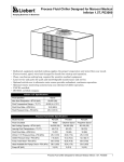
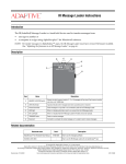
Ground Control Cabinet
Service Manual
P1507-12/336
Manual part number: 1507610801
Revision date: December 3, 2009
© Copyright 2009 Adaptive Micro Systems LLC. All rights reserved.
Adaptive Micro Systems
7840 North 86th Street
Milwaukee, WI 53224 USA
414-357-2020
800-558-7022
414-357-2029 (fax)
http://www.adaptivedisplays.com
Adaptive is a regisered trademark of Adaptive Micro Systems. All other brand and product names are
trademarks or registered trademarks of their respective companies.
December 3, 2009
Contents
Introduction............................................................................ 2
Purpose.................................................................................................................................2
Revision history ....................................................................................................................2
Related documentation..........................................................................................................2
Safety information .................................................................................................................2
Preventing electrostatic discharge (ESD).................................................................2
Equipment symbols .................................................................................................2
Warnings, cautions, and notices ..............................................................................2
Lightning strike protection .......................................................................................3
EMI compliance.....................................................................................................................3
Cabinet components ................................................................. 4
Quick Start Guide .....................................................................................4
Overview ...............................................................................................................................4
Controller Block Diagram ......................................................................................................5
Control cabinet ......................................................................................................................6
LCD Ground Controller Detailed View....................................................................................7
Ground Controller PCB Assembly (PN 10950221) ................................................................9
LCD Ground Controller ........................................................................................................11
Rack mounted power strip (PN 46000032) .........................................................................11
Maintenance and Service ..........................................................12
Overview .............................................................................................................................12
Physical Inspection .............................................................................................................12
Ground Controller Board Replacement................................................................................13
Fan Replacement (PN 46008028SP) ...................................................................................15
Heater Replacement (PN 30676014SP) ..............................................................................15
Fan Thermostat Replacement (PN 41009072).....................................................................16
Heater Thermostat Replacement (PN 41009071) ................................................................17
Checking and Replacing the Fan Filter .................................................................................18
Fluorescent Lamp Replacement ..........................................................................................19
Transient Voltage Suppressors (TVS) (PN 30352001SP2)..................................................20
Rack Mounted Power Strip Replacement (PN 46000032)...................................................21
Front Access Full Matrix LED Sign Maintenance Manual (pn 1507610801)
1
Introduction—
Introduction
Purpose
This manual is intended as a guide for maintenance and repairs considered field serviceable.
This field service manual supplies technical information for service and technical personnel so that they can
maintain the equipment at the assembly but not the internal component level.
Revision history
Revision
Date
Notes
1507610801 rev A
November 12, 2009
Initial Release
Related documentation
Technical documentation can be found at Adaptive’s web site — www.adaptivedisplays.com/manuals/:
Part #
Manual title
Description
1507610701
28x72 Front Access Full Matrix LED
Sign Maintenance Manual
This manual explains how to maintain and service a
28x72 Front Access LED sign.
15075051DR
Control Cabinet Wiring Diagram
Wiring details for control cabinet.
15075052DR
Sign Wiring Diagram
Wiring details for sign.
15075053DR
LCD Pass Through Diagram
Wiring details for ground controller.
Preventing Electrostatic Discharge
Damage
Tech memo.
00-0005
Safety information
Preventing electrostatic discharge (ESD)
This equipment contains components that may be damaged by “static electricity”, or electrostatic discharge. To
prevent this from happening, be sure to follow the guidelines in Adaptive Tech Memo 00-0005, “Preventing
Electrostatic Discharge (ESD) Damage,” available on our Web site at http://www.adaptivedisplays.com.
Equipment symbols
Chassis ground
Warnings, cautions, and notices
Warnings, cautions, and notices are posted in appropriate locations throughout this manual.
Ground Control Cabinet Service Manual (PN 1507610801)
2
Introduction—
Lightning strike protection
A control cabinet bonded to an earth ground has a means of dissipating the high voltage and current from a
lightning strike. The resistance of the grounding electrode must be as low as possible. However, damage can
still occur to the cabinet’s electronic equipment from lightning voltage transients.
Though some surge protection is incorporated into the control cabinet, to protect a cabinet from high-voltage
lightning transients, surge protectors need to be installed in accordance with NEC Articles 280 and 285.
EMI compliance
This equipment has been tested and found to comply with the limits for a Class A digital device, pursuant to
Part 15 of the FCC Rules. These limits are designed to provide reasonable protection against harmful
interference when the equipment is operated in a commercial environment.
This equipment generates, uses, and can radiate radio frequency energy and, if not installed and used in
accordance with installation guidelines, may cause harmful interference to radio communications. Operation of
this equipment in a residential area is likely to cause harmful interference, in which case the user will be
required to correct the interference at his own expense.
3
Ground Control Cabinet Service Manual (PN 1507610801)
Cabinet components—Quick Start Guide
Cabinet components
Quick Start Guide
• Mounting the Ground Cabinet:
Mount cabinet to the pole using
straps (third-party supplied part) to
the three mounting brackets
provided.
• Electrical Connection: Connect
Control Center load center to 120/
240V single phase 40A service.
Connect sign to dual pole 30A
breaker.
• Communications Connection:
Connect communications cabling
between ground controller to sign
controller surge arrestors per
diagram at right. Ground controller
dipswitches should be set the same
as the dipswitches on the sign
controller for proper operation.
9
RED
BLACK
GREEN
WHITE
Sign Controller Surge Arrestor
(Located in Sign)
10
RED
BLACK
GREEN
WHITE
1
2
9
10
RED
BLACK
GREEN
WHITE
1
RED
BLACK
GREEN
WHITE
2
CONNECTS TO
SIGN
CONTROLLER(S)
CONNECTS TO
GROUND
CONTROLLER
Pass Through Ground
Controller
(Located in Ground Cabinet)
Overview
The control cabinet creates a secured on-site centralized location for service personnel to easily access the
sign’s networking and operating equipment. This section gives a brief description on each individual
component in the control cabinet and how to field replace each item.
Note:
Adaptive recommends all equipment documentation/manuals associated with the contents of the
control cabinet is kept inside the cabinet. Record all service/maintenance performed on the control
cabinet into the service log typically located in the document drawer.
WARNING! Hazardous voltage may be present in cabinet. Contact with high voltage may cause
death or serious injury. Always disconnect power to equipment prior to servicing.
Notice: Ensure the cabinet door is completely closed and secured.
Ground Control Cabinet Service Manual (PN 1507610801)
4
Cabinet components—Controller Block Diagram
Controller Block Diagram
Power Supply Fail Signals
Door Switch
Humidity Sensor
Display Boards
Light Sensors
SIGN
J6
P2
P3
J5
Breaker #2
J4
Controller
#1
Fan Status
Board
Relay #1
P1
Thermostat
J3
Fans
J2
P4
Relay #2
Heaters
RS422 Transmit/Receive
Ground Controller
RS422
Surge
RS422
Surge
GROUND
CONTROLLER
CABINET
J6
P2
Typically Local Access Port
(for Laptop Computer)
P3
J5
J4
Ground
Controller
Panel
P1
Central NTCIP Connection
J3
J2
Ethernet
5
Door
Switch
P4
Ground Control Cabinet Service Manual (PN 1507610801)
Cabinet components—Control cabinet
Control cabinet
The NEMA 3R rated cabinet enclosure is equipped with fan and heater controls to maintain environmental
conditions. Located inside the cabinet is a GFCI receptacle, fluorescent lamp, surge arrestor, and LCD
controller with terminal.
Fan Thermostat
Fan
(located inside top of cabinet)
Fluorescent lamp
(located inside top of cabinet)
Lifting eyelets
Cabinet door’s
locking arm
LCD display
LCD Controller
w/keyboard
GFCI outlet
Heater
control
Filter
(not installed
in view)
Rack Mounted
Power
Strip Documentation pouch
with service log
Heater
Load Center
Ground Control Cabinet Service Manual (PN 1507610801)
Document
Drawer
6
Cabinet components—LCD Ground Controller Detailed View
LCD Ground Controller Detailed View
A
B
D
C
E
The ground controller is password
protected. Contact Doug Spencer
(Oregon DOT) for login
credentials.
K
I
F
H
G
Ground control cabinet angled open view
D
E
J
7
Item
Name
Part #
A
GROUND CONTROL CABINET
—
B
ETHERNET SURGE
SUPPRESSOR
C
GROUND CONTROLLER
10950221
D
LCD MODULE SCREEN
15009308
Description
19" rack mounted ground controller cabinet.
1507101201 Protects an Ethernet data port from damaging surges.
The ground controller is connected to the NTCIP network and works in
conjunction with the sign controller board to control sign operation.
Refer to wiring diagram for the proper firmware part number to be loaded into this
assembly.
240 x 64 pixel LCD display.
Ground Control Cabinet Service Manual (PN 1507610801)
Cabinet components—LCD Ground Controller Detailed View
E
CABINET DOOR
F
MODEM
10519024
G
POWER SUPPLY
40656304
—
Cabinet door with lock. 5/32 Hex tool required to open the cabinet.
Modem is configured for 9600 baud from the factory. It is used to interface via PN
43312001 (Telephone Surge Arrestor) to the DOT-supplied telephone line for
control of the ground controller.
Meanwell SP-200-12 switching power supply, 12VDC output:
Power indicator
Voltage output
adjustment
12VDC outputs
AC power in:
GND, Neutral, and
Hot connections
H
SURGE ARRESTOR
I
GROUND LUG
J
KEYBOARD
10729911
The keyboard is used to type commands into the ground controller.
K
SURGE PROTECTOR
30350018
30350019
Protects the RS422 transmit/receive connection from a peak surge current of
10kA. There are two surge protectors: one in the sign and the other in the ground
controller cabinet:
30352001
—
Protect systems against transient surge events.
Connects to a customer supplied ground.
&)%,$
3)$%
[
5NPROTECTED0AIR [
5NPROTECTED0AIR
Ground Control Cabinet Service Manual (PN 1507610801)
%,%#42/.)#3
3)$%
[ 0ROTECTED0AIR
[ 0ROTECTED0AIR
Pins 1 and 10 are the
same point electrically.
8
Cabinet components—Ground Controller PCB Assembly (PN 10950221)
Ground Controller PCB Assembly (PN 10950221)
K
L
M
N
P
O
O
Q
R
S
J
I
T
H
G
F
E
U
D
C
B
A
V
Item A and G jumpers must match for proper operation and communication between the controllers.
Item
A
9
PCB label
JP7 TO JP11
Name
Description
COMM PORT
SELECTION
JUMPERS FOR J6
AND P2
Set to RS485 with termination. Jumper settings must match Item G jumpers.
Jumper configured for RS422. This port used for the communications to sign
controller.
RS232
RS485
with termination
B
J6
COMM PORT
C
J5 A/INPUT
ANALOG INPUTS
D
J4 D/INPUT
DIGITAL INPUTS
E
P1
RS232 PORT
Central control port.
F
S1
DIP SWITCHES
Dipswitch for addressing the ground controller.
G
JMP2 TO JMP6
H
J3
COMM PORT
I
J2
DIGITAL OUTPUTS
J
JMP1
K
J1
POWER
CONNECTOR
Connects to Power Panel for DC Power.
L
P4
COMM PORT
Connects to a local laptop or debug port.
RS485
without termination
Refer to jumper termination settings for Item A; these settings must match on the
ground controller for proper operation and communication between the controllers.
Not used.
Set to DC.
Ground Control Cabinet Service Manual (PN 1507610801)
Cabinet components—Ground Controller PCB Assembly (PN 10950221)
M
BAT1
MEMORY BACKUP 3V lithium battery (Panasonic CR2032 or equivalent).
N
LED1 TO LED4
DIAGNOSTIC LEDS • LED1—Controller Heartbeat.
• LED2—Flashes when receiving communications from Central/Local port P1 or P3.
• LED3—Flashes when receiving communications from menu processor.
• LED4—Flashes with communications to and from sign controller #3.
O
J5
P
PROGRAMMING
PORT
Used to program the controller with a rabbit programming cable.
ETHERNET PORT
Ethernet 10-BASE T connection
Q
J10
LCD HEADER
R
S2 RESET
CONTROLLER
RESET SWITCH
S
J11
LCD BACKLIGHT
T
P3
COMM PORT
Typically used for a local laptop top connection.
U
P2
COMM PORT
Not used.
V
J13
PS/2 KEYBOARD
Connects to the keyboard.
Used to do a soft reset on the controller.
Ground Control Cabinet Service Manual (PN 1507610801)
10
Cabinet components—LCD Ground Controller
LCD Ground Controller
The function of this assembly is to provide an LCD interface for service personnel. The ground controller is
used in a passthrough mode to communicate to the sign controller; i.e., all data that is sent to ethernet and
RS232 is passed to the sign controller. All responses from the sign controller are directed back to the
appropriate port. The ground controller communicates to the sign controller via NTCIP protocol. The
communications use the J6 port on the ground controller and the J3 port on the sign controller, because these
support RS422. Both sign and ground controller must be set to the same serial address. See the table
labelled“DIP switch addressing” on page 14 for the proper settings.
Rack mounted power strip (PN 46000032)
The rack mounted power strip with 12 NEMA 5-15R receptacles (2 front and 10 rear) provides additional
electrical outlets and surge protection for the addition of electrical components contained inside the control
cabinet. The power strip features front panel LED status indicators, lighted ON/OFF switch, and a 15 amp
circuit breaker.
ON/OFF lighted power
switch with transparent
locking cover
Rack mounting
bracket
11
Front
receptacles
Status LEDs
15 amp circuit
breaker
AC Power
cord
Rear
receptacles
Ground Control Cabinet Service Manual (PN 1507610801)
Maintenance and Service—Overview
Maintenance and Service
Overview
The following parts can be serviced and maintained as needed.
Part
Suggested Interval
Page
Ground Controller
6 months
13
Fan
6 months
15
Heater
6 months
15
Fan Thermostat
6 months
16
Heater Thermostat
6 months
17
Fan Filter
6 months
18
Fluorescent Light
6 months
19
Transient Voltage Suppressors (TVS)
6 months
20
Rack Mounted Power Strip
6 months
21
WARNING! Hazardous voltage. Contact with high voltage may cause death or serious injury. Always
disconnect power to unit prior to servicing.
WARNING! Failure to properly ground the control cabinet could result in elevated voltage from
lightning entering the cabinet seeking a path to earth. The high voltage can result in electric shock,
fires, and the destruction of the cabinet from lightning.
Physical Inspection
A physical inspection of the cabinet’s exterior and interior should be performed every 6 months.
Exterior inspection
• Check for any physical damage to the exterior of the cabinet.
• Check for loose nuts, bolts, hinges, doors, and so on.
• Check the exterior electronics for foreign debris and general cleanliness.
• Check the exterior of the cabinet for general cleanliness.
Interior inspection
• Check for any physical damage to the interior of the cabinet.
• Check for loose nuts, bolts, hinges, doors, and so on.
• Check the interior electronics for foreign debris and general cleanliness.
• Check the interior of the sign for general cleanliness.
• Check that the cabinet’s filters and vents are clear of debris.
Ground Control Cabinet Service Manual (PN 1507610801)
12
Maintenance and Service—Ground Controller Board Replacement
Ground Controller Board Replacement
WARNING! Hazardous voltage. Contact with high voltage may cause serious injury or death. Always
disconnect power to unit prior to servicing.
➩ To replace the ground controller board
1. Switch all control cabinet breakers to the OFF position, except the breaker for the lights.
2. Locate ground controller; see “Inside views” on page 18 for the location.
3. Set the DIP switches and jumpers (JMP2-6 and JP7-11) on the replacement board to match the settings on
the board being replaced. At least one dip switch must be on for the controller to function properly.
Note: The sign controller’s and the ground controller’s dip switch addresses must match for them to
communicate.
Figure 1.
Ground Controller panel DIP switch settings.
Notice:
Turning all dip switches off will cause
the controller to lose its IP, Subnet
mask, and Ethernet routing
information.
DIP switch addressing
DIP switches #1 through #8 = address
Dipswitch
Address
1
1
2
2
3
4
4
8
5
16
6
32
7
64
8
128
ON
4. Disconnect all the cables from the controller board to be replaced.
5. Remove the six screws (see Figure 2) that hold the controller board to the panel. Remove the controller
board from the sign.
Figure 2.
Locations of the screws securing the controller board to the panel.
6. Fasten the new controller board to the ground controller plate.
7. Reconnect all the cables to the new controller board.
8. Apply power to the controller plate.
13
Ground Control Cabinet Service Manual (PN 1507610801)
Maintenance and Service—Ground Controller Board Replacement
➩ If applicable, change the IP address for the new ground controller board
To assign an IP address, the IP Set Utility program must be installed on the computer that will be
communicating to the sign. Contact Adaptive Technical Services at (800) 558-7022 or (414) 357-2020 if you do
not have this program.
Note: If the IP address on the ground controller is changed, the ground controller IP address must be changed
to match the new address.
1. Using a null modem cable, connect a laptop computer to the controller board at P3 (next to the Reset
button). See “Ground Controller PCB Assembly (PN 10950221)” on page 9 for the P3 location.
2. Open IP Set Utility program — select Start > Programs > IPSetUtility > IP Set Utility.
3. Enter the appropriate information in the IP Set Utility window (See Figure 3).
Note: If the controller is operational (LED 1 is normally flashing), use Get to verify if the sign’s IP address can be
retrieved.
Figure 3.
Setting the IP address for the controller.
Important: Verify that the device address matches the controller address on the SW1 dip switch
Get retrieves IP information
from the sign
Set assigns IP information to
the sign
Get Module Info retrieves
information about the sign
The status bar displays important
information about the status of
the information being assigned to
or retrieved from the sign
DIP switch addressing
DIP switch positions
Equivalent decimal values
1
1
2
2
3
4
4
8
5
16
6
32
7
64
8
128
Example:
If SW1 has position 1
and position 4 on,
then it is set to
address 9
4. Click Set to set the IP address (each sign must have a unique IP address).
5. After the IP address is set, detach the computer from the controller board.
6. Reset the controller and verify operation of controller.
Ground Control Cabinet Service Manual (PN 1507610801)
14
Maintenance and Service—Fan Replacement (PN 46008028SP)
Fan Replacement (PN 46008028SP)
WARNING! Hazardous voltage. Contact with high voltage may cause serious injury or death. Always
disconnect power to unit prior to servicing.
Fans are operated via a thermostat switch. This is located on the top above the rear door.
The thermostat is adjustable from 80°F to 170°F. The factory default is set at 120°F.
To remove failed fan
1. Disconnect AC to control center.
2. Open the doors to the control center.
3. Disconnect AC cord to fan.
4. Remove the four 6/32 X 2.0" screws and fan guard securing fan on top of enclosure.
5. Discard old fan per manufacturers recommendations.
To install replacement fan
1. Place fan guard on replacement fan.
2. Install the fan and fan guard with the four previously removed 6/32 X 2.0" screws. Do not over tighten
- 10-15inlbs.
3. Reinstall the AC cord to fan.
4. Close control center.
5. Re-apply AC to control center.
6. Verify function of fans.
Heater Replacement (PN 30676014SP)
WARNING! Hazardous voltage. Contact with high voltage may cause serious injury or death. Always
disconnect power to unit prior to servicing.
➩ To replace a heater
1. Disconnect AC to control cabinet.
2. Open the doors to the control cabinet.
3. Remove the cover from the heater using a phillips screw driver.
WARNING! Do not touch the heater. The surface is hot and may result in injury.
4. Remove the 1/4-20 bolts securing the heater to the mounting bracket.
5. Disconnect the two 10-32 screws connecting the heater to AC power.
6. Attach wiring to the new heater and secure the heater to the heating bracket with the 1/4-20 bolts.
Note: Make sure the wiring does not come in contact with the heater or cover. Wiring can be
connected to any post on heater (no polarization).
7. Reinstall cover with 6-32 screw previously removed.
8. Re-apply AC to heater and verify operation.
15
Ground Control Cabinet Service Manual (PN 1507610801)
Maintenance and Service—Fan Thermostat Replacement (PN 41009072)
Fan Thermostat Replacement (PN 41009072)
WARNING! Hazardous voltage. Contact with high voltage may cause serious injury or death. Always
disconnect power to unit prior to servicing.
Fans are operated via a thermostat switch. This is located on the top above the rear door.
The thermostat is adjustable from 80°F to 170°F. Factory default is 120°F.
To remove a failed fan thermostat
1. Disconnect AC to control center.
2. Open the rear door to the control center.
3. Disconnect AC connections to fan thermostat.
4. Remove the two 6/32 X 0.5” screws securing the thermostat to the mounting plate at the top of the
control center.
5. Discard old fan thermostat per manufacturers recommendations.
To install a replacement fan thermostat
1. Install the fan thermostat with the two previously removed 6/32 X 0.5" screws. Do not over tighten - 10
to 15inlbs.
2. Reinstall the fan thermostat AC connections. There is no polarization to the thermostat connections.
Do not over tighten - 8 to 10inlbs.
3. Set thermostat to 120°F.
4. Close control center.
5. Re-apply AC to control center.
6. Verify function of fans.
Ground Control Cabinet Service Manual (PN 1507610801)
16
Maintenance and Service—Heater Thermostat Replacement (PN 41009071)
Heater Thermostat Replacement (PN 41009071)
WARNING! Hazardous voltage. Contact with high voltage may cause serious injury or death. Always
disconnect power to unit prior to servicing.
Heaters are operated via a thermostat switch. This is located on the side wall of the control cabinet.
The thermostat is adjustable from -10°F to 100°F. Factory default is -10°F.
This switch is Grainger 2E816 or equivalent.
To remove a failed heater thermostat
1. Disconnect AC to control center.
2. Open the door to the control center.
3. Open heater thermostat.
4. Disconnect AC connections to heater thermostat. Red and black are connected. Blue is capped with a
wire nut.
5. Remove the four 6/32 X 0.5” screws securing the thermostat to the mounting plate.
6. Discard old heater thermostat per manufacturers recommendations.
To install a replacement heater thermostat
1. Install the heater thermostat with the four previously removed 6/32 X 0.5" screws. Do not over tighten
- 10 to 15inlbs.
2. Reinstall the heater thermostat AC connections with the wire nuts provided with the replacement
heater thermostat. Verify the wire nut is installed on the blue wire. Verify the black and red are installed
as before.
3. Reinstall the cover on the thermostat.
4. Set thermostat to -10°F.
5. Close control center.
6. Re-apply AC to control center.
7. Verify function of heater.
17
Ground Control Cabinet Service Manual (PN 1507610801)
Maintenance and Service—Checking and Replacing the Fan Filter
Checking and Replacing the Fan Filter
The first indication of excessively clogged fan filters is usually a gradual increase of temperature within the
cabinet. It is generally recommended to check and, if filters are clogged, replace filters every 6-12 months.
The fan filter is located in the door. Measurements of the filter are 12” X 12” X 1” and can be replaced with
Grainger #6B831 or equivalent.
To access and remove the fan filter:
1. Disconnect AC to control center.
2. Open the doors to the control center.
3. The filter holder is located on the bottom of the door.
4. Turn the holding latches so they are out of the way of the filter.
5. Pull the filter out and up to remove.
To install the replacement filter:
1. Install the filter into the holder by inserting the bottom end first.
2. Insert the filter fully into the holder, and turn the filter holders down to secure it in place.
3. Close control center.
4. Re-apply AC to control center.
Ground Control Cabinet Service Manual (PN 1507610801)
18
Maintenance and Service—Fluorescent Lamp Replacement
Fluorescent Lamp Replacement
WARNING! Hazardous voltage. Contact with high voltage may cause serious injury or death. Always
disconnect power to unit prior to servicing.
The fluorescent lighting tube is AMS #50600013SP, Grainger #2V429 or equivalent.
The light fixture is AMS #50600012, Grainger 3GA54, or equivalent.
To remove the fluorescent lighting tube:
1. Disconnect AC to control center
2. Open the rear door (the door that hinges on the left) to the control center.
3. The lighting tube is located at top of control center. Twist and remove the failed tube.
4. Install the replacement tube by sliding in contact and twisting.
5. Pull gently on tube to verify that it is securely installed.
6. Re-apply AC to control center.
7. Verify function of replacement lighting tube.
19
Ground Control Cabinet Service Manual (PN 1507610801)
Maintenance and Service—Transient Voltage Suppressors (TVS) (PN 30352001SP2)
Transient Voltage Suppressors (TVS) (PN 30352001SP2)
The TVS devices that are installed on the load center in the control cabinet are used to suppress voltage
spikes and surges.
These TVS's have an LED indicator on them which indicates if they are operating or not. If the LED is green
and lit, the TVS’s are functioning as required. If it is out, the device has failed and should be replaced.
WARNING! Hazardous voltage. Contact with high voltage may cause serious injury or death. Always
disconnect power to unit prior to servicing.
To remove the TVS devices:
1. Disconnect AC to control cabinet prior to servicing the TVS’s. Remove load center cover.
2. Disconnect the two black and white wires from load center.
3. Remove the TVS from load center by loosening nut.
4. Dispose of per manufacturers recommendations.
To install a replacement TVS:
1. Remove the nut from the replacement TVS.
2. Install replacement TVS into the failed location on load center.
3. Tighten nut 1/4" turn past flush.
4. Label white wire with the “GND” label provided with replacement TVS.
5. Label one black wire with the “NEUT” label provided with replacement TVS.
6. Label one black wire with the “HOT” label provided with replacement TVS.
7. Install the white wire in ground bar in load center.
8. Strip wire 1.5". Install the HOT black wire onto the main lug of the load center.
9. Install the NEUT black wire into neutral bar of load center.
10. Re-Install the load center cover.
11. Reapply AC power to the control cabinet.
12. Verify that the green LED is lit on the TVS that was replaced.
Ground Control Cabinet Service Manual (PN 1507610801)
20
Maintenance and Service—Rack Mounted Power Strip Replacement (PN 46000032)
Rack Mounted Power Strip Replacement (PN 46000032)
WARNING! Hazardous voltage. Contact with high voltage may cause serious injury or death. Always
disconnect power to unit prior to servicing.
To remove the rack mounted power strip:
1. All components that are plugged into the power strip must be turned off before the components are
unplugged from the power strip.
2. Disconnect all cables connected to the rack mounted power strip.
3. Disconnect AC to ground cabinet.
4. Disconnect from breaker.
5. Dispose of the defective power strip according to the manufacturer’s guidelines.
To install the replacement rack mounted power strip:
1. Mount replacement power strip in location of failed strip.
2. Plug in all component power cords that were previously unplugged from the power strip.
3. Strip 12 inches of jacket and remove power cable connector.
4. Wire into breaker as shown in wiring diagram for ground cabinet.
21
Ground Control Cabinet Service Manual (PN 1507610801)