1
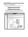
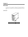
()
Service Guide
EXPRESS5800/120Mf
■
■
■
■
■
■
■
■
■
■
■
■
■
■
■
■
■
■
■
■
■
■
■
■
■
■
■
■
■
■
■
■
■
■
■
■
■
■
■
■
■
■
■
■
■
■
■
■
■
■
■
■
■
■
■
■
■
■
■
■
■
■
■
■
■
■
■
■
■
■
■
■
■
■
■
■
■
■
■
■
■
■
■
■
■
■
■
■
■
■
■
■
■
■
■
■
■
■
iii
CONTENTS
Preface...........................................................................................................................................v
Safety Indications .......................................................................................................................vi
Notes on Using the Server.............................................................................................. 1-1
About Warning Labels ..................................................................................................................1-1
Safety Notes..................................................................................................................................1-2
General .....................................................................................................................................1-2
Power Supply and Power Code Use .........................................................................................1-3
Installation, Relocation, Storage, and Connection....................................................................1-5
Cleaning and Working with Internal Devices...........................................................................1-6
During Operation......................................................................................................................1-7
For Proper Operation ....................................................................................................................1-8
Transfer To Third Party.................................................................................................................1-9
NEC Express server ............................................................................................................1-9
Provided software ...............................................................................................................1-9
Disposal And Consumables ........................................................................................................1-10
Advice for Health..............................................................................................................1-11
User Support ...............................................................................................................................1-12
Overview........................................................................................................................... 2-1
Appearance ...................................................................................................................................2-1
Specifications................................................................................................................................2-2
Unit Configuration ........................................................................................................... 3-1
Specifications................................................................................................................................3-1
Names and Functions of Components ..........................................................................................3-3
Connector location........................................................................................................................3-3
Block diagram...............................................................................................................................3-3
Cable connection list.....................................................................................................................3-4
Troubleshooting............................................................................................................... 4-1
POST Error Message List .............................................................................................................4-1
Error Beep Codes..........................................................................................................................4-8
POST Codes..................................................................................................................................4-9
Preventive Maintenance.................................................................................................. 5-1
Periodic Maintenance ...................................................................................................................5-1
Maintenance by User ....................................................................................................................5-1
Installing Internal Optional Devices............................................................................... 6-1
Preparing for Installation and Removal ........................................................................................6-1
Power Supply Cage.......................................................................................................................6-2
Removing the Power supply unit (CAGE)..........................................................................6-2
Installing the Power supply unit (CAGE) ...........................................................................6-3
Fan Unit ........................................................................................................................................6-4
Removing the FAN unit ......................................................................................................6-4
Installing the FAN unit........................................................................................................6-4
Motherboard .................................................................................................................................6-5
Removing the Motherboard ................................................................................................6-5
Installing the New Motherboard .........................................................................................6-5
Making Backup Copies of NVRAM Information ...............................................................6-6
Restoring NVRAM Information .........................................................................................6-7
If the System is Unable to Make Backup Copies of NVRAM Information ........................6-9
iv
Updating SDR FW ............................................................................................................6-11
Mounting a Heat Sink on the CPU....................................................................................6-11
Removing the Motherboard ..............................................................................................6-11
How to Attach the Motherboard....................................................................................... 6-14
SCSI Back Panel (SCSI-B.P) & SAF-TE Board........................................................................ 6-16
Removing the SCSI-B.P. .................................................................................................. 6-16
Installing the SCSI Back Panel ........................................................................................ 6-17
CD-ROM Drive ......................................................................................................................... 6-18
Removing the CD-ROM Drive ........................................................................................ 6-18
Floppy Disk Drive ..................................................................................................................... 6-19
Removing the FDD .......................................................................................................... 6-19
FRONT Bezel ............................................................................................................................ 6-20
Removing the Front Bezel................................................................................................ 6-20
Front Sub Bezel ......................................................................................................................... 6-21
Removing the Front Sub Bezel ........................................................................................ 6-21
Front Panel Board ...................................................................................................................... 6-22
Removing the Front Panel Board ..................................................................................... 6-22
Other Option Parts ..................................................................................................................... 6-23
Rack Mount Conversion ............................................................................................................ 6-23
Maintenance Parts ........................................................................................................... 7-1
Maintenance Parts List................................................................................................................. 7-1
Notes ................................................................................................................................. 8-1
About the Use of Screws.............................................................................................................. 8-1
About the Transporting ................................................................................................................ 8-1
Preface v
Preface
Welcome to the Express5800/120Mf server Service Guide. This manual describes the
maintenance work necessary for the Express5800/120Mf basic processing unit. Keep this guide
at hand for quick reference at any time it may be required.
Read the section “Safety Indications” first, then proceed to “Notes On Using The Nec Express
Server”.
vi Preface
Safety Indications
Follow the instructions given in this service guide for proper operation and safe use
of the NEC Express5800.
This guide describes server components with possible danger, hazards that may be
caused by ignoring warnings, and preventive actions against such hazards.
Server components with possible danger are indicated with a warning label placed
on or around them. They are also described in this guide.
In the user’s guide and on warning labels, “WARNING” or “CAUTION” is used to
indicate a degree of danger. These terms are defined as follows:
WARNING
CAUTION
Indicates the presence of a hazard that may cause loss of life or serious
personal injury if the instruction is ignored.
Indicates the presence of a hazard that may cause minor personal injury,
including burns or property damage, if the instruction is ignored.
Precautions and notices against hazards are presented with one of the following 3
symbols. The individual symbols are defined as follows:
This symbol indicates the presence of a hazard if the instruction is
ignored. An image in the symbol illustrates the hazard type.
(Attention)
This symbol indicates prohibited actions. An image in the symbol
illustrates a particular prohibited action. (Prohibited Action)
This symbol indicates mandatory actions. An image in the symbol
illustrates a mandatory action to avoid a particular hazard.
(Mandatory Action)
(Example)
Symbol to draw attention
Term indicating a degree of danger
CAUTION
Symbol indicating a
prohibited action (may not
always be indicated)
Do not touch components in the NEC Express server while
they are hot.
Components (e.g., especially hard disk drive) in the server are
hot immediately after the power is turned off. Mount/dismount
components only when they are cool.
Contents of a danger
Chapter 1
Notes on Using the Server
This chapter includes useful information for proper and safe operation of the NEC Express server.
ABOUT WARNING LABELS
The warning label is attached to components with possible danger or their vicinity in the NEC
Express server to inform the user that a hazardous situation may arise when operating the server.
(Do not take off any label or soil it.)
If you find any label unattached, almost peeled off, or soiled, making the warning illegible, contact
your sales agent.
1-2 Notes on Using the Server
SAFETY NOTES
This section provides notes on using the NEC Express server safely. Read this section carefully
to ensure proper and safe use of the server. For symbols, see "SAFETY INDICATIONS"
provided earlier.
General
WARNING
Do not use the NEC Express server for services involving human lives or
requiring high reliability.
The NEC Express server is not intended to be used with or control facilities or
devices concerning human lives, including medical devices, nuclear facilities
and devices, aeronautics and space devices, transportation facilities and
devices; and facilities and devices requiring high reliability. NEC assumes no
liability for any accident resulting in personal injury, death, or property damage
if the NEC Express server has been used in the above conditions.
Do not use the NEC Express server if any smoke, odor, or noise is present.
If smoke, odor, or noise is present, immediately turn off the POWER switch
and disconnect the power plug from the outlet, then contact your sales agent.
Using the server in such conditions may cause a fire.
Keep needles or metal objects away from the NEC Express server.
Do not insert needles or metal objects into ventilation holes in the NEC
Express server or openings in the floppy disk or CD-ROM drive. Doing so
may cause an electric shock.
CAUTION
Keep water or foreign matter away from the NEC Express server.
Do not let any form of liquid (water etc.) or foreign matter (e.g., pins or paper
clips) enter the NEC Express server. Failure to follow this warning may
cause an electric shock, a fire, or a failure of the server. When such things
accidentally enter the server, immediately turn off the power and disconnect
the power plug from the outlet. Do not disassemble the server. Contact
your sales agent.
1-3 Notes on Using the Server
Power Supply and Power Code Use
WARNING
Do not hold the power plug with a wet hand.
Do not disconnect/connect the plug while your hands are wet. Failure to
follow this warning may cause an electric shock.
Do not connect the ground wire to a gas pipe.
Never connect the ground wire to a gas pipe. Failure to follow this warning
may cause a gas explosion.
CAUTION
Plug in to a proper power source.
Use a proper wall outlet. Use of an improper power source may cause a fire
or a power leak.
Do not install the NEC Express server where you need an extension cord.
Use of a cord that does not meet the power specifications of the NEC Express
server may heat up the cord and cause a fire.
Do not connect the power cord to an outlet that has an illegal number of
connections.
The electric current exceeding the rated flow overheats the outlet, which may
cause a fire.
Insert the power plug into the outlet as far as it goes.
Heat generation resulting from a halfway inserted power plug (imperfect
contact) may cause a fire. Heat will also be generated if condensation is
formed on dusty blades of the halfway inserted plug, increasing the possibility
of fire.
1-4 Notes on Using the Server
CAUTION
Use the authorized power cord only.
Use only the power cord that comes with the NEC Express server. Use of an
unauthorized power cord may cause a fire when the electric current exceeds
the rated flow.
Also, observe the following to prevent an electric shock or fire caused by a
damaged cord.
• Do not stretch the cord harness.
•
Do not pinch the power cord.
•
Do not bend the power cord.
•
Keep chemicals away from the power cord.
•
Do not twist the power cord.
•
Do not place any object on the power cord.
•
Do not bundle power cords.
•
Do not alter, modify, or repair the power cord.
•
Do not secure the power cord with staples or equivalents.
•
Do not use any damaged power cord. (Replace a damaged power cord
with a new one of the same specifications. Ask your sales agent for
replacement.)
1-5 Notes on Using the Server
Installation, Relocation, Storage, and Connection
CAUTION
Never attempt to lift the NEC Express server only by yourself.
The NEC Express server weighs up to 44 kg (depending on its hardware
configuration). Carrying the server only by yourself may strain your back.
Hold the server firmly by its bottom with another person to carry it. Do not
hold the front door to lift the server. The front door may be disengaged from
the server, causing personal injury.
Do not install the NEC Express server in any place other than specified.
Do not install the NEC Express server in the following places or any place
other than specified in this User's Guide. Failure to follow this instruction may
cause a fire.
! a dusty place
! a humid place such as near a boiler
! a place exposed to direct sunlight
! an unstable place
Do not connect any interface cable with the power cord of the NEC Express
server plugged to a power source.
Make sure to power off the NEC Express server and unplug the power cord
from a power outlet before installing/removing any optional internal device or
connecting/disconnecting any interface cable to/from the server. If the NEC
Express server is off-powered but its power cord is plugged to a power source,
touching an internal device, cable, or connector may cause an electric shock
or a fire resulted from a short circuit.
Do not use any unauthorized interface cable.
Use only interface cables provided by NEC and locate a proper device and
connector before connecting a cable. Using an authorized cable or
connecting a cable to an improper destination may cause a short circuit,
resulting in a fire.
Also, observe the following notes on using and connecting an interface cable.
! Do not use any damaged cable connector.
! Do not step on the cable.
! Do not place any object on the cable.
! Do not use the NEC Express server with loose cable connections.
1-6 Notes on Using the Server
Cleaning and Working with Internal Devices
WARNING
Do not disassemble, repair, or alter the NEC Express server.
Never attempt to disassemble, repair, or alter the NEC Express server on any
occasion other than described in this User's Guide. Failure to follow this
instruction may cause an electric shock or fire as well as malfunctions of the
server.
Do not look into the CD-ROM drive
A laser beam is used in the CD-ROM drive. Do not look into or insert a mirror
into the drive while the drive is powered. If a laser beam is caught in your
eyes, you may lose your eyesight (the laser beam is invisible).
Do not remove the lithium battery.
The NEC Express server contains a lithium battery. Do not remove the
battery. Placing the lithium close to a fire or in the water may cause an
explosion.
When the server does not operate appropriately due to the dead lithium
battery, contact your sales agent. Do not disassemble the server to replace
or recharge the battery by yourself.
Disconnect the power plug before cleaning the NEC Express server.
Make sure to power off the NEC Express server and disconnect the power
plug from a power outlet before cleaning or installing/removing internal
optional devices. Touching any internal device of the NEC Express server
with its power cord connected to a power source may cause an electric shock
even of the NEC Express server is off-powered.
Disconnect the power plug from the outlet occasionally and clean the plug with
a dry cloth. Heat will be generated if condensation is formed on a dusty plug,
which may cause a fire.
CAUTION
High temperature
Immediately after the NEC Express server is powered off, its internal
components such as hard disks are very hot. Leave the server until its
internal components fully cool down before installing/removing any
component.
Make sure to complete board installation.
Always install a board firmly. An incompletely installed board may cause a
contact failure, resulting in smoking or fire.
1-7 Notes on Using the Server
During Operation
CAUTION
Stay away from the fan.
Keep your hand or hair away from the cooling fan on the rear of the NEC
Express server. Failure to follow this warning may get your hand or hair
caught in the fan, resulting in injury.
Do not touch the NEC Express server when it thunders.
Disconnect the power plug from the outlet when a thunderstorm is
approaching. If it starts thundering before you disconnect the power plug, do
not touch any part of the NEC Express server including the cables. Failure to
follow this warning may cause a fire or an electric shock.
Keep any animal (pet) away from the NEC Express server.
Pet's discharges or fur may enter the NEC Express server and cause a fire or
electric shock.
Do not place any object on top of the NEC Express server.
The NEC Express server may fall and cause property damage to the
surroundings.
Do not leave the NEC Express server with its CD-ROM tray ejected.
Dust may enter the server through openings and cause malfunctions of the
NEC Express server. Any person may also bump it and get injured.
Take off the headset before connection.
Make sure to take off the headset before plugging it to the headset jack.
Failure to follow this instruction may hurt your ears. Make also sure to turn
down the volume before connection.
Do not use a cellular phone or pager around the NEC Express server.
Turn off the cellular phone or pager. Radio interference may cause
malfunctions of the NEC Express server.
1-8 Notes on Using the Server
FOR PROPER OPERATION
Observe the following notes for successful operation of the NEC Express server. Use of the NEC
Express server ignoring the notes will cause malfunctions or failures of the server.
!
Install the NEC Express server in a place that meets requirements for successful operation.
For details, see Chapter 2, "Setting Up the Server."
!
Do not delete the hard disk partition exclusively provided for maintenance of the NEC
Express server although it may appear on the OS.
!
Make sure to power off the NEC Express server before connecting or disconnecting
cables between the server and peripheral devices.
!
Verify that the access lamp on the NEC Express server is unlit before turning off the
server or ejecting the floppy disk.
!
Do not turn on the server after plugging the power cord.
!
Do not turn off the server until the "NEC" logo and the some characters appear on the
screen.
!
When you have just turned off the NEC Express server, wait at least 30 seconds before
turning it back on.
!
Turn off the power and unplug the power cord from the outlet before relocating the NEC
Express server.
!
You may use a software command to eject the tray or a media from the CD-ROM drive or
an optional device, for example a DAT, installed in the 5.25-inch device bay, respectively.
Make sure that the front door is open before ejecting the tray or media with a software
command. Running the command when the front door is closed will cause the tray or
media to hit against the front door, which may cause a hardware failure of the NEC
Express server as well as a software error.
!
Clean the NEC Express server on a regular basis. (See Chapter 5 for cleaning.)
Regular cleaning proactively prevents various failures of the server.
!
Lightning may cause a momentary voltage drop. To prevent this problem, it is
recommended to use an uninterruptible power supply unit.
!
Make sure to use optional devices supported by the NEC Express server. Some
non-supported devices may be physically installed/connected but cause failures of the
server as well as a malfunction of the server.
!
NEC recommends you use NEC's genuine products. Some third-party products claim
that they support the NEC Express server. However, repair of the server due to a failure
or damage resulted from use of such third-party products will be charged.
1-9 Notes on Using the Server
TRANSFER TO THIRD PARTY
The following must be observed when you transfer (or sell) the server or software provided with
the server to a third party:
NEC Express server
Make sure to provide the User’s Guide along with the server to a third party.
Provided software
To transfer or sell any software application that comes with the NEC Express server to a third party,
the following requirements must be satisfied:
!
All provided software applications must be transferred and no backup copies must be
retained.
!
Transfer requirements listed in "Requirements for Software Use" that comes with each
software application must be satisfied.
!
Software applications that are not approved for transfer must be uninstalled before
transferring the NEC Express server.
1-10 Notes on Using the Server
DISPOSAL AND CONSUMABLES
!
Dispose the server, hard disk drives, floppy disks, CD-ROMs, and optional boards as
required by the local regulations. Ask your local government for details.
IMPORTANT: For disposal (or replacement) of the battery
on the motherboard of the NEC Express server, consult with
your sales agent.
!
The NEC Express server contains some components that are only good for a limited
period of time and require replacement, such as fans, internal batteries, the internal
CD-ROM drive, the floppy disk drive, and the mouse. For stable operation of the NEC
Express server, NEC recommends you replace these components on a regular basis.
Consult with your sales agent for replacement or the product lives.
WARNING
Do not remove the lithium battery.
The NEC Express server contains the lithium battery. Do not remove the
battery. Placing the lithium or nickel cadmium battery close to a fire or in the
water may cause an explosion.
When the server does not operate appropriately due to the dead lithium battery,
contact your sales agent. Do not disassemble the server to replace or
recharge the battery by yourself.
Mother board
1-11 Notes on Using the Server
Advice for Health
The longer you keep using the computer equipment, the more you become tired,
which may cause disorders of your body. When you use a computer, observe
the following to keep yourself from getting tired:
Good Working Posture
You have good posture if the following are satisfied when you use a computer:
•
You sit on a chair with your back straight.
•
Your hands are parallel with the floor when you put them on the
keyboard.
•
You look at the screen slightly lower than your eye height.
You have "good working posture" as described in the above when no part of
your body is under excess strain, in other words when your muscles are most
relaxed.
You have "bad posture" when you sit with your back hunched up or you operate
a display unit with your face close to the screen. Bad working posture may
cause eye strain or poor eyesight.
Adjustment of Display Unit Angles
Most display units are designed for adjustment of the horizontal and vertical
angles. This adjustment is important to prevent the screen from reflecting
bright lights and to make the display contents easy to see. You will not be able
to keep "good working posture" and you will feel more tired than you should if
you operate a display unit without adjusting horizontal and vertical angles.
Adjustment of Screen Brightness and Contrast
The display unit has brightness and contrast adjustment functions. The most
suitable brightness and contrast depend on the individual and the working
environment (well-lighted room or insufficient light). Adjust brightness and
contrast so that the screen will be easy to see. An extremely bright or dark
screen will give a bad effect to your eyes.
Adjustment of Keyboard Angle
The keyboard provided with the NEC Express server is designed for adjustment
of an angle. Adjust the keyboard angle at which the keyboard is easy to
operate. The adjustment assists in reducing strain on your shoulders, arms,
and fingers.
Cleaning of Equipment
Clean equipment regularly. It is difficult to see the display contents on a dusty
screen. Keeping equipment clean is also important for your sight.
Fatigue and Rest
If you feel tired, you should stop working and do light exercises.
1-12 Notes on Using the Server
USER SUPPORT
Before Asking for Repair, do the following when the NEC Express server appears to fail:
1.
Check if the power cord and the cables to other devices are properly connected.
2.
See Chapter 6 to find if your problem fits the description.
recommended measure for it.
3.
Check if the software required for operation of the NEC Express server is properly
installed.
If it does, take the
If the NEC Express server still appears to fail after you have taken the above actions, consult with
your sales agent immediately. Take notes on lamp indications of the server and alarm indications
on the display unit before consultation, which may provide a significant help to your sales agent.
Chapter 2
Overview
This manual describes the maintenance method for NEC Express5800/120Mf basic
processing unit. The explanation is for maintenance personnel who perform site
adjustment, periodic inspection, and repair of NEC Express5800/120Mf basic processing
unit.
APPEARANCE
External dimensions (WDH, mm)
321×675×450
Weight (kg : MAX)
23kg (Max 44kg)
2-2
Overview
SPECIFICATIONS
The table below lists the general specifications of the unit.
Major
Minor
classification classification
Input power
Power supply
Voltage
Frequency
Waveform
distortion
Power
consumption
Input current
Apparent power
Active power
Temperature and Temperature
humidity
Humidity
Noise
POWER level
Sound pressure
level
Standard
Remarks
Single phase, 2-pole grounding The power supply itself
is capable between 100
100 to 240 VAC±10%
to 240 VAC, however,
50±1 Hz or 60±1 Hz
the value at the left is
10%
used as a unit
specification.
5.3 A
AC100V
530 VA
520 W
10 to 35oC
No condensation is
allowed
20 to 80%RH
62.8 dB (operating)
60.9 dB (standby)
52.9 dB (operating)
51.7 dB (standby)
Chapter 3
Unit Configuration
SPECIFICATIONS
120Mf
CPU
Processor
FSB
Package
L3 Cache
Chipset
Memory
HDD
Max.
DIMM
ECC
Chipkill
SpareMem
Standard
Max.
HotPlug
IDE I/F
SCSI I/F
DiskArray
Non RAID
RAID
Internal
Max.
Ext.
LAN
Video (VRAM)
Standard (x48/Half Height)
5.25”
3* (One for CDROM)
3.5”
Standard: 5(1”) + Option 5(1”)
Slot
Total 6slots
(64bit/133MHz PCI-X x1, 64bit /100MHz PCI-X x2,
32bit/33MHz PCI x3)
I/O slot
Hot Plug
PCI
Front
I/O
interface
Rear
Power Supply(PS)
Redundant PS
Redundant FAN
Front
Switch
Rear
Front door Key
LED
Front
Rear
Chassis
(WxDxH)
2Way-Interleave
128/256/512MB/1GB DIMM
*Online Spare memory
Intel Alliance Carrier
Ultra320,10K/15Krpm, SCA2
Standard: 5 slots
Optional: 5 slots added HDD cage
For CD-ROM/DVD-ROM/DVD-RAM
On-Board (AIC7899W)
LL MegaRAID
On-Board, RemoteWakeUp
On Board, RageXL
3.5" (2mode) x1
CD-ROM
Device bay
512KB
Grand Champion-LE(REV A3.1)
6GB (6 DIMMs)
DDR266 SDRAM DIMM(Registered)
Yes
Yes
Yes
0GB
10 x 146GB+
U320 10Krpm 36GB/73GB/146GB
U320 15Krpm 36GB/73GB
Yes
Ultra ATA100 x1ch
Ultra320 SCSI x2ch
iROC
Option
4 boards
Option
10/100/1000BASE-T x2
640x480 ~ 1280x1024 (8MB)
FDD
Notes
Prestonia x 1-2
533MHz
FC-mPGA2
design
Standard CDROM:
*2 slots when rack conversion
Max. 2HDD cages
Ultra160 SCSI BP
No
Serial(DB9) x1*,USB x1
CRT x1, KB(PS/2) x1, Mouse(PS/2) x1,
USB x3,Serial(DB9) x2*,
Parallel x1, 1000BASE-T x2,
Ultra320 SCSI x1, ICMB x2(PCI slot option)
Hotswap 2+1 x 350W (PFC)
Yes (option)
Yes (standard)
Power, Sleep, Reset, Dump
No
Yes
Power/Sleep, System Status, HDD
LAN Link/Act. x2, UID
* Alternatively used
1 AC cable/1 Power Supply
Hotswapable
Hotswapable
LAN Link/Act. X2, LAN Speed x2, UID
Middle-Tower (321 x 675 x 450mm)
Rack conversion(5U)
3-2 Unit Configuration
NAMES AND FUNCTIONS OF COMPONENTS
Please refer to the User’s Guide.
CONNECTOR LOCATION
Please refer to the User’s Guide.
BLOCK DIAGRAM
See next page.
3-3 Unit Configuration
3-4 Unit Configuration
CABLE CONNECTION LIST
Chapter 4
Troubleshooting
If your NEC Express server does not operate as expected, read this chapter before
assuming a failure.
NOTE: Troubleshooting and POST error messages refer to
User Guides.
POST Error Message List
On-screen error message
Description
Cause
Action
0200
Failure Fixed Disk
Hard disk failure
1. Incorrect setting in
Setup
2. HDD failed
3. Motherboard failed
1. Check parameters
entered in Setup
2. Replace HDD
3. Replace Motherboard
0210
Stuck Key
Keyboard connection
error
Poor keyboard
connection
0211
0212
Keyboard error
Keyboard controller
Failed
Keyboard error
Keyboard controller
failure
Keybord failed
Keybord controller
failed
0213
Keyboard locked Unlock key switch
Monitor type does not
match CMOS - Run
SETUP
Keyboard is locked.
Keyboard is locked.
1. Disconnect and reconnect
keyboard.
2. Replace keyboard
3. Replace Motherboard
Check connection
1. Check connection
2. Re-Start
3. Replace Mother Board
Release Keyboard lock
System timer error
Real time clock error
A system timer error
A real-time clock error
0220
0230
0231
0232
0250
0251
0252
0260
0270
The monitor type is not Incorrect monitor type 1. Reset default values in
consistent with the
setting
Setup.
CMOS data.
2. Clear CMOS
DIMM failed
1. Replace DIMM
System RAM Failed System RAM error.
at offset
2. Replace Motherboard
Shadow Ram Failed at Shadow RAM error.
offset
Extended RAM Failed Extended RAM error.
at address line
NV-RAM battery
Replace Motherboard
System battery is dead The system battery is
- Replace and run
worn out.
SETUP
NVRAM failed
1. Reset Setup parameters
System CMOS
The system CMOS
checksum bad checksum is incorrect.
2. Replace Motherboard
Default configuration
used
Password cleared
Reset Setup parameters
Password checksum
The checksum of a
bad - Passwords
password is inaccurate.
cleared
Replace Motherboard
RTC failed
4-2 Troubleshooting
On-screen error message
Description
Cause
Action
0271
Check data and time
setting
The real-time clock
Unusual time setup of 1. Reset Setup parameters
time setting is incorrect. RTC
2. Replace Motherboard
0280
Previous boot
incomplete - Default
configuration used
Diskette drive A error
Diskette drive B error
Incorrect Drive A type
- run SETUP
Incorrect Drive B type
– run SETUP
System cache error Cache disabled
System Memory
exceeds the CPU's
caching limit.
EISA CMOS not
write able
DMA Test Failed
Software NMI Failed
The last boot is
imperfect.
Default value was set. Reset Setup parameters
A floppy disk A error
A floppy disk B error
Incorrect drive A type
FDD error
Replace FDD
Incorrect settings
Reset Setup parameters
02B0
02B1
02B2
02B3
02D0
02D1
02F4
02F5
02F6
02F7
Fail-safe Timer NMI
Failed
0611 IDE configuration
changed
0612 IDE configuration
error-device disabled
0613 COM A configuration
changed
0614 COM A config. errordevice disabled
0615 COM B configuration
changed
0616 COM B config. Errordevice disabled
0617 Floppy configuration
changed
0618 Floppy config. error device disabled
0619 Parallel port
configuration changed
061A Parallel port config.
error - device disabled
0B00 Rebooted during
BIOS boot at Post
Code
0B01 Rebooted during OS
boot.
Incorrect drive B type
A system cache error
The memory exceeds
the limit of the cache of
CPU.
It cannot write in EISA
CMOS.
DMA test error
Software NMI error
Fail-safe Timer error
The composition error
of IDE
The composition device
error of IDE
The composition error
of COM A
The composition device
error of COM A
The composition error
of COM B
The composition device
error of COM B
The composition error
of Floppy
The composition device
error of Floppy
The composition error
of Parallel port
The composition device
error of Parallel port
The system re-started
during BIOS boot
The system re-started
during OS boot
1. CPU failed
1. CPU Exchange
2. Motherboard failed 2. Replace Motherboard
Motherboard failed
Replace Motherboard
4-3 Troubleshooting
On-screen error message
0B02 Rebooted during OS
Runtime.
0B1B PCI System Error on
Bus/Device/Function
0B1C PCI Parity Error on
Bus/Device/Function
0B22 Processors are
installed out of order.
0B28 Unsupported
Processor detected on
Processor 1
0B29 Unsupported
Processor detect on
Processor 2
0B30 Fan 1 Alarm occurred.
0B31 Fan 2 Alarm occurred.
0B32 Fan 3 Alarm occurred.
0B33 Fan 4 Alarm occurred.
0B34 Fan 5 Alarm occurred.
0B35 Fan 6 Alarm occurred.
0B50 CPU #1 with error
taken off line
0B51 CPU #2 with error
taken off line
0B5F Forced to use
Processor with error
0B60 DIMM group #1 has
been disabled
0B61 DIMM group #2 has
been disabled
0B62 DIMM group #3 has
been disabled
0B70 The error occurred
during temperature
sensor reading.
0B71 System Temperature
out of the range.
0B74 The error occurred
during voltage sensor
reading.
Description
Cause
Action
Processor errors
1. Replace CPU
2. Replace Motherboard
The system re-started
during OS Running
A PCI system error
occurred on the bus,
device, or function.
A PCI parity error
occurred on the bus,
device, or function.
Failure of a processor
Unsupported processor
mounted as processor 1.
Unsupported processor
mounted as processor 2.
Fan errors
1. Fan is blocked
1. Check fan connection
2. Fan failed
2. Clean fan
3. Motherboard failed 3. Replace fan
4. Replace Motherboard
CPU #1 was degraded
due to an error detected
for CPU #1.
CPU #2 was degraded
due to an error detected
for CPU #1.
A CPU error was
detected.
1. CPU# 1 failed
1. Replace CPU #1
2. Motherboard failed 2. Replace Motherboard
1. CPU# 2 failed
1. Replace CPU #2
2. Motherboard failed 2. Replace Motherboard
A memory error was
detected. Memory #1 is
degraded.
A memory error was
detected. Memory #2 is
degraded.
A memory error was
detected. Memory #3 is
degraded.
An error was detected in 1. SMBus Device
the course of thermal
failed
error detection.
2. SMBus Cable
failed
A thermal error was
detected.
An error occurred while Motherboard failed
detecting the voltage.
1. Replace CPU
2. Replace Motherboard
1. Replace Memory #1
2. Replace Motherboard
1. Replace Memory #2
2. Replace Motherboard
1. Replace Memory #3
2. Replace Motherboard
1. Turn off AC
2. Check cable
3. Replace Motherboard
1. Clean fan
2. Replace fan
3. Replace boards
1. Turn off AC
2. Check connection of
internal cables
4-4 Troubleshooting
On-screen error message
Description
0B75 System Voltage out of A system voltage error
the range.
was detected.
Cause
Action
1. SMBus Device
failed
2. SMBus Cable
failed
1. SMBus Device
failed
2. SMBus Cable
failed
internal cables
3. Replace internal cables
4. Replace boards
0B78 The error occurred
during fan sensor
reading.
0B7C The error occurred
during redundant
power module
confirmation.
An error was detected
during fan sensor
reading.
The error was detected
while having constituted
the redundant power
supply.
0B7D The normal operation
can't be guaranteed
with use of only one
PSU.
0B80 BMC Memory Test
Failed.
0B81 BMC Firmware Code
Area CRC check
failed.
0B82 BMC core hardware
failure.
0B83 BMC IBF or OBF
check failed.
Power supply error
Basic power supply
composition required
for this equipment is not
filled.
BMC failed
A BMC device (chip)
failure
0B8A BMC SEL area full.
An opening is not in the
capacity of SEL.
BMC check was
interrupted temporarily.
BMC command access
failed.
Console redirection
cannot be carried out
(BMC Busy)
Console redirection
cannot be carried out
(BMC error)
Console redirection
cannot be carried out
(BMC Parameter error)
BMC failed
A BMC device (chip)
failure
0B8B BMC progress check
timeout.
0B8C BMC command
access failed.
0B8D Could not redirect the
console - BMC Busy 0B8E Could not redirect the
console - BMC Error 0B8F Could not redirect the
console - BMC
Parameter Error 0B90 BMC Platform
Information Area
corrupted.
Replace a power supply
1. Turn off AC and re-start
2. Replace Motherboard
Access to the BMC
address failed.
0B91 BMC update firmware
corrupted.
0B92 Internal Use Area of
BMC FRU corrupted
1. Turn off AC
2. Check cable
3. Replace Motherboard
An error of the SROM
that stores the chassis
information
0B93 BMC SDR Repository A BMC device (chip)
empty.
failure
1. SROM failed
2. BMC failed
BMC failed
1. Turn off AC and re-start
2. Replace Motherboard
4-5 Troubleshooting
On-screen error message
Description
Cause
Action
BMC failed
1. Turn off AC and re-start
2. Replace Motherboard
Turn off AC and
replace CPU#1
1. Turn off AC and re-start
2. Replace boards
0B94 IPMB signal lines do
not respond.
An SMC (Sattelite
Management
Controller) error
0B95 BMC FRU device
An error of the SROM
failure.
that stores the chassis
information
0B96 BMC SDR Repository The access error to
failure.
FMEM sector in which
SDR information was
stored
0B97 BMC SEL device
A BMC device (chip)
failure.
failure
0B98 BMC RAM test error.
0B99 BMC Fatal hardware
error.
0B9A Management
controller not
responding
0B9B Private I2C bus not
responding.
0B9C BMC internal
exception
0B9D BMC A/D timeout
error.
0B9E SDR repository
corrupt.
0B9F SEL corrupt.
0BB0 SMBIOS - SROM
data read error.
0BB1 SMBIOS - SROM
data checksum bad.
0BC0 POST detected startup
failure of 1st
Processor.
0BC1 POST detected startup
failure of 2nd
Processor.
0BD0 1st SMBus device
address not
acknowledged.
0BD1 1st SMBus device
Error detected.
0BD2 1st SMBus timeout.
BMC RAM error
BMC error
BMC error
It-less answers from
private I2 C bus
BMC error
BMC error
The error of BMC or
the data of SEL is
destroyed.
The error of BMC or
the data of SEL is
destroyed.
Incorrect SROM data
read
Incorrect SROM data
checksum
Processor 1 error
Turn off AC and replace
CPU#1
Processor 2 error
Turn off AC and replace
CPU#2
A device-less answers
to 1st SMBus access.
The error was detected
to 1st SMBus access
The timeout occurred to
1st SMBus access.
SMBus Access error
1. Turn off AC and re-start
2. Replace boards
3. Replace internal cables
4-6 Troubleshooting
On-screen error message
0BD3 2nd SMBus device
address not
acknowledged.
0BD4 2nd SMBus device
Error detected.
0BD5 2nd SMBus timeout.
0BD6 3rd SMBus device
address not
acknowledged.
0BD7 3rd SMBus device
Error detected.
0BD8 3rd SMBus timeout.
0BD9 4th SMBus device
address not
acknowledged.
0BDA 4th SMBus device
Error detected.
0BDB 4th SMBus timeout.
0BDC 5th SMBus device
address not
acknowledged.
0BDD 5th SMBus device
Error detected.
0BDE 5th SMBus timeout.
0BE8 IPMB device address
not acknowledged.
0BE9 IPMB device Error
detected.
0BEA IPMB timeout.
8100
8101
8102
8120
8121
Memory Error
detected in DIMM
group #1
Memory Error
detected in DIMM
group #2
Memory Error
detected in DIMM
group #3
Unsupported DIMM
detected in DIMM
group #1
Unsupported DIMM
detected in DIMM
group #2
Description
Cause
Action
A device-less answers
to 2nd SMBus access.
The error was detected
to 2nd SMBus access
The timeout occurred to
2nd SMBus access.
A device-less answers
to 3rd SMBus access.
The error was detected
to 3rd SMBus access
The timeout occurred to
3rd SMBus access.
A device-less answers
to 4th SMBus access.
The error was detected
to 4th SMBus access
The timeout occurred to
4th SMBus access.
A device-less answers
to 5th SMBus access.
The error was detected
to 5th SMBus access
The timeout occurred to
5th SMBus access.
A device-less answers IPMB Access error
to IPMB access
The error was detected
to IPMB access
The timeout occurred to
IPMB access.
DIMM error
A memory error was
detected.
Unsupported DIMM
was detected.
Replace two DIMMs.
4-7 Troubleshooting
On-screen error message
8122
8130
8131
8132
8140
8141
8142
8150
8160
8161
Unsupported DIMM
detected in DIMM
group #3
Mismatch DIMM
Type detected in
DIMM group #1.
Mismatch DIMM
Type detected in
DIMM group #2.
Mismatch DIMM
Type detected in
DIMM group #3.
DIMM group #1 with
error is enabled.
DIMM group #2 with
error is enabled.
DIMM group #3 with
error is enabled.
NVRAM Cleared By
Jumper
Mismatch Processor
Speed detected on
Processor 1
Mismatch Processor
Speed detected on
Processor 2
Description
Cause
Action
The type of DIMM is
not in agreement.
1. Check that DIMMs of the
same type are installed in
groups.
2. Replace DIMMs.
Failed DIMM in group
#1 was detected.
Failed DIMM in group
#2 was detected.
Failed DIMM in group
#3 was detected.
NVRAM was cleared
by jumper setup.
Replace both DIMMs.
The frequency of
processor 1 is not
correct.
The frequency of
processor 2 is not
correct.
Incorrect jumper
setting
Processor errors
Turn off power and change
the jumper setting back to
its default position.
4-8 Troubleshooting
Error Beep Codes
Beep
1-2-2-3
1-3-1-1
1-3-1-3
Error
ROM checksum error
DRAM refresh test error
Keyboard controller error
1-3-3-1
DIMM can not be detected
1-3-3-1
1-3-4-3
Memory check error
DRAM test low byte error
2-2-3-1
Unjust exception test error
1-2
Video configuration fails
1-2
OPTION ROM Checksum failure
Cause
FMEM checksum error
Memory refresh error
Keyboard controller
error
Memory not installed or
cannot write.
↑
Memory address signal
fault (low side)
Unjust exception
Expansion VGA BIOS
memory Deployment failure
Expansion ROM BIOS
memory Deployment failure
Troubleshooting
Replace MotherBoard
Replace DIMM
Replace MotherBoard
Check DIMM
Mounting or Replace
DIMM
↑
Replace MotherBoard
or DIMM
Replace MotherBoard
or CPU
Replace MotherBoard
or Graphic board
Replace MotherBoard
or Option board
4-9 Troubleshooting
POST Codes
The code displayed using the postcard is shown below.
CP
01
02
03
04
06
08
09
0A
0B
0C
0E
0F
10
11
12
13
14
16
17
18
1A
1C
20
22
24
28
29
2A
2C
2E
2F
32
33
34
35
36
37
38
39
3A
3C
3D
41
40
42
Reason
Initialize BMC
Verify Real Mode
Test BMC
Get Processor type
Initialize system hardware
Initialize chipset registers with initial POST values
Set in POST flag
Initialize Processor registers
Enable Processor cache
Initialize caches to initial POST values
Initialize I/O
Initialize the local bus IDE
Initialize Power Management
Load alternate registers with initial POST values
Restore Processor control word during warm boot
Initialize PCI Bus mastering devices
Initialize keyboard controller
BIOS ROM checksum
Initialize external cache before memory autosize
8254 timer initialization
8237 DMA controller initialization
Reset Programmable Interrupt Controller
Test DRAM refresh
Test 8742 Keyboard Controller
Set ES segment register to 4GB
Autosize DRAM, system BIOS stops execution here if the BIOS does not detect any
usable memory DIMMs
Initializes the POST Memory Manager
Clear 8 MB base RAM
Base RAM failure, BIOS stops execution here if entire memory is bad
Test the first 4MB of RAM
Initialize external cache before shadowing
Test Processor bus-clock frequency
Initializes the Phoenix Dispatch Manager
Test CMOS
RAM Initialize alternate chipset registers
Warm start shut down
Reinitialize the chipset
Shadow system BIOS ROM
Reinitialize the cache
Autosize cache
Configure advanced chipset registers
Load alternate registers with CMOS values
Check unsupported processor
Set Initial Processor speed new
Initialize interrupt vectors
4-10 Troubleshooting
CP
44
45
46
47
48
49
4A
4B
4C
4E
4F
50
52
54
55
56
58
59
5A
5B
5C
60
62
64
66
67
68
69
6A
6B
6C
6E
70
72
74
76
7A
7C
7D
7E
81
82
83
84
85
86
87
88
89
Reason
Initialize BIOS interrupts
POST device initialization
Check ROM copyright notice
Initialize manager for PCI Option ROMs
Check video configuration against CMOS
Initialize PCI bus and devices
Initialize all video adapters in system
Display QuietBoot screen
Shadow video BIOS ROM
Display copyright notice
Allocate memory for the multiboot data
Display Processor type and speed
Test keyboard
Set key click if enabled
USB initialization
Enable keyboard
Test for unexpected interrupts
Initialize the POST display service
Display prompt “Press F2 to enter SETUP”
Disable L1 cache during POST
Test RAM between 512 and 640k
Test extended memory
Test extended memory address lines
Jump to UserPatch1
Configure advanced cache registers
Quick init of all AP's early in post
Enable external and processor caches
Initialize the SMM handler
Display external cache size
Load custom defaults if required
Display shadow message
Display non-disposable segments
Display error messages
Check for configuration errors
Test real-time clock
Check for keyboard errors
Test for key lock on
Set up hardware interrupt vectors
Intelligent system monitoring
Test coprocessor if present
POST device initialization routine
Detect and install external RS232 ports
Configure non-MCD IDE controllers
Initialize parallel ports
Initialize PC-compatible PnP ISA devices
Re-initialize on board I/O ports
Configure Mother Board Configurable Devices
Initialize BIOS Data Area
Enable Non-Maskable Interrupts
4-11 Troubleshooting
CP
8A
8B
8C
90
91
92
93
94
95
96
97
98
99
9A
9C
9D
9E
A0
A2
A4
A8
A9
AA
AC
AE
B0
B2
B4
B5
B6
B7
B9
BA
BC
BD
BE
C0
C1
C2
C3
C6
C7
CD
D1
D3
Reason
Initialize Extended BIOS Data Area
Test and initialize PS/S mouse
Initialize floppy controller
Initialize hard disk controller
Initialize local bus hard disk controller
Jump to UserPatch2
Build MPTABLE for multi-processor boards
Disable A20 address line
Install CD-ROM for boot
Clear huge ES segment register
Fixup Multi Processor table
Search for option ROMs. One long, two short beeps on checksum failure
Check for SMART Drive
Shadow option ROMs
Set up Power Management
Initialize security engine
Enable hardware interrupts
Set time of day
Check key lock
Initialize typematic rate
Erase F2 prompt
Prepare boot
Scan for F2 key stroke
Print bottom message
Clear the POST flag
Check POST Error
POST End
Beep once
End the Quiet Boot
Check Password
Configuration ACPI
Prepare boot
DMI Configuration
Clear parity checkers
Display Boot Menu
Clear Screen
INT19
Initialize the POST Error Manager
Invoke End of POST Error Logging
Invoke End of POST Error Message Display
Initialize Console Redirection
Control Console Port
Initialize Console Redirection
Initialize BIOS stack
Find an A20-agnostic place in memory
4-12 Troubleshooting
Chapter 5
Preventive Maintenance
PERIODIC MAINTENANCE
The following items are to be periodically maintained every 6 months.
No.
Check Item
Site
Frequency
Regular Daily
1
Cleaning of FDD head
2
Check fan operation
○
○
3
Check T&D operation
○
○
4
5
Check date and time of
internal clock
Check UPS battery
○
○
6
Cleaning of CD-ROM head
○
○
○
7
Check switches
○
○
○
Remarks
○
○
Clean it at the same time.
○
Clean options such as
DAT.
Check smoothness.
* If any option is added, follow the instructions for that option.
MAINTENANCE BY USER
Request the user for maintenance of the following items.
No.
1
2
3
4
Item
Confirm date and time of the
internal clock
Check test programs
Execution of test program at
failure, and collection of error
data
Cleaning of head and running
section of CD-ROM and DAT
Frequency
Remarks
At restart of the system
after holidays.
At site adjustment
At error occurrence
At regular check
At error occurrence
Once a day
According to the
instruction manual
5-2
Preventive Maintenance
Chapter 6
Installing Internal Optional Devices
PREPARING FOR INSTALLATION AND REMOVAL
Follow the procedure below to prepare for installing or removing components.
a.
Shut down the OS.
b.
Press the POWER switch to power off the NEC Express server (the POWER lamp goes
off).
c.
Unplug the power cord of the NEC Express server from a power outlet.
The power cord appended to
the server as standard.
The power cord appended to
the extension power unit.
d.
Remove all cables from the rear of the NEC Express server.
e.
A clearance of one to two meters must be provided around and over the NEC Express
server.
6-2 Installing Optional Internal Devices
POWER SUPPLY CAGE
Removing the Power supply unit (CAGE)
a.
See the section “Preparing for Installation and Removal” described earlier to prepare.
b.
Remove the left side cover
c.
Remove all power cables from the motherboard, 5.25-inch devices, floppy drive and
SCSI-BP.
NOTE: Make sure not to hitch the cable when pulling out the Power supply unit.
d.
Remove the two screws on the rear side.
screws
e.
Remove the two screws on the front side.
f.
Pull out the Power cage gently away from the server chassis.
# Be careful not to force the cage out of the server or not to hook a cable.
6-3 Installing Optional Internal Devices
Installing the Power supply unit (CAGE)
Follow the removal procedure in reverse order to install the Power supply unit.
6-4 Installing Optional Internal Devices
FAN UNIT
Removing the FAN unit
<HDD FAN UNIT>
a.
See the section “Preparing for Installation and Removal” described earlier to prepare.
b.
Remove the left side cover.
c.
Remove the FAN cover (foaming material: gray color).
d.
Remove the FAN DC cable from the Motherboard, and pull out the FAN unit.
<REAR FAN UNIT>
a.
See the section “Preparing for Installation and Removal” described earlier to prepare.
b.
Remove the left side cover.
c.
Remove the FAN DC cable from the Motherboard.
d.
Remove the lock of the rear fan unit. Pull out the FAN unit.
Lock
Installing the FAN unit
Follow the removal procedure in reverse order to install the FAN unit.
6-5 Installing Optional Internal Devices
MOTHERBOARD
Removing the Motherboard
* After replacing the motherboard, you need to re-set the NvRAM information
and SDR FW on the new motherboard.
Make backup copies of the current NvRAM information before replacing the
motherboard, and restore the information onto the new motherboard after the
replacement. For details, see "Management of Setup Information."
If the system is unable to make backup copies, set the NvRAM information.
a.
See the section “Preparing for Installation and Removal” described earlier to prepare.
b.
Remove the left side cover
c.
Take out the DIMM boards, PCI boards and cables.
d.
Remove the screws securing the Motherboard.
e.
Take out the Motherboard carefully to avoid any damage.
Installing the New Motherboard
Follow the removal procedure in the reverse order to mount the new motherboard.
Note the following points in mounting it:
1) Confirm that all the cables are connected correctly, no wire is caught, and all the
connectors are connected correctly.
2) Do not bend the springs and gaskets for EMI prevention measures.
3) After mounting the new motherboard, connect the cables firmly by using clamps.
4) For mounting of the heat sink, see Section 5.
5) Mount the provided heat-conduction sheet between the CPU and the heat sink.
Be careful not to bend the heat-conduction sheet when mounting it.
6-6 Installing Optional Internal Devices
Making Backup Copies of NVRAM Information
a.
Set the NEC EXPRESSBUILDER CD-ROM in the CD-ROM drive, and activate the
NEC EXPRESSBUILDER.
b.
When the NEC EXPRESSBUILDER becomes active, activate the Offline Maintenance
utility by selecting "Tool" from the menu → "Offline Maintenance Utility" → " Manage
System Information".
c.
When the Offline Maintenance utility becomes active, select "Save" from the menu.
After that, a message is displayed "asking if you want to format the floppy disk."
Respond to the message to format the floppy disk if necessary.
The data backup confirmation screen appears after the format confirmation screen.
Press the "Enter" key to perform backup processing.
(Screen image)
Offline Maintenance Utility
Edit/Display HW Logs
Edit/Display SW Logs
Edit/Display HW Event Logs
Display BIOS Setup Information
Display System Information
Manage System Information
Set Remote Maintenance Information
Help
Exit
Manage System Information
Save
Menu for Maintenance Persons
Exit
6-7 Installing Optional Internal Devices
Restoring NVRAM Information
a.
Set the NEC EXPRESSBUILDER CD-ROM in the CD-ROM drive, and activate the
NEC EXPRESSBUILDER.
b.
When the NEC EXPRESSBUILDER becomes active, activate the Offline Maintenance
utility by selecting "Tool" from the menu → "Offline Maintenance Utility" → " Manage
System Information."
c.
When the Offline Maintenance utility becomes active, select "Menu for Maintenance
Persons" from the menu.
(Screen image)
Offline Maintenance Utility
Edit/Display HW Logs
Edit/Display SW Logs
Edit/Display HW Event Logs
Display BIOS Setup Information
Display System Information
Manage System Information
Set Remote Maintenance Information
Help
Exit
Manage System Information
Save
Menu for Maintenance Persons
Exit
d.
Do not care about a notice displayed, and press the Enter key.
enter the password. Enter the password as shown below.
The system asks you to
Password >CENVRAM
e.
Select restoration of the old board information when the following screen appears after
you enter the password:
Menu for Maintenance Persons
Restore (at replacement of the mother board)
Update Product/Cabinet Information
Return to the Previous Menu
6-8 Installing Optional Internal Devices
f.
When the "Restore (at replacement of the mother board)" screen appears, insert the
floppy disk containing the backup copies of the NVRAM information into the floppy disk
drive, and press the Enter key.
(The following is an image screen, which may be different from the actual one.)
Restore (at replacement of the mother board)
Data Name
BIOS Information 1
BIOS Information 2
Maintenance Utility Information
BMC Information 1
BMC Information 2
BMC Information 3
ROM Pilot Information 1
ROM Pilot Information 2
Product Information
Cabinet Information
Internal useara
Device Address
Size
-------- -------- --------------- -------- --------------- -------- --------------- -------- --------------- -------- --------------- -------- --------------- -------- --------------- -------- --------------- -------- --------------- -------- --------------- -------- --------
File Name
------------------------------------------------------------------------------
Setup
O
O
O
O
O
O
O
O
O
O
O
Start restoration (Data with a circle shown in the column "Setup" is restored.)
Exit:
g.
[ESC]
Press the Enter key when the following confirmation screen appears.
After that, the NVRAM information is loaded from the floppy disk.
Restore (at replacement of the mother board)
The restore processing is in progress.
Wait until the processing is completed.
Execute: [Enter]
h.
Cancel: [ESC]
The screen displays restoration results as shown below.
(The following is an image screen, which may be different from the actual one.)
Restore (at replacement of the mother board):
Data Name
BIOS Information 1
BIOS Information 2
Maintenance Utility Information
BMC Information 1
BMC Information 2
BMC Information 3
ROM Pilot Information 1
ROM Pilot Information 2
Product Information
Cabinet Information
Internal useara
Exit:
i.
Device
------------------------------------------------------------------------------
Address
------------------------------------------------------------------------------
Execution results = normal
Size File Name Setup Result
--------------O
O
--------------O
O
--------------O
O
--------------O
O
--------------O
O
--------------O
O
--------------O
O
--------------O
O
--------------O
O
--------------O
O
--------------O
O
[ESC]
Terminate the Offline Maintenance utility when the NVRAM information has been
loaded from the floppy disk.
6-9 Installing Optional Internal Devices
If the System is Unable to Make Backup Copies of NVRAM Information
Set the NVRAM information on the new motherboard by taking the following steps.
a.
Set the NEC EXPRESSBUILDER CD-ROM in the CD-ROM drive, and activate the
NEC EXPRESSBUILDER.
b.
When the NEC EXPRESSBUILDER becomes active, activate the Offline Maintenance
utility by selecting "Tool" from the menu → "Offline Maintenance Utility" → "Manage
System Information."
c.
When the Offline Maintenance utility becomes active, select "Menu for Maintenance
Persons" from the menu.
(Screen image)
Offline Maintenance Utility
Offline Maintenance Utility
Manage System Information
Execute the Offline Maintenance Utility
Set Remote Maintenance Information
Return to the Custom Setup Menu
⇓
Manage System Information
Save
Menu for Maintenance Persons
Exit
d.
Do not care about a notice displayed, and press the Enter key.
enter the password. Enter the password as shown below.
The system asks you to
Password >CENVRAM
e.
Select "Update Product/Cabinet Information" when the following screen appears after
you enter the password:
Menu for Maintenance Persons
Restore (at replacement of the mother board)
Update Product/Cabinet Information
Return to the Previous Menu
f.
The screen shown below appears.
Enter key.
Move the cursor to "Set Default Values" and press the
6-10 Installing Optional Internal Devices
Update Product/Cabinet Information
Data Name
Manufacturer (Manufacturer Name)
Model Name (Product Name)
N Code (Product Part)
FR Number (Product Version)
Serial Number (Product Serial)
Cabinet Information
Set Default Values
Update
g.
The device type list is displayed.
Set Value
NEC
NEC Express5800/1**** (*: Model name)
[N8100-***]
FR*.*
0000***
Select the target device type.
(If the target device type is not in the list, select an arbitrary device type.)
h.
The screen in step 6 is displayed again.
device.
Correct the values according to the selected
The following must be changed:
• FR Number
• Serial Number
Cabinet information:
Model
120Me
i.
Cabinet
type
Cabinet model
number
Cabinet
ID
Cabinet
attribute
07
856-060230-001-00
05
06
Return to the screen in step 6, move the cursor to "Update," and press the Enter key.
When the confirmation screen shown below appears, press the Enter key again.
Update Product/Cabinet Information
Do you want to update the
product/cabinet information?
Execute: [Enter]
Cancel: [ESC]
When the update processing terminates normally, terminate the NEC
EXPRESSBUILDER according to the instructions displayed on the screen, and confirm
that the device starts up normally.
j.
When the NEC Logo screen appears during device startup, press the "F2" key to activate
the BIOS SETUP menu, and set the previously set information again.
6-11 Installing Optional Internal Devices
Updating SDR FW
Refer to the update procedure document of the Motherboard maintenance parts.
Mounting a Heat Sink on the CPU
Refer to the Express Server User’s guide.
Removing the Motherboard
a.
b.
c.
Turn off the power, and then pull the AC cable out.
Remove a side cover.
Extract heat sinks, CPUs, memory boards, PCI boards, etc.
The following procedure explains how to remove a heat sink. (Please DO NOT pull
up straight to draw out a heat sink. If it is removed that way, CPU may be taken out
with heat sink. )
1. When removing retention, use a minus
driver or the tool only for removal of a clip,
hook on a hole and remove.
2. Remove the retention.
3. Please turn the heat sink to the right and
left lightly to remove it. Please DO NOT pull
up straight.
To remove a CPU, follow the procedure for installing a heat sink in reverse order.
6-12 Installing Optional Internal Devices
d.
Remove the screws fixing the Motherboard.
Remove R / M fixed
screws as well.
e.
Take out the Motherboard carefully so as to avoid damaging it.
Be sure to respect the specified order when removing components
When you remove a motherboard, first remove CPUs and heat sinks (a total of eight screws)
before removing retention modules. Refer to the following page.
6-13 Installing Optional Internal Devices
CPU socket
Retention module
Retention module
CPU socket
<Caution>
When attaching a Heat sink to the newly installed motherboard, please use the new cool sheet
appended to mother board set. Moreover, please remove the old cool sheet of the heat sink with a
driver etc.
Heat Sink
Please remove the old
cool sheet of the heat
sink with a driver etc.
6-14 Installing Optional Internal Devices
How to Attach the Motherboard
To attach the motherboard, follow the removal procedure in the reverse order. Be careful of the
following points.
a. Check cables, confirm that wires are not pressed, install all connectors, etc.
b. Do not bend the spring for EMI and a gasket.
c. Use clamps to connect cables after Motherboard is installed.
d. Follow the instructions below to attach a Heat Sink
The Retention module can be removed by using a minus driver or the removing clip tool.
Socket with dust cover (sponge) removed
Lever
1. Pull up the lever.
2. Install a processor.
3. Push the lever back down and fix a
processor.
6-15 Installing Optional Internal Devices
4. Position the heat sink on the
processor and hook it on one side of
the retention module.
5. Fix the other side of retention
module.
* Caution
When removing the retention, hook the hole
(designated by the arrow on the picture left)
using a thin minus driver or a tool.
6-16 Installing Optional Internal Devices
SCSI BACK PANEL (SCSI-B.P) & SAF-TE BOARD
Removing the SCSI-B.P.
a.
See the section "Preparing for Installation and Removal" described earlier to prepare.
b.
Pull out all hard disks.
c.
Remove the left side cover.
d.
Remove the cable for SCSI-B.P.
e.
Remove five screws and pull out the disk cage gently away from the server chassis.
6-17 Installing Optional Internal Devices
f.
Remove four screws, and remove the SCSI-B.P. (with SAF-TE board) gently away from
the disk cage.
SAF-TE board
SCSI-B.P
Installing the SCSI Back Panel
Follow the removal procedure in reverse order to install the SCSI Back Panel.
6-18 Installing Optional Internal Devices
CD-ROM DRIVE
Removing the CD-ROM Drive
a.
See the section "Preparing for Installation and Removal" described earlier to prepare.
b.
Remove the left side cover.
c.
Remove all cables connected to the CD-ROM drive.
d.
Remove four screws in front of the case, and pull out the CD-ROM bracket gently away
from the server.
e.
Remove all screws on the side of the CD-ROM drive.
6-19 Installing Optional Internal Devices
FLOPPY DISK DRIVE
Removing the FDD
a.
See the section "Preparing for Installation and Removal" described earlier to prepare.
b.
Remove the left side cover.
c.
Remove all cables connected to the FDD.
d.
Remove two screws in front of the case, and pull out the CD-ROM bracket gently away
from the server.
e.
Remove all screws from the FDD bracket.
6-20 Installing Optional Internal Devices
FRONT BEZEL
Removing the Front Bezel
a.
Open the front bezel.
b.
Use pliers to draw out the pins in the upper and lower corners on the right side of the
server.
6-21 Installing Optional Internal Devices
FRONT SUB BEZEL
Removing the Front Sub Bezel
a.
See the section "Preparing for Installation and Removal" described earlier to prepare.
b.
Remove the left side cover.
c.
Remove the lock of the front sub bezel.
d.
After shifting the front sub bezel up, pull it toward you and remove it.
.
Lock
6-22 Installing Optional Internal Devices
FRONT PANEL BOARD
Removing the Front Panel Board
a.
See the section "Preparing for Installation and Removal" described earlier to prepare.
b.
Remove the left side cover.
c.
Remove all cables on the front panel board.
d.
Remove the four screws on the front panel board.
6-23 Installing Optional Internal Devices
OTHER OPTION PARTS
Refer to the User’s Guide shipped with the option part or Basic Processing Unit.
RACK MOUNT CONVERSION
Express5800/120Mf can be converted to a rack mount system.
Refer to the User’s Guide shipped with the server.
6-24 Installing Optional Internal Devices
Chapter 7
Maintenance Parts
MAINTENANCE PARTS LIST
Maintenance parts are shown below.
NEC
PART
DESCRIPTION
COMMENTS
NUMBER
6882580000
MBD ARIMA HODGES 120MF
6864890000
6865160100
MASTER KEY FOR 120LF & 120ME
120LF HS LVD SCSI CABLE
6865170000
120LF/120ME I2C CABLE
6842180100
120ME COM2 CABLE
6842170000
120LF INT SCSI CBL FOR DAT/DLT
6842200000
120LF FLOPPY CABLE
6865190000
120LF/120ME IDE CABLE
6842350100
INTRUS. SWITCH W/ BRKT & CBL
6847230100
HUDSON II-III RM KIT ENLIGHT
6862560000
120LF FRONT PANEL W/ CBL
6842270100
120LF FRONT PANEL BOARD RWK
120LF IFRONT PANEL USB CABLE
6842260000
6842300000
6865300000
120LF FRONT PANEL CABLE
120ME LEFT COVER ASSY
6865350000
120ME HOTSWAPP FAN ASSY
6865320000
120ME REAR FAN ASSY
QTY = 2
6865330000
FRONT CPU & HDD CAGE1 FAN
QTY = 1
6865340000
6865360000
FRONT PCI & HDD CAGE2 FAN
CPU PCI DUCT & FAN HOLDER ASSY
QTY = 2
6865370000
700W POWER SUPPLY CAGE
6869560000
FAN CBL ASSY 120ME
313-01517-000
REDUNDANT PSU 350W KIT
6842330000
120LF FRONT BEZEL
6842320000
120LF FRONT DOOR
6842340000
120LF TOWER FOOT
6786020200
FDD D353M3D R69-4010 W/FR BEZ
856-850222-001A
CDROM DRIVE MITSUMI FX-4840W
245-01508-000
ADDIT. FIVE DISK HS HDD CAGE
245-01509-000
INTEL ALLIANCE HDD HS CARRIER
320-015010000
HD SCSI ACTIVITY LED CBL 460MM
6884920000
6884930000
XEON 2.0 GHZ/533/512 C1 SL6RQ
XEON 2.8GHZ/533/512 C1 SL6GG
6884940000
XEON 2.4GHZ/533MHZ512 C1 SL6MY
6889470000
XEON 2.66GHZ/533/512 SL6GF
6887430000
HEATSINK CLIP P533
QTY = 2 / heatsink
6867350000
CPU RETENTION MODULE FOXCONN
QTY = 2 / heatsink
309-01530-000
FOSTER/PRESTONIA HEATSINK
6863170000
MEM 128MB M383L1713DTS-CBO
7-2 Maintenance Parts
6874140000
MEM 256MB M383L3223DTS-CB0
6874130000
MEM 1GB DDR SDRAM 266MHZ
6874120000
MEM 512MB M383L6420DTS-CB0
6893340000
HDD 18G ST336607LC FW0003
6893330000
HDD 36G ST336607LC FW0003
6893350000
HDD 73G ST373307LC FW0003
6893390000
HDD 18G ST318453LC FW0002
6893400000
HDD 36G ST336753LC FW0002
6894000000
RAID LSI 520 1-CH 320-1 1L19
6891640000
BBU FOR LSI RAID CARD 320-1
6893990000
RAID LSI 518 2-CH 320-2 1L19
6891630000
BBU FOR LSI RAID CARD 320-2
6865270000
MEM 128MB M374S1723DTS-C7A
6829240100
ADAPTEC AHA29160 64BIT NEW LAT
1301630000
ADAPTEC AHA-2944UW FOR SERVERS
154-01504-000
INTEL 1000BASE-SX ADAPT BOARD
6893180000
LAN PRO1000XT PWLA8490XT INTEL
6893660000
EMULEX LP952L F2 2GBIT
6892800000
DVDR SR8588 BNN MATSUSH FW7Z16
6872100200
DAT DDS4 ELEPHANT EARS FW 02N9
6856880300
AIT1 SDX 400C DUST FW 07N6
6856890300
AIT2 SDX 500C DUST FW 01NM
6890050000
AIT DRIVE SDX 700C/NE SONY
6873450200
AIT 2 AUTO L. TSL A500C FWL1NB
6867980000
TAPE AIT2-100 GB 230M
6889490000
DLT VS80 TANDBERG TAPE DRIVE
Chapter 8
Notes
ABOUT THE USE OF SCREWS
The screws to be used in the Basic Processing Unit are inch screws.
When installing option parts, make sure to use the relevant screws.
Furthermore, be careful because the screws to be used with the Basic Processing Unit are
different from those for installing a hard disk, a floppy disk drive or a 5.25 inch device.
When a screw is already attached to the option part, always use the screw that comes with
the device.
TRANSPORTING THE UNIT
When transporting the Basic Processing Unit, use the package box of the exclusive use.
When using another box, use some buffering material to defend it against the impact.
At least three persons are required to carry the server (Max 44kg).
8-2 Notes
xx
■
■
■
■
■
■
■
■
■
■
■
■
■
■
■
■
■
■
■
■
■
■
■
■
■
■
■
■
■
■
■
■
■
■
■
■
■
■
■
■
■
■
■
■
■
■
■
■
■
■
■
■
■
■
■
■
■
■
■
■
■
■
■
■
■
■
■
■
■
■
■
■
■
■
■
■
■
■
■
■
■
■
■
■
■
■
■
■
■
■
■