1
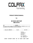
SERVICE MANUAL
®
MOYNO
™
Annihilator
Series 2
Table of Contents
1-1. INTRODUCTION ..................................................................................................................................1
1-2. GENERAL .............................................................................................................................1
1-3. NAMEPLATE DATA ..............................................................................................................1
1-4. Model Number ............................................................................................................1
1-5. Frame Designation .....................................................................................................1
1-6. Trim Code...................................................................................................................2
1-7. Equipment Description................................................................................................2
1-8. Grinder Unit ................................................................................................................2
1-9. Motor ..........................................................................................................................2
1-10. Reducer......................................................................................................................2
2-1. INSTALLATION ...................................................................................................................................2
2-2. GENERAL .............................................................................................................................2
2-3. Piping ...................................................................................................................................2
2-4. Foundation ............................................................................................................................2
2-5. Motor Controls.......................................................................................................................2
3-1. OPERATION
...................................................................................................................................3
3-2. INITIAL CHECK/START-UP..................................................................................................3
4.1. MAINTENANCE ...................................................................................................................................3
4-2. LUBRICATION ......................................................................................................................3
4-3. Motor Bearings .............................................................................................................3
4-4. Gear Reducer...............................................................................................................3
4-5. Cartridge Assembly ......................................................................................................3
4-6. DISASSEMBLY ...................................................................................................................3
4-7. Disconnect Grinder .....................................................................................................3
4-8. Cutter Cartridge Replacement ....................................................................................4
4-9. Motor Removal………………………………………………………………………………4
4-10. Gear Reducer Removal ..............................................................................................4
4-11. Cartridge Disassembly................................................................................................4
4-12. INSPECTION.......................................................................................................................4
4-13. ASSEMBLY .........................................................................................................................4
4-14. Bearing / Seal Cartridge Assembly.............................................................................5
4-15. Cartridge Assembly…………………………………………………………………………5
4-16. Reducer/Motor Assembly ...........................................................................................6
4-17. Torque Guidelines Chart ............................................................................................6
4-18. STORAGE...........................................................................................................................6
4-19. Short-Term Storage....................................................................................................6
4-20. Long-Term Storage ....................................................................................................6
4-21. Recommended Spare Parts ................................................................................................7
4-22. PARTS LIST ........................................................................................................................8
Exploded View..........................................................................................................11
MOYNO® Annihilator™
1
October 2004
Section:
Page:
Date:
SERVICE MANUAL
®
™
Moyno Annihilator
Series 2
1-1.
INTRODUCTION
The complete Annihilator unit consists of the cutter cartridge
assembly, reducer adapter, gearbox, motor, and flange
housings on in-line units (Figure 1-2).
1-2. GENERAL
The Moyno® Annihilator, twin shaft grinder, is a rugged and
reliable grinder designed to efficiently reduce the size of large
solids typically encountered in raw wastewater, primary
thickened sludge, digested sludge, slaughterhouse waste,
and pulp and paper recycling. The grinder has been tested to
assure consistent performance in the most difficult of
applications. It represents the next generation of the world’s
most reliable grinder.
The Moyno® twin Annihilator utilizes an improved version of
the counter-rotating shaft design that has proven to be a
reliable method of shredding large solids (pieces of wood,
plastic bottles, cloth towels and rags, and aluminum cans,
etc.) into smaller pieces. The slow rotating shafts are ideal
for shredding solids that are large and dense. By utilizing a
slow speed gear motor, the cutters have high torque
capability and low impact while severing debris.
The Moyno Annihilator is designed with cutting teeth on both
the cutters and spacer cutters which increases the cutting
capability of rags over other twin shaft grinders and
eliminates the greatest cause of failure – that of stringy
material wrapping around the spacers.
The Moyno Annihilator product line is modular in concept
allowing for optimal utilization of cutters for channel or in-line
units to meet the requirements of the application. The cutter
cartridge assembly allows for the removal and replacement
of the entire cutting assembly as a single unit. The cutter
cartridges consist of a top and bottom housing, side rails,
bearing/seal cartridges, hex shafts, cutters, and spacer
cutters (Figure 1-1.).
Figure 1-2. Complete unit.
1-3. NAMEPLATE DATA
The grinder nameplate, located on the top housing, contains
important information relating to the operation and servicing
of the grinder. This information includes the model and serial
numbers (see Figure 1-3.). The grinder model number must
be used for reference when ordering a replacement cartridge
or spare parts.
Model:
MFG Serial:
M12F2 CE7R7R
ASXXXXXX
Date:
10/04
Figure 1-3. Typical nameplate data
1-4. Model Number. The grinder model number consists of
two component parts: Frame Designation and a Trim Code.
A typical model number, for example, might be M12F2
CE7R7R as shown on the nameplate in Figure 1-3.
1-5. Frame Designation. The five characters in the frame
designation describe the particular combination of
construction and cutter height.
The first character in the frame designation, always a letter,
indicates the construction as either a complete unit (M) or
replacement cartridge (C).
Figure 1-1. Cutter cartridge.
Page 2
The second and third characters, always numbers, indicate
either the flange size or cutter stack height.
The fourth character is a letter indicating whether it’s a flange
unit (F) or channel unit (C). If the fourth character indicates a
flange unit, the second and third characters indicate the
flange size in inches. If the fourth character indicates a
channel unit, the second and third characters indicate the
cutter stack height.
The fifth character indicates the series of the unit:
Series 2 -- 2½” hex shaft
Series 3 – 2” hex shaft, design after July 2003
Series 4 – 2” hex shaft, one-piece flange housing design
1-6. Trim Code. Also included in the Model Number is the
six character Trim Code which is used to identify grinder
construction.
The first letter identifies the materials of construction.
C -- Cast iron, ductile iron, and alloy steel
S -- Stainless steel
X -- Special
The second letter identifies the type of drive utilized.
E -- Electric motor and gear box
S -- Submergible motor and gear box
H -- Hydraulic motor with power package
X -- Special
The third and fourth characters identify the type of cutters on
the drive shaft:
5R – 5 tooth reversible
7R – 7 tooth reversible
7C – 7 tooth cam
11C – 11 tooth cam
The fifth and sixth characters identify the type of cutters on
the idler shaft:
5R – 5 tooth reversible
7R – 7 tooth reversible
7C – 7 tooth cam
11C – 11 tooth cam
If the trim code of your grinder is other than the variations
listed above contact your nearest Moyno representative for
clarification. Do not modify your grinder with any variations
unless you have determined that it is compatible with your
application.
1-7 EQUIPMENT DESCRIPTION
1-8. Grinder Unit. The Moyno Annihilator is a motor driven,
double shaft design stacked with intermeshing cutters and
spacer cutters positioned on the shafts. The shafts are
constructed of a hexagonal, 4140 steel and counter-rotate at
43 and 26 RPM. The shafts contain intermeshing cutters and
spacer cutters.
The Moyno Annihilator Series 2 product line, consist of three
channel models with 18, 24 or 32 inch high cutting chamber,
and three flanged, in-line models: 12, 16 or 18 inch flanged.
1-9. Motor. Each Moyno Annihilator is equipped with a
motor:
•
TEFC or Explosion proof design
•
10 HP
•
•
1725 RPM, 3/60/230/460V
Baldor or Moyno choice
1-10. Reducer. Each Moyno Annihilator is equipped with a
cycloidal speed reducer:
•
40:1 ratio
•
43 RPM output
•
Sumitomo or Moyno choice
•
Model 6170Y… 10 HP
Note: See manufacturer’s service manuals for more
details.
2-1. INSTALLATION
2-2. GENERAL
Moyno Annihilators are lubricated and tested at the factory
prior to shipment and require minimum pre-start up
maintenance.
Accessibility to the grinder and adequate clearance should
be a prime consideration in any installation. Enough space
should surround the unit so that maintenance can be carried
out with ease.
2-3. Piping. For in-line flanged units, piping should generally
be the same size as the flange and supported, not applying
vertical or horizontal forces to the grinder flanges. Be sure
to mount the unit in the piping in the proper flow
direction. Check the flow direction arrow on the grinder.
2-4. FOUNDATION
Flanged units should be mounted on a concrete base. The
base should be 4-8 inches wider then the Grinder base.
Anchor bolts are not required to attach the grinder to the
concrete base.
Check the base surface with a carpenter’s level and shim
under the grinder at the places necessary to make the unit
level. Care should be exercised to ensure the grinder
flanges are mounted in line and without piping strain.
Channel units should be mounted in a suitable framework for
support.
2-5. Motor Controls. To protect the Moyno Annihilator from
potential damage, all Grinder units should be wired to a
Moyno control panel. In the event an unusually difficult
material engage the cutting chamber, the automatic controller
senses the overload and reverses the rotation of the cutters
to clear the object. The controller then returns the Grinder to
the forward direction of rotation. It is highly recommended
that this type of overload protection be provided for all
grinders to prevent damage to the unit.
Caution:
•
Cutters and spacer cutters are very sharp. Keep
personnel clear of cutting chamber.
•
Do not lift heavy equipment over the head of
personnel.
•
Electrical hazard…Be sure power is off and locked
out.
Page 3
3-1. OPERATION
3-2. INITIAL CHECK / START-UP
CHECKLIST
Before putting the grinder into operation, the following items
should be checked to ensure that each piece of equipment is
installed correctly:
• Recheck for proper line voltage connections at the
control panel and control transformer.
Check the
transformer for continuity.
• Set the programmed controller (inside the door of the
Annihilator control panel) to the number of attempts
desired to clear jams or overloads before automatic
shutdown. The programmed controller is normally set at
3 reversals when shipped from the factory.
• Energize the incoming power lines by closing the
disconnect device. The amber light [“POWER ON”]
illuminates, indicating power is available to the control
circuitry.
• Turn the Selector Switch to the “LOCAL” position.
Depress the “Start” pushbutton.
The blue light
[“GRINDER ENABLED”] will illuminate to indicate that
the control circuits are energized and the green light
[“GRINDER RUNNING”] will illuminate indicating the
drive motor should be operating.
• Check the direction of cutter rotation.
Reversible cutters denoted as 5R or 7R, can operate in
either direction of rotation. The cutters should rotate with the
teeth rotating inward, towards one another on the inlet side of
the flow. If the motor is rotating in the reverse direction,
disconnect the power to the control panel.
CAUTION: Using a volt meter double-check that the
incoming power lines L1, L2, and L3, as well as the
motor lines T1, T2, and T3 in the control panel all
indicate that the power is OFF.
Interchange any two of the motor leads in the control panel at
Terminal Blocks T1, T2, or T3.
Do not change the
connections at the contactors. Repeat Steps 3, 4, and 5,
above.
However, cam cutters denoted as 7C or 11C, can only
operate in one direction of rotation. The cutters should also
rotate with the teeth rotating inward, towards one another on
the inlet side of the flow. With cam cutters you must first
install the unit in the piping in the correct flow orientation.
Interchange motor leads if the cutter direction is wrong.
• To test the reversing function of the programmed
controller, it is not necessary to attempt to physically jam
the grinder. Simply depress the “Test” button on the
controller inside the door of the panel. Each activation of
the “Test” pushbutton will initiate a reversal of the
grinder.
Figure 3-1. Cutters rotating inward.
4-1. MAINTENANCE
Note: In this section, a number or a letter in parentheses will
follow the first reference to each grinder part ( ). These
numbers and letters are those used to identify the grinder
parts and hardware items in the section view diagram.
4-2. LUBRICATION
4-3. Motor Bearings. The motor bearings are lubricated at
the factory and will need to be re-lubricated after 12,000
hours of operation. See your motor maintenance manual for
details.
4-4. Gear Reducer. The gear reducer is filled with grease at
the factory and will require re-lubrication every 3-5 years.
See your reducer maintenance manual for details.
4-5. Cartridge Assembly. The grinder top housing is half
full of ACG-2 grease prior to shipment and is ready for
operation. The top housing contains two gears that only
need to be re-lubricated when the assembly is being
repaired. You can re-lubricate the housing via the pressure
release grease fitting (35). The pressure release grease
fitting is pre-set at 10 psi. At pressures greater than 10 psi,
the grease will be observed exiting the grease fitting via the
bypass. This feature prevents over packing the bearings with
grease and is available through Alamite.
The bottom bearing housing is sealed and gasketed and
requires no lubrication.
List of Lubricants (or Equivalents)
See Mfg
Recommendation
See Mfg
Gear Reducer
Recommendation
ACG-2 (Dubois
Top Housing
Chemical)
Motor Bearings
4-6. DISASSEMBLY
Note: The following instructions cover grinder disassembly.
4-7. Disconnect Grinder
1.
Flush the grinder (preferably with clean water) to remove
all debris from the unit.
2.
Shut off grinder.
Page 4
4-11. Cartridge Disassembly
3.
Close suction and discharge valves.
4.
Disconnect power source.
1.
Remove the socket head screws connecting the bottom
cover (5) to the bottom housing (2) and remove the
cover and gasket (3).
2.
While holding the jaw coupling on the drive shaft,
remove both castle nuts (16) and washers (15) from the
drive and idler shafts.
4-8. Cutter Cartridge Replacement
3.
Note: The following instructions cover the removal of the
motor and gear reducer as an assembly to facilitate
replacement of the grinding cartridge.
Loosen the jaw coupling (43) set screw and remove the
coupling and key from the drive shaft (7).
4.
Remove the socket head screws connecting the housing
adapter to the top housing (2). Remove the gasket (3)
and clean grease from the top housing.
5.
Remove the retaining rings (31) from both the drive
shafts (7) and idler shaft (6).
6.
Remove both gears (12, 13) and keys (30) from the
shafts.
7.
Remove the hex screws connecting the side rails (4) to
the top and bottom housings. Remove both side rails
and gaskets (37).
8.
Remove the top housing. Clean any remaining grease
from all cavities.
9.
Remove the butt screws and washers holding the
bearing / seal cartridge in the top housing. Gently press
both cartridges out of their bores and remove the two
spacers (32).
Caution: Electrical hazard…Be sure power is off
and locked out.
5.
1.
2.
Drain any fluid in grinder.
Secure the motor/reducer with a nylon sling and support
with a hoist.
Remove cap screws connecting the reducer adapter (42)
to the housing adapter (9). Remove the reducer adapter,
reducer, and motor by lifting up with the hoist. Be
careful not to allow the assembly to tip over.
3.
Loosen the jaw coupling (43) set screw and remove the
coupling half and key from the drive shaft (7).
4.
Flanged Models….M12F2, M16F2, and, M18F2
a.
b.
c.
5.
Remove the bolts and lock washers that connect the
flange housings (41) to the inlet and outlet flanges
of the pipe.
Remove the cutter cartridge / flange housing
assembly from the piping.
Remove the cap screws and lock washers
connecting the flange housings to the cutter
cartridge. Remove the gaskets (40).
Remove and replace the cutter cartridge with a new or
rebuilt
cartridge
from
an
Authorized
Moyno
Representative.
4-9. Motor Removal
The grinder may remain in line during motor removal and
replacement.
Open and tag power disconnect in the control panel.
Disconnect and tag motor leads in the motor conduit box.
Remove the bolts connecting the motor (45) to the gear
reducer (44). Some gentle prying may be necessary to
remove the motor from the reducer.
Remove the key from the motor drive shaft.
10. Remove the excluder plates (19), cutters (10), and
spacer cutters (11) from both shafts. Be careful
removing the cutters and spacer cutters because
they are very sharp.
11. Pull both shafts from the bottom housing. Remove the
excluder plates.
12. Remove the butt screws and washers holding the
bearing / seal cartridge in the bottom housing and press
the bearing / seal cartridges out of the housing.
13. Clean all parts in a suitable cleaning solvent being
careful to observe all safety precautions regarding the
use of solvent.
4-12. Inspection
1.
Inspect all parts for wear and corrosion. Replace any
parts that worn.
2.
Replace all seals, bearings, O-rings, and gaskets.
4-10. Gear Reducer Removal
1.
Remove the bolts connecting the gear reducer to the
reducer adapter (42). Pry the gear reducer off the
reducer adapter.
2.
Loosen the jaw coupling (43) set screw and remove the
coupling and key from the reducer shaft.
3.
Remove cap screws connecting the reducer adapter (42)
to the housing adapter (9).
Remove the reducer
adapter.
4-13. Assembly
The Moyno Annihilator is generally reassembled in the
reverse order of dismantling.
During the assembly process, cleanliness is important. To
avoid premature failure, bearings, and seal components must
be handled with care and kept clean.
4-14. Bearing / Seal Cartridge Assembly
The bearing / seal cartridge can be purchased from Moyno
as a complete unit with no assembly required (See the parts
list for part numbers). All the individual components that
make-up the assembly can also be purchased.
If
components are purchased separately, follow the instruction
below for assembly.
1.
2.
3.
Carefully push the rotating portion of the mechanical
seal (18), spring end first, onto the sleeve (17). Be
careful not to damage the rubber bellows as you slide it
over the step on the sleeve.
Place the stationary portion of the seal (19) on top of the
rotating face. Place the O-ring (23) in the OD of the
stationary seal portion.
Place the ball bearing (20) on top of the stationary and
push the entire assembly down on the sleeve until the
retaining ring groove can be seen.
4.
Install the retaining ring (21) on the sleeve.
O-ring (24) in the ID of the sleeve.
Install the
5.
Repeat this procedure until all four bearing / seal
cartridges have been assembled.
4-15. Cartridge Assembly
1.
Place the bottom housing (2) upside down on the work
bench and gently push two bearing / seal cartridges
(seal end first) into the bores. The ball bearing should
be facing you.
2.
Secure each cartridge with two butt screw and washers
(38, 39).
3.
Turn the bottom housing so that it rests on it’s side.
Place two excluder plates (14) into position on the top
side of the housing.
4.
Push the lower end of both the drive and idler shafts
through the holes in the bearing / seal cartridge in the
bottom housing.
Be careful not to damage the
mechanical seals.
5.
Place the flat washer and castle nut on the end of each
shaft. Tighten castle nuts approximately ¾ of the way,
leaving them loose at this point. The castle nuts are the
prevailing torque type and will have resistance the entire
way up the thread. It will be necessary to hold the shafts
while you install the nuts.
6.
7.
8.
Turn the bottom housing / shaft assembly up on the
bench. Align both shafts so that the point of the hex is
facing toward you and perpendicular to the long edge of
the bottom housing. It does not matter which side the
drive or idler shaft is on; right or left.
Note that each cutter and spacer cutter has only 1 of the
5 cutting teeth radially in line with one point of the hex ID
hole. This tooth is denoted as the Assembly Position
(AP).
The hex shaft on your left is denoted Shaft 1, and the
one on the right is Shaft 2.
Page 5
9.
Place a large (L) cutter on Shaft 1 with the AP positioned
at Point 6 on the shaft (See figure 4-1.). Place a small
(S) spacer cutter on Shaft 2 with the AP positioned at
Point 3.
3
4
3
2
2
Shaft 1
5
4
Shaft 2
1
1
6
5
6
Figure 4-1
10. Place a small (S) spacer cutter on Shaft 1 with the AP
positioned at Point 3, then place a large (L) cutter on
Shaft 2 with the AP positioned at Point 6.
Follow the pattern below until all cutters and spacer
cutters have been installed.
Cutters and spacer cutters are very sharp. Be careful
handling them.
Shaft 1
6L
3S
1L
4S
2L
5S
3L
6S
4L
1S
5L
2S
6L
3S
Shaft 2
3S
6L
4S
1L
5S
2L
6S
3L
1S
4L
2S
5L
3S
6L
Å Repeat Starts
Cutter and Spacer Stacking Arrangement
L = Large Cutter
S = Spacer Cutter
11. Place an excluder plate over the top of each shaft down
on top of the last cutter and spacer cutter.
12. Place the top housing (2) upside down on the work
bench and place the spacer (32) inside each bore.
Gently push two bearing / seal cartridges (seal end first)
into the bores. The ball bearing should be facing up
towards you.
13. Secure each cartridge with two butt screw and washers
(38, 39).
14. Gently lower the top housing down over the ends of
each shaft being careful not to damage the mechanical
seals.
15. Place a side rail gasket (37) against one side of the
bottom housing and attached the side rail (4) with two
cap screws and washers (28). Leave the screws loose
at this point.
Page 6
2.
Place the O-ring (46) in the groove in the housing
adapter and place the drive adapter (42) on the housing
adapter. Secure the drive adapter with four hex head
screws and washers. The two longer screws thread into
the top housing along the outside and the two shorter
screws thread into the housing adapter.
3.
Slide the key (29) and coupling half (43) on the reducer
shaft and secure in place with the set screw.
18. Place a key (30) in the idler shaft and slide the large OD
gear (12) down over the key. You may have to turn the
shaft slightly to get the gear teeth to line up. Install the
retaining ring (31) in its groove above the gear.
4.
Lower the gear reducer (44) onto the drive adapter
carefully aligning the coupling halves. Align the holes in
the flanges and install and tighten the six hex screws,
washers and nuts (49).
19. Carefully lay the unit down on its side. Before you
completely tighten the two castle nuts in the bottom
housing, it will be necessary to hold the drive shaft to
prevent it from turning. You can either hold the shaft by
temporarily mounting the coupling half (43) or by
carefully wedging a small piece of soft metal between
the teeth of the two gears. After you have secured the
shafts, tighten both castle nuts.
5.
Place the key in the reducer shaft and lower the motor
(45) down onto the reducer while aligning the key and
keyway. Attach the motor to the reducer with four hex
screws and washers.
16. Slide another side rail gasket between the top housing
and side rail at the top and secure with two more cap
screws. Repeat this process on the other side and
tighten all eight screws evenly.
17. Place a key (30) in the drive shaft and slide the small OD
gear (13) down over the key. Install the retaining ring
(31) in its groove above the gear.
4-17. TORQUE GUIDELINES CHART
Stainless Steel Bolts
Max
Size
Torque
NO. 10-24 22.8 in. lb.
1/4 – 20
75.2 in. lb.
5/16 – 18
132 in. lb.
3/8 – 16
236 in. lb.
1/2 – 13
517 in. lb.
20. Place the housing gasket (3) and bottom cover (5)
against the bottom housing and secure them with six
socket head cap screws (33).
21. Carefully turn the unit upright. With a hammer, tap the
two spring dowels (8) into the two counter bored holes in
the top housing.
22. Wipe a liberal amount of ACG-2 grease on and around
each gear and fill the top housing approximately half full
of grease.
Note:
Carbon Steel Bolts
Max
Size
Torque
5/16 - 18
10 ft. lb.
3-/8 - 16
21.7 ft. lb
½ - 13
43.5 ft. lb.
5/8 – 11
86 ft. lb.
¾ - 10
152 ft. lb.
Torque values are from the Industrial Fasteners
Institute and Craftsman Corp.
4-18. STORAGE
23. Press the lip seal (25) into the housing adapter (9) with
the spring side down.
24. Place the housing gasket (3) on the top housing and
carefully slide the housing adapter over the drive shaft
and down on the gasket. Secure the housing adapter
with two socket head screws, two hex head screws and
four washers. The two socket head screws go in the
middle of the housing. The two hex head screw go in
the two holes on the idler shaft side of the housing.
4-19. Short-Term Storage. Storage of 6 months or less will
not damage the grinder. However, to ensure the best
possible protection, the following is advised:
1.
Store grinder inside whenever possible or cover with
some type of protective covering.
Do not allow
moisture to collect around the unit.
2.
See OPERATION Section before startup. Be sure all
lubricants are in good condition.
25. Install the grease fitting (26) in the housing adapter.
26. For Models….M12F2, M16F2, and M18F2
1.
2.
Place the gasket (40) against one side of the
cartridge body and place a flange housing (41)
against the gasket. Secure the flange with the
screws and washer (57). Place the gasket (52) and
inspection plate (53) against the flange housing and
secure with studs, washers, and nuts (54, 56)
Repeat the above procedure on the other side with
the second flange housing.
4-20. Long-Term Storage. If grinder is to be stored for up to
three years, perform the above short-term storage
procedures plus the following:
1.
Apply rust inhibitor to all unpainted cast iron and
machined carbon steel surfaces.
2.
Store in a dry area with dust cover.
3.
Maximum temperature 120F, minimum temperature 30F.
4.
Relative humidity should not exceed 60%. Provide
desiccation for moisture control above the maximum.
5.
Vibration levels should not exceed 2 mils at 60 hertz.
4-16. Reducer / Motor Assembly
1.
Slide the key (29) and coupling half (43) down on the
drive shaft and secure in place with the set screw. The
root of the coupling teeth should be lined up with the end
of the shaft.
Page 7
4-21. Recommended Spare Parts
Your Moyno Annihilator has been designed and built to
minimize overall operating cost. All wearable parts are
replaceable. A recommended inventory of spare parts is
dependent upon the application and the importance of
continued operation.
a.
For minimal downtime, we recommend having a
replacement cartridge in your inventory.
Page 8
4-22. PARTS LIST
Table 4-1. Parts List
REF. NO.
DESCRIPTION
PART NUMBER
2
TOP HOUSING
4251417001
3
HOUSING GASKET
4230814001
4
SIDE RAIL
5
COVER PLATE
4230813001
6
IDLER SHAFT
SEE TABLE 3
7
DRIVE SHAFT
SEE TABLE 4
8
SPRING DOWEL
6160100711
9
HOUSING ADAPTER
4251409001
10
CUTTER
11
SPACER CUTTER
4230939001
12
GEAR
4230812001
13
GEAR
4230811001
14
EXCLUDER PLATE
4230805001
15
WASHER
6230070051
16
CASTLE NUT
6140320141
17
SEAL SLEEVE
4241488001
18
SHAFT SEAL
4220733001
19
SEAL INSERT
4230806001
20
BALL BEARING
6300502101
21
RETAINING RING
6011010196
23
O-RING
3207902152
24
O-RING
3207902133
25
GREASE SEAL
6030021002
26
GREASE FITTING
4220692001
SEE TABLE 2
SEE TABLE 5
30
KEY
4220735001
31
RETAINING RING
6011020175
32
SPACER
4220734001
37
SIDE RAIL GASKET
4230809001
40
FLANGE HOUSING GASKET
SEE TABLE 6
41
FLANGE HOUSING
SEE TABLE 6
42
DRIVE ADAPTER
4251753001
43
COUPLING HALVES
4241654001
4241655001
44
REDUCER
SEE NAME PLATE
45
MOTOR
SEE NAME PLATE
46
O-RING
3207902269
52
INSPECTION PLATE GASKET
SEE TABLE 6
53
INSPECTION PLATE
SEE TABLE 6
Note A: Bearing / Seal Cartridge includes items 17, 18, 19, 20, 21, and 23.
Note B: See Table 7 for gasket kits.
Page 9
Table 2 (Ref. No. 4) ⎯ Side Rail
Model
M18C2
M24C2
M32C2
M12F2, M16F2, M18F2
Part Number
4251412001
4251413001
4251414001
4251416001
Table 3 (Ref. No. 6) ⎯ Idler Shaft
Model
M18C2
M24C2, M12F2, M16F2, M18F2
M32C2
Part Number
4251418001
4251420001
4251422001
Table 4 (Ref. No. 7) ⎯ Drive Shaft
Model
M18C2
M24C2, M12F2, M16F2, M18F2
M32C2
Part Number
4251419001
4251421001
4251423001
Table 5 (Ref. No. 10) ⎯ Cutter
Style
7R, 7 Tooth Reversible
11C, 11 Tooth Cam
Part Number
4230807001
4230911001
Page 10
Table 6 ⎯ Flange Housing Arrangement
Ref. No. 41
Model
Flange Housing
12F
16F
18F
4251783001
4251399001
4251893001
Ref. No. 40
Flange Housing
Gasket
4241489001
4241489001
4241489001
Ref. No. 53
Inspection Plate
4230908001
4230803001
4230803001
Ref. No. 52
Inspection Plate
Gasket
4230909001
4230804001
4230804001
Table 7 ⎯ Gasket Kits
Model
All Channel models
M12F2
M16F2/M18F2
Part Number
KCHA40Q
K12F20Q
K16F20Q
Note C: Channel model gasket kits include items 3 and 37.
Note D: Flanged model gasket kits include items 3, 37, 40, and 52.
Note E:
Model M18C requires 38 cutters and 38 spacer cutters.
Models M24C, M12F, M16F and M18F require 52 cutters and 52 spacer cutters.
Model M32C requires 70 cutters and 70 spacer cutters.
Note F: Pre-assembled replacement cutter cartridges are available. Consult your local Moyno
Representative for details.
© 2004 by Moyno, Inc.
® Moyno is a registered trademark of Moyno, Inc.
™ Annihilator is a trademark of Moyno, Inc.
Moyno, Inc. is a Unit of Robbins & Myers, Inc.
Printed in the U.S.A.