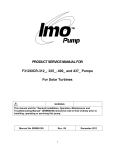
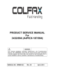
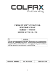
1
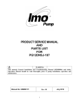
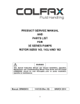
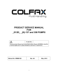
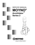
PRODUCT SERVICE MANUAL
FOR
AM322ICX-325AE, 350AN and 400A PUMPS
WARNING
This Special Instruction Manual and General Instructions Manual,
SRM00046, should be read thoroughly prior to pump installation,
operation or maintenance.
Manual No. SRM00108
Rev. 01
FEB 2015
READ THIS ENTIRE PAGE BEFORE PROCEEDING
FOR SAFETY OF PERSONNEL AND TO PREVENT DAMAGE TO EQUIPMENT, THE FOLLOWING
NOMENCLATURE HAS BEEN USED IN THIS MANUAL:
DANGER
Failure to observe precautions noted in this box can result in severe bodily
injury or loss of life.
WARNING
Failure to observe precautions noted in this box can cause injury to
personnel by accidental contact with equipment or liquids. Protection
should be provided by user to prevent accidental contact.
CAUTION
ATTENTION
Failure to observe precautions noted in this box can cause damage or
failure of equipment.
Non compliance of
safety instructions
identified by the
following symbol could
affect safety of persons:
Safety instructions
where electrical safety
is involved are
identified by:
Safety instructions
which shall be
considered for reasons
of safe operation of
pump and/or protection
of pump itself are
marked by below sign:
ATTENTION
CONTENTS
Safety and Table of Contents .......................................................................................... 1
General Instructions ........................................................................................................ 2
Introduction and Description of Equipment ..................................................................... 2
Pump Model Identification ............................................................................................... 3
Ordering instructions ....................................................................................................... 3
Operation ........................................................................................................................ 3
Parts List ......................................................................................................................... 4
Pump Disassembly ......................................................................................................... 5
Pump Assembly .............................................................................................................. 7
Installation Alignment & Troubleshooting ........................................................................ 9
Pump Assembly Drawing………………… ………………………………………………….10
ATTENTION
If operation of pump is critical to your business, we strongly
recommend you keep a spare pump or major repair kit in stock at all
times. As a minimum, a minor repair kit (o-rings and bearings)
should be kept in stock so pump refurbishment after internal
inspection can be accomplished.
1
A. GENERAL INSTRUCTIONS
Instructions found herein cover disassembly, assembly and parts identification of
AM322ICX pumps.
NOTE: Individual contracts may have specific provisions that vary from this manual.
Should any questions arise which may not be answered by these instructions,
refer to the General Instructions Manual, SRM00046, provided with your order.
For further detailed information and technical assistance please refer to Imo
Pump, Technical/Customer Service Department, at (704) 289-6511.
This manual cannot possibly cover every situation connected with installation, operation,
inspection, and maintenance of equipment supplied. Every effort was made to prepare text of
manual so engineering and design data is transformed into most easily understood wording.
Imo Pump must assume personnel assigned to operate and maintain supplied equipment and
apply this instruction manual have sufficient technical knowledge and are experienced to
apply sound safety and operational practices which may not be otherwise covered by this
manual.
In applications where equipment furnished by Imo Pump is to become part of processing
machinery, these instructions should be thoroughly reviewed to ensure proper fit of said
equipment into overall plant operational procedures.
WARNING
If installation, operation and maintenance instructions are not correctly and strictly followed
and observed, injury to personnel or serious damage to pump could result. Imo Pump
cannot accept responsibility for unsatisfactory performance or damage resulting from failure
to comply with instructions.
B. INTRODUCTION
This instruction manual covers AM322ICX pumps. These pumps have been designed for use
in turbine lubricating applications. The model, and design construction of each pump can be
identified by the designator code on pump nameplate. Definitions of model designators are
identified in Figure 1.
C. DESCRIPTION OF EQUIPMENT
The AM322ICX pumps are positive displacement, rotary screw pumps consisting of a
precision bored housing/case that encloses a driven screw (power rotor) and four
intermeshing following screws (idler rotors). These screws when rotating form a succession
of closures or cavities. As they rotate, fluid is moved axially from inlet port at center of pump
to outlet port in a continuous, uniform flow with minimum fluid pulsation and pump noise. The
/AM322ICX also has a lip seal that prevents pumped fluid from spilling out the front end.
D. PUMP MODEL IDENTIFICATION
This instruction manual covers the Imo AM322ICX pumps. Model of each pump is identified
on pump nameplate. Refer to Figure 1 for instructional keys when using this manual.
2
Model Nomenclature
AM 322 I C X - 325 AE
Lead and Rotation
Design
Modification
325 Size
AE = 1.2D, CW
400 Size
Pump
Series
A = 1.0D, CW
350 Size
AN = 1.25D, CW
Open Ball
Bearing
Power Rotor
Diameter
C-Face
Mounting
Lip Seal
Figure 1
E. ORDERING INSTRUCTIONS
When corresponding with Imo Pump regarding AM322ICX pumps, refer to pump nameplate,
this instruction manual, and assembly drawing as instructed below:
1. From pump nameplate, record pump model number, serial number & manufactured date.
2. Record instruction manual number, revision and date.
3 From assembly drawing or parts list provide the IDP number(s) and names for
replacement part(s).
4 Give above information to your Imo service representative.
Imo sales and service representatives are listed in General Instruction Manual, CA-1.
F. OPERATION
F.1 LIQUID LIMITATIONS
Never operate with thin liquids such as solvents or water. Pump is designed for liquids
having general characteristics of oil.
3
F.2 OPERATING LIMITS
CAUTION
ATTENTION
Operating conditions, such as speed, fluid viscosity, temperature inlet pressure,
discharge pressure, filtration, duty cycle, drive type, mounting, etc., are interrelated.
Due to these variable conditions, specific application limits may be different from
that of operational limitations. Equipment must not be operated without verifying
system’s operating requirements are within pump’s capabilities.
Under no circumstances are the following operating limits (specified in Table 1) to be
exceeded without specific approval from Imo Pump.
Table 1 – Normal Pump Operating and Structural Limits
MAXIMUM SPEED .......................................................................................................3000 RPM
VISCOSITY .......................................................................................................... 50 – 3000 SSU
MINIMUM – MAXIMUM LIQUID TEMPERATURE ................................. 0 to 250 F (-18 to 107°C)
MAXIMUM INLET PRESSURE ............................................................................................ 5 psig
MAXIMUM DISCHARGE PRESSURE ......................................................... 200 psig, Cont. Duty
FILTRATION .......................................................... (See General Instruction Manual, SRM00046)
DRIVE ............................................................................................................................... Direct only
MOUNTING .............................................................................................. Mounted in any attitude
G. PARTS LIST
Table 2 – Pump Parts List
IDP QTY
DESCRIPTION
KIT
IDP QTY
DESCRIPTION
1
1
Pump Case
19
1
Outboard Cover
2
1
Inboard Cover
20
1
Thrust Plate
3
12
Inboard Cover Capscrews
21
1
Name Plate
4
5
2
1
O-Rings
Balance Piston Bushing
X
22
23
1
1
Name Plate
Name Plate
6
7
8
1
2
1
Ball Bearing
Retaining Rings
Key
X
X
24
25
26
1
8
1
Name Plate
Drive Screw
Shoulder Screw
11
12
1
12
27
28
2
1
Pipe Plugs
Pin Spring
29
30
31
32
33
1
2
1
1
1
Pipe Plug
Lip Seal
Tubing / MNPT Fitting
Seal Cover O-ring
Tubing
13
14
15
16
17
18
Bearing Retainer
Thrust and Brg Retainer
Capscrews
2 Shoulder I-Bolts
4
Hex Bolts
12 Outboard Cover Hex bolts
1 Power Rotor
2 Inboard Idlers
(Set in 350 Pump Size)
2
Outboard Idlers (325 and 400
Pump Size Only)
X = Minor Repair Kit Items.
4
KIT
X
X
H. DISASSEMBLY AND ASSEMBLY INSTRUCTIONS
WARNING
Failure to observe precautions while installing, inspecting and maintaining
pump can cause injury to personnel from accidental handling of liquids that may
harm skin or clothing, or fire hazard risks from flammable liquids, or injury from
high pressure fluid jets.
DANGER
BEFORE working on equipment, make sure all power to equipment is
disconnected and locked-out.
GENERAL COMMENTS
NOTE:
Part number identifiers (IDPs) contained within parenthesis such as (10) refer to the
circled numbers shown on the assembly drawing. See Assembly and Table 2.
Tools Required
Procedures described in manual require common mechanics hand tools, a torque
wrench, dial indicator and suitable lifting device (such as) slings. They also require
fabrication of a strong-back as illustrated in figure 2 for bearing removal and a
bearing installation tool as illustrated in figure 3.
PUMP DISASSEMBLY
DANGER
Fluid Leakage from disassembly of pump may make floor slippery and can cause
personal injury.
Note: Series AM322IC pumps incorporate highly finished precision parts that must be handled
carefully to avoid damage to critical machined surfaces.
If complete overhaul of pump is required, removal of pump from its mounting and locating pump
in a suitable work area is recommended. It is also recommended that all O-rings and lip seals be
replaced during overhaul, regardless of their condition.
1. Close suction and discharge piping to pump and disconnect piping. Remove drain plug
(29), and drain unit. Remove pump from gear box or mounting bracket.
2. Remove tubing (33) and coupling half and key (8).
3. Remove hex head fasteners (15) and outboard cover (19) with o-ring (4) from case (1).
4. Remove Nylok fasteners (12) thrust plate (20) and o-ring (4) from cover (19).
5
5. Remove outboard idlers (17 or 18 on 325 and 400 sizes) by unscrewing them from their
bores.
CAUTION
ATTENTION
Do not permit idlers (17, 18) to drop as they emerge from housing (1). Be
careful not to catch fingers between idler and power rotor threads.
6. Support inboard cover (2) with a sling and overhead crane or hoist. Slowly remove inboard
cover assembly from pump case (1) after removing capscrews (12). Inboard cover
assembly includes inboard cover (2), power rotor (16), ball bearing (6), retaining rings (7),
bushing (5), retainer (11), nylok fasteners (12), seals (30), shoulder screw (26) and
inboard idlers (17).
CAUTION
ATTENTION
Be sure to grasp idlers (17) as they emerge from pump case (1) to prevent
them from falling. Be careful not to catch fingers between idler and
power rotor threads.
7. Remove o-ring (4) from inboard cover (2).
8. Remove Nylok shoulder bolt (26) and allow sleeve bushing (5) to slide out of its bore and
rest against the power rotor inboard thread face.
9. Remove Nylok fasteners (3) and bearing retainer plate (11).
10. Remove outer Truarc ring (7).
11. Remove bearing (6) as follows: (See Figure 2 below for Strongback drawing)
6
1/2" FLAT WASHER
2X 3/8" X 6" THREADED ROD
2X O 7/16
1 1/2
O 9/16
2X 3/8" HEX NUT
1/2
1/2" X 1-1/2" HEX BOLT
3
4
6
8
a. Install threaded rods 180° apart in two bearing retainer (11) holes in inboard cover (2).
b. Place ½” washer on end of power rotor (16) and then place strongback plate shown in
figure 2 over threaded rods and against washer.
c. Install a ½” bolt through strongback and tighten into threaded hole in end of power rotor
(16).
d. Install nuts on threaded rods and then thread nuts evenly to begin pressing power rotor
(16) through ball bearing (6) until power rotor is completely off bearing (6).
e. Once power rotor (16) is off bearing, remove 1/2" bolt and remove power rotor (16)
from inboard cover (2).
CAUTION
ATTENTION
Ensure the power rotor (16) does not fall to floor once it is off bearing (6).
12. Remove inner Truarc ring from power rotor.
13. Remove sleeve bushing (5) from power rotor shaft.
14. Remove ball bearing (6) from inboard cover (2) bore.
PUMP ASSEMBLY PROCEDURE NOTES
Note: Prior to assembly, all parts should be cleaned and inspected for burrs or nicks. Replace
all worn or damaged parts. Imo Pump recommends automatic replacement of O-rings and
ball bearing when parts have been removed from previously installed positions. Wipe all
parts including threaded bolts with light lubricating oil prior to assembly.
7
NYLOK FASTENER TORQUE PROCEDURE
Required torque stated on assembly drawing and supplemental torque table does not include
additional torque required to install fasteners containing Nylok inserts (pellet, strip, patch, ring,
and collar). Torque required for first application is much higher than it is for subsequent
applications. To insure that required preload on a Nylok fastened joint is achieved for each
application, following procedure is mandatory assembly practice.
1.
Using a suitable torque wrench, install fastener in mating piece until Nylock
insert is completely engaged. Note torque required.
2. Add torque measured in Step 1 to value called for on assembly drawing.
3. Complete by tightening fastener to torque value determined in 2 above.
4. This procedure must be repeated each time a Nylok fastener is reused .
Pump Assembly:
1. Slide bushing (5) into bore of inboard cover (2) aligning slot in bushing with
tapped hole in inboard cover. Install shoulder bolt (26) by tightening until
shoulder is fully seated against the face of inboard cover (2). Check to assure
that bushing (5) is not binding and is free to float.
2. Assemble ball bearing to shaft as below :
CAUTION
ATTENTION
Ball bearing (6) may be assembled to power rotor shaft by one of two methods.
When using either method, DO NOT PRESS ON BALL BEARING OUTER
RACE. Pressing on outer race for installation could damage ball bearing.
Method 1: See Figure 3 for Ball Bearing Installation Sleeve Assembly.
a. On a flat and level surface, stand power rotor on its outboard end face. Carefully lower
bushing/cover assembly from step 1. onto shaft (16). Continue to lower cover until
bushing face rests against power rotor inboard thread end face.
b. Install inner Truarc ring (7) to groove in power rotor (16).
c. Start ball bearing (6) onto power rotor (16) shaft.
d. Install 1/2” threaded rod into tapped hole in power rotor coupling end face.
e. Place sleeve on ball bearing inner race.
f. Place plate on top of sleeve with threaded rod through center hole.
g. Install flat washer and nut to threaded rod.
h. Tighten nut and begin pressing ball bearing onto shaft.
i. Install outer Truarc ring (7) once bearing is seated against inner Truarc ring (7)
8
1/2" HEXNUT
1/2" FLAT WASHER
PLATE
1/2" THREADEDROD
SLEEVE
O.D.=3.000
I.D.=2.375
1/4
7
CAUTION
ATTENTION
Use caution not to over press ball bearing beyond its desired position. Ball bearing
should just touch inner Truarc ring.
Method 2 – Oven required with temperature verification capability.
a. Place ball bearing (6) in oven and set temperature to 200°F (93°C) Maximum.
Heat ball bearing for 30 minutes.
b. On a flat and level surface, stand power rotor on its outboard end face. Carefully
lower bushing/cover assembly from step above onto shaft (16). Continue to lower
cover until bushing face rests against power rotor inboard thread end face
c. Install inner Truarc ring (7) to groove in power rotor (16).
d. Using protective gloves, remove ball bearing from oven and install onto power rotor
bearing diameter. Ball bearing should easily slide on bearing diameter and position
itself next to inner Truarc ring (7).
e. Allow ball bearing to cool, then install outer Truarc ring (7).
3. Install lip seals (30) into seal cover (11).
9
4. Raise cover assembly (2) off of power rotor end face and position ball bearing
(6) into its bore. Install bearing retainer plate (11) with previously installed lip
seals (30) using nylok fasteners (12). Torque nylok fasteners as described in
nylok torque procedure. The basic torque is 75±5 lb-in.
5. Install O-ring (4) in groove in inboard cover (2).
6. Using sling and hoist, lift assembled power rotor and cover and slide into
housing (1) power bore. Once the first threaded section (outboard end) of
power rotor is well into bore, mesh inboard idlers (17) onto inboard end of
power rotor threaded section. Continue to hold idlers in place until they are
able to be supported by their bores.
7. Install inboard cover assembly to case (1) using Nylok fasteners (3). Torque
Nylok fasteners (3) as described in the Nylok Fastener Torque procedure.
Basic torque for Nylok fastener (3) is shown on assembly drawing.
8. Install outboard idlers (17 or 18 on 325 and 400 sizes) into bores on outboard
end of case (1).
9. Install thrust plate (20) to outboard cover (19) using Nylok fasteners (12).
Torque Nylok fasteners (12) as described in Nylok Fastener Torque procedure.
Basic torque for Nylok fastener (3) is shown on assembly drawing.
10. Install O-ring (4) in groove of outboard end cover (19) and assemble outboard
end cover (19) and o-ring (4) to case (1) using hex head fasteners (15).
Torque hex head fasteners (15) to values shown on assembly drawing.
11. Install key (8) and coupling half to power rotor (16).
Installation, Alignment and Troubleshooting
For instructions regarding Installation, Alignment and Troubleshooting, See General Instruction
Manual, SRM00046.
10
Imo Pump
1710 Airport Road
PO Box 5020
Monroe, NC USA
28111.5020
T
e
l
:
+1.704.289.6511
Toll: +1.877.853.7867
Email: [email protected]
Web: colfaxcorp.com
© 2012 Colfax Fluid Handling all rights reserved.
12