1
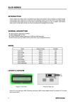
.
Berner Fachhochschule
Hochschule für Technik und
Architektur
University of Applied Sciences Berne
(Biel School of Engineering and Architecture)
The GECKO System
General Purpose Hardware/Software
Co-Design Environment for RealTime Information Processing in
System-on-Chip Solutions
Marcel Jacomet, Jörg Breitenstein, Markus Hager, William Chigutsa
MicroLab-I3S
v2.0, Mai 30, 2006
.
1.
INTRODUCTION......................................................................................................................................... 2
1.1.
1.2.
1.3.
1.4.
1.5.
1.6.
2.
GENERAL ................................................................................................................................................. 2
THE GECKO SYSTEM ................................................................................................................................ 2
SOC ......................................................................................................................................................... 2
NEW DESIGN METHODOLOGY.................................................................................................................. 3
THE GECKO DESIGN AND ANALYSIS ENVIRONMENT ............................................................................... 4
GECKO SIGNAL PROCESSING DESIGN AND ANALYSIS CONFIGURATIONS ................................................. 5
THE GECKO SYSTEM ............................................................................................................................... 9
2.1. GECKO MAIN BOARD ............................................................................................................................... 9
2.2. GECKO EXPANSION BOARDS.................................................................................................................. 11
2.2.1.
GECKO I/O Expansion Board ...................................................................................................... 12
2.3. DESIGN & ANALYSIS TOOLS, IP CORES ................................................................................................. 13
3.
GECKO TUTORIALS ............................................................................................................................... 14
3.1. TUTORIAL PREPARATION ....................................................................................................................... 14
3.1.1.
Tutorial Directory Structure ......................................................................................................... 14
3.1.2.
Tutorial GECKO Main Board Preparation .................................................................................... 15
3.2. A SIMPLE RTL DESIGN AS SOC ............................................................................................................. 15
3.2.1.
Design Description: GeckoTutorial1 ............................................................................................ 15
3.2.2.
Design Execution: GeckoTutorial1 ............................................................................................... 16
3.3. A SIMPLE MICROPROCESSOR DESIGN AS SOC ....................................................................................... 17
3.3.1.
Design Description: GeckoTutorial2 ............................................................................................ 17
3.3.2.
Design Execution: GeckoTutorial2 ............................................................................................... 18
3.4. A SIMPLE HW/SW CO-DESIGN AS SOC................................................................................................. 18
3.4.1.
Design Description: GeckoTutorial3 ............................................................................................ 18
3.4.2.
Design Execution: GeckoTutorial3 ............................................................................................... 20
3.5. ADVANCED HW/SW CO-DESIGNS AS SOC ............................................................................................ 20
4.
GECKO USER MANUAL ......................................................................................................................... 21
4.1. HOST INITIATED BOOT PROCEDURE ....................................................................................................... 21
4.1.1.
Overview ....................................................................................................................................... 21
4.1.2.
Details: Loading the USB drivers.................................................................................................. 21
4.1.3.
Details: Downloading the SoC design .......................................................................................... 23
4.1.4.
Details: SoC system start / restart................................................................................................. 25
4.2. PUSH BUTTON INITIATED BOOT PROCEDURE ......................................................................................... 26
4.2.1.
Overview ....................................................................................................................................... 26
4.2.2.
Details: Booting the SoC hardware .............................................................................................. 26
4.2.3.
Details: SoC system restart ........................................................................................................... 27
4.3. JUMPERS, SWITCHES, BUTTONS AND LEDS ............................................................................................ 28
4.3.1.
Overview ....................................................................................................................................... 28
4.3.2.
Details ........................................................................................................................................... 28
4.4. CONNECTORS ......................................................................................................................................... 30
4.4.1.
Overview ....................................................................................................................................... 30
4.4.2.
Detail: Interface connectors to host computers ............................................................................ 30
4.4.3.
Detail: Connectors to expansion boards....................................................................................... 31
4.5. INTERFACE USB TO SOC ........................................................................................................................ 32
4.5.1.
Overview ....................................................................................................................................... 32
4.5.2.
Details ........................................................................................................................................... 33
5.
APPENDICES ............................................................................................................................................. 35
5.1.
6.
SCHEMATICS TO THE GECKO MAINBOARD V2.0..................................................................................... 35
REFERENCES............................................................................................................................................ 39
MicroLab-I3S
Page 1
v2.0, Mai 30, 2006
1.
Introduction
1.1.
General
The GECKO system is a general purpose hardware/software co-design environment for real-time
information processing for system-on-chip (SoC) solutions. The GECKO system supports a new
design methodology for system-on-chips, which necessitates co-design of software, fast hardware
and dedicated real-time signal processing hardware. Within the GECKO system, the GECKO main
board represents an experimental platform, which offers the necessary computing power for speed
intensive real-time algorithms as well as the necessary flexibility for control intensive software
tasks. The fast prototyping experimental hardware platform represents a key step towards final
system-on-chip solutions by verifying the SoC implementation in the real-time environment and by
analyzing the processed data.
1.2.
The GECKO System
The GECKO system is composed of different hardware boards and software tools. The core element
of the GECKO system is the GECKO main board. In addition to the main board, an application
specific GECKO expansion board has to be added, if sensors, actuators, power elements or other
analog electronic circuitries are part of the target SoC solution. A key element of the GECKO
system is the tight link of the GECKO main board to various state-of-the-art design tools. Dedicated
drivers, IP (intellectual property) blocks and compilers are responsible to bridge the gap between
selected commercial available design and analysis tools and the GECKO main board.
1.3.
SoC
Generally speaking, a system can be described by three parts: a user, an algorithm and a plant. The
challenge of the designer is to model the interaction between the three parts, to model the plant, and
sometimes even to model the user. Once the models are verified, algorithms have to be developed
and implemented into an SoC, realizing the interaction as described. A block diagram of a general
system is shown in Figure 1. The plant may have different actuators and sensors interacting with
some sort of chemical, mechanical or other physical processes. The modelling of the plant may be
quite a complex task. The block algorithm in Figure 1 is our electronic system, able to process the
sensor and user data as well as able to control the actuators and generate the user information. This
generalized system-model will serve us throughout the present manual to describe the different
design and analysis steps.
MicroLab-I3S
Page 2
v2.0, Mai 30, 2006
Figure 1: Block diagram of a generalized system. The system is composed of three elements, the
user, the algorithm and the plant.
Today’s SoC technologies offer sophisticated potentialities. Power elements, sensors, actuators,
analog blocks and digital systems including software can be integrated on one single chip.
Sometimes, a two-chip solution is preferred due to economical reasons, separating the digital part
from the power or analog part. The GECKO system supports the two-chip approach. A large FPGA
supports fast prototyping of the digital system part, and the expansion board serves as application
specific hardware for the power, sensor or actuator part of the target system (see Figure 2).
Figure 2: Block diagram of a general SoC. The GECKO system supports the two-chip approach by
placing the digital and software subsystem on the GECKO main board and the power, sensor or
actuator elements on an application specific GECKO expansion board.
In the following text, the SoC always refers to the hardware/software (HW/SW) system the
designer is going to develop and to implement into the GECKO boards.
1.4.
New Design Methodology
In data-flow applications, e.g. digital signal processing, the behavior of the system is scheduled at a
fixed rate, and the main complexity of the design comes from the mathematical operations on data.
As long as precise models of the data to be processed are not available, as is often the case, a
straightforward design approach is impossible or at least risky. The flexibility of iteratively
improving analog/digital hardware implemented algorithms is thus necessary in order to explore
the architecture and to refine its implementation. This involves monitoring capabilities of the SoC
MicroLab-I3S
Page 3
v2.0, Mai 30, 2006
in its real-time environment. Thus an important problem in the classical ASIC hardware/software
co-design approach can be identified as the decoupling of the design steps from the prototyping
hardware in the design flow, which inhibits the necessary monitoring task in an early design phase.
The modern design flow specify-explore-refine can easily be adapted to the needs for real-time
information processing (see Figure 3). Adding an additional prototyping step and an analysis step
opens the potentiality to iteratively improve the SoC design. The refine-prototype-analysis design
loop matches best the needs of SoC designs with real-time constraints. If precise models of the data
to be processed are missing, thorough data analysis and subsequent refinement of the data
processing algorithms is a must for designing high quality SoC. To conclude, the specify-explorerefine design flow should be extended to a specify-explore-refine-prototype-analyze design flow for
SoC designs with real-time constraints as it is provided by the GECKO system (see [JGBH01]).
Figure 3. The specify-explore-refine design flow is extended to a specify-explore-refine-prototypeanalyze design flow for SoC designs with real-time constraints.
1.5.
The GECKO Design and Analysis Environment
The GECKO system uses commercially available, state-of-the-art design and analysis tools for its
real-time hardware/software design environment. This approach guaranties the user to be able to
use the most sophisticated and widely accepted tools from the designer’s community. Figure 4
illustrates the concept of the GECKO real-time information processing and development
environment for SoC solutions.
The design entry is done by the three design environments. Software programming is mainly used
for control-intensive tasks. In our case we use the C programming language, an IP core out of a set
of microprocessor hardware models, and a C compiler. General purpose, speed-intensive tasks are
preferably implemented in register-transfer-logic (RTL) hardware using a hardware description
language (HDL). Signal processing tasks with real-time constraints can be developed with the
Matlab/Simulink environment on a very comfortable high level. The separation of the three design
entry points according to their functionality provides the best possible abstraction level for the SoC
design. All three sub-designs are converted to VHDL, compiled to a net-list, and placed and routed
to the target FPGA on the GECKO main board. The tight link between the HW/SW co-design flow
MicroLab-I3S
Page 4
v2.0, Mai 30, 2006
and the general purpose main board can be seen in Figure 4. Data analysis of a running prototype is
a very important and crucial design step in our fast prototyping design methodology. Therefore, an
additional data-capture hardware block is available on the GECKO main board. Critical data can
now be captured on-line and can be analyzed by Matlab/Simulink off-line in order to iteratively
improve the algorithm design by analyzing real world data (see [JGBH01]
Figure 4: GECKO general purpose real-time HW/SW co-design environment. The SoC design can be
developed partially in C for the software tasks, in VHDL for the hardware tasks and in
Matlab/Simulink models for the signal processing algorithms. The complete design can subsequently
be compiled into an FPGA on the GECKO main board.
1.6.
GECKO Signal Processing Design and Analysis
Configurations
As shown in the previous sections, the new design methodology asks for a high flexibility in the
configuration of the design steps. Fast prototyping and data analysis design steps are necessary in
order to iteratively refine and improve the designed algorithm. The decision which part of the
system should be analyzed on the highest possible abstraction level and which part needs to be
implemented as a fast prototype in the real world strongly depends on the nature of the plant as
well as on the maturity of the signal processing algorithm itself.
Case A: Algorithms with plants that can easily be modeled are preferably be analyzed on the
highest abstraction level possible as a whole. This highest abstraction level is Matlab/Simulink.
This case represents the closed loop simulation of the system on the high abstraction modeling
level (see Figure 5).
MicroLab-I3S
Page 5
v2.0, Mai 30, 2006
Figure 5: Closed-loop configuration for simulation modeling only.
Case B: Algorithms, with plants which are difficult to model, are preferably first – at least partially
- be implemented on a high abstraction level using Matlab/Simulink, directly controlling the real
world actuators and sensors. This configuration is only possible if the actuators and sensors in the
plant are not dependent on each other and thus the sensor data can be captured off-line. This
configuration represents an open loop with real world data provided for the algorithm modeling
level. The GECKO system fully supports this case (see Figure 6).
Figure 6: Open loop configuration for algorithm implementation with real sensor data.
Case C: As described in case B, algorithms, with plants which are difficult to model, are preferably
first (partially) be implemented on a high abstraction level using Matlab/Simulink, directly
controlling the real world actuators and sensors by a hardware-in-the-simulation loop. In case the
real-time constraints are not too strict (sampling rates are not too high), this configuration can be
realized using Matlab/Simulink for the algorithmic part and the GECKO boards for controlling the
actuators and capturing the sensor data. The GECKO system fully supports this case as long as the
real-time constraints are not exceeding the Matlab/Simulink speed limitations. This case is also
called hardware-in-the-simulation loop and is subject in our current research work (see Figure 7).
MicroLab-I3S
Page 6
v2.0, Mai 30, 2006
Figure 7: Closed loop configuration for algorithm implementation with real sensor data (hardwarein-the-simulation-loop).
Case D: Once first algorithm solutions are developed on the Matlab/Simulink environment, the
algorithms can be implemented and executed as fast prototypes on the GECKO main board. With the
on-line data capture feature of the GECKO main board, critical data can be stored locally and be
analyzed off-line on the Matlab/Simulink environment for data analysis purposes and further
algorithm improvement. This configuration represents a fast prototype closed-loop system
implementation. Again the GECKO system fully supports this case (see Figure 8, see also
[JGHC02]).
Figure 8: Closed loop configuration for fast prototyping implementation.
Case E: Once first algorithm solutions are developed on the Matlab/Simulink environment, the
algorithms can be implemented and executed as fast hardware-in-the-loop prototypes on the GECKO
main board. With the on-line data capture feature of the GECKO main board, critical data can be
analyzed on-line on the Matlab/Simulink environment for data analysis purposes and further
algorithm improvement. In addition, parameters can be changed on-line in the Matlab/Simulink
environment and immediately be updated on the running hardware. This configuration represents a
fast prototype closed loop system implementation. This configuration is also called the hardwarein-the-loop system implementation. The described hardware-in-the-loop system implementation is
subject of our current research work and is currently running with limitations only.
MicroLab-I3S
Page 7
v2.0, Mai 30, 2006
Figure 9: Hardware-in-the-loop configuration for fast prototyping implementation.
MicroLab-I3S
Page 8
v2.0, Mai 30, 2006
2.
The GECKO System
2.1.
GECKO Main Board
The GECKO boards consist of two type of boards: the GECKO main board and the application
specific GECKO expansion boards. The GECKO main board is based on a large RAM-based FPGA
(Spartan II family from Xilinx Inc, XC2S100 or XC2S200 chips). The FPGA is supposed to hold
the prototype versions of the complete digital part of the system-on-chip solution. Important is the
additional on-board data capture RAM of the GECKO main board, which is used to store the sampled
data from the expansion board for the signal analysis phase. An USB interface chip (EZ-USB from
Cypress) with an on-chip 8051 microprocessor interfaces our SoC FPGA of the main board with a
host computer. Large sets of the sampled data can be uploaded through the USB interface into the
Matlab/Simulink development tools. The offer of such an off-line processing of real data is very
important in order to analyze the source data and to devise refinements for the real-time
information processing algorithms. In iterative steps the refined algorithms can again be
downloaded to the SoC FPGA. Such a closed-loop refinement and analysis of real-time information
processing systems is crucial to improve the understanding of the nature of the data to be processed
as well as the necessary algorithms.
Figure 10: Photo of the GECKO main board with a size of 8cm x 8cm.
MicroLab-I3S
Page 9
v2.0, Mai 30, 2006
Figure 11: Block diagram of the GECKO main board.
The following list describes all the components of the GECKO main board as illustrated in Figure
11.
MicroLab-I3S
•
FPGA: The Xilinx FPGA XC2S200 is a 200k logic gate FPGA used to house the
SoC target system (some systems house the smaller XC2S100 FPGA).
•
FPGA Boot EEPROM: The SoC hardware configuration file for the target FPGA
can either be directly booted (hardware boot) from this parallel EEPROM or be
downloaded by the host computer on the fly (see jumper J2 configuration)
•
USB Interface: The USB interface to the host computer is used to download the
FPGA configuration files, to download the compiled microprocessor program as
well as to download and upload data from the GECKO main board to the host
computer.
•
USB EEPROM: This serial I2C EEPROM (16k x 8 bit) houses the identification
code and parameters for the USB driver.
•
USB 8051 processor: The firmware of the USB driver on the GECKO main board is
running on its on-chip 8051 processor.
•
RS232: The RS232 interface can be used by the SoC application for
communication purposes.
•
Program ROM: The Program ROM is implemented as a RAM. This external 64k
x 16bit RAM can be used for the microprocessors application software of the SoC
if the FPGA internal RAM is too small to store the microprocessor program code.
Page 10
v2.0, Mai 30, 2006
•
Program Boot EEPROM: This 32k x 8 bit serial I2C EEPROM is used to store the
software program code for the embedded microprocessor. During the software
boot procedure it is copied to the Program ROM for the microprocessor.
•
Data Capture RAM: The 64k x 16 bit RAM can be used for the data capture
feature of the GECKO board or for in the SoC application itself.
•
Clock Generator: An on board quartz clock generator can be used to clock SoC
system. The USB block has its own and independent clock.
•
Power Supply: The USB interface delivers a 5V power supply, which is used by
the GECKO main board. The necessary 3.3V and 2.5V supply voltages are
generated on-board. The current consumption from the USB power supply is
limited as defined in the USB specifications.
•
Expansion Board Connectors: Two 64 bit connectors are used to send and
receive signals from and to the GECKO expansion boards. Six 16 bit buses BusA
to BusF can be used with some limitations. Some control signals are also routed
to the Expansion Board Connectors like the on board SoC clock signal sysclk, the
expansion board clocks extclk1 and extclk2 and the on-board reset. The on board
I2C bus signals scl and sda are also available on the Expansion Board Connectors
and can be used after the software boot process is finished. System ground and all
power supply voltages are routed to the Expansion Board Connectors as well.
•
LEDs: 4 LEDs are used for system information (power on, software boot process,
download, breakpoint), the other 4 LEDs as well as 2 of the system information
LEDs (software boot process, breakpoint) can be used freely by the SoC.
•
Push Buttons: A boot push button is used to initiate the hardware boot process.
The second push button activates a reset signal, which is freely usable by the SoC
for resetting purposes and/or software boot.
•
Jumpers and Switches: Several jumpers and SMD switches are used to define
different main board configurations, like the use of the external clocks for SoC,
FPGA configuration by host or on-board EEPROM, 5V power supply from main
board routed to expansion board.
2.1.1. Files
Pin constraints file:
groups\microlab\technologie\MicroLab-lib\IPcores\GeckoMisc\pin\GECKOpinning.ctl
Schematics of the board can be found in the appendices at the end of this document.
2.2.
GECKO Expansion Boards
Application specific analog signal processing, analog interfaces, sensors, or power drivers have to
be placed on expansion boards which can be stacked on our general purpose main board. Numerous
buses can be used to exchange data between the two boards. Important is the additional on-board
RAM of the main board, which is used to store the sampled data from the expansion board for the
signal analysis phase.
MicroLab-I3S
Page 11
v2.0, Mai 30, 2006
2.2.1. GECKO I/O Expansion Board
The idea of this board combined with the GECKO main board is to have a simple development
environment to do some exercises.
Figure 12: Photo of the I/O Expansion Board
Technical Data:
•
4 switches: Normal, inverted and debounced output.
•
2 Hex-Switches: which create directly the binary code.
•
2 LED arrays: Each with ten LEDs.
•
1 LCD 7-segment display: 4 digits (HINT: The LCD-7-seg frequency must be
32 Hz).
•
1 I2C character display
LED BAR 2
LED BAR 1
LED 1
LED 2
LED 3
LED 4
LED 5
LED 6
LED 7
LED 8
LED 9
LED 10
LED 1
LED 2
LED 3
LED 4
LED 5
LED 6
LED 7
LED 8
LED 9
LED 10
HEX-Switch 2
2
I C Display
Seg 4
Seg 3
Seg 2
Seg 1
a
a
a
a
f
g
e
d
b f
c e
dp
g
d
b f
l
c e
dp
g
d
b f
c e
dp
g
d
b
HEX-Switch 1
c
Power
Switch 4
MicroLab-I3S
Switch 3
Page 12
Switch 2
Switch 1
v2.0, Mai 30, 2006
Figure 13: Block diagram of the I/O EXPANSION Board
\groups\microlab\projekte\intern\GECKO\expansion_board\
IOExpansion Board\DokuExpansion_Board_Connectors.xls
2.3.
Design & Analysis Tools, IP Cores
Some of the GECKO design and analysis tools can easily be replaced by the users own preference,
others have a very tight link to the GECKO system and cannot be replaced without major changes.
The following tools, drivers and hardware boards are currently used within the GECKO design and
analysis environment:
•
Software Development: The C-Programming environment from the company
[CCS] Inc. is used. The tools include a C editor, C libraries and a compiler for the
PIC series microprocessors from Microchip Inc. ([Mic]).
•
Microprocessor IP Cores: Several PIC microprocessors from Microchip Inc.
have been modeled as VHDL IP cores by MicroLab-I3S. Currently the following
PICs are available:
•
MicroLab-I3S
• PIC16C5X series for limited program memory size (on-chip RAM)
• PIC16C7X series for large program memory size (external RAM)
Hardware Development: To develop digital hardware the VHDL language is
used together with the Synopsys Inc. tools for entry (SGE tool), simulation (VSS
tool) and compilation (design analyzer).
•
Signal Processing: The Matlab/Simulink tools from Mathworks Inc. ([Mat]) are
a de-facto standard for design and analysis of signal processing algorithms and
are thus used for real-time constraint driven hardware implementations of the
algorithms. Xilinx Inc offers a special Toolbox for the Matlab/Simulink
environment with signal processing blocks which can be compiled to VHDL code
using the System Generator tool from Xilinx Inc .([Xil]). The synthesis of the
generated VHDL code is currently executed by the compiler from Synplicity Inc.
([Syn]) instead of the one by Synopsys (recommended by Xilinx).
•
Back-End: The place and route tasks of the synthesized VHDL netlist is done by
the Xilinx Alliance tools.
•
Download: The Xilinx FPGA configuration file of the digital circuit as well as the
compiled C software program can be downloaded into the GECKO main board
using the GECKO User Interface provided by MicroLab-I3S.
•
Data Upload, Off-Line Analysis: With the GECKO data capture feature on the
main board any signal or sensor data can be captured on-line and be stored into a
date capture RAM on the GECKO main board. The data can be uploaded to the
Matlab/Simulink environment for an off-line analysis. As the on-line data capture
is application specific, an adaptation of the GECKO driver provided by MicroLabI3S is necessary.
•
Hardware-In-The-Loop: Currently research is done in order to include the
GECKO main board into the Real-Time-Workshop from Mathworks. This would
allow us to run signal processing models partly on Matlab/Simulink and partly on
the GECKO main board in real time. Parameter change during runtime and on-line
data analysis would open new debugging and monitoring possibilities.
Page 13
v2.0, Mai 30, 2006
3.
GECKO Tutorials
3.1.
Tutorial Preparation
3.1.1. Tutorial Directory Structure
All source files of the following tutorials are available. In addition all necessary executable files for
downloading to the GECKO main board are already generated and available for the user. Tool
dependent design or configuration files are only available for the tools used at MicroLab-I3S which
are Synopsys sge schematic editor and fc2 FPGA synthesis tools, Xilinx alliance place&route and
SystemGenerator tools, Mathworks Matlab/Simulink tools, CCS C compiler tool. It is up to the
user to manage his design tools and being able to edit the necessary tool configuration files.
Information like VHDL signal to FPGA pin mapping is in addition prepared. For each of the tutorial
designs the following directory structure is available:
Gecko/
root of GECKO relevant design and library files
tutorials/
root directory for all tutorials
GeckoTutorial1/
root directory for tutorial 1
vhdl/
VHDL source files
pin/
pin location file (for Xilinx tools)
Ccode/
C source code of embedded microprocessor program
hex/
C source compiled to hex file with machine code
bit/
Xilinx FPGA configuration bit files
mat/
Matlab/Simulink source files
tools/
ASIC design tool dependent files
xilinx/
Xilinx place & route tool files
synopsys/
Synopsys sge schematic design entry and fc2 synthesis
GeckoTutorial2/
root directory of tutorial 2
… …
IPcores/
root directory for MicroLab-I3S IP cores
PIC16C7Xseries/
root directory of Microchip PIC16C7X microprocessors
src87/
VHDL files of microprocessor IP cores
sym/
Synopsys SGE design entry schematic files of IP cores
lib/
complied IP core library for Synopsys VSS simuator
PIC16C5Xseries/
root directory of Microchip PIC16C5X microprocessors
src87/
VHDL files of microprocessor IP cores
sym/
Synopsys SGE design entry schematic files of IP cores
lib/
complied IP core library for Synopsys VSS simuator
GeckoBoot/
root directory of GECKO boot and misc IP blocks
src87/
VHDL files of IP cores
sym/
Synopsys SGE design entry schematic files of IP cores
lib/
complied IP core library for Synopsys VSS simuator
PICsoftLib/
C code libraries for GECKO specific functions
Not all designs need all 3 types of input source files for VHDL, C code or Matlab/Simulink and thus
some of the corresponding directories vhdl, Ccode or mat may be empty.
If you want to execute the tutorials on the GECKO board you just need to copy the compiled files in
the tutorial directories called bit and hex to your host account. If you want to put the source design
files through your own CAD tools and then run the tutorials on the GECKO main board, you need to
copy the above design and library files and add the necessary tool configuration files prior to
synthesize the designs.
MicroLab-I3S
Page 14
v2.0, Mai 30, 2006
3.1.2. Tutorial GECKO Main Board Preparation
In all tutorials the jumpers and switches have to verified and set as described in the Figure 14. In
addition be sure, that the on-board quartz oscillator is running somewhere between 5 MHz and 15
MHz for good results. It is not relevant which type of Xilinx FPGA is mounted on the board, but
you should know its type in order to select or generate the correct configuration file. There are
currently two versions available with the following FPGA mounted, Spartan2 XC2S100 or
XC2S200 both in a QFP208 socket.
Figure 14: Jumpers and switches setting for all tutorials (to describe an example, the Standby
switch is set in position up).
3.2.
A Simple RTL Design as SoC
3.2.1. Design Description: GeckoTutorial1
A first very simple design of a “SoC” for the FPGA, called GeckoTutorial1, running on the GECKO
main board is described. The “SoC” is a simple clock divider, used as a 4 bit binary counter
connected to 4 LEDs of the GECKO main board. The “SoC” design only consists of a digital
hardware part, not using any microprocessor (see block diagram in Figure 15).
Figure 15: Block diagram of the tutorial GeckoTutorial1 design.
The design is done by means of an RTL (register transfer logic) description based VHDL code,
which has been designed manually, simulated, compiled, placed & routed to the target FPGA
technology (XC2S100 or XC2S200 Xilinx FPGA) on the GECKO main board. As a classical chip
design flow is used, it is left to the designer to execute these steps on his own design tools. In the
following Figure 16, the necessary source and result files for this first design are illustrated.
MicroLab-I3S
Page 15
v2.0, Mai 30, 2006
Figure 16: Design source and result files of the GeckoTutorial1 example.
3.2.2. Design Execution: GeckoTutorial1
In order to execute the tutorial on the GECKO main board, the user has only to download the FPGA
configuration file GeckoTutorial1_XC2S200.bit to the GECKO main board (housing a XC2S200
QFP208 pin chip as a target FPGA). The following steps have to be done:
Figure 17: GUI of the GECKO User Interface running on the host computer.
Step 1: Connect the GECKO main board with an USB port of the host computer. The
power on LED D0 is on.
Step 2: Run the GECKO User Interface on the host computer.
Step 3: Load your “SoC” design configuration bit file GeckoTutorial1_XC2S200.bit
into the GECKO User Interface by using the Browser button in the
Programming section of the drivers GUI (see Figure 17).
MicroLab-I3S
Page 16
v2.0, Mai 30, 2006
Step 4: Download the file by using the Program button in the Programming section
of the drivers GUI. The LED D7 will be on for a fraction of a second,
signaling the hardware downloading. Quit the GECKO User Interface.
Step 5: Press the reset Push Button SW2 on the GECKO main board to start the
application correctly. Quite often the application may start without pressing
the reset Push Button, as the FPGA internal registers are always reset to logic
‘0’ values after loading the SoC design.
As the binary counter of the application is connected to the LEDs D5 downto D2, you will see the
binary output value counting up for a new value exactly every second for system clock frequency
of 13.56 MHz.
3.3.
A Simple Microprocessor Design as SoC
3.3.1. Design Description: GeckoTutorial2
A second very simple design of a “SoC” for the FPGA, called GeckoTutorial2, running on the
GECKO main board is described. The “SoC” is a microprocessor IP core of the Microchip
PIC16C5X processor series. Four bits of the PIC16C57 microprocessor internal port A (bits A0 to
A3) are configured as output signals and connected to 4 LEDs of the GECKO main board. The LEDs
are up/down counting the first seconds, and then flashing very fast for the following seconds. The
“SoC” design only consists of the PIC16C57 microprocessor hardware IP core and an embedded
software program running on the PIC placed in an FPGA internal Program ROM and not on the
FPGA external Program ROM chip of the GECKO main board (see block diagram in Figure 18).
Figure 18: Block diagram of the tutorial GeckoTutorial2 design.
The design is done by means of a simple C software program, which was designed manually,
simulated, and compiled to the target PIC16C57 microprocessor, resulting in a hex file for the
compiled microprocessor machine code. In the following Figure 19, the necessary source and result
files for this second design are illustrated.
MicroLab-I3S
Page 17
v2.0, Mai 30, 2006
Figure 19: Design source and result files of the GeckoTutorial2 example.
3.3.2. Design Execution: GeckoTutorial2
In order to execute the tutorial on the GECKO main board, again the user has only to download the
FPGA configuration file GeckoTutorial2_XC2S200.bit to the GECKO main board (housing a
XC2S200 QFP208 pin chip as a target FPGA). In order to run the tutorial design on the GECKO
main board, the same steps as in GeckoTutorial1 have to be executed.
Note that the configuration bit file contains the PIC microprocessor as well as the contents of its
internal program memory, which in our case is the compiled machine code (hex file) of the C
program. This means that if a new C code program is compiled, a complete design flow, starting
from VHDL synthesis down to place & route to the SoC target FPGA has to be performed.
3.4.
A Simple HW/SW Co-Design as SoC
3.4.1. Design Description: GeckoTutorial3
A third simple design of a “SoC” for the FPGA, called GeckoTutorial3, running on the GECKO main
board is described. This time the “SoC” is composed of a hardware block and a microprocessor IP
core modeling the Microchip PIC16C7X processor series, using an external Program ROM. In this
tutorial a pseudorandom number generator is implemented as SoC. In this third application the user
can communicate with the SoC through the GECKO User Interface running on the host computer.
The user can download commands to the SoC and upload results (SoC commands: 00 for stopping
the pseudorandom generator, 01 for running the pseudorandom generator, 02 for single
pseudorandom value reading, 03 for continuously pseudorandom values reading). The SoC
commands can be downloaded to the SoC by the byte send command of the GECKO User Interface.
The results are available at the GECKO User Interface in the byte receive window for the SoC single
reading mode or with the file open/close command for the SoC continuously reading mode. The
pseudorandom generator is implemented as a dedicated hardware block, the control logic and
communication to the USB interface are implemented in software, running on the embedded
microprocessor.
Three bits of the hardware random pattern generator are connected to 3 LEDs of the GECKO main
board, signaling to the user its operation mode (LED D5 for pseudorandom generator stopped, LED
D4 for pseudorandom pattern generator running, LED D3 for reading single or continuously random
value, on for 1 second for each reading). The PIC port E is connected to the USBdata bus for data
exchange with the USB 8051, the port D (D0 to D3) is used for the necessary handshake signals.
The PIC port B is used to interface with the hardware block generating pseudorandom values, port
A (bits A0 to A2) is used to control the communicate with the pseudorandom pattern generator
MicroLab-I3S
Page 18
v2.0, Mai 30, 2006
hardware block. The embedded software program is stored on the FPGA external Program ROM
chip of the GECKO main board (see block diagram in Figure 20).
Figure 20: Block diagram of the tutorial GeckoTutorial3 design.
The design is done by means of a hardware block, manually designed with VHDL code and a simple
C software program, which was developed, simulated, and compiled to the target PIC16C77
microprocessor, resulting in a hex file for the compiled microprocessor machine code. In the
following Figure 21, the necessary source and result files for this second design are illustrated.
Figure 21: Design source and result files of the GeckoTutorial3 example.
MicroLab-I3S
Page 19
v2.0, Mai 30, 2006
3.4.2. Design Execution: GeckoTutorial3
In order to execute the tutorial on the GECKO main board, the user first has to download the
compiled hex file of the embedded PIC processor to the on-board Program RAM
GeckoTutorial3.hex followed by the FPGA configuration file for the GECKO main board
GeckoTutorial3_XC2S200.bit (housing a XC2S200 QFP208 pin chip as a target FPGA). In order to
run the tutorial design on the GECKO main board, the following steps may be executed.
Step 1: Write the command value 01 (pseudorandom generator running) into the
byte send window of the GECK User Interface. Send the command value to
the SoC. The LED D4 will activate indicating that the pseudorandom
generator is running.
Step 2: Write the command value 02 (pseudorandom generator single reading) into
the byte send window of the GECK User Interface. Send the command value
to the SoC. A pseudorandom value will be uploaded into the byte receive
window of the GECKO User Interface. Repeat step 2 to get new
pseudorandom values. The LED D3 will be activated at each reading for a
one second, indicating that the SoC is reading a single value.
Step 3: For continuously reading pseudorandom values, a file has to be opened with
the GECKO User Interface. Then the command 03 (continuously
pseudorandom values reading) has to be downloaded to the SoC. The SoC
will generate now pseudorandom values and upload them into the open file
at the host. The LED D3 will be on indicating that the SoC is continuously
reading.
Step 4: To finish continuously reading pseudorandom values, send the command 00
(stop pseudorandom generator) to the SoC and then close the file with the
GECKO User Interface. The LED D5 will be on, indicating a stop of the
pseudorandom generator.
Note that the configuration bit file does not contain the PIC microprocessor anymore. This means
that if a new C code program is compiled, the hardware synthesis has not to be re-invoked and only
the new hex file needs to be downloaded, followed the FPGA configuration bit file.
3.5.
Advanced HW/SW Co-Designs as SoC
Additional tutorials will be developed in the near future which will use a new application specific
tutorial GECKO expansion board. The expansion board will hold elements like buttons, LCD
interface, audio in and audio out interface as well as H bridges for driving dc motors. Signal
processing applications can then be designed on the Matlab/Simulink level and downloaded to the
GECKO main board holding the tutorial GECKO expansion board.
MicroLab-I3S
Page 20
v2.0, Mai 30, 2006
4.
GECKO User Manual
4.1.
Host Initiated Boot Procedure
4.1.1. Overview
The GECKO main board is used as an experimental and development board. This asks for a highly
flexible hardware and software system. In order to free the user from the complicated configuration
steps, several automatic boot procedures are implemented. The first one, the host initiated boot
procedure, is started automatically upon connecting the USB interface of the GECKO main board to
the host computer. This host initiated boot procedure is mainly used during the development phase
of the SoC design. The following 3 phases to download a design from the host to the GECKO main
board are implemented:
•
Loading the USB drivers
•
Downloading the SoC hardware and the embedded microprocessor software
program.
•
Resetting the SoC hardware and booting the embedded microprocessor (software
booting) for system start.
The following two conditions have to be satisfied for a correct host initiated boot procedure:
•
Jumper J2 has to be in position host , switch SW3 has to be in position
(Stdby=off, M2=off, M1=on, M0=off)
•
The necessary SoC configuration and program files have to be generated.
Depending on the SoC design, an interaction of the SoC design with the boot process might be
necessary in order to find an optimal solution for the SoC. Knowing the detailed host initiated boot
procedure, the designer can even adapt the default boot procedure and thus develop an application
specific host initiated boot procedure.
4.1.2. Details: Loading the USB drivers
The previously described phase to load the USB drivers of the host computer as well as of the
GECKO main board and thus setting up the connection between host computer and GECKO main
board, is actually composed of the following sequence of 10 steps (see Figure 22):
MicroLab-I3S
Page 21
v2.0, Mai 30, 2006
Figure 22: Procedure to load the USB drivers on the host computer and the GECKO main board.
Step 1: Manual connection of the host computer to the GECKO main board by
plugging in the USB interface cable. The LED D0 will be activated to indicate
the power-on status of the GECKO main board.
Step 2: The general purpose USB driver of the host operating system (Windows
95/98/ME/2000/NT/XP) will detect the presence of a new USB device and
ask for its identity (get descriptor) which is stored in the so called USB
device descriptor.
Step 3: The USB device on the GECKO main board sends its hard coded device
descriptor (1st device descriptor), which contains information like vendor
identification (Cypress) and product identification (EZ-USB) to the host
computer.
Step 4: The host computer gets the USB device descriptor from the GECKO main
board and searches the host computer operating systems INF files for a
match. A positive identification of the USB device descriptor will be possible
with the EZUSB.INF driver configuration file from the host computer. Further
activities will now be initiated according to the EZUSB.INF file.
Step 5: The host computer will now load the boot driver EZLOADER.SYS according to
the USB device descriptor and the EZUSB.INF file information. The boot
driver downloads the application firmware for the GECKO USB 8051 device.
Step 6: After storing the firmware in its internal nonvolatile memory, the GECKO
USB 8051 device executes an internal reset, which has the same effect as
plugging in the USB cable at step 2.
Step 7: The general purpose USB driver of the host operating will again detect the
presence of a new USB device and ask for its USB device descriptor.
Step 8: The firmware of the USB device on the GECKO main board sends its new
device descriptor (2nd device descriptor), which contains information like
vendor identification (MicroLab-I3S) and product identification (GECKO
main board) to the host computer.
Step 9: The host computer gets the 2nd USB device descriptor from the GECKO main
board and searches the host computer operating systems INF files for a
match. A positive identification of the USB device descriptor will again be
possible with the EZUSB.INF driver file from the host computer. Further
activities will thus be initiated according to the EZUSB.INF file.
Step 10: The host computer will now load the default application driver EZUSB.SYS
according to the 2nd USB device descriptor and the EZUSB.INF file
information.
MicroLab-I3S
Page 22
v2.0, Mai 30, 2006
Host computer and GECKO main board are now able to communicate with each other, based on the
communication functions made available from the host computer driver EZUSB.SYS and the USB
8051 firmware on the GECKO main board.
4.1.3. Details: Downloading the SoC design
There are principally two approaches to setup the SoC design in the GECKO main board. A first
approach is to download all design relevant information from a host computer. The only
precondition for this approach is the presence and setup of a USB connection as well as the correct
setting of jumper J2 in position host. In the second approach the GECKO main board can setup itself
in a stand-alone mode, without using any USB connections. This second approach will be described
in a next sub-chapter.
The following steps describe in detail the downloading of the SoC design from the host computer
to the GECKO main board. The steps are illustrated using a data flow model of the GECKO main
board. It is the designer’s responsibility to identify possible conflicts of the download procedure
and his running SoC design.
Step 1: The Jumper J1 has to be in position off. This de-connects the system clock
from the FPGA cclk pin, which is used for configuration file loading.
Step 2: The Jumper J2 has to be in position host. This de-connects the on-board
FPGA Boot EEPROM from the FPGA and thus permits configuration file
loading for the SoC from the host (hardware boot).
Step 3: Switch SW3 has to be set to the following positions: Stdby=off, M2=off,
M1=on, M0=off. This selects the FPGA mode slave parallel for loading the
configuration file from the host.
Step 4: Run the application program GECKO User Interface on the host computer:
GECKOdriver.EXE
Step 5: A GUI will appear on the host computer, where the FPGA configuration file
and the compiled software program can be selected for downloading to the
GECKO main board.
Step 6: If the SoC design is a mixed hardware/software co-design, then the internal
microprocessor of the SoC (IP microprocessor core) needs an embedded
software program to be executed and stored in some memory on the GECKO
board. This embedded C software program for the microprocessor IP core
has to be compiled prior to downloading and is thus available in form of a
machine code (hex file) for the program memory on the GECKO main board.
Select your embedded SoC software program file and download it. A sample
embedded SoC software program is available as a compiled hex file:
GeckoExample3.hex
Step 7: The GECKO download application will now download the hex file through
the USB interface to the GECKO main board. The USB 8051 firmware
receives the hex file of the embedded software program and stores it into the
Program Boot EEPROM (32k x 8 bit) via the serial I2C interface. As the
embedded software program is stored in a nonvolatile EEPROM, it has only to
be downloaded when new versions of the embedded software have been
developed.
MicroLab-I3S
Page 23
v2.0, Mai 30, 2006
Figure 23: Downloading of the embedded software program (hex file) to the Program Boot EEPROM.
Step 8: After downloading the embedded software for the SoC, the software
program needs to be copied from the Program Boot EEPROM to the Program
ROM (which is actually a RAM) via the I2C interface. A special IP software
boot circuit has been developed for the FPGA holding the necessary hardware
to copy the program code from the Program Boot EEPROM to the Program
ROM. After the hex file downloading, the GECKO User Interface will
automatically download this IP software boot circuit (bit file) into the FPGA
(LED D7 is on during downloading, hardware boot) and start its execution.
LED D6 is on during the hex file copying procedure to its final destination
(software boot), which is the Program ROM. Previously downloaded SoC
designs will now not be available anymore and have again to be downloaded
to the FPGA.
Step 9: The FPGA configuration file (bit file) is holding the digital hardware part of
the SoC design. If the SoC design is a mixed hardware/software co-design,
then the microprocessor IP core had also to be included in the SoC design
Select your SoC design file with the GECKO User Interface. Sample tutorial
designs are available as a compiled configuration bit files:
GeckoExample1.bit to GeckoExample3.bit.
Figure 24: Software boot procedure: Transferring the embedded software program from the
Program Boot EEPROM to the software program memory (Program ROM).
Step 10: Download your SoC design (bit file) with the GECKO User Interface through
the USB interface to the GECKO main board. The USB 8051 firmware
receives the FPGA configuration bit file and sends it to the FPGA. The USB
8051 configures the FPGA by using the fast parallel configuration mode of
MicroLab-I3S
Page 24
v2.0, Mai 30, 2006
the Xilinx FPGA. During downloading LED D7 will be activated for a very
short time period.
Figure 25: Hardware boot procedure: Downloading the configuration file (bit file) to the FPGA.
4.1.4. Details: SoC system start / restart
After completion of the USB driver loading and the SoC downloading phases, finally the SoC can
start its execution.
Step 11: Pressing the Push Button SW2 will activate the reset of the SoC, the
embedded microprocessor of the SoC design will be released from its reset
state and the processor starts its normal execution. The SoC is now running.
The PIC IP cores will start their normal execution without an external
activation of the reset line as their program counter is initiated the starting
address of the software program (address = 0).
As soon as the host initiated boot procedure is terminated, the I2C bus as well as the data bus
connecting the USB 8051 to the FPGA are released and available for the SoC.
Figure 26: After completing of all downloading/booting procedures, the SoC is running. The
illustration shows a SoC with an embedded IP core using an external program memory.
MicroLab-I3S
Page 25
v2.0, Mai 30, 2006
4.2.
Push Button Initiated Boot Procedure
4.2.1. Overview
In addition to the host initiated boot procedure, a so called push button initiated boot procedure can
be used. The push button initiated boot procedure is mainly used after completion of the design, as
no program or configuration files need to be downloaded from the host to the GECKO main board.
In case the SoC application does not need any USB interface, the push button initiated boot
procedure can be implemented for the SoC design. During the push button initiated boot procedure
the GECKO main board will boot itself automatically, using the stored configuration and program
files from the two on-board boot EEPROMs.
The following phases are implemented:
•
Booting the SoC hardware at power-on-reset.
•
Loading the embedded microprocessor software program (for PIC16C7X series)
and resetting the SoC hardware for system start.
The following conditions have to be satisfied for a correct host initiated boot procedure:
•
Jumper J2 has to be in position onboard , switch SW3 has to have the position
(Stdby=off, M2=off, M1=on, M0=off).
•
One of the IP software boot blocks has to be included in the SoC design. This is
in contrast to the host initiated boot procedure, where no IP software boot block
has to be included in the SoC design.
•
The two boot files are already stored in the on-board boot EEPROMs.
•
If the USB interface is not connected, an external power supply of 5V is
necessary. In this case the Jumper J3 USBPOWER has to be set.
4.2.2. Details: Booting the SoC hardware
In order to be able to use the push button initiated boot procedure, the boot files have already to be
stored in the two on-board EEPROM (see loading the USB drivers).
Step 1: The Jumper J1 has to be in position off. This de-connects the system clock
from the FPGA cclk pin, which is used for configuration file loading.
Step 2: The Jumper J2 has to be in position onboard. This connects the on-board
FPGA EEPROM to the FPGA for loading the SoC configuration file.
Step 3: Switch SW3 has to be set to the following positions: Stdby=off, M2=off,
M1=on, M0=off. This selects the FPGA mode master serial for loading the
configuration file from the FPGA EEPROM.
Step 4: The push button initiated boot procedure starts automatically upon poweron-reset. Press the Push Button SW1 for a short time period. This will restart the configuration file loading from the FPGA Boot EEPROM into the
FPGA. During the loading procedure, LED D7 will be activated (fraction of a
second), indicating the end of load when LED D7 is de-activated again. The
SoC is now loaded into the FPGA.
Step 5: If a microprocessor IP core with an external Program ROM is used then the
software boot block included in the SoC will copy the program hex file from
the serial Program Boot EEPROM to the Program ROM. Upon completion a
reset to the SoC design is issued. It is the designer’s responsibility to add the
MicroLab-I3S
Page 26
v2.0, Mai 30, 2006
software block into his SoC design and to connect the SoC design with the
boot reset line. LED D6 is on during the software copying process.
Figure 27: Hardware boot procedure: Configuration file (bit file) is loaded from the FPGA Boot
EEPROM into the FPGA.
As soon as the push button initiated boot procedure is terminated the data bus connecting the USB
8051 to the FPGA are released and available for the SoC. LEDs D1and D3 are now de-activated.
4.2.3. Details: SoC system restart
After completion of the SoC hardware and software boot phase, the SoC can again be restarted.
Step 1: Depending of the SoC design, the Program ROM of the embedded
microprocessor is located internally of the FPGA or on the Program ROM of
the GECKO main board. Upon pressing the Push Button SW2 (SoC reset), the
IP software boot block in the SoC will read the Program Boot EEPROM
through its serial I2C bus and store the embedded software program into the
Program ROM. The sample design GeckoTutorial3 uses the on-board
Program ROM for the embedded software program. During the software
transfer procedure the LED D6 will be activated.
Figure 28: Embedded software program boot procedure: Transferring the embedded software
program from the Program Boot EEPROM to the Program ROM.
Step 2: As soon as the embedded software program boot procedure is finished, the
embedded microprocessor of the SoC design will be released from its reset
state and the processor starts its normal execution. The SoC is now running.
MicroLab-I3S
Page 27
v2.0, Mai 30, 2006
A re-start of the SoC can always be provoked by initiating the embedded
software program boot procedure through the Push Button SW2.
Figure 29: After completing of all downloading/booting procedures, the SoC is running.
As soon as the push button initiated boot procedure is terminated, the I2C bus as well as the data
bus connecting the USB 8051 to the FPGA are released and available for the SoC. The SoC is now
running and LED D7 as well as D6 are de-activated (see Figure 29).
4.3.
Jumpers, Switches, Buttons and LEDs
4.3.1. Overview
In order to keep the GECKO main board flexible, a set of jumpers and switches have to be set
correctly. Push buttons are used to initiate activities, LEDs indicate their correct termination:
•
Jumpers and switches are used for download/boot configurations.
•
Push Buttons are used to initiate boot processes.
•
LEDs are used to show download and boot activities.
4.3.2. Details
In a tabular representation all downloading and boot configuration relevant elements are explained
in detail. Jumpers and switches are used to configure the GECKO main board downloading and boot
procedures:
Name
Jumper J1
Position
off
Jumper J2
onboard (1-2)
host (2-3)
MicroLab-I3S
Jumper J3
Jumper J3
on
off
Switch SW3
M2=on, M1=off, M0=off
Page 28
Function
De-connects sysclk from cclk and thus allows the
FPGA to be loaded.
FPGA configuration will be loaded from the
GECKO on-board FPGA Boot EEPROM
FPGA configuration will be downloaded from the
host computer
GECKO board will be powered by USB.
GECKO board will be powered by expansion
boards. USB power supply is not used.
FPGA configuration will be downloaded from the
v2.0, Mai 30, 2006
M2=off, M1=on, M0=on
Switch SW3
standby=off
standby=on
host computer (slave parallel FPGA mode)
FPGA configuration will be loaded from the
GECKO on-board FPGA Boot EEPROM (master
serial FPGA mode)
normal FPGA mode
sets FPGA permanently into standby mode
The Push Buttons are used to initiate the on-board boot procedure.
Name
Push Button SW1
Position
press
Push Button SW2
press
Function
Deletes the SoC design in the FPGA. If Jumper J2
is set to position onboard, then a new SoC deign
(configuration bit file) will be loaded into the
FPGA.
Loads embedded microprocessor software from
Program Boot EEPROM into Program ROM
The LEDs are used to show power on, ongoing download and boot activities.
Name
LED D0
LED D1
Position
red
red
Activity Time
immediately
LED D2-D5
LED D6
green
green
2 sec for 8KB
LED D7
red
less than 1 sec
Function
Power on
Reserved for future use (breakpoint). D2 can
currently be used by the user (logic ‘0’ for LED
on).
Can be used by the SoC (logic ‘0’ for LED on).
Copying embedded software from Program Boot
EEPROM to Program ROM (software boot). D6 can
be used by the user if no hardware boot procedure
is used within the SoC (logic ‘0’ for LED on).
FPGA configuration in progress (hardware boot)
Figure 30: Jumpers, switches, push buttons and LED of the GECKO main board.
MicroLab-I3S
Page 29
v2.0, Mai 30, 2006
4.4.
Connectors
4.4.1. Overview
The GECKO main board is used as the digital part of a SoC system. Thus numerous connections
need to be foreseen to the GECKO expansion boards, which host the analog part or power part of the
overall SoC. Two types of connectors are present on the GECKO main board:
•
Connectors for standard interfaces to host computer: USB, RS232, Boundary
Scan (JTAG).
•
Connectors for system internal buses of the SoC to the expansion boards.
4.4.2. Detail: Interface connectors to host computers
The three interfaces to the host computers serve different purposes and can be used as follows:
•
USB 1.0: (female B type connector): The interface can be used to download SoC
configuration and program files and to initiating the boot process. Once the SoC
system is configured, the USB interface can be used by the running SoC system to
communicate with the host computer in order to exchange data and commands
(see details in the following chapters).
•
RS232: (9-pin female connector type): Once the SoC system is configured, the
RS232 interface can be used by the running SoC system to communicate with the
host computer in order to exchange data and commands (see details in the
following chapters)
•
Boundary Scan / JTAG (6 pin Xilinx connector): This interface can be used by
a host computer to download the SoC configuration file to the FPGA.
Configuration file downloading through the boundary scan interface is an
alternative to use the USB interface in case the host does not support the USB
interface.
Figure 31: Interface connectors to host computers.
MicroLab-I3S
Page 30
v2.0, Mai 30, 2006
4.4.3. Detail: Connectors to expansion boards
Two 64 pin connectors con1 and con2 on each side of the GECKO main board are used for signal
and power supply connections to the GECKO expansion boards. In the following table all pins are
described in detail.
MicroLab-I3S
Signal
Name
Connector
BusA
BusB
con1
con1
BusC
con1
BusD
BusE
BusF
con2
con2
con2
scl, sda
con2
sysclk
con2
extclk1,
extclk2
con2
reset
con2
GND
+5V
con2
con2
+3.3V
con2
+2.5V
con2
Restriction
Purpose
Also used as address bus of Data
Capture RAM. BusB is not usable if
Data Capture RAM is used.
Also used as data bus of Data Capture
RAM. BusC is not usable if Data
Capture RAM is used.
Also used as data bus of FPGA external
Program ROM. BusF is not usable if
embedded
microprocessor
uses
external Program ROM.
During download and soft boot process
the I2C bus is used. Freely available
thereafter.
Clock source is the GECKO main board
clock generator (standby turns clock
off)
Clock sources are the GECKO
expansion board clock generators
(standby turns clock off at FPGA input)
Limited current available for expansion
board if powered by USB
Limited current available for expansion
board if powered by USB
Limited current available for expansion
board if powered by USB
Page 31
connected to I/O of FPGA
connected to I/O of FPGA
connected to I/O of FPGA
connected to I/O of FPGA
connected to I/O of FPGA
connected to I/O of FPGA
I2C bus connected to USB
8051, to FPGA and serial Boot
EEPROMs
Connected to FPGA GCLK0 clk
input. Default SoC system
clock from GECKO main board.
Can be used to synchronize
expansion board with main
board.
Connected to FPGA GCLK2,
GCLK3
clk
inputs,
respectively.
Active low reset. Connected to
I/O of FPGA and reset Push
Button SW2. Used for software
boot and SoC reset.
System ground
Power supply from or to main
board (see position of J3)
Power supply generated at
main board
Power supply generated at
main board
v2.0, Mai 30, 2006
Figure 32: Expansion bus connectors.
4.5.
Interface USB to SoC
4.5.1. Overview
The USB interface can be used to download SoC configuration files and initiating the boot process.
Once the SoC system is configured, the USB interface can be used by the running SoC system to
communicate with the host computer in order to exchange data and commands. The hardware
protocol for this interface between USB 8051 and the SoC housed in the FPGA is defined by the
firmware in the USB 8051. With the current firmware the communication is realized as
follows.2scirocco &
The data to be transferred between port D of the USB 8051 and at I/O on the SoC in the FPGA (see
Annex A for detailed pin numbers). Four handshake signals are used for the communication. All
handshake signals are active low:
• wrx (write Xilinx FPGA): This is a unidirectional signal from the SoC in the
FPGA, indicating that the SoC wants to write data to the USB.
MicroLab-I3S
•
wru (write USB 8051): This is a unidirectional signal from the USB 8051,
indicating that the USB wants to write data to the SoC.
•
btrdy (byte ready): This is a bi-directional signal, which is driven by the writing
device, indicating that the data is now ready for reading.
•
ack (acknowledge): This is bi-directional signal, which is driven by the receiving
device, indicating that the data has been read.
Page 32
v2.0, Mai 30, 2006
4.5.2. Details
The hardware communication between USB 8051 and the SoC housed in the FPGA is based on the
four handshake signals wrx, wru, btrdy and ack described above. The following illustration (Figure
33) describes in detail the data transfer from the SoC in the FPGA to the USB 8051:
Figure 33: Communication protocoll for data transfer from SoC to USB 8051.
Step 1: Before the SoC device can activate its wrx signal, he has to check if not the
USB 8051 has already activated its wru signal before. The SoC activates its
wrx in the SoC and drives the btrdy signal. The USB 8051 drives the ack
signal.
Step 2: The SoC again has to check if he was the only one requesting to write data.
If not both of the devices have to deactivate their requests, release their btrdy
and ack signals. They may again try to write.
Step 3: Now the SoC can place its data on the USBbus and thereafter signalling valid
data by activating the btrdy signal.
Step 4: The USB 8051 can now read the data from the USBbus and signals its correct
operation by activating the ack signal.
Step 5: The SoC deactivates the btrdy signal and thereupon releases the USBbus.
Step 6: The USB 8051 de-activates the ack signal.
Step 7: If the SoC wants to write additional data to the USB 8051, then it repeats
steps 3 to 6.
Step 8: Else the SoC terminates the data transfer by de-activating the wrx and
releasing the btrdy signal.
Note that the signals btrdy and ack are bi-directional tri-state signals and as the signals wru and wrx
they have a pull-up resistor internal to the FPGA.
The data transfer in the other direction, from the USB 8051 to the SoC is identical as described
before, except that the roles of the SoC and the USB 8051 are exchanged and thus the signals wrx
and wru (see Figure 34).
MicroLab-I3S
Page 33
v2.0, Mai 30, 2006
Figure 34: Communication protocol for data transfer from USB 8051 to SoC.
MicroLab-I3S
Page 34
v2.0, Mai 30, 2006
.
5.
Appendices
5.1.
Schematics to the Gecko mainboard V2.0
I/O
I/O
I/O
, A1A1A9
, A8A7A6A5A4A3A2
, A1A0 GCGC
A1A1A1A1
Vr
5 4 3 2Vr
1 0 Vr
LKLK
ef
ef
ef
3GC
2GC
Ba
Ba
Ba
20I/O
20
20
20
20
20
20
19
19
19
19
19
19
18
18I/O
18I/O 18K3
18K2
I/OI/O I/OI/OnkI/OI/OI/OI/OI/OI/Onk
6 5 4 3nk
2 1 0 9 5 4 3 2 1 9 8 7
5 2
0
0
0
LEDs
R8
330R
R10
330R
D2
LED
DO
NE
R11
330R
D4
LED
LE
D1
D5
LED
LE
D2
Button
s
+3.3V
R12
330R
+3.3V
R13
330R
D6
LED
LE
D3
R14
330R
D7
LED
LE
D4
R9
330R
D8
LED
R7
330R
D3
LED
BR
EA
KP
T
LE
D5
B0
D1
LED
GND
+3.3V
Tx
Rx
B0
B1
B2
B3
B4
B5
B6
B7
B8
B9
B10
B11
B12
B13
B14
B15
3
4
5
6
7
8
9
10
14
15
16
17
18
20
21
22
23
24
27
C0
29
C1
30
C2
31
C3
33
C4
34
C5
35
C6
36
C7
37
C8
41
C9
42
C10
43
C11
44
C12
45
C13
46
C14
47
C15
48
RESET 49
+3.3V
R15
3k3
M0
M1
M2
RESET
52
50
54
I/O
I/O
I/O
I/O, Vref Bank7
I/O
I/O
I/O, Vref Bank7
I/O
I/O
I/O
I/O
I/O
I/O
I/O, Vref Bank7
I/O
I/O
I/O
I/O, IRDY
I/O, TRDY
I/O
I/O
I/O, Vref Bank6
I/O
I/O
I/O
I/O
I/O
I/O
I/O, Vref Bank6
I/O
I/O
I/O, Vref Bank6
I/O
I/O
I/O
I/O
GND
SW2
RESET
SW3
SMD Switch
1
11
19
25
32
40
51
64
72
79
85
93
103
116
124
131
137
145
158
169
177
183
190
198
1 2 3 4
GND
GND
Switche
s
1
X1A
3
STANDBY
2
74LVX00M
4
X1B
6
SYSCLK
U7
4
VccOUT
EXTCLK1
GNDINH
9
3
10
14
13,56MHz
2
1
TTL_OSCILLATOR
EXTCLK2
12
GND
GCLK2
208
197
184
170
156
144
130
117
105
92
78
65
53
39
26
12
5
4
3
2
1
44
43
42
27
26
25
24
21
20
19
18
6
RAM_A_WE
17
RAM_A_OE
41
40
39
Program
U5
ROM
A0
I/O 0
A1
A2
A3
A4
A5
A6
A7
A8
A9
A10
A11
A12
A13
A14
A15
7
8
9
10
13
14
15
16
29
30
31
32
35
36
37
38
I/O 1
I/O 2
I/O 3
I/O 4
I/O 5
I/O 6
I/O 7
I/O 8
I/O 9
I/O 10
I/O 11
I/O 12
I/O 13
I/O 14
I/O 15
F0
F1
F2
F3
F4
F5
F6
F7
F8
F9
F10
F11
F12
F13
F14
F15
CE
WE
OE
UB
LB
AS7C1026TC
GND
CCLK
FPGA
M0
M1
M2
GND
GND
GND
GND
GND
GND
GND
GND
GND
GND
GND
GND
GND
GND
GND
GND
GND
GND
GND
GND
GND
GND
GND
GND
I/O (DOUT, BUSY)
I/O (DIN, D0)
I/O
I/O
I/O, Vref Bank2
I/O
I/O
I/O, Vref Bank2
I/O (D1)
I/O (D2)
I/O
I/O
I/O
I/O
I/O, Vref Bank2
I/O (D3)
I/O
I/O
I/O, IRDY
I/O, TRDY
I/O
I/O (D4)
I/O, Vref Bank3
I/O
I/O
I/O
I/O
I/O (D5)
I/O (D6)
I/O, Vref Bank3
I/O
I/O
I/O, Vref Bank3
I/O
I/O
I/O (D7)
I/O (INIT)
SYSCLK
CCLK
155
1
2
154
153
152
151
150
149
148
147
146
142
141
140
139
138
136
135
134
133
132
129
127
126
125
123
122
121
120
119
115
114
113
112
111
110
109
108
BUSY
CON2
DATA0
E0
E1
E2
E3
E4
E5
DATA1
DATA2
E6
E7
E8
E9
E10
DATA3
E11
E12
E13
E14
E15
DATA4
LED5
LED4
LED3
LED2
LED1
DATA5
DATA6
RAM_A_WE +3.3V
RAM_A_OE
RAM_B_CS
RAM_B_WE
R21
SCL
3k3
SDA
DATA7
107
INIT
106
PROGRAM
2
159
157
207
TMS
104
DONE
B0
B1
B2
B3
B4
B5
B6
B7
B8
B9
B10
B11
B12
B13
B14
B15
5
4
3
2
1
44
43
42
27
26
25
24
21
20
19
18
RAM_B_CS6
RAM_B_WE
17
RAM_B_OE
41
40
39
GND
Data Capture
U6
7
RAM
A0
I/O 0
8
A1
A2
A3
A4
A5
A6
A7
A8
A9
A10
A11
A12
A13
A14
A15
I/O 1
I/O 2
I/O 3
I/O 4
I/O 5
I/O 6
I/O 7
I/O 8
I/O 9
I/O 10
I/O 11
I/O 12
I/O 13
I/O 14
I/O 15
9
10
13
14
15
16
29
30
31
32
35
36
37
38
CE
WE
OE
UB
LB
AS7C1026TC
J2
PROM
1 2 3
GND
TMS
TDI
TDO
TCK
GND
I/OI/OI/OI/OI/OI/OI/OI/OI/OI/OI/OI/OI/OI/OI/O
57 58 59, 60 61 62
, 63 67 68 69 70 71 73, 74 75
Vr
ef
Ba
nk
5
Vr
ef
Ba
nk
5
GCGC I/OI/O
77K1
80K0 81 82
Vr
ef
Ba
nk
5
I/OI/OI/OI/OI/OI/OI/OI/OI/OI/OI/OI/OI/O
10I/O
10I/O
10I/O
83 84, 86 87 88 89 90 94 95, 96 97 98, 99
0 1 2
Vr
Vr
Vr
ef
ef
ef
Ba
Ba
Ba
nk
nk
nk
4
4
4
TDO
TCK
FPGA
Boot
U8
EEPROM
OE/RESET
D0
13
DONE 15
PROGRAM
10
21
CE
CF
CEO
CCLK 43
XC2S100
TDI
TCK
TMS
D1
D2
D3
D4
D5
D6
D7
CLK
31
3
7
5
TDO
TDI
TCK
TMS
40
29
42
27
9
25
14
19
DATA0
DATA1
DATA2
DATA3
DATA4
DATA5
DATA6
DATA7
XC1802_VQ44
11 GCLK3
13
74LVX00M
ADADADADADADADADF8F9F1F1F7F6F5
0 1
DRDRDRDRDRDRDRDR
11 10 9 8 12 13 14 15
USSY F4F3
B_SC
CLLK
K
F2F1F0 F1F1F1F1ADADADADADADADADRA
2 3 4 5 DRDRDRDRDRDRDRDRM_
0 1 2 3 4 7 6 5 B_
OE
+3.3V
1
2
3
4
Program Boot
U11
+3.3V
8
EEPROM
A0
Vcc
7
A1
A2
Vss
WP
SCL
SDA
24LC256ISM
GND
MicroLab-I3S
C0
C1
C2
C3
C4
C5
C6
C7
C8
C9
C10
C11
C12
C13
C14
C15
INIT
PROGRAM
DONE
8
Y
B
+3.3V
74LVX00M
7
GND
X1D
ADDR0
ADDR1
ADDR2
ADDR3
ADDR4
ADDR5
ADDR6
ADDR7
ADDR8
ADDR9
ADDR10
ADDR11
ADDR12
ADDR13
ADDR14
ADDR15
J1
74LVX00M
X1C
A
+2.5V
196
186
171
143
128
118
91
76
66
38
28
13
+3.3V
5
+5V
U4
VCCo
VCCo
VCCo
VCCo
VCCo
VCCo
VCCo
VCCo
VCCo
VCCo
VCCo
VCCo
VCCo
VCCo
VCCo
VCCo
8 7 6 5
SW1
PROGRAM
WI/O
CS
RI(W
RI I/O
TE
TE(C
16 16S)
)
1 0
VCCint
VCCint
VCCint
VCCint
VCCint
VCCint
VCCint
VCCint
VCCint
VCCint
VCCint
VCCint
R17 3k3
R18 3k3
R19 3k3
R20 3k3
R16
3k3
PROGRAM
I/O
I/O
I/O
, D4D5D6D7D8D9D1
, D1D1D1
, D1D1
D0D1D2D3
Vr
0Vr1 2 3 Vr
4 5
ef
ef
ef
Ba
Ba
Ba
18
18
17
17
17
17
17
17
17
16
16
16
16
16
16I/O
16I/O
I/OI/OI/O I/OI/OI/OI/OI/OI/Onk I/OI/Onk
1 0 9 8 nk
6 5 4 3 2 8 7 6 5 4 3 2
1
1
1
Page 35
v2.0, Mai 30, 2006
6
5
SCL
SDA
GND
USB EEPROM
U1
6
1
2
3
7
SCL
CE0
CE1
CE2
WC
5
SDA
24LC128-I/SN
+3.3V
GND
R3
10k
USB Interf. / USB 8051
R4
10k
U2
BKPT
SCL
SDA
36
35
R2
SCL
SDA
24R
USB-DATA
USB+DATA
41
42
R1
USBDUSBD+
24R
+3.3V
R5
43
1k5
37
13
C4
0.1u
8
Y1 12MHz
C42
C43
15p
15p
R6
10k
GND
9
DISCON
PC0/RxD0
PC1/TxD0
PC2/INT0
PC3/INT1
PC4/T0
PC5/T1
PC6/WR
PC7/RD
CLK24
FWR
FRD
WAKEUP
RESET
XIN
XOUT
D0
D1
D2
D3
D4
D5
D6
D7
32 BREAKPT
Rx
Tx
R28 - 29 nur wenn nötig bestücken.
DONE
+3.3V
INIT
+3.3V
PROGRAM
WRITE
R28
CS
99M R29
BUSY
99M
2 USB_CLK
39 CCLK
40 STANDBY
14
15
16
17
18
19
20
21
24
25
26
27
28
29
30
31
DATA0
DATA1
DATA2
DATA3
DATA4
DATA5
DATA6
DATA7
AN 2136SC
GND
GND
MicroLab-I3S
Page 36
v2.0, Mai 30, 2006
RS232 driver
U3
RxD
Tx
7
3
+5V
2
8
RXin
TXin
RXout
TXout
Vdrv
Vcc
NC
GND
1
5
Rx
TxD
6
4
DS275
GND
Expansion Board Connector (1)
Expansion Board Connector (2)
CON1
1
3
5
7
9
11
13
15
17
19
21
23
25
27
29
31
33
35
37
39
41
43
45
47
49
51
53
55
57
59
61
63
A0
A2
A4
A6
A8
A10
A12
A14
B0
B2
B4
B6
B8
B10
B12
B14
C0
C2
C4
C6
C8
C10
C12
C14
CON2
2
4
6
8
10
12
14
16
18
20
22
24
26
28
30
32
34
36
38
40
42
44
46
48
50
52
54
56
58
60
62
64
D0
D2
D4
D6
D8
D10
D12
D14
E0
E2
E4
E6
E8
E10
E12
E14
F1
F3
F5
F7
F9
F11
F13
F15
SCL
SYSCLK
EXTCLK1
+3.3V
A1
A3
A5
A7
A9
A11
A13
A15
B1
B3
B5
B7
B9
B11
B13
B15
C1
C3
C5
C7
C9
C11
C13
C15
1
3
5
7
9
11
13
15
17
19
21
23
25
27
29
31
33
35
37
39
41
43
45
47
49
51
53
55
57
59
61
63
+5V
GND
PC/104
D1
D3
D5
D7
D9
D11
D13
D15
E1
E3
E5
E7
E9
E11
E13
E15
F0
F2
F4
F6
F8
F10
F12
F14
SDA
EXTCLK2
RESET
+2.5V
2
4
6
8
10
12
14
16
18
20
22
24
26
28
30
32
34
36
38
40
42
44
46
48
50
52
54
56
58
60
62
64
+5V
GND
PC/104
RS232 Connector
GND
JTAG Connector
USB Connector
CON5
CON3
1
2
3
4
5
6
5
9
4
8
3
7
2
6
1
CON4
TMS
TDI
TDO
TCK
+3.3V
Vin
-Data
+Data
GND
JTAG
1
2
3
4
USB_Vin
USB-DATA
USB+DATA
GND
USB
GND
MicroLab-I3S
DB9
Page 37
v2.0, Mai 30, 2006
RxD
TxD
FPGA-Stützkondensatoren
SRAM-Stützkondensatoren
+2.5V
C9
0.1u
J3
USBPOWER
C44
0.01u
C11
0.1u
C46
0.01u
C13
0.1u
C48
0.01u
C15
0.1u
C50
0.01u
C17
0.1u
C52
0.01u
C19
0.1u
+3.3V
C54
0.01u
1
2
C40
0.1u
+5V
NAND-Stützkondensatoren
+5V
GND
GND
GND
GND
GND
C41
0.1u
C78
0.1u
C79
0.1u
C77
0.1u
GND
USB_Vin
GND
C10
0.1u
C45
0.01u
C12
0.1u
C47
0.01u
C14
0.1u
C49
0.01u
C16
0.1u
C51
0.01u
C18
0.1u
C53
0.01u
C20
0.1u
GND
C55
0.01u
EEPROM-M24C... Stützkond.
GND
GND
GND
GND
GND
EEPROM-24LC... Stützkond.
GND
+3.3V
+3.3V
+3.3V
4
+3.3V
U9
LM1117MP-3.3
3
Vin
Vout
+3.3V
C21
0.1u
2
C56
0.01u
GND
C23
0.1u
GND
C58
0.01u
C25
0.1u
C60
0.01u
GND
C27
0.1u
C62
0.01u
GND
C29
0.1u
C64
0.01u
GND
C31
0.1u
GND
C66
0.01u
C33
0.1u
C68
0.01u
GND
C35
0.1u
C70
0.01u
GND
C80
0.1u
C76
0.1u
GND
GND
+ C73
10u
1
+ C72
10u
GND
Plane
+5V
C22
0.1u
C57
0.01u
C24
0.1u
C59
0.01u
C26
0.1u
C61
0.01u
C28
0.1u
C63
0.01u
C30
0.1u
C65
0.01u
C32
0.1u
C67
0.01u
C34
0.1u
C69
0.01u
C36
0.1u
C71
0.01u
USB-AN21.. Stützkond.
+3.3V
XilinxProm
+3.3V
GND
GND
GND
GND
GND
GND
GND
GND
GND
GND
GND
C7
0.1u
C8
0.1u
C38
0.1u
GND
+2.5V
4
GND
3
+ C74
10u
Vin
GND
Plane
U10
LM1117LM-ADJ
Vout
2
RS232-DS275
R26
180R
+ C75
10u
+5V
C82
0.1u
GND
GND
GND
+2.5V
1
+5V
R27
180R
GND
GND
MicroLab-I3S
Page 38
v2.0, Mai 30, 2006
C39
0.1u
C81
0.1u
.
6.
References
[JGBH01] Marcel Jacomet, Josef Goette, Jörg Breitenstein, Markus Hager, On a Development
Environment for Real-Time Information Processing in System-on-Chip Solutions, IEEE
14th Symposium on Integrated Circuits and System Design, SBCCI’01, pp 28-31, Sept.
2001, Brasilia (also published in World Multiconference on Systemics, Cybernetics and
Informatics, Volume XV: Industrial Systems, ISAS SCI’2001, July 22-25th, 2001,
Orlando).
[JGHC02] Marcel Jacomet, Josef Goette, Markus Hager, William Chigutsa, Nicolas Leuba,
Hardware-in-the-Loop Simulation by linking Matlab/Simulink with a HW/SW CoDesign Rapid-Prototyping Platform, proceedings of Designers Forum at IEEE Design
Automation and Test in Europe, DATE’2002, Paris, March 3-8th, 2002.
[CCS]
CCS
Inc.
C
Compiler
Manual
for
PIC processors,
CCP
Inc.,
http://www.ccsinfo.com
[Mic]
Microchip Inc. Technical Data Sheets on PIC16C7X and PIC 16C5X series,
[Mat]
[Syn]
[Xil]
Mathworks Inc. Matlab/Simulink Tools, http://www.mathworks.com
Synplicity Synthesis Tools, http://www.synplicity.com
Xilinx Inc. System Generator Tools, http://www.xilinx.com
http://www.microchip.com
MicroLab-I3S
Page 39
v2.0, Mai 30, 2006