1
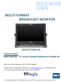
MULTI FORMAT
BROADCAST MONITOR
SERVICE MANUAL
MODEL NAME:
LVM-173W-3G 17” MULTI FORMAT BROADCAST MONITOR
KEEP THIS SERVICE MANUAL FOR FUTURE REFERENCE.
PLEASE CALL 82-70-8668-6611 OR EMAIL TO [email protected] FOR ASSISTANCES
IF YOU HAVE ANY QUESTION ABOUT LVM-173W-3G MODEL.
THIS INFORAMATION OF THIS MANUAL IS SUBJECT TO CHANGE WITHOUT ANY NOTICE.
ABOUT TVLOGIC SERVICE MANUAL:
TVLogic Service manual contains information and service procedures to
assist the service technician in understanding and correcting problem
about LVM-173W-3G model.
This information should be reviewed by a service personnel to provide a
basic understanding of how the components function in the working
system.
The troubleshooting section of this manual is intended to provide a
quick reference concerning issues that occur most frequently through
customer complaints.
We hope that technicians will repair LVM-173W-3G without any problem
through our service manual.
SERVICE PREPARATION:
A clean work area at the start of each job is essential for efficient service
work. Tools needed for the job should be ready for use before the work
is started.
2
1.SAFETY PRECAUTION
SAFETY PRECAUTIONS ABOUT DISASSEMBLY
USESET
SETVOLTAGE.
VOLTAGE.
USE
AC 100
100 ~~240V
240V (1.2A
(1.2A //50~60Hz)
50~60㎐)
--AC
- DC 12 ~ 24V (MAX 6A)
- DC 12 ~ 24V (MAX 6A)
SAFETY
PRECAUTION
ABOUT
SAFETY PRECAUTION
ABOUT
PARTS PARTS
-- Some
Some parts
partsof
ofthis
thisproduct
productshould
shouldbebehandled
handledwith
with
caution.
User
can
find
these
parts
in
a
circuit
diagram
caution. User can find those parts in a circuit diagram
and part
and
part list.
list.
Do
not
use
not recommended
recommendedby
bythe
the
- Do not use attachments
attachments not
manufacturer.
Use
of
inadequate
attachment
can
manufacturer. Use of inadequate attachment can result
in accidents.
result in accidents.
Drawing can’t be
-- Drawing
be revised
revisedwithout
withoutTVLogic’s
TVLogic’spermission.
permission.
SAFETY PRECAUTIONS ABOUT HANDING LCD MODULE
Use the
screw
holes
thecorner
corner when
when installing
the
-- Use
screw
holes
ononthe
installing
the
LCD
module.
LCD module.
-- Do
notpush
pushthe
thepanel
panel
frame
docause
not cause
an
Do not
or or
frame
and and
do not
an
electric
shocktotoprotect
protect
product
damages.
electric shock
thethe
product
fromfrom
damages.
- When handling the LCD module, put an wrist band
- When handling the LCD module, put a wrist band on to
to avoid the LCD module from static electricity
avoid static electricity with the LCD module which may
which may cause damages to the electric
cause damages to the electric components.
components.
-- Do
Do not
product
in ainhot
or humid
placeplace
for a for
notleave
leavethe
the
product
a hot
or humid
time.
along
long
time.
Keep the
away
from
direct
rays of
sunlight.
-- Keep
theLCD
LCDmodule
module
away
from
direct
rays
of the
- Sun-light.
Keep away the product from water because it’s the
reasonaway
for short
andfrom
reducing
lifebecause
span of electric
- Keep
the circuit
product
water
it’s the
components.
reason
for short circuit and reducing life span of
electric
components.
- Use
soft cloths
to wipe the surface of LCD module when
- Use
soft
cloths
to use
wipe
the surface
of LCD
module
it gets dirty. Do not
coarse
cloths which
might
cause
when
it
gets
dirty.
(Do
not
use
coarse
cloths
which
damages to the LCD module.
might cause damages to the LCD module.)
- If the product is exposed to water, you must wipe the
-If
the product is exposed to water, you must wipe
device
with with
a dry acloth
the device
to
the
device
drythen
clothdissemble
then dissemble
the
dry. to dry.
device
SAFETY PRECAUTIONS ABOUT DISASSEMBLY
- Please
cloths
or cushioned
sponge
- Please
useuse
softsoft
cloths
or cushioned
sponge when
you
when
you
disassemble
or
assemble
the
disassemble or assemble the products.
products.
- To separate the panel, release the screws on the four
- To separate the panel, release the screws
corners then slowly lift up the panel while removing
on the four corners then slowly lift up the
the panel interface cable.
panel while removing the panel interface
- Tocable.
separate the board, remove the cable from it first,
remove
the boltthe
which
is holding
downthe
thecable
board then
- To separate
board,
remove
separate.
Make
sure
the
cable
pin
is
firmly
connected
from it first, remove the bolt which is
toholding
the connector
doing it.then separate.
downwhile
the board
Make sure the cable pin is firmly connected
to the connector while doing it.
SAFETY PRECAUTIONS ABOUT ASSEMBLY
- Please
set torque
at 2K of electronic
screwASSEMBLY
driver when
SAFETY
PRECAUTIONS
ABOUT
you assemble LCD panel and cases in order to avoid
damages of screw holes on the case. This might cause
- Pleaseand
setrequire
torqueyou
at to
2Kchange
of electronic
damage
the wholescrew
case if you
driver
assemble
LCD
panel and
use
over when
torque you
of electronic
screw
driver.
cases
in order
to avoid
damages
of screw
- The
connector
should
be handled
with caution
because
it is
thin and
weak.This
Wrong
connection
malfunction
holes
of case.
might
cause causes
changing
of the board and the panel.
of whole case if you use over torque of
electronic screw driver.
WARNING
- The connector should be handled with
BE CAREFUL
OF THE ELECTRIC
SHOCK!
caution because
it is thin
and weak. Wrong
connection causes malfunction of the
board and the panel.
- Make sure to disconnect the adapter from the AC power
when replacing CCFL or inverter circuit because high
WARNING
voltage
of around 650 Vrms flows in the inverter circuit.
BEnot
CAREFUL
THE
ELECTRIC
- Do
damage theOF
cable
covers
in order to SHOCK!
avoid
accidents such as a fire and an electric shock. All the
cables
inverter
circuit must be
handled
withfrom
caution.
- Makeinsure
to disconnect
the
adapter
the AC power when replacing CCFL or
inverter circuit because high voltage about
650Vrms flows in inverter circuit.
- Do not make the cover of cables damaged
in order to avoid accidents such as a fire
3
2.CONTROLS & FUNCTIONS
4
3.FRONT KEY BUTTON
5
5
4.MONITOR DRAWING
6
5.EXPLODED DIAGRAM
7
6.1 DISASSEMBLY PROCEDURE
1) Loosen and remove 2 stand knobs on
both sides of LVM-173W-3G.
2) Release the screws. Then separate the
stand from the product.
3) Loosen and remove all the screws
around the rear and take the Rear panel
away from the product.
4) Disconnect all the cables around
the main board cover.
8
6.2 DISASSEMBLY PROCEDURE
5) Release all the screws on the main board
Cover DVI and HDMI.
7) Take the main board cover away from
the product.
6) Remove all the screws on the main
board cover.
8) Loosen and remove all the screws
attached to the main board and
dismount it.
9
6.3 DISASSEMBLY PROCEDURE
9) Remove all the screws attached to the
KP-305 and pull up the KP-305.
11) Disconnect the LVDS Cable.
10) Remove all the screws attached to the
KP-306 and pull up the KP-306.
12) Release screws on the socket bracket
and dismount it.
10
6.4 DISASSEMBLY PROCEDURE
13) Loosen and remove all the screws on
the Front and dismount the key Pad
board.
15) Separate the Front from the main
bracket.
14) Loosen and remove screws on the speaker
and dismount the speaker.
16) Remove all the screws on the side
of the panel and main bracket, then
separate them.
11
6.5 DIASSEMBLY PROCEDURE
17) Separate the tally board from the
front.
19) Front
18) Separate the tally from the front.
20) Rear
12
Other
7. DVI Functions
ANALOG/ DVI DIGITAL / HDMI RESOLUTION
DVI ANALOG/DVI DIGITAL/HDMI Support Resolution(LVM-173W-3G)
• DVI-ANALOG mode supports the following modes :
Resolution
Frequency
640 × 480
60Hz, 75Hz
720 x 400
70Hz
800 × 600
60Hz, 72Hz, 75Hz
1024 × 768
60Hz, 70Hz, 75Hz
1366 x 768
60Hz/75Hz
• DVI DIGITAL/HDMI Graphic mode supports the following modes
Resolution
Frequency
640 × 480
60Hz, 75Hz
800 × 600
60Hz, 72Hz, 75Hz
1024 × 768
60Hz, 70Hz, 75Hz
1366 x 768
60Hz/75Hz
• DVI DIGITAL/HDMI Video mode support the following input signals :
SMPTE-274M
1080i (60 / 59.94)
SMPTE-296M
720p (60 / 59.94)
SMPTE-125M
480i (59.94), 480p(59.94)
• DVI DIGITAL mode is separated into Graphic mode and Video mode.
• In DVI ANALOG/DIGITAL mode, ZERO scan must be selected for normal function.
• If the input image is in non-wide mode, press ASPECT button to change to wide display.
13
8.PRODUCT SPECIFICATIONS
LVM-173W-3G
Input
Output
Input Signal
Analog Input Spec
1 x DVI-I
DVI-I(RGB) IN
3 x BNC
Analog Input
2 x BNC
SDI A/B Channel Input
1 x HDMI
HDMI Input
3 x BNC
Analog Output
2 x BNC
SDI A/B Channel (Loop Through Out)
Analog
Composite / S-Video / Component / RGB
HD-SDI
1.485Gbps
SD-SDI
270Mbps
DVI
VESA/IBM Modes
HDMI
480i/480p/720p/1080i & VESA/IBM Modes
Composite
1.0Vpp (With Sync)
S-Video
1.0Vpp (Y With Sync), 0.286Vpp(C)
Component
1.0Vpp (Y With Sync), 0.7Vpp (Pb,Pr)
RGB
1.0Vpp (G With Sync), 0.7Vpp (B,R)
SMPTE-425M-A/B
1080p (60/59.94/50/30/29.97/25/24/23.98/30sF/29.97sF/25sF/24sF/23.98sF)
1080i (60/59.94/50)
Dual HD-SDI YPbPr (4:2:2)
SMPTE-372M
SDI Input Signal Formats
SMPTE-274M
Dual HD-SDI YPbPr/RGB (4:4:4)
1080p (50 / 59.94 / 60)
1080i (50 / 59.94 / 60)
1080p/psf (30 / 29.97 / 25 / 24 / 23.98)
1080i (60/59.94/50)
1080p (30/29.97/25/24/24sF/23.98/23.98sF)
SMPTE-296M
720p (60/59.94/50)
SMPTE-260M
1035i (60/59.94)
SMPTE-125M
480i (59.94)
ITU-R BT.656
576i (50)
2K Format
2048 x 1080(23.98p/psf, 24p/psf)
Audio In
Embedded Audio / Analog Stereo (Phone Jack)
Audio Out
Analog Stereo (Phone Jack). Internal Speaker(Stereo)
LCD
Size
16.84”
Resolution
1366 x 768 (16:9)
Pixel Pitch
0.273(H) x 0.273(W) mm
Color
16.7M(true 8bit)
Viewing Angle
H : 178 degrees / V : 178 degrees
Luminance of white
350 cd/㎡(Center)
Contrast
900:1
Display Area
372.9(H) x 209.6(V) mm
Power
DC 12V/24V/AC100~240V(1.8A/50~60Hz)
Power Consumption (Approx.)
60 Watts(Max)
Operating Temperature
0°C to 40°C (32°F to 104°F)
Storage Temperature
-20°C to 60°C (- 4°F to 140°F)
Main Body Dimensions (mm/inch)
427 x 310 x 90.5 (16.8 x 12.2 x 3.5)
Main Body Dimensions (With Stand)
474 x 327 x 150 (18.6 x 12.8 x 5.9)
Weight
7.1Kg / 15.65 lb
Accessory
AC Power cord, Manual
Option
Carrying case, V-Mount, Hood, 19” Rack Mountable Kit(7U), ND Filter, Sun-Hood
* Above specifications may be changed without notice
14
9. PCB BLOCK DIAGRAM
15
10. CIRCUIT OPERATION
<GPI Remote>
- The location of each pin is shown on the right picture.
- The selectable functions are as follows
Menu Classification
PIN 1~6
Settable Values
NONE, ANALOG CHANNEL, DIGITAL A CHANNEL, DIGITAL B CHANNEL,
PBP CHANNEL, TALLY R, TALLY G, TALLY Y, UNDER SCAN, 1:1 SCAN,
ASPECT, H/V DELAY, BLUE ONLY, MONO, 16:9 MARKER, 4:3 MARKER,
4:3 ON AIR MARKER, 15:9 MARKER, 14:9 MARKER, 13:9 MARKER,
1.85:1 MARKER, 2.35:1 MARKER, 1.85:1&4:3 MARKER, CENTER MARKER,
SAFETY AREA 80%, SAFETY AREA 85%, SAFETY AREA 88%,
SAFETY AREA 90%, SAFETY AREA 93%, SAFETY AREA 100%, 708,
608(LINE 21), 608(ANC), DYNAMIC-UMD
<LVM-173W-3G>
- PIN 7 is POWER ON/OFF use only, PIN 8 is GND.
< Video Input >
- Video input connection method
Connector
Composite
Component
S-Video
1
CVBS 1
Y
G
Y
2
CVBS 2
Pb
B
No Con.
3
CVBS 3
Pr
R
C
16
11. PROGRAM UPDATE – WEBHARD
TVLOGIC WEBHARD INFORMATION
If you need to upgrade to a new firmware with TVLogic monitors,
please visit the TVLogic webhard at h p://tvlogic.webhard.co.kr/english
ID: dealer
Password: XXXXXXXXX
Please request the password from TVLogic overseas sales team.
the password may be changed without any n
e.
17
12.1 PROGRAM UPDATE WITH ETHERNET
1) Monitor Settings
- In the OSD Menu -> REMOTE -> Enter IP Address, Subnet Mask, Gateway value.
* Changing the PORT NO. is not recommended.
* Enter the IP Address of the connected internet with monitor.
* PASSWORD feature is available with Ver. 1.0 and above.
- Leave the monitor on.
2) Upgrade program settings
- Run XVM_COMM.exe
Picture 1 : Monitor upgrade SW=>
- Enter the same IP address as entered for the monitor. (See Picture 2)
* Changing the PORT NO. is not recommended.
- When the “CON TEST“ button is pressed, Version number will appear in the
Ver. Box if connected properly. If not, “??” will appear in the box.
- If “??” appears, check the IP address for the monitor and program, then
try again.
18
12.2 PROGRAM UPDATE WITH ETHERNET
3) Firmware update
- FPGA
Picture 2 : Update setting
* Select FPGA #1 for DEV in UPDATE PROCESS. Then, OPEN and select
the FPGA firmware file.
* Press the SEND button to start transferring the firmware file to the
Ethernet Board.
Picture 3: Transfer finished message window
* Once the transfer finishes, message window appears to confirm the
start of update.
19
12.3 PROGRAM UPDATE WITH ETHERNET
Picture 4: Update start message window =>
* Press the “OK” button to start updating.
Picture 5: CONFIG SUCCESS message window =>
* “CONFIG SUCCESS” message window appears when update is finished.
- CPU
* Select ARM/GEN for DEV in UPDATE PROCESS. Then, OPEN and select
the ARM/GEN firmware file.
* Press the SEND button to start transfer.
* Follow the above FPGA updating steps to finish the update.
- VXP
* Select VXP #1 for DEV in UPDATE PROCESS. Then, OPEN and select
the VXP firmware file.
* Press the SEND button to start transfer.
* Follow the above FPGA updating steps to finish the update.
20
12.4 PROGRAM UPDATE WITH ETHERNET BOARD
4) How to Upgrade ETHERNET BOARD
Picture 6: ETHERNET BOARD Upgrade SW
- Connect the serial port of the PC and the RS232 port of monitor with a cable.
The PC must have RS232 port and cannot use the USB for RS232 converter.
See Picture 7 for the cable connection.
- Select COM PORT.
- Select “14.7456 MHz” for TARGET CLK.
- Select “2148B” for MCU TYPE.
- OPEN and select the “*.mot” file.
- Press the SEND button.
21
12.5 PROGRAM UPDATE WITH ETHERNET BOARD
MONITOR
RS232
MALE
2 : RX
2 : RX
3 : TX
3 : TX
4 : DTR
4 : DTR
5 : GND
5 : GND
6 : DSR
6 : DSR
7 : RTS
7 : RTS
8 : CTS
8 : CTS
9 : RI
9 : RI
PC
RS232
MALE
Picture 7: Cable connection for ETHERNET BOARD upgrade
22
13.1 PROGRAM UPDATE WITH USB
1) Install the CyUSB driver on your PC.
2) Turn on the monitor after connecting the PC with monitor by USB Cable.
3) Upgrade program settings
- Run LCD_PROG.exe
- Check the connection in PROGRAMMER STAUS.
23
13.2 PROGRAM UPDATE WITH USB
CAUTION:
FPGA A, CPU and VXP should be separately updated.
4) Firmware update
-FPGA
Picture 1: FPGA setting
Selectthe
FPGA
type
form
check
in PROGRAM
STATUS.
**Select
FPGA
type
check
boxbox
in PROGRAM
STATUS.
*
Select
Bank0
from
bank
selection
window.
Then
on file
* Select Bank0 from bank selection window. Then clickclick
on the
Fileopen
Openbutton
buttontotoopen
open
firmware
file
for
FPGA.
firmware file for FPGA.
**Click
DOWNLOAD
button
start
download.
Clickononthe
DOWNLOAD
button
to to
start
download.
24
13.3 PROGRAM UPDATE WITH USB
Picture 2: Download complete message window
* Update will be proceeded after Download complete. Update status appears in
SIZE/MSG
-CPU/GEN
-CPU/GEN
* Select CPU/GEN type from check box in PROGRAM STATUS.
* Select the CPU/GEN check box in PROGRAM STATUS.
* Select
Bank0
selection
window.
onFile
fileOpen
open button
button to
to open
open
* Select
Bank0
fromfrom
bankbank
selection
window.
ThenThen
click click
on the
firmware
fileCPU/GEN.
for CPU/GEN.
firmware
file for
* Click
on the
DOWNLOAD button
buttonto
tostart
startdownload.
download.
* Click
on DOWNLOAD
(Follow
the FPGA
updating
stepssteps
to finish
the update.)
(Follow
the FPGA
updating
to finish
the update.)
-VXP
-VXP
* Select
from
check
in PROGRAM
STATUS.
* Select
VXPVXP
typetype
from
check
box box
in PROGRAM
STATUS.
* Select
BANK0
from
bank
selection
window.
ThenThen
clickclick
on the
button to
to open
open
* Select
BANK0
from
bank
selection
window.
on File
file Open
open button
firmware
for VXP
firmware
for VXP
* Click on the DOWNLOAD button to start download.
* Clickthe
on FPGA
DOWNLOAD
button
(Follow
updating
steps to
to start
finishdownload.
the update).
(Follow the FPGA updating steps to finish the update.)
Selection
UPDATE
BANK0(extension)
FPGA_A(.bit)
CPU/GEN(.a79)
VXP(.bin)
BANK1(extension)
X
X
X
*** FPGA A, CPU and VXP should be separately updated. ***
25
14.1 CABLIBRATION S/W INSTALLATION
Please read the following calibration instruction before
starting calibration software with Monitors.
▪ Avoid shocks or vibrations when calibrating TVLogic monitors.
These may damage the unit and cause it to malfunction.
▪ Wait minimum 20 minutes before starting calibration with
TV Logic monitor.
▪ Start calibration when the brightness change of the screen is less
than 1cd/m².
▪ Recommendable Room temperature for calibrating monitor is
20°C ± 5°C.
▪ Recommendable Room (Environmental) brightness is less than
5 cd/m². While calibrating Monitor, light from outside should be
cut off.
▪ Do not expose this monitor directly to sunlinght while calibrating
TVLogic monitors.
26
14.2 CABLIBRATION S/W INSTALLATION
1. INSTALLATION
The calibration software requires these minimum hardware specifications:
CPU
Pentium PC
System
Windows 98SE/2000/ME/XP/VISTA/7
Display
Any compatible 24 bit video card
Designed for windows 98/2000/XP that supports
the 1024 x 768 resolution
Step 1 TVLogic Calibration Program Installation
1.1 Launch “CalibratorSetup.exe”
1.2 The “Calibration program setup window” will launch as shown below
Please click the “Next” button.
27
14.3 CABLIBRATION S/W INSTALLATION
1.3 Designate the location where the program will be installed in your PC,
and click the “Next” button.
1.4 If the user sees the image below, the installation was successful.
1.5 Please copy “LicenseKey.tvl” file into the \bin folder (found under the Calibration
program directory)
28
14.4 CABLIBRATION S/W INSTALLATION
2. CALIBRATION
The purpose of our calibration tool is to optimize the colors of LCD displays by
compensating factors which affect the LCD panel. This calibration program is
used for all of our LCD monitors. For a detailed calibration procedure, please
refer to the following.
CALIBRATION PROCEDURE
PGM Port (15 Pin Port)
Please connect the 15 pin serial cable to monitor’s factory PGM port to
your PC’s serial port.
RS-232
USB & Serial
Fig 1: Connecting to the serial port
RS-232 Port (9 Pin Port)
Connect the monitor’s factory RS232 port (PGM port) to the PC’s serial
port with the 9 pin serial cable.
Please do not connect the serial cable to the monitor directly. Use an
additional cable or connector
RS - 232 port support model: 9 pin to 9 pin connector (TX,RX,GND only)
PGM port support model: 15 pin to 9 pin connector
29
14.5 CABLIBRATION S/W INSTALLATION
If you are connecting an X-Rite, CA-210, CS-200, or an Eye-One, connect the probe with the
PC through the USB port.
Those probes which connect with USB should install the device driver offered by the
measurement device company.
(The XVM-245W supports the Klein K-10, Konica-Minolta CA-210, CS-200 and X-Rite i1
Display3 probes)
Put the measurement device facing toward the center of the monitor.
Set the input source of the monitor as SDI-A.
FCM Series, LHM Series: After input the DVI input signal, set the input source of the monitor
as DVI
If you pre-heat (or turn on) the monitor for more than 30 minutes before the calibration,
you can get a more accurate result.
30
14.6 CABLIBRATION S/W INSTALLATION
CALIBRATION PROCEDURE
1. Launch the calibration program. The main window appears as below.
Fig 2 Calibration main window
2. The probe and the monitor’s ports will be displayed on the top of the screen.
If see the port’s sign highlighted in green, it the monitor and the probe is
well connected. If it is not, the port’s sign will be highlighted in red.
Fig 3 Status of connected serial port
31
14.7 CABLIBRATION S/W INSTALLATION
3.
3. Our
Our calibration
calibration software
softwaresupports
supportsthe
theautomatic
automaticdetection
detectingofofthe
theapplied
appliedmodel
model
connected
connectedfor
formost
mostof
ofour
ourmonitors.
monitors.
However,
However, monitors
monitors using
usingthe
theGenesis
Genesisscaler
scaler(LVM-071W,
(LVM-071W, LVM-091W,
LVM-091W, LVM-XX2W,
LVM-XX2W, FCM
FCM
and
notafford
support
In In
this
case,
youyou
must
choose
the the
applied
and LHM
LHM series)
series)does
cannot
thisfeature.
feature.
this
case,
must
choose
applied
model
model manually.
manually. Afterwards,
Afterwards,click
clickthe
the“Re-Connect”
“Re
-Connect”button
buttonfor
forre-connection.
re-connection.
4.
and
make
sure
that
thethe
“Measuring
4. IfIf the
the measuring
measuringdevice
deviceisisnot
notdetected,
detected,check
check
and
make
sure
that
“Measuring
Device”
selection
under
the
Setting
menu
is
selected
correctly.
Device” selection under the Setting menu is selected correctly.
5. Before starting the calibration, set the gamma and target luminance level in the
menu. (See
3.Setting forset
more
5. Settings
Before starting
the calibration,
theinfo)
gamma and target luminance level in the
Settings menu. (See 3.Setting for more info)
NOTE: To calibrate the XVM-245W using K-10 probe, select the XVM cal file of K-10
in the setting
by pressing
the245W
“Set” using
buttonK-next
to the select
measuring
device
NOTE:
To calibrate
the XVM10 probe,
the XVM
calselection.
file of K-10
in the setting by pressing “Set” button next to the measuring device selection.
6. Click the “Calibrate” button for the adjustment of the Gamma curve and color
temperatures.
6. Click the “Calibrate” button for the adjustment of the Gamma curve and color
temperatures.
Fig 4 Program Calibrating Monitor
32
14.8 CABLIBRATION S/W INSTALLATION
7. A message stating “Finished calibrating LCD Panel” will be displayed if your
calibration procedure was successful.
Fig 5 Completed calibration
33
14.9 CABLIBRATION S/W INSTALLATION
Saving the Calibration data
1. To save the calibration result data, please click the “Save” button.
Fig 6 Save calibration result
2. Input the Monitor’s serial number (or File name)
Fig 7 Save file dialog
3. File will be saved under the directory: “C:/Program Files/TvLogic/Calibrator/data”
34
14.10 CABLIBRATION S/W INSTALLATION
3. CL-SOFT SETTINGS
The Settings menu is located on the bottom left hand side of the calibration program.
Under the Settings menu, you can set the following various settings.
Calibration Tab
Fig 8 Setting calibration dialog
Gamma
Gamma 2.2 is the default setting. However, the user can change it using the
“Custom” menu. It also allows the user to bypass the Gamma adjustment by
using the “By pass” option.
Target Luminance
When adjusting the color temperature, the user can set the target
luminance value. The user can also set the custom target luminance by using
the “Custom Level” menu.
35
14.11 CABLIBRATION S/W INSTALLATION
Measurement Steps
When adjusting the Gamma value, each measuring interval from 1 to 64 steps
can be selected. The lower the figure, the more precise measuring data can be
achieved. The recommended step size is 16.
Measuring Device
The user can choose from 6 different probes: Klein K-10, X-Rite (DTP94), CA-210,
CS-200, DK-PM5639 and the Eye-One.
Set
This button is activated only when the K-10 is selected.
0 Cali
This button is activated only when the CA-210 is selected. Clicking the button will
perform zero calibration.
Measuring Ch
This menu supports the CA-210 probe for color coordinates and data channel
selection.
Custom TC (5600K)
The user can program the custom color coordinates in 5600K color space.
Measure Adjusted Gamma (R, G, B)
This feature is used to measure red, green and blue after the gamma correction.
36
14.12 CABLIBRATION S/W INSTALLATION
Comm Tab
Fig 9 Setting communication dialog
Measuring Dev
Measurement device port selection
Device:
Klein K-10 , X-Rite (DTP94), CA-210, CS-200, DK-PM5639
EYE-ONE, Specbos 1211
Measuring Device Selection:
The user can choose from 7 different probes: Klein K-10, X-Rite (DTP94), CA-210,
CS-200, DK-PM5639 , Specbos 1211, i1Display2 and the i1Display3.
Monitor
Monitor connection port selection
Serial Port Scan
Activates automatic port scan for connected devices.
37
14.13 CABLIBRATION S/W INSTALLATION
Monitor
Fig 10 Setting pattern dialog
Input Pattern/Output Pattern
The user can display the input pattern or output pattern on the monitor. The input
level can be selected between the ranges of 50, 85 and 100. Each output level for R, G,
and B can be selected from 0 to 255 (8 BIT) and 1024 step (10 BIT). After the input
of the appropriate values, click the “Apply” button.
38
14.14 CABLIBRATION S/W INSTALLATION
Backlight
Fig 11 Setting backlight dialog
Backlight Stabilization
After powering up, the LCD panel needs some time for the stabilization of the backlight.
This process takes about 20 ~ 60 min. We recommend the user to choose the “Backlight
Stabilization”. When the user selects this function, the calibration procedure will start
immediately once the backlight is stabilized.
Backlight Rate
Backlight rate is a ratio to set the target brightness value.
This feature is not available for LVM-XX0W series.
39
14.15 CABLIBRATION S/W INSTALLATION
COLOR TAB
LEM/ XVM MODEL
Fig 12 Setting XVM&LEM model dialog
Color Space
Color space selection for XVM and LEM Calibration
3D LUT
Write: Save the loaded LUT to connected monitor.
LUT Manager: User’s LUT support function
User Gamut
If the “User” box is selected in the Color Space selection above, the User
LUT will be programmed to the color space of the monitor after
calibration.
40
14.16 CABLIBRATION S/W INSTALLATION
Import Tab
Fig 13 Setting LUT
1D LUT
This channel is used to apply the stored 1D LUT File to the monitor.
3D LUT
This channel is used to apply the stored 3D LUT File to the monitor.
CSC File
This channel is used to apply the stored CSC File to the monitor.
Gain & B/L
This channel is used to apply the File which stored Gain and Backlight
values to the monitor.
41
14.17 CABLIBRATION S/W INSTALLATION
K-10, i1 Display3 Setting Dialog
Fig 14 Device Setting
When the K-10 or i1 Display3 is connected to PC for the first time, the “Device Setting” popup appears as shown above. (Fig 14)
Default LCD
This channel is used for color calibration of normal LCD display which is CCFL backlight type.
LED B/L LCD
This channel is used for color calibration of LED backlight type displays like XVM-245W.
OLED
This channel is used for color calibration of OLED panel equipped displays like LEM-150 and
TDM-150W.
WCG-CCFL
This channel is used for color calibration of LCD display which is Wide Color Gamut – CCFL
backlight type.
※ Once the Device Setting is completed, above pop-up will not appear again.
If you want to re-set the options, enter the [Setting] menu and select the
[Calibration] tab and then press the “Set” button on [Measure Device].
42
14.18 CABLIBRATION S/W INSTALLATION
Uniformity Calibration (XVM-245W)
To proceed the Panel Uniformity Calibration of XVM-245W,
please refer to the following:
Fig 15 Calibration Uniformity
Center: 980, Auto Move: Unchecked
After clicking the button, the Calibration Uniformity pop-up appears as below. Then
set the values as follows:
Center: 980, Auto Move: Unchecked
Fig 16 Calibration Uniformity Dialog
14.19 CABLIBRATION S/W INSTALLATION
Click
bu ontotostart
startthe
theUniformity
UniformityCalibration.
Calibra n.
Click “Calibrate”
“Calibrate” button
A er st ng the procedure, a black mark will be appeared on the center of the screen. Put
the measurement device on the black mark and click the next step bu on. Repeat the same
until the calibration is done.
the calibra
is done.
Fig 17 Calibration Uniformity Progress
15. CIRCUIT BOARD LAYOUT
LVDS - J30
J36
ENCODER-J24
LVDS-J26
IC35
J20
IC26
J44
IC42
IC5
IC59
J9
J10
J11
J13
J12
J14
IC3
IC58
IC7
J27
IC2
J28
U7
IC1
J32
J25
IC45
IC44
IC50
IC23
J15
J22
J21
J23
J16
ETHERNET -J46
J3
SMPS-J8
INVERTER-J34
J31
J49
45
16.1 OSCILLOSCOPE
• SDI_IN
• SDIA_THRU
• AUDIO_DIN
46
16.2 OSCILLOSCOPE
• EM_AUDIO_L
• RIGHT_O+
• DATA_IN_A
47
16.3 OSCILLOSCOPE
• PCLK_OUT
• FGN0
• LCD_CLK
48
16.4 OSCILLOSCOPE
• LCD_HS
• TXOCP
• VXP_OUT
49
17.1 PIN ASSIGNMENT SPECIFICATION
NO.
Symbol
1
NC
2
CB_RX
3
CB_TX
4
NC
5
GND
6
CB_DSR
7
NC
8
CB_CTS
7
9
NC
8
10
GND
9
11
GND
10
Reference No : J20
Item : RS232 Control
NO.
Symbol
1
ENET_TX +
2
ENET_YX -
3
ENET_RX +
4
5
6
ENET_RX -
11
12
13
NC
NO.
Symbol
14
NC
1
NC
15
TIP
2
USB_IF -
16
TIP
3
USB_IF +
4
GND
5
GND
6
GND
Reference No : J46
Item : Ethernet
Reference No : J49
Item : USB
50
17.2 PIN ASSIGNMENT SPECIFICATION
NO.
Symbol
NO.
Symbol
1
GND
1
BKL_SCL
2
REMOTE6
2
BKL_SDA
3
POWER_EN
3
BKL_CTRL
4
TX1
4
BKL_EN
5
RX1
5
GND
6
5V_STB
6
GND
7
GND
8
GND
9
GND
10
24V
11
24V
12
24V
13
24V
14
24V
Reference No : J32
Item : Key Control
NO.
Symbol
1
24Vdc
2
GND
3
GND
4
24Vdc
Reference No : J8
Item : SMPS to Board
Reference No : J18
Item : DC Jack
51
17.3 PIN ASSIGNMENT SPECIFICATION
NO.
Symbol
1
RIGHT_0 +
2
RIGHT_0 -
3
LEFT_0 +
4
LEFT_0 -
NO.
Symbol
1
24V
2
24V
3
24V
4
24V
5
24V
6
GND
7
GND
8
GND
Reference No : J31
Item : Speaker
NO.
Symbol
9
GND
1
NC
10
GND
2
APERTURE_A
11
BKL_SCL
3
APERTURE_B
12
BKL_EN
4
BRIGHT_A
13
BKL_CTRL
5
BRIGHT_B
14
BKL_SDA
6
CHROMA_A
7
CHROMA_B
8
VOLUME_A
9
VOLUME_B
10
CONTRAST_A
11
CONTRAST_B
12
GND
Reference No : J34
Item : Inverter
Reference No : J24
Item : Encoder
52
17.4 PIN ASSIGNMENT SPECIFICATION
NO.
Symbol
1
TALLY_R / Y
2
GND
3
TALLY_G / Y
Reference No : J36
Item : Tally
NO.
Symbol
1
GND
2
TXE4M
3
TXE4P
4
GND
5
TXO4M
6
TXO4P
7
GND
8
BKL_SCL
9
BKL_SDA
Reference No : J26
Item : LVDS
Reference No : J30
Item : LVDS
NO.
Symbol
1
MOD_PWR
2
MOD_PWR
3
MOD_PWR
4
MOD_PWR
5
GND
6
3.3V
7
GND
8
TXO3P
9
TXO3M
10
TXOCP
11
TXOCM
12
TXO2P
13
TXO2M
14
GND
15
TXO1P
16
TXO1M
17
GND
18
TXO0P
19
TXO0M
20
TXE3P
21
TXE3M
22
TXECP
23
TXECM
24
GND
25
TXE2P
26
TXE2M
27
TXE1P
28
TXE1M
29
TXE0P
30
TXE0M
31
GND
32
GND
53
17.5 PIN ASSIGNMENT SPECIFICATION
NO.
Symbol
NO.
Symbol
1
AUGND
1
TX_H
2
NC
2
TX_L
3
EXT_RIN
3
RX_H
4
NC
4
NC
5
EXT_LIN
5
NC
6
RX_L
7
NC
8
GND
9
GND
10
GND
11
NC
12
NC
Reference No : J15
Item : Audio In
NO.
1
2
3
4
5
Symbol
AUGND
NC
RIGHT
MUTE
LEFT
Reference No : J21
Item : GPI In
Reference No : J16
Item : Audio Out
54
17.6 PIN ASSIGNMENT SPECIFICATION
NO.
Symbol
NO.
Symbol
1
TX_H
1
REMOTE0
2
TX_L
2
REMOTE1
3
RX_H
3
REMOTE2
4
NC
4
REMOTE3
5
NC
5
REMOTE4
6
RX_L
6
REMOTE5
7
NC
7
REMOTE6
8
GND
8
GND
9
GND
9
GND
10
GND
10
GND
11
NC
11
NC
12
NC
12
NC
Reference No : J22
Item : GPI Out
Reference No : J23
Item : GPI Remote
55
18. PACKAGE DRAWING
56
MEMO
Developed by
For more information please visit : http://www.tvlogic.tv
#914 Acehighend Tower 8, 345-4 Gasan-dong, Geumcheon-gu, Seoul, 153-782,
KOREA
Tel : +82-70-8668–6611, Fax : +82-2-6123–3201, Email: [email protected]
57