1
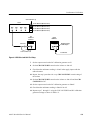
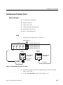
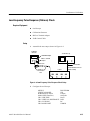
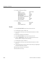
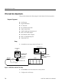
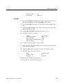
Adjustment Procedures
2. Configure the oscilloscope:
MENUS
VERTICAL MODE
HORIZONTAL DATA
MAIN SIZE(Time/div)
CH1 VERT SIZE
CH1 VERTICAL IMPEDANCE
CH1 BAND LIMIT
CH1 COUPLING
WAVEFORM
CH1
5120 pts
100 ms/div
100mV
50 W
350MHz
DC
3. Set the output of the generator for a high-amplitude signal with a 1 ms
period.
Procedure
1. Set the CH1 VOLTS/DIV control on the isolator to 1V.
2. Set the AMPLITUDE control on the calibration generator for five divisions
of display on the oscilloscope.
3. Adjust C100 on the A10 board so that the waveform displayed on the
oscilloscope is flat-topped.
4. Repeat steps 1 through 3 for all channels.
5. Disassemble the test setup.
6. Perform every procedure written in the ”Performance Verification” section of
this manual to confirm the accurate adjustment.
7-10
A6907 & A6909 Service Manual