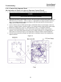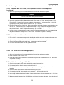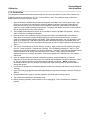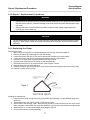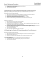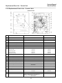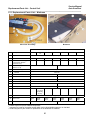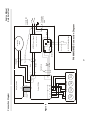
1
Auto SureFloat™
Floatation Pressure Management
with Alternating Pressure and Active Sensor Technology™
•
REF C1000MS/MES Control Unit
•
REF M1000S Series Mattress
Service Manual
P/N 11861-000 11/03
AW 5399
Before you begin…
Auto SureFloat
__________________________________________________________________________
Table Of Contents
Section
Description
Page
1.0
Warranty…………………………………………………………..……...
2
2.0
Symbols…………………………………………………………………..
2
3.0
Safety Precautions………………………………………………………
2
4.0
Description….……………………………………………….……………
3
5.0
Operator Control Panel………………………………………………….
4
6.0
Rear and Side Panel Features………………………………………….
5
7.0
Cleaning……………………………………………………………………
6
8.0
Routine Maintenance ………………………….…………………………
6
9.0
Functional Check and Safety Inspection……………………………….
7
10.0
Function Testing the M1000S Mattress ………………………………..
9
11.0
Inspection Form………….……………………………………………….
10
12.0
Troubleshooting………………………………………………………….
11
13.0
Calibration………………………………………………………………….
16
14.0
Repair / Replacement Procedures………………………………………
17
15.0
Replacement Parts Lists………………………………………………..
19
16.0
Specifications, Control Unit……………………………………………….
23
Before you begin…
Important
Review the SAFETY PRECAUTIONS in section 5.0 of this Service Manual prior to performing service.
Only qualified medical service personnel should attempt to repair this device. If you have any questions, please
contact Gaymar’s technical service department.
International Customers:
Direct
Fax:
(716) 662-8636
(716) 662-0730
Domestic Customers:
Toll Free
Fax:
(800) 828-7341 extension 739
(716) 662-8795
1
Service Manual
Warranty / Symbols / Safety Precautions
Auto SureFloat
__________________________________________________________________________
1.0
Warranty
The Control Unit is warranted free of defects in material and workmanship for a period of two (2) years.
The Mattress and Overlay are warranted free of defects in material and workmanship each for a period of one
(1) year.
The Control Unit, Mattress, and Overlay are warranted under the terms and conditions of the Gaymar warranty
in place at the time of purchase. A copy of the warranty is available upon request. Gaymar disclaims all implied
warranties including, but not limited to, the implied warranties of merchantability and of fitness for a particular
purpose.
Control Units may be returned to the factory for servicing. Contact Gaymar Technical Service for return
authorization prior to return.
Please contact Gaymar Customer Service if you have warranty questions.
Direct
Toll Free
2.0
(716) 662-2551 extension 739
(800) 828-7341
Symbols
Attention, consult accompanying documents
Type BF equipment
Dangerous voltage
Protective earth
3.0
Safety Precautions
DANGER
Risk of electric shock. Refer servicing to qualified service personnel.
WARNING
Repairs should be performed only by qualified medical equipment service personnel in
accordance with this Service manual. Otherwise, damage to the Auto SureFloat system
and improper therapy may result.
CAUTION
For grounding reliability, plug only into a properly grounded outlet.
2
Service Manual
Description
Auto SureFloat
__________________________________________________________________________
4.0 Description
The Auto SureFloat™ System is a portable air flotation system with on-demand alternating low pressure
treatment, designed to provide benefit to patients suffering from, or at risk of, developing pressure ulcers. The
system, consisting of a Control Unit and Air Flotation Mattress with it’s Top Sheet, is designed to provide
pressure management and patient comfort.
The Control Unit inflates and maintains the Mattress to user-selected settings, and can also provide on demand
alternating low pressure treatment if desired. Used with the M1000S mattress, featuring Active Sensor
Technology, the system automatically adjusts the Mattress to the optimal fill level ensuring complete flotation
pressure management.
Mattress
The Mattress base consists of twenty transverse air cells constructed of a low shear nylon. Each of the
individual cells is a minimum of eight inches tall (inflated height) and spatially oriented above a two inch
convoluted foam base. The M1000S Mattress utilizes 4 specialized air cells in the center region of the Mattress
which contain active sensors for detecting patient flotation level.
Covering the entire Mattress assembly is a low-friction, low-shear producing, vapor permeable, nylon Top
Sheet. The Top Sheet surface creates a membrane impermeable to liquids, air and bacteria though still
permeable to water vapor. Quilted onto the base of the Mattress Top Sheet is a spun bonded polyester fiberfill
that exhibits less frictional resistance to nylon than that of the patient’s skin. When the patient moves, the Top
Sheet tends to move relative to the air cells rather than relative to the patient, minimizing shearing effects.
Additionally, the quilting acts to provide a diffusion layer by which the water vapor can be drawn away from the
patient, resulting in more efficient evaporation and subsequent reduced skin maceration.
3
Service Manual
Operator Control Panel
Auto SureFloat
__________________________________________________________________________
5.0 Operator Control Panel (Figure 1)
1.
ON/STANDBY switches Control Unit between On
and STANDBY modes.
2.
POWER INDICATOR LED indicates AC power is
present to the Control Unit.
3.
MODE SELECT Press repeatedly to toggle through
operating modes, Auto/Float, Auto/A/P,
Manual/Float and Manual/A/P.
4.
SOFT (-) decreases the inflation level of the bed
while Control Unit is in manual mode only. Pressing
once will decrease the setting by one comfort level.
Pressing and holding will rapidly change the setting.
5.
COMFORT CONTROL INDICATOR displays the
current inflation level setpoint.
6.
3.1 AUTO MODE (Sensor cord from M1000S
mattress must be connected to control unit)
Mattress will automatically inflate to optimal level
based on information received from active sensors
in mattress. The indicator adjacent to the icon, will
light while automatic mode is active.
FIRM (+) increases inflation level of the bed while in
manual mode only. Pressing once will increase the
setting by one comfort level setting (~2.5mmHg).
Pressing and holding will rapidly change the setting.
7.
Note: Connecting the mattress sensor cord while
the unit is not in automatic mode will cause the
Control Unit to enter automatic mode immediately.
MAX INFLATE selects/deselects the max inflate
mode (maximum mattress firmness). The indicator
adjacent to the button will flash while max inflate
mode is active. After 30 minutes, max inflate mode
will cancel.
8.
LOCKOUT activates or cancels lockout mode.
Press and hold for three seconds to activate or
cancel mode. The indicator adjacent to the button
will light while lockout is active. In lockout mode,
only the MAX INFLATE button is operational. All
other buttons are temporarily inactive.
9.
ALARM SILENCE silences indefinitely, the audible
alarm.
If Sensor cord from mattress becomes disconnected
from control unit while in Auto mode, alarm will
sound.
3.2 MANUAL MODE Mattress inflation level userdetermined by Comfort Adjust ( - ,+ ) setting. The
indicator adjacent to the icon will light while manual
mode is active.
10. POWER FAIL INDICATOR flashes when power
supplied from line cord is interrupted while the
Control Unit is operating. To avoid an inadvertent
power fail alarm, place the unit in STANDBY mode
before disconnecting power from Control Unit.
3.3 FLOAT MODE all cells within mattress will be
uniformly inflated when this icon is illuminated.
3.4 AP MODE. (Alternating Pressure) Adjacent
cells within mattress will be alternately inflated and
deflated in this mode. The indicator adjacent to the
icon will light while AP mode is active. Note: AP
mode is temporarily suspended in max inflate mode.
4
Service Manual
Alarm Conditions / Features
Auto SureFloat
__________________________________________________________________________
5.2 Alarm Conditions
5.2.1
Unit will alarm for any of the following conditions
1
If device is unplugged while in the RUN mode, an alarm will sound for up to 20 minutes.
To correct problem, re-attach power and put unit into Standby mode, then unplug.
2
If Active Sensor cord is unplugged while in the Auto Mode, an alarm will sound
indefinitely. To correct problem, place unit in Manual mode or re-attach Active Sensor
cord.
3
If device has been running for 30 minutes and proper inflation level cannot be attained,
an alarm will sound indefinitely. To correct problem, check for disconnected or
damaged air cells or disconnected hose.
6.0 Rear and Side Panel Features (Figure 2)
1.
Hangers for attaching to footboard or side rails
on hospital bed.
2. AIR OUTLET CONNECTORS
3. MATTRESS SENSOR CORD INPUT JACK
uses feedback from M1000S mattress (with
Active Sensor Technology) for Automatic Mode
operation.
C1000MES
4. MODEL / SERIALNUMBER / IDENTIFICATION
BARCODE LABEL must not be removed from
the unit. The model and serial number
information is needed to arrange for returns to
the factory.
5. ACCESS HOLE for measuring ground line
resistance.
5
Service Manual
Cleaning / Routine Maintenance /
Auto SureFloat
__________________________________________________________________________
7.0
Cleaning
WARNING
Disconnect the AC power cord from the wall outlet before attempting to clean the control unit.
Do not heat or steam autoclave any component of the system.
1.0
To clean, use soap, water and a clean cloth to wipe down the control unit, power cord, hoses and
mattress or overlay. Do not use abrasive cleaners on the mattress. Wipe dry with a clean, dry cloth.
Note: Blood and other body fluids must be thoroughly cleaned from all surfaces before applying
disinfectants.
2.0
Apply any FDA approved disinfectant to the external surfaces of the control unit, hoses and mattress
or overlay. Allow to completely dry. The solution contact time is what makes disinfection effective.
3.0
Wipe down the mattress or overlay with a clean, dry cloth to remove any excess disinfectant.
4.0
Top sheets of mattress may also be laundered between patient uses or as required to maintain good
patient hygiene. Fill the washing machine with warm water (70 -140 °F or 21 - 60 °C). Add one cup
of laundry detergent. Place no more than four top sheets in a single extra large load capacity
washing machine. When wash cycle is complete, remove promptly from machine and ensure all
excess water is drained from load. Place dryer on LOWEST heat setting, or AIR FLUFF if available
until dry. Verify top sheet is completely dry before placing under patient.
5.0
If individual air cells of mattress become soiled, clean and disinfect as described above or simply
replace air cell with a clean replacement. Single air cell replacement can be successfully achieved
with patient remaining on the mattress. Air cells which do not contain active sensors can also be
laundered. A plug is available from Gaymar to prevent water from getting inside these during
laundering (P/N 30287).
WARNING
Do not launder the red colored Active Sensor Technology air cells of the M1000S mattress
Damage may result.
8.0 Routine Maintenance
8.1 Visual Check for Physical Damage
Visually check the unit for physical damage. Specifically inspect the power cord, power inlet connector,
mattress sensor cord input jack, bed hooks, air outlet connectors and their O-rings. Repair or replace any
broken or missing items.
6
Service Manual
Functional Check and Safety Inspection Control Unit
Auto SureFloat
__________________________________________________________________________
9.0 Functional Check and Safety Inspection
To assure optimum performance, dependability, and safety, the following should be performed annually or more
frequently if desired.
WARNING
•
Repairs should be performed only by qualified medical equipment service personnel in accordance
with this Service manual. Otherwise, damage to the Auto SureFloat system and improper therapy
may result.
•
Always perform the Functional Check and Safety Inspection after making repairs and before
returning the unit to patient use.
Inspection Form
An Inspection Form (Section 11) is provided to facilitate and document the inspection process.
Equipment or tools required:
• Current Leakage / Ground Resistance Tester
• Pressure Measurement Equipment
Part Number
Test Equipment Set 1
Adaptor (Refer to Figure 3)
11668-000
Manometer pressure gauge [0 -100 mmHg range] (Refer to Figure 3)
10392
Mattress
M1000 or M1000S Series
•
Automatic Mode Test Equipment
Mattress Sensor Test Cable
Or
Mattress
20232-001
M1000S series
Figure 3 – Test Equipment Set 1
Using M1000 Series Mattress
•
Connect pressure gauge in series between the manifold and a
blue air cell in the center of the mattress.
Using M1000S Mattress (with Active Sensor Technology Cells)
•
Connect pressure gauge in series between the manifold and
the blue air cell adjacent to the red Active Technology cells
(but the one closest to the hose end of the mattress).
7
Service Manual
Function Testing – M1000S Mattress
Auto SureFloat
__________________________________________________________________________
Test Conditions:
The following tests should be performed in a 70°F (21°C) room ambient.
Test Setup:
Attach an M1000 or M1000S Series mattress and gauge and adaptor from Test Equipment Set 1 (per Figure 3
to the control unit. Select Manual Mode with a comfort setting of 5 (half of the LED lights illuminated). It should
take approximately 10 – 15 minutes to fill.
Do not connect the mattress sensor cord of the M1000S Mattress or the Mattress Sensor Test Cable to the
unit’s input jack at this time.
9.1 Manual Mode:
1. With the unit operating in the Manual mode, press the Firm(+) button until all the LED bars are lit on the
COMFORT CONTROL INDICATOR. When pump turns off, verify the test manometer(s) reads 30 +/- 4
mmHg.
9.2 MAX INFLATE:
1. Press the MAX INFLATE button. When pump turns off, manometer should indicate pressure 2.5mmHg
greater than that measured in previous step.
9.3 AP Mode:
1. Select Manual/AP Mode with a comfort setting of 5 (half of the LED lights illuminated).
2. Allow unit to run until pump turns off and venting is complete. Record pressure in this zone.
3. Within 2½ minutes, pressure will cycle in the zone you are measuring. Again allow pump to turn off and
wait for unit to complete venting then record pressure.
4. The difference in pressure from step 3 to step 4 should be 8mmHg ±2mmHg.
9.4 Automatic Mode: (Must use M1000S series mattress or Mattress Sensor Test Cable)
1. Connect the mattress sensor cord of the M1000S Mattress or the Mattress Sensor Test Cable to the
jack on the right side panel of the control unit. This should cause the unit to enter Automatic mode by
itself.
If using the Mattress Sensor Test Cable:
•
Electrically jumper the wire ends of the Test Cable together. This simulates a bottomed patient.
Insure that the control unit responds by eventually lighting all the LED bars on the COMFORT
CONTROL INDICATOR. This may take approximately 2 - 3 minutes to occur.
•
Disconnect the jumper from the Test Cable. This simulates a lofted patient. Insure that the
control unit responds by eventually turning off all the LED bars except the bottom one. This
may take approximately 3 – 4 minutes to occur.
If using the M1000SMattress:
•
On any one of the 4 red Active Sensor Technology cells, press down so that the top surface of
the cell contacts the bottom of the cell. Insure that the control unit responds by eventually
lighting all the LED bars on the COMFORT CONTROL INDICATOR. This may take
approximately 2 - 3 minutes to occur.
•
Release hand pressure on the Active Sensor Technology cell. Insure that the control unit
responds by eventually turning off all the LED bars except the bottom one. This may take 3 – 4
minutes to occur.
8
Service Manual
Function Testing – M1000S Mattress
Auto SureFloat
__________________________________________________________________________
Note: If the unit doesn’t respond properly, suspect either a mattress failure or a control unit failure.
Rule out the mattress failure by performing the M1000S Mattress Function Test of Section 10.0
2. Press the AUTO button to exit the Automatic mode. Disconnect the mattress sensor cord or the
Mattress Sensor Test Cable from the unit .
9.5 Electrical Safety:
Perform electrical safety testing using a current leakage/ground resistance tester.
1. Current leakage values should not exceed 300 uAmps for 120V units or 500 uAmps for 230V units.
2. The line resistance between the ground pin on the power plug and its internal connection should be less
than 0.5 ohms. A hole has been provided in the back of the unit to allow access to the internal
connection for this measurement. See Figure 2.
If any of the tests outlined above were not satisfactory, the control unit should not be put into service. Refer to
the calibration and or troubleshooting sections of this manual for assistance in determining, repairing the
problem.
10.0 Function Testing – M1000S Mattress
Required Tools:
•
•
C1000MS or C1000MES control unit
ohmmeter or continuity tester
Setup:
1. Connect the mattress to the control unit. Do not connect the mattress sensor cord of the mattress to the
control unit.
2. Operate the control unit in the Manual/Float mode to inflate the mattress.
3. Allow mattress to fully inflate then connect one lead of the ohmmeter (or continuity tester) to each of the
two metal end sections of the mattress sensor cord’s phono-plug. (Figure 4)
Figure 4
10.1 Sensor Function:
1. Press down on the first of the 4 red Active Sensor Technology air cells so that the top surface of the cell
contacts the bottom of the cell. Insure that the measuring device indicates “continuity” or zero
resistance in this scenario.
2. Release hand pressure on the Active Sensor Technology cell. Insure that the measuring device now
reads “no continuity” or infinite resistance.
3. Repeat steps 1 and 2 on all four of the Active Sensor Technology cells.
9
Service Manual
Inspection Form
Auto SureFloat
__________________________________________________________________________
11.0 Inspection Form
C1000MS / MES Series Control Unit
Serial Number ____________________
Item
8.1
Physical Inspection
OK?
9.1
Manual Mode
Requirements
Yes/No
All LED bars lighted
9.2
MAX INFLATE
9.3
Automatic Mode
9.4
9.5
AP Mode
Electrical Safety
Current Leakage
Ground Resistance
Results
30 +/- 4 mmHg
Yes/No __________mmHg
~2.5mmHg > step 9.1
Yes/No ___________mmHg
Controller lights all LED bars during patient
“bottoming” simulation?
Yes/No
Controller lights one LED bar during patient
lofted” simulation?
Yes/No
Alternates every 2 minutes 30 seconds
Yes/No
Internal mattress pressure difference in A/P
cycle 8 mmHg ±2
Yes/No ___________mmHg
less than or equal to 300uA for 120V unit?
Yes/No _____________uA
less than or equal to 500uA for 230V unit?
Yes/No _____________uA
< 0.5 ohms?
Yes/No
10
Service Manual
Troubleshooting
Auto SureFloat
__________________________________________________________________________
12.0 Troubleshooting
In general, it is best to approach a problem or malfunction by first determining if the problem is due to either the
mattress or the control unit. In other words, test each independently first. Use a known good control unit, or any
other means of inflation to test the mattress.
12.1 Troubleshooting M1000S Series Mattress
Failure of the Active Sensor Technology Cells (which are specific to the M1000S mattress) requires replacement
of the entire cell assembly. See Section 10.0 for evaluation of proper functioning of these cells.
Aside from the Active Sensor Technology Cells specific to the M1000S Mattress, potential problems with the
M1000 Series mattress could include unintended leaks in the system, disconnected cells, and kinked or twisted
hoses or manifold. Troubleshooting these requires only the use of a good control unit or other device to inflate
the mattress.
Leaks in Mattress, Manifold, or hoses
Unintended leaks can be felt and heard without the use of any special equipment. There should be no
detectable air escaping from any portion of the system. Punctures or tears in any of the components should be
addressed by replacement of that component.
Disconnected Cells
Disconnected cells should be reconnected. Occasionally the white quick connect fittings can come out of the
red/orange nipples in either the cells or the manifold, and should be re-inserted with a liberal amount of
cyanoacrylate (super glue) gel adhesive on the barbs. Wipe off any excess after insertion.
Kinks/Twists in Manifold
Kinked or twisted manifolds and hoses will restrict airflow. Re-arrange components if kinks or twists are found.
11
Service Manual
Troubleshooting
Auto SureFloat
__________________________________________________________________________
12.2 Troubleshooting the Controller
Figure 5.
Suspected
control unit malfunction
Do
any of the
lights on the
operator control panel
illuminate?
N
Does
unit respond
to Active Sensors
correctly?
Refer to Section
12.2.1
Y
Does
Mattress
inflate?
N
Refer to Section
12.2.2
Y
Does
unit turn
off when
mattress is properly
inflated?
N
Refer to Section
12.2.3
N
Refer to Section
12.2.4
Y
Does
Alternating
Pressure function
properly?
12
N
Refer to Section
12.2.5
Service Manual
Troubleshooting
Auto SureFloat
__________________________________________________________________________
12.2.1 Control Unit Appears Dead
(No Indication of Power in Lights of Operator Control Panel)
1. Open unit by removing the four screws holding the front and rear enclosures together.
DANGER
Risk of electric shock when parts are electrified.
2. Apply power and test for mains voltage (120 VAC / 230 VAC) at input to AC/DC power supply, black and
white wires on 5 pin connector. See L1 in Figure 6. If appropriate line voltage is present, continue to
step 3. If no voltage is present, check power supply or wall outlet and check for loose terminals on
supply lines from power entry module.
3. Test for 12VDC at output of AC/DC power supply, red and black wires on 4 pin connector. See L2 in
Figure 6. If voltage is present, continue to step 4. If no voltage is present, replace AC/DC power supply.
4. Measure DC voltage at U7, pin 4 (L3). There should be 5.0 VDC. If, not replace Control Bd.
5. Press and hold On/Standby switch. The 5.0 VDC at pin 4 should drop to 0VDC until the switch is
released. If not, check ribbon cable connection from J2 on Main control bd to J1 on Display bd.(L4) If
ribbon cable is connected per figure 6, and voltage does not drop as indicated, replace Display bd.
6. If all of the above tests were successful, and there still is no indication of power on the display panel,
replace control bd.
Figure 6.
13
Service Manual
Troubleshooting
Auto SureFloat
__________________________________________________________________________
12.2.2 Mattress will not inflate, but Operator Control Panel Appears
Functional
1. Open unit by removing the four screws holding the front and rear enclosures together.
DANGER
Risk of electric shock when parts are electrified.
2. Insure the control unit is ON in Manual/Float mode. Does pump run? If so, proceed to step 4. If not,
test for voltage of greater than 10 VAC at the J1 connector on the control PC board, pins 1&2. See
Figure 6 (L5). If proper signal is present and pump does not turn on, replace pump assy. p/n 10325.
If proper signal is not present, replace Control PC bd. p/n 11754-000
3. Disconnect mattress from Control unit. With pump running, hold hand adjacent to hose connections on
side of unit. Is there any air flow? If so, proceed to step 5. If not, measure DC voltage at J3, across
pins 3-4 and pins 7-8. If 12VDC is not present, replace Control PC bd. If present, suspect damaged or
dirty solenoid valves. Clean or replace solenoid assy. p/n 11479-001.
4. If pump turns on yet mattress fails to inflate, check for a disconnect between each air cell and manifold
assy within mattress or damage to an air cell or hose. Reconnect or replace as necessary
12.2.3 Pump does not turn off
1. First, check for a disconnect between each air cell and manifold assy within mattress or damage to an
air cell or hose. Reconnect or replace as necessary
2. Open unit by removing the four screws holding the front and rear enclosures together.
3. Check for disconnected or pinched air lines. Reconnect or repair as necessary.
4. If all of the above items check out OK, replace Control Bd.
12.2.4 A/P Mode not functioning properly
1. Open unit by removing the four screws holding the front and rear enclosures together.
2. Refer to Section 9.4 of Function Test.
3. If unit fails function test, first check for disconnected or pinched air lines within control unit. Reconnect
or repair as necessary.
12.2.5
Unit not responding to Active Sensors
1. Check to make certain sensor cable assembly is plugged into control unit.
2. If connected, perform function test per section 9.3 and 10.1
3. If device fails function test, open unit by removing four screws holding the front and rear enclosures
together.
4. Check electrical connections on Sensor Jack assembly per Figure 8
5. If connections look OK, disconnect the 3 pin connector J5, from the main control bd.
6. Insert small leads (such as those found on 1/8 watt resistors) into end of connector at pins 1 & 3 (white
and black)
7. Measure continuity between pins 1 & 3. With no cord plugged into sensor jack assy., there should be 0
ohms resistance.
14
Service Manual
Troubleshooting
Auto SureFloat
__________________________________________________________________________
8. If connection is open, replace sensor jack assy.. If OK, connect mattress sensor test cable 20232-001
to sensor jack assy
9. With the ends of the test cable not jumpered together, there should be no continuity (open) between
pins 1 & 3.
10. Now check continuity between pins 2 & 3. With the ends of the test cable not jumpered together, there
should be no continuity (open)
11. Electrically jumper the ends of the test cable together. There should be continuity between pins 2 & 3.
12. If not, replace sensor jack assy.
13. If everything checks out and unit will still not pass section 9.3 of function test, replace main control bd.
15
Service Manual
Calibration
Auto SureFloat
__________________________________________________________________________
13.0 Calibration
The calibration procedure should only be performed if the unit does not pass the Function Test of Section 9.0.
Calibration should be performed in a 70°F (21°C) room ambient. Note: The calibration target numbers are
different than the nominal verification values.
1. Attach an M1000 or M1000S Series mattress and gauge and adaptor from Test Equipment Set 1 (per
Figure 3) to the control unit and allow the system to operate for at least 15 minutes in Manual/Float
mode with one half (5) of the LED lights on the COMFORT CONTROL INDICATOR lit (to allow the
system to come to stable operating temperatures). The gauge and adaptor should be in series with the
first air cell (from the foot end) in the mattress.
2. The M1000S Series mattress is broken up into two distinct zones to facilitate A/P operation. Zones A
and B. Each zone is calibrated individually.
3. Enter the control unit’s calibration mode by pressing and holding, for approximately 3 seconds, the
Alarm Silence and Lockout buttons WHILE plugging the control unit into the wall outlet. (you must
continue to hold the buttons until the unit beeps). After releasing the buttons, the unit will display 5 LED
lights on the COMFORT CONTROL INDICATOR while alternately flashing the On/Standby and Lock
lights. The A/P light will also be illuminated indicating that the unit is ready for calibration information for
Zone A.
4. The control unit will attempt to fill both Zones to 15mmHg. Allow control unit to fill mattress until pump
turns off. Check the gauge. It should read 15mmHg. If not, repeatedly pressing the – Soft or + Firm
buttons will increment the pressure in 0.5mmHg increments. (example: measurements indicate internal
mattress pressure of 18 mmHg. press soft button 6X to correct) If, after making the necessary
adjustments, there is no change in pressure, reconnect the gauge to the adjacent cell in the mattress
and repeat.
5. Once the mattress has been adjusted to the proper pressure, press the Mode key to conclude
calibration of Zone A and store the values. The controller will immediately commence calibration of Zone
B. The A/P indicator should turn off and the Manual indicator should light. (NOTE: pressing the
On/Standby button at any time during this procedure will result in exit from the cal procedure without
storing new values.)
6. Re-connect the gauge to an immediately adjacent cell within the mattress and allow unit to fill Zone B to
15mmHg.
7. Again check the gauge pressure and make adjustments per step 4 as necessary to achieve 15mmHg in
Zone B.
8. Press the Mode button again to conclude calibration of Zone B and store these values.
9. The unit will automatically go into Standby mode.
10. Before resuming operation, remove power to unit by unplugging. This will conclude the calibration
process.
16
Service Manual
Repair / Replacement Procedures
Auto SureFloat
__________________________________________________________________________
14.0 Repair / Replacement Procedures
WARNING
•
Repairs should be performed only by qualified medical equipment service personnel in accordance
with this Service manual. Otherwise, damage to the Auto SureFloat system and improper therapy
may result.
•
Always perform the Functional Check and Safety Inspection after making repairs and before
returning the unit to patient use.
CAUTION
The PC boards within the control unit contain electronic components that are highly sensitive to static
discharge. Wear a static control device (grounding strap) when inside the unit to event electrostatic
discharge.
14.1 Replacing the Pump
Removing the pump:
1. Open unit by removing the four screws holding the front and rear enclosures together.
2. Remove the Sensor jack assembly from the rear housing.
3. Loosen and remove the two 1/8” hex screws that anchor the base to the rear housing.
4. Loosen and remove the two 3/8” ground nuts and disconnect all 4 ground wires.
5. Cut wire tie on output hose of pump and disconnect output tubing.
6. Remove screw securing ferrite ring clamp to solenoid assembly.
7. Disconnect wires from J1 on main control bd. (refer to figure 7 below)
8. Remove ferrite ring from wires and save.
9. Carefully lift base to gain access to the 4 cross-recess screws securing the pump to the rear housing.
10. Remove 4 screws securing pump.
Figure 7
Installing the replacement:
1. Loop wires from pump through ferrite ring 3X and leave approximately 4” of wire between pump and
ferrite ring.
2. Attach new pump to rear housing using 4 cross-recess screws.
3. Secure base to rear housing. Note: when securing ground lug, make certain to use one nut to secure
base, next place a lockwasher over stud, then attach the 4 ground wires and finally the last ground nut.
4. Attach wires to J1 on main control bd per wiring diagram, figure 8
5. Secure ferrite clamp to solenoid assembly.
17
Service Manual
Repair / Replacement Procedures
Auto SureFloat
__________________________________________________________________________
6. Reattach hose to output of pump and secure with wire tie.
7. Re-attach sensor jack assembly.
8. Close and secure enclosure.
14.2 Replacing the Control PC Board Assembly (in Rear Enclosure)
Replacing the Control PC board assembly will require re-calibration of the unit per section 13.
Removing the Control PC Board Assembly:
1. Open unit by removing the four screws holding the front and rear enclosures together.
2. Disconnect the 2 wire connectors, J4 and J2 from the PC board.
3. Disconnect the individual wires from terminal blocks at J1, J3 and J5.
4. Remove tubing from pressure transducers on pc bd.
5. Remove 4 screws securing pc bd to base of rear enclosure and remove pc bd.
Installing the replacement:
1. Place the new PC board on the mounting standoffs.
2. Secure board to the standoffs with four screws.
3. Reconnect the 2 wire connectors to the PC board. When re-attaching the ribbon cable at J2, make
certain ribbon cable is pointing down (toward pump).
4. Re-connect individual wires to terminal blocks following connection diagram, figure 8
5. Re-connect tubing to pressure transducers. The shorter of the two lengths of tube gets connected to
PS1 and the longer length to PS2.
6. Close and secure enclosure.
7. Unit must now be calibrated per section 13.0 above
14.3 Replacing the Display PC Board Assembly (in Front Enclosure)
Removing the Display PC Board Assembly
1. Open unit by removing the four screws holding the front and rear enclosures together.
2. Disconnect ribbon cable from J1
3. Remove 5 nuts securing pc bd assembly to front enclosure and extract pc bd..
Installing the replacement:
1. Place the new pc bd over mounting studs and secure with mating nuts
2. Re-attach ribbon cable with ribbon pointing away from front enclosure.
3. Close and secure enclosure.
18
Service Manual
Replacement Parts List – Control Unit
Auto SureFloat
__________________________________________________________________________
15.0 Replacement Parts List – Control Unit
Control Unit
No.
Description
C1000MS
C1000MES
Main Control Bd
11754-000
11754-000
2
Display Bd
11753-000
11753-000
3
DC Power Supply
91565-000
91565-000
4
Solenoid Valve Assembly
11479-001
11479-001
5
Sensor Jack Assembly
11782-000
11782-000
6
Pump
10325
10325
7
Ribbon Cable Assembly
10364-18
10364-18
1
8
Ferrite Core (Flat ribbon cable)
91390-021
91390-021
8A-Pump wires
91390-005
91390-005
8B-DC Supply wires
91390-004
91390-004
8C-AC power wires
91390-004
91390-004
8D-Sensor Jack wires
91390-012
91390-012
9
Front housing
20213
20213
10
Rear housing
11777-000
11777-002
11
Screws for enclosure
10363 (4)
10363 (4)
12
Operator Control Panel Label (not shown)
12070-000
12070-000
13
Logo Label (not shown)
12070-000
12070-000
14
Bed hook (2 per unit) (not shown)
15
Air outlet fittings
30297
30297-IT
10044 Male
10037 Male (2)
10045 Female
16
Power Entry Filter
91368-005
91368-005
17
Backing Plate
11726-000
11726-000
18
Air Tubing
5/32ID 10140
5/32ID 10140
¼ ID 10178
¼ ID 10178
50041
50041
19
CPR Label
Power Cord
USA – PC008,Continental Europe – PC001, United
Kingdom – PC002, Australia – PC003, Switzerland –
PC004, Italy – PC005, Denmark – PC006
Israel – PC007
19
PC005
Service Manual
Replacement Parts List – Control Unit
Auto SureFloat
__________________________________________________________________________
15.1 Replacement Parts List – Mattress
Manifold Assembly
Mattress
†
Mattress Size
No.
Description
M1000S
M1000SE32
M1000S-39
1
Top sheet*
2
Air cell
30005
30005-32
30005-39
30005-42
3
Active Sensor Technology
cell assembly (M1000S
mattresses only)
30310
30310-32
30310-39
30310-42
4
Manifold assy (includes
items 5-12, 16)
M1000S-54
M1000S-60
30005-48
30005-54
30005-60
30310-48
30310-54
30310-60
11815-000 M1000S
Manifold tubing
6
Manifold
7
Quick Connect - female
10044-000
8
Quick Connect - male
10045-000
9
Hose adaptor
11813-000
10
Hose Sleeve
11
Quick Connect - female
13
M1000S-48
30006-XXX (size or logo dependant)
5
12
M1000S-42
11888-000 M1000SE-32 only
10035 by the foot
11887-000
30159
10057 (2)
Clamp
Base
20045 & 20046 & 10116
30065
30065-32
30065-39
30065-42
30065-48
30065-54
30065-60
30065FC54
30065FC60
(11716-32
M1000SE‡
32 only)
14
Foam
15
Foam cover
16
Label
20001 (specify width)
30065FC
30065
FC32
30065FC39
30065FC42
30065FC48
12073
* contact Gaymar for private labeled components
†
mattress size is part of the model number which can be found inside mattress or on law label
‡
contact Gaymar for part number of replacement in the M1000SE-32 mattress
20
Figure 8
Split Ferrite
J3
Control PC Bd
J2
Zone A
Fill
J1
Zone B
Fill
Zone A
Vent
Solenoid Manifold
1 2 3 4 5 6 7 8
Loop through
core 2X
J1
Display PC Bd
Zone B
Vent
3
J5 2
1
+
J4
2
1
Black
Red
White
Ferrite Core
Black
Red
Air Pump
12VAC
N/C
Fuses - (2) T, 2.5A/250V
AC/DC Power Supply
grn
21
To display
bd backing
plate
110-240 VAC
50/60 Hz
P1000MS/MES Connection Diagram
M1000S Series Mattress
Bottoming Sensor
Bottoming Sensor Jack
Ferrite Cores
Loop through
core 3X
Service Manual
Connection Diagram
Auto SureFloat
_____________________________________________________________________________________________________
Service Manual
Pneumatic connections
Auto SureFloat
__________________________________________________________________________
Pneumatic profile
Main Control PC bd
Figure 9
Solenoid Assy.
Output to
Mattress
Pump Assy.
22
16.0 Specifications, Control Unit
C1000MES
Enclosure Dimensions
10" x 12" x 4-1/2"
(25 cm x 30 cm x 11 cm)
Weight
Power Cord
9.5 pounds (4.3 kg)
Detachable 14’ , #18 AWG minimum, with ground wire
Overcurrent Protection
Primary
2.5A, 250V, T
Input
Operating Ambient
Temperature Range
Classification
120 -230 VAC, 50/60Hz, 120V – 0.44A, 230V – 0.33A
60 to 85°F (16 to 29°C)
Class I grounded equipment not suitable for use in the presence of a
flammable anesthetic mixture with air or with oxygen or nitrous oxide.
Type BF equipment
UL2601-1, CSA C22.2 NO. 601.1-M90
EN 60601-1
`
Continuous operation
Electromagnetic
Compatibility
Meets EN60601-1-2:2001
(CISPR 11 Classified as Class B, Group 1 ISM equipment)
23
10 Centre Dr.
Orchard Park, New York
14127-2295
Phone
1-800-828-7341
716-662-2551
Authorized CE representative:
(Europe):
INVATECH GmbH & Co.
Wandsbeker Königstraβe 27-29
D 22041 Hamburg, Germany
24