1
Operation
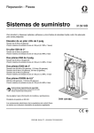
1:1 Extruder
310726H
Supply, metering and dispense system for 5 gallon (20 Liter) pails. For professional use
only.
Not approved for use in European explosive atmosphere locations.
Part No. 965119
1:1 Extruder President® Check-Mate® 200 System, carbon steel
Part No. 570135
1:1 Extruder President® Check-Mate® 200 System, stainless steel
2000 psi (14 MPa, 140 bar) Pump Maximum Working Pressure
90 psi (621 kPa, 6.3 bar) Pump Maximum Air Inlet Pressure
150 psi (1 MPa, 10 bar) Ram Maximum Air Inlet Pressure
Important Safety Instructions
Read all warnings and instructions in this
manual. Save these instructions.
Table Of Contents
Warnings . . . . . . . . . . . . . . . . . . . . . . . . . . . . . . . . . . . . . . . 2
Grounding . . . . . . . . . . . . . . . . . . . . . . . . . . . . . . . . . . . . . . 4
Operation . . . . . . . . . . . . . . . . . . . . . . . . . . . . . . . . . . . . . . 4
Pressure Relief Procedure . . . . . . . . . . . . . . . . . . . . . . 5
Initial Startup . . . . . . . . . . . . . . . . . . . . . . . . . . . . . . . . . 5
Dispensing Mixed Material . . . . . . . . . . . . . . . . . . . . . . 5
Shutdown . . . . . . . . . . . . . . . . . . . . . . . . . . . . . . . . . . . 5
Part No. 965119 . . . . . . . . . . . . . . . . . . . . . . . . . . . . . . . . . 6
Part No. 965119 . . . . . . . . . . . . . . . . . . . . . . . . . . . . . . . . . 7
Part No. 570135 . . . . . . . . . . . . . . . . . . . . . . . . . . . . . . . . . 8
Part No. 570135 . . . . . . . . . . . . . . . . . . . . . . . . . . . . . . . . . 9
Technical Specifications . . . . . . . . . . . . . . . . . . . . . . . . . 10
Part No. 570135 . . . . . . . . . . . . . . . . . . . . . . . . . . . . . 10
Part No. 965119 . . . . . . . . . . . . . . . . . . . . . . . . . . . . . 10
Mounting Footprint . . . . . . . . . . . . . . . . . . . . . . . . . . . . . 11
Part No. 570135 and 965119 . . . . . . . . . . . . . . . . . . . 11
Graco Standard Warranty . . . . . . . . . . . . . . . . . . . . . . . . 12
Graco Information . . . . . . . . . . . . . . . . . . . . . . . . . . . . . . 12
EN
Warnings
Warnings
The following warnings are for the setup, use, grounding, maintenance, and repair of this equipment. The exclamation point symbol alerts you to a general warning and the hazard symbols refer to procedure-specific risks. When
these symbols appear in the body of this manual or on warning labels, refer back to these Warnings. Product-specific
hazard symbols and warnings not covered in this section may appear throughout the body of this manual where
applicable.
WARNING
SKIN INJECTION HAZARD
High-pressure fluid from gun, hose leaks, or ruptured components will pierce skin. This may look like just
a cut, but it is a serious injury that can result in amputation. Get immediate surgical treatment.
• Do not point gun at anyone or at any part of the body.
• Do not put your hand over the spray tip.
• Do not stop or deflect leaks with your hand, body, glove, or rag.
• Do not spray without tip guard and trigger guard installed.
• Engage trigger lock when not spraying.
• Follow Pressure Relief Procedure in this manual, when you stop spraying and before cleaning,
checking, or servicing equipment.
FIRE AND EXPLOSION HAZARD
Flammable fumes, such as solvent and paint fumes, in work area can ignite or explode. To help prevent
fire and explosion:
• Use equipment only in well ventilated area.
• Eliminate all ignition sources; such as pilot lights, cigarettes, portable electric lamps, and plastic drop
cloths (potential static arc).
• Keep work area free of debris, including solvent, rags and gasoline.
• Do not plug or unplug power cords, or turn power or light switches on or off when flammable fumes
are present.
• Ground equipment and conductive objects in work area. See Grounding instructions.
• Use only grounded hoses.
• Hold gun firmly to side of grounded pail when triggering into pail.
• If there is static sparking or you feel a shock, stop operation immediately. Do not use equipment
until you identify and correct the problem.
EQUIPMENT MISUSE HAZARD
Misuse can cause death or serious injury.
• Do not exceed the maximum working pressure or temperature rating of the lowest rated system
component. See Technical Data in all equipment manuals.
• Use fluids and solvents that are compatible with equipment wetted parts. See Technical Data in all
equipment manuals. Read fluid and solvent manufacturer’s warnings.
• Check equipment daily. Repair or replace worn or damaged parts immediately.
• Do not alter or modify equipment.
• For professional use only.
• Use equipment only for its intended purpose. Call your Graco distributor for information.
• Route hoses and cables away from traffic areas, sharp edges, moving parts, and hot surfaces.
• Do not use hoses to pull equipment.
• Comply with all applicable safety regulations.
2
310726H
Warnings
WARNING
MOVING PARTS HAZARD
Moving parts can pinch or amputate fingers and other body parts.
• Keep clear of moving parts.
• Do not operate equipment with protective guards or covers removed.
• Pressurized equipment can start without warning. Before checking, moving, or servicing equipment,
follow the Pressure Relief Procedure in this manual. Disconnect power or air supply.
TOXIC FLUID OR FUMES HAZARD
Toxic fluids or fumes can cause serious injury or death if splashed in the eyes or on skin, inhaled, or
swallowed.
• Read MSDS’s to know the specific hazards of the fluids you are using.
• Store hazardous fluid in approved containers, and dispose of it according to applicable guidelines.
PERSONAL PROTECTIVE EQUIPMENT
You must wear appropriate protective equipment when operating, servicing, or when in the operating
area of the equipment to help protect you from serious injury, including eye injury, inhalation of toxic
fumes, burns, and hearing loss. This equipment includes but is not limited to:
• Protective eyewear
• Clothing and respirator as recommended by the fluid and solvent manufacturer
• Gloves
• Hearing protection
310726H
3
Grounding
Grounding
To maintain grounding continuity when flushing or
relieving pressure: hold metal part of the spray
gun/dispense valve firmly to the side of a grounded
metal pail, then trigger the gun/valve.
WARNING
Your system must be grounded. Read warnings, page
2.
Pump: use ground wire and clamp. Loosen grounding
lug locknut (A) and washer (B). Insert 12 gauge minimum ground wire end (D) into lug slot (C) and tighten
locknut securely. Connect ground clamp to a true earth
ground.
Air and fluid hoses: use only electrically conductive
hoses. Check electrical resistance of hoses once a
week. Refer to the hose tag or contact supplier for maximum resistance limits. If total resistance to ground
exceeds limits, replace hose immediately.
D
Operation
WARNING
Keep your fingers, hands, and tools away from the
priming piston and the air motor piston during operation and whenever the pump air and fluid pressure is
not fully relieved. The pump priming piston extends
below the foot valve during operation and could pinch
or amputate your fingers or hands as it moves up into
the cylinder.
Be sure all moving part shields are installed and safety
devices are operating properly before each use.
WARNING
C
B
A
FIG. 1
Air compressor: follow manufacturer’s recommendations.
Spray gun / Dispense valve: ground through connection to a properly grounded fluid hose and pump.
Fluid supply container: follow local code.
Object being sprayed: follow local code.
Tighten all fluid connections securely before each use.
High pressure fluid can dislodge a loose coupling or
allow high pressure spray to be emitted from the coupling.
CAUTION
Never operate one pump alone. Do not disconnect
one pump or allow a pump to run out of material. The
system is designed to have both pumps run together.
Running one pump alone puts too much stress on the
hardware that connects the air motor to the displacement pumps and could cause the hardware to fracture.
Solvent pails used when flushing: follow local code.
Use only conductive metal pails, placed on a grounded
surface. Do not place the pail on a nonconductive surface, such as paper or cardboard, which interrupts
grounding continuity.
4
310726H
Operation
Pressure Relief Procedure
WARNING
Follow Pressure Relief Procedure when you stop
dispensing and before cleaning, checking, or servicing
equipment. Read warnings, page 2.
1. Engage trigger lock.
2. Turn off air to the pump air motor.
3. Disengage the trigger lock.
4. Hold a metal part of the gun firmly to a grounded
metal pail. Trigger the gun to relieve pressure.
6. Stand clear of the pumps. Turn the ram control to
DOWN. When the ram plates enter the pails and
material comes out the vents, close the vent valves.
Set the ram down pressure to at least 50 psi (345
kPa, 3.4 bar). More pressure can be used for high
viscosity materials.
7. Remove the mixer if one is installed.
8. Open the outlet valves on the hoses.
9. Set the President air motor regulator to 40 psi (276
kPa, 2.8 bar). Slowly open the pump control air
valve just until the pumps start moving. (Some air
will escape while the valve is partially open.) When
the pumps are primed and filling the hoses, the
pump control air valve can be fully opened. When
both materials are coming through the outlets free
of test oil, close the dispense valve.
5. Engage the trigger lock.
6. Open all fluid drain valves in the system, having a
waste container ready to catch drainage. Leave
drain valve(s) open until you are ready to dispense
again.
7. If you suspect the spray tip or hose is clogged or
that pressure has not been fully relieved after following the steps above, VERY SLOWLY loosen tip
guard retaining nut or hose end coupling to relieve
pressure gradually, then loosen completely. Clear
hose or tip obstruction.
Initial Startup
1. Connect a 1/2 in. (12.7 mm) air hose to the main air
inlet connection.
2. Connect the dispense valve kit.
Dispensing Mixed Material
1. Install a mixer on the outlet valve.
2. Set pump motor valve to the ON position.
3. Open dispense valve. Adjust President air motor
regulator from 40–120 psi (0.28–0.8 MPa, 2.8–8
bar) to obtain desired flow rate.
Shutdown
When you are done dispensing, remove the disposable
mixer, and wipe off the outlet. Depending on what type
of material you are dispensing, it may be better to leave
the mixer on until the next time you use the equipment,
or it may be necessary to not only wipe off the outlet but
to seal it from air. Part No. 551327 plastic disposable
caps are available for this purpose.
3. Raise the pneumatic ram:
a. Turn the ram control to UP.
b.
Turn the ram air regulator up until the pumps
begin to rise.
4. Open a pail of component A and B. Place the pails
in their proper spots on the frame assembly pail levelers. Hook the pail handles over the nearby frame
bolts.
5. Open the pail ram plate vent valves.
310726H
5
Part No. 965119
Part No. 965119
23
78
43,75
61
68
32
11,10
45
47
42
25
76
69
58
13
13
1
50
51
5
59
12
28
29
27
20
70
2
15
52
53
74
67
62
3
33
35
49
18,26
48
36
41
73,72,71 16 38
14 39
Front
View
81
37
40
4
54
24
60
7
9
6
7
14
30
17,15
21,86
55,87,88
56
34
12
57
58
23
19
22
8
58
6
Side View
310726H
Part No. 965119
Part No. 965119
Ref.
No.
1
2
3
4
5
6
7
8
9
10
11
12
13
14
15
16
17
18
19
20
21
22
23
25
26
27
28
29
30
31
32
33
34
35
36
37
38
39
40
41
42
43
45
47
48
49
50
51
52
53
54
55
Part No.
100060
100018
100122
113264
100361
108638
100840
100896
100960
101533
101535
103475
625077
101959
102814
104594
100206
208391
156684
156823
156971
157191
158212
158683
100195
184100
184160
184131
171937
206995
24B229
511174
220179
222771
222812
502524
512004
512171
590385
623533
624909
167646
624913
902413
947917
257461
948617
513649
100128
513623
C19391
513004
310726H
Description
Qty.
SCREW, cap hex head
3
WASHER, lock spring
3
NIPPLE, close
1
CROSS, pipe
1
PLUG, pipe
1
TEE, pipe
2
ELBOW, street
2
FITTING, bushing pipe
2
GAUGE, press air
1
WASHER, spring lock
6
NUT, full hex
6
TEE, pipe
3
ROD, tie 1:1 extruder
6
ELBOW, cprsn male
2
GAUGE, press fluid
2
SCREW, cap
8
BUSHING, pipe
2
VALVE, ball
2
UNION, adapter
2
UNION, swivel
1
NIPPLE, short
2
FITTING, adapter; 1/2 npt x 3/4 npt 2
BUSHING
3
FITTING, elbow 90°
1
NIPPLE, pipe
2
NUT, coupling
2
ROD, adapter
2
COLLAR, coupling
4
REGULATOR, air
1
FLUID, TSL 1 qt.
1
MOTOR, Air pres
1
FITTING, airline
1
VALVE, check
2
PUMP, shovel
2
PLATE, wiper, 5 gallon
2
FITTING, connector tube
1
CYLINDER, air/ 2” stroke
2
SCREW, machine, socket HD
2
TUBE, poly-flo
10
PLATE, pail/ram
2
PLATE, tie 1:1 Extrud. Checkmate
1
BEAM, ram
1
ROD, tie ram 1:1 extruder
2
KIT, repair
1
FRAME, pail locator
1
RAM, 55 gal, bare 3 in. pneumatic
1
YOKE, extruder 1:1
1
BEARING, cam follower
2
WASHER, lock
1
SCREW, cap socket HD
1
FITTING, elbow
1
VALVE, directional air 1/4 in. NPT
1
Ref.
No.
56
57
58
59
60
61
62
65▲
66▲
67
68
69
70
71
72
73
74
75
76
77
78
81
86
87
88
Part No. Description
512910 MUFFLER, polyethylene 1/4 in.
NPT
113034 FITTING, tube, straight
205437 COUPLING, hose
162449 FITTING, nipple reducing
206727 VALVE, release air
061132 HOSE, nylon
109209 NUT, lock hex
180233 LABEL, warning
513106 LABEL, warning
624944 SPACER, pump
208048 HOSE, coupled
102478 STRAP, tie wiring
166361 EMBLEM, Graco
100004 SCREW, cap hex head
100731 WASHER
100133 WASHER, lock
625286 SHIELD, yoke 1:2 extruder
189559 CAP, end
15W561 UNION, swivel 90°
184119 WRENCH, packing nut
165188 EMBLEM, Graco
100451 COUPLING
C12509 HOSE, 1/4 OD
107445 SCREW, cap
100016 WASHER, lock
Repair Parts
207385
222785
222786
222784
184101
184106
222798
Qty.
1
1
4
1
2
20
6
4
1
1
1
10
1
4
4
4
1
2
1
1
1
2
1
2
2
Motor Seal Kit
Throat Packing Kit (UHMW & PTFE)
Throat Packing Kit (PTFE)
Pump Seal Kit (Less Throat)
Replacement Rod
Replacement Cylinder
Inlet Seat Kit (Seat & O-ring)
▲ Replacement Danger and Warning labels, tags, and
cards are available at no cost.
7
Part No. 570135
Part No. 570135
96
25
97
43,75
95
47
1
33
94
61
32
11,10
69
45
66
93
42
13
59
60
92,89
87
5
2
13
50
51
28
27
15
35
48
41
52 65
53
29
3
33
74
67
70
49
36
62
73,72,71
Front View
16
38 14
37
40
39
20
4
54
7 6
14
54,22
55,23,24
60
9
7
56
57
30
17,15
12
34
88
Side View
8
310726H
Part No. 570135
Part No. 570135
Ref.
No.
1
2
3
4
5
6
7
9
10
11
12
13
14
15
16
17
20
22
23
24
25
27
28
29
30
31
32
33
34
35
36
37
38
39
40
41
42
43
45
47
48
49
50
51
52
53
54
55
56
57
59
60
Part No.
100060
100018
100122
113264
100361
108638
100840
100960
101533
101535
502570
625077
101959
513432
104594
102022
156823
C12509
107445
100016
158683
184100
184160
184131
171937
206995
24B229
511174
501603
222814
222909
502524
512004
512171
590385
623533
624909
167646
624913
902413
947917
257461
948617
513649
100128
513623
C19391
513004
512910
Description
Qty.
SCREW, cap hex head
3
WASHER, lock spring
3
NIPPLE, close
1
CROSS, pipe
1
PLUG, pipe
1
TEE, pipe
1
ELBOW, street
6
GAUGE, press air
1
WASHER, spring lock
6
NUT, full hex
6
FITTING, tee 1/2 NPT
2
ROD, tie 1:1 extruder
2
ELBOW, cprsn male
2
GAUGE, press fluid SST
2
SCREW, cap
8
BUSHING, pipe
2
UNION, swivel
1
HOSE, 1/4 OD
1
SCREW, cap
2
WASHER, lock
2
FITTING, elbow 90°
1
NUT, coupling
2
ROD, adapter
2
COLLAR, coupling
4
REGULATOR, air
1
FLUID, TSL 1 qt. (not shown)
1
MOTOR, air president
1
FITTING, airline
2
VALVE, check 1/2 in. NPT SST
2
PUMP, shovel SST
2
PLATE, wiper, 5 gallon
2
FITTING, connector tube
1
CYLINDER, air/ 2 in. stroke
2
SCREW, machine, socket HD
2
TUBE, poly-flo
10
PLATE, pail/ram
2
PLATE, tie 1:1 Extrud. Checkmate
1
BEAM, ram
1
ROD, tie ram 1:1 extruder
2
KIT, repair
1
FRAME, pail locator
1
RAM, 55 gal, bare 3 in. pneumatic
1
YOKE, extruder 1:1
1
BEARING, cam follower
2
WASHER, lock
1
SCREW, cap socket HD
1
FITTING, elbow
1
VALVE, directional air 1/4 in. NPT
1
MUFFLER, polyethylene 1/4 in.
1
NPT
113034 FITTING, hose, straight
1
162449 FITTING, nipple reducing
1
206727 VALVE, release air
2
310726H
Ref.
No.
61
62
65▲
66▲
67
69
70
71
72
73
74
75
87
88
89
92
93
94
95
96
97
98
Part No.
208048
109209
180233
513106
624944
102478
166361
100004
100731
100133
625286
189559
C20432
552049
100206
111697
104172
590332
158212
15W561
165188
184119
Repair Parts
207385
222785
222786
222784
184101
184106
222798
Description
Qty.
HOSE, coupled
1
NUT, lock hex
6
LABEL, warning
4
LABEL, warning
1
SPACER, pump
1
STRAP, tie wiring
10
EMBLEM, Graco
1
SCREW, cap hex head
4
WASHER
4
WASHER, lock
4
SHIELD, yoke 1:1 extruder
1
CAP, end
2
FITTING, cross pipe
1
COUPLING, 1/2 in. NPT SST
2
BUSHING, pipe
1
PLUG, pipe
1
FITTING, tube
2
TUBE, poly-flo5/32ID x 1/4OD
15
BUSHING
1
UNION, swivel 90°
1
EMBLEM, Graco
1
WRENCH, packing nut (not shown) 1
Motor Seal Kit
Throat Packing Kit (UHMW & PTFE)
Throat Packing Kit (PTFE)
Pump Seal Kit (Less Throat)
Replacement Rod
Replacement Cylinder
Inlet Seat Kit (Seat & O-ring)
▲ Replacement Danger and Warning labels, tags, and
cards are available at no cost.
9
Technical Specifications
Technical Specifications
Part No. 570135
Mix ratio by volume . . . . . . . . . . . . . . . . .
Pressure Ratio (Fluid/Air) . . . . . . . . . . . . .
Volume Output per cycle . . . . . . . . . . . . .
Air Motor Diameter. . . . . . . . . . . . . . . . . .
Air Consumption. . . . . . . . . . . . . . . . . . . .
Air Inlet . . . . . . . . . . . . . . . . . . . . . . . . . .
Fluid Outlets . . . . . . . . . . . . . . . . . . . . . .
Wetted Parts . . . . . . . . . . . . . . . . . . . . . .
1:1
22:1
2.9 fl. oz.
Ø4.25
10 cfm
1/2 npsm(f)
1/2 or 3/8 npt(f)
Stainless Steel, PTFE, UHMW
Polyethylene
Maximum Air Working Pressure . . . . . . . . . 90 psi (6.3 bar, .63 mPa)
Maximum Temperature . . . . . . . . . . . . . . . Ambient
Maximum Fluid Working Pressure . . . . . . . 2000 psi (140 bar, 14.0 mPa)
Weight . . . . . . . . . . . . . . . . . . . . . . . . . .
500 lbs (227 kg)
Part No. 965119
Mix Ratio by Volume . . . . . . . . . . . . . . . . .
Pressure Ratio (fluid/air) . . . . . . . . . . . . .
Volume Output per cycle . . . . . . . . . . . . .
Air Motor Diameter. . . . . . . . . . . . . . . . . .
Air Consumption. . . . . . . . . . . . . . . . . . . .
Air Inlet. . . . . . . . . . . . . . . . . . . . . . . . . .
Fluid Outlets . . . . . . . . . . . . . . . . . . . . . .
Wetted Parts . . . . . . . . . . . . . . . . . . . . . .
1:1
22:1
2.9 fl. oz.
Ø4.25
10 cfm
1/2 npsm(f)
1/2 or 3/8 npt(f)
Carbon Steel, Stainless Steel, Ductile Iron, Zinc and Nickel Plating,
PTFE, UHMW Polyethylene
Maximum Air Working Pressure . . . . . . . . . 90 psi (6.3 bar, .63 mPa)
Maximum Temperature . . . . . . . . . . . . . . . Ambient
Maximum Fluid Working Pressure . . . . . . . 2000 psi (140 bar, 14.0 mPa)
Weight . . . . . . . . . . . . . . . . . . . . . . . . . .
500 lbs (227 kg)
10
310726H
Mounting Footprint
Mounting Footprint
Part No. 570135 and 965119
42
2
.56 Holes
2
25
310726H
11
Graco Standard Warranty
Graco warrants all equipment referenced in this document which is manufactured by Graco and bearing its name to be free from defects in
material and workmanship on the date of sale to the original purchaser for use. With the exception of any special, extended, or limited warranty
published by Graco, Graco will, for a period of twelve months from the date of sale, repair or replace any part of the equipment determined by
Graco to be defective. This warranty applies only when the equipment is installed, operated and maintained in accordance with Graco’s written
recommendations.
This warranty does not cover, and Graco shall not be liable for general wear and tear, or any malfunction, damage or wear caused by faulty
installation, misapplication, abrasion, corrosion, inadequate or improper maintenance, negligence, accident, tampering, or substitution of
non-Graco component parts. Nor shall Graco be liable for malfunction, damage or wear caused by the incompatibility of Graco equipment with
structures, accessories, equipment or materials not supplied by Graco, or the improper design, manufacture, installation, operation or
maintenance of structures, accessories, equipment or materials not supplied by Graco.
This warranty is conditioned upon the prepaid return of the equipment claimed to be defective to an authorized Graco distributor for verification of
the claimed defect. If the claimed defect is verified, Graco will repair or replace free of charge any defective parts. The equipment will be returned
to the original purchaser transportation prepaid. If inspection of the equipment does not disclose any defect in material or workmanship, repairs will
be made at a reasonable charge, which charges may include the costs of parts, labor, and transportation.
THIS WARRANTY IS EXCLUSIVE, AND IS IN LIEU OF ANY OTHER WARRANTIES, EXPRESS OR IMPLIED, INCLUDING BUT NOT LIMITED
TO WARRANTY OF MERCHANTABILITY OR WARRANTY OF FITNESS FOR A PARTICULAR PURPOSE.
Graco’s sole obligation and buyer’s sole remedy for any breach of warranty shall be as set forth above. The buyer agrees that no other remedy
(including, but not limited to, incidental or consequential damages for lost profits, lost sales, injury to person or property, or any other incidental or
consequential loss) shall be available. Any action for breach of warranty must be brought within two (2) years of the date of sale.
GRACO MAKES NO WARRANTY, AND DISCLAIMS ALL IMPLIED WARRANTIES OF MERCHANTABILITY AND FITNESS FOR A
PARTICULAR PURPOSE, IN CONNECTION WITH ACCESSORIES, EQUIPMENT, MATERIALS OR COMPONENTS SOLD BUT NOT
MANUFACTURED BY GRACO. These items sold, but not manufactured by Graco (such as electric motors, switches, hose, etc.), are subject to
the warranty, if any, of their manufacturer. Graco will provide purchaser with reasonable assistance in making any claim for breach of these
warranties.
In no event will Graco be liable for indirect, incidental, special or consequential damages resulting from Graco supplying equipment hereunder, or
the furnishing, performance, or use of any products or other goods sold hereto, whether due to a breach of contract, breach of warranty, the
negligence of Graco, or otherwise.
FOR GRACO CANADA CUSTOMERS
The Parties acknowledge that they have required that the present document, as well as all documents, notices and legal proceedings entered into,
given or instituted pursuant hereto or relating directly or indirectly hereto, be drawn up in English. Les parties reconnaissent avoir convenu que la
rédaction du présente document sera en Anglais, ainsi que tous documents, avis et procédures judiciaires exécutés, donnés ou intentés, à la suite
de ou en rapport, directement ou indirectement, avec les procédures concernées.
Graco Information
For the latest information about Graco products, visit www.graco.com.
TO PLACE AN ORDER, contact your Graco distributor or call to identify the nearest distributor.
Phone: 612-623-6921 or Toll Free: 1-800-328-0211 Fax: 612-378-3505
All written and visual data contained in this document reflects the latest product information available at the time of publication.
Graco reserves the right to make changes at any time without notice.
For patent information, see www.graco.com/patents.
Original instructions. This manual contains English. MM 310726
Graco Headquarters: Minneapolis
International Offices: Belgium, China, Japan, Korea
GRACO INC. AND SUBSIDIARIES • P.O. BOX 1441 • MINNEAPOLIS MN 55440-1441 • USA
Copyright 2003, Graco Inc. All Graco manufacturing locations are registered to ISO 9001.
www.graco.com
Revised March 2013