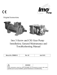
1
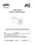
K12DHZ-312P Pump
PRODUCT SERVICE MANUAL
Imo Part Number / BOM # 3220/523
WARNING
This manual and the “General Installation, Operation, Maintenance and
Troubleshooting Manual” (SRM00046) should be read in their entirety prior
to installing, operating or servicing this pump.
Manual No. SRM00102
Rev 00
1
November, 2011
READ ENTIRE PAGE BEFORE PROCEEDING
FOR SAFETY OF PERSONNEL AND TO PREVENT DAMAGE TO EQUIPMENT, THE FOLLOWING
NOMENCLATURE HAS BEEN USED IN THIS MANUAL:
DANGER
Failure to observe precautions noted in this box can result in severe bodily injury or loss of life.
WARNING
Failure to observe precautions noted in this box can cause injury to personnel by accidental contact
with equipment or liquids. Protection should be provided by user to prevent accidental contact.
CAUTION
ATTENTION
Failure to observe precautions noted in this box can cause damage or failure of equipment.
Non compliance of safety Safety instructions where
instructions identified by the electrical safety is involved
following symbol could affect are identified by:
safety for persons:
Safety instructions which shall be
considered for reasons of safe
operation of the pump and/or
protection of the pump itself are
marked by the sign:
ATTENTION
CONTENTS
SAFETY AND TABLE OF CONTENTS ..............................................................................2
A. GENERAL INSTRUCTIONS .......................................................................................3
B. INTRODUCTION..........................................................................................................3
C. DESCRIPTION OF THE PUMP ...................................................................................3
D. PUMP MODEL IDENTIFICATION ...............................................................................4
E. ORDERING INSTRUCTIONS .....................................................................................4
F. OPERATION ...............................................................................................................4
G. PARTS LIST ................................................................................................................6
H. PUMP MAINTENANCE ...............................................................................................7
I. TROUBLESHOOTING ................................................................................................10
J. FIELD AND FACTORY SERVICE AND PARTS ...........................................................10
N. ASSEMBLY DRAWING ...............................................................................................11
O. COLFAX INFORMATION ............................................................................................12
IMPORTANT NOTE
If operation of pump is critical to your business, we strongly recommend keeping a spare pump or major
repair kit in stock at all times. For expeditious pump refurbishment, as a minimum, keep a minor repair kit (orings, gaskets, shaft seal and bearings) in stock.
2
A.
GENERAL INSTRUCTIONS
Instructions found herein cover disassembly, assembly and parts identification for the K12DHZ312P pump.
NOTE: Individual contracts may have specific provisions that vary from this manual. Should
any questions arise which may not be answered by these instructions, refer to General
Instructions Manual, CA-1, provided with your order. For further detailed information
and technical assistance please refer to Imo Pump, Technical/Customer Service
Department, at (704) 289-6511.
This manual cannot possibly cover every situation connected with inspection, and maintenance of
equipment supplied. Every effort was made to prepare text of manual so that engineering and design
data is transformed into most easily understood wording. Imo Pump assumes personnel assigned to
operate and maintain supplied equipment and apply this instruction manual have sufficient technical
knowledge and are experienced to apply sound safety and operational practices which may not be
otherwise covered by this manual.
In applications where equipment furnished by Imo Pump is to become part of processing machinery,
these instructions should be thoroughly reviewed to ensure proper fit of said equipment into overall
plant operational procedures.
WARNING
If installation, operation and maintenance instructions are not correctly and strictly followed and
observed, injury to personnel or serious damage to pump could result. Imo Pump cannot accept
responsibility for unsatisfactory performance or damage resulting from failure to comply with
instructions.
B.
INTRODUCTION
Instruction manual covers the K12DHZ-312P Imo pump. This pump has been designed for use in high
temperature clean fuel oil applications. Model of each pump can be identified by bill of material and
description on pump nameplate.
C.
DESCRIPTION OF EQUIPMENT
The K12DHZ-312P pump is positive displacement, rotary screw pumps consisting of precision bored
housings that enclose a driven screw (power rotor) and eight intermeshing following screws (idler
rotors). These screws, when rotating, form a succession of closures or cavities. As they rotate, fluid is
moved axially from inlet port to outlet port in a continuous, uniform flow with minimum fluid pulsation and
pump noise.
3
D.
PUMP MODEL IDENTIFICATION
This service manual covers the K12DHZ-312P pump. Model of pump is identified on pump nameplate.
Refer to Pump assembly drawing and Table 2 for instructional keys when using this manual.
K
12D
H
Z
312
P
Design Modification
Lead and Rotation
P = 1.6D, CW
Series
1st Letter Designator
(Seal Design)
H- Positive Drive
(Viton O-Ring Fitted,
Hi-Temp Bearing)
Rotor Size
312
2nd Letter Designator
High Pressure Fuel Pump
E.
ORDERING INSTRUCTIONS
When corresponding with Imo Pump regarding K12DHZ-312P pumps, refer to pump nameplate, this
service manual, and assembly drawing as instructed below:
1. From pump nameplate, record the pump model number, serial number and manufactured date.
2. Record service manual number, revision and date.
3. From assembly drawing and/or parts list (table 2) in manual, provide identification numbers(s) and
names for replacement part(s).
4. Give above information to your Imo service representative.
Imo sales and service representatives are listed herein and in General Instruction Manual, SRM00046.
F.
OPERATION
F.1
LIQUID LIMITATIONS
CAUTION
ATTENTION
Never operate with water. Pump is designed for liquids having general characteristics of oil.
4
F.2 OPERATING LIMITS
CAUTION
ATTENTION
Operating conditions, such as speed, fluid viscosity, temperature inlet pressure, discharge
pressure, filtration, duty cycle, drive type, mounting, etc., are interrelated. Due to these
variable conditions, specific application limits may be different from that of operational
limitations. Equipment must not be operated without verifying system’s operating
requirements are within pump’s capabilities.
Under no circumstances are following operating limits (specified in Table 1) to be exceeded without
specific approval from Imo Pump.
Table 1 – Normal Pump Operating and Structural Limits
MAXIMUM SPEED ......................................................................................................2500 RPM
VISCOSITY ........................................................1 cSt Minimum – 3000 SSU (650 cSt) Maximum
MINIMUM – MAXIMUM LIQUID TEMPERATURE .................................0 to 275°F (-18 to 135 C)*
MAXIMUM INLET PRESSURE ........................................................................................ 150 psig
MAXIMUM DISCHARGE PRESSURE .............................................. 2200 psig, Continuous Duty
FILTRATION ......................................................... (See General Instruction Manual, SRM00046)
DRIVE ..............................................................................................................................Direct Only
MOUNTING .................................................................... Foot or Flange Mounted in Any Attitude
* See instructions below for running over 200°F
F3.
High Temperature Operation (Above 200°F (93°C)
For high temperature operation, Imo recommends:
1.
Use a spacer double disk type coupling (Thomas DBZ-C or equivalent) to eliminate need
for hot alignment.
2.
Insulate pump case per Figure 1, except ball bearing area, to keep temperature of all
components approximately the same.
3.
Torque down rear feet of pump per instructions with flat washer and spring washer to allow
foot of case to float as case expands with high temperature. See Figure 2. Front feet
should be torqued to approximately 200 lb-ft with no washer or Loctite required.
5
Figure 1 - RECOMMENDED AREAS FOR PUMP INSULATION
(.188)
([)(4.78)(])
1
SEENOTE2
2
3
(.177)
([)(4.50)(])
REARPUMPFOOT
SHIMS BY
CUSTOMER
.75 [19.1]
MINENGAGEMENT
A
DETAIL A
INSTALL CAPSCREWWITHLOCTITE
THREADLOCKERPRODUCT NO. 271
(PREFERRED), NO. 242 OREQUIVALENT,
PERMANUFACTURER'S INSTRUCTIONS
3/4 HARDENEDCIRCULARWASHER
3/4 REGULARSPRINGLOCKWASHER
STEEL PP002ABH-12
STEEL PP002DA-12
STEEL
Figure 2 – REAR FOOT BOLTING ARRANGEMENT FOR 200 °F AND ABOVE.
6
G. PARTS LIST
Table 2 – Pump Parts List
IDP QTY
1
2
3
4
6
7
8
9
1
1
2
16
1
1
2
1
DESCRIPTION
Case
Inlet Head
Dowel Pin
Case Bolts
Stop Pin
Dyna Seal
Housing Retaining Ring
Inlet O-Ring
KIT
IDP QTY
42
43
46
47
48
49
63
66
67
68
69
70
71
73
79
80
81
91
102
XX
X
XX
X
2
1
1
4
1
1
1
1
2
1
1
1
1
1
1
1
1
16
1
DESCRIPTION
KIT
Bearing Retaining Ring
Bearing Retainer
Inboard Cover
Bearing Retainer Bolts
Seal Seat Adapter
Ball Bearing
Power Rotor
90° Elbow
Pipe Plug
Nipple
Tube Fitting
90° tube to MNPT fitting
Seal Pipe
Suction Housing
Floating BP Bushing
Seal Seat Adapter O-Ring
Cap Screw
Hardened Washers
Orifice Plug
X
21
2 Suction Idler
XX
22
1 Idler Stop
XX
23
2 Thrust Cups
XX
24
1 Discharge Housing
XX
25
1 Seal
X
26
3 Tube
XX
27
4 Tube O-Ring
X
28
2 Housing O-Ring
X
29
1 Thrust Cage
XX
38
1 Seal Spacer
X = Minor Repair Kit Items.
XX = Major Repair Kit Items. (Items marked (X) are included in Major Repair Kit).
H.
X
XX
XX
XX
X
PUMP MAINTENANCE
WARNING
Failure to observe precautions while installing, inspecting and maintaining pump can cause
injury to personnel from accidental handling of liquids that may harm skin or clothing, or fire
hazard risks from flammable liquids, or injury from high pressure fluid jets.
DANGER
BEFORE working on equipment, make sure all power to equipment is disconnected and
locked-out.
H.1 GENERAL COMMENTS
Part number identifiers contained within parenthesis such as (10) refer to circled numbers shown
on assembly drawing, Figure 4 and Table 2.
H.2 TOOLS REQUIRED
Procedures described in this manual require common mechanics hand tools, a torque wrench, dial
indicator and suitable lifting device (such as) slings, straps, etc.
H.3 DISASSEMBLY PROCEDURES
SPECIAL NOTE: To service mechanical seal and ball bearings ONLY perform H.3, Steps 1, 7,
8 and 9 and H.4, Steps 8, 9, 10 and 11 ONLY.
7
WARNING
Fluid leakage from disassembly of pump may make floor slippery and cause personal injury.
1. Close suction and discharge piping to pump and disconnect piping. Remove seal piping (71).
Remove drain plugs (67), and drain unit. Remove pump from driver, coupling and base plate.
Remove coupling hub and key (31).
2. Remove bolts (4) and inlet head (2). Remove O-ring (9) from inlet head (2).
3. Remove spiral rings (8) from grooves in case (1).
4. Remove thrust cage (29), then oil balance tube (26) with O-rings (27) from either cage (29) or
inlet housing (73). Remove O-rings (27) from tube (26).
5. Remove idler cups (23) from suction idlers (21).
6. Remove suction idlers (21) by unscrewing them from inlet end of pump. Remove remaining
idlers (35) from housings (73, 24) by rotating power rotor (63) in a counter-clockwise direction.
ATTENTION
CAUTION
Do not permit idlers (21, 35) to drop as they emerge from housings (73, 24).
7. Remove bolts (47) and bearing retainer (43) from inboard cover (46).
8. Remove assembled power rotor (63). Removal of power rotor (63) includes removal of Truarc
rings (42), ball bearing (49), seal adapter (48), spacer (38) and mechanical seal (25).
Figure 3 – Multi-Spring Seal
9. Disassemble power rotor (63) as follows (See seal insert Figure 3):
a. Using a flat nosed tool, such as a screw driver, remove Truarc rings (42) located on both
sides of ball bearing (49) from their grooves in power rotor (63).
8
b. Sealed ball bearing is assembled to power rotor (63) with a light press fit. Ball bearing (49)
may be removed by using a bearing puller or a vertical arbor press. When using press, two
pieces of key stock are to be placed through openings of mechanical seal seat adapter (48)
underneath ball bearing (49) on both sides of power rotor shaft. Key stock should be long
enough to support power rotor (63) as it is placed in press. Press ram is to be positioned
against power rotor (63) coupling end face. Gently press power rotor (63) through ball
bearing (49). Ensure power rotor (63) does not fall to floor once ball bearing (49) is off of its
diameter.
c. Remove seal seat adapter (48) from power rotor (63), (See seal insert Figure 4) then remove
stationary seat from seal seat adapter (48). Loosen set screws on mechanical seal rotating
assembly body and remove rotating seal seat from power rotor (63). Remove spacer (38)
from the power rotor (63).
10. Remove O-ring (80) from inboard end cover (46).
11. Remove bolts (4) and inboard cover (46) from case (1).
12. Remove O-ring (28) from inboard cover (46).
13. Remove tube (26) from idler stop (22).
14. Remove idler stop (22) from inboard cover (46) by removing bolts (81).
15. Remove floating balance piston (79) from inboard cover (46).
16. Remove stop pin (6) and Dyna seal (7) from case (1).
17. Remove housing (24) from case (1) and O-ring (28) from housing (24).
18. Remove Orifice Plug (102) from discharge housing (24).
ATTENTION
CAUTION
Do not permit housing (24) to drop as it is removed from pump.
19. Remove tube (26) from housing (24 or 73), and O-rings (27) from tube (26).
20. Remove aligning vent pins (3) from housing (24 or 73).
21. Remove housing (73) from case (1).
CAUTION
ATTENTION
Do not permit housing (73) to drop as it is removed from pump.
H.4 PUMP ASSEMBLY PROCEDURE
Note:
Prior to reassembly of pump, all parts should be cleaned and inspected for nicks and
burrs. Replace all worn or damaged parts. Imo Pump recommends replacement of all Orings (9, 27, 28, and 80), Dyna Seal (7), mechanical seal (25) and ball bearing (49) when
these parts are disturbed from their previously installed positions. Coat all parts with light
lubricating oil to assist in assembly.
9
Note:
Bolts (81) have Nylok threads. Torque stated on assembly drawing for bolt (81) does not
include additional torque to install fasteners containing Nylok inserts. Torque required for
first application is much higher than for subsequent applications. To ensure required
preload on Nylok fastener is achieved for each application, the following procedure is
mandatory assembly practice.
1. Using a suitable torque wrench, install fastener in mating piece until Nylok insert is
completely engaged. Note torque required.
2. Add torque measured in step1. to torque value on assembly drawing.
3. Complete tightening fastener to torque value determined in 2.
1. Install O-ring (28) and orifice plug (102) in discharge housing (24).
2. Install discharge housing (24) in pump case (1), from suction end of case, aligning groove in
housing (24) to stop pin hole in case (1). Install stop pin (6) with Dyna Seal (7) in case (1).
3. Install O-rings (27) on oil balance tube (26) and oil balance tube (26) in one end of inlet housing
(73). Install stop pins (3) in same end of inlet housing (73).
4. Install assembled inlet housing (73) in case (1), ensuring that oil balance tube (26) and vent pins
(3) engage holes in discharge housing (24).
5. Install tube (26) in outboard end of discharge housing (24)
6. Install balance piston (79) on inboard cover (46). Install idler stop (22) on inboard cover (46)
with cap screws (81). Torque cap screws to value on assembly drawing. Install O-ring (28) on
inboard cover (46).
7. Install inboard cover (46) on case (1) using bolts (4). Be sure that tube (26) lines up with pin
hole in inboard cover (46). Torque bolts to proper value on assembly drawing.
8. Assemble power rotor (63) and mechanical seal (25) as follows (see seal insert Figure 3 above).
a. Install seat O-ring in groove of mechanical seal (25) stationary seat. Install mechanical
stationary seat in seal seat adapter (48) ensuring that spring pin is properly positioned to
engage slot in seal seat.
b. Install spacer (38) on power rotor (63).
c. Install mechanical seal rotating assembly on power rotor (63) next to spacer (38). Apply
Loctite 242 or equivalent to seal set screws and tighten set screws.
d. Wipe mechanical seal rotating and stationary faces with a clean, lint free cloth before
assembling faces together.
e. Install assembled bearing spacer (48), with stationary seat to power rotor shaft next to
mechanical seal rotating face.
g. Install inner Truarc ring (42) in groove of power rotor (63).
h. Press bearing (49) on power rotor (63), pressing only on inner race of ball bearing (49) until
it is located next to inner Truarc ring (42).
i.
Install outer Truarc ring (42) in groove of power rotor (63).
10
9. Install O-ring (80) in seal bore of inboard cover (46).
10. Install assembled power rotor (63) in pump, centering all parts as they enter inboard cover (46).
Align one of openings in spacer (48) over drain in inboard cover (46).
11. Install bearing retainer (43) on inboard cover (46) using bolts (47). Torque bolts to values
indicated on assembly drawing.
12. Install idlers (35, 21) into housings by meshing threads with power rotor thread and screwing
them into housing idler bores.
13. Install idler balance piston housings (23) to ends of suction idlers (21).
14. Install O-rings (27) on oil balance tube (26) and oil balance tube (26) in inlet housing (73).
15. Install thrust cage (29) to pump case (1), ensuring that pin hole in thrust cage (29) engages tube
(26) in suction housing (73).
16. Install retaining rings (8) to pump case (1).
17. Install O-ring (9) to groove in inlet head (2).
18. Install inlet head (2) using bolts (4). Torque bolts to values indicated on assembly drawing.
19. Install seal piping (71) and drain plug (67).
Note: Inlet head (2) can be rotated and repositioned in 90° increments to suit suction piping. To
change inlet position, disconnect seal piping (71), remove bolts (4) and rotate inlet head
to desired position. Install bolts (4) and torque to proper values indicated on assembly
drawing. Reconnect seal piping (71).
20. Install coupling hub key (31). Install and align pump and driver as specified in General
Instruction Manual, SRM00046 or if CE compliance is required, see “CE - Installation,
Maintenance & Troubleshooting Manual“, SRM00101.
.5 SPECIAL TESTING INSTRUCTIONS
After pump has been reassembled with a major kit, it is recommended that a break-in test be
performed to allow idlers to polish into babbitted housing bores. For this test, pump should be run to
maximum required working pressure starting from 300 psig, in 200 psig increments, holding each
pressure for five minutes.
I.
TROUBLESHOOTING
For assistance with troubleshooting see “General Installation, Operation, Maintenance and
Troubleshooting” Manual, SRM00046 or if CE compliance is required, see “CE - Installation, Maintenance
& Troubleshooting Manual“, SRM00101.
J. FIELD AND FACTORY SERVICE AND PARTS
Imo Pump maintains a staff of trained service personnel that can provide pump installation, pump startup, maintenance/overhaul and troubleshooting supervision as well as installation and maintenance
training.
11
Our factories provide maintenance, overhaul and test facilities in event user prefers to return pumps for
inspection or overhaul. Pumps that have been factory-overhauled are normally tested and warranted “asnew” for a period of one year from date of shipment. For either field service or factory overhaul
assistance, contact your local Imo Sales Office or representative at Technical/Customer Service
Department in Monroe, NC, USA.
Most pumps have repair kits available. Minor Repair Kits are used to repair leaking seals, bad bearings
and/or for re-assembly after pump tear-down. They include (as applicable) pump shaft seals, packing, all
gaskets/O-rings and bearings. Major Repair Kits are sufficient to rebuild completely worn-out pumps to
“as-new” condition. They include all parts found in Minor Repair Kits plus all major internal parts subject
to wear. Since kits have all necessary parts, it is preferred that they be purchased rather than selecting
individual parts. When parts are individually selected from Parts List, some needed components are
often overlooked. In addition, mixing worn or used parts with new parts risks rapid wear and shortened
service life from new parts.
12
A Colfax Business Unit
IMO Pump
1710 Airport Road 28110
PO Box 5020
Monroe, NC/USA 28111-5020
TEL:
Email:
Web:
13
1+ (704)289-6511
[email protected]
www.imo-pump.com