1
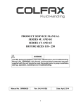
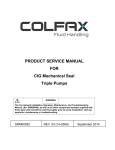
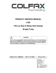
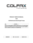
PRODUCT SERVICE MANUAL
SERIES 110H & 210H
WARNING
The IMO General Installation Operation, Maintenance and Troubleshooting Manual,
(No. SRM00046), this manual, and associated component manuals supplied with the
unit should be read thoroughly prior to pump installation, start-up, operation,
maintenance or troubleshooting.
Manual No. SRM00011
Rev. 5 (14-0144)
Date: March 2014
READ THIS ENTIRE PAGE BEFORE PROCEEDING
FOR THE SAFETY OF PERSONNEL AND TO PREVENT DAMAGE TO THE EQUIPMENT, THE
FOLLOWING NOMENCLATURE HAS BEEN USED IN THIS MANUAL:
DANGER
Failure to observe the precautions noted in this box can result in severe bodily injury
or loss of life.
WARNING
Failure to observe the precautions noted in this box can cause injury to personnel
by accidental contact with the equipment or liquids. Protection should be provided
by the user to prevent accidental contact.
CAUTION
ATTENTION
Failure to observe the precautions noted in this box can cause damage or failure
of the equipment.
Non-compliance of safety
instructions identified by
the following symbol could
affect safety for persons:
Safety instructions where
electrical safety is involved
are identified by:
Safety instructions which
shall be considered for
reasons of safe operation of
the pump and/or protection of
the pump itself are marked
by the sign:
ATTENTION
ATTENTION
If operation of this pump is critical to your business, we strongly recommend you keep
a spare pump or major repair kit in stock at all times. As a minimum, a minor repair
kit (O-rings, gaskets, shaft seal and bearings) should be kept in stock so pump
refurbishment after internal inspection can be accomplished.
CONTENTS
Safety and Table of Contents ...................................................................................... Inside Cover
General Instructions ..................................................................................................................... 1
Ordering Instructions..................................................................................................................... 1
Introduction ................................................................................................................................... 1
Special Installation Instructions ..................................................................................................... 2
Description of the Equipment ........................................................................................................ 2
Assembly and Disassembly Instructions ....................................................................................... 3
Parts List and Pump Assembly Drawing ....................................................................................... 4
Disassembly of Mechanical Shaft Seal ......................................................................................... 5
Installation of Mechanical Shaft Seal ............................................................................................ 6
GENERAL INSTRUCTIONS
The instructions found herein cover the disassembly, assembly and parts identification of Series 110H and
210H pumps.
NOTE: Individual contracts may have specific provision that vary from this manual. Should any questions
arise which may not be answered by these instructions, refer to the General Instructions Manual,
CA-1, provided with your order. For further detailed information and technical assistance please
refer to Imo Pump, Technical Service Department at (704) 289-6511.
This manual cannot possibly cover every situation connected with the installation, operation, inspection and
maintenance of the equipment supplied. Every effort was made to prepare the text of the manual so that
engineering and design data is transformed into the most easily understood wording. Imo Pump must
assume the personnel assigned to operate and maintain the supplied equipment and apply this instruction
manual have sufficient technical knowledge and are experienced to apply sound safety and operational
practices which may not be otherwise covered by this manual.
ORDERING INSTRUCTIONS
All correspondence pertaining to renewal parts for the equipment must refer to the instruction manual number
and should be addressed to the nearest Imo representative. The handling of renewal orders will be greatly
facilitated if the following directions are carefully observed:
1. Give the number of the instruction manual.
2. Give the model number of the pump for which the part is desired. This number appears on the nameplate.
3. Designate the desired part by the IDP number and name as listed in Table 1 and pump assembly drawing
in this instruction manual.
INTRODUCTION
This manual covers all basic models of the 110H and 210H series Imo pumps. The model of a particular pump
may be found on the nameplate. Definitions of model designators are given in Figure 1.
110H
XXX
XX
Rotation
“Blank” – Clockwise
“LH” – Counterclockwise
Design Revision
Series
Rotor Size
“87” “106”
“95” “118”
Rotor Lead
“2D”, “1.6D”
Figure 1 – Definition of Model Designators
1
SPECIAL INSTALLATION INSTRUCTIONS
1. Driver – The Series 110H and 210H may be mounted in any position without affecting the operation of
the pump. Of all the positions, the least desirable position for applications involving cyclic duty, is with the
pump mounted with the shaft down in a vertical position, that is with the pump above the motor. It is
recommended that the unit be driven directly through a flexible coupling.
2. Inlet Position – The inlet flange may be positioned in increments of 90° from the position shown on the
assembly drawing. To change the position of the inlet flange, remove the socket head cap screws (6)
and lock washers (7). Rotate the housing (1) and the inlet head (2) as a unit taking care not to damage
o-ring (9). Install the socket head cap screws with their lock washers and torque per pump assembly
drawing, page 5.
3. Suction Strainer – A suction strainer of at least 100 mesh with a flow capacity of 30-50 gpm and a
pressure drop not exceeding 0.5 psi (when newly installed) should be used. (The inlet strainer shall be
sized to insure that the pressure at the inlet port of the pump will not, under any circumstances, exceed 10
inches of mercury vacuum). Maintenance instructions shall provide for the periodic cleaning or
replacement of the inlet strainer.
DESCRIPTION OF EQUIPMENT
CAUTION
Operating conditions, such as speed, fluid viscosity, temperature inlet pressure, discharge
pressure, filtration, duty cycle, drive type, mounting, etc. are interrelated. Due to these variable
conditions, the specific application limits may be different from that of the operational
limitations. This equipment must not be operated without verification that operating
requirements are within its capabilities.
OPERATING TEMPERATURE AND THERMAL SHOCK EXPOSURE
Never operate with water. The pump is designed for liquids having the general characteristics of oil.
Under NO circumstances are the following operating limitations to be exceeded:
Operating Pressure: 1200 PSIG max. continuous for model 110H with lube and hydraulic oils.
1500 PSIG max. continuous for model 210H with lube and hydraulic oils.
Up to 2000 PSIG under approved conditions. Consult Imo.
Inlet Pressure:
35 PSIG maximum
Temperature:
180°F, assuming fluid viscosity is within allowed limits.
CAUTION
Never exceed the equipment’s minimum or maximum allowable fluid temperature. Do not
expose equipment to thermal shock. Differences in metallurgy and their respective coefficients
of expansion could cause distortion of pump parts resulting in a breakdown condition.
2
ASSEMBLY AND DISASSEMBLY PROCEDURES
Note: Refer to part numbers as shown on the pump assembly drawing and the IDP numbers in
Table 1.
WARNING
Before starting any maintenance procedure:
•
•
Remove electrical service fuse, de-energize and lock the electrical service panel supply
to the driver.
Shut, wire or chain shut and lock all pump piping valves. If applicable, shut off any steam
supply lines to the pump and/or driver.
If seal only is to be serviced, follow the disassembly and reassembly procedures on pages 4 and 5.
If complete overhaul of pump is required, removal of pump from its mounting and locating the pump in a
suitable work area is recommended. It is also recommended that all gaskets and the seal be replaced during
overhaul; regardless of their condition.
PUMP DISASSEMBLY
1. Remove pump from the bracket.
2. Remove the four cap screws (6) and lock washers (7) and remove the inlet head (2).
3. Remove the idler rotors (14) with their thrust shoes (15) by screwing them out of the rotor housing (1).
4. Remove rotor housing (1) with o-rings (9). Do not remove pin (21).
5. Remove four cap screws (23) and ball bearing retainer (22).
6. Remove power rotor assembly from outlet head (4).
Note:
Special detailed disassembly procedure for the removal of the ball bearing and seal are
provided on page 4.
PUMP ASSEMBLY
Note: Clean and inspect all parts before assembly. Replace all worn or damaged parts. It is recommended that gaskets and mechanical seal be replaced regardless of their condition. Wipe each part
with light lubricating oil just before installing. Rotate power rotor (34) frequently during assembly to
ensure freedom of rotation.
1. Clean all parts prior to assembly.
2. Install power rotor assembly in outlet head (4).
Note: Special detailed instructions for power rotor assembly are given on page 5.
3. Install ball bearing retainer (22) and four cap screws (23). Torque cap screws uniformly per drawing on
page 4.
3
4. Lubricate the housing pilots with a light oil or hydraulic fluid and install new O-rings (9) against shoulder of
housing (1).
5. Lubricate the thread section of the power rotor (11) and install housing on outlet head (4).
6. Lubricate idler rotors (13) with light oil or hydraulic fluid and screw into housing.
7. Install inlet head (2) with capscrews (6) and lock washers (7) per drawing on page 3. Turn power rotor by
hand. Rotor should turn freely.
8. Install key (19) in rotor keyway. Make sure that the key does not overhang the end of the shaft.
9. Align pump to bracket and install pump mounting bolts.
IDP
1
2
4
5
6
7
8
9 X
Description
IDP
Rotor Housing
Inlet Head
Outlet Head
Balance Piston Bushing
Cap Screw (4)
Lock Washer (4)
Plug
O-Ring (2)
Description
10*
13
23
16 X
17 X
19
20 X
21
Power Rotor Sub-Assembly*
Idler Rotor Sub-Assembly** (2)
Retainer
Ball Bearing
Snap Ring (2)
Coupling Key
Seal
Pin
*Piece (10) consists of parts (11) and (12). These parts are factory mounted and not serviced separately.
Recommended Spare Parts:
All parts marked X make up a minor repair kit. Other parts cannot be serviced.
All quantities are one except when noted in Parentheses.
Table 1 – List of Material
2
CHECK VALVE
SUPPLIED ON
D210H PUMP
DESIGN ONLY
21
4
1
20
16
22
17
19
Capscrew Torque, Item (6)
110H Series
10 ± 2 FT. LBS.
210H Series
40 ± 5 FT. LBS.
Capscrew Torque, Item (23)
110H and 210H Series 25 ± 5 IN. LBS.
6
7
(15)
13
9
(11)
10
(14)
13
9
5
(12)
10
20
23
Pump Assembly Drawing
4
DISASSEMBLY OF MECHANICAL SHAFT SEAL
1. Remove four cap screws (23) and ball bearing retainer (22). Pull power rotor from outlet cover of pump.
2. After removing coupling hub from rotor, remove outer snap ring (17) from power rotor as shown in Figure 1.
3. Insert rotor assembly in press as shown in Figure 2, and gently press to move bearing approximately oneeighth (1/8") inch. Do not try to press bearing completely off because another snap ring (17) between seal
seat and bearing limits seal seat movement.
4. Separate bearing and seal seat as shown in Figure 3. Insert two pieces of key stock between ball bearing
and seal seat. Continue to press bearing from shaft. Discard bearing.
5. Remove snap ring (17) using standard external snap ring pliers (Figure 4). Hold seal seat during this
operation to prevent spring force from pushing seal assembly apart.
Note: Seal bellows will normally be bonded to shaft.
6. Remove seal seat. Remove seal subassembly as shown in Figure 5 and inspect the shaft. If shaft is pitted
or badly scratched or snap ring grooves are damaged, the rotor subassembly (10) must be replaced.
7. Clean shaft and snap ring grooves prior to installing new seal and bearing. Do not use old seal or bearing.
KEY
STOCK
FIGURE 3
FIGURE 1
FIGURE 2
FIGURE 5
FIGURE 4
5
INSTALLATION OF MECHANICAL SHAFT SEAL TYPE 110H & 210H HYDRAULIC PUMP
1. To install the mechanical shaft seal, clean the shaft with solvent to remove dirt and grease. Lubricate shaft with clean
light lubrication oil (DO NOT USE GREASE).
2. After placing spring holder and spring on shaft, grasp seal subassembly as shown in Figure 1, and using a rotating
motion, gently slide the seal subassembly on the shaft. Use care not to cut the flexible Bellows. See seal
subassembly Figure 6 showing seal seat retainer, carbon ring flexible diaphragm and drive ring. Clean seal faces
with alcohol and apply a light coat of clean oil.
3. Slide seal seat over shaft and compress seal assembly against power rotor balance piston to expose snap ring
groove.
4. Using standard external snap ring pliers, install snap ring (17) as shown in Figure 2. Properly seated snap ring is as
shown in Figure 3.
5. Place ball bearing (16) on shaft. Then using a hollow tube and pressing on the inner race, seat the bearing firmly
against the snap ring as shown in Figure 4.
6. Check mechanical seal – referring to Figure 6, the flexible Bellows must show evenly out of the drive ring. The drive
lugs on the retainer must engage the drive ring to their full strength. Make sure seal bellows is not covering the
drilled seal return hole in the power rotor.
7. Install outer snap ring (17), Figure 5.
8. Lightly oil rotor threads and install rotor assembly into outlet cover.
FIGURE 1
FIGURE 3
FIGURE 2
Washer
Drive
Vents
Retainer
Spring
"O" Ring
BEARING
TOOL
Drive
Ring
Notches
Seat
Rotating
Carbon
Ring
Flexible
Bellows
Drive
Ring
FIGURE 6
FIGURE 4
FIGURE 5
6
IMO Pump
1710 Airport Road -28110
PO Box 5020
Monroe, NC/USA 28111-5020
Tel: 1+(704) 289-6511
+1.877.853.7867
Fax: 1+(704) 289-9273
Email: [email protected]
Web: www.imo-pump.com
© 2012 Colfax Fluid Handling all rights reserved.
6