1
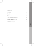
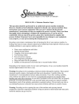
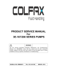
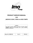
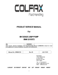
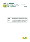
PRODUCT SERVICE MANUAL
SERIES 4U AND 6U
SERIES 4T AND 6T
ROTOR SIZES 118 - 250
WARNING
The IMO General Installation Operation, Maintenance and Troubleshooting
Manual, (No. SRM00046), this manual, and associated component manuals
supplied with the unit should be read thoroughly prior to pump installation,
start-up, operation, maintenance or troubleshooting.
Manual No. SRM00026
Rev. 04 (14-0159)
1
Date: April, 2014
READ THIS ENTIRE PAGE BEFORE PROCEEDING
FOR SAFETY OF PERSONNEL AND TO PREVENT DAMAGE TO EQUIPMENT, FOLLOWING
NOMENCLATURE HAS BEEN USED IN THIS MANUAL:
DANGER
Failure to observe precautions noted in this box can result in severe bodily injury or loss of life.
WARNING
Failure to observe precautions noted in this box can cause injury to personnel by accidental
contact with equipment or liquids. Protection should be provided by user to prevent accidental
contact.
CAUTION
ATTENTION
Failure to observe precautions noted in this box can cause damage or failure of equipment.
Noncompliance of safety
instructions identified by the
following symbol could affect
safety for persons:
Safety instructions where
electrical safety is involved
are identified by:
Safety instructions which
shall be considered for
reasons of safe operation of
pump and/or protection of
pump itself are marked by
sign:
ATTENTION
ATTENTION
If operation of this pump is critical to your business, we strongly recommend you keep a spare
pump or major repair kit in stock at all times. As a minimum, a minor repair kit (o-rings,
gaskets, shaft seal and bearings) should be kept in stock so pump refurbishment after internal
inspection can be accomplished.
Table of Contents
A. GENERAL INSTRUCTIONS ................................................................................................................................................. 3
B. INTRODUCTION ............................................................................................................................................................... 3
C. DESCRIPTION OF EQUIPMENT ......................................................................................................................................... 3
D. PUMP MODEL IDENTIFICATION....................................................................................................................................... 4
E. ORDERING INSTRUCTIONS .............................................................................................................................................. 4
F. OPERATION...................................................................................................................................................................... 5
F.1 LIQUID LIMITATIONS ...................................................................................................................................................... 5
F.2 OPERATING LIMITS ......................................................................................................................................................... 5
G. PART LIST ......................................................................................................................................................................... 6
H. MAINTENANCE ................................................................................................................................................................ 6
H.1 GENERAL COMMENTS ................................................................................................................................................... 6
H.2 TOOLS REQUIRED .......................................................................................................................................................... 7
H.3 PUMP DISASSEMBLY...................................................................................................................................................... 7
H.4 PUMP ASSEMBLY ............................................................................................................................................................ 8
ASSEMBLY DRAWINGS ..........................................................................................................................................................11
2
A. GENERAL INSTRUCTIONS
This manual cannot possibly cover every situation connected with installation, operation, inspection, and
maintenance of equipment supplied. Every effort was made to prepare text of manual so that
engineering and design data is transformed into the most easily understood wording. Imo Pump must
assume personnel assigned to operate and maintain supplied equipment and apply this instruction
manual have sufficient technical knowledge and are experienced to apply sound safety and operational
practices which may not be otherwise covered by this manual.
WARNING
If installation, operation, and maintenance instructions are not correctly and strictly followed and
observed, injury to personnel or serious damage to pump could result. Imo Pump cannot accept
responsibility for unsatisfactory performance or damage resulting from failure to comply with
instructions.
B. INTRODUCTION
This instruction manual covers IMO Pump Division Series 4U and 6U and Series 4T and 6T pumps.
These two series of IMO pumps have been designed to meet requirements of hydraulic industry in
medium flow ranges. Because of large number of operating conditions, it is necessary to have a
variety of construction and material combinations to meet job requirements. Model of each pump is
identified on pump nameplate. Specific models discussed in this manual are identified in Table I
below by Figure Numbers only. Correct use of this manual requires proper identification of Figure(s)
applicable to pump assembly and seal arrangement. Refer to assembly drawings, Figures 7 through
15, for pump identification and mechanical seal drawings, Figures 3 through 6 for applicable seal
selection. Model designators are identified in Figures 1 and 2.
Table 1
Series 4U, 6U, 4T, and 6T Pumps
Pump
Model
Rotor
Size
Pump
Fig. No.
Seal Fig.
No.
Pump
Model
Rotor
Size
Pump
Fig. No.
Seal
Fig. No.
4UVC
6UVC
4UVF
6UVF
4UVC
6UVC
4UVF
6UVF
6UKC
4TVFCS
6TVFCS
4TVTFCS
6TVTFCS
137-200
118-200
137-200
118-200
218-250
218-250
218-250
218-250
156
137-200
137-200
137-200
137-200
7
7
8
8
9
9
10
10
11
12
12
12
12
3
3
3
3
3
3
3
3
4TVFCS
6TVFCS
4TVTFCS
6TVTFCS
4TXS
6TXS
4TXS
6TXS
4TXS
6TXS
218-250
218-250
218-250
218-250
137-156
137-156
187-200
187-200
218-250
218-250
14
14
14
14
12
12
12/13
12/13
14
14
3
3
3
3
4
4
5
5
6
6
187
187
15
15
3
3
3
3
4TXCFS
6TXCFS
C. DESCRIPTION OF EQUIPMENT
Series 4U and 6U and Series 4T and 6T pumps are positive displacement, rotary screw pumps
consisting of a precision bored housing which encloses a driven screw (power rotor) and two
intermeshing following screws (idler rotors). These screws when rotating form a succession of closures
or cavities. As they rotate, fluid is moved axially from inlet port to outlet port in a continuous, uniform
flow with minimum fluid pulsation and pump noise.
3
D. PUMP MODEL IDENTIFICATION
FIGURE 1. DEFINITIONS OF MODEL DESIGNATORS FOR SERIES 4U AND 6U
FIGURE 2. DEFINITIONS OF MODEL DESIGNATORS FOR SERIES 4T AND 6T
E. ORDERING INSTRUCTIONS
When corresponding with Imo Pump regarding Series 4U and 6U and Series 4T and 6T pumps, refer
to pump nameplate, this instruction manual, and assembly drawing as instructed below:
• From pump name plate, record pump model number, serial number, and manufactured date.
• Record instruction manual number, revision, and date.
• From instruction manual, record figure numbers that apply to replacement part(s).
• From assembly drawing or parts list (Table 3) provide IDP number(s) and names for replacement
part(s).
• Give above information to you Imo service representative.
Imo sales and service representatives are listed herein and in the General Instruction Manual,
SRM00046.
4
F. OPERATION
F.1 LIQUID LIMITATIONS
Never operate with thin liquids suck as solvents or water. Pump is designed for liquids having
general characteristics of oil.
F.2 OPERATING LIMITS
CAUTION
ATTENTION
Operating conditions, such as speed, fluid viscosity, temperature, inlet pressure, discharge
pressure, filtration, duty cycle, drive type, mounting, etc., are interrelated. Due to these variable
conditions, specific application limits may be different from operational limitations. Equipment
must not be operated without verifying system operation requirements are within pump’s
capabilities.
Under no circumstances should following operating limits specified in table 2 be exceeded
without specific approval from Imo Pump.
MAXIMUM SPEED
ROTOR SIZE
MAXIMUM RPM
118
5400
137-156
4400
187-250
3600
Contact IMO Pump Division for Performance Tables
VISCOSITY
4U AND 6U
4T AND 6T
MINIMUM:
33 SSU
33 SSU
MAXIMUM:
3000 SSU
3000 SSU
Contact IMO Pump Division for minimum allowable operating viscosity at specific speeds and pressure
TEMPERATURE
0 - 160° F
PRESSURE
MAXIMUM
SUCTION
MAXIMUM
DRIVE
FILTRATION
4U AND 4T
6U AND 6T
1500 PSIG
2500 PSIG
Contact IMO Pump Division for Performance Tables
4U AND 6U
4T AND 6T
50 PSIG
100 PSIG
*Discharge pressure must always be 50 PSIG above suction pressure*
Direct Only
60 Mesh minimum recommended
Table 2 – Normal Pump Operating and Structural Limits
SPECIAL NOTE
Series 4U and 6U and Series 4T and 6T units can be operated as hydraulic motors by reversing the rotation
of the unit when used as a pump. High pressure inlet of motor is the same as high pressure outlet of the
pump. Low pressure outlet of the motor is the same as low pressure inlet of the pump. When ordering
replacement parts for units used as motors, refer to List of Materials, Table 3, keeping in mind that parts
listed are for pump units. Example (001) Outlet Cover is Inlet Cover for unit used as a hydraulic motor.
5
G. PART LIST
lDP NO.
PART DESCRIPTION
lDP NO.
001
002
003 (3)
004
006 (1)(4)
007 (2)
008
009
010 (2)
011 (2)
014 (2)
015 (2)
Cover
Inlet Head
Capscrew (6)
Nut (6)
Gasket
Balance Piston Bushing
Retainer
Bolt (4)
Power Rotor
Idler (2)
Stop
Housing Sub-Assembly
019 (2)
PART DESCRIPTION
lDP NO.
Spacer Sub-Assembly
046
047
048
049
050 (1)
051
052
053
054 (1)
055
056
057 (1)
058
059
060
061
062
(Includes Items 059 and 060)
020 (1)
021 (1)
022
027 (2)
028 (2)
031
032
035 (1)
036 (2)
041
(Includes item 042 and 058) 042
0-ring
043
016 (1)
Capscrew
(12)
Seal
044 (2)
017 (5)(2)
045
018 (1)
Ball Bearing
Truarc Ring (2)
Key
Capscrew (2)
Plate
Nameplate
Drive Screw (2)
Back-Up Ring
Clamp Ring
Spacer (2)
Spring Pin
Spacer
Capscrew (2)
Nameplate
PART DESCRIPTION
Tube
Drive Screw (3)
Plug
Connector
0-ring
Capscrew (4)
Lockwasher (4)
Connector
0-ring
Capscrew (4)
Lockwasher (4)
Gasket
Housing
Spacer
Spring Pin
0-ring
Sleeve
Quantities are one (1) except when noted in parentheses after part description.
(1) Minor Repair Kit items.
(2) Major Repair Kit items.
(Items marked (1) are included in
Major Repair Kit.)
(3) Quantity twelve (12) for Figures 12,
14 and 15.
(4) Part description 0-ring for Figures
12, 14 and 15.
(5) Quantity sixteen (16) for Figures 12,
14 and 15.
H. MAINTENANCE
DANGER
BEFORE working on equipment, make sure all power to equipment is disconnected and locked-out.
WARNING
Failure to observe precautions while installing, inspecting and maintaining pump can cause injury
to personnel form accidental handling of liquids that may harm skin or clothing, or fire hazard risks
from flammable liquids, or injury from high pressure fluid jets.
H.1 GENERAL COMMENTS
Note: Part number identifiers (IDP) contained with parenthesis, such as (9), refer to numbers on
assembly drawings.
*De-energize driver before starting with any maintenance action.*
H.2 TOOLS REQUIRED
Procedures described in this manual require common mechanics hand tools, a torque wrench, dial
indicators for alignment and a suitable lifting device such as slings, straps, etc.
6
Figure 3. Mechanical Seal Drawing (Single Spring, Bellows Type)
*4T, 6T – O-ring Type ; 4U, 6U – “J” Type*
Figure 4. O-Ring Type Seal Seat Adapter
Figure 5. J Seat Seal Spacer
H.3 PUMP DISASSEMBLY
Determine pump model identification on pump nameplate to select applicable pump assembly. Refer
to that assembly for the following instructions.
CAUTION
ATTENTION
Fluid leakage from disassembly of pump may make floor slippery and cause personal injury.
1. Close off suction and discharge piping to pump and disconnect piping. Remove pump from driver,
coupling and mounting bracket. Remove coupling hub and key (022).
2. Remove nuts (004), capscrews (003), and inlet head (002). Remove gasket (006, Figures 7, 8, 9, 10,
and 11) or 0-ring (006, Figures 12, 14 and 15) from cover (001).
3. Remove capscrews (027), plate (028) and spacers (041).
4. Remove idler rotors (011) by unscrewing idler rotors from housing bores.
CAUTION
ATTENTION
Do not permit idlers (011) to drop as they emerge from housing (015).
7
5. Remove bolts (009) and bearing retainer (008).
6. Slide assembled power rotor (010) from pump. Removal of assembled power rotor includes:
(Figures 7, 8, 9, 10, 12, 13 and 14)- Truarc rings (021), ball bearing (020), spacer (019), mechanical
seal (018) and spacer (062, Figure 13 only). (Figures 11 and 15)- Truarc rings (02I) and ball bearing
(020).
7. Remove inboard truarc ring (referencing the pump shaft/keyway as inboard side) from power rotor
(010).
8. Using an arbor press, press bearing ½” off shaft in order to access outboard truarc ring (021).
9. Remove outboard truarc ring (021).
10. Using an arbor press, remove bearing from power rotor.
11. Remove seal seat adapter and O-ring (gasket)/spacer, “J” seat, and gasket from power rotor.
12. Slide rotating assembly off the power rotor (assembly consist of spring holder, spring, bellows, drive
band, and rotating ring)
13. (Figure 11 Only) Remove spacers (019, 018 and 046) from cover (001).
14. (Figure 15 Only) Remove spacer (019) and gasket (057) from cover (001).
15. Remove gasket or O-ring from mechanical seal bore of cover (001).
(Figures 7, 8, 9 and 10) - Gasket furnished with mechanical seal (018).
(Figures 12, 13 and 14)- Gasket (057, Figures 12 and 14), O-ring (061, Figure 13).
16. Remove capscrews (017) and slide housing (015) from outlet end of cover (001). Removal of housing
(015) also removes clamp rings (036), spring pin (042), 0-ring (016) and backup ring (035). Remove 0ring (016), backup ring (035) and clamp rings (036) from housing (015).
17. Remove capscrews (044) and idler stop (014).
18. (Figures 7, 8, II, 12, and 15) Slide spacer (043) from cover (001).
19. Remove bushing (007) from cover (001).
H.4 PUMP ASSEMBLY
Prior to assembly of pump, all parts should be cleaned and inspected for nicks and burrs. Replace all
worn or damaged parts. Colfax recommends replacing all O-rings, gaskets, mechanical seals and
ball bearings when these parts are disturbed from their previously installed positions. Refer to proper
assembly drawings, Figures 7 through 15, mechanical seal drawing, List of Materials, Table 3, during
assembly. Coat all parts with light lubricating oil to assist in assembly.
NOTE: Unless noted, assembly procedures apply to all pumps, Figures 7 through 15.
1. Install bushing (007) in cover (001).
2. (Figures 7, 8, 11, 12 and 15) Install spacer (043) in cover (001).
3. Install idler stop (014) to cover (001) using capscrews (044). Torque capscrews (044) to 10 lbs. ft. (± 2
lbs. ft.).
4. Insert 0-ring (016) and backup ring (035) into groove of housing (015).
8
NOTE: Backup ring (035) must be positioned on side of groove toward clamp ring (036) slot.
5. Install rotor housing (015) in cover (001).
NOTE: Do not insert housing (015) past clamp ring grooves.
6. Install clamp rings (036) in grooves of housing (015).
NOTE: Clamp ring (036) with slot on inside diameter fits over spring pin (042) in housing (015).
7. Install capscrews (017) in clamp rings (036) and torque capscrews (017) to proper value shown in
Table 2.
8. (Figure 11 Only) Install spacers (046, 018 and 019) in cover (001).
9. (Figure 15 Only) Install gasket (057) and spacer (019) in cover (001).
CAUTION
ATTENTION
Coat all parts of mechanical seal with oil prior to assembly on power rotor.
NOTE: Rotating Assembly: The rotating assembly is normally packaged as an assembly for ease of
installation. Ensure that all O-rings are properly positioned in assembly prior to installation.
*Assemble the mechanical seal/ bearing assembly onto the power rotor (Steps 10-15)*
10. Slide rotating assembly onto power rotor with rotating assembly positioned next to stepcut shoulder of
power rotor.
11. (O-ring type)-Install stationary seal seat into seal seat adapter, ensuring that slot in seal face is aligned
with roll pin. (“J” type/O-ring type)- Install gasket/O-ring (see drawings for correct IDP number) furnished
with mechanical seal on cover (001).
12. Install seal seat adapter/ “J” seat and spacer onto power rotor.
13. Install truarc rings on outboard groove of power rotor.
14. Using an arbor press, press bearing until inner race of bearing makes contact with truarc rings. Install
truarc rings in inboard groove of power rotor. This secures bearing inner race into position. (optional)
Heat bearing, using a bearing heater/induction heater, to 200° F and slide bearing into position.
Mechanical seal must then be manual compressed to install inboard truarc ring.
15. Slide assembled power rotor (010) into outlet cover (001) ensuring that all parts are properly positioned.
16. Install bearing retainer (008) to cover (001) using bolts (009). Torque bolts (009) to 25 lbs. ft. (± 2lbs. ft.).
17. Insert idlers (011) by screwing them into rotor housing (015) bores.
18. Install spacers (041) and plate (028) using capscrews. Torque capscrews (027) to proper value listed in
Table 3.
19. (Figures 12, 14 and 15) Install 0-ring (006) in groove of cover (001).
20. (Figures 7, 8, 9, 10 and 11) Install gasket (006) on cover (001).
9
21. Install inlet head (002) using capscrews (003) with nuts (004). Torque capscrews (003) to necessary
value listed in Table 3.
22. Mount pump to bracket. Install key (022) and coupling hub. Connect driver and piping.
NOTE: (Figures 12, 14 and 15) If inlet and outlet connectors were removed from pump, O-rings
should be replaced during re-assembly.
TABLE 3 – TORQUE VALUES
Part
Capscrew
(003)
Capscrew
(017)
Capscrew
(027)
Rotor Size
Torque Values
Special Instructions
118
137-156
187-200
218-250 (U)
218-250 (T)
118
137-156
187-200
218-250
118
137-156
187-200
218-250
50 lbs. ft. (+ 2 lbs. ft.)
52 lbs. ft. (+ 2 lbs. ft.)
52 lbs. ft. (+ 2 lbs. ft.)
100 lbs. ft. (+ 2 lbs. ft.)
75 lbs. ft. (+ 2 lbs. ft.)
80 lbs. ft. (+ 5 lbs. ft.)
80 lbs. ft. (+ 5 lbs. ft.)
110 lbs. ft. (+ 5 lbs. ft.)
300 lbs. ft. (+ 10 lbs. ft.)
25 lbs. ft. (+ 2 lbs. ft.)
40 lbs. ft. (+ 2 lbs. ft.)
80 lbs. ft. (+ 2 lbs. ft.)
150 lbs. ft. (+ 2 lbs. ft.)
NOTE: Inlet head (002) can be rotated to suit suction pipe
arrangements as follows:
4U and 6U, Rotor Sizes 118 through 156 - 60° increments
4U and 6U, Rotor Sizes 187 through 250 - 45° increments
4T and 6T - 90° increments
*Remove capscrews (003) with nuts (004) and rotate inlet
head (002). Ensure that gasket (006) or 0-ring (006)
between inlet head and cover (001) is not damaged. If
gasket or 0-ring is damaged, it must be replaced to
prevent air leakage. When replacing capscrews (003),
torque capscrews to value given in Table 3.*
I. TROUBLESHOOTING
For assistance with troubleshooting see General Instruction Manual, SRM00046.
J. FIELD AND FACTORY SERVICE AND PARTS
Imo Pump maintains a staff of trained service personnel that can provide pump installation, pump startup,
maintenance/overhaul and troubleshooting supervision as well as installation and maintenance training.
Our factories provide maintenance as well as overhaul and test facilities in event user prefers to return
pumps for inspection or overhaul. Factory-overhauled pumps are normally tested and war anted “as-new”
for a period of one year from date of shipment. For either field service or factory overhaul assistance,
contact your local Imo Sales Office or representatives at Technical/Customer Service Department in
Monroe, NC, USA.
Most pumps have repair kits available Minor Repair Kits are used to repair leaking seals, bad bearings
and/or for re-assembly after pump tear-down. They include (as applicable) pump shaft seals, packing, all
gaskets/O-rings and bearings. Major Repair Kits are sufficient to rebuild completely worn-out pumps to
“as-new” condition. They include all parts found in the Minor Repair Kits plus all major internal parts
subject to wear. Since kits have all necessary parts, kit purchase is preferred rather than selecting
individual parts. When parts are individually selected from Parts List, some needed components are often
overlooked. In addition, mixing worn or used parts with new parts risks rapid wear and shortened service
life from new parts.
10
11
FIGURE 9.
12
13
FIGURE 12.
FIGURE 13.
14
FIGURE 14.
15
IMO Pump
1710 Airport Road -28110
PO Box 5020
Monroe, NC/USA 28111-5020
Tel: 1+(704) 289-6511
+1.877.853.7867
Fax: 1+(704) 289-9273
Email: [email protected]
Web: www.imo-pump.com
© 2012 Colfax Fluid Handling all rights reserved.
16