1
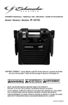
MODEL ACWC-SC
Screw Type
AIR COOLED
PACKAGED CHILLERS
SERVICE MANUAL
I & 0 6500A
INSTALLATION, OPERATION
&
MAINTENANCE INSTRUCTIONS
TABLE OF CONTENTS
DESCRIPTION
PAGE NO.
Inspection & Handling ........................................................................................... 2
Location & Mounting . ....... ... ...... ............................................... ................... . ..... .... 2
Wiring .............................................................................................................. 2
Chiller Piping ..................................................................................................... 2
Start-Up ........................................................................................................ 2 & 3
Maintenance .... . .... . ....... ..... ........... . ........ . ............. ... .... .... ........ .. ......................... 3
Slide Valve Unloading System .................................................................................. 4
Low Ambient Operation ......................................................................................... 5
Control Settings .................................................................................................. 5
Unit Operating Limitations ...................................................................................... 5
Sequence of Operation ...................................................................................... 6 & 7
Models ACWC-160SC Thru 200SC
Sequence of Operation ...................................................................................... 8 & 9
Model ACWC-215SC
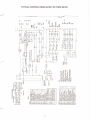
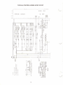
Control Wiring Diagram .................................................................................. 10 & 11
Models ACWC-160SC Thru 200SC
Control Wiring Diagram .................................................................................... 12-15
Model ACWC-215SC
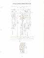
Power Wiring Diagram ............. .... . . .. ... . . ... .... .. ..... . ... .. .... .. ....... ...................... . ........ 16
Across-The-Line Start
Power Wiring Diagram .......................................................................................... 17
Star-Delta
Electrical Data ................................................................................................... 18
Cooler Pressure Drops .......................................................................................... 18
Unit Loading/Suspension Points .............................................................................. 18
Troubleshooting Guide .... .. ........... .... ........... ... .......... . ........... ..... ..... .. .... ... ............ . 19
Causes & Prevention of Freeze-Up ............................................................................ 19
Start-Up Check List ..................................... . ..... .. .. ... . .......................................... 20
Operating Data ... ..... ........... .... . ... .... ..... .. ................ . ...... ........................... ... ...... .. 20
BOHN HEAT TRANSFER
A Gulf+Western Company
Danville, Illinois 61832•{217)446-371 0
.!
I
INSPECTION & HANDLING
CHILLER PIPING
When unit is received, it should be checked for visible or concealed
damage . If damage has occurred it should be reported to the carrier
The chiller inlet (return) water pipe should be connected to the water
connection closest to the control panel end of the unit and the outlet
imm e diately .o.nd clo.im filed .
(:.upply) vvdte• 1-'ifJt:: <..v""""'t"'u tv u,., wat.,r <,;urrrr.,<,;llun on the
Models ACWC 160SC thru 215SC are factory mounted on two (2)
permanent angle beam, carbon steel skids. Eight (8) 2W' lifting eyes
are provided in the skids to allow rigging. Spreader bars must be
used between rigging lines to prevent damage to the unit. Rollers
may be used under the skids to facilitate moving the unit a short
distance. Physical damage to the unit, after acceptance, Is not the
responsibility of the factory.
opposite end of the cooler(s) .
A flow switch must be installed in a straight horizontal section of the
chilled water piping .
Gauges should be installed in the piping to and from the chiller to
measure the pressure drop and to insure the proper (GPM) flow rate
in accordance with submittal data . A strainer should be installed in
the piping on the inlet side of the chiller and vibration eliminators
should be employed on both the inlet and outlet pipes . Air vents
should be located at all high points in the piping system . Vents
should be located to be accessible to servicing . Drain connections
should be provided at all low points to permit complete drainage of
chiller and piping system .
LOCATION & MOUNTING
Model ACWC Air Cooled Packaged Water Chillers are designed for
outdoor application and may be mounted on roof or at ground level.
Air flow through the condenser is vertical and the unit may be
located adjacent to outside of building or on roof without regard for
prevailing wind direction.
The chilled water piping should be insulated to reduce heat pickup
and to prevent condensation . If the system is for year-round
operation or if it will not be drained in the winter, the chilled water
piping should be protected against freezing by electric heating cable
or other suitable means.
Since these units are air cooled, the flow of air to and from the
condenser coil must not be impeded. There must be no obstruction
above the unit that would tend to deflect discharge air downward
where it could be recirculated back to the inlet of the unit. The
required overhead air space should be a minimum of eight (8) feet.
Ductwork must not be applied to the fan outlets.
Upon completion of chiller piping, start the system water pump and
purge air from the system . Air purging should be done from the high
points in the water circuit. Purging of the chiller barrel may be
accomplished through the vent pipe located on the top of the chiller
compartment. Failure to purge air from the water circuit will result in
inadequate waterflow and may cause the unit to cutout on low water
flow freeze protection.
The unit must be installed with sufficient clearance for air entrance
to the condenser coil and for servicing access . The unit should be
located no closer than four (4) feet from any wall or other obstruction .
Clearance must be provided at either end of the unit to permit
removal of tubes from the chiller.
Unit must be set on a solid and level foundation .
..
On roof installations the unit should be mounted on support beams
which span load-bearing walls to prevent excessive vibration .
START-UP
On ground level installations, the unit should be mounted on a
substantial base that will not settle . A one-piece concrete slab with
footings extended below the frost line is recommended. A space
should be left between the slab and the building to prevent the
transmission of sound and vibration .
Refer to start, test, and check list included with this manual.
~·
Check all electrical and mechanical connections for shipping
looseness and tighten all screws on electrical terminals.
Vibration mounts may be used for roof mounted units or other
locations where noise might be objectionable.
Activate the 115 volt chiller and crankcase heater circuit 24 hours
prior to unit start-up .
Rotate each fan prior to start-up. Fans should turn freely. Check belt
tension and pulley alignment. After two (2) weeks of operation,
readjust belt tension to accommodate for belt stretching.
WIRING
A unit wiring diagram showing the required power supply characteristics and all factory supplied wiring details is provided with unit.
Separate, field supplied, disconnects must be installed in the power
supply and should be within the sight of the unit.
Check all control settings as specified in Table 1.
Check the compressor oil level through the crankcase sight glass.
The oil level should be to the top of the glass. If the level is low, add
oil in accordance with the directions in the maintenance instruction
(page 3) .
Separate 115 volt power source must be field supplied to provide
power for control and heater circuits.
.--..,_
2
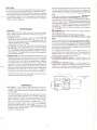
. CAUTION:
Locate the discharge pressure port adjacent to solenoid valve
UL-3 (see drawing below) ; remove the cap and release the
residual pressure by pushing in on the pressure port fitting itself.
Pump oil into this flU' t u11til
uil level Is to the tOP Of the sight
glass .
The discharge line valve must be open before starting the compressor. Liquid line valves must also be open for sustained operation .
All compressors are soli a mountea on 1sopads, therefore, compressor
hold-down bolts must not be loosened . Loosening these bolts will
cause excessive vibration of the compressor and may result in
refrigerant line breakage. Prior to start-up check all compressor
hold-down bolts for tightness .
u,.,
Replace the discharge port cap. Re-open the discharge line valve.
Do not allow compressor to run with discharge valve closed.
Place the system "ON-OFF" switch in the " ON " position . Using a
jumper wire, make a "short" for five (5) seconds between terminal
#4 on terminal block TER5 and the switched terminal of a solenoid
valve feeding the circuit you have just "blown " (e .g . terminal #121
on TER4 to energize SOL 1). Reset return water thermostat (~1) to
the operational temperature setting and allow unit to return to
normal operation .
MAINTENANCE
CONDENSER
Units equipped with belt drive fans have inherently protected
motors. Fan belts , fan bearings and motor bearings require periodic
maintenance as follows:
2. RECOMMENDED OIL- The unit is factory-charged with BOHN
SR-30 refrigeration oil.
Do not add any other type of oil to this factory charge.
Do not operate compressor If oil level is below one-half ('h) sight
glass.
If the oil level is below the minimum specified above, and BOHN
SR-30 is not on hand , you may drain the entire factory oil charge,
then refill with SUN ISO 4GS refrigeration oil. The factory (BOHN)
oil is of the synthetic type and will not mix with SUN ISO 4GS. Do
not attempt to operate the screw compressor with any oil other
than these two specified above .
1. Fan Belts -After two (2) weeks operation , the belts w ill have
nearly reached their permanent stretch , therefore, each belt
should be checked again and proper adjustments made. To
maintain good fan and motor operation , the belt tension should be
checked at three (3) month intervals.
2. Fan Bearings- Each fan shaft is provided with ball bearings of
the relubricatable type. Each bearing is provided with grease
fittings, accessible through the individual motor access panels . It
is recommended the bearings be greased by adding 4 to 5 shots
with a hand gun . The suggested greasing interval is indicated on a
sticker attached to the unit.
It is suggested that a gallon or more of BOHN SR-30 oil be
obtained and kept on hand at the job site. The substitution of
SUNISO 4GS oil, as outlined above, will result in a 2% to 4%
capacity loss, and no reduction in input K.W.
3. Motor Bearings- Each motor is equipped with ball bearings. Ball
bearings consume a very small amount of lubricant, but enough
must be present at all time to prevent motor injury. The length of
time a bearing can run without having grease added or replaced
will depend upon the operating conditions . Under normal
operating conditions, the motor bearings should be lubricated at
2000 hour operating intervals . The lubricant should be from a
clean closed container and should be an anti-friction type bearing
grease-free from solid fillers or other harmful ingredients .
Lubricant should have a safe operating temperature of 2000° F.
3. COMPRESSOR REPAIRS (Internal) - Contact factory or an
authorized BOHN Service Agency if a compressor malfunction is
suspected .
4. COMPRESSOR REPAIRS (External) - Proper operation of
unloaded start , loading , and unloading is controlled by solenoid
valves UL-1 , UL-2 and UL-3. Any of these three (3) solenoid valves
may be repaired or replaced in the field , as required .
The air inlet of the condenser coil should be kept clean through a
regular preventative maintenance program .
HIGH PRESSURE
PORT
COMPRESSOR
1. OIL LEVEL - The oil level in the compressor(s) should be
checked periodically, with the compressor either running or
stopped . If the oil level is below one-half ( '12 ) the sight glass , oil
must be added .
Oil should be added only with the compressor shut off. To do so,
turn the return water thermostat (T1) to a higher temperature
setting , and wait for the unit to pumpdown and shutoff. Place the
system " ON-OFF" switch in the " OFF" position . Close the line
valve in the discharge line between compressor and condenser.
Refrigerant pressure inside of the compressor will now be
approximately 80 to 90 PSI G. The low pressure cut-out setting is
35 PSIG , but the residual discharge pressure (upstream of the
discharge check valve) will equalize back into the suction side
after the compressor stops.
3
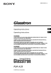
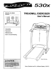
SLIDE VALVE
UNLOADING SYSTEM
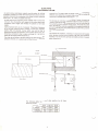
1 ne tlonn screw compressor capacity control system for infinite
modulation consists of a slide valve and hydraulic piston/ cylinder
operator internal to the compressor; plus three hydraulic solenoid
valves (UL-1, UL-2 & UL-3) piped externally.
pressure) line. The slide valve will move to the right (unloading)
whenever UL-2 opens the oil supply (high pressure) line, since the
force of the oil exceeds that of the discharge gas.
The slide valve forms a portion of the chamber wall in which the
rotors turn; thus, its position with respect to the rotors determines
the effective rotor length and thereby the percent of full load
capacity.
The temperature controller sends a series of power (energizing)
" pulses " to the appropriate solenoid to adjust to load conditions.
The further the supply water temperature is from the controller set
point, the longer is the duration of the pulses. The series of pulses
will continue until the controller is satisfied. As the water temperature
approaches the set point, the pulses become quite brief to prevent
overshooting the set point.
Upon compressor start-up, UL-3 is opened. This allows oil pressure
to act upon the hydraulic piston, holding it in the fully unloaded
position . After 30 seconds, during which time full oil flow is
established to all bearings surfaces, UL-3 is closed . At this point, the
temperature controller is free to open and close UL-1 or UL-2 in
response to the supply water temperature.
This method of compressor unloading in conjunction with supply
water sensing minimizes action / reaction lag time and overshoot
resulting in an exceptionally precise and stable control of supply
water temperature.
The slide valve will move to the left (loading) by force of discharge
pressure, whenever UL-1 opens to permit flow to the oil return (low
r
Hydraulic Piston
Load
Unload
c::>
¢::J
Oil Pressure
Vent to
Suction
Slide Valve
~
Oil Pressure Lines
Screw Rotor
UL-1
Oil
Return
Oil
Supply
The following table lists solenoid valve position for all three
operating modes.
Starting
Loading
Unloading
UL-1
Close
Open
Close
UL-2
Close
Close
Open
UL-3
Open
Close
Close
'-...../'
4
LOW AMBIENT OPERATION
Due to the wide range of applications, it is sometimes necessary to
operate the Air Cooled Packaged Water Chillers at ambients below
summer conditions. Without proper control, when ambients drop
below 60° F. the pressure differential between the condenser and
the evaporator is below the level to insure proper thermal expansion
valve operation . As a result, the unit may cycle on low pressure
control with the possibility of evaporator freezing. Three types of
system control are available allowing the units to operate at the
ambients indicated:
This arrangement provides positive start-up control down to +30° F.
by delaying the condenser fan operation until a predetermined head
pressure is obtained.
GRAVITY (Discharge) DAMPERS
LOW AMBIENT CONTROL TO oo F.
(OPTIONAL EQUIPMENT- FACTORY INSTALLED)
All condenser fans are equipped with gravity dampers mounted on
the fan discharge to minimize the effect of prevailing winds; and to
prevent convection drafts up through the condenser coil in still air.
FAN CYCLING
MEDIUM AMBIENT CONTROL TO 30° F.
(STANDARD EQUIPMENT -FACTORY INSTALLED)
All compressors are enclosed in individual insulated housings. An
auxiliary heater is included to supplement the standard crankcase
heater; the temperature within the compressor compartment is
thermostatically controlled .
A fan cycling control is standard on all Air Cooled Packaged Water
Chillers to prov1de prop er operating head pressures, in ambient
conditions to 30° F.
This is an automatic operation in which the condenser fans are
cycled on and off, as required, in response to head pressure. With
two compressors running , three fans are cycled (in sequence) on
five-fan units; four fans on six-fan units; and five fans on seven-fan
units. With one compressor running, all but the lead fan are cycled in
sequence, in response to head pressure.
The standard condenser fan cycling package, operating in conjunction with the discharge dampers , will maintain suitable head
pressure down to oo F. ambient. A 90-second time delay relay
provides an electrical by pass around the low pressure freezestat to
prevent nuisance tnp-out during cold start-up.
ACWC-SC
CONTROL SETTINGS
PRESSURE ACTUATED
High Pressure Control
(Manual Reset)
Pumpdown Control
(Auto Reset)
Fan Cycling Pressure Control
(Adjustable)
Low Pressure Freeze Control
(Manual Reset)
--
TEMPERATURE ACTUATED
Chiller Low Water Temperature Thermostat
Chiller Water Cycling Thermostat (Adjustable)
Chiller Heater Thermostat
(Non-Adjustable
Oil Temperature Safety Control
(Adjustable)
Manual Reset
Capacity Control Thermostat (Adj.) Mode Control Position
-
(."'-._./
1.
2.
3.
4.
5.
LEGEND
HP-1
HP2 & HP3
PD1
PD2 & PD3
2 Fan Cell
FCP 1
FCP 2
3 Fan Cell
FCP 1
FCP 2
FCP 3
4 Fan Cell
FCP 1
FCP 2
FCP3
FCP4
LPF 1
LPF 2 & LPF-3
FACTORY SETTING
Cut-In
300 PISG
Cut-Out
365 PSIG
Cut-In
55 PSIG
Cut-Out
35 PSIG
Cut-In (PSIG)
Cut-Out
280
170
295
180
LEGEND
T2
T1
Included With
CBH1 Heater
FACTORY SETTING
Cut-Out
37° F.
Dial Set At
55° F.
Cut- In
40° F.
Cut-Out
45° F.
OTS 1
OTS 2
OTS3
T3
260
275
290
160
175
215
260
275
285
295
Cut-Out
160
175
210
235
54 PSIG
Cut-Out
240° F.
Dial Set At
44° F.
UNIT OPERATING LIMITATIONS
Maximum ambient air to condenser is 115° F. (60 Hertz operation).
Maximum allowable cooler water pressure is 150 PSI G.
Maximum allowable water temperature to cooler is 75° F.
Units must not have leaving water temperatures of 42° F. or lower unless used with a glycol solution.
Unit must be allowed to pumpdown at the end of each operating cycle (except on safety control shutdown).
5
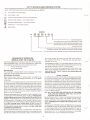
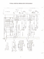
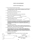
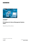
KEY TO WIRING DIAGRAM INDEXING SYSTEM
The wiring diagrams and sequence instructions on the following pages have been devised to simplify the understanding and tracing of circuit
theory. The following key shows how the indexing system can be used.
12
Line number on wiring diagram
[12]
Line number in text
(RS)
Component identification symbol in text (Relay #5)
~
Normally open contact- line number location
~
Normally closed contact- line number location
@
Holding coil -
&
Note number
line number location
EXAMPLE
30
~ §] §]
@@&
~
See Note Number 3
The holding coil for the first contact shown on this
line (reading from left to right) can be found on line
#44; the holding coil for the second contact can be
found on line #74.
The contacts for the holding coil shown on this line can be found on
lines 66, 23, and 54. The contact on line 23 is normally closed .
This is the number which identifies the line of wiring shown at the left.
SEQUENCE OF OPERATION
MODELS ACWC 160 To 200 SC
and #15 [63] provide an interlock for the water pump starter(s);
either contact (R14). (R16), or (R18) [62] will close any time a
compressor is running.
The following sequence of operation is typical for the ACWC 160 to
200 SC (see Pages 10 and 11 for typical wiring diagram). Refer to the
wiring diagram furnished with unit for specific information.
Set the staging thermostat (T1) to the design range of operation (e.g .
54° F. return water) . Set the capacity control thermostat (T3) to the
design range of operation (e.g. 44° F. supply water) .
Control Identification Symbol
Place the four (4) control circuit switches (SW1-SW4) in the "ON"
position , thus energizing the balance of the control circuit. The
system will be In the "Time-In" mode for five minutes before any
compressor will start.
Circuit Line Number
Important Notel
The compressor crankcase heater must be energized and remain
active for a minimum fa 24 hours prior to unit start-up.
PRELIMINARY SEQUENCE
STAGE 1 LOADING
Upon demand for cooling, the first step of the staging thermostat
(T1) will close, energizing relay (TD10) (63] and staging relay (R1)
[62]. closing (R1) contacts 7-4 [22]. 8-5 [25]. and 9-6 (16] . If the
safety controls and switches are closed, the control circuit [16] for
compressor No.1 and liquid line solenoid (SOL 1) (25] will energize,
allowing the compressor to start. Fan contactor (C13) (21] will also
close, bringing power to the line side of fan cycling pressure
controls (FCP1) and (FCP2) (see Power Wiring Diagram- Pages 16
and 17). Fan motor #1 will start as soon as the head pressure reaches
the "cut-in" setting of (FCP1 ).
Place control circuit "ON-OFF" switches (SW1 thru SW4) in the
"OFF" position, and set the staging thermostat (T1) to its highest
temperature.
Activate the 115 volt electrical service to terminals #2 and #4 [1 and
3] on terminal board (TEAS) to distribute power to the control circuit
up to the control circuit switches. Crankcase heater relay contacts
(R19) (3]. (R20) [5]. and (R21) [7] are closed and are supplying
power to the compressor crankcase heaters. Power is also supplied
to the chiller barrel heater (CBH1) (11]. the receiver heaters (RH1, 2,
3) (8, 9, 10] (optional), and the low ambient crankcase heaters
(SCH1, 2, 3) [3, 5, 7] (optional).
, -~
NOTE: ALL FAN MOTORS ARE CONTROLELD BY THEIR OWN
FAN CYCLING CONTROL AND WILL CUT IN AT
DIFFERENT HEAD PRESSURES.
Close the main power disconnect switch. Check to see that the red
indicating light on the phase loss monitor (PLM1) is lit (NOTE: There
will be two phase loss monitors, (PLM1) and (PLM2), on 208-230 volt
models). This light must be on to indicate proper phase rotation for
the compressor(s) . If the light is not on, the main control circuit to
the compressors will not be energized. Reverse any two phase legs
at the Main Incoming Power Terminal Block. DO NOT reverse the
leads on the phase loss monitor, for this will allow the compressor to
run backwards, causing severe damage, and WILL VOID THE
COMPRESSOR WARRANTEE!
Relay (R19) [20] contact 7-1 [3] opens, de-energizing compressor#1
crankcase heater(s). Relay (R14) (19] contact 8-5 (24] closes,
energizing (TD7) [23]. This will force compressor #1 to run for five
minutes. COMPRESSOR #2 CANNOT BE STARTED UNTIL (TD7)
TIMES OUT.
Time delay relay (TD1 0) [63] contact C-NC (26] holds the compressor
in an unloaded condition for 30 seconds. When relay (TD10) times
out, it will energize relay (R4) [27]. closing contacts 9-6 [71] and 7-4
[74] . This allows the capacity control thermostat (T3) to energize
solenoid valve (UL 1-1) [71]. loading the compressor; or to energize
solenoid valve (UL2-1) [74]. unloading the compressor.
Start-up the chilled water pump. The water flow is confirmed when
the water flow switch completes an electrical circuit across terminals
#12 (58] and #13 [60] of terminal board (TEAS). Terminals #14 [61]
6
\....__./
Relay (R14) (19] contact 7-4 [62] closes, which completes the
interlock circuit for the water circulating pump.
~TAGE!
PUMPDOWN SEQUENCE
STAGE 3 PUMPDOWN
A dccrca:>e in return water temperature will t;iiU>Se the third step or
the staging thermostat (T1) to open, thereby de-energizing staging
relay (R3) , opening contacts 8-5, 9-6, and 7-4. Liquid line solenoid
(SOL3) will de-energize, stopping the flow of refrigerant to chiller
circuit #3. The compressor will continue to run until the chiller
circuit has been cleared of refrigerant and the suction pressure is
approximately 35 PSIG . Low pressure control (LP3) contact will
then open, de-energizing compressor contactors (C5) (49] and (C6)
[50]. stopping compressor #3; and de-energizing relays (R18) and
(R21 ). Relay (R18) N.C. (normally closed) contact 2-8 (54] energizes
lock-out timer (TD6). preventing compressor #3 re-start for . five
minutes. Relay (R21) energizes the compressor crankcase heater(s).
Z LOADINu
Upon a further increase in return water temperature, the second step
of the staging thermostat (T1) will close. If the lock-out timer (TD5)
and the lock-in timer (TD7) [64] have timed out, relays (R2) [64] and
(TD11) [65] will be energized, closing (R2) contacts 9-6 [32]. 8-5
[40]. and 7-4 [37]. If the safety controls and switches are closed, the
control circuit [32] for compressor #2 and liquid line solenoid
(SOL2) [ 40] will energize, allowing the compressor to start.
Relay (R20) [36] contact 7-1 [5] opens, de-energizing crankcase
heater(s). Contact 9-6 [44] closes, energizing fan contactor (C14)
(44]. bringing power to the line side of the balance of the fan cycling
pressure controls (see power wiring diagrams) . Fan motor #3 will
start as soon as the head pressure reaches the "cut-in" setting of
(FCP3) .
Staging thermostat (T1) also de-energizes relay (R7). opening
contact 9-6, releasing compressor #1 from continuous full-load
operation. Relay (R7) contacts 8-2 and 7-1 close, allowing the
capacity control thermostat (T3) to operate capacity control solenoid
valves (UL1-1) and (UL2-1) as required .
Relay (R16) [35] contact 8-5 [39] closes , energizing (TD8) (38]. This
will force compressor #2 to run for five minutes. Compressor #3
cannot be started until (TDS) times out.
STAGE 2 PUMPDOWN
A further decrease in return water temperature will de-energize
staging relay (R2), closing liquid line solenoid (SOL2) . When chiller
circuit #2 has pumped out, low pressure control (LP2) opens,
stopping compressor #2; and de-energizing relays (R16) and (R20) .
Relay (R16) N.C. contact (8-2) [38] energizes lock-out timer (TD5),
preventing compressor #2 re-start for five minutes. Relay (R20) (36]
energizes compressor#2 crankcase heater(s); and also de-energizes
fan contactor (C14) (44]. stopping the fan motor(s) servicing the
two-circuit condenser slab.
Time delay relay (TD11) [65] contact C-NC (41] holds compressor#2
in an unloaded condition for 30 seconds. When (TD11) times out, it
will energize (R5) (42]. closing contacts 9-6 (72] and 7-4 (75] . This
allows the capacity control thermostat (T3) to energize solenoid
valve (UL 1-2) [72]. loading the compressor; or to energize solenoid
valve (UL2-2) [75]. unloading the compressor.
STAGE 1 PUMPDOWN
Step 1 of the staging thermostat (T1) will open when the return water
temperature is reduced to the set point . This de-energizes staging
relay (R1 ), closing liquid line solenoid (SOL 1), stopping refrigerant
flow to chiller circuit #1. Compressor#1 continues to run until chiller
circuit #1 pressure is down to the low pressure control (LP1) set
point. The (LP1) contact opens, de-energizing compressor contactors (C1) (17]. (C2) (18], and fan contactor (C13) [21]. stopping
compressor #1 and the remaining fan motor(s).
STAGE 3 LOADING
Upon a further increase in return water temperature, the third step of
the staging thermostat (T1) will close. If the lock-out timer (TD6) and
the lock-in timer (TD8) (66] have timed out , relays (R3) (66]. (R7)
(68]. and (TD12) [67] will be energized . Relay (R3) contacts 9-6 [48].
7-4 [53]. and 8-5 [56] close. If the safety controls and switches are
closed, the control circuit [ 48] for compressor #3 and liquid line
solenoid (SOL3) [56] will energize, allowing the compressor to start.
Relay (R14) N.C. contact 8-2 (23] energizes lock-out timer (TD4),
preventing compressor #1 re-start for five minutes ; relay (R14)
contact 7-4 (62] opens, removing the circulating pump starter
interlock . Relay (R19) de-energizes, closing contacts 7-1 [3].
energizing compressor #1 crankcase heater(s) .
Relay (R21) [52] energizes , opening contact 7-1 [7], de-energizing
compressor #3 crankcase heater(s). Relay (R18) (51] contact 8-5
[55] closes, energizing (TD9) [54] . This will force compressor #3 to
run for five minutes.
SAFETY CONTROLS
Each refrigerant circuit is protected by seven standard safety
controls, and one optional safety control.
1.
2.
3.
4.
5.
6.
7.
8.
Relay (R7) contact 9-6 [70] closes, energizing solenoid valve (UL 11). thus locking compressor #1 in the fully loaded position. Relay
(R7) contacts 8-2 [71] and 7- 1 [74] open to disconnect the capacity
control thermostat (T3) from compressor #1 capacity control
solenoid valves.
Time delay relay (TD12) [67] contact C-NC [57] holds compressor
#3 in an unloaded condition for 30 seconds. When (TD12) times out,
it will energize relay (R6) [58]. closing contacts 9-6 [73] and 7-4 [76].
This allows the capacity control thermostat (T3) to energize solenoid
valve (UL 1-3) [73]. loading the compressor; or to energize solenoid
valve (UL2-3) [76]. unloading the compressor.
High Pressure (HP)
Low Pressure Freeze (LPF)
High Discharge Temperature (OTS)
Low Oil Temperature (LOT)
Compressor Solid State Module (CSTM)
Low Water Temperature (T2)
Low Pressure (LP)
Compressor Starter Overloads (OLH) (Optional)
If any of these devices should open due to abnormal conditions, the
compressor will automatically stop. All controls must be manually
reset , except Low Oil Temperature (LOT), Low Pressure (LP) and
Compressor Solid State Module (CSTM), which resets itself after a
two minute bleed-down period. The compressor motor windings are
also equipped with a thermal protector, automatic reset , which is not
shown on the wiring diagram .
Compressor #1 is fully loaded.
Compressors #2 and #3 are being capacity-modulated.
,.-......__/
7
SEQUENCE OF OPERATION
MODEL ACWC 215 SC
solenoid valve (UL2-1) [1 12], unloading the compressor.
Relay (R11 ) [29] contact 7-4 [95] closes , wh ich completes the
interlock circuit for the water c irculating pump.
STAGING 2 LOADING
Upon a further increase in return water temperature, the second step
of the staging thermostat (T1) will close. If the lock-in timer (TD9)
[95] and lock- out timer (TD7) [95] have timed out , relays (R2) [95]
and (TD16) [96] will be energized , closing (R2) contacts 9-6 [62], 7-4
(67], and 8-5 [70] . If the safety controls and switches are closed , the
control circuit [ 62] for compressor #3 and liquid line solenoid
(SOL3) [70] will energize, allowing the compressorto start.
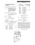
The following sequence of operation is typica l for the ACWC 215 SC
(see pages 12 to 15 for typical w iring diagram ). Refer to the wiring
diagram furnished with un it for specific information.
(
)
Control Identification Symbol
[
]
Circuit Line Number
Important Notel
The compressor crankcase heate r must be energized and remain
active a minimum of 24 hours prior to unit start.
PRELIMINARY SEQUENCE
Place control circuit " ON-OFF" switches (SW1 thru SW5) in the
" OFF" position , and set the staging thermostat (T1 ) to its highest
temperature.
~
\
Relay (R22) [66] contact 7-1 [8] opens, de-energizing crankcase
heater(s). Contact 9-6 [74] closes , energizing fan contactor (C14)
[74], bringing power to the line side of fan cycling pressure controls
(FCP7) thru (FCP12) (see power w iring diagrams) . Fan motor#4 will
start as soon as the head pressure reaches the " cut-in " setting of
(FCP7) .
Activate the 115 volt electrical service to terminals #2 and #4 [ 1 and
3] on terminal board (TER5) to distribute power to the control circu it
up to the control c ircuit switches. Crankcase heater relays (R20) [3],
(R21) (5], (R22) [8], and (R23) (10] are closed and are supp ly ing
power to the compressor crankcase heaters . Power is also supplied
to the chiller barrel heaters (CBH1) [17] and (CBH2) [20], the
receiver heaters (RH1 , 2, 3, 4) (12, 13, 15, 16] (optional) , and the low
ambient crankcase heaters (SCH1 , 2, 3, 4) [3, 5, 8, 10] (optional) .
Relay (R13) [65] contact 8-5 [69] closes, energizing (TD11) [68] .
This will fo rce compressor #3 to run fo r five minutes . Compressor#2
cannot be started until TD11) times out.
Time delay relay (TD16) [96] contact C-NC [71] holds compressor
#3 in an unloaded condition for 30 seconds . When (TD16) times out,
it will energize (R7) [72], closing contacts 9-6 [1 08] and 7-4 [113] .
This allows the capacity control thermostat (T3) to energize solenoid
valve (UL 1-3) [108], loading the compressor; or to energize solenoid
valve (UL2-3) [113], unload ing the compressor.
Close the main power disconnect switch. Check to see that the red
indicating lights on the phase loss monitors (PLM1 ) and (PLM2) are
lit. These lights must be on to indicate proper phase rotation for the
compressor(s). If the lights are not on , the main control circuit to the
compressors will not be energized . Reverse any two phase legs at
the main Incoming power terminal block. DO NOT reverse the leads
of the phase loss monitor, fo r this w ill allow the compressor to run
backwards, causing seve re damage , and WILL VOID THE
COMPRESSOR WARRANTEE!
STAGE 3 LOADING
Upon a further inc rease in return water temperature, the th ird step of
the staging thermostat (T1) will close. If lock-in timer (TD11) and
lock-out timer (TD6) [66] have timed out, relays (R3) [97], (R9) [99],
and (TD17) (98] wil l be energized . Relay (R3) contacts 9-6 [45], 8-5
and 7-4 [50] close . If the safety controls and switches are closed , the
control circuit [45] for compressor #2 and liquid line solenoid
(SOL2) [53] will energize, allowing the compressor to start.
Start-up the chilled water pump. The water flow is confirmed when
the waterflow switch completes an electrical circuit across terminals
#12 [89] and #13 [91] of terminal board (TER5) . Terminals #14 [92]
and #15 (94] provide an interlock for the water pump starter(s) ;
either contact (R11 ), (R12) , (R13) , or (R14) [95] will close any time a
compressor is running .
Relay (R21) [49] energizes , opening contact 7-1 [5], de-energizing
compressor #2 crankcase heater(s) . Relay (R12) [48] contact 8-5
[52] closes , energizing (TD1 0) [51] . This will force compressor#2 to
run for f ive minutes. Compressor #4 cannot be started until (TD10)
times out.
Set the staging thermostat (T1) to the design range of operation (e.g.
54° F. return water). Set the capacity contro l thermostat (T3) to the
design range of operation (e.g . 44° F. supply water) .
\....__/
Relay (R9) contact 9-6 [1 05] closes, energizing solenoid valve (UL 11), thus locking compressor #1 in the fully loaded position . Relay
(R9) contacts 8-2 [106] and 7-1 [112] open to disconnect the
capacity control thermostat (T3) from compressor #1 capacity
control solenoid valves.
Place the five control circuit switches (SW1 thru SW5) in the " ON "
position , thus energizing the balance of the control circuit. The
system will be in the "time-In" mode for five minutes before any
compressor will start.
Time delay relay (TD17) [98] contact [54] holds compressor#2 in an
unloaded condition for 30 seconds. When (TD17) times out, it will
energize relay (R6) [55], closing contacts 9-6 [109] and 7-4 [114] .
This allows the capacity control thermostat (T3) to energize solenoid
valve (UL 1·2) (1 09], load ing the compressor; or to energize solenoid
valve (UL2-2) (114], unloading the compressor.
STAGE 1 LOADING
Upon demand for cooling , the first step of the staging thermostat
(T1) will close, energizing relay (TD15) [94] and staging relay (R1)
(93], closing (R1) contacts 7-4 [32], 8-5 [35], and 9-6 [26] . If the
safety controls and switches are closed , the control circuit [26] for
compressor #1 and liquid line solenoid (SOL 1) (35] will energize,
allowing the compressor to start.
Compressor #1 is full loaded .
Compressors #2 and #3 are being capacity-modulated .
Relay (R20) (30] contact 9-6 (39] closes, energizing fan contactor
(C13) (39], bringing power to the line side of fan cycling pressure
controls (FCP1) thru (FCP6) (see Power Wiring Wiring Diagram on
Pages 16 and 17) . Fan motor #1 will start as soon as the head
pressure reaches the " cut-in " setting of (FCP1 ).
STAGE 4 LOADING
Upon a further increase in return water temperature, the fourth step
of the staging thermostat (T1) will close. If the lock-in timer (TD1 0)
and the lock-out timer (TD8) [1 00] have timed out, relays (R4) [1 00],
(R1 0) (1 02], and (TD18) [1 01] will be energized . Relay (R4) contacts
9-6 [79], 7-4 (84], and 8-5 [87] close. If the safety controls and
switches are closed , the control circuit [79] for compressor #4 and
liquid line solenoid (SOL4) [87] will energize , allowing the com presso r to start.
NOTE: ALL FAN MOTORS ARE CONTROLLED BY THEIR OWN
FAN CYCLING CONTROL AND WILL CUT IN AT
DIFFERENT HEAD PRESSURES.
Relay (R20) contact 7-1 (3] opens, de-energizing compressor #1
crankcase heater(s) . Relay (R11) [29] contact 8-5 [34] closes ,
energizing (TD9) [33]. This will force compressor #1 to run for five
minutes. COMPRESSOR #3 (Stage 2) CANNOT BE STARTED
UNTIL (TD9) TIMES OUT.
Relay (R23) [83] energizes, opening contact 7-1 (7], de-energizing
compressor #4 crankcase heater(s). Relay (R14) [82] contact 8-5
(86] closes, energizing (TD12). This will force compressor #4 to run
for five minutes.
Time delay relay (TD15) ]94] contact C-NC [36] holds the compressor
in an unloaded condition for 30 seconds . When relay (TD15) times
out, it will energize relay (R5) (37], closing contacts 9-6 [1 06] and 7-4
(112]. This allows the capacity control thermostat (T3) to energize
solenoid valve (UL 1-1) [1 06], loading the compressor; or to energize
8
Relay (R1 0) contact 9-6 [1 07] closes, energizing solenoid valve
(UL1-3 , thus locking compressor #3 in the fully loaded position .
Relay (R1 0) contacts 8-2 (1 08] and 7-1 [113] open to disconnect the
capacity control thermostat (T3) from compressor #3 capacity
control solenoid valves.
~~
'-.._/
Time delay relay (TD18) (101] contact C-NC (88] holds compressor
#4 in an unloaded condition for30 seconds. When (TD18) times out,
it will energize relay (R8) [89]. closing contacts 9-6 [11 0) and 7: 4
preventing compressor #3 re-start for five minutes. Relay (R22)
energizes compressor #3 crankcase heater(s); and also de-energizes
fan contactor (C14) [74). stopping the fan motor(s) on the "lag" half
(116]. Thio o.llowo tho capacity control thormootat (T'l) to .. norgi:zo
nf thA condAn!':Ar !':lab.
solenoid valve (UL 1-4) [11 OJ, loading the compressor; or to energize
solenoid (UL2-4) [115) , unloading the compressor.
STAGE 1 PUMPDOWN
Step 1 of the staging thermostat (T1) will open when the return water
temperature is reduced to the set point. This de-energizes staging
relay (R1 ), closing liquid line solenoid (SOL 1), stopping refrigerant
flow to chiller circuit #1 . Compressor#1 continues to run until chiller
circuit #1 pressure is down to the low pressure control (LP1) set
point. The (LP1) contact opens, de-energizing compressor contactors (C1) (27) and (C2) [28), and relay (R20), stopping compressor
#1 . Relay (R20) de-energizes fan contactor (C13), stopping the
remaining fan motor(s); and also energizes compressor #1 crankcase
heater(s) . The (LP1) contact also de-energizes relay (R11 ). Relay
(R11) N.C. contact 2-8 [33) energizes lock-out timer (TDS), preventing compressor #1 re-start for five minutes. Relay (R11) contact 7-4
[95) opens, removing the circulating pump starter interlock.
Compressors #1 and #3 are fully loaded .
Compressors #2 and #4 are being capacity-modulated.
PUMPDOWN SEQUENCE
STAGE 4 PUMPDOWN
A decrease in return water temperature will cause the fourth step of
the staging thermostat (T1) to open , thereby de-energzing staging
relay (R4), opening contacts 8-5, 9-6, and 7-4. Liquid line solenoid
(SOL4) will de-energize, stopping the flow of refrigerant to chiller
circuit #4. The compressor will continue to run until the chiller
circuit has been cleared of refrigerant and the suction pressure is
approximately 35 PSIG. Low pressure control (LP4) contact will
then open, de-energizing compressorcontactors (C7) [80) and (C8)
[81), stopping compressor #4; and de-energizing relays (R14) and
(R23) . Relay (R14) N.C. (normally closed) contact 2-8 [85] energizes
lock-out timer (TD8), preventing compressor #4 re-start for five
minutes. Relay (R23) energizes compressor#4 crankcase heater(s) .
Staging thermostat (T1) also de-energizes relay (R10) , opening
contact 9-6, releasing compressor #3 from continuous full-load
operation. Relay (R1 0) contacts 8-2 and 7-1 close, allowing capacity
control thermostat (T3) to operate capacity control solenoid valves
(UL1-3) and (UL2-3) as required.
r
SAFETY CONTROLS
STAGE 3 PUMPDOWN
A further decrease in return water temperature will de-energize
staging relay (R3), closing liquid line solenoid (SOL2) . When chiller
circuit #2 low-side has pumped out, low pressure control (LP2)
opens, stopping compressor #2; and de-energizing relays (R12) and
(R21 ). Relay (R12) N.C. contact 2-9 [51) energizes lock-out timer
(TD6), preventing compressor #2 re-start for five minutes. Relay
(R21) energizes compressor #2 crankcase heater(s) .
Each refrigerant circuit is protected by seven standard safety
controls, and one optional safety control.
1.
2.
3.
4.
5.
6.
7.
8.
Staging thermostat (T1) also de-energizes relay (R9), opening
contact 9-6, releasing compressor #1 from continuous full-load
operation. Relay (R9) contacts 8-2 and 7-1 close, allowing the
capacity control thermostat (T3) to operate capacity control solenoid
valves (UL 1-1) and (UL2-1) as required .
High Pressure (HPO)
Low Pressure Freeze (LPF)
High Discharge Temperature (OTS)
Low Oil Temperature (LOT)
Compressor Solid State Module (CSTM)
Low Water Temperature (T2)
Low Pressure (LP)
Compressor Starter Overloads (OLH) (optional)
If any of these devices should open due to abnormal
conditions, the compressor will automatically stop. All
controls must be manually reset , except Low Oil Temperature (LOT) , Low Pressure (LP) and Compressor Solid
State Module (CSTM), which resets itself after a two
minute bleed-down period . The compressor motor windings are also equipped with a thermal protector, automatic
reset, which is not shown on the wiring diagram .
STAGE 2 PUMPDOWN
A further decrease in return water temperature will de-energize
staging relay (R2), closing liquid line solenoid (SOL3) . When chiller
circuit #3 has pumped out, low pressure control (LP3) opens,
stopping compressor#3; and de-energizing relays (R13) and (R22).
Relay (R13) N.C. contact 2-8 [68) energizes lock-out timer (TD7),
STAR-DELTA STARTING
OPEN TRANSITION
~
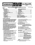
·The following starting sequence applies to the power wiring diagrams
on Page 17 as well as the control wiring on Pages 10 thru 15. Detail
"A" on Page 10 is typical of all screw compressor star-delta start, and
will be used as an example.
Staging relay (R1) contact 9-6 [16) closes, energizing star contactor
(S1) [168) and the 5 second transition timer (TD1) [16A) . The (S1)
power contacts close, tying the center legs of the motor windings
together into the "star" (wye) configuration. The (S1) N.C. (normally
closed) auxiliary contact [18] opens to prevent contactor (C2) from
energizing. The (S1) N.O. (normally open) auxiliary contact [17)
closes, energizing (C1) [17] . The (C1) power contacts close,
applying power to the motor. The (C1) N.O. auxiliary contact closes,
locking (C1) in the energized position .
The compressor operates in the star mode until (TD1) times out (5
seconds) at which time (TD1) contact (168) opens, de-energizing
(S1 ). The (S1) N.C. contact [18) closes, energizing contactor (C2)
[18), closing (C2) power contacts, thereby completing the Delta
wiring configuration. (C2) N.C. auxiliary contact [16A] opens,
preventing (S1) from energizing until the next starting sequence.
There is an instant of time (the "open transition " ) between the
opening of (S1) power contacts and the closing of (C2) power
contacts, in which power across the motor windings is interrupted .
9
0
NOTE
WITH
LINE NO.
LINE NO.
CONTACTS WITH LINE NO.
CONTACTS WITH
CLOSED
NORIIIALL'f Of>EN
NORMALLY
HOLDING COILS WITH LINE NO.
!I SEC
DETAIL "B"
- )
!!iSEC
STAR DELTA STARTING
DETAIL "A"
STAR DELTA STARTING
(NOT SUPPLIED WITH BELL OPTION.)
I
CIRCUIT 2
'
I
I
I
I
I
I
:vuu
OPTIONAL
207
1
1
L-
~
21.3
M
~
GFI
~PfiO"HAL
[
123
L-
c;
N
R
~-
Ml
~~
226
8 Rl9 5
GF 2
SW3
OPTiONAL
'
COMPRESSOR CIRCUIT 2
BLUE
R
~~
~
SJ,._
itt
4
2
5
5
!
TO
-
0LH4
R2
5
6
rlJ"':
8
B
30 SEC
Tl
NO
Ml
tl2
NC 244
N~NT
TDB
229
128
NO
8
5
230
R20
OLH6
~30 SEC
5
7
OLH5
WHEN SUPPLIED
228
zoow
~
!lOW I~
.
I
II
===::::J
IH
WHITE
12GA
~H~:E
I 12 GA
1!31
""~
=
225
9
6
Tl
~
SOLI
A TOT
8
L--e-
UL3-I
~TI-o2
HGS I
r l
C).
~
WHITE
-e-
~-'-----~
OETAIL"AMQ
~
r
S~~;.N
12ovl
LPFI
HTR
~SEE
T2
c;7
~
121
6 120
i·d·
RI4
2 ':L7~
Rl
f~I!Jr
:
I
: -------"l OPTIONAL
or~
LEir "cd
!
I
r--r==e-
CBH I
RH 3
RH2
RH I
~;~~OPT.
~-;--~0~
.-=---~oPT
I~
!lOW I~ .
PCH2
~~
=I
WHITE
142 WHITE
9
245
BLUE
R2
6
r ~~~ r
9~~~6
235
y
:::E
~
R LP2
227
RED
~
Nl "=Z._
S~~.:N
129
SEE
8
UL3-2
w;;:
~
R5J-----..J
SOL 2
A T0
5
Q
~
Co::\'-----~
~
LPF 2
~81:::":\
HTR
DETAIL
Tl
~
[
~
T2
120vl
~OPTIONAL
i9oSEc wmE
~
128
127
-
R4 } - - - - - - '
0
~
-
122
IO>~H$)C'-------------:<!?;-------<>-1...o--1
~
5111~N1
I ~IRED
Y R
8
1/S
v 9
W
-
R LPI
224
7 T07 1
OLH2
..., 211...,212
J
119
RED
8f1
J: -~g-
R- c:!r.- 8
_
~3
M2
WIRED WHEN SUPPLIED
8
~HI
-....,-2 10
C:,
11
,...
_
TH
zoow
..::=--~oPT
PCHI
148
147
146
145
R22\+--------------_.
116
'''
114
113
112
Ill
4
7lJI
216
Tl
CST• .
Co
~--;~
206
20!1
204
61
I
,I
I
r-c=-~_j
~22
OPTIONAL
RHT3
.. ::.
RHTZ
RHTI
I
~222
t
I
I : I cSTw'
-,-,-,.Jy J25-UiT-,-,-,-0-iS~Y~34 11 -:i
LP'Il: 2
:I
OPTIONAL
r:;-
215 ors1
1----Q 117
COMPRESSOR CIRCUIT I
'--,~,~,--+<,_,.,
[
BLUE
R
Lon
r-~sr-
R- .0. 8
118
y --- ---
..__ __.!R~E£_0----<,::SW;:._;,'
273
f"'T.
A-LPFI 2 14 HPI
J
BLACK
110 BlACk
RZO
)
Rl9
R.z2~
OPPrfiOfll
7
7 R21
7
7
J,J! I
203
RHPC
YELLOW.~
201
YEUOW
BLUE
202
~
-,,PC
1...---o~
I:
_R;_I
BLUE
-109 REO
108-
I
o-
RED
C8FI
I
t::tl.)
~-
OPTIONAL
~
L _ y_ ____j
1
OPTIOHAlr----
..--.....
CB2
rT
l
~:·o 1J
Iii..J! i
L
1
':JT
_j=PUoll
8
CBI
4 BLACK
12GA
1----l.-- _~.-
[
I
9
10-
I
I
:
I
l
0-r--
4
2
1~~
I
ALARM CIRCUIIIT
r
•
POWER SUPPLY
115V/60'\,/IIf
TYPICAL. FOR UGHT OPTION ON ALARM CIRCUITS 1,2 8 3.
0
6
0
0
DESIGNATIONS :
..
Rrt-
~
~
~
1!3
~'i!il·~
13*91821
~
ETI!3
~
§]
~
li!m
~
~
@
00
®§
8
@)
l9
®
@).§)
€X§
@)
@
@
@
®
®
®
®
®
@
®
~
8
&
&
&,
&
&
&
&
&6
&
J
I
~
u
"
l
J
~
z
.
"
~
u
-
j
§
u
.~
l
0
C/)
0
0
N
c
~
-1
:I:
0
~
en
~
0
>
0
G)
z
~
0
r
~
~
-4
z
0
0
>
r
0
-4
.,<
CIRCUIT BREAKER- CONTROL CIRCUIT
CIRCUIT BREAKER- HEATERS
CB l, 4
LOW OIL TEMPERATURE
LOW PRESSURE CONTROL
I LOW PRESSURE
I OIL TEMPERATURE SAFETY
I PHASE LOSS MONITOR
!RELAY-STAG ING
RELAY - CAPACITY CONTROL
LOT 1-3
LPI - 3
LPF I · 3
OTS I· 3
PLM 1
Rl -3
SWl - 4
I TINE DELAY- CYCLING
TRANSITION CONTACTOR
TI N E DELAY - TRANSITION CONTACTOR
TC 1-3
TO 1-3
VOLT LOSS MONITOR
STARTER - COMPRESSOR
TO 13 - 15 I TINE DELAY- LOCI<· OUT LPF
SECONDARY CRA NI<CASE HEATER
SCH I· 3
CIRCUIT BREAI<[R- RtC. HEATER
RECEIVER HEAT ER THERMOSTAT
RELAY- SECONDARY HEATERS
PILOT LIGHTS
RECE IVER HEATER
RECEIVER HEATER PRESSURE CONTROL
R 22
RH 1·3
PL I· 9
PR IMARY COMPRESSOR HEATER
THERMOSTAT
OVERLOAD HEATERS - STARTERS
OLH 1-9
LOW AMBIENT
HOT GAS SOLENOID
I GROUND FAULT PROTECTION
AMBIENT HIGH TEMPERATURE THEA"'.
PCH I · 3
GF 1- 3
OPTIONAL
Q
TERMINAL BOARD-FACTORY WIRING
UNLOADERS-SOLENOIO COMPRESSOR
0
TERMINAL BOARD-CUSTOMER WIRING
~~ ;o~~2 ~:=~ ~~~:~ ~ ~A~~~~~~c~~:TROL
TO 4-8
THERMOSTAT- CAPACITY CONTROLLER
] THERMOSTAT- LOW TEMPERATURE
THERMOSTAT - SEQUENCER
I SWITCH- COMPR. CIRCUITS
SOLI · 3
TZ
I RELAY-CRANI<CASE
I SOLENOID-LIQUID LINE
R 19 -21
Rl4, 16, IB I RELAY - TNTEIIILOCK
SWITCH- MASTER
RELAY - LOCK IN
I HIGH PRESSURE CONTROL
HPI -3
FREEZE
! COMPRESSOR SOLID STATE NODULE
CSTMI ·3
CHILLER BARREL HEATER
CONTACTOR - CONDENSER FAN
CBI
"c"
Cl3-14
CONTACTOR - COioiPRESSOR
STA NDARD
LEGEND
DETAIL
SSEC
I
STA R DELTA STARTI NG
QI
I
YELLOW
·
r;==
I T2 AND T3 TEMP. SENSORS LOCATED IN
WATER OUTLET, Tl IN WATER INLET.
2. WHEN TO 13,14 a IS ARE SUPPLIED ,
WIRE S FROM 120,127 a 133 TO T2
BE CO JojE 218, 236 8 255 RESPECTIVELY.
l. WHEN LATI IS NOT SUPPLIED, WIRE 265
BECOMES 13.
4. WHEN GF!,GF2 8 GF3 ARE NOT SUPPLIED,
WIRES 213, 231 8 250 BECOME 117, 124 8
130 RESPECTIVELY.
5 FOR CONTACTOR COILS Cl THRU C6, Cl3 8
C 14, SEE MAIN POWER DIAGRAM FOR
CONTACTS
6. ALARM LIGHT OPTION AND ALARM BELL
OPTION ARE NOT SUPPLIED SIMULTANEOUSLY.
7. WHEN VLN I IS NOT SUPPLIED, WIRE 209
8ECOio4ES 272 .
NOTES
TO PUMP MOTOR
INTERLOCK.
REMOTE SWITCHES!
TO 8£ WIRED IN
SERIES
ALARM CIRcunl
1
CIRCUIT3
'
I
NO
WHITE
,., ..
'"
...
140
UL2-3
UL2 ·2
UL2· 1
ULI -3
UL I-1
.•• 1
WHITE
R6}-----_j
"
77
76
"
H
"
72
70
..
"
60
,.
~
®
00
00
@
®
@
&/!::,.
&
&
&
&.
&
€€.>
1701~1~
~
®
®
@@
®
@
00 &
@
~@§>
@)
\32137149
~
\1s\22\z5l ~
58@
~
~
L:.J..I•~
§ol>ol<•l
~
@
@
@
~
u
"5
~
l
{
0
en
0
0
N
c:
::D
:I:
-t
0
0)
~
:e0
0
z
C)
)>
::D
:e
0
r
::D
-t
z
r
0
0
)>
0
-t
.,<
"'
~
NOTE WITH LtNE NO,
\
'
DETAIL "A "
STAR DELTA STARTIN G
(NOT SUPPLIED WITH BELL OPTIOfrll . )
4 .
..
0-f---.
2
"v
:b
Lfop!T
N
RED
1
m!""
,.
·lT PLM
I
I
12GA
BLACK
ce0
4
7f
LUlL
ALARM CIRCUIT
CIRCUIT I
a
II~V/60 '\.1 / I fll
PO WER SUPPLY
CIRCUITS 11 2,3
NORMALLY OPEN CONTACTS WITH LINE NO
NO~ hi ALLY CLOSED CONTAC TS WITH LINE NC'.
I-IOLDING COILS WIT H :..I NE NO.
TYPICAL fOR LIGHT OPTION ON ALARM
6
:J
J
0
T:~
@]••
C B 3~ -- ~
CB
YELLOW
BLUE
RE D
~LOW
11 2
--
RED
218
BLACK
211
(
BLACK
209
BLACK
L:~
I
I~
"+~
~
OPTIONAL
L_
I
I
-
~2~
I
R~
' .
~
CBH2
I~
'"
10---
AHT2
212
CSTMI
OL"'
121
OFTi"ONAL
~
OFTIC'NAL
[]3-;-o::J
0
-fiiONAL
~
oinoHAC
l~9
WHITE
O<.H3
OPTIONAL
T
~
R
~
90 SEC
I
::j_ __ _ j
T D20
_ _
-L__
W"'TE
~
I
I
_O>TIOHAC
R31 )--i-'-------""=""--------~
~--~
I
r-------~
\rt" l fc£0 WHEN SUPPLIED
0'"1
1
'8----=:::J
~
6NAL
~
7 R,2~ 1
"'
!
OPTIONAL
~"
1
70J'r )i
7
" " ' 200W
~ "' I
~
,,.
~~
T~ ~~0 [, f-- I
I :•.,']'~' I
30
~217
-- ~
-
~
~~o----!.Q9
-
I
I
-'"·~
[!E)
1 27 1 33 1 9~ 1
30 L:J 3513sl
29
27
26
2
2
23~
2
21~
20
(0
9
@
@
@
@
e
(0
e
@
@
@
•
~
il
&
~
&
&
11.
l
,---------.._~
<
)>
0
(/)
(II
.....
1\)
:e0
0
G')
)>
z
::D
:e
r
0
-t
::D
z
r
0
0
0
"tt
-t
(..)
1 _TOZ
242
('
~1
I
I
···-· IN r.c.z
DETAIL "B'
2 .. ~~
STAR DELTA STARTING
,;;, ,.......,.. I
I
~~R~R0~ c~RCUITI
I
I
I
I I
I
VLioll
I T 2
[
I
I
I
I
BLUE
237
""
CIRCUIT 2
LPFZ , , .
BLUE
COMPRESSOR
181
~·
C0"'4 PRESSOR CIRCUIT I
LOT 2
,,Q
OTS 2
)>
I I
TOI!I
NO
I
30 SEC
NC
z~~t
~
250
129 R LP2 v
~~·.
m
~2.0
""'
.
,
BLUE
BLUE
Q
R3
BLUE
...
REO
...
l
"'
~I"=="
NTR
(o2i)
I
12ovl
0
0)
:'-r: t
4
37~
,."
I
@
e
@
e
@
@X§)
e
@
@
@
[4e[~•[tol~l
,.
55~
,."
e
51~
@
00
@
@
so§"]
"9l.:J4o[s,[
411
47
..
.,
u@J
"
j"
•
[!i]
33~
32
,., "
I
l1es I
Ss-------J
8
A
~
llOl
,."'
TOO
&
&
&
&.
&
j
8
i
~
~
""
1
j
~~
~
......
en
0
(11
1\)
0
0
)>
C)
lJ
-z
~
r
0
lJ
-t
z
0
0
)>
r
0
,-t<
-1>-
~
~~~-
DETAIL " D"
STAR DELTA STARTING
DETA I L "C"
5SEC
5 SEC
STAR DELTA START I NG
-
I
I
I
I
I I
~~~Ru~Tc~currl
I
SWI
I
I I
I I18ll
I I I t I
..... ..., .... I
BROWN
BR OW N
YELLOW
c
c
R<t
139
c
nPTinN.I.I
·~~
-
7
·~
s~
T O 18
T DI6
SEC
NO
!0 SEC
NC
NO
~30
g
•
6
...., .....
BROW N
YELLOW
"'
BROWN
c.:::..__l___
,.,
e
Cl4
; ·~
I
8
~rOIH !
144
z
@)
00
J
z
0
en
......
0
0
@>
@
@
&
&
t~J r5 j er \
e
;:;
I\)
=e
0
C)
)>
U1
~
.&.:
6l
=e
:lJ
~
9
@
e
@
r
0
:lJ
-i
z
0
r
0
)>
0
-i
.,-<
leo\e5 \951
u ffi
"
07
j
e
0
EX3
0
.
&
&
z
&
~
;:;
..~
..
l
&
&
&
@
e
e
e
@
e
..
EJ
~
85 ~
84
76
"
14
73
7Z
71
70
••
68 ~
u
s' js3jse \95 \
"
1 59~
~
. I e: El
0
138
~
~~-
~
...
R22
:t23 6
..
,
I
~
(}1
TER5
SWITCH
TIME DELAY- 5 MIN, LOCK ·IN
TIME DELAY- CAPACITY CONTROL
TERWINAL 80ARO·CUSTONER WIRING
TO 15-18
TER 5
COHTACTOR
\ILt.tt-2
IVOLT LOSS NONITOR
STAI!:TE"- COMPRESSOR
TlloiE DELAY- TRANSITION CONTACTOR
TO 20-23 I TINE DELAY - LOCK OUT LPF
ITRAHSITION
SECONDAI!:Y CRANKCASE HEATER
I CIRCUIT BREAKER- REC . HEATER
CB 5-6
TC 1-4
RECEIVER HU.TER PRESSURE CONTROL
RECEIVER HEATEA THUMOSTAT
RECEIVER HEATER
RH 1-4
RHT 1-4
PL 1-12
R 30 ·31
AHPC 1- 4
IPRIWARY COloiPRESSOR HEATER
PILOT LIGHTS
RELAY- SECONDARY HEATERS
I
OLH 1-12
PCHI-4
LOW ANBIENT THERWOSTAT
OVERLOAD HE4TERS - STARTERS
I HOT GAS SOLENOID
GROUND FAULT PROTECTION
BOX FANS
CONTROL
CBF 1-2
HGS I
AMBIENT HIGH TEWPERATURE THERN.
AHT 1-2
OPTIONAL
TERWINAL BOARD- FACTORY WIRING
Ul I THRU4 llhll . 040FR~- ~01 FhiOIO COt.IPti~~!IOR
0
0
TIME DELAY
TO ·-12
CYCLING
THERMOSTAT- LOW TEMPERATURE
T3
TO 5·8
THE t•»OSTAT - SEQUENCER
THERMOSTAT- CAPACITY CONTROLLER
T2
"
SWITCH- COMPRESSOR CIRCUITS
SOLENOID- LIQUID LINE
RELAY- INTERLOCK
REU.Y- CRANkCASE
R 20-23
CONTROL
SOL 1-4
sw 2-5
Rll-14
RELAY- LOCK IN
R 9·10
SW I
WASTER
RELAY - STAGING
RELAY - CAPACITY
R!S - 8
!5 MIN
LOAD
UL2-3
176 1
96
~
~
~
7 WHEN VLM 1-2 ARE NOT SUPPLIED, WIRES
213 a 270 8ECOWE 214 8 12 RESPECTIVELY.
I
...
"'
'"
"'
'"
110
109
~
~
@
@
e
@
®3
108
@
00
e
6 ALARM LIGHT OPTION AND ALARM BELL
OPTION ARE NOT SUPPLIED SIWULTANEOUSL't".
106
100
10<
102!1oij~
101
<E:€)
~lso/ss/ @€)
~
100 179/84/871
97
6. FOR CONTACTOR COILS C 1- 8, 13 8 14,
SEE WAIN POWER DIAGRAM FOR CONTACTS.
4. WHEH Gfl-4 ARE NOT SUPPLIED, WIRES
218,237,254 ll 274 r.ECOME 121,128,
134 6 140
RESPECTIVELY.
3. WHEH LATI IS NOT SUPPLIED, WIRE 289
BECOWES 13 .
Z . WHEN TO 20·23 ARE SUPPLIED, WIRES
FROt.t 124,131,137 6 143 TO T2 BECOME
223,241,259 & 279 RESPECTIVELY.
WATER OUTLET, Tl IN WATER IHLET.
I. T2 AND TJ TEMP SENSORS LOCATED IN
NOTES
PHASE LOSS MONITOR
PL.M 1-2
R 1-4
95~
OTS 1-4
FREEZE
OIL TEMPERATURE SAFETY
PRESSURE
LOW
L.PI-4
LPF 1-4
94
90
lu/32/3sJ@
BLACK
8
14!5
COMPRESSOR SOLID STATE MOOULE
BLACK
HIGH PRESSURE CONTROL
LOW OIL TEN PERATURE
LOW PRESSURE CONTROL
TO PUMF MOTOR
IHTEALOCK
13 t BLACK
CSTMI-4
CHILLER BARREL HEATER
CB H 1-2
TO FLOW SWITCH.
REMOTE SWITCHES
TO BE WIRED IN
SERIES.
HPI-4
LOT 1·4
CIRCUIT MEAkER - CONTROL CIRCUIT
CIRCUIT BREAKER- HEATERS
C83-4,7
CONDENSER FAN
CONTACTOA -
"~~vw"
v--·
v~•••~wown
LEGEND
Cll-14
CBI- 2
...
STANDA RD
(
8
::D
I
-~
0
en
c.n
N
....
0
~
l>
0
C)
-z
~
~i
,
i~
•!
0
r
~
::D
~
z
0
l>
r
0
0
~
.,-<
-
~I
TYPICAL POWER WIRING
ACROSS-THE-LINE START
ACWC 160-200 SC
USE COPP£R
COHOUCTORS OHLT
r-,
Dl.SI
'A •
L lti_jOf'fiOIU.L
..
.. ' o,,.,
PC 8 7
'
~~;,;L"m
9 l puu t
11
I9
1
9
-r·DI'TIDNAL )
TOCONTIIOLCI II CUrt
,..m
fCPI
lU$
LEGE ND
r--~
I ~
j - I
OV£11l.OolOIIUTU-SUIIT£11
CQNTACTOOI-CO'IPIIESSOII
~~~~~~) ~~:::~::"~C:~:S£11
FCPI·IO
W.i~
~
'::t
FA~
UN
CYClfi'IG PRESSURE COOITIIOL
GilD
GIIOUNOINGlltG
III I I
loi:Ov.JIII-COHD£NS£RFAN
I'CII J
CIRCUIT i!III£AK(III ·C00.1"111ESSOII
I'C87·1
CIJICUITIIII[AK£11-FAII MOTOOI
Pfll ·ll POWEll FUS£ ·T IIANSf OII MUI
"'-MI·l
DETAil FOR ONE TER'-IINAl BLOCK TAOOHS
PHASE lOSS IIIONI!Ofl
POWf~
l[lll·l
l(II III IN .. LIIOARO· MAIN
HIU.
HRVI".I.l iiOAIIO·CONO[NSlll
Hll~
TUI011NALI04110 CUSTOiol£11 ""IIH•G
U~
• sni'<OTt, ,---NOT ES
I I I
6FCP9 1 10
I
2 fOil Cl-14
~"
S~l
-
-
All(~fii£0U111(00NIIOSC
CONTROl CIRCUIT •tiii "'G
-
flllO
-
F• tTOIIT
OIAG~A III
WilliNG
WIIIING
i
ACWC 215 SC
US£ COPP[R
CONDUCTORS ON LY
REFER TO UNIT SPEC PLATE FOR VOLTAGE
Fo~;l
for~
•A
'A •
LY.J
I
L_l,,_j
.. '
'•
..
I 1
, t PLiol l/
19
\' lvc••
~-TOPTIONAL
I
m.
TOCONTI!OI.CIIICUIT
II I II
19
1
'
g
I PLM2/
? lvcwz
--..;
- r O PTION.I.L
'
e.-l!t.
l t:l t:l t::i l
Cl$·14
CONT.I.tTOIII·COND€NSEIIFAN
CMI'I-4 tO WI'RESSOIIIIIPQTQII
CIUI-2 00011 LATCHING $0\,_(N()IQ
ftl'l·ll fA N tTCLINGI'RUSUIIECONTIIOL
GilD
IIII -I
••
~11·4
GIIOUHDI NG LUG
flfOTOR·COND£NSIII,AN
CIIICUIT PEAK(II-COioii'IIUSOII
I'CI7•1
CIRCUIT I II!AKEII- n.JI WOTC)III
Pf'!I•U I'O'IIIEIIFUSE-TIIAN!'OII IIIEII
"-1111-2 .... ASI:LDSS IIIOJIITOIII
T£1111-2 TERIII IN.U.IOAIIID-IIIAHoii'O'IIIU
TEII! - 4
fEllS
Tl:lllolllt.I.LIOAIIO•CONDENS£11F"""
TEIIMINAliOAIID-CUSJOM[IIWIIIING
NOTES
1. .. 4, WII.'CI'7,1,1S,IIlMNOTIIEQUIIIIEDD N 215SC.
t.I'OR Cl-1 4 lEE CONTIIOl CIIICUIT WIII IIIO DIAGIIAIII
- - - ,.IL O WIII INI
- - ,ACTOIIITWI II INI
16
,
TYPICAL POWER WIRING
STAR-DELTA START
N;t~t;"'
I
1
1
1 1"1.1111/
A I
t
•( YLIII
ACWC 160-200 SC
.....
N~:E"
r:-. :
,n
I
I
_
~~fiOtlll
OI'T IOIIAL)
o;
I ~LIII/
• (YUI:I:
OI'TIOIIAl}
11t
1 111111111 '
NOTES
1. 11 1 I
' t , I ,IO Ut lOOT U IIIII III:D
011 1 1 01 ~ .
l,OII CI·C IOIII tOU IOOI.C•• tuiT • I• IM!Ho\&UII
\....../
UKCOfi'NII
ACWC215 SC
COtiOUCTOM OtiLT
lltEF£11 TO U"IT PlC 'LJ.Tt 'ClR VOLTAGE
r+-h
I
A I
: mull I
C !1'\.11111/
""'
...i
rr.I n
~
l
if ·t
TO CI:*TIIQ. CMeurT
rt-h
n i ...
1
wu
1
I
S3
&
;~:
I
II
NOTES
17
_IIAII
S4
:trtl
e•••
I
l iiA,.II'a' T,I , IS ,II4111MI'tiiiOUIIICIOIINK
J''
u
:fW ;
1.- CI· CMKl~ el !tCUITWIR I . .
C !PLII2:/
""'
· r.;~-j·
~
A I
V
Y
~~~ f
J ~U4
1 •111111 1
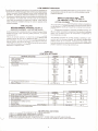
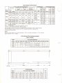
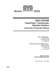
ELECTRICAL DATA 60HZ.
Model
ACWC
160SC
Wire Size•
Size 3
Amps'
Name
Circuit Circuit Circuit Circuit Circuit Circuit
Plate
Range
1'
1'
1'
2'
2'
2'
208-230 187-253
400
322
700
460
450
600
460
414-506
400
400
326
208-230 187-253
335
468
450
400
600
414-506
-
350
400
-
500
Qty.
H.P.
Type
Start
(3)60
ATL"
IJ.!.@_
(2)75
IJ.!.@_
750
185SC
460
Full
Locked
Load
Amps
Each
13.2
6.6
Rotor
Amps
Each
92.0
46.0
13.2
92 .0
Rated Locked
&uggoatod
Max. Fuoo
Min. Clroult
CONDENSER FANS
COMPRESSORS
TOTAL UNIT CHARACTERISTICS
VOLTAC:E
-
ATL"
Rotor
Amps
Each
1228
491
Load
Amps
Each
205
90
205
208
90
98
208
98
205
90
90
Phase
3
1228
1415
491
562
1415
562
1228
491
491
(2)75
208-230 187-253
500
750
339
468
500
600
200SC
(3)75
ATL "
460
414-506
500
358
450
208-230 187-253
501
700
900 v 900/
501
700
460
414-506
222
222
300
300
0000
0000
(4)60
215SC
ATL"
460 5
414-506
420
500
600
"ATL- Across The Line
'208-230 voltage requires two field wiring supplies (circuits).
' Minimum circuit ampacity is per N.E.C. Section 430-24.
3
Use time delay (dual element) fuses only. Suggested fuse sizes based on N.E.C. Section 440-22.
•Wire size based on copper conductors with 75° C. insulation per N.E.C . Table #31 0.16.
5 Single point power terminals
6.6
46.0
13.2
6.6
13.2
6.6
6.6
92.0
46.0
92.0
46.0
46.0
3
3
3
'
NOTE:
Maximum inrush amps is L.R .A. of lag compressor+ R.L.A. of all other compressors+ F.L.A. of all fans.
Lag Compressor: 75 H.P. on 185SC.
COOLER WATER PRESSURE DROP
(Feet of Water)
Model
GALLONS PER MINUTE
ACWC
320
340
360
380
400
420
160SC
12.0
13.7
15.4
17.1
18.8
20.6
10.6
11.9
13.1
14.3
15.7
17.1
13.1
14.3
15.7
17.1
11.1
12.2
13.3
14.4
15.5
185SC
200SC
215SC
---
-
-
-
-
-
440
-
460
480
500
520
-
-
-
-
-
18.6
20.2
-
18.6
20.2
-
-
540
560
-
-
-
-
16..Z_ _1_7 . ~
580
19.4 20.8
01
Q3
Qs
7L51
()2
1}4
Qs
slJl
6~~~-
~
138Y,
+
8
~
107Y,
LOADING (LBS.)
Dim.
LOCATION POINT NUMBER
Model
ACWC
1
2
3
4
5
6
7
8
160SC
2120
2120
2120
2120
1830
1830
1510
1510
74
185SC
2280
2280
2280
2280
1960
1960
1630
1630
129
8
200SC
2340
2340
2340
2340
2010
2010
1670
1670
129
215SC
2330
2330
2330
2330
2150
2150
2150
2150
129
18
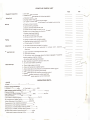
START-UP CHECK LIST
YES
NO
a. Unit damaged on arrival
Equipment Inspection:
~
b. Material received agrees with sh ipping papers
I
""
a. Vibration isolator used
Setting Unit:
b. Spring isolator adjusted for equal height
c . If rubber-in-shear isolators are used, is unit leveled by shimming
Wiring:
i
a. Power wiring complete
b. Control wiring complete
c. Electric service adequate for load
d . Power source voltage correct for motor(s) used
e. Motor circuit has proper size fusetrons
f. System wired per diagram
I'
g. All lead connections tight
h. Wiring complies with local codes
•.
a. Piping complies with applicable codes
Piping:
b. External piping independently supported
c. Chilled water lines insulated
a. All belts adjusted and checked for tension
Alignment:
b . All pulleys checked and adjusted for proper pitch , tightness and
alignment
a. Open compressor discharge service valve
Before Start-Up:
b. Open liquid valve(s)
c . Open suction , and discharge valves to pressure gauges (if supplied)
d . Check rotation of all fan motors
e. All motors and bearings lubricated
g. Start auxiliary equipment (pumps, fans , etc.)
h. Is crankcase heater operating?
a. Check high pressure control
After Start-Up:
b. Check oil temperature safety switch
-
c. Check and adjust low pressure or temperature freeze control
d. Check and adjust operating thermostat
e. Check and adjust low pressure operating control
f. Check and adjust expansion valve superheat
g. Check and adjust capacity control thermostat
OPERATING DATA
CHILLER
Voltage: L-1
L-2
L-3 _ _ __
Pressure Gauge Readings:
a. Suction
psig
b. Discharge
High pressure switch setting: (Cut-In)
Checked Setting
Yes
Yes
Low Pressure Freeze Control
- - - - psig (Out)
psig
- - - - psig (Out)
No
Low Pressure Switch Setting: (Cut-In)
Checked Setting
psig
psig
No
Cut In
Cut Out
Oil Temperature Safety Switch
Cut Out
If Star-Delta start, time delay is
seconds.
Temperature of air entering condenser
Temperature of air leaving condenser
oF.
oF.
Temperature of chilled water entering chiller
oF.
Temperature of water (chilled) leaving chiller
Chilled water pressure entering chiller
Chilled water pressure leaving chiller
oF.
psig
psig
..,._._..