1
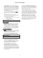
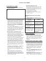
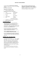
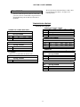
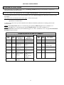
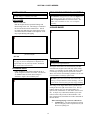
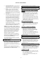
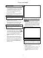
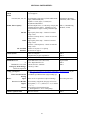
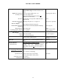
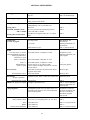
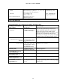
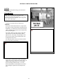
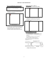
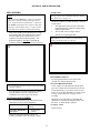
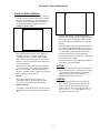
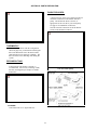
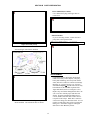
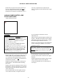
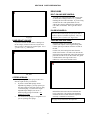
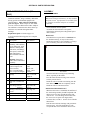
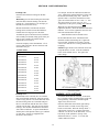
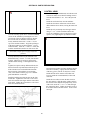
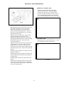
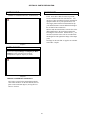
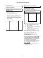
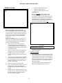
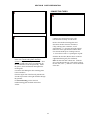
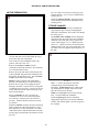
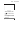
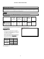
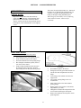
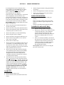
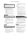
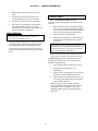
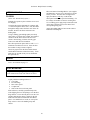
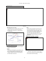
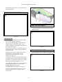
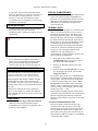
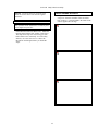
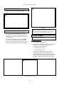
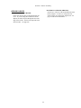
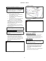
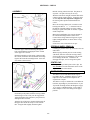
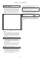
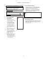
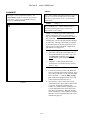
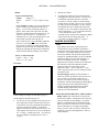
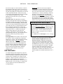
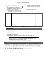
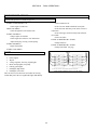
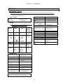
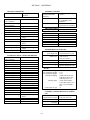
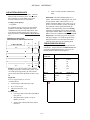
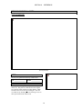
SECTION F -MECHANICAL COMPONENTS Slip the aluminum spacer between the outside of the trailing arm bushing and the chassis bracket. See the illustration above. Slide the 1/2" x 3" bolt through the flat washer, upper hole in the bracket, spacer and trailing arm bush, engaging the (locking) threads in the chassis. No lock-washer is necessary. Move to the trailing arm on the other side of the car. Sight through the hole in the chassis and determine whether the length of the trailing arm will have to be adjusted. Screw the trailing arm in or out on the rod-end as necessary. Secure the cable to the outside of the driveshaft hoop with a tie-wrap. Adjustment Rotate both the rod ends on the trailing arms all the way in at the top and tighten the jam nuts. Fully release the handbrake lever. Adjust the cable length by screwing the threaded end into the block to a point just short of where the handbrake operating levers on the calipers begin to move. Check the adjustment by pressing each operating lever at the same time towards the calipers. While doing this, observe the levers of the compensator on the cage - if they move noticeably, then the cable is too tight. To prevent binding, some slack should be obvious. Connect the brake flex-line to the bracket on the chassis. Check that the cable will not come in contact with the driveshaft at any time. If the assembly does not line up perfectly, pry or pull on the hub carrier to shift things around while installing the spacer and bolt. If the holes do not exactly line up, grinding a taper on the bolt may make it easier to get the threads to start. Torque the bolts on both sides to 45 lb-ft. Tighten the upper pivot bolts to 90 lb-ft. ANTI-SWAY BAR HANDBRAKE JAGUAR SUSPENSION Bolt the handbrake lever to the bracket on the 5 chassis with /16"USS bolts and lock washers. The 3/4" rear anti-sway bar mounts on the extensions of the rear crossmember just in front of the rear subframe ERA COMPENSATOR Attach the other end of the cable to the compensator lever on the suspension cage as shown above Slip the cable into the slot in the block attached to the lower lever of the compensator. Screw the threaded end of the cable into the hole in the block. Attach the bracket on the cable end to the other lever of the compensator. Do not tighten the lock nut. d\rswayb 5 The chassis is threaded for /16" USS bolts. If you meet resistance when installing the bolts, chase the threads in the chassis. A broken bolt inside the frame is difficult to fix. 76