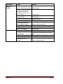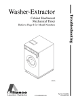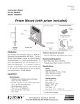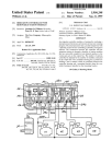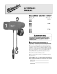
1
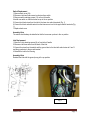
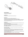
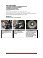
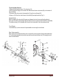
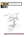
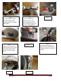
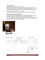
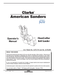
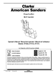
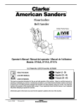
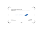
MODELS: 07129A, 07111A, 07117A, 07104A
56043144
Page 1
Switch Replacement
1-Remove back cover (24)
2-Disconnect inlet and interconnect cord wires from switch
3-Remove switch retaining screws (13) on front of handle
4-Install new switch so that the levers are up in the on position
5-Connect two black wires from the inlet to the lower two switch terminals (Fig. 1)
6-Connect the black and white wires from the interconnect cord to the upper switch terminals (Fig.
1)
7-Replace back cover
Assembly Hints
The switch should always be installed so that the levers are up when in the on position
Inlet Replacement
1-Remove 3 inlet retaining screws (9) on front side of handle
2-Disconnect all three wires from the back of the inlet
3-Connect the wires from the switch and the ground wire to the inlet with switch wires at X and Y
and the ground wire to the ground terminal
4-Reinstall the inlet in the housing
Assembly Hints
Reinstall the inlet with the ground prong in the up position
Fig. 1
56043144
Page 2
Drum Pulley Removal
1-Remove the pulley retaining nut (3)
2-Use gear puller to remove pulley
Assembly Hints
Install pulley with the long side of the hub in toward the drum
Drum Removal
1-Remove drum cover (4) to reveal the drum retaining nut (3).
2-Hold pulley with the two flats on the hub and remove the drum retaining nut
3-Pull drum using a specialty drum puller (Fig. 2) or gear puller (Fig. 3)utilizing the vent holes in the
end of the drum (Do not push the drum off by prying from the back. This will damage the rubber
and cause it to separate from the core.)
Assembly Hints
It is easier to push the drum on the shaft and then install the key rather than installing the key in the
shaft and pushing the drum over it
Always turn the drum retaining washer (2) over when reinstalling it
Be sure felt seals are installed in the inside of the drum to prevent dust build up which will cause
vibration leading to chatter (Fig.4)
When installing a new drum the drum must be trued or dressed to match it to the machine.
Drum truing or dressing
1-Glue or tape a piece of 80 or 100 grit paper to a very flat surface. Use a thick piece of metal or a
granite surface plate if possible.
2-Position the machine so that all wheels are on the flat surface and the drum is over the paper.
3-Slowly lower the drum to the paper while holding the feathering handle to allow only a small
amount of pressure between the drum and paper
4-Hold the machine steady in this position for 10 to 30 seconds and then use a compressor to blow
out the loose rubber before cooling
Repeat the process if necessary to prevent chatter or vibration when sanding.
56043144
Page 3
Arbor and Bearings assembly
1-Remove arbor retaining bolts (36) located behind the drum pulley
2-Pull assembly out of the frame from the left side
3-Press shaft out from the pulley end
4-Remove bearings from shaft and carrier
Reassembly
1-Press the outer bearing (35) in the carrier using the outer race only
2-Press the inner bearing (31) on the arbor shaft (32) using the inner race only
3-Press the shaft and inner bearing assembly into the carrier assembly by pressing on both races
of the inner bearing while supporting both races of the outer bearing
Assembly Hints
Use Loctite on the outer races of both bearings.
Fig. 2
Specialty drum pullers are
available for removing the
drum.
56043144
Fig. 3
A two or three jaw gear
puller can be used to remove
the drum.
Fig. 4
Felt seals (part # 30675A) are
used to prevent dust build up
in the drum. Machines
produced prior to July 2005
do not have the seals but they
can easily be added.
Page 4
Fan Assembly Removal and Repair
1-Remove belt guard
2-Remove three fan assembly retaining bolts (28)
3-Remove complete fan assembly
4-Remove the pulley retaining nut (24)
5-Pulley should pry off
6-Remove fan retaining nut (6) (Left hand threaded)
7-Fan should pry off
8-Remove both keys and spacer
9-Press fan shaft (35) out from pulley side
10-Remove bearings from shaft and housing
Reassembly
1-Press the 902567 (smaller) bearing on the fan end of shaft using the inner race only
2-Press the 51111A (larger) bearing into the pulley side of the housing and install the retaining ring
3-Press the shaft and bearing assembly into the housing and bearing assembly using the inner and
outer race of the fan bearing while supporting the inner race of the pulley side bearing
4-Reinstall fan and pulley
Assembly Hints
Fan spacer is installed with the wide flange toward the fan
The pulley is installed with the long hub side toward the bearing
The fan and pulley keys are interchangeable
Fan retaining nut is left hand threaded
If the fan doesn't spin freely after assembly - gently tap each end of the shaft to free the bearings
56043144
Page 5
Truck Assembly Removal
1-Remove drum pressure lever (13) and spring (14)
2-With the machine lying on the access door side loosen the two set screws (52) in the bottom of
the truck frame
3-Disconnect the drum control rod assembly (3) from the truck frame (55)
4-Screw a 1/4-20 bolt into the left end of the shaft (58) and pull shaft out (Fig. 5)
Assembly Hints
Both the rubber (63) and metal (45) spacer go between the truck frame and leveling bracket
If the eye bolt (40) is removed from the truck frame be sure to measure the threads for reassembly
The tension spring (14) is installed with the short end connected to the drum pressure lever
Truck Wheels
Truck wheels (51) can be removed & replaced without removing the truck frame
Rear Caster assembly
Rear caster and pivot axle assembly can be removed by removing the nut below the handle base
(17) or the lower assembly only can be removed by removing the lower nut (27) leaving the pivot
axle in the mainframe.
56043144
Page 6
Fig. 5
Using a 1/4-20 bolt threaded into the shaft will prevent
damage to the shaft surface when removing the shaft
56043144
Page 7
Tensioner Assembly Removal and Disassembly
1-Remove paper tensioning handle (34)
2-Remove three tensioner mounting bolts from left side of frame
3-Pull complete tensioner from paper access door side
4-Remove top roller assembly
5-With the tensioner in the compressed position use a C-clamp or bar clamp to compress the
tensioner spring (Fig. 6)
6-Remove upper link arm bolts (11)
7-Release clamp to separate the support (29) and carriage (18)
8-Remove Bolt from upper and lower rod ends (24) and (33)
9-Remove the draw lever pivot bolt (30)
10-Bring the draw lever out through the top of the support
Upper roller bearings
1-Remove snap (8) ring from short side of shaft (15) and drive shaft through from this end
2-remove bearings (9) from shaft and roller
3-Press new bearing on long end of shaft using inner race only
4-Install inside bearing in roller (Should be a slip fit)
5-Press shaft and bearing assembly into the roller and bearing assembly using only the inner
race of each bearing. (use Loctite on the outer races of both bearings)
Guide roller Bearings
Guide rollers are not serviceable and should be replaced as complete assemblies
Assembly Hints
If replacing the support (29) add or remove spacers (37) as needed
If replacing the rod ends (25) mark the center of the all thread (31) to make sure there is equal
engagement in both rod ends (Fig 7)
The gap between the rod ends should be approx. 3/8 (Fig 7)so that the single end on the draw (6)
lever just contacts the lower side of the support (29) when compressed (Fig 8) and the carriage
protrudes through the support approx. 1/16 (Fig 9)
Check to make sure the outer arms of the draw lever 9 are parallel (Fig 10) Draw levers prior to
2007 were soft steel and prone to bending
Fit between carriage and support must be free but not overly loose
Do not use lubricant other than aerosol Teflon on any of the moving parts
Machines produced before 2009 do not have the stainless shims in the support or carriage and
shims can not be added without replacing the support and carriage
Make sure the metal wave washers (14) are installed between the link arms and carriage (Fig 11)
Upper link arm bolts (11) will break easily if over tightened
One to three threads of the tracking adjustment screw (17) exposed through the underside of the
carriage (18) is a rough starting adjustment (Fig. 12)
Rubber boot (39) most be glued to the carriage and wire tied to the support to seal out dust
56043144
Page 8
Fig. 6
A clamp should be used to
hold the tensioner in the
compressed position during
disassembly
Fig. 9
If shaft is not at least flush
with the bottom of the casting
when compressed it will be
difficult to install sanding
paper
Fig. 12
56043144
Fig. 7
Center of rod has been
marked to show equal
thread engagement in the
two rod ends and gap is set
at 3/8 as a starting point.
Fig. 10
Fig. 8
Fig. 11
Washer must be in place to
prevent the shoulder bolt from
compressing into to aluminum
carriage
Fig. 13
Page 9
Testing the Capacitors
1-Disconnect all wires from the capacitor to be tested
2-With an insulated screwdriver short the terminals on the capacitor together to discharge it
3-With a multimeter set to the ohm setting attach one probe to each terminal (Fig. 14). If the
capacitor is good the needle should move up momentarily and then fall back to zero. You can
repeat the test by reversing the leads on the terminals.
If the needle does not move or moves up and does not fall back the capacitor is defective.
Testing the electronic start switch (SINPAC)
With a multimeter set to the ohm setting check the resistance between terminal 2 and 3. If the
resistance is less than 500K the switch has been shorted and must be replaced.
It's possible for a defective start switch to pass this test and still not function but further testing
requires specialty tooling. If the start switch passes this test and the motor shakes and will not
come up to speed the start switch is most likely defective.
Fig. 14
56043144
Page 10
Symptom
Cause
Repair
No power
Defective switch
Defective start switch (SINPAC Switch)
Defective start or run capacitor.
Poor connections
Defective motor
Check power supply and connections
Replace switch
Replace start switch
Replace defective capacitor
Check connections
Replace motor
Low voltage from excessive length,
undersize extension cord, or poor
connection
Defective run capacitor
Defective motor
Locate power source nearer to work site or
use a Voltage Booster. Check
connections.
Replace capacitor
Replace motor
Defective start switch (SINPAC Switch)
Replace start switch
Leveling out of adjustment
Readjust Level
Chatter
Paper tracking out of adjustment
Sanding in wrong direction
Damaged wheel or rear castor pivot rod
Drum damaged or out of round
Adjust tracking
Sand from left to right
Replace damaged wheel or pivot rod
Dress or replace drum
Clean drum
Waves
Excessive buildup of dust in the drum
Vibration from damaged or worn bearing
or belt
Defective sanding paper
Sub floor loose or not installed properly
Debris on wheels
Flat spot on wheels
Sub floor loose or not installed properly
Replace wheels
Repair sub floor
Improve smoothness of starting and
stopping or reduce sanding pressure
Motor will not
start.
Motor runs
sluggishly
Motor shakes
and will not
come up to
speed
Uneven cut /
lines in floor.
(Lines running
with the
direction of
sanding)
(Less than 2
inches between
marks.)
(2 inches or more
between marks)
Excessive stop and start marks
56043144
Replace worn or damaged bearing or belt
Replace paper
Repair sub floor
Clean or replace wheels
Page 11
Symptom
Paper not
tracking
Cause
Repair
Tensioner not adjusted properly
Paper not tensioned
Adjust tensioner
(If machine has been ran with the
paper untensioned there will be
noticeable paper cut marks on the
upper rod end) (Fig 13)
Poor dust pick-up
56043144
Excessive buildup of dust
around tensioner
Worn upper roller or guide roller
Draw lever damaged/bent
Excessive play between the
upper carriage and support
Drum damaged or out of round
Leveling out of adjustment
Defective sanding paper
Dust bag is over 1/3 full
Tension paper
Clean tensioner
Replace worn roller
Replace draw lever
Replace tensioner assembly
Dress or replace drum
Readjust level
Replace paper
Empty bag
Shake debris from bag and wash or replace
Dust bag is dirty
bag
Dust shoe is improperly adjusted Readjust dust shoe
Dust chute is obstructed
Remove dust shoe and clear throat
Fan belt loose, worn or
damaged
Tighten or replace fan belt
Page 12
14600 21st Avenue North
Plymouth, MN 55447-3408
www.clarkeus.com
Phone: 800-253-0367
Fax:
800-825-2753
©2010 Nilfisk-Advance, Inc.
A Nilfisk-Advance Brand