1
HumaStar 600
| User Manual
Cat No. 16660/001
REVISION LIST OF THE MANUAL
Rev. /DATE.
REVISION DESCRIPTION
01/2007-09
First edition
02/2007-11
Correction of typing errors
03/2008-03
New features of SW 1.7.1 implemented
04/2008-10
New features of SW 1.7.3 implemented
(calibration status, reagent status, ISE module update)
05/2009-01
Typing errors corrected
06/2010-05
New features of SW 1.8.1 implemented
(clot detection, power user, wear, BCR for controls and standards)
07/2011-06
Update for software 1.8.1 r2011.05.30
08/2011-09
Correction dimension
SYSTEM VERSION
COPYRIGHT
Copyright 2010, Human GmbH, Wiesbaden, Germany. All rights reserved.
No part of this documentation may be reproduced in any form, nor processed, copied or
distributed by means of electronic systems, without prior permission of Human GmbH in
writing. Since all precautionary measures were taken into account in producing these operating
instructions, the manufacturer accepts no responsibility for any errors or omissions. This
includes any liability for damage that could arise from possible incorrect operation based on this
information. Subject to changes without notice as result of technical development.
SERVICE UND SUPPORT
CONTENTS
TABLE OF CONTENTS
1 SAFETY INSTRUCTIONS
1.1 INTRODUCTION
7
7
1.2 USER WARRANTY
7
1.3 INTENDED USE OF THE INSTRUMENT [IVD]
8
1.4 GENERAL SAFETY WARNINGS
8
1.5 DISPOSAL MANAGEMENT CONCEPT
9
1.6 INSTRUMENT DISINFECTION
1.7 BIOHAZARD WARNING
9
10
2 INTRODUCTION
13
3 SYSTEM DESCRIPTION
15
3.1 UNPACKING
15
3.2 INSTALLATION
15
3.2.1
3.2.2
3.2.3
3.2.4
3.2.5
3.2.6
3.2.7
Installation Requirements
Electrical connections
Hydraulics
Handling of biological fluids
Computer setup
Parameters
Tools
3.3 PARTS OF THE INSTRUMENT
3.3.1
3.3.2
3.3.3
3.3.4
3.3.5
3.3.6
Front view
Top View
Left side
Samples and sample sectors
Reagents
Cuvettes
3.4 SOFTWARE FUNCTIONS OVERVIEW
3.4.1
3.4.2
3.4.3
3.4.4
Levels of access
Other functions included in Data menu
Main Screen
Relevant screens
15
16
16
17
18
19
22
25
25
25
26
26
27
27
27
28
29
30
33
4 GET READY FOR OPERATION
37
4.1 AUTOMATIC OPERATION
37
4.1.1 Clot detector
38
5 ROUTINE UTILIZATION
5.1 REAGENTS
5.1.1
5.1.2
5.1.3
5.1.4
5.1.5
5.1.6
Reagent tray
Loading bar-coded reagents
Loading non bar-coded reagents and solutions
Removing reagents and solutions
Refilling reagent bottles (only for open channels)
Method assignment to trays
5.2 SAMPLES
5.2.1 Working with patients
5.2.2 Defining sample data and tests
5.2.3 Removing a sample
5.2.4 Removing tests
5.2.5 Copy data
5.2.6 Loading samples
5.2.7 Removing a sample
5.2.8 Placing a sector on the tray
5.2.9 Removing a sector
5.2.10 Loading a STAT
5.2.11 Reports on load and use
5.3 TEST RESULTS
5.3.1
5.3.2
5.3.3
5.3.4
Acceptance of Results
Reflex Tests
Printout of results
Cuvette
5.4 CALIBRATION
5.4.1
5.4.2
5.4.3
5.4.4
5.4.5
Calibrator sets
Requesting a calibration
Ordering a calibration
Calibration acceptance
Automatic calibration
39
39
39
40
40
41
42
42
43
44
44
47
47
47
48
49
49
49
50
50
51
52
53
53
53
54
54
56
56
57
58
5.5 BLANKS
58
5.6 QUALITY CONTROL
59
5.6.1
5.6.2
5.6.3
5.6.4
Creating a control set
Requesting a control
Processing a control
Processed controls. Statistics
5.7 TWIN QC
5.7.1 QC scheduler
60
60
62
62
63
64
CONTENTS
5.8 WORKING WITH LIS
5.8.1 ASTM structure of messages.
5.8.2 Communication examples
65
66
70
5.9 DEFINITION AND USE OF SAMPLE PROFILES
71
5.10 DEFINING A SAMPLE PROFILE
71
6 DEFINITION OF METHODS
6.1 MANAGEMENT
6.1.1 Creating or editing a method
6.2 METHOD PARAMETERS
6.2.1
6.2.2
6.2.3
6.2.4
6.2.5
6.2.6
6.2.7
6.2.8
6.2.9
Common parameters
Main Page
Quantitative
Limits
Reference classes
Advanced features
Consumption
Reagent substitution
Quantitative
73
73
74
74
74
75
76
77
78
78
79
80
81
6.3 ACCESSORIES: SOLUTION AND OPTIONS
82
6.4 CALCULATED METHODS
83
6.5 ISE METHODS
83
6.6 EXTERNAL METHODS
83
6.7 UNITS AND LIMITS
84
6.8 UNITS CONVERSION (FOR SERVICE ONLY)
84
6.9 DEVELOPEMENT OF A METHOD
86
7 ISE MODULE CAT.-NO. 16663
87
7.1 OVERVIEW
87
7.2 PRINCIPLES OF MEASUREMENT
88
7.3 TECHNICAL SPECIFICATIONS
90
7.4 REAGENTS (ISE PACK)
90
7.4.1 Composition
7.4.2 Reagent installation
7.4.3 Removal
91
92
93
7.5 METHODS
93
7.6 OPERATION
94
7.6.1 Manual operation
7.6.2 Automatic operation
94
95
7.7 MAINTENANCE OPERATIONS
96
7.8 ERRORS
96
8 MAINTENANCE
99
8.1 COUNTERS
8.2 DAILY CARE AND MAINTENANCE
8.2.1
8.2.2
8.2.3
8.2.4
8.2.5
ISE priming serum
Inspection and cleaning of probe
Hydraulic testing
Replacement and control of wash and cleaning solutions
Intensive cuvette cleaning
99
100
100
100
100
101
101
8.3 WEEKLY MAINTENANCE ROUTINE
102
8.3.1 Intensive washer cleaning
102
8.4 MONTHLY MAINTENANCE RECOMMENDATIONS
8.4.1 Washer volume calibration
8.4.2 Other tasks
103
103
103
8.5 MAINTENANCE ON DEMAND
103
8.6 LAMP REPLACEMENT
103
8.7 PUMP TUBE REPLACEMENT
104
8.8 DRYER BLOCK REPLACEMENT
105
8.9 SYRINGE REPLACEMENT
105
8.10 ISE MAINTENANCE
106
8.10.1 Electrode removal or cleaning
8.11 PINCH VALVE UNCLOGGING
8.11.1 Pump tubing replacement
8.11.2 Electrode recovery
8.11.3 Sodium electrode conditioning
9 TROUBLESHOOTING
106
108
109
109
110
111
9.1 MESSAGES AND WARNINGS
111
9.2 VISIBLE FAULTS
111
9.2.1 General faults
9.2.2 Automatic cuvette washer malfunctioning
9.2.3 Measurement inconsistencies
111
112
112
5
10 SYSTEM TESTS
117
10.1 TEMPERATURE
117
10.2 STRAY LIGHT
117
10.3 NOISE
117
10.4 STABILITY
118
10.5 TIP PUMP
118
10.6 LEVEL DETECTION
118
10.7 WASHER HYDRAULICS
118
10.8 WASHER
119
10.9 DILUTION
119
10.10 PHOTOMETER LINEARITY
120
10.11 DILUTER LINEARITY
120
10.12 LEVEL DETECTION
120
10.13 CHEMISTRY ANALYSIS
120
10.14 CLOT DETECTOR
121
11 BACKGROUND
11.1 METHODS TYPES AND CALCULATION
11.1.1
11.1.2
11.1.3
11.1.4
Single point end point
Two point end point
Fixed Point
Kinetics
12 APPENDIX
123
123
123
123
124
125
127
12.1 TECHNICAL SPECIFICATION
127
12.2 CALIBRATION
128
12.2.1 Mechanical calibration
12.2.2 Photometer Calibration
12.2.3 Reagent bottles
128
12.3 BARCODE READER OPERATION
137
12.3.1
12.3.2
12.3.3
12.3.4
Definitions
Usage of barcode features
Parameters for barcode reader
Implementation of barcodes
12.4 SERVICE OPTIONS
12.4.1 Lamp intensity
12.4.2 Filter wheel
12.4.3 Other Servicing options
136
137
137
137
138
139
140
140
140
141
6
HumaStar 600 | User manual
SAFETY INSTRUCTIONS
1 SAFETY INSTRUCTIONS
1.1 Introduction
This manual is considered as a part of the instrument; it has to be at the
operator’s hand as well as at the maintenance operator’s availability. For
accurate installation, use and maintenance, please read the following
instructions carefully. In order to avoid instrument damage or personal
injury, carefully read the ”GENERAL SAFETY WARNINGS”, describing the suitable
operating procedures. In case of breakdowns or any troubles with the
instrument, apply to the local Technical Service.
1.2 User Warranty
HUMAN warrants that instruments sold by one of its authorised
representatives shall be free of any defect in material or workmanship,
provided that this warranty shall apply only to defects which become
apparent within one year from the date of delivery of the new instrument to the
purchaser.
The HUMAN representative shall replace or repair any defective item at no
charge, except for transportation expenses to the point of repair.
This warranty excludes the HUMAN representative from liability to replace
any item considered as expendable in the course of normal usage, e.g.: lamps,
valves, syringes, glassware, fuses, diskettes, tubing etc.
The HUMAN representative shall be relieved of any liability under this warranty
if the product is not used in accordance with the manufacturer‘s instructions,
altered in any way not specified by HUMAN, not regularly maintained, used with
equipment not approved by HUMAN or used for purposes for which it was not
designed.
HUMAN shall be relieved of any obligation under this warranty, unless a
completed installation / warranty registration form is received by HUMAN
within 15 days of installation of this product.
This warranty does not apply to damages incurred in shipment of goods. Any damage so incurred shall be reported to the freight carrier for settlement or claim.
7
8
1.3 Intended Use of the Instrument [IVD]
The instrument is intended for in vitro diagnostic application by
professional users. It has to be used for the expected purposes and in
perfect technical conditions, by qualified personnel, in working conditions and
maintenance operations as described in this manual, according to the
GENERAL SAFETY WARNINGS. This manual contains instructions for
professional qualified operators.
1.4 General Safety Warnings
Use only chemical reagents and accessories specified and supplied by
HUMAN and/or mentioned in this manual. Place the product so that it has proper
ventilation.
The instrument should be installed on a stationary flat working surface, free
from vibrations.
Do not operate in area with excessive dust.
Work at room temperature and humidity, according to the specifications listed
in this manual.
Do not operate this instrument with covers and panels removed.
Only use the power cord specified for this product, with the grounding
conductor of the power cord connected to earth ground.
Use only the fuse type and rating specified by the manufacturer for this instrument, use of fuses with improper ratings may pose electrical and fire hazards.
To avoid fire or shock hazard, observe all ratings and markings on the
instrument.
Do not power the instrument in potentially explosive environment or at risk of
fire.
Prior to cleaning and/or maintaining the instrument, switch off the instrument
and remove the power cord.
For cleaning use only materials specified in this manual, otherwise parts may
become damaged. It is recommended always to wear protective apparel and
eye protection while using this instrument. Respective warning symbols, if
appearing in this manual, should be carefully considered.
HumaStar 600 | User manual
SAFETY INSTRUCTIONS
1.5 Disposal Management Concept
The currently valid local regulations governing disposal must be observed. It is in
the responsibility of the user to arrange proper disposal of the individual
components.
All parts which may comprise potentially infectious materials have to be
disinfected by suitable validated procedures (autoclaving, chemical treatment)
prior to disposal. Applicable local regulations for disposal have to be carefully
observed.
The instruments and electronic accessories (without batteries, power packs etc.)
must be disposed off according to the regulations for the disposal of electronic
components.
Batteries, power packs and similar power source have to be dismounted from
electric/electronic parts and disposed off in accordance with applicable local
regulations.
1.6 Instrument Disinfection
Analytical instruments for in vitro diagnostic involve the handling of human
samples and controls which should be considered at least potentially infectious.
Therefore every part and accessory of the respective instrument which may have
come into contact with such samples must equally be considered as potentially
infectious.
Before doing any servicing on the instrument it is very important to
thoroughly disinfect all possibly contaminated parts. Before the instrument is
removed from the laboratory for disposal or servicing, it must be
decontaminated. Decontamination should be performed by authorised welltrained personnel only, observing all necessary safety precautions. Instruments to
be returned have to be accompanied by a decontamination certificate completed
by the responsible laboratory manager. If a decontamination certificate is not
supplied, the returning laboratory will be responsible for charges resulting from
non-acceptance of the instrument by the servicing centre, or from authority’s
interventions.
9
10
1.7 Biohazard warning
Analytical instruments for in vitro diagnostic application involve the handling of
human samples and controls which should be considered at least potentially infectious. Therefore every part and accessory of the respective instrument which
may have come into contact with such samples must equally be considered as
potentially infectious.
For safety reasons, we have labeled instruments with the
„BIOHAZARD“ warning label below.
FIGURE 1
Biological Hazard Symbol
HumaStar 600 | User manual
SAFETY INSTRUCTIONS
Notes:
11
12
HumaStar 600 | User manual
INTRODUCTION
2 INTRODUCTION
The HumaStar 600 is a reliable in vitro diagnostic chemistry analyzer for
automatic testing of routine clinical chemistry tests and electrolytes.
Being real random access, this HumaStar 600 is the ideal solution for medium
to large size labs, with a throughput of more than 600 photometric tests/hour
(720 tests/hour with ISE).
Continuous process can be achieved as samples sectors can be loaded quickly
and simply allowing nonstop operation. Sectors can hold primary tubes and
small sample cups.
Refrigerated reagent tray can hold up to 48 different containers ranging from
20 to 70ml depending on configuration.
The optional ISE unit gets electrochemical measurement of Na+, K+ and Clelectrolytes with automatic urine sample dilution. The instrument is
controlled by a PC workstation that has graphical -user friendly- interface software. The software provides total control over the analyzing
process and gives easy access to advanced statistical functions and
reports. Versatile method setup comprises end point, fixed point, kinetics, ISE,
coagulation, calculated and externals. Optional features include:
Flexible pre- and post washing for each test to prevent carryover.
Auto rerun with automatic dilution of samples which are out of linear range.
Automatically duplicate for result confirmation
Extra volume dispensing of water or reagent to improve accuracy.
Reagent integrity check for safe operation.
Automatic predilution for calibrators, controls, blanks and samples to fit any
method insert.
Curve and linear calibration with unlimited number of standards for highest
accuracy.
Other features include:
Onboard sample and reagent bar code reading assure positive identification.
Capacity sensor monitors sample and reagent volumes.
Instant mixing during dispense gives precise initial reaction time.
Automatic acceptance of calibrators, control and samples increase the walk
away time.
- Current activity monitor screen indicates to the operator when the routine
will be finished
- Clot detector
- Low water consumption.
13
14
HumaStar 600 | User manual
SYSTEM DESCRIPTION
15
3 SYSTEM DESCRIPTION
3.1 Unpacking
Remove all the parts from their package.
When unpacking the instrument, please make sure that the following items are
contained in the packing. In case of damage or missing item, please contact the
supplier immediately.
Quantity
1
2
2
1
1
2
2
1
5
1
1
Description
[REF]
Software CD
Reaction cuvettes (box of 1200)
Drying block kit
Reagent recipients with cap (x 30) vol. 70 ml
Reagent recipients with cap (x 30) vol. 30 ml
Peristaltic Pump tubing kit x 3
Sample tubes 13 mm. kit x 100
Halogen lamp 12V 20W
Sample Rack
Serial Cable
User Manual
16661
16661/1
16661/11
16661/2
16661/3
16661/4
16661/5
16661/7
16661/15
16661/16
16660/001
3.2 Installation
3.2.1 INSTALLATION REQUIREMENTS
Carefully read the safety instructions included in this manual.
Install the instrument on a hard floor with a resistance of at least 50 Kg/cm2;
use, if possible, ceramic or stone floor.
Avoid carpets or very soft rubber.
Mains should be close to the instrument (less than two meters) and must fulfill
local regulations.
Free access to main switch is required. A distance of 50 cm from the left side
of instrument to nearest table or wall is advisable. Right side must have a free
space of at least 30 cm for ventilation purposes.
Space must be empty over instrument to 2.10 m. Avoid using shelves, walls or
screens above instrument.
Instrument is mounted on wheels and can be moved towards the front for
servicing and cleaning purposes. Allow free space of about two times the
instrument depth.
TABLE 1
16
Instrument
Category
requires
connection.
is
Installation
II.
Instrument
protective
ground
Verify
ground
3.2.2 ELECTRICAL CONNECTIONS
Plug in the mains cord to a socket with ground connection. The power
requirements for the HumaStar 600 are as follows: 100~240 VAC, 50/60 Hz,
1000 VA maximum.
connection before installing the
instrument.
User must be warned about
the use of instrument under
abnormal grounding conditions.
Maximum voltage between ground and neutral lead: 0.5 volts.
There is a J9 serial port type RS232C connector in the rear part of the instrument
(see Figure 1 2 oben). Connect the HumaStar 600 to the computer serial port
using the provided cable. Tighten retaining screws.
It is advisable not to complete
installation under poor ground
3.2.3 HYDRAULICS
The waste deposit collects the drainage of the probe washing stations and
occasional waste from the dispensing stations and cuvette washers. Place the
emptied bottle in the correct location and orientation (see Figure 1 oben).
The washing solution is a dilution of 1 ml of additive (18981) per liter of DI water.
Place the 10 L reservoir with washing solution and connect the yellow coded level sensor tubing on the corresponding fitting in the stopper. Do the proper with
the two inlet transparent tubing for the washing solution.
Put the pump tubing of the washing pumps in place. Take out the plastic
protection tube (typically yellow) from the probe arm‘s vertical shaft before
operating.
conditions.
FIGURE 2
HumaStar 600 | User manual
SYSTEM DESCRIPTION
17
FIGURE 3
3.2.4 HANDLING OF BIOLOGICAL FLUIDS
Before connecting wash and drain lines, be sure to remember and understand
regulations and cautions about potentially dangerous biological fluids.
Keep in mind the following considerations:
1. Due to the presence of biological fluids, some instrument areas are
potentially dangerous. They are warned with the symbol
Dispensing tips, reaction cuvettes and drain fluid bottle are the most
endangered areas.
Never
dispose
potentially
dangerous fluids on public
drain system
18
1. Sample handling, drain fluid disposal and reaction cuvettes replacement
must be done with safety disposable gloves manufactured according local
regulations for biological fluids handling.
2. Drain fluid must be neutralized. The addition of 0,5 % Sodium Hypochlorite
is suggested.
3. Verify and use local regulations on discarding pathological fluids.
4. If instrument is to be translated to other location or stored for a long period,
perform at least 5 purge cycles, remove cleaning solution bottle and repeat
purge cycles until drain lines are empty. Neutralize and dispose drain fluid.
3.2.5 COMPUTER SETUP
Follow the instruction set of the computer‘s manufacturer to connect and
operate the computer system.
The minimum requirements for the computer are:
TABLE 2
Processor
Memory
Video adapter
Monitor
Display resolution
Colour quality
Hard drive
CD-RW CD Read/Write
USB port
Keyboard
Pointing device
Soundcard
Speakers
Network adapter
Serial Port
Operating system
3.0 GHz Intel Pentium 4
2 Gb DDRAM
64 Mb, AGP 2x
17“ (VIS 15.7“)
1024x768 (vertical refresh > 70 Hz)
16 bits
80 Gb EIDE ATA-100 7200 rpm
IDE 48/16/48 Speed
1.1 or 2.0
105-key Performance keyboard
PS2 or USB mouse
Integrated 16 bit (optional)
(optional)
Ethernet 10/100 Mbits
RS-232 serial port
MS-Windows XP or MS-Windows Vista.
Compatible printer
Any Windows™ compatible printer maybe installed .
LIS must be installed in a different computer connected through serial port.
The visual effects to best performance.
Change the setting of the operating system. Under properties Advanced
options visual effects select “Adjust for best performance”
HumaStar 600 | User manual
SYSTEM DESCRIPTION
19
Setting of the Anti Virus Software
We recommend the use of Anti Virus Software on the Personal Computer of the
HumaStar 600. The HumaStar 600 “Rayo” directory has to be excluded from the
scanning process. Please refer to the documentation of the Anti Virus Software
Don‘t use the predefined MS Windows XP and VISTA folders.
As a default setting MS Windows is using predefined folders. This user profiles
are located in Windows XP (C:\Documents and Settings) and in VISTA (C:\users).
This includes “My documents”, “Desktop”, “Favorites”, “My Music” etc. Big files
will reduce the computer performance.
Don‘t use predefined directories to store data. Move all files to other directories
(e.g. C:\documents).
The PC shall be used only for the operation of the instrument.
Any other programms besides the instrument software may cause instrument
malfunction and/or breakdown.
3.2.6 PARAMETERS
There are few parameters for software and instrument use accessible to
operator. They are located in
3.2.6.1 Software
Includes pages for communications, LIS and bar code reader.
FIGURE 4
20
General
FIGURE 5
1. Communications. Select serial port according to your computer setting and
specification. If setting is wrong, the HumaStar 600 temporarily checks for
other port; but if no ports are free, program might not work properly.
2. Language. Select among languages already set in the translator. Changes
will come into effect when program is closed and re-opened.
3. Historic. Defines size in days for samples and Controls.
4. Random access.
5. Coagulation. Enables/disables coagulation mode.
6. On-line printing. Enables printing; selector of printout of pending
acceptance samples and printout of manually accepted results7. Automatic. Selection of active warnings for removing and installation of
caps.
8. Automatic acceptance. The automatic acceptance can be conditioned or not
by the reference classes values. In other words, it can be programmed that
values within the reference class are automatically accepted and the others,
not.
9. ISE processing check can be enabled by default with a parameter.
10. The DI empty warning can stop dilutions if checked and issue warning but
continue, if not checked.
11. Patient window: selection of display.
Reagent integrity check: run the reagent integrity check at each start of
samples or only once a day.
12. Clot behavior: see section 4.1.1
HumaStar 600 | User manual
SYSTEM DESCRIPTION
BCR
13. BCR. Codes can be defined for sectors, samples and reagents. When
sectors are provided with bar code identification, it is not necessary to define
a number for sector loading.
14. Reagent configuration. Select setting according to your requirements. This
selector defines options for Method, bottle type, expiration date format and
starting position.
15. Sample configuration. This option enables the use of only a part of code,
starting from a given digit and taking a given length. If Id position is not
selected, all code digits are read.
LIMS
16. Enabled. Sets communication with host computer.
17. Options. Select parameters according to specifications of your LIMS provider.
3.2.6.2 Use
Use parameters are split in several sections: Cuvette absorbance limits, ISE and
definitions of sample vials.
1. Cuvette blanks. Includes upper and lower limits in cuvette testing. Tolerance
refers to the allowed absorbance variation after first reading.
2. ISE. User determines if he allows or avoids sample pre-wash. For details, see
Section 0
3. Sample vials. Two different sample vials can be defined. This feature is useful to define pediatric vials. Volume calculations require careful section
measurement for each defined vial.
3.2.6.3 Reports
This section allows sorting how methods are ordered in report and printout. Keys
Up and Down allow moving methods to different positions in the final printout.
3.2.6.4 Sector definition
Here user determines if a sector is defined as STAT or not. If so, all samples
loaded in the sector will be processed with priority over samples of other sectors.
Define a new sector with a number and assign the STAT condition, if required.
Be sure that number is not already defined in the column to the right. If so, first
delete definition and then re-enter new definition, including STAT condition.
21
22
3.2.7 TOOLS
Always end any modification
by pressing the ENTER key.
3.2.7.1 Translator
Translator operates on the language selected in Software parameters.
There are two basic ways of translating: translation control and
dictionary. To translate by translation control, place mouse pointer on the
screen and phrase whose translation must be modified; press keys
Shift + Control + C. The following screen will open:
Left column is the Instrument Internal Language. It is mostly English; second
and third column are the present translation, if any. Text may be local or global,
that is, can be used only in the selected position or used in different screens.
Modification can be local or global. Global modifications affects all entries of
the same text. In case of doubt, perform local modifications only.
Modifications take effect only when program is restarted. When a given
translation is empty, system will use Internal language, no matter which
language is selected.
For translation with Dictionary, select:
Maintenance > Tools > Translator.
When any entry is selected, upper window shows internal text and lower
window, the translation, if present.
Sorting can be performed by internal or by translation. There is also a built-in
search tool. Entries can be deleted by pressing the corresponding button.
3.2.7.2 Modify reports
Customized report can be modified at will by user in
Maintenance > Tools > Modify Report.
There are four bands that can be added or removed by use of the Add / Remove
option. They are: title, header, data and footer.
Title Band includes one option only: title caption. Select in the upper right
window the “txtCaption” option and press Edit. The New/ Edit Text screen will
show up:
HumaStar 600 | User manual
SYSTEM DESCRIPTION
23
FIGURE 6
Text, position, size, font can be modified in this screen.
FIGURE 7
Press on the “+” symbol in the header band and a complete listing of possible
fields will be displayed. There are two types of fields: DataText are the Results
written by instrument once a value is printed. They can be moved, eliminated,
changed font, etc. but its text is out of operator‘s control. There also Report
variables that can be added at this time. They include page numbering date and
time in different possible formats.
In the New/Edit Data Text, the Change button allows selecting the desired field
to be shown. The Texts are the true headers corresponding to the Data texts and
24
can be fully modified. When the Change button is pressed, the following screen
is seen:
FIGURE 8
As an example, the following report format is included in software. User can
experiment on adding, removing and modifying printed fields.
FIGURE 9
HumaStar 600 | User manual
SYSTEM DESCRIPTION
25
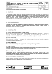
3.3 Parts of the Instrument
3.3.1 FRONT VIEW
FIGURE 10
Front View
1 On/Off switch
2
1
2 Cooling switch
3 Waste tank
4 Washing pumps
4
5 Front/Back dilutor
6 Wash water
3
5
6
6
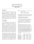
3.3.2 TOP VIEW
FIGURE 11
Top view
1
3
4
2
1 Back reaction tray
2 Front reaction tray
3 Reagent tray
4 Sample sectors
5 Front/back pipettors
6 ISE prime reservoir
5
26
3.3.3 LEFT SIDE
FIGURE 12
1 Service door for lamp
1
2 Electronics
2
3.3.4 SAMPLES AND SAMPLE SECTORS
Samples are loaded in a 19 positions sample sector. Continuous p-rocessing
is possible by the use of different bar-coded sample sectors, which the user
can insert or remove from sample tray during analysis. After loading the
sector, samples are immediately identified by direct barcode reading jointly with
sample sector type recognition. Five segments can be present simultaneously
in the sample tray, while up to 99 external (out of tray) sectors can be handled
by the system. STAT samples can be loaded in special high priority sectors to
be processed. Standard sector holds 19 bar-coded primary tubes or 19 non
bar-coded cups and primary tubes. Special sector for 16 mm external diameter
tubes is available upon request.
Sectors can hold:
- micro cup:
0.5 ml
- standard cup:
1.5 ml
- primary tube:
5 ml (13 x 75 mm)
7 ml (13 x 100 mm, 13 x 75 mm)
10 ml (16 x 100 mm)
FIGURE 13
Standard 19 positions bar-coded sector
HumaStar 600 | User manual
SYSTEM DESCRIPTION
27
3.3.5 REAGENTS
This HumaStar 600 has a cooled reagent tray where 20 ml, 40 ml and
70 ml containers can be placed. The reagent tray includes integrated barcode
reader for 24 inner and 24 outer positions. Inner positions can hold two reagents
in split containers increasing the total number of onboard reagents to 72 (not
available yet). Dilution as well as buffer solutions are also placed in the reagent
tray.
FIGURE 14
1
2
3
Reagent tray and different
containers positions
1 Inner position
2 Outer position
3 Split Containers (currently
not available)
3.3.6 CUVETTES
Samples and reagents are dispensed into a multiple cuvette strip. Each strip has
5 cuvettes. Reaction trays hold 16 cuvettes strips each, having the system a total
of 160 cuvettes.
FIGURE 15
Cuvettes strips
3.4 Software functions overview
The software offers complete functionality to control the instrument and
monitor the overall operation which includes: samples and patients
management, control reagents, program tests, calibration of methods, perform
QC tasks, reactions follow up, statistic on results, among others.
28
3.4.1 LEVELS OF ACCESS
System has different levels of access depending of the type of user:
Operator
- Normal user
- Power user
- Supervisor
- Service
Select in main menu:
FIGURE 16
Select Log as Power User, Supervisor or Service and introduce corresponding
Password.
FIGURE 17
Log Out option will return to the operator´s condition. Main menu allows
modifying Passwords. Normal User is the default condition. In that case, only
operation is possible. Power User can define control sets and calibration sets.
Several actions described in the present manual will be available to Supervisor
only. They will be indicated with the symbol:
HumaStar 600 | User manual
SYSTEM DESCRIPTION
29
For actions when use is defined as Service, please refer to the corresponding
Manual.
3.4.2 OTHER FUNCTIONS INCLUDED IN DATA MENU
With the Import function, operator can retrieve several configurations,
other than the software database (...\Program Folder\Database). Importable
information are, for instance; Methods, QC Sets, Calibrator Sets, Units
conversions and Translator information.
FIGURE 18
The Service Backup item allows the creation of an instrument image for
servicing purposes. The Reconnect option restarts the instrument hardware
operation.
30
3.4.3 MAIN SCREEN
1
10
FIGURE 19
Main Screen
2
9
3
1 Menu
2 Operator requests
8
4
3 Disable ISE
(if available)
4 System messages
5 System
7
5
information
6 Current activities
7 Reagent
6
Information
8 Status of selected
methods
9 Tests in progress
Main screen combines the information required for instrument operation,
allowing user to check for instrument status and intervention (when required) at a glance.
Quick keys menu provide direct access to the major program functions.
10 Quick keys
Main
review the information about current run.
Patients
set demographic data and relevant information.
Samples
define and order chemistry, ISE, coagulation and calculated tests.
Tests
review pending reactions and analysis results.
Reagent tray
graphically insert or remove reagents in tray.
HumaStar 600 | User manual
SYSTEM DESCRIPTION
31
32
Sample tray
load new samples and graphically insert or remove sample sectors in tray.
Reactions
graphically review cuvette usage and change cuvettes.
Calibrations
request or browse pending acceptance, historic and in use calibrations.
Quality Control
request or browse QC and handle statistical functions.
Methods
browse and edit definitions of methods.
BLK
Blanks
Definition, review and acceptance of reagent blanks.
Main operation control tool bar gives control over mayor automatic routine
operation. Use:
Initialize
to initialize all the instrument units to rest positions.
Start
to begin the routine operation.
Stop
to stop the routine operation.
Suspend and re-start dilutions.
Allows to momentarily stopping dilutions for sample and STAT
load.
The Running Options can be selected by operator according requirements which
depend on the moment and opportunity.
Non-stop operation: When this option is selected, the automatic cycle does
not finish and after sample process instrument is in stand-by condition. This
HumaStar 600 | User manual
SYSTEM DESCRIPTION
option is recommended when additional samples for processing are expected
soon. When daily work must finish, option must be de-selected.
For daily work end, deselect the option.
Process ISE assays: disable if ISE samples are not expected for the day. This
option will not be shown if ISE module is not enabled.
Process Coagulation assays: disable if coagulation samples are not expected for
the day.
The bar of requests to operator provide actions requested from instrument to
complete some operation such as confirmation of calibrations, confirmation on
sample results outside reference class limits, etc. Also, a tip cleaning request is
issued if previous cleaning cycle has not been completed.
Messages list registers most relevant notes and warnings the instrument
operation can generate such as running out of sample or out of reagent. Transmission and operating status displays communication condition between the
computer and the instrument (Connecting, Online or Offline and Operating).
Current activity and summary contain relevant information about in progress
system operations, phase of operation (Pre-automatic, automatic or postautomatic), next dispensing / reading operation and remaining readings and
dispenses.
Test in progress provide the lists of queued test for processing.
Reagent status report shows required reagent volumes to accomplish the
processing of the on-tray samples as well as reagent availability. With right
click in mouse, options about operations are shown. Information on missing
reagents and on missing calibration is also included.
General status bar shows context-sensitive help or information.
Menu bar gives quick and comprehensive access to most program functions
33
34
3.4.4 RELEVANT SCREENS
HumaStar 600 | User manual
From main menu it is possible to access the
reagent tray programming to place or remove
reagent or solutions.
The second reagent of a given double reagent
method will be marked with a dot.
Slide mouse over a reagent on the tray to
obtain details on the right panel regarding
reagent usage, available volume and pending
reactions. Alternative views on reagents and
calibration status are available.
FIGURE 20
Sample tray consists of five sectors of
19 samples each.
User can prepare and load additional sectors
while instrument is operating.
FIGURE 21
To locate a cuvette corresponding to a certain
reaction, click on the reaction tray graph.
Two buttons may be used to force a manual
wash of the cuvettes or assert the replacement
with new ones.
When this operation is performed motors
are disengaged for easier operation and
reconnected when done.
FIGURE 22
SYSTEM DESCRIPTION
FIGURE 23
35
Data such as patient name, sample type, MD,
diagnostic can be included.
Also, the assignment of samples to each patient
is performed.
For calculated methods, if more than
one sample is involved, all must be
assigned to the patient.
The patients window can also be accessed
directly from samples window.
FIGURE 24
Data from samples are added to this
identification screen: Id, type, collection date.
Also, tests and number of replicates are
incorporated.
This load can be performed method by method
or with the aid quick load and Profile screens.
Patients can be defined with button located to
the left of Patient Id.
FIGURE 25
Calibration by a single standard and multipoint
methods are carried out by calibration sets.
A calibration set is a group of data defining
tests, standard solutions and concentrations,
allowing any combination of multi-point and
multi-calibrators.
Once defined, user can confirm pending acceptance and browse in use or historic calibrations.
36
Definition of control sets makes easy
check on-board reagent integrity and syst
reliability.
Levy-Jennings plot and Westgard m
rules are integrated to facilitate
analysis.
Twin QC is designed to relate h
and low controls and get an accur
statistical picture.
Scheduler is designed to program controls
pre-set dates.
HumaStar 600 | User manual
to
tem
ultiQC
high
rate
s at
GET READY FOR OPERATION
FIGURE 26
37
4 GET READY FOR OPERATION
Complete all the steps pointed out in the preceding chapter before continuing.
After verifying correct voltage settings, connect instrument and computer to
mains. The suggested startup sequence is:
Turn instrument by pressing the red button on the front (see Figure 10).
Turn printer on.
Turn monitor on.
Turn computer on.
Turn reagent cooling system on by pressing green button lateral on the front
panel.
Once operating system is ready, activate the desktop‘s program icon to open the
HumaStar 600 program.
Accept the startup offered by the program, wait until operation finishes and
checks there are no visible warning messages on the screen. Otherwise, refer to
the troubleshooting chapter in this manual (see chapter 8debajo de).
Do not change the computer
date
or
time
during
operation. The current operation
will be aborted and all in-progress
reactions will be lost.
4.1 Automatic operation
Load of method definitions, samples, analysis, profiles, etc. will be described
in detail in the next chapters. Here, the automatic measuring procedure will
outlined.
Once samples and reagents are loaded, Main window will show pending
analysis, present and required reagents, and any other flagged condition. If one
or more samples are not listed, verify that sample sectors are already positioned.
Press the startup (key) button
All system alerts conditions will be tested (wash solution, drain,
pump tubing, syringes and blocks cycles). If any debugging
condition is set, a warning will be issued at this time.
There are three cycles (shown in the screen):
Pre-automatic
Automatic
Post-automatic
Indication of operation in progress is shown in the screen in green color.
Pre-automatic cycle includes initialization, warming up and cuvette testing.
System halts if more than 15 cuvettes are dirty in any tray. No new sample
entries are allowed in this period. A warning is issued if cooling system is off or
defective. No further action is required.
Pending samples are shown
when samples are loaded on
tray
and
tray
is
positioned in instrument.
already
38
Automatic cycle includes reagent testing, integrity check, dilutions measurements and calculations. Also printouts can be generated in this period.
Post-automatic includes cuvette washing, probe cleaning and conditioning and
remaining printout.
If Non Stop operation has been selected, instrument remains idle until new
samples are introduced or check box deselected.
4.1.1 CLOT DETECTOR
System counts with two clot detectors, one in each probe. They operate based
on a differential pressure principle.
Clot detector is installed in
Maintenance > Service > Parameters > Instrumentals > Others
Detectors automatically calibrated when automatic cycle starts. Several working conditions can be adjusted. They are defined in Section 3.4.1:
Maintenance > Parameters > General
and modified with Supervisor privileges.
Systems can be enabled or disabled; if clot is detected, then sample can be
repeated or not.
The clot condition will be posted in the details of the sample result.
If sample is discarded, it will continue as in process and a message will be shown
in the window of messages in main menu. Clot detector version is posted in the
ErrorsLog.txt file.
HumaStar 600 | User manual
ROUTINE UTILIZATION
39
5 ROUTINE UTILIZATION
5.1 Reagents
5.1.1 REAGENT TRAY
To inspect the on-board reagents press button. The reagents
tray window is displayed showing a representation of the
actual distribution of reagents in the tray.
After the placing or removing
reagents as described below,
user should press Apply Changes
to start the positioning sequence
Each bottle shows the first three letters of its method name. When two or more
method names start with the same three letters an asterisk (*) is shown for both.
One dot under the name indicates second reagent, 2 points a third reagent.
for reagent placement/removal.
Detailed information of each reagent bottle is displayed in the right panel
just pointing with the mouse to the desired position. Each reagent belongs
to a certain method. Information includes the owner method name and
reagent number, the number of reactions that can be performed with the present
volume, and the number of pending reactions for the method. It can be
defined more than one vial for each method. If so, when the first defined vial is
exhausted the reagent intake will automatically be transferred to the next one.
The colors used for positions allow to easily distinguishing between reagents,
diluents, free positions and shorted solutions as follows:
Green
Red
Blue
Yellow
Light Gray
Dark Gray
reagent in position and in use (programmed samples)
reagent not calibrated
Tip cleaning solutions, diluents and C-Clean
Reagent not in use
free position
reagent not in use or removed
TABLE 3
40
5.1.2 LOADING BAR-CODED REAGENTS
To load bar-coded reagents right click a suitable position and pick
Change & Bcr check, to set the position for a bar-coded reagent position.
Press Apply Changes to start the positioning sequence for reagent loading into
the tray and barcode reading.
When a reagent is not included in the table of Methods in Use but its code
detected as located in the tray, it is automatically included in the methods
in use.
When a reagent does not have barcode, in order to speed up the reading
procedure, it is advisable to place a Dummy code on it. The Dummy bar codes
can be printed by selecting
Reports > Dummy bar code
5.1.3 LOADING NON BAR-CODED REAGENTS AND SOLUTIONS
To define a reagent in to the tray, press Place Reagent, then from the
window select or type in the reagent ID field, reagent number and desired
position, switching with Tab key. Press Ok or Enter key when done, or
press Cancel or Esc key to abort. Defined reagent position will exhibit dark
gray color.
FIGURE 27
After
the
removing
described
Apply Changes
placing
reagents
below,
to
or
as
press
start
the
positioning sequence for vial
placement/removal.
HumaStar 600 | User manual
ROUTINE UTILIZATION
41
To define a diluent or cleaning solution in to the tray press Place Solution , select
or type in the desired solution and proceed as above.
Alternatively, to define a reagent or solution a particular position in the
tray, right click a suitable position and pick Place Reagent, Place Diluent
Solution, Place Cleaning Solution options, select desired reagent or solution.
Press Ok when done or Cancel to abort.
Even if a reagent is in the tray, a new vial of the same method can be defined.
The first loaded will be used first and next, the second one will be checked and
used. The “+” symbol located in the right side of a reagent means that it is
already defined in the tray. There is no limit to the number of vials of the same
method in the tray.
Press
Apply Changes and the reagent tray turn the selected position to the
bottle insertion area. Message will be: Put CREA-1 in position 2
Open the reagent tray cover, insert the reagent or solution bottle and close
the cover.
Then press Ok when done to confirm the operation.
If more than one reagent is loaded or removed, several messages will be shown
in sequence.
If
Apply Changes
is
not
pressed, selected positions
will remain in dark gray color and
cannot be used.
5.1.4 REMOVING REAGENTS AND SOLUTIONS
To remove reagent/s from the tray, press
Remove Reagent , select one or
more reagent/s or desired positions. Press Ok when done or Cancel to abort.
FIGURE 28
42
To remove a diluent or cleaning solution from the tray press Remove Solution ,
select or type in the desired solution and proceed as above.
To select more than one item from the list, press and hold Ctrl key while
selecting the new item. To select a range of items, select the first item, then
press and hold Shift key while selecting the last item. Alternatively for extended
selection use the mouse by click and drag.
Alternatively, to remove a reagent or solution from a particular position in
the tray, right click the desired position and pick Remove option.
Press
Apply Changes and the Reagent tray drive the selected position/s to
the bottle insertion/removal area. You will read:
FIGURE 29
Open the reagent tray cover, take out the reagent or solution bottles and
close the cover.
Next, to confirm the operation press Ok button when done to confirm the
operation.
Same procedure must be followed for removing diluents and solutions.
Before
starting
automatic
procedure, volumes can be
tested.
Press
Check
Volumes
button for this operation.
5.1.5 REFILLING REAGENT BOTTLES (ONLY FOR OPEN CHANNELS)
When pressing right button over a given reagent, menu will include a Refill
option. Once the Apply Changes button is pressed, tray will move in the desired
reagent position.
Several reagent vials can be refilled with this procedure: when Apply Changes
is pressed tray will sequentially position in all the defined refilling reagents. The
dilution restart is automatic.
5.1.6 METHOD ASSIGNMENT TO TRAYS
Methods can be assigned for processing either in the front or back reaction
tray. Only those methods defined as Methods in Use can be assigned to a tray.
Default assignment is to the front tray.
HumaStar 600 | User manual
ROUTINE UTILIZATION
43
For tray assignment, follow:
FIGURE 30
There is a unique feature consisting of the possibility of an automatic
reassignment of methods to the trays, according historic usage and with the
criterion of minimum total analysis time. Automatic reassignment does not
include interfering or interfered methods. Interfered methods are posted in
red color. To apply it, first Refresh the desired period for statistical analysis and
then press the Automatic button.
Moved methods will be indicated with an X.
5.2 Samples
Samples can be loaded directly or associated to patients. Chemistry methods are
assigned to samples and not directly to patients. External methods are always
assigned to patients and calculated methods are assigned to patients and when
calculation implies a chemistry measurement, to samples.
44
5.2.1 WORKING WITH PATIENTS
To create or work with patients press button. The patients‘
definition
FIGURE 31
Only Patient Id is a required field. All others are shown in the patient‘s report.
Lower left window shows samples assigned to the current patient, the following
window (to the right) shows tests exclusively assigned patients (externals or
calculated), the rightmost window displays the all defined patients.
Patient ID cannot be modified, unless whole entry is erased. Data are
automatically confirmed once written.
Delete All button will remove all samples from the queue.
5.2.2 DEFINING SAMPLE DATA AND TESTS
To define new samples or request tests for a given sample,
press the corresponding button. The sample definition window
is displayed.
HumaStar 600 | User manual
ROUTINE UTILIZATION
45
1
FIGURE 32
1 Shortcut to
patient definition
To edit information for an already defined sample, first select the sample from
the list on the right and then press Edit button, then press Browse to switch to
navigation mode.
To enter or define a new sample, press New button. Complete the required
information and press Ok when done or Cancel to abort.
To request new tests for a sample, first select the sample from the list on the right
window and then either:
Press Add Test . Chose from Photometric, ISE, External or Calculated type as well as
profile, and select or type in the desired method. Press Ok when done or Cancel to
abort.
FIGURE 33
46
Patient Id, Name and Last Name can be added at this time from a list of already
defined patients. When sample is in Edit mode and button located on the right
of the Patient Id window pressed, a screen with available Id, Last Names and
Names opens and the selection can be made.
Alternatively, double click on the desired methods or profiles, in Quick load
panel or Profiles panel.
When replicates of the same sample are required, use the Add Test button or
press method ID several times in the Quick load window.
Without requiring its introduction in a STAT sector, any sample can be defined
as STAT at all times by checking Stat Sample . This will enhance its priority over
other samples. For details, see Section 6.2.10.
To define a Test Profile, see section 6.9.
Patients can also be defined directly from the Samples window. By pressing the
button located to the right of the Patient Id, the following window opens:
FIGURE 34
If the Patient Id is not generated in this pop-up menu, an automatic patient Id
will be created. Its structure will be: YYMMDD+”.”+Sample Id.
The patient information can be recovered from the historic data when a new
patient is created. This is true if the generation is from the patient or the
sample window. The software stores one copy of patient information in the
historic data. It is understood that a Patient Id defines a physical person.
HumaStar 600 | User manual
ROUTINE UTILIZATION
47
5.2.3 REMOVING A SAMPLE
To remove a sample from the list press Delete Test :
FIGURE 35
Then press Yes to confirm or No to abort.
Delete All button will remove all samples from the queue.
5.2.4 REMOVING TESTS
To remove tests from a sample, first select the sample from the list on the
right window and then press Delete Test . Select tests to remove from the list.
FIGURE 36
Press Ok when done or Cancel to abort.
5.2.5 COPY DATA
New samples can be generated by copying data from another sample. Press
Copy button and a window will open for selection of number of replicates.
New ID numbers will be correlative to the original one. If alphabetic characters
are present in the ID, new digits are added.
48
5.2.6 LOADING SAMPLES
Use Secondary to set a given
sector for use with pediatric
or
EppendorfTM
vials,
press
Primary to return to primary vial
mode or press right mouse button
on a given position.
Use Data > Log as supervisor
and
then
Maintenance
>
Parameters > Use to set the
secondary sample vial section
before using this option.
To manage samples and sample sectors or review the sample tray, press button.
The sample tray and sectors definition window is displayed.
To review a sample sector content, just point the mouse over the desired
sector on the tray. The complete list of samples will be displayed on the right
panel.
To review on-sector sample information, first click on a sector ID from the
list of sector or click on an on-tray sector. Then point the mouse over the desired
sample position on the actual sector, on the lower panel. The complete list of
tests will be displayed on the right panel.
Data are also available for printout in
Reports > Input Tray
5.2.6.1 Loading bar-coded samples
Be sure that bar code reading is enabled. Access for enabling is in
Maintenance > Parameters > Software (Supervisor only)
Once a sector is loaded, codes are read for all samples, If samples are not present,
reader will reach code located on the rear of sector. Its reading is equivalent to
“sample is not present”.
When Sample ID is recognized, vial position will match defined sample. If
sample ID was not defined in advance, new sample entry is created with
recognized ID but user will have to complete data.
If one or more codes are not read by the barcode or are not present, samples
still can be measured; a window will open containing the detected non coded
samples and operator can accept or reject them.
To allow samples to be added
or removed the sector must
be out of the tray. No samples can
be added to or removed from an
on-tray sector.
HumaStar 600 | User manual
5.2.6.2 Loading non bar-coded samples, calibrators and controls
To place a sample in a sector, first click in a sector ID from the list of
sectors and then press Place Sample . Chose from Samples, Calibrators or Controls
tab, and select the desired sample and sector position. Press Place to confirm
selection, and then repeat the operation or press Exit to return. Press Place All
to fill all the free positions in sector with available samples.
ROUTINE UTILIZATION
49
5.2.7 REMOVING A SAMPLE
To remove samples from a sector, first click on a sector ID from the list of
sectors and then press Remove Sample . Select the sample IDs or sector positions to
remove. Press Ok when done or Cancel to abort.
To select more than one item from the list, press and hold Ctrl key while
selecting the new item. To select a range of items, select the first item, then
press and hold Shift key while selecting the last item. Alternatively, to extend
the selection use the mouse to click and drag.
Before using secondary sample option use Data > Log as supervisor and then
Maintenance > Parameters > Use to set the secondary sample vial section.
5.2.8 PLACING A SECTOR ON THE TRAY
To place a sector on the tray, first click on a sector ID from the sectors list,
then press Place Sector .
The sample tray drives the first available sector position to the sample sector
insertion/removal area.
Remove the old sector if any, place the new one.
When done press Ok button to confirm the operation.
5.2.9 REMOVING A SECTOR
To remove a sector from the tray, first click on the sector ID from the
list of sectors or click on an on-tray sector, and then press Remove Sector.
When sectors are coded for
BCR
reading,
it
is
not
necessary to declare the sector
The sample tray drives the selected sector position to the sample sector
insertion/removal area.
number, user will be prompted to
put any sector in the first
available position. If sector is not
Remove the sector.
coded user must specify any nonused sector position.
To confirm the operation press Ok button when done.
50
5.2.10 LOADING A STAT
All the STAT action is referred to a definition of one or more sectors with that
condition. Once defined, the STAT sector has priority over all other sectors.
For sector definition, select
Data > Log as supervisor and then Maintenance > Parameters > Sector definition
Define a new sector with a number and assign the STAT condition. Be sure
that number is not already defined in the column to the right. If so, first delete
definition and then re-enter new definition, including STAT condition.
5.2.11 REPORTS ON LOAD AND USE
From the menu bar, select Reports. The following menu can be seen:
FIGURE 37
HumaStar 600 | User manual
ROUTINE UTILIZATION
Input Tray
Data of samples introduced by operator or through LIS.
Reagents
Reagents and solutions already present in tray. Only those
used by the programmed samples are shown.
Method abstract
All methods already in memory are listed. Data include
ID, name, wavelengths, volumes and times. Methods are
classified by type.
Reaction Trays
Cuvette status for all cuvettes in both trays. Data include
condition, first empty absorbance measurement and last
reading.
When laser or ink-jet printers are used, samples are
printed once batch is ready. This option allows printing
even if batch is incomplete.
On-line printing
Photometer
calibration
Mechanical
Calibration
Data from the last performed calibration.
Data on positions measured in steps for trays, arm, washers, etc. Correspond to the last performed calibration.
Historic versions
Usage
Correspond to the history of versions for each method, as
introduced in their definitions. See section 5.1
defined for a programmed time interval. Information about
Run Tests and Used Reagents is available. Option Used
Bottles is reserved for reagent closed systems.
In all options, the Report Preview window is open. To print, press the
corresponding icon or select File > Print.
5.3 Test results
To inspect sample results press button Window showing results
of sample tests classified by categories is displayed.
Press the corresponding button to access the desired category:
Press Pending tests to review non-processed (idle) or in-progress sample tests.
User must consider that test results may stay idle if the system operation runs
out of reagent or sample or the state of reaction is pending blank/pending
calibration for a given method.
Press Pending Acceptance results to confirm or reject processed tests that are
waiting for user‘s approval. During this operation relevant information such as
51
TABLE 4
52
actual readings, absorbance against the time and blank measurement values
will be provided.
Rerun option can be used to retry the reaction.
Test results under this category wait for user confirmation if method‘s tests are
set to manual acceptance (see 5.2.6 for details) and/or the reaction is flagged
(see chapter 0 for details).
Press External results to type in values from other sources, usually required by
a calculated method.
Press Calculated to check and confirm calculated method‘s results.
Press Done tests to review accepted and rejected results. Results can be filtered
with the patient’s last name.
Results are also permanently stored. When Cumulative Historic button is pressed,
the following directory will appear:
FIGURE 38
Data are stored in files, each one storing data corresponding to a month and a
year. This way results can be reviewed in a very simple manner.
5.3.1 ACCEPTANCE OF RESULTS
To confirm the result for a given test use Pending Acceptance , then select the desired sample test from the list and then press Accept . Press Reject
to reject the test result. To reprocess the reaction just press Rerun or Diluted
Replicate if additional dilution could be useful for confirmation of result.
A dilution factor can be introduced.
HumaStar 600 | User manual
ROUTINE UTILIZATION
53
Diluted Rerun
Reject All button will reject all tests pending of acceptance
5.3.2 REFLEX TESTS
Reflex tests are those automatically launched when a given test is out of
determined limits. Condition for the reflex test launch can be relative to fixed
values or to a reference class.
5.3.3 PRINTOUT OF RESULTS
FIGURE 39
Results can be printed out in different ways and operator has full control
on the way in which results are shown. This is a Post Run operation and is not
related to the On-line printing controlled by Parameter/Software. Button Print
opens the following selector:
Printing can be performed on all samples, some filtered or selected.
Selection can be made by pressing Control Key while pointer is pressed on
selected samples. A range is selected by pressing mouse on the first and then
pressing Shift key and pointing to the last one of the desired ranges.
There are three types of reports: Continuous: samples are printed out
one after the other; 3 per page according a fixed report format; Custom,
according report made by use of the Report Format Generator, as explained in
Tools > Modify Report.
5.3.4 CUVETTE
Report for use for service engineers only.
54
5.4 Calibration
To enter a new calibration or define a calibrator set, press button.
The calibration definition window is displayed showing different items as
follows.
Press Calibration to order a new calibration over one or more methods.
Press Pending tests to review non-processed (idle) or in-progress calibration
tests.
User should consider that test results may stay idle if the system operation runs
out of reagent or calibrator.
Press Pending Acceptance to confirm or reject processed calibration tests that
are waiting for user‘s approval. Rerun option can be used to retry the reaction.
Accept and Reject can only be activated by the Supervisor after log-in.
Test results under this category wait for user confirmation if method‘s
calibration tests are set for manual acceptance (see 6.4.4. for details) and/or
the reaction is flagged. Press In Use calibrations to review the actual method‘s
calibration details.
Press Historic calibrations to review and use former method‘s calibration
details. Historic calibrations can be used again. To do that, select the desired
calibration and press the Reuse button. The selected calibration will be shown
in the screen of calibrations In Use. This resource must be cautiously used and
prevent errors of calibrating with reagents of different lots. Also, it should not
be misused or mixed with other active calibrations.
Automatic method calibration configuration
Press Done calibrations to access ion selective module calibrations.
Press Calibrator Sets to define the profile of a commercial standard.
5.4.1 CALIBRATOR SETS
Calibrations are structured by means of calibrator sets. A calibration set
represents the cluster of methods a commercial calibrator can be used for. Once
the customer defines a few calibration sets, it‘s easy to order calibrations based
on any of them.
To access to calibrator setting button, enter to Data > Standards and then
press Calibrator Set .
HumaStar 600 | User manual
ROUTINE UTILIZATION
55
5.4.1.1 Defining a calibrator set
To edit the definition of an already defined calibrator set, first select the
calibrator set from the list on the right and then press Edit .
To enter or define a new calibrator set, press New .
To add a new method to the calibrator set press Add Test and select or type in
the method ID. Then type in the calibrator number and concentration, and press
Add . Define the number of default Replicas for each method.
Repeat this operation for each standard on the set. Press Ok when done or
Cancel to abort.
To remove a method from the calibrator set, press Delete Test .
Once no further modifications are required for the calibrator set, press Ok to
finish or Cancel to abort.
Once tests are loaded in the grid, concentration values can be edited at all times.
5.4.1.2 Removing a calibrator set
To remove a calibrator set from the list, select the calibrator set from the list
on the right and press Delete . Press Yes to confirm or No to abort.
5.4.1.3 Automatic Dilutions
It is possible to build up a full set of calibrators as dilution from a high
concentration calibrator. When Add Test is pressed, the following screen will
show up:
FIGURE 40
56
The window for automatic Dilutions will show the number of dilutions that
integrate the curve. The Serial factor indicates the dilution factor: a factor of
2 will define the concentration as 1/2, 1/4, 1/8, etc.; a factor of 3 will define
concentrations as 1/3; 1/9; 1/27; etc. The set optionally can include or not the
mother solution and the blank. If included, they are within the defined number. The
concentration of mother solution is defined in the Vial sector. A minimum of
2 standards and a maximum of 10 standards are accepted.
5.4.2 REQUESTING A CALIBRATION
To request a new calibration based on a calibrator set, press New and
select or type in the desired calibrator set. Edit the calibration ID if necessary and
check at least one test you want the calibration to take into account.
FIGURE 41
The instrument will automatically adjust the number
of
times
this
procedure
is
repeated for completing all requested standards and replicates.
Press Ok when done or Cancel to abort.
To request at a later time another method from the calibrator set, select the
calibration from the list on the right and press Add Test . Check one or more
tests you want to add. Define the number of replicates. They can be equal or
different for different tests. Press Ok when done or Cancel to abort.
From the historic calibration window, the operator can reuse an old calibration
5.4.3 ORDERING A CALIBRATION
To load the calibrator‘s cups on the instrument sample tray refer to section 0.
HumaStar 600 | User manual
ROUTINE UTILIZATION
57
5.4.4 CALIBRATION ACCEPTANCE
To confirm a calibration test result, press Pending Acceptance and choose
the desired method.
It is possible to disable individual replicates by de-selecting from the calibrator
column.
Column to the right of each function will show the least squares adjusting
value. Select function with minimum value unless some special feature is required.
Experiment de-selecting one or more standards and observe recalculated values.
Press Accept once the calibration curve and values are as desired. In this case,
at least one value for each vial must be selected.
Press Reject to mark the calibration as unusable.
Accept and Reject can only be activated by the Supervisor after log-in.
5.4.4.1 Flagged results
Press Show details to expand the detailed area for the selected reaction.
This panel points out active flags. Results may be flagged if validity limits,
duplication limits or reference class limits are exceeded. Both low and high
limits can be set independently (see chapter 6.2.4 for details).
5.4.4.2 Calculations
There are several built-in adjusting formulas in the system.
They can be all shown if available. They are:
Linear
Multilinear
linear interpolation between consecutive standards.
Spline
consecutive 3d degree polynomials joining consecutive data.
Sigmoid
Abs = L + ((H – L)/(1 + exp(-(Conc – a)/b))) where H, L ,
a and b are automatic adjusting parameters.
Logit5
Abs = R + (K/(1 + exp(-(a+b*ln(Conc) + c* Conc)))) where K,
a,b,c are automatic adjusting parameters.
Logit4
Abs = R + (K/(1 + exp(-(a+b*ln(Conc))))) where K,
a,b are automatic adjusting parameters.
Calibration fit parameter is shown in all cases.
If curve is forced to pass through zero, functions logit 4 and logit 5 will diverge
because of the logarithm function and will not be shown.
Logit5 requires a minimum of 5 standards; logit4 requires a minimum of
4 standards; sigmoid and multi linear functions require a minimum of
3 standards.
TABLE 5
58
5.4.5 AUTOMATIC CALIBRATION
It is possible to define for each method, which Calibrator Set will be used in the next
calibration, once the present one is expired, deleted or changed the lot number.
This set can also be “Run in advance” and be ready several hours before the
present calibration expires. By selecting
Standards > Automatic Calibration
the operator can select from the right window the desired Method/Calibration
Set combination. With the corresponding button the Run in advance interval
is also fixed. This interval is checked every 15 minutes when not in automatic
mode and when software or automatic start.
FIGURE 42
5.5 Blanks
Blanks can be measured in the automatic procedure or directly
from the BLANK menu.
When the automatic starts, blanks are requested for the following reasons:
1. It was not measured before
2. It expired
3. Reagent was removed, refilled or changed.
HumaStar 600 | User manual
ROUTINE UTILIZATION
59
In that case, a window opens with the list of required blanks. User can include
the number of required replicates.
When button is pressed, there is access to the blank options.
When New is pressed, the following screen opens:
FIGURE 43
Table shows last measured absorbance and its date. By checking and adding the
number of replicates, blanks can be measured.
The menu of blanks also shows the blanks Pending Acceptance . Pending of
Acceptance. When replicates are taken, operator can accept or reject them
individually. Final result is the average of all accepted values.
Accept and Reject can only be activated by the Supervisor after log-in.
Blanks In Use can be observed and Historic results also analyzed.
5.6 Quality control
Quality control system is based on the use of Control Sets. A control set is a vial
of a given brand and lot containing all the desired analytes with their respective
admissible ranges. Control sets from different brands and levels can be defined.
Once the Control Set is defined, it is daily used by defining a Control and
selecting from the set the desired analytes and number of replicates. New
Control Sets must be defined when a new lot is available and new admissible
ranges are defined.
60
To request a new control or define a control set, press the button. The quality control definition window is displayed showing
different items as follows.
5.6.1 CREATING A CONTROL SET
Press the Control Set button.
To define a new control set, press New . Define control set id, introduce
lot number and expiration date for traceability purposes and filtering options.
To edit the definition of a already defined control set press Control set and select
the control set from the list on the right and then press Edit .
To add a new test to the control set press Add Test and select or type in the
method ID. Then type in the concentration range for that method and press
Ok to add the test or Cancel to abort. To remove a method from the control
set, press Delete Test .
Define the number of default Replicas for each test within each control set.
This number will be used every time the control set is used or scheduled.
Repeat this operation for each required test on the profile. Then press Ok to
finish or Cancel to abort.
Alternatively, double click on the Quick load list and replace zeros with the low
and high limit values.
Once tests are loaded in the grid, concentration limits can be edited at all times.
To remove a control set from the list, first select the control profile from the
list on the right and then press Delete . Press Yes to confirm or No to abort.
Delete All button will remove all control sets
5.6.2 REQUESTING A CONTROL
To request a control based on a control set, press Controls button and
then New and select the desired control set. Select at least one test to be
performed and the number of replicates. When double click is acted on the Test
title band, all tests can be selected or deselected together. Replicates can be
set individually or the whole set by performing the selection on the title bar.
Press Ok when done or Cancel to abort.
HumaStar 600 | User manual
ROUTINE UTILIZATION
61
FIGURE 44
FIGURE 45
Control Id is automatically generated by adding the date (day and month) to the
Control Set Id. This Id can be modified at the moment of generation but not at
a later time.
New tests included in the Control Set can be added later: select the control from
the list on the right and press Add Test . Check one or more tests that you want
to add. Press Ok when done or Cancel to abort.
To remove a test from the control press Delete Test . Select one or more tests
from the list. Press Ok to confirm or Cancel to abort.
62
5.6.3 PROCESSING A CONTROL
Once the control has been requested, load it in a vial and place in the instrument as indicated
in 0.
If the barcode reading procedure is performed and a control set is recognized, it will be
associated with any pending action already defined in the scheduler. If not programmed in
scheduler, no action will be taken on the control.
Press Pending tests to review non-processed (idle) or in-progress control tests.
User must consider that test results may stay idle if the system operation runs out of reagent
or control sample.
Press Done control tests to review former method‘s controls details.
Press Cumulative Historic to review data already stored in previous runs. They will be
organized in directories, where results of each month are automatically stored.
5.6.4 PROCESSED CONTROLS. STATISTICS
Controls already processed are shown when pressing Done as shown below:
Use upper selector to set the filter properties with one or more of the following items:
HumaStar 600 | User manual
ROUTINE UTILIZATION
63
Date selectors show calendar for simple selection. All results are indexed and
index is shown at the beginning of each column. Selectors can be used
separately or together. Selectors act as logical and allows refining the selection.
When <<Details button is pressed, screen shows information about time
evolution, interval correlation, etc.
Statistics can be applied to filtered data:
FIGURE 46
Graphics shows relevant statistical data, Levy-Jennings diagram and Westgard
rules violations. Data can also be printed out. When Results button is pressed,
the complete list of results is shown. Individual data can be temporarily disabled
for studies of effects of different data on the statistics.
5.7 Twin QC
Twin QC operates on quality controls already performed and its purpose is
relating high and low controls and getting Youden plots and correlated
Levy-Jennings plots.
Youden Plot is a bi-dimensional plot where correlated data for two-level systems
or normal/abnormal data, taken in the same run are represented.
For operation, proceed as follows:
1. Define a Twin set. Print the Twin definition button
- Define a name which defines a given set of controls.
- Select the prefix for the high and low (or normal/abnormal) levels. It is
important that they must coincide with the selections included in the
Control Id column of Done controls. In the example shown here: QB BIOS N1
and QB BIOS N2. The identification after N1 and N2 is irrelevant.
2. Link the samples. Press Link Samples button. Window will show all controls
which correspond to high level in the second window and to low level in the
third window. Click the mouse on a high level item and next to the correlated
Coupled quality control is a
useful tool if both controls of
each pair are taken in similar
conditions.
Observe
index
number, date, time and lot
number and verify that data were
taken in close conditions.
64
low level item. Once they are selected press the Link button. Press Statistics.
Linked entries will appear in the upper (Linked) window. For identification
purposes entries will be shown in alternate colors yellow and white. Every
entry can be unlinked by selecting one of both components and pressing the
Unlink button.
3. Select the desired method, and the initial and final date for the study.
4. Youden Plot. This statistical technique involves both normal and abnormal
controls and graphically helps to differentiate between systematic and
random errors. The square represents +/- 3 standard deviations for both
controls. Red circle represents SQR(SD12 + SD22) = 2. The two median lines
(vertical and horizontal axis) represent zero error normal and abnormal
controls, respectively. The intersection of both median lines is called the
Manhattan Median. The diagonal through the Manhattan Medial is the
ideal location, high correlation position for the pairs. Points near the line but
outside the 2SD circle indicate a systematic error. Points that lie far from the
45-degree reference line indicate a random error.
5. Levy-Jennings plot. This plot represents standard deviation data for both
controls. Also, several Westgard rules can be applied to both sets.
5.7.1 QC SCHEDULER
QC scheduler allows programming in advance all the QC actions on a weekly
basis.
FIGURE 47
HumaStar 600 | User manual
ROUTINE UTILIZATION
65
The defined controls are shown in the lower part of the screen. They must be
dragged and dropped in the desired hour and day and then saved by pressing
the corresponding button. They are immediately in the Pending QC status
shown in red in the left side of the screen. They can be removed by dragging and
dropping on the trash symbol.
They remain as pending until they are in the list of programmed samples and all
the included reactions are processed. The Activity shows the next programmed
action on each control, but they are due immediately after programming. If only
some test are pending, warning flag will be in yellow color.
FIGURE 48
5.8 Working with LIS
The use of information management systems is widespread in hospitals
and health centres where data must be collected from different kinds of
instruments. The LIS (or LIMS) capability provides a reliable way for information
interchange through ASTM E1381 and E1394 standards.
Results from accepted tests may be transmitted automatically to the host
computer by the Autoanalyzer software, upon request from the host computer
or manually at any time upon user demand.
Possible settings in the LIS page (-> Maintenance -> Parameters -> LIMS –
Options) see below.
Auto send results. The results are send to the LIS when a test is manually or
automatically accepted.
Only order by LIS. Only send results from tests required by the LIS system.
Manually programmed tests are not send.
66
Auto request tests. When a new sample is created a query to the LIS system is
generated in order to obtain the test for that specific sample. A sample can be
created manually from the sample window or by the bar code reader. If the BCR read a
sample that already exist thequery is not generated because is supposed to be
generated at creation time. This same query will be send to the LIS if you push
„LIS req.“ button in the sample window.
Send QC results. If the software should send QC results to the LIS system.
Send calibrator results. If the software should send calibrator results to the
LIS system.
Also the software allows to answer querys from the LIS system in order to
obtain results.
How query mode works and what to do in order to work with it
I should first try to establish communication with the LIS system. Uncheck „Auto
request test“ option and apply changes. Go to Data->LIS->Communication and
erase any previous log. Then, from the sample window, create a new sample and
push „LIS req.“ button. Go back to the LIS communication window and you will
see the {ENQ}. The same way the software works when the „Auto request test“
option is selected, except that there is no need to push the button. You can now
check this option, create a new sample and you will observe the same behaviour.
5.8.1 ASTM STRUCTURE OF MESSAGES.
The following tables contain the part of information included in ASTM 1394
format adopted here. Host can send many fields but only those included in the
present tables are processed.
Header record (level 0)
TABLE 6
Field name
Record type ID
Delimiter
definition
Sender name or ID
Version No.
Date and time of
message
HumaStar 600 | User manual
ASTM ID Host Inst. Comment
1
X
X
Always H. Starts every message. No
delimiter between first and second
field
2
X
X
Field, repeat and escape delimiters
5
13
14
X
(X)
Instrument ID
Software version 1.0
1394-97
From YYYYMMDDHHMMSS.
ROUTINE UTILIZATION
Message terminator record (level 0)
Field name
ASTM ID Host
Inst. Comment
Record type ID
1
X
X
Always L. Ends every message. No
delimiter between first and second
field
Sequence
2
X
X
Always 1. One terminator per
Number
message.
Termination
3
(X)
(X)
N or missing: normal termination
code
E: unknown error
I: no information available from
last query
Patient information record (level 1)
Field name
ASTM ID. Host
Inst. Comment
Record type ID
1
X
X
Always P
Sequence number
2
X
X
Running number within
message. Starts with 1
Practice assigned.
3
(X)
(X)
Patient ID. NULL patient is
Patient ID
allowed.
Patient Name
6
(X)
(X)
Patient Name. The whole
name should be given
here as a string of up to
30 characters. All others will
be ignored
Birth date
8
(X)
Physician ID
14
X
X
Doctor. 30 characters.
Patient known or
19
X
Diagnostic. 10 characters.
suspected diagnosis
Location
26
X
X
Section ^ Bed
67
TABLE 7
TABLE 8
68
TABLE 9
Test order record (level 2)
Field name
ASTM ID
Record type ID
1
Sequence
2
number
Specimen ID
3
Instrument
4
specimen ID
Universal
5
Test ID
Specimen
collection date
Specimen
descriptor
TABLE 10
HumaStar 600 | User manual
Host Inst. Comment
X
X
Always O
X
X
Running
number
within
patient
information. Starts with 1
(X) (X)
Sample protocol. If omitted, blank will be used.
(X)
Internal correlative number used by instrument.
(X)
(X)
6
X
^^^Test ID. Will accept only those identifiers as defined in the table of methods. Host MUST use these
identifiers. Multiple ID, separated by identifier, is admitted.
Structure YYYYMMDDHHMMSS
8
X
Type 1: Serum, 2: plasma, 3: urine, 4:CSF, 5:other
Result record (level 3)
Field name
ASTM ID Host Inst. Comment
Record type ID
1
X
Always R
Sequence
2
X
Running number within test order. Starts with 1
number
Universal
3
X
^^^Test code as defined in the Table of Methods in
test ID
the instrument
Data or
4
(X)
If result is not “Done”, no entry will be available in
Result
the Historic Table, from where data are retrieved.
Units
Result range
flags
Result status
5
7
X
X
9
X
Date/Time test
is completed
13
Instrument
identification
14
(X)
(X)
X
Units as defined in the Table of Methods.
N: Normal
A: Abnormal
P: Preliminary
F: Final
X: Cancelled
P: Pending
Structure YYYYMMDDHHMMSS. No
value if test is not completed.
Instrument ID as defined in the Translator entry
that corresponds to “HumaStar 600”
ROUTINE UTILIZATION
69
Request information record (level 1)
Field name
ASTM ID Host Inst. Comment
Record type ID
Sequence
number
Starting Range ID
Universal test ID
Beginning Request
Results, Date and
time
Ending request of
results, Date and
time.
1
2
X
X
3
5
7
(X)
(X)
Patient ID Sample ID, or all
^^^Method ID or all
Structure YYYYMMDDHHMMSS.
8
(X)
Structure YYYYMMDDHHMMSS.
TABLE 11
Coded as Q.
Always 1
5.8.1.1 Field lengths used by instrument
Field
Instrument ID
Software version
Date and time of message
Patient ID
Patient name
Date of birth
Patient sex
Specimen ID
Instrument specimen ID
Test ID
Specimen collection date and time
Clinical information
Section ID
Data of measurement
Units
Reference ranges
Data/time test completed
Date/time beginning request
Date/time ending request
Length in characters
0
9
14
30
30
8
1
30
30
0
14
100
30
8
8
Low 6, High 6
14
14
14
TABLE 12
70
5.8.2 COMMUNICATION EXAMPLES
Software request of simple data and results.
Rx: {ENQ}
Tx: {ACK}
Rx: {STX}1H|\^&|{CR}{ETX}61{CR}{LF}
Tx: {ACK}
Rx: {STX}2Q|1|^Pepe||ALL||||||||O{CR}{ETX}A4{CR}{LF}
Tx: {ACK}
Rx: {STX}3L|1|N{CR}{ETX}06{CR}{LF}
Tx: {ACK}
Rx: {EOT}
Host request of performed analysis.
Tx: {ENQ}
Rx: {ACK}
Tx: {STX}1H|\^&|{CR}{ETX}61{CR}{LF}
Rx: {ACK}
Tx: {STX}2P|1|86|||Maxwell Smart||19780523|M||||Cureta|||||Nada|||||||Piso
3^Cama 1{CR}{ETX}A9{CR}{LF}
Rx: {ACK}
Tx: {STX}3O|1|12345||^^^COL\^^^GLU|||20010506||||A||||Raro
Color||||||||||Q{CR}{ETX}07{CR}{LF}
Rx: {ACK}
Tx: {STX}4P|2|99|||La 99||19780523|M||||Cureta|||||Algo|||||||Piso 3^Cama 2{CR}
{ETX}FE{CR}{LF}
Rx: {ACK}
Tx: {STX}5O|1|12346||^^^GLU|||20010506||||A||||Feo Color||||||||||Q{CR}
{ETX}3C{CR}{LF}
Rx: {ACK}
Tx: {STX}6O|2|12346||^^^COL|||20010507||||A||||Extraño Color||||||||||Q{CR}
{ETX}7F{CR}{LF}
Rx: {ACK}
Tx: {STX}7P|3|007|||James Bond||19440101|M||||Cureta|||||Algo|||||||Piso
3^Cama 3{CR}{ETX}6D{CR}{LF}
Rx: {ACK}
Tx: {STX}0O|1|12347||^^^COL\^^^GLU|||20010506||||A||||Raro
Color||||||||||Q{CR}{ETX}06{CR}{LF}
Rx: {ACK}
Tx: {STX}1L|1|c{CR}{ETX}19{CR}{LF}
HumaStar 600 | User manual
ROUTINE UTILIZATION
Rx: {ACK}
Tx: {EOT}
Host request and software answer of results.
Tx: {ENQ}
Rx: {ACK}
Tx: {STX}1H|\^&|{CR}{ETX}61{CR}{LF}
Rx: {ACK}
Tx: {STX}2Q|1|ALL||ALL||20030916120000|20030916120000{CR}{ETX}4A{CR}
{LF}
Rx: {ACK}
Tx: {STX}3L|1|c{CR}{ETX}1B{CR}{LF}
Rx: {ACK}
Tx: {EOT}
Rx: {ENQ}
Tx: {ACK}
Rx: {STX}1H|\^&|{CR}{ETX}61{CR}{LF}
Tx: {ACK}
Rx: {STX}2L|1|I{CR}{ETX}00{CR}{LF}
Tx: {ACK}
Rx: {EOT}
5.9 Definition and use of sample profiles
Sample profiles are useful for ordering predefined patterns of tests.
5.10 Defining a sample profile
Select in Menu Methods / Profiles. Profiles definition window is displayed.
To edit the definition of a predefined sample profile, first select the sample
profile from the list on the right and then press Edit .
To enter or define a new sample profile, press New .
To add a new test to the sample profile press Add Test and select or type in the
method ID. Then type in the number of replicates for that method, and press
Ok to add the test or Cancel to abort. To remove a method from the sample
profile press Delete Test .
71
72
FIGURE 49
Repeat this operation for each required test on the profile. Then press Ok to
finish or Cancel to abort.
5.10.2.1 Removing a sample profile
To remove a sample profile from the list, first select the sample profile from the list on the
right and then press Delete .
Press Yes to confirm or No to abort.
HumaStar 600 | User manual
DEFINITION OF METHODS
73
6 DEFINITION OF METHODS
For open channels only!
There are four mayor types of methods or procedures in clinical chemistry analysis results. Photometric methods control the way the reactions take place. Their
definitions include the volumes of reagent and sample, the times when the absorbance measurements shall be taken by the photometer and the calculations
to obtain the final result. ISE methods define the ion selective electrode measurements only. Calculated and external methods are used to compute a new
result with the results of other methods and/or externally added values.
6.1 Management
To work with methods press button
The method definition window is displayed where you can choose different
methods‘ categories and options on the left, and the corresponding methods‘
list on the right.
The method type defines the very general behavior of the method. Reaction or
photometric types include End Point , Fixed Point and Kinetic ; definition of
selective electrode measurements through ISE ; relate other methods results
using a formula through Calculated ; and added External measurements.
FIGURE 50
74
The Options and Solutions category allow managing several lists as detailed
in section 5.4.
Use Solutions to define and specify kind (cleaning or diluents) of user solutions
and set the BCR code.
6.1.1 CREATING OR EDITING A METHOD
To edit a method already defined, first select the corresponding type, then
select the method ID from the list on the right and finally press Edit button.
To create a new method test, first select the corresponding category, and then
press New on the bottom of the screen.
Complete or modify current information as suggested in 6.2.
6.1.1.1 Erasing a method
To erase a method, first select the corresponding type, then select the
method ID from the list on the right and finally press Delete button. Press Yes
to confirm or No to abort.
6.2 Method parameters
Several sections can be accessed in the method definition window.
6.2.1 COMMON PARAMETERS
The method ID is unique. Therefore, replicates are not allowed because it
univocally identifies the method. Letters (A-Z, a-z) and number digits (0-9) can
be used as well as hyphen signs (- and _), however avoid using other delimiters,
punctuation signs and spaces.
The Name is used in reports, while External name is intended for an external
system interchange. The units indicate the measuring units of the result
(quantity, concentration, activity, time, percentage, etc.). Available units can
be loaded in the Options menu. The number of decimals defines the decimal
representation of results. Sample type defines the nature of the sample (Serum,
Plasma, Urine, CSF, Dialysis or Other).
The BCR code identifies reagent as defined by manufacturer. It could eventually
coincide with the method ID.
Version allows user or reagent manufacturer to keep control of the method
release version.
HumaStar 600 | User manual
DEFINITION OF METHODS
6.2.2 MAIN PAGE
These general parameters are applicable for all photometric/colorimetric
reactions. Others are specific to the reaction type.
Wavelength. Main and dichromatic reference. They are shown in drop down
menus. Values are taken from the information stored in the instrument itself,
according to the installed filter set.
Volumes. Up to three reagents can be programmed. If more than one reagent is
programmed, dispensing times can be added, all defined after sample delivery.
Time. Indicates delay after the addition of the first reagent. If sample delivery
time is set to zero, it is delivered with the first reagent. For a 2-regent method,
both reagents can be delivered together (second reagent time equal zero) or
at different times. When sample is delayed, system will take reagent already
delivered and next aspirate sample. This way, all samples will be washed away
by reagent.
It is possible then, to pre-incubate reagents in the tray and then start the
reaction by the addition of sample.
Readings. Reading time is counted after the addition of the last fluid (reagent or
sample). In the case of kinetics, incubation starts with the addition of last fluid
and reaction time after the incubation.
Dispense with .Extra volume. Each reagent can be aspirated either with
additional reagent or with water. The extra reagent is discarded, its use is
recommended when water carryover must be avoided. An extra volume of
10 to 15% can be useful. If extra water is used, this incorporates some water to
the reaction. It is used when additional water does not interfere in the reaction
but will guarantee that water carryover is similar in all samples.
Sample Diluents. Sample will be pre-diluted in two different situations: if
programmed in method or if result is above some specified limits. In both
cases, user must define in advance how dilution will be processed. There are
several possibilities: a) washing water, b) Reagent, c) Specific diluents.
If reagent option is chosen, drop down menu will include all reagents in
method (1, 2 or 3). If Specific diluents option is used, menu will include all entries
included in the Solutions as diluents:
75
76
Pre-dilution. Specific methods, mainly turbidimetric, require sample dilution in
one of the above specified forms. Dilution is understood as 1 in the factor value.
That is, a factor of 20 means one part of sample and 19 parts of diluents.
6.2.2.1 Specific data
End point
Readings. Measuring time starting when last reagent was added if more than
one or when sample was added if only one reagent is present. When Extra
Precision is used (recommended), two consecutive readings are averaged.
Fixed Point
Readings. Incubation is the time interval between addition of last reagent and
the first reading. Reaction time is the time interval between two readings. When
Extra Precision is used (recommended), each value is the linear interpolation of
two readings, one before and one after the specified time.
Kinetics
Readings. Incubation is the time interval between addition of last reagent and
the first reading. Reaction time is the time interval in which 10 readings are performed. These 10 readings define the slope for the concentration calculation (in
some cases, only 9 points are considered; See Section 11.1.4.
6.2.3 QUANTITATIVE
In Calibration type we have two options: fixed Factor methods where
factor is provided by manufacturer fwww.windguru.cz/es/or a given
temperature or Curve/Linear where operator uses one or more standards
for calibration. The definition of a calibration curve is made in calibration
screen, Calibrator Setting > Add Test option. The Fixed point option determines
the number of points used in calibration. If this option is not selected, the
system can use all points or less and can produce a non sense result.
If this option is not selected, the user can define a calibrator set with any number
of points.
The Mandatory Formula defines the type of calibration and it cannot be
modified in the acceptance screen.
Calibration can be also taken from another method by selecting Use from this
method and selecting a desired one from listing in the pull down menu. This
feature is useful, for instance, to measure serum and urine with the same
calibration. Respective pre-dilution factors are taken into account in each case.
HumaStar 600 | User manual
DEFINITION OF METHODS
The Validity time will indicate when calibration must be renewed, unless lot
is modified. Samples will be pending of calibration until new calibration is
performed. Blanks are also erased. A 0 value will leave this option unused.
Unit conversion. Includes a bias and a factor (linear transformation parameters)
required to transform units between different systems.
Direction. Ascending or descending according to method. If Direction check is
enabled, flagged results will require manual acceptance.
Blank. All methods have an option for measurement of a reagent blank. If
method uses more than one reagent, blanking is made with a reagent mixture
similar to those used in method. For better accuracy, sample is replaced with a
Specific Diluent, taken from the Solutions (see 6.3) or with Reagent.
In both cases the Extra Volume option is available.
The number of replicates can be defined in the screen of blanks but can also be
included here as part of the method. Its default value is 1.
Blanks have a Validity time defined in the method. New blank will be
requested if Validity time is expired or if reagent lot number if modified. In fact, the
instrument will store a different blank for each reagent lot number in use.
The blank can be automatically performed when the reagent bottle in use is
substituted without operator’s action with another already in the tray (See 5.5).
For End Point methods, the Reagent and Cuvette Blank can be applied. In this
case, reagent is delivered in the reaction cuvette, measured, sipped again and
delivered in the same cuvette together with sample and additional reagent, if
required. This procedure will increase precision but will take some extra time.
6.2.4 LIMITS
Concentration Validity limits can be used to automatically rerun a reaction outside the limits. A pre-diluted sample or with Less Sample rerun can be ordered
for high samples. The pre-dilution takes into account high and low limits and
calculates dilution factor as to put reading in the midpoint, approximately.
Also, a More Sample choice will produce an automatic repetition with more
sample in the amount required to enter into the method limits, if the Low limit
is not reached. Low and high validity limits are the lowest and highest values the
method can determine. Calculations are adjusted to produce true results.
77
78
Integrity check absorbance limits are used in the integrity check procedure
to validate quality of reagents in use. Low and high limits can be enabled or
disabled.
Concentration Duplication limits can be used to verify a result outside the
stipulated limits. This limit is independent from the method reference value
and can be used to define repetitions according to each laboratory needs. For
instance, laboratories working for an insurance company could establish to
duplicate every analysis with Glucose higher than 140 mg/dl.
6.2.5 REFERENCE CLASSES
Reference classes define the normal limits or reference values for the various
types of samples: men, women, children, etc.
Reference classes can be added to the method definition using particular low
and high limits. Reference classes are used for analysis flagging and reports. The
reference classes are introduced in the Options (see section 6.3). To introduce an
already defined reference class in the method, press the Add button.
6.2.6 ADVANCED FEATURES
Advanced features include post and pre-wash for interference control, manual
or automatic acceptance of calibrations and samples, tray definition.
Tip Post-wash. Used when a highly contaminant reagent to other reagents or
to the system is in use. It can be performed either with water or with a specific
solution defined in Solutions (see 6.3).
Tip Pre-wash for interference. When a reagent interferes over other, a
probe pre-wash can be performed using wash water or a solution defined
in the Solutions (see 6.3) or the reagent itself.
This action can be performed Always or only after any of the listed interfering
reagents. To define interfering reagents over the reagent under edition, press
button Add and select from the list of all methods stored in memory.
Acceptance. Once samples have been processed, they can be automatically sent to the historic file or require operator’s decision. This option can be
programmed method by method. When test is flagged either because it is out
HumaStar 600 | User manual
DEFINITION OF METHODS
of some range or requires dilution, acceptance will become manual even if
programmed as automatic.
Arm selection. Selection is equivalent to those that can be performed in
Methods > Arm selection.
Shake (mixer). Probe motor is activated when tip is immersed in the reaction
cuvette. Shaking period can be adjusted to Normal, X2, X3 or suspended.
Shake is performed on tip cleaning, intermediate wash, reaction cuvette and
pre-dilution mixing.
On board stability. Once reagent is placed in tray or refilled, when this period is
expired, reagent will be removed from tray, if the Keep Using option is enabled,
only a warning will be issued.
Cuvette post-wash. Before new use, cuvettes used by the method can be
washed with a decontaminant solution. Decontaminant solution is defined
in the Options menu. The typical application is the washing with NaOH of
cuvettes used with latex methods.
After sample tip wash. After sample intake, this option, if enabled, will
cause that tip is washed before delivery in the reaction cuvette. This feature will
improve linearity in methods with very low absorbance.
Interfering methods. Methods interfering can be including in the list. The
system will prevent from delivering the interfering method immediately
before or prevent from delivery in the cuvette where the interfering method was
delivered in the previous tray turn.
Nevertheless, it is strongly recommended to program interfering methods in
different arms and use this option only when several interfering situations
require keeping interfering methods in the same tray.
6.2.7 CONSUMPTION
This section applies to kinetic methods only.
Consumption check. Each kinetic method requires a consumption check before measurement during the incubation period. Its purpose is to prevent from
producing false negative results due to excessive initial consumption.
79
80
Consumption limit value is in general determined by manufacturer’s recommendation. Method includes options on how measuring interval is defined.
If First and second point option is selected, evaluation is performed when
measuring starts and between two first measuring points out of 10 readings
performed in every kinetic measurement. In the Time and first point option,
measurement is before measurement sequence. Interval is defined in Time
before first. Second option is recommended with 15 seconds for incubations
below 60 seconds and 30 seconds for incubations above 60 seconds.
Behavior. With conservative behavior, instrument will perform 10 readings
evenly spaced along the Reaction Time. In the adapted option, instrument
will “learn” from the read values in the incubation period and will stretch or
enlarge measuring period and intervals, optimizing precision in the analysis if
consumption is low by increase of total reaction time and interval between
readings. If consumption rate is high, total reading interval will be shortened to
preserve linearity. This second option is recommended.
Initial absorbance limit. In case that consumption is so high that all substrate is
consumed before the first reading, criteria based on initial absorbance limit can
be applied. If absorbance is below limit in descending reactions or above limit in
ascending reactions, sample will be pre-diluted.
Examples: if ALT kinetic assay produces a value below 0,600, this means that
absorbance diminished from about 1,300 to less than 0,600 in the incubation
period.
If ALP first reading is above 0,800 all substrate has been consumed in the
incubation period. Both examples require that reagent alone has passed
integrity check before.
It is recommended to follow reagent manufacturer directions at all times.
6.2.8 REAGENT SUBSTITUTION
If two or more methods have to share some reagent, it is convenient its
substitution with a diluent. Example: IgA and IgM methods of the same
brand share the same buffer; first define the Turbidimetric Buffer as Diluent
(Use Method Definition > Solutions > New > Diluent) ; next, introduce in IgA and
IgM methods, in the substitution page the “Turbidimetric Buffer” and
check “1st Reagent”.
HumaStar 600 | User manual
DEFINITION OF METHODS
81
6.2.9 QUANTITATIVE
Conversion of units
- Factor
- Bias
The factor-bias method is equivalent to the slope-intercept method and affects
the final result by multiplying all data with a factor (slope) or adding a constant
value (bias or intercept). This system allows expressing data in different units or
comparing results with other instruments.
The bias correction allows coinciding data from turbidimetry and viscosity
methods
Base Line
Minimum: When this item is enabled, threshold is measured from the minimum
measured absorbance. If not enabled, reference is set to the initial absorbance
(First point). This feature is useful because some reagents reduce turbidity after
few seconds.
Variable threshold
Threshold can be variable with time, starting at a given initial value and linearly
reducing its value to a given percent of original threshold.
From (sec.): Initial time from which threshold can linearly decrease with time.
To: (% of threshold): This parameter indicates the % of initial threshold when
the wait time expires. If no variable threshold is desired, this parameter should
be set to 100%.
FIGURE 51
Calibration type
With fixed factor in1, data can be measured in seconds.
Calibration curve in coagulation must be set in percent of Normal sample,
pool or control. It is useful to establish dilutions, which represent some points
between 100% and 10%. The number of dilutions can be up to 10 but normally
with 4 points is enough to define a coagulation curve.
82
It is useful also to utilize automatic dilution feature. By using a dilution ratio
of 2, 4 points and inclusion of 100% (0 should not be included), the curve will
be built with 100%, 50%, 25% and 12.5%. Sigmoid, logit or linear equations will
result. Selection of equation with best fit (minimum least squares summation)
is mandatory.
6.3 Accessories: Solution and Options
FIGURE 52
There are two important data sets that are introduced as Options :
Measurement units: units can be defined by operator but usually most used
units are already factory defined.
Reference classes: listing of all categories for which normal reference values can
be defined (male, female, child, etc.). Be sure to define categories in your own
language.
To
add new components, press Add in the corresponding set, write
category and then press Ok to confirm or Cancel to abort.
To remove components, simply click on them and press Delete . No
confirmation is required. Nevertheless, when clicking on component, a window
asking Set as default? will display. If answer is No, you can proceed to delete it.
If your answer is Yes, you can re-define component as default.
In Solutions there are two categories Fixed in the system and user defined.
HumaStar 600 | User manual
DEFINITION OF METHODS
The Fixed Solutions are those for probe wash and rinsing, ISE cleaning and ISE
urine dilution. They cannot be deleted or modified but require operator’s action
for placing in the tray. Barcodes can be attached to them.
Cleaning solutions: additional cleaning solutions for several methods.
Diluents: generic and specific diluents required in some methods (physiological
solution, distilled water, etc.).
To add components, press Add button, define category and barcode
identifier, if any. To confirm, press Ok or Cancel to abort.
6.4 Calculated methods
Method ID, name, units, decimals, and external name are introduced as in any
other method.
Formulae are calculated with methods previously stored in the memory.
The Add button allows introducing methods in the formula bar. Methods IDs,
used as variables, are linked with common mathematical operators: +, - , * / , (),
etc. Button Test Formula will check the formula’s consistency.
Methods show formula surrounded by symbols > and <.
Example: <CHOL>/<HDL>
External methods can be used in formula if previously stored in memory.
Methods may correspond to different samples if samples are assigned to the
same patient. Reference classes are defined in the method screen and have no
relation to categories defined in the Options.
6.5 ISE Methods
See section 0 for details.
6.6 External Methods
External methods are printed out together with those calculated by the
instrument.
They are useful for the introduction of constants in the calculated methods.
Such constants are, for instance “Creatinine clearance”, “24-hour volume”, etc.
Method ID, name, units, decimals, external names are introduced as usual.
Reference classes are defined in the method screen and have no relation to
categories defined in the Options.
83
84
6.7 Units and Limits
Units and limits can be modified from the menu of methods without direct
access to a given method in particular. This feature is very useful when
operating in closed systems.
FIGURE 53
6.8 Units conversion (for service only)
FIGURE 54
HumaStar 600 | User manual
DEFINITION OF METHODS
85
Units Conversion
From
To
Factor
From
To
Factor
μg/l
ng/ml
1
μkat/l
U/L
60
μmol/ls
U/L
60
g/dl
g/l
10
g/l
g/dl
0,1
g/l
mg/dl
100
mg/dl
g/l
0,01
mg/dl
mg/l
10
mg/l
mg/dl
0,1
mmol/l
mval/l
1
mval/l
mmol/l
1
ng/ml
μg/l
1
U/L
μkat/l
0,016667
U/L
μmol/ls
0,016667
Method Id
From
To
Factor
Method Id
From
To
Factor
Bilda
μmol/l
mg/dl
0,058469
Bilda
mg/dl
μmol/l
17,10308
Bilta
μmol/l
mg/dl
0,058469
Bilta
mg/dl
μmol/l
17,10308
Ca
mg/dl
mmol/l
0,249
Ca
mmol/l
mg/dl
4,016064
Chol
mg/dl
mmol/l
0,02586
Chol
mmol/l
mg/dl
38,66976
Cl
mg/dl
mmol/l
0,282
Cl
mmol/l
mg/dl
3,546099
Creaa
μmol/l
mg/dl
0,011312
Creaa
mg/dl
μmol/l
88,401697
FeT
μg/dl
μmol/l
0,179
FeT
μmol/l
μg/dl
5,586592
Glu
mg/dl
mmol/l
0,0555
Glu
mmol/l
mg/dl
18,018018
HDL
mg/dl
mmol/l
0,02586
HDL
mmol/l
mg/dl
38,66976
K
mg/dl
mmol/l
0,256
K
mmol/l
mg/dl
3,90625
LDL
mg/dl
mmol/l
0,02586
LDL
mmol/l
mg/dl
38,66976
Mg
mg/dl
mmol/l
0,411
Mg
mmol/l
mg/dl
2,43309
Na
mg/dl
mmol/l
0,435
Na
mmol/l
mg/dl
2,298851
P
mg/dl
mmol/l
0,3229
P
mmol/l
mg/dl
3,096934
Trig
mg/dl
mmol/l
0,01143
Trig
mmol/l
mg/dl
87,489064
UAp
μmol/l
mg/dl
0,016811
UAp
mg/dl
μmol/l
59,484861
UreaUV
mg/dl
mmol/l
0,1665
UreaUV
mmol/l
mg/dl
6,006006
This conversion table can be reached by
Methods > Units conversion
The software will automatically calculate new values when user changes units in the
method. Table contains Method, unit A, unit B and factor.
To put the change into effect, select:
Methods > Units and Limits
TABLE 13
TABLE 14
86
and press button Change Units. The button is visible if at least one conversion
is defined.
The change will include:
Calibration factor, redefined.
Concentration validity limits
Concentration duplication limits.
Factor of automatic acceptance
Reference classes
Calibrator sets
Control sets.
The table of conversion can be imported through
Data > Import > Units Conversion
A report is generated with the conversion table. The access is
Reports > Units conversion
6.9 Developement of a Method
The option Methods > Development gives access to review in real time any
reaction. This method does not run with others as part of the automatic cycle.
It is used alone, sample by sample and its purpose is to study slope, end point,
optimum range, incubation period, etc.
In Options, basic method parameters are defined: wavelengths, number of
reagents, volumes, total measuring time. In Calibration page, analysis type
is defined and fit formula calculated. In Results, Time 1 and Time 2 can be
adjusted and then review results when time limits are modified. This way,
method parameters can be optimized.
FIGURE 55
HumaStar 600 | User manual
ISE MODULE CAT.-NO. 16663
87
7 ISE MODULE CAT.-NO. 16663
7.1 Overview
STANDARD
FIGURE 56
B
PINCH VALVE
PREASURE
PUMP
STANDARD
SAMPLE
A
PINCH VALVE
CHECK VALVES
CUP
PINCH VALVE CONNECTOR
Cl-
PREASURE PUMP CONNECTOR
SERIAL PORT CONNECTION
MICROCHIP CONNECTION
MICROCHIP
ISE
MODULE
K+
Na+
POWER SUPPLY CONNECTOR
(+12VDC)
PERISTALTIC PUMP CONNECTOR
Ref
FRONT PANEL
A
PERISTALTIC
PUMP
INSTRUMENT
HARDWARE
STD
STD
B
ISE PACK
PC
Operator
Interface
WASTE
When module is turned on, bottles containing Standard A and B in the pack are
pressurized. Upon system demand, Standard A and B are delivered to electrodes
for rinse, one point or two point calibrations.
One point calibration is performed at the end of every sample. Two-point every
8 Hs if the module is still on. Calibrations do not require operator’s action.
After daily operation, cleaning action must be executed. Operator must place
cleaning solution in defined position in the reagent tray and the cleaning action
will be automatic.
Other actions, such as wetting of electrodes with Standard A when system is
inactive for more than 15 minutes are also automatically performed.
All actions can also be performed from the Manual parameter setting menu.
(See section 7.6.1).
For automatic operation, all the actions defining methods, samples, profiles,
methods in use, etc. are similar to those executed for chemistry methods.
No reagents are required in tray, except for cleaning solution and urine diluents.
Module always measures all installed electrolytes; operator can request all data
or only those electrolytes he is interested in.
88
Waste system is common to the rest of the instrument and does not require
additional handling care.
FIGURE 57
7.2 Principles of measurement
ISE module operates with direct measurement of electrolytes through
membrane ion selective electrodes.
Electrodes operate upon selective electrolyte detection properties of membrane
electrolyte filled sensors.
A potential is developed, referred to the reference electrode, at the ion selective
membrane.
(This is done by means of the Ion selective membrane which develops a
potential with respect to reference electrode.)
Potential satisfies the Nernst equation:
The sign is: + for cations and – for anions
E = Eº ± (RT/nF) ln ai
But ai = fi ci
E = Eº ± (RT/nF) ln (fi ci )
HumaStar 600 | User manual
ISE MODULE CAT.-NO. 16663
89
FIGURE 58
Where:
E = Measured electrical potential
Eº = Electrical potential constant, which depends on the measuring system.
Ai = Activity of measured ion/ions
R = Constant of ideal gases.
T = Temperature, (absolute)
n = Oxidation number of exchanged electrons in the reaction.
F = Faraday constant
ci = Concentration of measured ions
fi = Activity coefficient of measured ions.
The equation, in terms of instrument parameters is:
E = Eº ± P log (fi ci )
Where:
P = Slope of Calibration curve for a given ion and working temperature.
Slope is determined measuring Standards A and B of known concentrations.
E (sample) = Eº + P Log (fici sample)
E (Standard) = Eº + P Log (fici standard)
∆ E = Esample – EStandard = P log (ci sample - ci standard)
Then, the equation which determines concentration is
Ci sample = ci standard 10 (∆ E/P)
This is the algorithm used by ISE module.
90
7.3 Technical Specifications
Module is factory installed only.
- Capacity for 3 simultaneous electrodes: Sodium, Potassium, Chloride. Others
available upon request. Fully random access with other chemistry methods,
over same or different samples.
- Samples are processed with higher priority than coagulation and chemistry.
- Fully STAT capabilities at all times.
- Control samples can be measured, stored in History file and Quality Control
data obtained.
- Automatic calibration in one or two points.
- All readings are in mmol/l units. Unit can be transformed with
slope/intercept feature in each method.
- Throughput of 100 serum samples/hour, equivalent to 300 readings/hour
for three installed electrodes.
- Sample volume: 125 μl for serum, 20 μl for urine. This volume allows
determining 3 electrolytes.
- Maintenance is automatically performed or flagged by system.
TABLE 15
Sodium
Potassium
Chloride
40 - 220
1 – 30
20 - 250
20 – 300
2 – 300
20 – 300
0,1
0,01
0,1
Precision (serum)
C.V<= 2%
140/160 mmol/L
C.V<= 2%
4/8 mmol/L
C.V<= 2%
90/125 mmol/L
Precision (urine)
C.V.<=10%
C.V<=5%
C.V<=5%
Typical electrode
usage time
9 months
9 months
9 months
Measuring linear range in
serum [mmol/L]
Measuring linear range in
urine [mmol/L]
Sensitivity [mmol/L]
7.4 Reagents (ISE pack)
ISE reagent pack (16660/14) contains the following elements:
[STD-A]
Standard A solution: 500 ml
[STD-B]
Standard B solution: 100 ml
[CHIP]
Microchip with coded information and data
[I-CLEAN]
[I-DIL]
[I-COND]
HumaStar 600 | User manual
Wash solution: 20 ml
Urine diluent: 20 ml
Sodium Conditioner: 20 ml
(16660/11, 6 x 20 ml)
(16660/12, 6 x 20 ml)
(16660/13, 4 x 20 ml)
ISE MODULE CAT.-NO. 16663
91
FIGURE 59
FIGURE 60
7.4.1 COMPOSITION
Item
Volume Composition
ISE Standard
Pack
Standard A 500 ml
Na + = 140 mmol/l
K + = 4.0 mmol/l
[STD-A]
Cl - = 125 mmol/l
Ca ++ = 1.0 mmol/l
Li + = 1.0 mmol/l
Preservative
Standard B
[STD-B]
100 ml
Na + = 35 mmol/l
K + = 16.0 mmol/l
Cl - = 41 mmol/l
Ca ++ = 2.0 mmol/l
Li + = 0.4 mmol/l
Preservative
Comments
Compositions are fixed and cannot be
modified by user. They can differ from lot
to lot. Values are recorded in microchip and
don’t need to be updated by operator.
Do not attempt to use a reagent lot with
microchip corresponding to another lot!
Do not attempt to use a reagent lot with
microchip corresponding to another lot!
TABLE 16
92
Microchip
1
Electronic circuit
[CHIP]
ISE Cleaner
[I-CLEAN]
6 x 20 ml 0.55 % Sodium
Hypochlorite
ISE
6 x 20 ml 0.6 % Ammonium
Conditioner
bifluoride
[I-COND]
ISE Urine
4 x 20 ml Mg ++ = 16
diluent [I-DIL]
mmol/l
Preservative
If pressure line is
connected to pack
before connecting to
instrument
instrument
and
is
ON,
liquid will be delivered
and spilled.
It contains information of concentrations
of standards, calibrations, manufacturing
and expiraton date, type of pack, and
additional technical data required by
instrument.
Reagent is stored in a standard inner
reagent vial and fits into reagent positions
1 to 24. Once pack cover is opened, remove
vial and install in selected position.
Reagent is stored in a standard inner
reagent vial and fits into reagent positions
1 to 24.
Reagent is stored in a standard inner
reagent vial and fits into reagent positions
1 to 24. Once pack cover is opened, remove
vial and install in selected position.
7.4.2 REAGENT INSTALLATION
Before installation of a new pack, please refer to Section 0 for removal of used pack. Open
rear door where ISE pack must be located.
Remove pack cover. Also remove Cleaning solution and Urine diluents vials. These two solutions fit into reagent tray in positions as reported in Functional Parameters. Standard A
(green coded) and Standard B (orange coded) have connectors which attach to instrument
with female luer-lock terminals. In turn, pressure lines from instrument attach to luer-lock
connectors in pack.
When pack is opened, delivery lines are attached to pressure connectors, each one to its
corresponding Standard.
-
HumaStar 600 | User manual
If instrument is new and no pack was installed before, pressure lines are attached to
inlet hoses. Disconnect them.
Disconnect delivery lines in pack and connect them to instrument.
ISE MODULE CAT.-NO. 16663
93
-
Connect pressure lines from instrument to corresponding color coded terminals in the pack.
- Connect micro-chip to J9 connector in the instrument.
When pack is installed, be sure that absorbing sponge located below peristaltic
pump is correctly positioned.
7.4.3 REMOVAL
- Disconnect pressure lines from pack.
- Disconnect delivery lines from instrument.
- If no pack will be installed immediately, attach pressure lines from
instrument to inlets of standards in the instrument. This will prevent dust
and contaminants from entering the delivery lines. Also, if module is turned
on, any remaining liquid in the system will be eliminated through the drain
circuit.
- When pack is removed, discard according to your local regulations.
Always disconnect pressure
lines
from
pack
before
disconnecting delivery lines from
instrument. This will avoid any
pressure in pack vials that may
cause
spillage
through
delivery lines.
FIGURE 61
Damage in the peristaltic
pump
tubing
may
cause
spillage of corrosive liquids and
instrument
damage.
Replace
tubing when instrument warns
that safe number of cycles has
expired.
7.5 Methods
FIGURE 62
94
Identification: (Test ID, Name, Units): Similar to chemistry methods. Units must
be mmol/l. (Verify in Options that this unit is set) .For conversion to other
units, use Bias equal to zero and corresponding factor in the Correction section
in this page.
Ion: any of the installed ions as defined in ISE parameters.
Sample Type: refers to the type of sample (serum, urine, etc.)
Reference Class: Normal expected values
7.6 Operation
7.6.1 MANUAL OPERATION
Manual operation is only recommended for test purposes. No sample
determinations are made using this screen.
To access select
Maintenance > Operations > ISE
When new pack is installed purging should be automatic. Nevertheless, if purge
is incomplete or missing, use this option for purge operation. Also, use it when
a maintenance cleaning of system is performed.
Startup and cleaning are automatically performed when required.
Nevertheless, use this option when additional cleaning or calibration is
necessary.
FIGURE 63
HumaStar 600 | User manual
ISE MODULE CAT.-NO. 16663
Electrode conditioning options allows leaving the system be loaded with a
sample for a period that can be adjusted from one minute to several hours.
Sample is taken from the prime reservoir. (See 4.3.2 and 8.2.1)
7.6.2 AUTOMATIC OPERATION
7.6.2.1 Serum
Serum samples are used undiluted and placed in sample vials together with
other samples. Analysis can be performed either for electrolytes only or mixed
with any chemistry method.
ISE methods can be programmed as samples, controls, STATS, etc.
System will give to ISE samples higher priority than chemistry methods but
lower than coagulation.
Results, printouts, etc. are performed as usual and no separation of ISE from
other methods whatsoever.
Priming
It is recommended the use of one or more extra dummy sample as the first
serum ISE sample. This will help to stabilize results when batch operation is
performed.
The priming operation is controlled by Use Parameters (Maintenance >
Parameters > Use) where the prime operation is enabled (green) or disabled (red).
Priming should not be confused with pre wash. Priming is one or more extra
samples per lot or if instrument has been inactive for a given time.
7.6.2.2 Urine
Urine samples are automatically diluted by system, according to the dilution
ratio specified in ISE parameters.
Urine diluent is provided in the ISE pack.
Diluent is provided in a 20-ml reagent vial that fits only in reagent positions
1 to 24. For definition of diluent in the reagent tray, first open selected position
and enable it as split.
It is recommended to use at least two extra dummy samples at the beginning of
a batch. This will help to stabilize electrodes and improve precision.
Also, it is recommended to use of pre-wash. For setting, see Section 4.2.6.2.
Conditioning. Never use urine samples separately. You must use serum samples
after a urine batch. Electrodes, mainly Potassium, improve their efficiency
95
96
with serum samples and become unstable with an excess of aqueous or urine
samples.
If an important number of urine samples must be measured, consider the use
of a serum sample and leave it in contact with electrodes for about 15 minutes.
7.7 Maintenance operations
Please refer to section 8, Maintenance chapter.
7.8 Errors
TABLE 17
Error Listing for ISE Module
ERROR
Kit not
installed
Kit expired
ION
Any
DESCRIPTIÓN
No startup
CORRECTIVE ACTION
Install a valid kit
Any
No startup
Replace ISE pack
Empty kit
Any
No startup
Replace ISE pack
Invalid kit
Any
No startup
Utilize ISE pack designed
for your instrument and/or
country.
Inspect
pump
tubing,
remove from pump and rub
with fingers.
When repeated, ISE module
operation is aborted. Check
for valves, inlet tubing and
pressure in pack bottles,
Inspect peristaltic pump
and tubing. Check leaks
and kinks in tubing and
electrodes.
Electrode
deteriorated.
Erroneous slope after a
calibration. Some samples
can display this message.
Only check if it persists
for many samples. Clean
electrodes with Sodium
conditioning solution.
Error in filling Any
No data acquired or
calibration performed
Error in emptying
No access to the
following sample or
no calibration
Any
Na unstable (*) Sodium
HumaStar 600 | User manual
No stable plateau
reached in samples
and calibration. Slope
out of the allowed
range
ISE MODULE CAT.-NO. 16663
K unstable (*)
Potassium No stable plateau
reached in samples
and calibration.
Slope out of the
allowed range
97
Electrode deteriorated.
Erroneous threshold in
module. Some samples can
display this message. Only
check if it persists for many
samples.
Cl unstable (*) Sodium
No stable plateau
reached in samples
and calibration.
Slope out of the
allowed range
Electrode deteriorated.
Erroneous threshold in
module. Some samples can
display this message. Only
check if it persists for many
samples.
Timeout
Erroneous date or
module missconnection.
Communication
interrupted. Instrument off.
------
(*) Check for slope on calibration. They should be higher than 30. Leave a serum
sample in contact with electrodes for at least 15 minutes. Put sample in cup,
press Fill button. At the end, press Empty button. Repeat calibration. If slope still
low, consider electrode replacement.
98
HumaStar 600 | User manual
MAINTENANCE
99
8 MAINTENANCE
8.1 Counters
It can be accessed through
Maintenance > Operations > Wear
FIGURE 64
Table includes actual reading on syringes, tubing, drying blocks, pump rotors,
diluter valves, dryer pumps, ISE electrodes and lubrication period. Also, latest
replacement dates are shown.
When a replacement is made, reset button must be pressed and counter put to
zero.
Check weekly this table and be sure to have spares for all elements.
In all cases, when instrument is reconnected or when automatic operation
starts, a warning message is issued:
FIGURE 65
100
8.2 Daily care and maintenance
Recommended operations should be performed at the start of every run or on
demand.
8.2.1 ISE PRIMING SERUM
For instruments having ISE option, always keep on the ISE priming position a vial
having a fresh serum from a sample pool or a control.
This is to provide the necessary electrode conditioning to extend electrode
useful life and ensure ISE module optimum operation.
To modify priming settings, log as supervisor and access
Maintenance > Service > Parameters > Instrumental
then choose ISE tab to enable/disable ISE priming, define the number of
repetitions, and set the idle time. Replace ISE priming serum daily.
Never use abrasive material:
the delicate PTFE coating
would be damaged.
Perform
all
automatic
cleaning cycles required by
the instrument.
8.2.2 INSPECTION AND CLEANING OF PROBE
The sample probe is a delicate part of the instrument. Precision of results is
essentially dependent on how well the sample probe is maintained. Probe tip
must be kept clean.
Gently remove protein deposits or solids from tip with a cotton swab soaked
in Solution 1. Dry with lint-free tissue.
If the probe tip is defective, remove cover of probe arm, loosen setscrew and
spring that retains the needle and pull it up. Install new probe. Tighten setscrew
connector fitting and cable and recalibrate the tip positions. Reset counter as
indicated in 0.
8.2.3 HYDRAULIC TESTING
Purge hydraulic system from menu Maintenance / Operations,
Hydraulic tab, and press System Flush (This procedure is also automatic on startup) .
During process look for:
Presence of bubbles or air gaps in system
Air gaps and bubbles should be flushed, if present, during the filling operation.
It is normal to find some bubbles in the peristaltic pump tubing. Repeat the
process if necessary.
In case new bubbles generate in the process, determine the origin:
HumaStar 600 | User manual
MAINTENANCE
101
Come from reservoir?
Generate in pump connectors?
Generate in syringe connectors?
Are they visible only in probe tip?
Leakage in peristaltic pump
Replace pump tubing even if cycling time is not reached as shown on 8.11.1.
Constant and uniform flow from probe tip
This indicates hydraulic system is operating normally.
No droplets hanging on probe tip
When system operates normally, no droplets should be present on outer part
of tip. If tip is dirty, droplets will adhere to external surface. If obstructions are
present in the system, flow will be intermittent and drops will continue to fall
after pump has stopped, and eventually, one will remain hanging from the tip.
When system operates normally, flow will stop instantaneously when pump
stops.
8.2.4 REPLACEMENT AND CONTROL OF WASH AND CLEANING SOLUTIONS
This HumaStar 600 washes the sample probe between sample aspirations,
requiring approximately 3 ml of wash solution for each performed test. The
washing solution is pumped up from its reservoir and is disposed into the waste
reservoir, both provided with the instrument. Both reservoirs have electronic
level sensors.
If wash solution volume is not sufficient, a message will warn after initialization.
It will not stop instrument operation as enough washing solution is still present.
The run can be completed before refilling the reservoir. Replace daily.
If no refill is carried out, message reappears before next run.
Check waste container and empty, if necessary.
Control tip cleaning and rinsing solutions. Refill, if necessary.
8.2.5 INTENSIVE CUVETTE CLEANING
Before starting every automatic cycle, the instrument will check the cuvette
status. If the number of cuvettes with absorbance out of the limits defined in
the Parameters > Use is greater than a pre-fixed value (usually 10), the cycle will
stop.
Never leave uncapped the
cleaning solution. It will loose
its cleaning power in few hours.
102
Nevertheless, cuvettes can receive an intensive wash by selecting the operation
in
Maintenance > Operations > Hydraulics > Intensive Cuvette cleaning
Operator can select volume, time of action and washing solution. This action is
very useful for cuvettes used with latex type of reagents or other contaminant
fluids. Perform it at the end of the working day.
8.3 Weekly maintenance routine
Proceed first with daily maintenance routine.
Empty and clean waste reservoir, including stopper and tubing.
Clean drain funnel in wash station. Use Solution 1 and rinse with water.
Clean reagent/sample tray by wiping it with mild detergent and water. Rinse
with tap water and let dry. Do not heat for drying. If desired, dry with a towel or
lint-free tissue.
Clean instrument table top with a moistened cloth. Do not use organic solvents
or acids.
Refill wash solution reservoir after eliminating leftover.
8.3.1 INTENSIVE WASHER CLEANING
The washer cleaning system and pipes can be in turn cleaned with an intensive
procedure located in
Maintenance > Operations > Hydraulics > Intensive washer cleaning
This procedure consist of using a suitable cleaning solution defined in the screen
of cleaning solutions (See 6.3) with a volume up to 500 microliters and repeated
up to 10 times (default value is 4), either back or front or both. At the end, a
normal wash and drying cycle is performed.
Proceed with the daily maintenance routine.
HumaStar 600 | User manual
MAINTENANCE
103
8.4 Monthly maintenance recommendations
Proceed to the weekly maintenance routine.
8.4.1 WASHER VOLUME CALIBRATION
Following
Maintenance > Washer Volume Calibration
It is possible the testing and calibration of the washer volume. Screen will show
the pump steps settings and new pump steps required for system delivery in
all four wash steps. Operator can save new settings or return to default values.
Target is that all deliveries are between 500 and 700 microliters.
It is recommended the use of this test at least once a week.
8.4.2 OTHER TASKS
- Perform a full photometer calibration
- Empty and clean washing solution reservoir.
- Perform an intensive washer cleaning
8.5 Maintenance on demand
Must be performed when instrument indicates the need of corrective action, or
when operation anomalies are encountered, relative to maintenance:
Hydraulic malfunction: droplet appearance on probe tip or bubbles in system.
Proceed as in section.
Message indicating replacement required.
Proceed as described on sections 0 to 0.
Insufficient cuvette drying or cleaning action.
Replace drying block. Perform wash unit maintenance.
8.6 Lamp replacement
When required, lamp replacement can be easily performed by user following
these instructions:
Turn off and unplug instrument from Mains.
Remove lamp cover on left side of instrument, lamp will be visible.
Do not touch lamp bulb. If
touched accidentally, clean
with lint-free cloth or tissue
paper and alcohol.
104
1. Press lever on lamp socket to remove burnout lamp.
2. Insert new lamp in place securely. There is only one possible position due to
different size of connecting pins.
3. Lamp is pre-focused, does not require other handling.
4. Reinstall cover, tighten screws.
5. Start instrument in the order mentioned in Daily Startup and Operation.
Perform a calibration cycle. To do so, enter Movements menu and then select
Calibrate.
8.7 Pump tube replacement
The pump tubing has a useful life given by a pre-fixed number of work cycles.
When that number is surpassed, instrument will show a message for tubing
replacement.
At the earliest opportunity the replacement must be done (it is not necessary to
stop the automatic cycle).
1.
2.
3.
4.
5.
Pull fittings up and out of bracket.
Pull tube out of its lodging rotating by hand the pump rotor if necessary.
Insert new tube on the fittings.
Install in inverse order.
Turn slowly rotor by hand until tubing is properly lodged.
Once replaced, proceed to reset cycle counter in
Maintenance > Operations > Wear
After replacement, select Paramters, then Cycles and press the reset button 0.
This resets the counter; otherwise, the warning message will continue to be
shown.
HumaStar 600 | User manual
MAINTENANCE
105
8.8 Dryer block replacement
Drying block should be replaced if symptoms of poor drying capacity are
detected or when warning message is issued.
If cross-contamination is observed, first check if drying action is effective. Poor
drying implies block change.
The drying block can be replaced by unscrewing it downwards until free, and
inserting a new one in the pipe and screw it. Reinstall the washer head and
rotate new block until it mates with cuvette shape.
If operation is difficult, remove the washer head by removing two screws that
fix it, (see picture below) insert block and re-install wash head.
FIGURE 66
Once replaced, proceed to reset cycle counter in
Maintenance > Operations > Wear
8.9 Syringe replacement
Instrument will warn when syringe cycles are close to its useful life, when it
occurs, it is not necessary to replace it immediately, but at the earliest
opportunity the replacement shall be done.
For replacement, syringe must be all the way down, as indicated in the figure.
Proceed to Maintenance > Operations > Movements
Select in Diluter section, Fix, volume 500 microliters either back or front diluter
and press hand or key F.
106
Once replaced, proceed to reset cycle counter in
Maintenance > Operations > Wear
And initialize by returning to the main menu and pressing the initialization
button.
FIGURE 67
After replacement, select Parameters, then Cycles and press the reset button 0.
This resets the counter; otherwise, the warning message will continue to be
shown.
8.10 ISE Maintenance
8.10.1 ELECTRODE REMOVAL OR CLEANING
- Open small back door in rear panel of instrument with the aid of a
screwdriver.
- Remove the fixing screw and flip the hinged ISE module out of the
instrument.
- Loosen but do not remove two fixing hexagonal socket screws as shown in
figure. They are located on the back side of ISE module.
- Move to the right the electrodes package so the electrode contacts are freed
from the connecting clips.
- Pull electrodes down
HumaStar 600 | User manual
MAINTENANCE
107
FIGURE 68
-
Silicon rings between electrodes can be washed and re-used
FIGURE 69
-
If necessary remove electrode and clean capillary tubing with cleaning
solution. Rinse with distilled water.
To re-install be sure to preserve the ordering: Cl, K, and Na from top to
bottom. Press firmly the whole electrode package and re-adjust screws on
the back.
108
-
Push the electrode frame to the right so electrode contacts are hold by clips.
FIGURE 70
8.11 Pinch valve unclogging
FIGURE 71
-
HumaStar 600 | User manual
Pull tubing as indicated by arrow in picture.
Press
corresponding
Standard
button
at
the
same
time.
(Maintenance > Operations > ISE)
Once outside valve, rub with fingers until standard flows normally.
Re-install in pinch valve by pushing tubing and pressing delivery standard
button at the same time.
Perform procedure for valves A and B.
MAINTENANCE
109
8.11.1 PUMP TUBING REPLACEMENT
- Open lower compartment in the rear panel where ISE pack and peristaltic
pump are located.
- Rotate peristaltic pump tubing rotor and gently pull tubing end as shown.
- Remove connectors.
- Re-install new tubing. Be sure that connecting tubing has no kinks. Pass
them through holes, if necessary
- Do not forget to reset the ISE number of samples, as indicated in 8.1..
FIGURE 72
8.11.2 ELECTRODE RECOVERY
Sometimes, mainly after measuring many consecutive urine samples or if
cleaning procedure is repeated several times, slopes might decrease to values
well below the stability threshold (30). Before any attempt to replace electrodes,
load system with any serum sample and leave it in contact with electrodes for
about 30 minutes. Next, empty module and calibrate.
Complete procedure should be as follows:
- Select Maintenance > Operations > ISE
- In Electrode conditioning section, select the number of minutes for electrode
conditioning. Conditioning could range from 30 minutes to several hours.
- Press Start button.
- System will prompt for placement of conditioning serum in the primer
position.
- Once accepted the priming serum will be delivered and loaded in the ISE
module and ending time shown in the screen.
- Only ISE module will remain inactive: all the other instrument sections and
activities remain alive.
- When conditioning ends, repeat calibration procedure. Repeat conditioning,
if necessary.
110
8.11.3 SODIUM ELECTRODE CONDITIONING
When Na+ calibration slope slips down (below 30), Na+ instability or more than
15 days elapsed since treatment messages are displayed, a conditioning cycle is
recommended, Use
Maintenance > Operation > ISE
And press Na conditioning button.
ISE Na conditioner solution is a Fixed solution. It can be defined in any tray
position.
HumaStar 600 | User manual
TROUBLESHOOTING
111
9 TROUBLESHOOTING
Instrument related problems can be classified into three groups:
1. Operation malfunctions with visual, acoustic or printed warnings.
2. Visible faults or problems.
3. Measurement inconsistencies (for example: GOT method with high
dispersion).
9.1 Messages and Warnings
Self-explanatory messages are not included in the present listing.
Message
Cause
Action
Change reaction cuvettes.
All 80 cuvettes are dirty.
Replace reaction cuvettes.
Front / Back syringe
exceeded.
Preset limit is surpassed.
Replace at the earliest
opportunity. Follow procedure outlined in Section 8.9..
Front / Back pump turns
exceeded
Preset limit is surpassed.
Replace at the earliest
opportunity. Follow procedure outlined in Section 8.9..
There is no enough cleaning
solution.
Cleaning or rinsing
solutions are missing.
Replace required wash solution.
TABLE 18
9.2 Visible faults
9.2.1 GENERAL FAULTS
Symptom
Corrective Action
Drops on probe tip after
dispensing
Verify hydraulic system in accordance to user’s manual.
Clean probe tip by submerging in Solution 1 for 5 minutes.
Drops on tip after wash cycle.
Verify hydraulic system for leaks or obstructions.
Abnormal noises.
Defective fans.
Moving parts blocked or frozen. Contact Technical
Support.
TABLE 19
112
Temperature in reaction tray is too Room temperature too high, (should always be at least 4°C
high. (Do not be concerned about lower than selected working temperature).
arm probe temperature)
Example: For 37°C incubation temperature, Room
temperature should not exceed 33°C.
If Room temperature is within limits, and problem
persists, call Technical Support.
Temperature in reaction tray is too Room temperature excessively low. Verify instrument
low. (Do not be concerned about operating range, and adequate the room temperature.
arm probe temperature)
If room temperature is within specified range and
problem persists, call Technical Support.
9.2.2 AUTOMATIC CUVETTE WASHER MALFUNCTIONING
TABLE 20
Symptom
Corrective Action
At the end of wash cycle, tiny water
droplets remain on cuvette walls
Verify that all pumps are working.
Verify that no tubing are clogged
Replace drying block
Calibrate washer unit position.
High cross-contamination
Identify cross-contaminants and set methods in the
Table of interferences
Increase the wash volume
Increase the number of wash cycles
9.2.3 MEASUREMENT INCONSISTENCIES
Consider storage and handling of reagents, standards and controls:
1. Verify expiration date, storage temperatures on and off analyzer.
2. Check that reagent was not frozen. Check color changes, sediments, turbidity, no foam.
3. Check for mixed reagents from different lots or re-use of reagent bottles.
All methods
1. Verify cuvettes for dirt or scratching.
2. Remove cuvettes from reaction tray and check volumes for affected cuvettes.
3. Verify there are no bubbles or droplet.
4. Verify there are no obstructions on probe, check for non constant or regular flow.
5. Recalibrate photometer.
6. Perform energy, noise and photometric stability tests.
HumaStar 600 | User manual
TROUBLESHOOTING
Colorimetrics with high dispersion
1. Replace sample by a standard and verify dispersion again, check reaction
cuvette-beam alignment.
2. Perform hydraulic verification.
3. Check for sample centrifugation, increase time and speed.
4. Perform energy, noise photometric stability and dilution tests.
Colorimetrics with proper dispersion but values too high or low
1. Verify standard, compare calculated factor with stored (historic) factors, and
recalibrate method. If problem persists, replace standard and/or reagent.
2. Clean probe and check for cross contamination by changing the order of
dispensing (“Time priority for reagents” parameter). Check proper probe
washing/clean probe.
3. Check for exceeded method linear range; compare method definition with
reagent specification.
4. Verify sample volume is not excessive.
5. Perform stray light verification, high range and low range linearity test, and
dilution test.
Kinetics with high dispersion or low linearity
1. Verify if incubation time is too short or heaters are not working properly.
2. Verify for abnormally high initial absorbance for decreasing kinetics
(problems with reagent preparation) or too low on increasing kinetics.
Replace reagents and compare results.
3. Check lamp for stability.
4. Use new cuvettes and test again, check cuvettes for dirt or scratching.
5. Perform noise and photometric stability tests, clean filters.
6. For some kinetics: verify if sample volume is too low.
7. For some kinetics: verify centrifugation (increase time and speed).
Kinetics with normal values too high
1. Perform energy, noise and photometric stability.
2. Perform temperature verification.
3. Some kinetics: incorrect factor for selected temperature and volume.
4. Replace lamp, clean filters.
Kinetics with normal and pathological values too high
1. Verify incubation time and temperature. Perform temperature test.
2. Verify if factor matches selected temperature. Remember selected
temperature is usually 37°C.
113
114
Kinetics with normal and pathological values too low
1. Check for short incubation time or low temperature.
2. Verify
if
factor
matches
selected
temperature.
temperature is usually 37°C.
Remember
selected
Kinetics with values too low or too high on the whole range
Verify if factor matches selected temperature. Remember selected temperature is usually 37°C.
Two point kinetics (high dispersion)
1. Verify if standard absorbance is too low (verify data provided by standard manufacturer).
2. Verify
initial
consumption
is
too
high
(verify
data
provided
reagent
manufacturer).
3. Perform energy tests.
4. Verify reagent handling and storage.
5. Check method parameter for reagent, low sample volume or too short
interval times.
6. Check time table for dispersion on first measurement.
Two point kinetics (high dispersion)
Verify factor, standard and method for reagent.
Repetition or dilution (colorimetric or non linear kinetics)
1. Verify if sample volume is too high, check reagent linear limit.
2. Replace reagent and compare.
Repetition or dilution (two point kinetics)
This is not actually an error; it is because volume / absorbance
relationship is not linear, and so it is necessary to dilute standard and compare.
Reactions (general comparison between reactions)
1. Control quality of water.
2. Verify proper usage of solutions (wash solution, rinse solution, etc).
3. Use uric acid to check water quality.
4. Verify for frosted cuvettes (presence of salts).
5. Verify scratching or old reactions residues (not enough washing).
6. Perform instrument validation tests.
HumaStar 600 | User manual
change
TROUBLESHOOTING
“Standard absorbance error” message
1. Check/replace standard.
2. Replace standard by a known concentration sample.
3. Decrease parameter “minimal standard absorbance”.
“Doubtful” flagged reaction
This message appears when concentration after dilution is lower than
measured before dilution; it could be due a bubble, dirty probe or problem in
reagent.
115
116
HumaStar 600 | User manual
SYSTEM TESTS
117
10 SYSTEM TESTS
To access to system tests, select
Maintenance > System test
Results of tests are stored and printed out in PDF files in the Working
Directory\System Tests.
10.1 Temperature
This test measures the time required for reaching preset temperatures and
final stability of reading. It includes cooler tray temperature. The test
records the minimum reached temperature and the last time in which the
temperature reached the band between minimum and maximum allowed
values. If the temperature is turned off, the test stops and a warning is issued.
10.2 Stray light
This test is based on the use of two solutions: one uv sharp blocking and other
visible blocking.
Visible blocking is usually Potassium Chromate in high concentration (more
than 5 g/l) and should block all light passing the cuvette at the specified wavelength. If it fails, light is arriving directly to sensor without traveling through the
cuvette.
UV blocking, if visible is passed, indicates actual filter stray light. The use of
Sodium Nitrite, 50 g/l and reading at 340 nm is recommended.
There are two options: either instrument dispenses solutions or user put them
directly in the selected cuvettes. Use “Already dispensed” for selection.
Test is passed if read values are less than 0.1%T.
Volume selection can be used to determine minimum volume that can be safely
measured.
10.3 Noise
This test determines the departure of individual readings from the mean
value. Noise is evaluated separately from drift. For stability evaluation, total
time (Number of readings X Time interval) should be at least 10 minutes. Noise
evaluation is performed without moving tray and data are directly related to
photometer behavior.
118
When Absorbance correction is selected (recommended for solutions and not
for filters), results are expressed as equivalent to 1 cm cuvette measurements.
Noise test is relevant for absorbances over 1.300. Potassium Chromate (1.2 to
1.5 g/l in acidic media) is recommended.
Relevant data are peak-to-peak (maximum) difference. They should not
exceed 0.002 for 1 minute total time.
10.4 Stability
Stability test is very similar to noise test, but the tray is randomly moving
between readings. Comparison of data from noise and stability tests can give
a hint on mechanical positioning problems. Use conditions as described in 10.3
10.5 Tip Pump
This test allows determining if washing tip pump is delivering the correct
amount of water. Procedure is performed in a reagent bottle located in position
1, where initial liquid level should be at least to a height of 2 cm. Procedure is
repeated several times and averaged.
10.6 Level detection
Reagent is taken from a vial located in a fixed position and tip reaches the surface of other reagent located in a different position. Next, reagent is delivered in
the original one. This procedure is sequentially repeated while volume is varied
every cycle within fixed limits. Results and plot will show if level detection is
accurate. Use this test if detection problems are observed with a given method
or Brand. When using, be sure that no foam is present in reagents or samples. If
test is repeated many times, be sure that no foam is formed in the process.
10.7 Washer hydraulics
FIGURE 73
HumaStar 600 | User manual
SYSTEM TESTS
Calibration for cuvette bottom should be performed, prior to other operations.
A liquid pumping level check will be performed by dispensing water with
D1 to D4 and measuring the liquid level with sensor probe (positions 2 to 5). The
calculated volume will be recorded for each station (1 to 4).
A liquid suction level check will be performed drawing water with S1 to S5 and
measuring the liquid level (if any) with sensor probe. To be able to measure such
small remnant amount, the syringe full loaded with water (500 μL) will dispense
100 μL in each position (1 to 5). The calculated remnant volume will be recorded
for each station (1 to 5).
A liquid pumping level stability test will be performed dispensing water with D1
to D4, the number of times determined by the parameter, in different cuvettes
(positions 6 to 9, 10 to 13,) and measuring the liquid level with sensor probe. The
following volumes will be recorded for each station (1 to 4):
-
individual measurements;
average volume;
standard deviation and variance;
minimum and maximum volumes;
difference between minimum and maximum volumes;
difference between minimum and maximum average volumes of the
4 stations;
relative deviation error of average volumes.
A cuvette wash will be performed in all the used cuvettes.
10.8 Washer
Washer test consists of performing cuvette cleaning cycle on a programmed
number of cuvettes. Absorbances are read on new cuvettes before cleaning
action, immediately after cleaning and at some fixed time (Drying time). All
three data are shown in the graph.
If cuvettes are properly dried and not scratched by the system, values should
return to the original ones, with a tolerance of about 0.020 abs.
10.9 Dilution
Dilution test should be performed with a sample of Potassium Chromate of
5 g/l in acidic solution. Use as reagent the tip washing solution.
For a final volume of 4/400, CV should be less than 1.5%
119
120
10.10 Photometer linearity
This test is intended for evaluation of photometer linearity. To achieve this
goal, the test will measure absorbance (A0 to A4) of 5 different solutions
(points 0 to 4) in front and back channels using a specific filter. Each solution will
be prepared by dilution of a stock solution located in a specific on-tray position.
For a default initial sample volume of 8 microliters, system will automatically
generate dilutions of 0/300, 8/292, 16/284, etc. maintaining the total solution
volume unchanged.
A cuvette diluent blank will be performed prior to dispensing using a certain
volume. Dilution will use the remaining volume of diluent. After dispensing, a
certain time will be observed prior to reading. A certain number of replicates will
be done for each point.
This test differs from 10.11 in the range of volumes. For volumes above 8 microliters, it is assumed that diluter linearity is out of question and any linearity
departure is related to electronics or optics.
10.11 Diluter linearity
This test requires a concentrated Potassium Chromate solution (3 g/L in
Perchloric acid 5 mmol/l) and washing solution as reagents. Given an initial
volume (3 μL as default) system will generate dilutions using 1, 2, 3, 4 times
the initial volume. Linear correlation and departure from linearity are evaluated.
Departures of +/- 5% are accepted.
10.12 Level detection
Reagent is taken from a vial located in a fixed position and tip reaches the
surface of other reagent located in a different position. Next, reagent is
delivered in the original one. This procedure is sequentially repeated while volume is varied every cycle within fixed limits. Results and plot will show if level
detection is accurate.
Use this test if detection problems are observed with a given method or Brand.
10.13 Chemistry analysis
Test allows selecting any method from any already defined Control Set and perform statistical analysis. Several analysis on methods belonging to the same
control can be measured. Precisions are set default in 3% but operator should
decide the required level.
HumaStar 600 | User manual
SYSTEM TESTS
10.14 Clot detector
Several determinations can be made over both detectors (front and back):
Noise (dispersion), calibration and full measurement with real samples.
The calibration determines a Factor (CF) and its value should be between
0,3 and 1,5.
Test can be performed with a sample or with water and a real reagent in
tray. If the real used sample has high density or clot the test will fail, but this
apparent failure is the verification of proper detector functioning, if the
calibration is successful.
121
122
HumaStar 600 | User manual
BACKGROUND
11 BACKGROUND
11.1 Methods types and calculation
Photometric methods can be split up into 3 categories as follows:
11.1.1 SINGLE POINT END POINT
11.1.1.1 Readings
A single absorbance reading (A1) is taken at specified time after reagent
addition. Other absorbance reading (Ae1) may be taken immediately after the
first reading for extra precision.
11.1.1.2 Measurement
M = A1 - B.
where B is the measurement of the reagent blank if required, otherwise set to
0 The reagent blank determination is analogous to sample reaction.
If extra precision is required, measurement is computed as the average of the
first and extra precision readings as
M = ((A1 + Ae1) / 2) - B
11.1.1.3 Limitations
Reagent times for R2/R3 (if any) shall be 0.
11.1.2 TWO POINT END POINT
11.1.2.1 Readings
The first absorbance reading (A1) is taken just before last reagent addition. The
second absorbance reading (A2) is taken at specified time after last reagent
addition.
11.1.2.2 Extra precision
Other absorbance readings (Ae1 and Ae2) may be taken immediately after each
reading.
123
124
11.1.2.3 Measurement
The measurement is calculated as
M= (A2-F*A1) – B
Where F is a Volume Factor Correction given by
F= (V1 + Vs ) / (V1 + V2 + Vs)
With
V1: first reagent volume
V2: second reagent volume
Vs: sample volume
If no correction is applied, formula becomes
M = (A2 - A1) - B.
where B is the measurement of the reagent blank if required, otherwise set to 0.
The reagent blank determination is analogous to sample reaction.
If extra precision is required, readings are computed as the average of the first
and extra precision readings as
M = ((A2 + Ae2) / 2 - (A1 + Ae1) / 2) - B.
11.1.2.4 Limitations
Reagent times for R2/R3 shall be greater than 0.
11.1.3 FIXED POINT
11.1.3.1 Readings
The first and second absorbance readings (A1 and A2) are taken at specified times
(NT1 and NT2) after last reagent addition. Real reading times in seconds since last
reagent addition are observed (RT1 and RT2).
11.1.3.2 Extra precision
Absorbance readings (Ae1 and Ae2) are taken 6 seconds before NT1 and NT2. Real
reading times since last reagent addition are observed (RTe1 and RTe2).
11.1.3.3 Measurement
The measurement is calculated as
HumaStar 600 | User manual
BACKGROUND
M = ((A2 - A1) • (NT2 - NT1) / (RT2 - RT1)) - B.
where B is the measurement of the reagent blank if required, otherwise set to 0.
The reagent blank determination is analogous to sample reaction.
If extra precision is required, absorbance readings are interpolated from Aei at
RTei and Ai at RTi as
AIi = Aei + (Ai - Aei) / (RTi - RTei) • (NTi - RTei)
and measurement is calculated as
M = (AI2 - AI1) - B.
11.1.4 KINETICS
11.1.4.1 Readings
Absorbance readings (Ac1 and Ac2) for rate evaluation (consumption) are taken
at specified times (NTc1 and NTc2, with values of 30 and 45 s) after last reagent
addition. Real reading times in seconds since last reagent addition are observed
(RTc1 and RTc2).
Absorbance readings (A1 to An) are taken at specified times (NT1 to NTn, equally
time spaced) after last reagent addition. Real reading times in seconds since last
reagent addition are observed (RT1 to RTn). The number of readings is n = 10 in
normal conditions.
Once the 10 readings are taken, the linear correlation coefficient is estimated;
also, correlation is estimated but excluding all 10 points, one by one. System will
select the condition of best correlation, excluding the worst point, if necessary.
11.1.4.2 Measurement
Consumption evaluation is calculated per 1 minute as
C = (Ac2 - Ac1) / (RTc2 - RTc1) • (60 s).
The measurement is calculated as
M = b(Ai, RTi) • (60 s) - B
where B is the measurement of the reagent blank if required, otherwise set to 0.
The reagent blank determination is analogous to sample reaction.
125
126
With i from 1 to n, where b(y,x) function returns the slope of the linear
correlation of absorbance against time pairs of values as shown in the following
equation:
where x is the represents the time and y the absorbance.
HumaStar 600 | User manual
APPENDIX
127
12 APPENDIX
12.1 Technical Specification
Throughput
TABLE 21
450 tests/hour double reagent, 550 tests/tour mono reagent, max. 720 tests/
hour with optional ISE unit.
Analysis Modes
End point with sample or reagent blank.
Factor or standard.
Priority selection by sample (profile) or by reagent (batch).
Calibration curve with any number of standards. Automatic curve fit,
multipoint, logit 4/5, etc.
Turbidimetry.
Fast and two-point kinetics (zero and first order).
Routine, batch, STAT procedures, profiles.
Enzymes. Drugs.
Automatic sample dilution on abnormal levels, excessive substrate
consumption and/ or lack of linearity. Automated reflex testing.
Full quality control: Levy-Jennings and Twin plots, Westgard rules.
Import/export data, methods and historic files.
Automatic backup procedure.
Test selection, automatic calibration, calibration curve multipoint calibration,
polygonal.
Sample blank compensation, calculated tests, Quality control, auto re-run,
record of calibration, data storage (historic results).
Automatic pre-dilution and post-dilution (ratio 1:5 to 1:100)
Stat: Highest priority in operation.
Continuous sample load.
Decontaminating post wash.
Sampling and
reagent
Samples
Sample volume: 2 to 100 μL/test (in increments of 0.2 μL.
Sample Tray: 95 (5 racks x 19 positions) ID bar code equipped positions for
routine, stat and control samples and standard solutions.
Primary tube (length up to 100 mm),
Pediatric vial
Reagents
Maximum number of simultaneous tests: 24 double to 48 single reagent
tests + 3 with optional ISE unit.
1 to 3 reagents, 5 to 500 μL/test each (in increments of 1 μL), final total
solution volume 180 to 500 μL/test
Reagent bottles capacities: 20 and 70.
Reagent cooling compartment: 48 cooled positions. Multiple vials per test.
Reagent temperature 9°C+/-2°C for room temperature between
15 and 26°C.Above 26°C, 16°C+/-1°C below room temperature.
128
Reaction
Optics
Water consumption: 3 L / hour.
Warm air incubator: 37°C.
Reaction cuvette: re-usable plastic 6 mm light path with 6-stage washing
Reaction time: 0 to 10 min.
Reaction temperature: 37°C ± 0.1°C.
Stirring: After dispensing each reagent.
Double beam
Photometric Range: -0.1 to 3.6 A.
Measuring wavelength: 340 to 800 nm (selectable among 12 wavelengths). Photometry: Single or Double-wavelength simultaneous reading.
ISE Unit
Na+, K+ and Cl- measurements.
Samples: serum or urine.
Data Management
WindowsTM based Software.
Interface LIS: bi-directional RC 232 C, according to ASTM 1394
requirements.
Customer’s optimized (Analysis result, work list, list of samples, Quality
Control, Calibration curves, etc.)
Printout
Environmental conditions -10 to 40°C, humidity 30 to 90%, pressure 600 to 1050 hPa.
Transportation and storage Use: 15 to 30 °C, humidity 40 to 80%, pressure 600 to 1050 hPa.
Power Requirements
110/220V, 50/60 Hz, 2.0 kVA
Dimensions (WxDxH):
Instrument without any components: 100 x 74 x 113 cm
Space required for routine use:
162 x 128 x 160 cm
Packaging:
135 x 86 x 135 cm
Gross: 250 kg, Net: 180 kg.
Weight:
12.2 Calibration
Calibrations are intended for servicing trained personnel only. Log as service, then select:
Maintenance > Service > Calibration > Mechanical
And then the required section
12.2.1 MECHANICAL CALIBRATION
Initialize instrument.
HumaStar 600 | User manual
APPENDIX
129
12.2.1.1 Photometer
This calibration will determine the optimum reading position in the middle of
each cuvette.
1. Select Front Tray, remove cuvette cover. Press F1 function or Start button
2. Use buttons or letters Q and E in keyboard until cuvette number 3 is close to
photometer position. Use 10 steps or 1 step option as required. Photometer
position is labeled with an arrow.
3. Close cover
4. Press Scan button. Instrument will scan cuvette number 3 and in Position
window will write optimum calibration value.
5. Press F3 function or Confirm button.
6. Select Back Tray and repeat procedure.
FIGURE 74
If instrument was already calibrated, Last button will position tray where last
calibration was determined. This procedure will save time and item 3 can be
skipped.
Once Start button is pressed, calibration can be aborted by pressing the Skip
button.
12.2.1.2 Arm and Reaction Tray
This calibration will define that tip falls in the reaction tray in the middle of the
reaction cuvette. Also, it defines the cuvette vertical position, which in turn,
will define the dispensing height. Calibration includes positioning of cuvette
washer module.
1. Select Front Tray; remove cuvette cover and cuvette retainer cover.
2. Press F1 function or Start button.
3. Use buttons or letters A and D in keyboard until tip is close to the center of
cuvettes. Use 10-step or 1-step option as required.
130
4. Use buttons or letters W and S in keyboard until tip is few millimeters above cuvette.
5. Rotate tray by using buttons or letters Q and E in keyboard until cuvette number 1 (labeled with a
sticker) coincides with tip position.
6. Repeat steps 3 and 5 until tip falls in the middle of cuvette number 1. For better sensitivity, use
1-step buttons. Do not fine tune vertical position at this time.
Test
button for verification and then F3 function or
7. Press F5 function or
Confirm button.
8. Loosen washer head screws. Use buttons or letters R and F in keyboard until dryer block reaches
cuvette bottom. Optimum setting is when block spring compresses about 1 mm. Use 10-step or
1-step option as required.
9. Tighten screws.
Test
button for verification and then F3 function or
10. Press F5 function or
Confirm button.
11. Shift probe horizontally until tip is above cuvette body but outside cuvette itself.
12. Use buttons or letters W and S in keyboard and 1-step mode until tip just touches upper flat part
of cuvette body.
13. Press F3 function or Confirm button.
14. Select Back Tray and repeat procedure.
FIGURE 75
Last button does
not
vertical
act
on
positions.
This is so to prevent
tip damage.
If instrument was already calibrated, Last button will position tray where last calibration was determined. This procedure will save time and item 3 can be skipped.
Once Start button is pressed, partial calibrations can be aborted by pressing the Skip button.
12.2.1.3 Washer
Use this window to calibrate the position when the drying block goes down to a cuvette.
1. Choose front washer, then press Start. Verify that drying block is in
position 16.
2. Loosen calibrating screws. Use buttons or letters W and S in keyboard until drying block is completely in the cuvette and it slightly bents the reaction tray to ensure contact. Firmly adjust calibrating screws.
HumaStar 600 | User manual
APPENDIX
131
3. Use Last to position the block to the last available calibration.
4. Press Skip to cancel or Confirm to accept the calibration.
12.2.1.4 Arm and Washing Station
1. Select Front Tray.
2. Press F1 function or Start button.
3. Probe will approach to the washing station from the left. Use buttons or
letters A and D in keyboard until tip is close to the center of washing station.
Use 10-step or 1-step option as required.
4. Press F5 function or Test button for verification and then F3 function or
Confirm button.
5. Use buttons or letters W and S in keyboard until tip just touches the bottom
of station.
6. Press F3 function or Confirm button.
7. Press F5 the reaction (Test) function. Probe will go up, go to the reactive
position and approach to the washing station from the right .
8. Use buttons or letters A and D in keyboard until tip position coincides with
the center.
9. Press F5 function or Test button for verification and then F3 function or
Confirm button.
10. Select Back Tray and repeat procedure.
FIGURE 76
If instrument was already calibrated, Last button will position tray where last
calibration was determined. This procedure will save time and item 3 can be
skipped. Once Start button is pressed, partial calibrations can be aborted by
pressing the Skip button.
12.2.1.5 Arm and sample Tray
1. Select Front Probe.
2. Press F1 function or Start button.
3. Use buttons or letters A and D in keyboard until tip is close to the center of
inner sample ring. Use 10-step or 1-step option as required.
132
4. Rotate Sample tray by using buttons or keys Q and E in keyboard.
5. Repeat 3 and 4 until tip is in the center of sample vial number 1.
6. Press F5 function or Test button for verification and then F3 function or
Confirm button.
7. Use buttons or letters W and S until tip just touches bottom of sample vial.
Pull up frequently the vial while stepping down
8. Press F3 function or Confirm button. This will calibrate Primary Vial bottom
(Standard 13 mm vial).
9. Use buttons or letters A and D in keyboard until tip is close to the center of
Sample 2 position. Use 10-step or 1-step option as required.
10. Rotate Sample tray by using buttons or keys Q and E in keyboard.
11. Repeat 3 and 4 until tip is in the center of sample vial number 2.
12. Press F5 function or Test button for verification and then F3 function or
Confirm button.
13. Use buttons or letters W and S until tip just touches bottom of sample vial.
Pull up frequently the vial while stepping down
14. Press F3 function or Confirm button. If a different vial (pediatric) is used,
Secondary bottom is calibrated, otherwise primary and secondary bottoms
coincide.
15. Select Back Probe and repeat procedure.
16. Test button allows confirmation of settings
FIGURE 77
Last button does not act on
vertical positions. This is so to
prevent tip damage
HumaStar 600 | User manual
If instrument was already calibrated, Last button will position tray where last
calibration was determined. This procedure will save time and items 3, 4, 9, and
10 can be skipped.
Once Start button is pressed, partial calibrations can be aborted by pressing
the Skip button.
APPENDIX
133
12.2.1.6 Arm and Reagent Tray
1. Fully remove the reagent cover.
2. Select Front Probe.
3. Press F1 function or Start button.
4. Use buttons or letters A and D in keyboard until tip is close to the center of
cap of outer reagent ring. Use 10-step or 1-step option as required.
5. Rotate Reagent tray by using buttons or keys Q and E in keyboard.
6. Repeat 4 and 5 until tip is in the center of cap of reagent vial number 1.
7. Use buttons or letters W and S until tip just touches cap of reagent vial.
8. Press F5 function or Test button for verification and then F3 function or
Confirm button.
9. Use buttons or letters A and D in keyboard until tip is close to the center of
inner reagent ring vial number 25. Use 10-step or 1-step option as required.
10. Rotate Reagent tray by using buttons or keys Q and E in keyboard.
11. Repeat 4 and 5 until tip is in the center of reagent vial number 25.
12. Press F3 function or Confirm button.
13. Repeat procedure for vial 49 (physically located as the inner split vial on
position 25).
14. Use buttons or letters W and S until tip just touches cap of reagent vial.
15. Press F5 function or Test button for verification and then F3 function or
Confirm button.
16. Probe will position on reagent 1. Uncap reagent 1.
17. Use buttons or letters W and S until tip just touches the bottom of the vial.
18. Press F3 function or Confirm button.
19. Select Back Probe and repeat procedure.
FIGURE 78
If instrument was already calibrated, Last button will position tray where
last calibration was determined. This procedure will save time and one or more
steps can be skipped.
Once Start button is pressed, partial calibrations can be aborted by pressing
the Skip button. Test button allows confirmation of settings.
134
12.2.1.7 Sample Tray
This calibration is intended for alignment of sample sectors into the removal
area.
1. Press F1 function or Start button.
2. Rotate Sample tray by using buttons or keys Q and E in keyboard until zone
1 is visible in the load area.
3. Re-adjust until sector can be loaded and unloaded through the loading area.
4. Press F3 function or Confirm button.
FIGURE 79
If instrument was already calibrated, Last button will position tray where last
calibration was determined. This procedure will save time and item 1 can be
skipped. Once Start button is pressed, calibration can be aborted by pressing
the Skip button.
12.2.1.8 Reagent Tray
This calibration is intended for alignment of reagents into the removal area.
1. Press F1 function or Start button.
2. Rotate Reagent tray by using buttons or keys Q and E in keyboard until
Reagents 1 and 25 are visible in the load area.
3. Re-adjust until reagents 1 and 25 can be loaded and unloaded through the
loading area.
4. Press F3 function or Confirm button.
FIGURE 80
HumaStar 600 | User manual
APPENDIX
135
If instrument was already calibrated, Last button will position tray where last
calibration was determined. This procedure will save time and item 1 can be
skipped.
Once Start button is pressed, calibration can be aborted by pressing the Skip
button.
12.2.1.9 Bar code Reader
1. Press F1 function or Start button.
2. Install in reagent 1 position a vial with valid bar code.
3. Use buttons or letters A and D in keyboard until vial is in front of BCR
window. Use the 1-step option.
4. Press button or key R in keyboard and verify if code is read.
5. Repeat steps 3 and 4 until code is read. Look for the central position if code is
read in a range of positions.
6. Press F3 function or Confirm button.
7. Repeat procedure for reagent located in position 25.
8. Install in sample 1 position a vial with valid bar code.
9. Use buttons or letters Q and E in keyboard until vial is in front of BCR window.
Use the 1-step option.
10. Pres button or key R in keyboard and verify if code is read.
11. Repeat steps 3 and 4 until code is read. Look for the central position if code is
read in a range of positions.
12. Press F3 function or Confirm button.
FIGURE 81
If instrument was already calibrated, Last button will position tray where last
calibration was determined. Once Start button is pressed, partial calibrations
can be aborted by pressing the Skip button.
136
12.2.1.10 ISE Modul
1. Press F1 function or Start button.
2. Use buttons or letters A and D in keyboard until tip is close to the center of
ISE loading window. Use 10-step or 1-step option as required.
3. Press F3 function or Confirm button.
4. Use buttons or letters S and W in keyboard until tip touches the bottom of
the loading cup. Use 10-step or 1-step option as required.
5. Press F3 function or Confirm button. System will automatically calculate
the required steps up.
6. Use buttons or letters A and D in keyboard until tip is close to the center of
ISE priming position. Use 10-step or 1-step option as required.
7. Press F3 function or Confirm button.
8. Use buttons or letters S and W in keyboard until tip is in the bottom of the ISE
priming position. Use 10-step or 1-step option as required.
9. Press F3 function or Confirm button.
Last button does not act on
vertical positions. This is so to
prevent tip damage.
If instrument was already calibrated, Last button will position tray where last
calibration was determined. This procedure will save time and item 2 can be
skipped.
Once Start button is pressed, partial calibrations can be aborted by pressing
the Skip button.
12.2.2 PHOTOMETER CALIBRATION
Photometer calibration consist of automatic adjust of gains for front, back and
reference channels. Also, energy ratios front/reference and back/reference are
evaluated.
Ratios are used for absorbance calculations.
Calibrations must be performed only when lamp is changed or filters are
cleaned or replaced.
Automatic Channel Ratio must be re-calculated about once every two weeks.
When calibration or ratio evaluation is started, the following message will
be shown:
Place new cuvette in position 1
When calibration is performed, error messages will be issued if gains are too
high or too low.
No conditions are established on ratios.
HumaStar 600 | User manual
APPENDIX
12.2.3 REAGENT BOTTLES
This calibration intends determining average area of bottle and bottom position,
as seen from the front and back probes.
En each of four conditions, operator will be prompted to introduce the water
volume (measured to the start of bottle neck) and introduce the bottle with a
liquid level of about 5 mm from the bottom.
12.3 Barcode reader operation
12.3.1 DEFINITIONS
Closed system: An analyzer intended to be used with pre-filled, barcode-labeled
reagent containers, to restrict operator‘s ability to use reagents obtained from
sources other than the instrument‘s distributor.
Open Channel: It represents a reagent position reserved to allow an user
defined assay in a closed system. This option provides some versatility by
allowing a laboratory to purchase a reagent from a source different from the
supplier, if required.
Open system: a system enabled to perform tests using reagents other than
those supplied by the distributor of the analyzer.
12.3.2 USAGE OF BARCODE FEATURES
Samples
After pressing Place Sector for sector loading in the tray, all the sample
barcodes will be read and the samples Id will be automatically loaded.
In case that the Auto Request test of LIS is enabled, instrument will
automatically load all the required tests to be performed.
Sectors
When placing a sector, BCR will read the sector number from the barcode
located on the sector.
137
138
Reagents
To request a reagent loading, open the reagent tray window, right click a
suitable position, then choose change & BCR check.
Press Apply Changes to start the loading process once all the requests are done.
12.3.3 PARAMETERS FOR BARCODE READER
To access configuration, enter
Data > Log as supervisor
then press
Maintenance > Parameters > Software > BCR Tab
FIGURE 82
Tick on Samples, Reagents and Sector checkboxes to enable or disable the
required features.
Sample configuration
Use Id position checkbox to enable the trim option for the barcode readings.
Define origin (from) and length as required. (E.g. Setting from to two, means
that the system will ignore the first letter of barcodes).
Reagent configuration (open system mode only)
For the definition of information contained in the barcode string, set origin
(from) and length of each field. Do not overlap the fields.
Method / Solution BCR code: Code used as reference to identify a reagent or
solution type.
HumaStar 600 | User manual
APPENDIX
139
Bottle type: Identifies the type of bottle, (1=small, 2=large, 3=split), see graph
below.
FIGURE 83
Reagent number: When using reagents having two or three components, this
parameter represents the number of the component for the reagent.
For the case of a split bottle, given the outer reagent number, inner reagent
number is a follows:
Outer
Inner
1
2
2
1
3
1
FIGURE 84
Bottle Id: Contains information related to the production or lot number.
Expiration: Sets date to alert when the reagent is expired.
12.3.4 IMPLEMENTATION OF BARCODES
Maximum length for samples and reagents barcodes, length is up to 20 alphanumeric characters. For details on labeling position, see figure (Data expressed
in mm).Available codes for both sample barcodes or reagent barcodes (on open
systems), are Code 128 (NCCLS recommended), UPC/EAN, Code 39, PARAF,
Tri-Optic, 2 of 5 Codes, Codabar, Code 93, Code 11, MSI Plessey and Telepen.
15
15
40
45
FIGURE 85
SAM PLE VIAL
REAGENT VIAL
BAR CODE READING AREA
M 400BEVIAL r01
140
12.4 Service options
The following items belong only to Service manual and cannot be accessed by
user.
They are protected with password. It should be introduced in
Data > Log as Service > Password
Once password is enabled follow:
Maintenance > Calibration
12.4.1 LAMP INTENSITY
When Start button is pressed, a continuous reading is shown in the screen:
either instantaneous bar type plot or time evolution in a time/intensity plot.
Reading can be shown for any filter.
Use this option when re-adjust of lamp socket is required. In that case,
maximize reading while getting both channels as equal as possible.
By using this option, filter wheel can be stopped and returned to normal mode.
This feature is only intended for testing purposes.
Time evolution allows determining if lamp intensity variations are responsible
of stability problems.
Plot scales can be varied by clicking and dragging mouse on graph. If drag ends
outside graph, axis returns to their original settings.
Reading is slow; it takes
approximately one second to
refresh plot. Make small changes
and wait for refreshed values.
12.4.2 FILTER WHEEL
Rotating filter wheel system requires fine adjustment of reading delays, filter by
filter and for all channels.
This is a factory adjustment and it should not be modified unless a major
servicing is required (motor replacement, sensor position adjustments, etc.)
Do not use if a filter is replaced.
1.
2.
3.
4.
HumaStar 600 | User manual
Remove all cuvettes from light path.
Select to Reset delays to 20.
Keep normalization By channel
Press Start button.
APPENDIX
141
5. Adjust offset until maximum for all channels and filters is approximately in
the middle of the plot (10). This is a coarse adjustment.
6. Select Stay on filter.
7. For fine tuning use the Delay buttons, filter by filter until all three channels
are as centered as possible.
8. Press Stop button when done.
12.4.3 OTHER SERVICING OPTIONS
When service option is activated, other options are shown in
Maintenance > Service
12.4.3.1 Manual
When using Manual movements for testing purposes, be sure that parameter
Manual movements safety restrictions in Debug section is activated, otherwise
tip and other components could be damaged.
Whenever an order is issued, right side windows show low and high level
communications.
When right clicking on a given communication line, Command Interpreter
window is opened:
FIGURE 86
It displays description, direction, parameters, etc. which will help to debug
errors related with it. Arrow buttons allow scrolling along the communication
window.
12.4.3.2 Communication
This screen shows the level communications between instrument and PC.
Upper window shows high level communications, including request and answer.
Lower window shows the low level communications.
142
Window to the right shows Gantt diagrams. A Gantt chart is a graphical
representation of the duration of tasks against the progression of time.
They depict dilution operations, including different modules and relative
positions in a time scale.
12.4.3.3 Debug
This option allows instrument operation under limited conditions, enabling or
disabling trays, probes, warning messages.
Particular care must be taken with option “Manual movements safety
restrictions”. Safety restrictions are those which put probe in a safe place before
attempting movements. If disabled, tip and other parts are at risk.
Parameters
cannot
be
modified when instrument is
in use.
12.4.3.4 Parameters
Filters. Wavelength definition of installed filters. There are 14 filter positions.
Position 0 is always reserved to blocking (zero) filter and cannot be modified. For
filter change, write in the right window new value and press button.
A zero value in wavelength for positions 1 to 14 means that the position is not
used, regardless there is a filter or not.
Others.
Temperature
Front and back arms. Recommended range: 40°C to 43°C
Reaction Tray: 37°C to 39°C
Cool tray: 7°C (low) to 8°C (high) .
Pre and post-wash
Delivered volume with pumps when anti-interfering options
are choosed
Recommended volume: 100
Recommended speed: 4320
Cuvette blank.
Limits and tolerance in the cuvette test. Tolerance refers to the
allowed variation in each individual cuvette from the initial reading
before being considered dirty.
Low limit (abs): 0.010
High limit (abs): 0.200
Tolerance (abs): 0.040
Pumps
Parameters which define the tip wash. They are valve opening
times and are measured in milliseconds.
External wash: 750 milliseconds
HumaStar 600 | User manual
APPENDIX
System flush: 4750 milliseconds
Decompression: valve pre-opening time for pressure release
purposes: 250 milliseconds.
Wear
Factory recommendation for warning on consumables
expected life.
Each parameter, when surpassed, triggers a warning message.
The warning message presence does not prevent from
instrument usage.
Washing station
Defines
delivered
water
in
cuvette
wash
stations.
Water is delivered in four cuvettes at the same time, between
500 and 700 microliters in each one. So, total volume is
between 2000 and 2800 microliters. Calibration is in step of
peristaltic pumps.
Each pump turn corresponds to 400 steps.
ISE
Enables/Disables the option
Time pinch valves are open. Defines delivered volume of
standards A and B. Its value must be adjusted to get a
delivery of 180 μl.
ISE Thresholds
Define values in millivolts for detection of different fluids.
Instrument Serial Number
Stores instrument Serial Number
143
144
HumaStar 600 | User manual
HUMAN
Gesellschaft für Biochemica und Diagnostica mbH
Max-Planck-Ring 21 • 65205 Wiesbaden • Germany
Tel.: +49 6122/9988 0 • Fax: +49 6122/9988 100
eMail: [email protected] • www.human.de