1
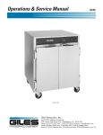
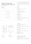
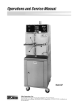
Operations & Service Manual
GHM4, GHM6,
& GHM8
Model: GHM4
Model: GHM6
Model: GHM8
Giles Enterprises, Inc.
2750 Gunter Park Drive West • Montgomery, AL 36109 USA
Fax: (334) 272-3561 • Internet: www.gilesent.com
Service Hotline (Toll Free): 1-800-554-4537 (USA & Canada Only)
Form No. 60329 (Release date: 9/00)(Revision Date: 10/01/03)(Rev B)
LIMITED WARRANTY
• Subject to the terms and conditions of this Limited Warranty as herein stated, all Giles
Enterprises, Inc., Foodservice Equipment and parts purchased new from an authorized Giles
Enterprises, Inc., representative are warranted as to defects in material or workmanship for a period
of 12 months from the date of installation, provided, however, that with regard to labor costs in
connection with this warranty, see below. All installations must be made by a qualified installing
agency in accordance with all applicable codes and/or regulations in the jurisdiction in which installed.
Limited warranty coverage is extended to the original owner only and is void if the unit is resold.
• During the Limited Warranty period, Giles Enterprises, Inc. will replace or recondition, at its
factory, any part or parts of this unit which Giles Enterprises, Inc. inspectors judge defective, provided
the unit has been subjected to normal usage, properly installed, operated and serviced. This Limited
Warranty does not cover cosmetic damage, and damage due to acts of God, accident, misuse,
alteration, negligence, abuse of the Giles Foodservice Equipment or the use of unorthodox repair
methods. All parts replaced under this Limited Warranty carry only the unexpired term of this Limited
Warranty. Limited Warranty service may be furnished only by an authorized Giles Enterprises, Inc.,
representative.
• If Limited Warranty service is requested, Giles Enterprises, Inc., will send factory-authorized
service representatives to repair, recondition, replace or inspect units of its manufacture with such
labor being rendered without cost to owner for ninety (90) days from the date of installation.
Otherwise, service, including labor and transportation charges or other expenses, in connection with
the removal or installation of any part or parts supplied under this Limited Warranty, are specified on
the original sales contract between the purchaser and the authorized Giles Enterprises, Inc.,
representative.
• Giles Enterprises, Inc. reserves the right to change or improve its equipment and parts in any
way, without obligation to alter such equipment or parts previously manufactured.
• Giles Enterprises, Inc. makes no further warranties, express or implied including implied warranties of merchantability or fitness for a particular purpose, and has no other obligation or liability not
specifically stated herein.
• Repair or replacement as provided under this limited warranty is the exclusive remedy. Giles
Enterprises, Inc., shall not be liable for any incidental or consequential damages for breach of any
express or implied warranty on this product, except to the extent prohibited by applicable law. Any
implied warranty of merchantability or fitness for a particular purpose on this product is limited in
duration to the duration of this limited warranty.
• Used Giles Enterprises, Inc., Foodservice Equipment or parts or Giles Enterprises, Inc.,
Foodservice Equipment or parts not purchased from an authorized Giles Enterprises, Inc.,
representative, carry no warranties, express or implied.
Table Of Contents
Safety
Model: GHM4, GHM6, & GHM8
........................................................v
Safety Overview . . . . . . . . . . . . . . . . . . . . . . . . . . . . . . . . . . . . . . . . . . . . . . . . . . . . . . . . . . . . . . . . . . . . v
Specific Safety Precautions . . . . . . . . . . . . . . . . . . . . . . . . . . . . . . . . . . . . . . . . . . . . . . . . . . . . . . . . . . . vi
1.
Introduction . . . . . . . . . . . . . . . . . . . . . . . . . . . . . . . . . . . . . . . . . . . . . . 1
1-1.
1-2.
1-3.
1-4.
1-4.1.
1-4.2.
1-4.3.
1-4.4.
1-4.5.
1-4.6.
Construction . . . . . . . . . . . . . . . . . . . . . . . . . . . . . . . . . . . . . . . . . . . . . . . . . . . . . . . . . . . . . . 1
Standard Features. . . . . . . . . . . . . . . . . . . . . . . . . . . . . . . . . . . . . . . . . . . . . . . . . . . . . . . . . . 1
Optional Features . . . . . . . . . . . . . . . . . . . . . . . . . . . . . . . . . . . . . . . . . . . . . . . . . . . . . . . . . . 1
Specifications . . . . . . . . . . . . . . . . . . . . . . . . . . . . . . . . . . . . . . . . . . . . . . . . . . . . . . . . . . . . . 2
Overall Dimensions for GHM4, GHM6, GHM8 . . . . . . . . . . . . . . . . . . . . . . . . . . . . . . . . . . . 2
Basic Steam Pan Configurations for GHM4, GHM6, GHM8 . . . . . . . . . . . . . . . . . . . . . . . . . 3
Profile of Base Options. . . . . . . . . . . . . . . . . . . . . . . . . . . . . . . . . . . . . . . . . . . . . . . . . . . . . . 4
Regulatory Listings . . . . . . . . . . . . . . . . . . . . . . . . . . . . . . . . . . . . . . . . . . . . . . . . . . . . . . . . . 5
Unit Weights . . . . . . . . . . . . . . . . . . . . . . . . . . . . . . . . . . . . . . . . . . . . . . . . . . . . . . . . . . . . . . 5
Number of Pan Wells, Heated Zones, and Lighted Zones . . . . . . . . . . . . . . . . . . . . . . . . . . . 5
2.
Installation . . . . . . . . . . . . . . . . . . . . . . . . . . . . . . . . . . . . . . . . . . . . . . . 7
2-01.
2-02.
2-03.
2-04.
2-05.
2-06.
2-07.
2-08.
2-08.1
2-09.
Location . . . . . . . . . . . . . . . . . . . . . . . . . . . . . . . . . . . . . . . . . . . . . . . . . . . . . . . . . . . . . . . . . 7
Unpacking . . . . . . . . . . . . . . . . . . . . . . . . . . . . . . . . . . . . . . . . . . . . . . . . . . . . . . . . . . . . . . . . 8
Counter Top Installation . . . . . . . . . . . . . . . . . . . . . . . . . . . . . . . . . . . . . . . . . . . . . . . . . . . . . 8
Base Installation . . . . . . . . . . . . . . . . . . . . . . . . . . . . . . . . . . . . . . . . . . . . . . . . . . . . . . . . . . 10
Installation of the Glass (Full Serve) and Heat Lamps . . . . . . . . . . . . . . . . . . . . . . . . . . . . . 12
Installation of the Glass (Self Serve) and Heat Lamps . . . . . . . . . . . . . . . . . . . . . . . . . . . . . 13
Electrical Requirements . . . . . . . . . . . . . . . . . . . . . . . . . . . . . . . . . . . . . . . . . . . . . . . . . . . . 14
Electrical Connections . . . . . . . . . . . . . . . . . . . . . . . . . . . . . . . . . . . . . . . . . . . . . . . . . . . . . 15
Electrical Connections Diagram . . . . . . . . . . . . . . . . . . . . . . . . . . . . . . . . . . . . . . . . . . . . . . 15
Ventilation of the Unit . . . . . . . . . . . . . . . . . . . . . . . . . . . . . . . . . . . . . . . . . . . . . . . . . . . . . . 16
3.
Overview . . . . . . . . . . . . . . . . . . . . . . . . . . . . . . . . . . . . . . . . . . . . . . . 17
3-01.
3-02.
3-03.
Back and Side View. . . . . . . . . . . . . . . . . . . . . . . . . . . . . . . . . . . . . . . . . . . . . . . . . . . . . . . . 18
Accessories (Included) . . . . . . . . . . . . . . . . . . . . . . . . . . . . . . . . . . . . . . . . . . . . . . . . . . . . . 20
Accessories (Not Included). . . . . . . . . . . . . . . . . . . . . . . . . . . . . . . . . . . . . . . . . . . . . . . . . . 22
4.
Unit Operation. . . . . . . . . . . . . . . . . . . . . . . . . . . . . . . . . . . . . . . . . . . 25
4-1.
4-2.
4-3.
4-4.
4-5.
4-6.
4-7.
Installation of Pans . . . . . . . . . . . . . . . . . . . . . . . . . . . . . . . . . . . . . . . . . . . . . . . . . . . . . . . . 26
Setting and Adjusting Temperature . . . . . . . . . . . . . . . . . . . . . . . . . . . . . . . . . . . . . . . . . . . . 28
Setting and Adjusting Heat Lamps . . . . . . . . . . . . . . . . . . . . . . . . . . . . . . . . . . . . . . . . . . . . 30
Cutting Board Installation . . . . . . . . . . . . . . . . . . . . . . . . . . . . . . . . . . . . . . . . . . . . . . . . . . . 31
Cutting Board Removal . . . . . . . . . . . . . . . . . . . . . . . . . . . . . . . . . . . . . . . . . . . . . . . . . . . . . 31
Normal Shut-Down . . . . . . . . . . . . . . . . . . . . . . . . . . . . . . . . . . . . . . . . . . . . . . . . . . . . . . . . 32
Emergency Shut-Down. . . . . . . . . . . . . . . . . . . . . . . . . . . . . . . . . . . . . . . . . . . . . . . . . . . . . 32
iii
Model: GHM4, GHM6, & GHM8
Table Of Contents
5.
Cleaning . . . . . . . . . . . . . . . . . . . . . . . . . . . . . . . . . . . . . . . . . . . . . . . . 33
6.
Troubleshooting . . . . . . . . . . . . . . . . . . . . . . . . . . . . . . . . . . . . . . . . . 35
7.
Parts List . . . . . . . . . . . . . . . . . . . . . . . . . . . . . . . . . . . . . . . . . . . . . . . 37
7–1.
7-2.
7-3.
7-4.
7-5.
Parts Ordering and Service Information . . . . . . . . . . . . . . . . . . . . . . . . . . . . . . . . . . . . . . . . 37
Control Panel Assembly . . . . . . . . . . . . . . . . . . . . . . . . . . . . . . . . . . . . . . . . . . . . . . . . . . . . 38
Element Assembly . . . . . . . . . . . . . . . . . . . . . . . . . . . . . . . . . . . . . . . . . . . . . . . . . . . . . . . . 40
Glass and Cutting Board Assembly . . . . . . . . . . . . . . . . . . . . . . . . . . . . . . . . . . . . . . . . . . . 42
Heat Lamp Assembly . . . . . . . . . . . . . . . . . . . . . . . . . . . . . . . . . . . . . . . . . . . . . . . . . . . . . . 44
8.
Wiring Diagram . . . . . . . . . . . . . . . . . . . . . . . . . . . . . . . . . . . . . . . . . . 47
8-01.
8-02.
8-03.
8-04.
8-05.
8-06.
8-07.
8-08.
8-09.
8-10.
8-11.
8-12.
Wiring
Wiring
Wiring
Wiring
Wiring
Wiring
Wiring
Wiring
Wiring
Wiring
Wiring
Wiring
iv
Diagram
Diagram
Diagram
Diagram
Diagram
Diagram
Diagram
Diagram
Diagram
Diagram
Diagram
Diagram
GHM4
GHM4
GHM4
GHM6
GHM6
GHM6
GHM6
GHM6
GHM6
GHM8
GHM8
GHM8
208-240/60/1 . . . . . . . . . . . . . . . . . . . . . . . . . . . . . . . . . . . . . . . . . . 48
220/50/1 . . . . . . . . . . . . . . . . . . . . . . . . . . . . . . . . . . . . . . . . . . . . . 50
380/50/3 . . . . . . . . . . . . . . . . . . . . . . . . . . . . . . . . . . . . . . . . . . . . . 52
FULL SERVE 208-240/60/1 . . . . . . . . . . . . . . . . . . . . . . . . . . . . . . . 54
SELF SERVE 208-240/60/1 . . . . . . . . . . . . . . . . . . . . . . . . . . . . . . . 56
FULL SERVE 220/50/1 . . . . . . . . . . . . . . . . . . . . . . . . . . . . . . . . . . 58
FULL SERVE 380/50/3 . . . . . . . . . . . . . . . . . . . . . . . . . . . . . . . . . . 60
SELF SERVE 220/50/1 . . . . . . . . . . . . . . . . . . . . . . . . . . . . . . . . . . 62
SELF SERVE 380/50/3 . . . . . . . . . . . . . . . . . . . . . . . . . . . . . . . . . . 64
FULL SERVE 208-240/60/1 . . . . . . . . . . . . . . . . . . . . . . . . . . . . . . . 66
SELF SERVE 208-240/60/1 . . . . . . . . . . . . . . . . . . . . . . . . . . . . . . . 68
FULL SERVE 380/50/3 . . . . . . . . . . . . . . . . . . . . . . . . . . . . . . . . . . 70
Safety
Model: GHM4, GHM6, & GHM8
Safety
Safety Overview
The instructions contained in this manual have been prepared to aid you in learning the proper procedures
for installing and servicing your new unit.
Throughout this manual, safety precautions are identified through the use of the safety alert symbol and
three signal words: DANGER, WARNING, and CAUTION. All safety alert information precedes the
step(s) to which they apply. Suggested, recommended, or other noteworthy information is identified
through the use of NOTES. Additionally, certain words are used to indicate a specific meaning or to add
emphasis.
The following words are used as indicated throughout the manual:
Shall: understood to be mandatory.
Should: understood to be advisory.
May: understood to be permissive.
Will: indicates a future event/condition to occur.
!
or
!
(Safety Alert Symbol)
Used in conjunction with signal words (DANGER, WARNING, or CAUTION) to alert you of potential personal injury hazards, immediately preceding precautionary measures that pertain to subsequent step(s).
Obey all safety messages that follow this symbol to avoid possible injury or death. Failure to adhere to
safety precautions identified by the safety alert symbol may also void the warranty.
! DANGER
• Indicates an imminently hazardous situation which, if not avoided, will result in death or serious injury.
! WARNING
• Indicates a potentially hazardous situation which, if not avoided, could result in death or serious injury.
! CAUTION
• Indicates a potentially hazardous situation which, if not avoided, may result in minor or moderate injury.
Also used to alert against unsafe practices.
CAUTION
• When used without the safety alert symbol, CAUTION indicates a potentially hazardous situation which,
if not avoided, may result in equipment/property damage, and void the warranty.
NOTE:
• Identifies suggested, recommended, or other noteworthy information.
v
Model: GHM4, GHM6, & GHM8
Safety
Specific Safety Precautions
For your safety, please observe the following precautions when operating or servicing your Giles equipment. Read the following important safety information to avoid personal injury and/or damage to the
equipment.
! DANGER
• Turn off the unit and unplug the power cord before cleaning or performing maintenance.
• DO NOT ADD WATER OR OTHER LIQUID SOLUTIONS! The food well area is not sealed and liquids will leak
onto the heating Elements underneath.
• DO NOT hose down the unit’s interior or exterior with water.
• Failure to comply with these DANGER notices will result in death or serious injury, equipment/property damage,
and void the warranty.
! WARNING
• Consult a qualified electrician to ensure that:
•• all electrical specifications and codes are met.
•• circuit breakers and wiring are of sufficient rating and gauge.
• The unit must be properly grounded and all electrical specifications must be met during installation.
• Improper installation, adjustment, alteration, service or maintenance could result in death or serious injury, equipment/property damage, and void the warranty.
• DO NOT use or store gasoline or other flammable liquids or vapors in the vicinity of this or any other appliance!
• Failure to comply with WARNING notices could result in death or serious injury and equipment/property damage
and void the warranty.
! CAUTION
• The unit must remain in the upright (vertical) position.
• Exercise care when removing the wooden crate from around the unit.
• DO NOT operate the unit unless you fully understand the components and their intended function (see Section
3).
• The unit and its parts are HOT!
Temperatures inside the unit may exceed 150°F (65.5°C).
Exercise caution when operating, loading/unloading food, cleaning or servicing.
Wearing of thermal oven mitts is recommended.
• Failure to comply with CAUTION notices may result in minor or moderate injury, equipment/property damage,
and void the warranty.
vi
Safety
Model: GHM4, GHM6, & GHM8
! CAUTION
• Food products must be maintained at a temperature of 150°F (65.5°C) minimum or in accordance with local or
state health regulations.
•
The unit must be adequately and properly grounded. Improper grounding may result in electrical shock.
Always refer to your local electrical code to ensure proper grounding of this or any other electrical equipment. Always consult with an electrician or other qualified service person to ensure breakers and wiring are
of sufficient rating and gauge for the equipment being operated.
• Units are available from the factory wired for various voltage, phase and hertz. Check the rating plate on the side of
the unit to determine the correct power supply.
• Ensure the unit is positioned in a secure, safe location
• Consult an electrician to ensure all electrical specifications have been met and the unit is properly grounded. The
wiring diagrams contained in this manual should aid your electrician in the installation of your unit.
• Allow the unit to cool down a minimum of 15 minutes before cleaning or servicing.
CAUTION
• The electronic components of the Control Panel are impact-sensitive. Exercise care around the Control Panel to
maintain proper operation.
• DO NOT install the unit next to combustible walls and materials. Failure to maintain safe distances may result in
fire.
• During cleaning of the unit
•• DO NOT steam clean.
•• DO NOT use products containing chlorine.
•• DO NOT use abrasive products, steel wool or scouring pads.
•• DO NOT use oven cleaner.
• Failure to comply with these CAUTION notices may result in equipment/property damage and void the warranty.
• DO NOT Modify, Alter or Add Attachments to This Equipment!
NOTE:
• If the crate is damaged upon receipt, immediately inspect the unit and notify the carrier of any damage to the
unit.
• To aid the electrician, an electrical wiring diagram is contained in this manual. Refer to the wiring diagram during
installation or servicing.
• Comply with all appropriate state and/or local heath regulations regarding the cleaning and sanitation of equipment.
vii
Model: GHM4, GHM6, & GHM8
Notes:
viii
Safety
Introduction
1.
Model: GHM4, GHM6, & GHM8
Introduction
Congratulations on the purchase of your new Giles Heated Merchandiser (GHM) manufactured by Giles
Enterprises, Inc., Montgomery, Alabama (USA), hereafter referred to as "Giles". Three different models
(GHM 4, GHM 6, and GHM 8) are available, each as a countertop model or with an optional base. Proper
care and maintenance of this unit will ensure years of trouble-free service.
The GHM has been developed with flexibility in mind, designed to maximize menu selections while keeping the food products fresh and maintaining them at the proper serving temperature, just waiting for your
customers to enjoy. Deli personnel have the option of displaying fresh prepared foods for full service, or
placing prepackaged foods for customer self-service. In either case, the products are highly visible and
appealing to the customer.
To help protect your investment in this equipment, we recommend taking a few moments to familiarize
yourself with the installation, cleaning and maintenance procedures contained in this manual. Read these
instructions before installation and use. Adherence to these recommended procedures minimizes the
potential for costly "down-time" and equipment repairs. Please retain this manual for future reference.
1-1. Construction
All of the unit’s exterior parts and the pan well are constructed of stainless steel. The unit is equipped
with a tempered European-style glass cover and utilizes safety coated heat lamps.
1-2. Standard Features
Temperature -Adjustable, variable control of well heaters, indicator lights verify unit operation.
Lighting -Adjustable, variable control of heat lamp output.
European-Style Glass -Allows maximum visibility of the product. Gas lift springs will hold the glass in
the open position for easy cleaning.
Fold Down Cutting Board -Folding and removable cutting board.
1-3. Optional Features
Self-serve -Available in a 24” section on the left or right side of the unit. Allows the customer to remove
product from the unit.
Glass color -Glass is available in clear, or mirror.
Base -Five bases are available: High Profile, Low Profile, Super Low Profile, Pedestal Profile, and
Standard.
1
Model: GHM4, GHM6, & GHM8
1-4. Specifications
1-4.1. Overall Dimensions for GHM4, GHM6, GHM8
INCHES [MILLIMETERS]
2
Introduction
Introduction
Model: GHM4, GHM6, & GHM8
1-4.2. Basic Steam Pan Configurations for GHM4, GHM6, GHM8
INCHES [MILLIMETERS]
3
Model: GHM4, GHM6, & GHM8
Introduction
1-4.3. Profile of Base Options
SLP-4, 6, or 8
PP-4, 6, or 8
LP-4, 6, or 8
FL-4, 6, or 8
HP-4, 6, or 8
INCHES [MILLIMETERS]
4
Introduction
Model: GHM4, GHM6, & GHM8
1-4.4. Regulatory Listings
UL (US and Canada)
UL Sanitation
CE
1-4.5. Unit Weights
Weights
Model
Uncrated w/o product or pans
Crated
lb
kg
lb
kg
GHM4
489
221.8
277
125.6
GHM6
621
281.7
390
177
GHM8
812
368.3
503
229
1-4.6. Number of Pan Wells, Heated Zones, and Lighted Zones
Heated Zones Lighting Zones Total Lights
Model
Pan Wells
GHM4
3
2
2
6
GHM6 Full Serve
5
3
3
10
GHM6 Self Serve
5
3
3
9
GHM8 Full Serve
7
4
4
14
GHM8 Self Serve
7
4
4
13
5
Model: GHM4, GHM6, & GHM8
Notes:
6
Introduction
Installation
Model: GHM4, GHM6, & GHM8
2. Installation
This section provides a summary of the procedures necessary for proper installation of your unit. To prevent
personal injury or equipment damage, please ensure the following steps are taken.
2-01. Location
CAUTION
• DO NOT MODIFY, ALTER OR ADD ATTACHMENTS TO THIS EQUIPMENT
1.
Keep the appliance and surrounding area free and clear from combustible materials. Always keep a
minimum clear distance of 6 inches [152.4 mm] in front of the unit.
2.
Please retain this manual for future reference.
3.
Please note wiring diagrams for this appliance are located in the rear of this manual. Ensure the
wiring diagram corresponds with the model being operated.
4.
Please ensure this appliance is electrically grounded in accordance with local codes, or in the absence
of local codes, with the National Electrical Code, ANSI/NFPA NO. 70-1999.
5.
Please provide adequate room for servicing and proper operation of this appliance. Also, provide
adequate ventilation in the operating area where necessary.
6.
Always consult with an electrician or other qualified service person prior to installation.
7.
Ensure voltage and amperage supplied to the unit are as specified on the unit’s rating plate.
8.
Make sure this unit is in a secure position and will not move.
The above steps will help to ensure safe and proper installation of your unit. If you have any questions concerning these procedures, contact your local Giles distributor or other qualified service person.
7
Model: GHM4, GHM6, & GHM8
Installation
2-02. Unpacking
Your unit may arrive enclosed by a wooden crate. The unit is secured to a wooden platform by means of hightensile strength strapping.
! CAUTION
• Exercise care when lifting or moving the unit.
• Exercise care when removing the wooden crate from around the unit.
• Failure to comply with these CAUTION notices may result in minor or moderate injury, equipment/property damage, and void the warranty.
NOTE:
• If the crate is damaged, immediately inspect the unit and notify the carrier of any damage to the
unit.
1.
Carefully cut and remove the plastic shipping wrap and the strapping mentioned above.
2.
Use pliers to loosen wire hooks which secure the wooden crate around the unit. Remove the
wooden crate.
3.
Carefully remove the unit from the shipping platform. Your new unit is extremely heavy, see Section
1.4.5 Unit Weights. Great care should be taken in lifting or moving the unit to prevent personal
injury or equipment damage.
2-03. Counter Top Installation
1.
There are (2) supplied Leg Mount Plates, attach (1) Leg Mount Plate to each leg.
Upper Leg
Leg Mount
Foot
2.
8
Fasten (4) supplied adjustable legs, (2) with Leg Mount Plates which should be diagonal from one
another, to the bottom of the unit.
Installation
Model: GHM4, GHM6, & GHM8
! CAUTION
• Exercise care when lifting or moving the unit.
• Ensure the counter and counter-top can support the weight of the unit. See 1-4.5 Unit Weights.
3.
Place the unit on the counter-top.
4.
Using the Adjustable legs, level the unit.
5.
Secure the unit to the counter-top by fastening the Leg Mounts to the counter-top with appropriate
screws (not supplied).
Rear Leg Mount
Front Leg Mount
(3) Screws (supplied by customer) each Leg Mount Plate
9
Model: GHM4, GHM6, & GHM8
Installation
2-04. Base Installation
1.
Prior to installing the GHM on the base 1 the unit must be leveled. Leveling of the base 1 can
be accomplished by adjusting the leveling feet 2 that are included with the base 1 . Confirm
the level of the base 1 by measuring both the length and width of the base with a 24” level.
1
2
2.
The Giles GHM units come with mounting screws to attach the unit to the base.These screws must
be used in the attachment of the case to the base. These screws are designed to meet sanitation
regulations by being the correct length to not allow any exposed threads.
3.
Non-specified screws,if used, must conform to applicable health and sanitation standards.
10
Installation
Model: GHM4, GHM6, & GHM8
4.
Once the unit has been installed on the base the seams between the base and the unit must be
caulked. This must be done internally and externally. A food grade caulk must be used to perform
the sealed joint.
5.
Depending on local and state health codes the base of the GHM must be sealed to the floor to
eliminate harborage of vermin. This is the responsibility of the installer to perform this task. It can
be completed by using a food grade sealant or stainless steel flashing attached to the base and then
sealed to the floor with food grade sealant.
6.
If flashing is to be used it must be attached with stainless steel self-tapping screws or bonding double sided adhesive. Other methods of fastening could potentially harm the painted surfaces causing
rust or other non-conformance issues with applicable health or sanitation codes.
7.
In locations where flashing is not permitted, the base can be mounted on 6” legs to comply with
local codes.
11
Model: GHM4, GHM6, & GHM8
Installation
2-05. Installation of the Glass (Full Serve) and Heat Lamps
1
2
1.
Install Rear Sliding Glass 1 .
2.
Install Side Glass 2 and 3 .
3.
Install Heat Lamps 4 .
12
4
3
Installation
Model: GHM4, GHM6, & GHM8
2-06. Installation of the Glass (Self Serve) and Heat Lamps
2
6
7
5
4
3
1.
Install Middle Glass Support 1 .
2.
Install Middle Glass 2 .
3.
Install Sneeze Guard Glass 3 .
4.
Install Side Glass 4 and 5 .
5.
Install Heat Lamps 6 .
6.
Install Rear Sliding Glass 7 .
1
13
Model: GHM4, GHM6, & GHM8
Installation
2-07. Electrical Requirements
! CAUTION
• The unit must be adequately and properly grounded. Improper grounding may result in electrical
shock. Always refer to your local electrical code to ensure proper grounding of this or any other
electrical equipment. Always consult with an electrician or other qualified service person to ensure
breakers and wiring are of sufficient rating and gauge for the equipment being operated.
Units are available from the factory in the voltages and phases listed below. Check the rating plate on the
side of the unit to determine the correct power supply.
Table 2-07. Electrical Breaker Requirements
14
Model
Voltage
Hz
Phase
Watts
GHM4
208
60
1
GHM4
240
60
GHM4
220
GHM4
AMPS
L1
L2
L3
Breaker
Required
2495
12
12
---
15
1
3120
13
13
---
20
50
1
2860
13
13
---
20
380
50
3
2990
4.5
4.5
4.5
10
GHM4
415
50
3
3120
5
5
5
10
GHM6
208
60
1
4556
17
17
---
30
GHM6
240
60
1
6065
20
20
---
30
GHM6
220
50
1
5560
20
20
---
30
GHM6
380
50
3
5810
7.5
7.5
7.5
10
GHM6
415
50
3
6065
8.5
8.5
8.5
10
GHM8
208
60
1
6380
31
31
---
35
GHM8
240
60
1
8490
35
35
---
50
GHM8
220
50
1
7770
35
35
---
50
GHM8
380
50
3
8140
10.5
10.5
10.5
15
GHM8
415
50
3
8630
12
12
12
15
Installation
Model: GHM4, GHM6, & GHM8
2-08. Electrical Connections
1.
Install appropriate Circuit Breakers in Main Breaker Box. See Table 2-07.
2.
Connect appropriate size Power Cable wire to the Main Breaker. Allow enough Cable so the unit
can be moved for cleaning and servicing.
3.
Remove the Service Box Cover. See Figure 2-06.1.
4.
Install the supplied Power Cable Strain Relief to the unit.
5.
Run the Power Cable through the Strain Relief and then tighten the Strain Relief.
6.
Connect appropriate Power Cable wires to the unit’s Terminal Blocks.
7.
Reinstall Service Box Cover.
8.
Turn Main Breaker on.
9.
Rotate each Temperature Knob and verify that the unit is heating.
10.
Rotate each Lighting Knob and verify the the lights turn on.
2-08.1
Electrical Connections Diagram
Power Cable
Strain Relief
Power cable
Service Box Cover
Terminal Blocks
Power Cable Wires from
Main Breaker
15
Model: GHM4, GHM6, & GHM8
Installation
2-09. Ventilation of the Unit
NOTE:
• Guidelines for proper ventilation system requirements may differ from location to location.
Always consult with local authorities to ensure compliance.
16
Overview
Model: GHM4, GHM6, & GHM8
3. Overview
The following section provides a brief overview of the components, functions, and accessories of the unit.
Please review this section carefully before proceeding any further.
Model: GHM4
Model: GHM6
Model: GHM8
17
Model: GHM4, GHM6, & GHM8
Overview
3-01. Back and Side View
7
8
6
1
18
2
3
4
5
Overview
Model: GHM4, GHM6, & GHM8
3-01. Back and Side View
Item
1
2
3
Description
Function
Fuse Holder
(GHM6 and GHM8 Only) Holds the 15 Amp fuse that completes
the electrical circuit to the heating lamps. There are two of these
on each unit.
Indicator Light
The Red Indicator light gives a visual indication of whether or not
the Elements are heating. The light is on (illuminated) while the
Elements are heating. The Indicator Light goes out once the
power has been removed from the Elements and they are no
longer heating. There is an Indicator Light for each Thermostat.
Thermostat
The SET TEMPERATURE knob is used to adjust the Thermostat
and achieve the desired temperature output of the heating
Elements. Other than OFF, settings range from 0 to 10,
incrementally (0 is the coolest setting and the 10 is the hottest).
The number of Thermostats vary with the GHM models.
4
Rheostat
The variable range LIGHTING knob is used to adjust the Rheostat
and achieve the desired brightness of the heat Lamps. The knob
is rotated clockwise for more lighting and counterclockwise for
less. The number of Rheostats vary by GHM model.
5
Service Entrance
The SERVICE ENTRANCE BOX cover provides access to the electrical connections from external power sources.
6
Lamps (Typical)
These Teflon coated 150 watt Lamps are located underneath the
hood of the display case, and provide lighting, as well as additional heat. The number of Lamps required varies with different GHM
models. Use of high wattage lamps could damage unit.
7
European Style
Glass
This attractive glass cover provides maximum visibility of the
products being displayed inside the case. It is attached with two
hinges containing gas lift springs that make it easy to raise for
cleaning.
8
Cutting Board
The cutting board may be folded up or down and is easily removable. It is used for a convenient place to prepare food.
19
Model: GHM4, GHM6, & GHM8
3-02.
Overview
Accessories (Included)
Part / Part Number
Description
Function
Pan Support
Channel (Long)
(2) -GHM4
(4) -GHM6
(6) -GHM8
Used to support Pans front to
back.
Giles P/N: 35788
Pan Support
Channel (Short)
(6) -GHM4
(15) -GHM6
(21) -GHM8
Used to support Pans left to right.
Giles P/N: 35789
(4) Leg
Used when installing the unit and
placing the unit on a
counter-top.
Giles P/N: 46766
(1) Power Cord
Strain Relief
Giles P/N: 20350
20
Used when installing the unit to
prevent strain on the power cord.
Overview
Model: GHM4, GHM6, & GHM8
3-02. Accessories (Included)
Part / Part Number
Description
Function
(2) Leg Mounting
Plate
Used when installing the unit to
secure the unit to a
counter-top
Heat Lamp
(6) -GHM4
(10) -GHM6
(14) -GHM8
Used to Light and Heat the
product
(2) Self Serve Tile
Used in the Self Serve Area
(Self Serve Model Only)
Middle Glass
Support Channel
Used to support the middle glass
used on the Self Serve Area
(Self Serve Model Only)
Giles P/N: 35533
Giles P/N: 25356 (130V) (60Hz units)
Giles P/N: 20088 (230V) (50Hz units)
Giles P/N: 66033
Giles P/N: 36006
21
Model: GHM4, GHM6, & GHM8
3-03.
Overview
Accessories (Not Included)
Part / Part Number
Description
Function
Steam Pan (Full size)
Used for Cooking and Displaying
food.
Steam Pan (1/2 size)
Used for Cooking and Displaying
food.
Giles P/N 76183 -2-1/2” DEEP
Giles P/N 76184 -4” DEEP
Giles P/N 76185 -2-1/2” DEEP
Giles P/N 76186 -4” DEEP
Steam Pan (1/3 size)
Giles P/N 76188 -2-1/2” DEEP
Giles P/N 76189 -4” DEEP
22
Used for Cooking and Displaying
food.
Overview
Model: GHM4, GHM6, & GHM8
3-03. Accessories (Not Included)
Part / Part Number
Description
Function
Steam Pan Grate (Full size)
Used to allow drainage on food.
Steam Pan Grate (1/2 size)
Used to allow drainage on food.
Steam Pan Grate (1/3 size)
Used to allow drainage on food.
Giles P/N: 76207
Giles P/N: 76208
Giles P/N: 70165
23
Model: GHM4, GHM6, & GHM8
Notes:
24
Overview
Operation
Model: GHM4, GHM6, & GHM8
4. Unit Operation
This section describes how to operate the unit.
Model: GHM4
Model: GHM6
Model: GHM8
25
Model: GHM4, GHM6, & GHM8
Operation
4-1. Installation of Pans
This section describes how to install the pan dividers and the warming pans.
! DANGER
DO NOT ADD WATER OR OTHER LIQUID SOLUTIONS! The food well area is not sealed and liquids will leak
onto the heating Elements underneath.
! CAUTION
Before installing pan dividers and the warming pans. Ensure the Heat Lamps and Set Temperature
knobs are in the OFF position see 4-6, Normal Shut-Down and the unit is cool.
1
2
3
4
1. Lift the Front Curved Glass 1 and/or Slide the Sliding Doors 2 open.
2. Install the Long Pan Support channels 3 at each Channel Placement angle 4 .
5
1
3. Install the Short Pan Support channels 5 between each of the Long Pan Support Channels 1 .
(Continued on next page.
26
Operation
4-1.
Model: GHM4, GHM6, & GHM8
Installation of Pans (Continued)
4. Install the Steam Pans in between the Long and Short Pan Support Channels. There are many pan configurations you may use; for some basic configurations see above.
NOTE:
Ensure there are NO gaps between Steam Pans. Any gaps will cause the unit to lose heat.
5. Close the Front Curved Glass and/or Slide the Sliding Doors closed.
27
Model: GHM4, GHM6, & GHM8
Operation
4-2. Setting and Adjusting Temperature
This section describes how to adjust the temperature of warming area.
2
1
2
1
1. Ensure the Front Curved Glass is lowered, and in the closed position.
2. Ensure the Sliding Glass Doors are in the closed position.
3. Preheat the GHM by rotating all the SET TEMPERATURE knobs 1 to the number 8 setting; the
Indicator Light 2 comes on. Allow the unit to preheat.
4. Once the Indicator Light(s) go out 2 , proceed to the next step.
! CAUTION
• The GHM and its parts are HOT! Temperatures inside the unit may exceed 150°F (65.6°C).
Exercise caution when operating, loading/unloading food, cleaning or servicing. Wearing of thermal oven mitts is recommended.
5. Wear appropriate hand protection and place hot food products into the Steam Pans of the GHM.
(Continued on next page)
28
Operation
4-2.
Model: GHM4, GHM6, & GHM8
Setting and Adjusting Temperature (Continued)
6. After placing the food products into the GHM, rotate the SET TEMPERATURE knob 1 to the number
6 setting.
! CAUTION
• Food products must have a minimum internal temperature of 150ºF (66ºC) before placing in the
GHM.
7.
Periodically monitor the temperature of the products inside the GHM and adjust the SET TEMPERATURE knob 1 as necessary.
NOTE:
• Proper temperature range for holding food product depends on the amount and type of product
contained in the GHM.
• Periodically check that food products are being maintained at the proper temperature.
• Temperature is manually adjusted using the SET TEMPERATURE knob settings, ranging from 10
(hottest) to 1 (coolest).
8. Follow local codes for hot holding temperatures.
29
Model: GHM4, GHM6, & GHM8
Operation
4-3. Setting and Adjusting Heat Lamps
This section describes how to illuminate interior of the unit.
2
2
1
1
! DANGER
• DO NOT touch the Heat Lamps. The Heat Lamps are very hot and skin contact with the Heat
Lamps may result in severe burns.
1. Rotate each Lighting knob 1 to adjust the Lighting intensity for each zone 2 .
NOTE:
• The unit uses 150 Watt Heat Lamps which not only illuminates the product, they also help heat
the product. Monitor the product closely to ensure the top of the product is not overcooking or
drying due to the Heat Lamps being set too high.
30
Operation
Model: GHM4, GHM6, & GHM8
4-4. Cutting Board Installation
This section illustrates how to install the cutting board to the unit.
4-5. Cutting Board Removal
This section illustrates how to remove the cutting board from the unit.
31
Model: GHM4, GHM6, & GHM8
Operation
4-6. Normal Shut-Down
This section explains the process of shutting the unit down.
3
1
1
2
3
2
1. Rotate all Heat Thermostats to the OFF 1 position, Indicator Lights 2 will go off.
2. Rotate all Lighting Rheostats to the OFF 3 position, all Display Lights will go off.
3. If required, turn off the unit’s circuit breaker in the main circuit breaker box to remove power to the
unit.
4-7.
Emergency Shut-Down
In case of emergency, remove power to the unit by turning off the facility circuit breaker.
32
Cleaning
Model: GHM4, GHM6, & GHM8
5. Cleaning
This section describes the cleaning of the unit. Not only is it important that your food products be appealing to the customer, but the cleanliness of the unit in which they are displayed is also vital. Your new
GHM is the show-case for your prepared food products and should be cleaned on a daily basis.
! DANGER
•
•
DO NOT hose down the unit’s interior or exterior with water.
Failure to comply with these DANGER notices will result in death or serious injury, equipment/property
damage, and void the warranty.
1. Perform a Normal Shut-Down procedure as described in section 4-6, then allow unit to cool.
2. Rotate the Front Curved Glass to the open position.
3. Wear appropriate hand protection (if necessary from residual heat) and remove all Serving Pans and
Pan Support Channels from the GHM. Place items in the sink for cleaning.
4. If needed, remove the Sliding Glass Door(s) by lifting upward until clear of lower track. Pivot the bottom of the door outward, then lower and remove. Place in an area suitable for cleaning.
5. Clean the interior and exterior of the GHM with soap and hot water. For difficult areas, use a mild
degradable nontoxic degreaser (such as Clear Magic or Simple Green).
6. Clean the glass parts of the GHM with an ordinary window cleaner.
7.
Polish all stainless areas outside the GHM with a good stainless polish.
8. Clean the Serving Pans and Pan Support Channels with soap and hot water.
9. Reinstall the Sliding Glass Door(s) by inserting top into the upper track. Pivot the bottom of the door
inward and align with lower track. Slide the door down into the lower track.
10. Rotate the Front Glass to the closed position.
11. Reinstall Pan Support Channels and the Serving Pans.
33
Model: GHM4, GHM6, & GHM8
Notes:
34
Cleaning
Troubleshooting
GHM4, GHM6, & GHM8
6. Troubleshooting
This section describes troubleshooting procedures for the unit. Refer to the wiring diagrams in Section 7
for more detailed analysis.
! DANGER
•
Electrical troubleshooting procedures should be done ONLY by qualified service personnel. Death or serious injury will result from contact with energized electrical components.
•
Failure to comply with these DANGER notices will result in death or serious injury, equipment/property
damage, and void the warranty.
Table 6-1. Troubleshooting Procedures
Problem
Probable Cause
Repair Procedure
Heat Lamps Not Working.
A. Blown fuse.
B. Incorrect wattage bulb.
A. Replace fuse.
B. Replace with correct wattage
bulb.
Unit not heating properly.
A. Unit not plugged in.
B. Unit not turned on.
C. Heating elements defective.
A. Plug unit in.
B. Turn unit on.
C. Call service technician to
replace defective heating
element.
Unit will not turn on.
A. Unit not plugged in.
B. Fuse is defective.
A. Plug unit in.
B. Unplug unit from power
source and replace fuse.
Unit will not maintain food
temperature of 150°F(65.6°C).
A. Unit not plugged in.
B. Unit not turned on.
C. Heating Elements defective.
A. Plug unit in.
B. Turn unit on.
C. Call service technician to place
defective Heating Element.
D. Insure food is at required
temperature before placing
into unit.
D. Food not at proper
temperature when place in
unit.
35
Model: GHM4, GHM6, & GHM8
Notes:
36
Troubleshooting
Parts List
7.
Model: GHM4, GHM6, & GHM8
Parts List
This section lists various parts that are available for replacement on the unit.
7–1. Parts Ordering and Service Information
If you require assistance or need repairs, please contact your area developer for a service agency in your
area. For further assistance, please contact the Giles Enterprises, Inc. factory at the following phone
numbers:
IN THE UNITED STATES, CANADA or MEXICO
Please call 1-800-288-1555 during normal business hours, 8:00AM-5:00PM Central Time Zone; other than
normal business hours, please call 1-800-288-1555, extension 314.
IN ALL OTHERS COUNTRIES
Please call 1-334-272-3528 during normal business hours, 8:00AM-5:00PM Central Time Zone; other than
normal business hours, please call 1-334-272-3528 extension 314.
INTERNET
Please visit our website on the world wide web at: www.gilesent.com.
The goal of the Giles team of professionals is to provide you with the highest quality of service and assistance. You can help us accomplish this by obtaining the following information and having it readily available when calling. The information is recorded on the Data Plate attached to the side of the unit.
The area below may be helpful in recording information for use as a quick reference.
Model Number: ______________________________________
Serial Number: ______________________________________
Phase:
___________________________________________
Voltage: ___________________________________________
Nature of Problem: __________________________________
37
Model: GHM4, GHM6, & GHM8
Parts List
7-2. Control Panel Assembly
1
2
3
4
7
5
8
6
38
9
Parts List
Model: GHM4, GHM6, & GHM8
7-2. Control Panel Assembly
Item No.
Part No.
Qty.
1
21950
2
GHM6
2
GHM8
2
GHM6
1
2
21900
2
3
Model Description
GHM4
3
3
GHM6
3
4
GHM8
2
GHM4
4
3
GHM6
4
4
GHM8
2
GHM4
5
3
GHM6
5
4
GHM8
2
GHM4
6
3
GHM6
6
4
GHM8
2
GHM4
7
3
GHM6
7
4
GHM8
2
GHM4
8
3
GHM6
8
4
GHM8
1
ALL
5
6
7
8
9
FUSE, 15AMP, SC-15
GHM8
2
4
HOLDER,FUSE,300V, 15A,SC 0 TO 15
22300
40777
20025
23701
40780
23702
36329
LIGHT, PILOT, 250V, ROUND, RED
KNOB, THERMOSTAT, NO DIAL PLATE
PLATE, KNOB DIAL 1-10, GHM
THERMOSTAT, 60-250 DEG, 208-240V, GHM
KNOB, RHEOSTAT VARIABLE GHM
RHEOSTAT, LAMP, 120V
PLATE, INSPECTION, (TERMINAL BLOCK COVER)
39
Model: GHM4, GHM6, & GHM8
Parts List
7-3. Element Assembly
2
3
4
1
40
Parts List
Model: GHM4, GHM6, & GHM8
7-3. Element Assembly
Item No.
Part No.
Qty.
1
20039
1
ALL
STRAP, 3/8" TUBE
2
38901
1
60Hz
TERMINAL BLOCK ASSY., 60Hz
2
37655
1
50Hz 1ø
TERMINAL BLOCK ASSY., 50Hz, 1ø
2
37762
1
50Hz 3ø
TERMINAL BLOCK ASSY., 50Hz, 3ø
3
25352
3
GHM4
3
5
GHM6
3
7
GHM8
3
GHM4
4
5
GHM6
4
7
GHM8
4
36009
Model Description
ELEMENT, ROUND, 208/240V
PLATE, HEAT DEFLECTION
41
Model: GHM4, GHM6, & GHM8
Parts List
7-4. Glass and Cutting Board Assembly
4
3
2
1
8
7
5 OR 9
5
6
42
Parts List
Model: GHM4, GHM6, & GHM8
7-4. Glass and Cutting Board Assembly
Item No.
Part No.
Qty.
1
40184
2
---
4
GHM8
1
Model Description
BRACKET, DROP SHELF, GHM
2
36142
1
GHM4
3 WELL, WORK SHELF, ASSY.
2
36131
1
GHM6
5 WELL WORK SHELF, ASSY
2
36123
1
GHM8
4 WELL WORK SHELF, ASSY
2
36122
1
GHM8
3 WELL WORK SHELF, ASSY
3
40287
1
GHM4
DOOR, LEFT, CLEAR
3
40369
1
GHM4
DOOR, LEFT, MIRROR
3
70432
1
GHM6
DOOR, LEFT, CLEAR
3
70449
1
GHM6
DOOR, LEFT, MIRROR
3
40207
1
GHM8
DOOR, LEFT, CLEAR
3
70446
1
GHM8
DOOR, LEFT, MIRROR
4
40286
1
GHM4
DOOR, RIGHT, CLEAR
4
40371
1
GHM4
DOOR, RIGHT, MIRROR
4
70149
1
GHM6
DOOR, RIGHT, CLEAR
4
70448
1
GHM6
DOOR, RIGHT, MIRROR
4
40208
1
GHM8
DOOR, RIGHT, CLEAR
4
70447
1
GHM8
DOOR, RIGHT, MIRROR
5
40182
2
ALL
SIDE, GLASS, CLEAR
5
40442
1
ALL
SIDE, GLASS, MIRROR, LEFT
6
40183
1
ALL S/S
MIDDLE, GLASS, CLEAR
7
40178
1
ALL S/S
GLASS, 2' SELF SERVE
8
40479
1
GHM4 S/S GLASS, 4' SELF SERVE
8
45156
1
GHM4 FUL GLASS, 4' FULL SERVE
8
45156
1
GHM6 S/S GLASS, 6' SELF SERVE
8
40179
1
GHM6 FUL GLASS, 6' FULL SERVE
8
40179
1
GHM8 S/S GLASS, 6' SELF SERVE
8
40514
1
GHM8 FUL GLASS, 51” FULL SERVE
8
45156
1
GHM8 FUL GLASS, 4’ FULL SERVE
9
40374
1
ALL
SIDE, GLASS, MIRROR, RIGHT
43
Model: GHM4, GHM6, & GHM8
Parts List
7-5. Heat Lamp Assembly
2
1
44
Parts List
Model: GHM4, GHM6, & GHM8
7-5. Heat Lamp Assembly
Item No.
Part No.
Qty.
Model Description
1
25356
6
GHM4
LAMP, 150W, 130V, TEFLON COATED, (60Hz Modes)
1
20088
6
GHM4
LAMP, 150W, 230V, TEFLON COATED, (50Hz Modes)
1
25356
8
GHM6
LAMP, 150W, 130V, TEFLON COATED, (60Hz Modes)
1
20088
8
GHM6
LAMP, 150W, 230V, TEFLON COATED, (50Hz Modes)
1
25356
10
GHM8
LAMP, 150W, 130V, TEFLON COATED, (60Hz Modes)
1
20088
10
GHM8
LAMP, 150W, 230V, TEFLON COATED, (50Hz Modes)
2
25355
6
GHM4
BASE, GHM LAMP, CERAMIC
2
8
GHM6
2
10
GHM8
45
Model: GHM4, GHM6, & GHM8
Notes:
46
Parts List
Wiring Diagram
Model: GHM4, GHM6, & GHM8
8. Wiring Diagram
The following section contains Wiring Diagrams for the various units. Please check the Serial Plate on the
side of the unit, as shown below, for the units Model Name, Voltage, Hertz, and Phase.
Serial Plate
47
Model: GHM4, GHM6, & GHM8
Wiring Diagram
8-01. Wiring Diagram GHM4 208-240/60/1
WIRING DIAGRAM P/N:
36376-D
48
Wiring Diagram
Model: GHM4, GHM6, & GHM8
8-01. Parts List for Wiring Diagram GHM4 208-240/60/1
Item
01
02
03
04
05
06
07
08
09
10
11
12
Part No.
20319
23701
23702
22300
25352
25355
25356
25275
20320
20321
20322
25300
Qty.
3
2
2
2
3
6
6
4
3
2
1
3
Description
TERMINAL BLOCK,50 AMP,AWG 8-24
THERMOSTAT, 60-250 DEG, 208-240V, GHM
RHEOSTAT, LAMP, 120V, GHM8
LIGHT, PILOT, 250V, ROUND, RED
ELEMENT, ROUND, 719/957W, 208/240V, GHM
BASE,GHM,LAMP,CERAMIC
LAMP, 150W, 130V, TEFLON COATED, GHM
WIRENUT, IDEAL BLUE
TERMINAL BLOCK,GROUNDING,AWG 8-24
TERMINAL MARKING STRIP,UK6N
BRIDGE,10 POSITION W/SCREWS
WIRENUT, 73B IDEAL ORANGE
49
Model: GHM4, GHM6, & GHM8
Wiring Diagram
8-02. Wiring Diagram GHM4 220/50/1
WIRING DIAGRAM P/N:
37109-C
50
Wiring Diagram
Model: GHM4, GHM6, & GHM8
8-02. Parts List for Wiring Diagram GHM4 220/50/1
Item
01
02
03
04
05
06
07
08
09
10
11
Part No.
20181
23701
23702
22300
25352
25355
20088
25275
20182
20183
20184
Qty.
3
2
2
2
3
6
6
2
3
2
1
Description
BLOCK,TERMINAL,24-10GA,30 AMP
THERMOSTAT, 60-250 DEG, 208-240V, GHM
RHEOSTAT, LAMP, 120V, GHM8
LIGHT, PILOT, 250V, ROUND, RED
ELEMENT, ROUND, 719/957W, 208/240V, GHM
BASE,GHM,LAMP,CERAMIC
LAMP,150W/250V,TEFLON COATED
WIRENUT, IDEAL BLUE
BLOCK UNIVERSAL GROUND TERMINAL 20-10GA
MARKING STRIP,TERM.BLKS,PHOENIX,UK5N_
BRIDGE, UNIVERSAL TERMINAL BLOCK, UK5N
51
Model: GHM4, GHM6, & GHM8
Wiring Diagram
8-03. Wiring Diagram GHM4 380/50/3
WIRING DIAGRAM P/N:
37568-C
52
Wiring Diagram
Model: GHM4, GHM6, & GHM8
8-03. Parts List for Wiring Diagram GHM4 380/50/3
Item
01
02
03
04
05
06
07
08
09
10
11
12
Part No.
20181
23701
23702
22300
25352
25355
20088
25300
20182
20183
20184
21950
Qty.
6
2
2
2
3
6
6
2
2
2
1
1
Description
BLOCK,TERMINAL,24-10GA,30 AMP
THERMOSTAT, 60-250 DEG, 208-240V, GHM
RHEOSTAT, LAMP, 120V, GHM8
LIGHT, PILOT, 250V, ROUND, RED
ELEMENT, ROUND, 719/957W, 208/240V, GHM
BASE,GHM,LAMP,CERAMIC
LAMP,150W/250V,TEFLON COATED
WIRENUT, 73B IDEAL ORANGE
BLOCK UNIVERSAL GROUND TERMINAL 20-10GA
MARKING STRIP,TERM.BLKS,PHOENIX,UK5N_
BRIDGE, UNIVERSAL TERMINAL BLOCK, UK5N
HOLDER, FUSE, 300V, 15A, SC 0 TO 15
53
Model: GHM4, GHM6, & GHM8
Wiring Diagram
8-04. Wiring Diagram GHM6 FULL SERVE 208-240/60/1
WIRING DIAGRAM P/N:
36375-C
54
Wiring Diagram
Model: GHM4, GHM6, & GHM8
8-04. Parts List for Wiring Diagram GHM6 FULL SERVE 208-240/60/1
Item
01
02
03
04
05
06
07
08
09
10
11
12
13
Part No.
20319
23701
23702
22300
25352
25355
25356
25275
21950
20320
20321
20322
25300
Qty.
6
3
3
3
5
10
10
8
2
2
2
1
4
Description
TERMINAL BLOCK,50 AMP,AWG 8-24
THERMOSTAT, 60-250 DEG, 208-240V, GHM
RHEOSTAT, LAMP, 120V, GHM8
LIGHT, PILOT, 250V, ROUND, RED
ELEMENT, ROUND, 719/957W, 208/240V, GHM
BASE,GHM,LAMP,CERAMIC
LAMP, 150W, 130V, TEFLON COATED, GHM
WIRENUT, IDEAL BLUE
HOLDER, FUSE, 300V, 15A, SC 0 TO 15
TERMINAL BLOCK,GROUNDING,AWG 8-24
TERMINAL MARKING STRIP,UK6N
BRIDGE,10 POSITION W/SCREWS
WIRENUT, 73B IDEAL ORANGE
55
Model: GHM4, GHM6, & GHM8
Wiring Diagram
8-05. Wiring Diagram GHM6 SELF SERVE 208-240/60/1
WIRING DIAGRAM P/N:
39073-B
56
Wiring Diagram
Model: GHM4, GHM6, & GHM8
8-05. Parts List for Wiring Diagram GHM6 SELF SERVE 208-240/60/1
Item
01
02
03
04
05
06
07
08
09
10
11
12
13
Part No.
20319
23701
23702
22300
25352
25355
25356
25275
21950
20320
20321
20322
25300
Qty.
6
3
3
3
5
9
9
8
2
2
2
1
4
Description
TERMINAL BLOCK,50 AMP,AWG 8-24
THERMOSTAT, 60-250 DEG, 208-240V, GHM
RHEOSTAT, LAMP, 120V, GHM8
LIGHT, PILOT, 250V, ROUND, RED
ELEMENT, ROUND, 719/957W, 208/240V, GHM
BASE,GHM,LAMP,CERAMIC
LAMP, 150W, 130V, TEFLON COATED, GHM
WIRENUT, IDEAL BLUE
HOLDER, FUSE, 300V, 15A, SC 0 TO 15
TERMINAL BLOCK,GROUNDING,AWG 8-24
TERMINAL MARKING STRIP,UK6N
BRIDGE,10 POSITION W/SCREWS
WIRENUT, 73B IDEAL ORANGE
57
Model: GHM4, GHM6, & GHM8
Wiring Diagram
8-06. Wiring Diagram GHM6 FULL SERVE 220/50/1
WIRING DIAGRAM P/N:
37110-C
58
Wiring Diagram
Model: GHM4, GHM6, & GHM8
8-06. Parts List for Wiring Diagram GHM6 FULL SERVE 220/50/1
Item
01
02
03
04
05
06
07
08
09
10
11
12
Part No.
20181
23701
23702
22300
25352
25355
20088
25300
21950
20182
20183
20184
Qty.
3
3
3
3
5
10
10
3
2
3
2
1
Description
BLOCK,TERMINAL,24-10GA,30 AMP
THERMOSTAT, 60-250 DEG, 208-240V, GHM
RHEOSTAT, LAMP, 120V, GHM8
LIGHT, PILOT, 250V, ROUND, RED
ELEMENT, ROUND, 719/957W, 208/240V, GHM
BASE,GHM,LAMP,CERAMIC
LAMP,150W/250V,TEFLON COATED
WIRENUT, 73B IDEAL ORANGE
HOLDER, FUSE, 300V, 15A, SC 0 TO 15
BLOCK UNIVERSAL GROUND TERMINAL 20-10GA
MARKING STRIP,TERM.BLKS,PHOENIX,UK5N_
BRIDGE, UNIVERSAL TERMINAL BLOCK, UK5N
59
Model: GHM4, GHM6, & GHM8
Wiring Diagram
8-07. Wiring Diagram GHM6 FULL SERVE 380/50/3
WIRING DIAGRAM P/N:
37569-C
60
Wiring Diagram
8-07.
Item
01
02
03
04
05
06
07
08
09
10
11
12
Model: GHM4, GHM6, & GHM8
Parts List for Wiring Diagram GHM6 FULL SERVE 380/50/3
Part No.
20181
20182
23701
23702
22300
25352
25355
20088
25300
21950
20183
20184
Qty.
6
2
4
4
4
5
10
10
4
2
2
1
Description
BLOCK,TERMINAL,24-10GA,30 AMP
BLOCK UNIVERSAL GROUND TERMINAL 20-10GA
THERMOSTAT, 60-250 DEG, 208-240V, GHM
RHEOSTAT, LAMP, 120V, GHM8
LIGHT, PILOT, 250V, ROUND, RED
ELEMENT, ROUND, 719/957W, 208/240V, GHM
BASE,GHM,LAMP,CERAMIC
LAMP,150W/250V,TEFLON COATED
WIRENUT, 73B IDEAL ORANGE
HOLDER, FUSE, 300V, 15A, SC 0 TO 15
MARKING STRIP,TERM.BLKS,PHOENIX,UK5N_
BRIDGE, UNIVERSAL TERMINAL BLOCK, UK5N
61
Model: GHM4, GHM6, & GHM8
Wiring Diagram
8-08. Wiring Diagram GHM6 SELF SERVE 220/50/1
WIRING DIAGRAM P/N:
39236-A
62
Wiring Diagram
Model: GHM4, GHM6, & GHM8
8-08. Parts List for Wiring Diagram GHM6 SELF SERVE 220/50/1
Item
01
02
03
04
05
06
07
08
09
10
11
12
Part No.
20181
23701
23702
22300
25352
25355
20088
25300
21950
20182
20183
20184
Qty.
3
3
3
3
5
9
9
3
2
3
2
1
Description
BLOCK,TERMINAL,24-10GA,30 AMP
THERMOSTAT, 60-250 DEG, 208-240V, GHM
RHEOSTAT, LAMP, 120V, GHM8
LIGHT, PILOT, 250V, ROUND, RED
ELEMENT, ROUND, 719/957W, 208/240V, GHM
BASE,GHM,LAMP,CERAMIC
LAMP,150W/250V,TEFLON COATED
WIRENUT, 73B IDEAL ORANGE
HOLDER, FUSE, 300V, 15A, SC 0 TO 15
BLOCK UNIVERSAL GROUND TERMINAL 20-10GA
MARKING STRIP,TERM.BLKS,PHOENIX,UK5N_
BRIDGE, UNIVERSAL TERMINAL BLOCK, UK5N
63
Model: GHM4, GHM6, & GHM8
Wiring Diagram
8-09. Wiring Diagram GHM6 SELF SERVE 380/50/3
WIRING DIAGRAM P/N:
39235-A
64
Wiring Diagram
Model: GHM4, GHM6, & GHM8
8-09. Parts List for Wiring Diagram GHM6 SELF SERVE 380/50/3
Item
01
02
03
04
05
06
07
08
09
10
11
12
Part No.
20181
20182
23701
23702
22300
25352
25355
20088
25300
21950
20183
20184
Qty.
6
2
4
4
4
5
9
9
4
2
2
1
Description
BLOCK,TERMINAL,24-10GA,30 AMP
BLOCK UNIVERSAL GROUND TERMINAL 20-10GA
THERMOSTAT, 60-250 DEG, 208-240V, GHM
RHEOSTAT, LAMP, 120V, GHM8
LIGHT, PILOT, 250V, ROUND, RED
ELEMENT, ROUND, 719/957W, 208/240V, GHM
BASE,GHM,LAMP,CERAMIC
LAMP,150W/250V,TEFLON COATED
WIRENUT, 73B IDEAL ORANGE
HOLDER, FUSE, 300V, 15A, SC 0 TO 15
MARKING STRIP,TERM.BLKS,PHOENIX,UK5N_
BRIDGE, UNIVERSAL TERMINAL BLOCK, UK5N
65
Model: GHM4, GHM6, & GHM8
Wiring Diagram
8-10. Wiring Diagram GHM8 FULL SERVE 208-240/60/1
WIRING DIAGRAM P/N:
35695-E
66
Wiring Diagram
Model: GHM4, GHM6, & GHM8
8-10. Parts List for Wiring Diagram GHM8 FULL SERVE 208-240/60/1
Item
01
02
03
04
05
06
07
08
09
10
11
12
13
Part No.
20319
23701
23702
22300
25352
25355
25356
25275
21950
20320
20321
20322
25300
Qty.
6
3
3
3
5
10
10
9
2
2
2
1
6
Description
TERMINAL BLOCK,50 AMP,AWG 8-24
THERMOSTAT, 60-250 DEG, 208-240V, GHM
RHEOSTAT, LAMP, 120V, GHM8
LIGHT, PILOT, 250V, ROUND, RED
ELEMENT, ROUND, 719/957W, 208/240V, GHM
BASE,GHM,LAMP,CERAMIC
LAMP, 150W, 130V, TEFLON COATED, GHM
WIRENUT, IDEAL BLUE
HOLDER, FUSE, 300V, 15A, SC 0 TO 15
TERMINAL BLOCK,GROUNDING,AWG 8-24
TERMINAL MARKING STRIP,UK6N
BRIDGE,10 POSITION W/SCREWS
WIRENUT, 73B IDEAL ORANGE
67
Model: GHM4, GHM6, & GHM8
Wiring Diagram
8-11. Wiring Diagram GHM8 SELF SERVE 208-240/60/1
WIRING DIAGRAM P/N:
39072-B
68
Wiring Diagram
8-11.
Item
01
02
03
04
05
06
07
08
09
10
11
12
13
Model: GHM4, GHM6, & GHM8
Parts List for Wiring Diagram GHM8 SELF SERVE 208-240/60/1
Part No.
20319
23701
23702
22300
25352
25355
25356
25275
21950
20320
20321
20322
25300
Qty.
6
3
3
3
5
10
10
9
2
2
2
1
6
Description
TERMINAL BLOCK,50 AMP,AWG 8-24
THERMOSTAT, 60-250 DEG, 208-240V, GHM
RHEOSTAT, LAMP, 120V, GHM8
LIGHT, PILOT, 250V, ROUND, RED
ELEMENT, ROUND, 719/957W, 208/240V, GHM
BASE,GHM,LAMP,CERAMIC
LAMP, 150W, 130V, TEFLON COATED, GHM
WIRENUT, IDEAL BLUE
HOLDER, FUSE, 300V, 15A, SC 0 TO 15
TERMINAL BLOCK,GROUNDING,AWG 8-24
TERMINAL MARKING STRIP,UK6N
BRIDGE,10 POSITION W/SCREWS
WIRENUT, 73B IDEAL ORANGE
69
Model: GHM4, GHM6, & GHM8
Wiring Diagram
8-12. Wiring Diagram GHM8 FULL SERVE 380/50/3
WIRING DIAGRAM P/N:
37111-C
70
Wiring Diagram
Model: GHM4, GHM6, & GHM8
8-12. Parts List for Wiring Diagram GHM8 FULL SERVE 380/50/3
Item
01
02
03
04
05
06
07
08
09
10
11
12
Part No.
20181
20182
23701
23702
22300
25352
25355
20088
25300
21950
20183
20184
Qty.
10
2
4
4
4
7
14
14
4
2
2
1
Description
BLOCK,TERMINAL,24-10GA,30 AMP
BLOCK UNIVERSAL GROUND TERMINAL 20-10GA
THERMOSTAT, 60-250 DEG, 208-240V, GHM
RHEOSTAT, LAMP, 120V, GHM8
LIGHT, PILOT, 250V, ROUND, RED
ELEMENT, ROUND, 719/957W, 208/240V, GHM
BASE,GHM,LAMP,CERAMIC
LAMP,150W/250V,TEFLON COATED
WIRENUT, 73B IDEAL ORANGE
HOLDER, FUSE, 300V, 15A, SC 0 TO 15
MARKING STRIP,TERM.BLKS,PHOENIX,UK5N_
BRIDGE, UNIVERSAL TERMINAL BLOCK, UK5N
71
Model: GHM4, GHM6, & GHM8
Notes:
72
Wiring Diagram
Giles Enterprises, Inc.
P.O. Box 210247 • 2750 Gunter Park Drive West • Montgomery, Al 36121-0247 USA
(334) 272-1457 • Service Hotline 1-800-554-4537 (USA & Canada Only) • FAX (334) 272-3561 • www.gilesent.com
Form No. 60329 (Release date: 09/00)(Revision Date: 10/01/03)(Rev B)(CSY)