1
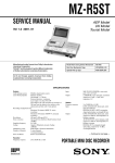
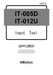
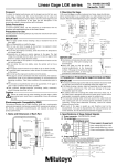
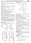
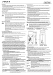
User’s Manual No.99MBC073B2 SERIES No.542 LGM System Motor Drive Unit Foreword NOTE In order to obtain the best possible performance and the longest service life from your LGM System Motor Drive Unit, read this user's manual thoroughly. After reading this manual store it in a safe place. The specifications of this motor drive unit and the descriptions of this manual are subject to change without prior notification. Safety Precautions To use this motor drive unit, observe the specifications, functions, and precautions for use. If the unit is used in other way, there is a risk of impairment of safety. Export Control Compliance 2. The combination setup of (5) Rotary Digital switch and (6) Measuring Speed Select switch allows you to set the operating speed with respect to the variation of the gage orientation. System Configuration This system consists of the linear gage unit that functions as a length sensor and this motor drive unit. The linear gage unit incorporates a motor to control the spindle (contact point) remotely from the motor drive unit. The following diagram shows the system configuration and the major function blocks. System Block Diagram The goods, technologies or software described herein may be subject to National or International, or Japanese Export Controls. To export directly or indirectly such matter without due approval from the appropriate authorities may therefore be a breach of export control regulations and the law. LGM Linear Gage Unit Motor Drive Unit Switch block Motor Electromagnetic Compatibility (EMC) This product complies with the EMC Directive. Note that in environments where electromagnetic interference exceeds EMC requirements defined in this directive, appropriate countermeasures are required to assure the product performance. Upper limit end sensor Power supply control block Service power supply for counter Position detector (Photoelectric reflection-type linear encoder) Precautions for Use WARNING Drive cable DC jack cable Neither removes the cover nor disassembles this unit. Otherwise you may be subject to electric shock or the unit may have a risk of causing breakage or fire as the result of short-circuiting due to metallic powders entered in the inside of the unit. Line driver Output cable 02ADH320A (L=1m) (standard specification) (standard specification) Be sure to use the supplied AC power cord and perform CAUTION grounding. DC_OUT (DC jack) is a service power supply (12VDC) dedicated to a single-axis counter (EH-101P counter, etc.). Do not connect it with anything other than the counter. Do not apply an abrupt shock due to a drop, etc., or excessive external force to the motor drive unit. Also, after completing measurement move the piston to the upper limit end to protect the piston from damage. Do not apply excessive tension to the cable or do not bend it forcibly. Do not use the motor drive unit around the high-voltage or large-current equipment. Also, do not share the power supply with such equipment. This motor derive unit should be used under the installation environment below: • Ambient temperature of 0 to 40°C with small temperature change and humidity of 80% or less with no condensation. • Place where can avoid direct sunlight and having less vibration. • Less dust, chip, and cutting oil (pollution degree 2 or better). • Altitude of 2000m or lower. • Over-voltage category II, power supply/voltage fluctuation within ±10%, and less noise. Warranty AC adapter 3. Setup 3.1 Connecting a Counter to the LGM System 1) Connect the plugs of the DC jack cable (02ADH320A) to the DC jack (11) and the DC jack on a counter, respectively, as shown in the figure above. The power is supplied from the motor drive unit to the counter. NOTE 2) Connect the plug on the ferrite core attached side to the DC jack on the motor drive unit. Connect the output cable from the linear gage to the Gage Input connector on the counter and lock the connector. For detailed information about the counter, refer to the linear gage counter user's manual. NOTE If the linear gage counter is used with its cables close to the power line of other equipment, a count error may result. Be sure to separate the cable lead from the power line. 3.2 Connecting the Linear Gage to the Motor Drive Unit Connect the drive cable from the linear gage unit to the GAGE connector (9) on the motor drive unit, and then lock the connector. 3.3 Connecting the Power Cable In the event that this motor drive unit should prove defective in workmanship or material, within one year from the date of original purchase for use, it will be repaired or replaced, at our option, free of charge upon its prepaid return to Mitutoyo. 1. 100 to 240VAC Ferrite core position Plug the supplied power cord in the AC inlet (8) firmly. Turn on the power switch (7), then check that the power ON/OFF LED lights up. NOTE Part Names and External Dimensions (13) (8) (14) (7) When turning on the power to the system first turn on the power to the motor drive unit, then turn on the power switch of the counter. (To shut off the system power, reverse this procedure.) (9) 4. Connector Specification 4.1 Drive Cable Signal (GAGE) connector (10) (11) The drive cable signals on the GAGE connector (9) are used to interface with the linear gage. For detailed information about the signals, refer to the user's manual of the linear gage. View from A 1) Connector type: HR1 OA-7R-6S (Hirose) 2) Pin assignment (viewed from the panel) (12) View from B (5) (6) (4) (3) (1) (2) (Unit mm) (1) Measurement switch, (2) DOWN switch, (3) UP switch, (4) Upper Limit Return switch, (5) Rotary Digital switch: Measuring speed setup switch (10 steps), (6) Measuring Speed Select switch: High/Low switchover, (7) Power switch, (8) AC Inlet, (9) Drive Cable Signal (GAGE) connector, (10) External I/O (EXT.) connector, (11) Service Power Supply for counter, (12) Power ON/OFF LED, (13) Serial label, (14) Electric shock warning label (Contact may cause electric shock or burn. Do not remove cover.) Pin No. Signal name 1 HOT 2 RET 3 4 N.C. +5V 5 6 LMT GND 4.2 External I/O (EXT.) connector It is possible to control the switch operation externally using the external input/output signals on the EXT connector (10). Also, it is possible to check that the spindle is located at the upper limit end by detecting the signal. 1) Connector type: HR10A-10R-10S (Hirose) 2) Pin assignment (viewed from the panel) Pin No. 1 2 3 4 5 6 7 8 9 10 6) Using the Output Signal Signal name GND PMON nEXUP nEXMEG nLIMIT nEXSTOP N.C. GND N.C. N.C. The motor drive unit outputs the LIMIT signal when the spindle returns to the upper limit end. Since this signal is outputted from a transistor open-collector, pull up the external input with the resistor as shown below. 5V 2SC3739 (NEC) 10k 0.01F 74HC14 or equivalent GND *Take noise-preventive measures separately. 3) Signal meaning GND : PMON : EXUP : Circuit ground 5VDC monitor (not available as a power supply) Signal (effective once the signal is inputted/open-collector input) having the same function as that of the Upper Limit Return switch. EXMEG : Signal (effective once the signal is inputted/open-collector input) having the same function as that of the Measurement switch. LIMIT : Spindle upper limit end detection signal (the signal is being outputted when the spindle is located upper limit end/open-collector output) EXSTOP : Operation stop signal (effective only while the signal is being inputted/open-collector input) * The signals are all based on the negative-true logic (active at a low level). NOTE External output circuit (reference) Motor drive unit side If the external input signal is used along with the panel switch signal, this may cause a malfunction in the system. If the system is under an unstable state, turn off the power once to perform power-on reset. 4) Applicable connector: HR10A-10P-10P (Hirose) 5) Using the Input Signals (1) Controlling the linear gage with switches or relay Connect toggle switches, etc., between connector terminals of each EXUP, EXMEG, and EXSTOP signals and GND to input the control signals to the motor drive unit. The EXUP or EXMEG signal provides an alternate operation (effective once the signal is inputted). The EXSTOP signal provides a momentary operation (effective in controlling the unit only while the signal is being inputted). To prevent a malfunction due to chattering, retain the signal input time for approximately 100ms or more. Also, to avoid an undefined operation, do not input two or more signals other than the EXSTOP signal at a time. The EXSTOP signal provides a momentary operation (effective in controlling the unit only while the signal is being inputted). The EXUP or EXMEG signal provides an alternate operation (effective once the signal is inputted) Motor drive unit side 5V 3.3k External switch Each signal input 100 0.01F GND (2) Controlling the linear gage with the electronic circuitry Use a transistor open-collector output circuit or a driver for inputting each signal of EXUP, EXMEG, and EXSTOP. The system accepts input of the EXUP and EXMEG signal, if the signal effective time (the duration of L level) is 100ms or more. Among the signals other than the EXSTOP signal the precedent input signal has the priority of execution. To avoid a system malfunction, do not input multiple signals at the same time. Motor drive unit side 5V 3.3k Each signal input Maximum rating/Ta=25°C Input voltage : 40V (V ceo) ON current : 500mA (Ic) 5. Specification 5.1 Control switch function Name (I) Measurement switch Description Press this switch once to feed the spindle to a workpiece at the specified speed. (2) DOWN switch The spindle is fed down while the DOWN switch for positioning the spindle is pressed, and stops when the DOWN switch is released. (3) UP switch The spindle is returned while the UP switch for positioning the spindle is pressed, and stops when the UP switch is released. (4) Upper limit Return switch Press this switch once to return the spindle to the upper limit end at a high speed. *1 (7) Power switch Power ON/OFF switch *1: To prevent a deviation due to vibration when the spindle is returned to the upper limit end with switch (4) or external signal EXUP, the motor drive unit performs restoration control in reverse direction using the switch (6) setup. Therefore, if the unit will not be used for measurement with the power being turned on, return the spindle to this position. 5.2 Measuring speed and measuring force (Standard type/reference value) measuring measuring speed force Switch (5) setting 3, switch (6) setting L 20.0mm/s 3.0N Normal gage orientation Switch (5) setting 4, switch (6) setting L 25.0mm/s 4.5N (*2, *3) Switch (5) setting 5, switch (6) setting L 30.0mm/s 6.0N Switch (5) setting 7, switch (6) setting L 20.0mm/s 6.5N Horizontal gage Switch (5) setting 9, switch (6) setting L 25.0mm/s 8.5N orientation (*3) Switch (5) setting I , switch (6) setting H 30.0mm/s 11.0N Switch (5) setting 4, switch (6) setting H 20.0mm/s 9.5N Reverse gage Switch (5) setting 6, switch (6) setting H 25.0mm/s 11.0N orientation (*3) Switch (5) setting 9, switch (6) setting H 30.0mm/s 13.0N Switch (4): Move the spindle to the upper limit end at a high Spindle speed (60mmls approx.). operation Switch (2), (3): Adjust (raise/lower) the spindle position. *2: Switches (5) and (6) are factory-set to '3' and ' L', respectively, assuming that the gage is used in the normal orientation. Depending on the settings of switches (5) and (6), the measuring speed and measuring force increase in the order of the following combinations: (5) '0' (6) 'L' < (5) '1' (6) 'L' < - - < (5) 'S' (6) 'H' < (5) '9' (6) 'H'. Select a combination of settings that provide reliable operation according to the gage orientation. *3: The measuring speed and measuring force specified for each combination of settings may generate an error due to the instrumental error and operating environments. Take that a measuring speed has an error of ±20% (reference value) and a measuring force has an error of ±30% (reference value) into account. Switch setting of (5) and (6) 5.3 Others Item Power voltage range Power consumption DC output (jack (11)) External I/O signal (EXT. connector (10)) External output circuit (reference) Driver: TD62503 (Toshiba) 100 0.01F GND *Take noise-preventive measures separately. Input voltage : ON current : 5V (minimum) 40mA (minimum) *The basic operation of each signal is identical to that under switch control. Mass Operating temperature range (humidity range) Storage temperature range (humidity range) Accessories CE marking Specification 100V to 240VAC, frequency: 50/60Hz, 5 to 10W Service power supply dedicated to a single-axis counter (EH-101P counter, etc.) Input signal UP signal: Same function as that of the UP switch (4) Measurement signal: Same function as that of the Measurement switch (I) Stop signal: Stops/cancels the spindle operation. Output signal Upper limit end detection signal Input/output signal Open collector specification 680g approx. (excluding accessories) 0 to 40°C (20 to 80%RH, with no condensation) -10 to 40°C (20 to 80%RH, with no condensation) AC power cord DC jack cable: 02ADH320A (length: 1m) EMC Directive:EN61326-1 Immunity test requirements :Clause 6.2 Table2 Emission limit :Class B Low voltage Directive: EN61010-1 20-1, Sakado 1-Chome, Takatsu-ku, Kawasaki-shi, Kanagawa 213-8533, Japan