1
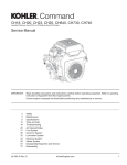
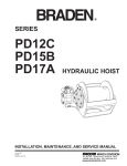
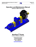
SERVICE
BULLETIN
2300 Oregon Street
Sherwood, Oregon
97140-9799 USA
DATE: January 8, 2007
PAGE: 1 of 10
•
Tel (503) 625-2560
•
Fax (503) 625-7616
BULLETIN NO.: ______________CSB0033
SECTION: _________ Operation & Service
MODEL(S): ______________________ All
Subject: Inspection, Testing, Preventive Maintenance and Special Operating Instructions For Braden /Gearmatic
Planetary Hoists
READ AND UNDERSTAND THESE ENTIRE INSTRUCTIONS BEFORE OPERATING OR SERVICING
YOUR BRADEN/GEARMATIC HOIST. RETAIN THESE INSTRUCTIONS FOR FUTURE REFERENCE.
FAILURE TO PROPERLY OPERATE, MAINTAIN AND SERVICE A HOIST MAY LEAD TO LOSS OF
LOAD CONTROL AND RESULT IN PROPERTY DAMAGE, SERIOUS INJURY OR DEATH.
These instructions apply to the following planetary hoists:
PD5/GH5/BG6 (any design series)
PD7/BG8 (any design series, Equal Speed only)
PD12 (any design series)
PD15B (“B” design series only)
PD17A
CH150A, CH175A, CH185A, CH210A
CH230A, CH240A, CH330A, CH400A
CH500A, CH600A, CH640
CH22B (“B” design series only)
GH30, GH50 (with external motor & brake valve)
ANY TIME A HOIST EXHIBITS ERRATIC OPERATION AND/OR UNUSUAL NOISE, THE HOIST MUST
BE TAKEN OUT OF SERVICE UNTIL IT IS INSPECTED AND SERVICED BY A QUALIFIED TECHNICIAN. CONTINUED OPERATION OF A HOIST WITH A DEFECT IN A CRITICAL COMPONENT MAY
LEAD TO LOSS OF LOAD CONTROL, PROPERTY DAMAGE, SERIOUS INJURY OR DEATH.
Record Retention:
Usage and Inspection:
A log of written, dated and signed records of ALL inspections, load tests, maintenance, repairs or modifications
must be kept readily available in an appropriate location
for a minimum of four (4) years. To provide customers with qualified outlets for hoist service and repairs,
BRADEN has established authorized Service Centers.
These Service Centers have factory trained service
technicians, up-to-date service information, extensive
parts inventories, complete testing facilities and are
audited by BRADEN on a regular basis for compliance.
BRADEN strongly recommends the use of BRADEN authorized Service for maintenance, repair and inspection
of BRADEN/Gearmatic products. Contact the Braden
Technical Support Department at 918- 251-8511 for the
names of current authorized Service Centers.
Inspection procedures for hoists are divided into five
general categories based upon their usage or duty
cycle, which in turn determines different, appropriate
intervals for inspections. The usage categories must
be assigned by the crane user on a consistent craneby-crane basis. The five crane/hoist usage categories
are as follows:
Idled - The crane/hoist has not been used for three
months.
Infrequent Usage - The crane/hoist is used less than
ten hours per month based on a three month average.
Moderate Usage - Crane/hoist used 10 - 50 hours per
month based on a three month average.
Heavy Usage - Crane/hoist used 50 - 200 hours per
month.
Severe Duty - Crane/hoist is operated more than 200
hours per month OR where 50% of the lifts exceed
75% of the Braden rated capacity for the hoist.
Allied Systems Co. reserves the right to make changes to new equipment without incurring the obligation to make such changes to equipment previously manufactured.
Printed in USA
The following chart lists the inspections that are required for each type of usage category.
NOTE:
FOR IDLED UNITS WITH UNKNOWN MAINTENANCE AND REPAIR HISTORY, IT IS HIGHLY
RECOMMENDED THAT THE HOIST UNDERGO A TEAR DOWN INSPECTION PRIOR TO BEING PLACED
INTO SERVICE. IF PERSONNEL LIFTING IS EXPECTED WITH SUCH A HOIST, A TEAR DOWN INSPECTION IS REQUIRED BEFORE USE.
Pre-Use or Daily Inspection:
Must include but is not limited to the following inspections that will be performed prior to placing the crane into
service and then as necessary during extended operation. This inspection must be performed by a qualified
crane operator or qualified crane inspector.
1. Check for external oil leaks and repair as necessary.
CSB0033
PAGE: 2 of 10
This is extremely important due to the accelerated
wear that will result from insufficient lubricating oil
in the hoist. Hoists with a sight glass; check oil level
daily. Hoists without a sight glass; check oil level
monthly if no external oil leaks are detected. Lubricant level must be maintained between the minimum
and maximum levels; midway up sight glass or at
bottom of level plug port as equipped. Use only the
recommended type of lubricant. Refer to the specific hoist service manual and/or the latest revision
Braden Service Bulletin 503.
2. Check the ratchet and pawl mechanism (if
equipped) for proper operation and full, spring force
engagement of the pawl with the ratchet wheel.
Adjust or repair as necessary.
3. Check hydraulic fittings and hoses for chaffing, deterioration or corrosion and repair as necessary.
4. Visually inspect for corroded, loose or missing bolts,
pins or other fasteners and replace or tighten as
necessary.
5. Visually inspect rotation indicator transmitters, antitwo-blocking switches and other safety equipment
and repair as necessary.
Annual Inspection:
This inspection must be carried out by a qualified
crane inspector. The annual inspection MUST
include, but not be limited, to the following:
1. Perform the Pre-Use/Daily Inspection, Quarterly
inspection and Semi-Annual Inspection.
2. Change the lubricating oil in the hoist gear cavity
after an oil sample has been taken as described
on page 5. Refill the hoist to the proper level with
recommended lubricant. Refer to Braden Service
Bulletin 503 Rev. 3.
Quarterly Inspection (every three months):
Must include but is not limited to the following inspections that must be performed by a qualified crane
operator or qualified crane inspector. A qualified crane
inspector shall perform inspections on cranes assigned
a moderate, heavy or severe usage category.
1. Perform the pre-use inspection.
2. On hoists used for personnel handling, the internal
spring-applied brake shall be tested in accordance
with the procedure on page 6 of these instructions.
3. Inspect for corrosion of fasteners, hoist base, drum,
etc. and repair/replace as required to maintain the
structural integrity of the hoist.
Semi-Annual Inspection (every six months):
Must include but is not limited to the following inspections that must be performed by a qualified crane
operator or qualified crane inspector. A qualified crane
inspector shall perform inspections on cranes assigned
a moderate, heavy or severe usage category.
1. Perform the Pre-Use and Quarterly inspections.
2. Take a sample of the lubricant from the hoist gear
cavity as described on page 5 and analyze it for
wear metals content, correct viscosity, lubricant
deterioration, moisture and other contaminants. If
the oil sample contains an high amount of metallic
particles, the hoist must be taken out of service to
undergo a tear down inspection.
FAILURE TO USE THE PROPER TYPE AND
VISCOSITY OF PLANETARY GEAR OIL
MAY CONTRIBUTE TO INTERMITTENT
BRAKE CLUTCH SLIPPAGE WHICH COULD
RESULT IN PROPERTY DAMAGE, SEVERE
PERSONAL INJURY OR DEATH. SOME
GEAR LUBRICANTS CONTAIN LARGE
AMOUNTS OF EP (EXTREME PRESSURE)
AND ANTI-FRICTION ADDITIVES WHICH
MAY CONTRIBUTE TO BRAKE CLUTCH
SLIPPAGE OR DAMAGE TO BRAKE FRICTION DISCS OR SEALS. OIL VISCOSITY
WITH REGARD TO AMBIENT TEMPERTURE
IS ALSO CRITICAL TO RELIABLE BRAKE
CLUTCH OPERATION. OUR TESTS INDICATE THAT EXCESSIVELY HEAVY OR
THICK GEAR OIL MAY CONTRIBUTE TO
INTERMITTENT BRAKE CLUTCH SLIPPAGE. MAKE CERTAIN THAT THE GEAR
OIL VISCOSITY USED IN YOUR HOIST IS
CORRECT FOR YOUR PREVAILING AMBIENT TEMPERATURE.
NOTE: OIL ANALYSIS CANNOT DETECT NOR
WARN AGAINST A FATIGUE FAILURE.
CSB0033
PAGE: 3 of 10
Tear-down Inspection:
Tear down inspections of BRADEN hoists should be
completed per the usage schedule defined below.
Magnetic Particle Inspection (MPI) of the internal ring
gear and reduction gears must be performed during
tear down inspections to aid in the detection of cracks
in the ring gears due to fatigue. The preferred inspection method is the Fluorescent Wet Magnetic Particle
Inspection using ultraviolet light consistent with ASTM
E709. For further information related to this inspection, and for testing of the older CH150 ring gears, P/N
24446, refer to BRADEN Service Bulletin LIT2162.
Severe Duty - Perform tear down inspection/MPI annually.
Heavy Usage - Perform tear down inspection/MPI at
least every (3) years.
Moderate Usage - Perform tear down inspection/ MPI
at least every (4) years.
Infrequent Usage - Perform tear down inspection/MPI
at least every (5) years.
It is strongly recommended that any moderate or infrequent usage hoist that is also used for personnel lifting
undergo tear down inspections on a maximum basis of
once every (3) years.
Any hoist that has NOT been subject to regular oil
sample analysis must undergo a tear down inspection on an annual (12 month) basis. Also, if a hoist
has an unknown history of repair and/or maintenance,
it is highly recommended that the hoist undergo a tear
down inspection prior to being placed into service.
NOTE: OIL ANALYSIS ALONE CANNOT DETECT NOR WARN AGAINST COMPONENT
FATIGUE FAILURE.
CSB0033
PAGE: 4 of 10
A tear down inspection includes the hoist being completely disassembled, cleaned, inspected and repaired
as required. Replacement of all worn, cracked, corroded or distorted parts, such as pins, bearings, shafts,
gears, brake rotors, brake plates, drum and base
should occur as required. All seals and O-rings should
be replaced at this time. Any deficiencies, including
but not limited to those above, shall be corrected
immediately. All of the following operations MUST be
performed
BEFORE the hoist is placed back into service.
1. The rebuilt hoist MUST be line pull tested to the
rated load of the hoist (hoist rating will vary with
motor, gear ratio and drum options) with a dynamometer or equivalent load measuring device. This
test load shall be the maximum rating of the hoist
for the specific application (at the normal relief valve
setting for the hoist) - NOT the reduced rating used
for personnel lifts.
2. The hoist must be dynamically tested by rotating the
drum several times, in both the hoisting and lowering directions, while under a load of at least 30% of
the hoist lifting capacity. Check for smooth operation
during this procedure.
3. The hoist internal friction brake shall be tested per
the procedures on page 6 of this manual.
4. After inspection or rebuild and testing, a new certificate for personnel handling shall be issued by
the inspector / service technician, effective on the
date the hoist is placed back in service. A sample
certificate is shown below, and shall include, at a
minimum, all of the information depicted here.
Oil Change
The hoist gear oil must be changed after the first 100
operating hours then on an annual basis, at a minimum
thereafter. In severe duty applications, the gear oil
should be changed every six months. Use the recommended lubricants. Refer to the applicable hoist service
manual or Braden Service Bulletin 503 Rev. 3 or later
for the recommended lubricants.
General guidelines for iron contaminant level:
100-500 ppm
Normal
500-800 ppm
Caution - Abnormal Sample. Change
oil and retake sample after 50 hours of
operation. If second sample is above
500 ppm, remove hoist from service
and perform tear-down inspection to
determine source of contamination.
800+ ppm
Unacceptable. Remove hoist from service and perform tear-down inspection
to determine source of contamination.
Gear Oil Sampling and Analysis
Proper gear oil sampling and analysis is a vital part
of a comprehensive preventive maintenance program.
Information obtained from the oil analysis allows
the maintenance technician to substitute preventive
maintenance for more costly unscheduled down time
or a far more dangerous failure. Early detection of
accelerated component wear allows the scheduling of
corrective maintenance. Prepare the hoist by cleaning
the drain plug area and drain extension tube in order to
obtain an uncontaminated sample. Operate the hoist in
both directions for one or two minutes to thoroughly mix
the gear oil then take the sample from the “midstream”
flow of the oil to obtain an accurate representation of
the oil condition. After taking the oil sample continue
with the oil change or refill the hoist gear cavity to the
proper level with recommended lubricant.
Iron contaminant levels will be on the high side of
“Normal” during break-in.
Equally important as the level of contamination is the
change in level of contamination. An effective oil analysis
program should provide the technician with a view of the
progression of wear or a trend. If a sample shows a sudden rise in contaminant level action should be taken to
determine “what has changed”.
NOTE: OIL ANALYSIS CANNOT DETECT NOR
WARN AGAINST A FATIGUE FAILURE.
HOT OIL MAY CAUSE PERSONAL INJURY
AND/OR BURNS TO UNPROTECTED SKIN.
MAKE CERTAIN THE OIL HAS COOLED TO
A SAFE TEMPERATURE (TYPICALLY LESS
THAN 110°F OR 43°C) BEFORE TAKING AN
OIL SAMPLE, CHANGING OIL OR SERVICING THE HOIST
CSB0033
PAGE: 5 of 10
BRAKE TEST PROCEDURE FOR BRADEN/Gearmatic HOISTS
All BRADEN planetary hoists have a spring applied, hydraulically released, multiple disc brake
inside the hoist housing (Gearmatic hoists have a
large single brake disc). This brake holds a suspended load when the directional control valve
is in neutral, or when hydraulic power is lost. A
brake clutch assembly permits the power train and
drum to rotate in the direction to lift a load, while
the brake remains fully applied. A load cannot be
lowered, however, without applying hydraulic pressure to the release port and releasing the brake.
Hoists ordered for personnel handling cranes will
have a needle valve in the brake release line. They
will also have a tee in the brake release line between the
needle valve and the brake release port on the hoist. One
opening in the tee is capped. With the valve closed and
the cap removed from the tee, the brake is isolated from
system pressure and vented to atmosphere. The brake
cannot be released under these conditions by actuating
the directional control valve.
One purpose of the valve/tee combination is to provide a
means to test the brake; the other is to provide a means to
lower a load when hydraulic power is lost.
Brake Test Procedure (Hoists Equipped With
Brake Valves)
(Test to be performed with no load on the hoist.)
Remove the lockwire on the needle valve handle and
close the valve tightly.
Remove the plug or cap in the tee (in the brake release circuit).
With the hydraulic power unit running, move the
directional control valve handle slowly to the full open,
lowering position.
Increase the engine speed, if necessary, to bring system pressure up to the relief valve setting. The hoist
drum should remain stationary.
If the drum rotates, the hoist should be disassembled
CSB0033
PAGE: 6 of 10
and the brake components should be examined for wear.
In addition, the brake springs should be measured for
correct free length in those hoists using helical compression springs.
Replace any parts showing excessive wear and any
spring whose length is shorter than the minimum shown
in the applicable hoist Service Manual. Reassemble the
brake and hoist and repeat the above steps.
When testing is complete, be sure to reinstall the plug
or cap in the tee, fully open the needle valve and install
lockwire to secure the valve in position.
The above procedure utilizes the hoist hydraulic
motor to test the brake’s ability to resist approximately
115% of the rated hoist load.
measured for the correct free length in those hoists using
Brake Test Procedure (For Standard Hoists Not helical compression springs.
Equipped With The Needle Valve)
(Test to be performed with no load on the hoist)
Remove and cap or plug the brake release line from
fitting in the hoist brake release port.
With the hydraulic power unit running, move the
directional control valve handle slowly to the full
open, lowering position.
Increase the engine speed, if necessary, to bring
system pressure up to the relief valve setting. The
hoist drum should remain stationary.
If the hoist drum rotates, the hoist should be disassembled and the brake components should be examined for wear. In addition, the brake springs should be
Replace any parts showing excessive wear, and any
spring whose free length is shorter than the minimum
shown in the applicable hoist Service Manual.
Reassemble the brake and hoist and repeat the
above steps.
When testing is complete, reattach the brake
release line to the brake release port fitting.
The above procedure utilizes the hoist hydraulic
motor to test the brake’s ability to resist approximately
115% of the rated hoist load.
CSB0033
PAGE: 7 of 10
EMERGENCY LOWERING PROCEDURES FOR HOISTS WITH GEAR
MOTORS
The following procedure releases the multiple disc brake
while leaving the brake valve closed. Since
gear type motors are not zero leakage devices, internal motor leakage permits the load to slowly rotate the
motor although its outlet is blocked by the closed brake
valve. This procedure will NOT work if there is little or no
oil in the motor. Using properly rated pipe and fittings,
the standpipe described below may be permanently
installed in the hydraulic system to avoid installing one
in an emergency.
1. Remove the lockwire on the needle valve handle and
close the valve tightly.
THE STANDPIPE REFERRED TO IN STEP
(3) BELOW MUST BE USED. ATTEMPTING THIS PROCEDURE WITH NO OIL IN
THE MOTOR OR WITH THE BRAKE VALVE
STUCK IN THE OPEN POSITION WILL
CAUSE THE LOAD TO FREE FALL, WHICH
COULD RESULT IN PROPERTY DAMAGE,
PERSONAL INJURY OR DEATH.
2. Remove the plug in the tee.
3. Remove both main hoses from the motor. Attach a
standpipe to the lowering motor port (opposite side
of the motor from the brake valve). Install a plug into
the hoisting port in the brake valve. The standpipe
is simply a length of pipe (approximately 12 inches
(305 mm) long) attached to a 90° elbow. The other
end of the elbow is attached to the lowering motor
port or manifold. The standpipe is installed with the
long, open end pointing up in a vertical position to
serve as a small reservoir. While the load is being
lowered, hydraulic oil MUST be added to the standpipe as necessary to prevent the motor from running
dry.
4. Fill the standpipe with hydraulic oil, making certain
that oil is not running out of the brake valve. If oil is
running out of the brake valve, stop the emergency
lowering procedure. Remove the spring retainer
CSB0033
PAGE: 8 of 10
and tap the main spool of the brake valve to the
closed position. Replace the spring retainer. After
completing the emergency lowering procedure, the
brake valve MUST be serviced and repaired if the
spool was stuck.
5. Connect a hand pump to the open port in the tee.
6. Slowly operate the hand pump up to no more
than 1,000 psi (6,900 kPa). A suspended load will
slowly come down when the static brake is released. Releasing the pressure on the hand pump
will cause the load to stop. If a chattering noise is
heard while the load is coming down, pump the
hand pump to a slightly higher pressure until the
DO NOT TOUCH THE MOTOR, BRAKE
VALVE, OR STANDPIPE WHILE LOWERING A LOAD. THEY MAY BECOME HOT
ENOUGH TO CAUSE BURNS.
noise stops. Do not exceed 1,500 psi (10,350kPa)
to the brake release port.
7. Always remove the hoist from service to inspect
the brake components for signs of overheating and
replace if necessary following this procedure. Refer
to the applicable Braden or Gearmatic service
manual for details.
8. If this procedure was performed due to a ma function of the hoist, remove the hoist from service and
perform a complete teardown and inspection to
correct the cause of the malfunction before returning the hoist to service.
PERSONNEL HANDLING
BRADEN recognizes that most hoists and cranes
are designed and intended for handling materials
and not personnel. The crane or hoist is only to
be used to handle personnel if it can be shown
there is no less hazardous way of carrying out
the job. In these situations, all safety precautions
must be strictly adhered to. BRADEN recommends
adherence to the latest revision of API 2C (RP 2D)
and/or ANSI/ASME standard B30.5 and/or OSHA
and/or other applicable standards for your application. It
is important that you obtain a copy of all
applicable safety standards, and that you read and
understand them prior to using the hoist. In addition
to, or in conjunction with, the applicable standards,
BRADEN requires *:
• Cranes shall not travel (move locations) while personnel are on the personnel platform.
• The platform must be landed or tied off, and all
brakes set before personnel enter or exit.
* If there are any questions, concerns, or conflicts
with other safety standards, contact the BRADEN
Product Support Department, PO Box 547, Broken Arrow, OK, 74013, USA, Telephone 1-(918)
251- 8511, or via e-mail at winch.service@paccar.
com. Additional information can be obtained from
the following organizations:
- Booklet on “Hoisting Personnel”, Crane Institute of
America Inc.,
1063 Maitland Center Commons, Suite 100, Maitland, Florida, 32751 USA (800) 832-2726
- OSHA Standard 29 CFR 1926.550 - Cranes,
Derricks, Hoists, Elevators, and Conveyors,
• When handling personnel, the allowable line pull will
Occupational Safety and Health Administration
be limited to 30% of the hoist rated line pull for the
(OSHA),
respective layer of wire rope on the drum. This reduc200 Constitution Ave. N.W., Washington D.C. 20210
tion increases the hoist design factor from 3:1 to 10:1,
USA (202) 219-4667
approximately. Example: a hoist rated at 15,000 lbs. on - ANSI/ASME Standard B30.5, American National
the first layer will be rated at 15,000 x 0.3 = 4,500 lbs.
Standards Institute (ANSI),
on the first layer when handling personnel.
11 W. 42nd Street,New York, New York 10036 USA
(212) 642-4900
• Personnel are only permitted to ride in an approved
- API Specification 2C and RP 2D, American
personnel platform as described in API, OSHA or
Petroleum Institute (API) 1220 L Street, N.W.,
ANSI/ASME standards.
Washington, DC 20005 USA (202) 682-8375
• The hoist must be maintained in accordance with the
recommendations in this document and the service
procedures in the Installation, Maintenance and Service Manual for your specific hoist.
• The crane must be in good working order and
equipped with all required safety equipment, including
an anti two-blocking device or warning signal and a
boom angle and length indicator. Two-blocking occurs
when the load block or hook assembly comes in contact with the upper block or point sheave assembly and
often results in damage to the wire rope, rigging, crane
and/or hoist.
• Personnel being lifted or supported shall wear safety
belts with lanyards attached to designated points
unless lifting over water. If lifting over water, provide
approved personal flotation devices (PFD’s).
• The lift shall be made under controlled conditions and
under the direction of an appointed qualified signal person.
• The operator and signal person shall conduct a test lift,
without personnel in the personnel platform, to verify
adequacy of the crane footing or support. The crane
outriggers, if so equipped, must be fully extended and
properly set.
CSB0033
PAGE: 9 of 10
This Page Intentionally Left Blank
CSB0033
PAGE: 10 of 10