1
DocuPrint C55/C55mp/[NC60]
Color Laser Printer
(50/60 Hz)
Service Manual
CAUTION
Certain components in the DocuPrint C55/C55mp/
[NC60] Color Laser Printers are susceptible to
damage from electrostatic discharge. Observe all
ESD procedures to avoid component damage.
701P14760
February, 1999
NOTICE
CLASS 1 LASER PRODUCTS
“All Service documentation is supplied to Xerox
external customers for informational purposes
only. Xerox Service Documentation is intended
for use by certified, product trained personnel
only. Xerox does not warrant or represent that
such documentation is complete, nor does Xerox
represent or warrant that it will notify or provide
to such customer any future changes to this
documentation. Customer performed service of
equipment, or modules, may affect the warranty
offered by Xerox with respect to such equipment.
You should consult the applicable warranty for its
terms regarding customer or third party provided
service.
If the customer services such
equipment, modules, components or parts
thereof, the customer releases Xerox from any
and all liability for the customer actions, and the
customer agrees to indemnify, defend and hold
Xerox harmless from any third party claims
which arise directly or indirectly from such
service.”
This product is certified as a Class 1 Laser
product and complies with DHHS LaserRadiation Standards, 21 CFR Chapter 1 Subchapter J.
Prepared by:
Xerox Corporation
Multinational Customer and Service Education
780 Salt Road
Webster, New York 14580
©1999 by Xerox Corporation. All rights reserved.
Xerox and all Xerox products mentioned in this publication
are registered trademarks of the Xerox Corporation
WARNING
Use of controls, adjustments, or performances of procedures other than those
specified in this manual may result in
hazardous radiation exposures.
The C55/C55mp/[NC60] each contain an
invisible laser. There is no visual indication that
the laser beam is present. During servicing, the
C55/C55mp/[NC60] remain a Class 1 product
because of the interlock system. Do not attempt
to cheat the interlock switches on this printer.
Product
Title
DocuPrint C55/C55mp/[NC60]
Page
Rev.
Title
i
ii
iii
iv
2/99
2/99
2/99
2/99
2/99
1-1
1-2
1-3
1-4
1-5
1-6
2/99
2/99
2/99
2/99
2/99
2/99
2-1
2-2
2-3
2-4
2-5
2-6
2-7
2-8
2-9
2-10
2-11
2-12
2-13
2-14
2-15
2-16
2-17
2-18
2-19
2-20
2-21
2-22
2-23
2-24
2-25
2-26
2-27
2-28
2-30
2-31
2-32
2/99
2/99
2/99
2/99
2/99
2/99
2/99
2/99
2/99
2/99
2/99
2/99
2/99
2/99
2/99
2/99
2/99
2/99
2/99
2/99
2/99
2/99
2/99
2/99
2/99
2/99
2/99
2/99
2/99
2/99
2/99
Page
Service Manual
Rev.
2-33
2-34
2-35
2-36
2-37
2-38
2-39
2-40
2-41
2-42
2/99
2/99
2/99
2/99
2/99
2/99
2/99
2/99
2/99
2/99
3-1
3-2
3-3
3-4
3-5
3-6
3-7
3-8
3-9
3-10
3-11
3-12
3-13
3-14
3-15
3-16
3-17
3-18
3-19
3-20
3-21
3-22
3-23
3-24
3-25
3-26
3-27
3-28
3-29
3-30
3-21
3-32
2/99
2/99
2/99
2/99
2/99
2/99
2/99
2/99
2/99
2/99
2/99
2/99
2/99
2/99
2/99
2/99
2/99
2/99
2/99
2/99
2/99
2/99
2/99
2/99
2/99
2/99
2/99
2/99
2/99
2/99
2/99
2/99
Part Number
Date
701P14760
February 1999
Page
4-1
4-2
4-3
4-4
4-5
4-6
4-7
4-8
4-9
4-10
4-11
4-12
4-13
4-14
4-15
4-16
4-17
4-18
4-19
4-20
4-21
4-22
4-23
4-24
4-25
4-26
4-27
4-28
4-29
4-30
4-31
4-32
4-33
4-34
4-35
4-36
4-37
4-38
4-39
4-40
4-41
4-42
4-43
4-44
Rev.
2/99
2/99
2/99
2/99
2/99
2/99
2/99
2/99
2/99
2/99
2/99
2/99
2/99
2/99
2/99
2/99
2/99
2/99
2/99
2/99
2/99
2/99
2/99
2/99
2/99
2/99
2/99
2/99
2/99
2/99
2/99
2/99
2/99
2/99
2/99
2/99
2/99
2/99
2/99
2/99
2/99
2/99
2/99
2/99
Page
Rev.
4-45
4-46
4-47
4-48
4-49
4-50
4-51
4-52
4-53
4-54
4-55
4-56
4-57
4-58
4-59
4-60
4-61
4-62
4-63
4-64
4-65
4-66
4-67
4-68
4-69
4-70
2/99
2/99
2/99
2/99
2/99
2/99
2/99
2/99
2/99
2/99
2/99
2/99
2/99
2/99
2/99
2/99
2/99
2/99
2/99
2/99
2/99
2/99
2/99
2/99
2/99
2/99
5-1
5-2
5-3
5-4
5-5
5-6
5-7
5-8
5-9
5-10
5-11
5-12
5-13
5-14
5-15
5-16
5-17
2/99
2/99
2/99
2/99
2/99
2/99
2/99
2/99
2/99
2/99
2/99
2/99
2/99
2/99
2/99
2/99
2/99
Page
Rev.
5-18
5-19
5-20
5-21
5-22
5-23
5-24
5-25
5-26
5-27
5-28
5-29
5-30
5-31
5-32
5-33
5-34
5-35
5-36
5-37
5-38
5-39
5-40
2/99
2/99
2/99
2/99
2/99
2/99
2/99
2/99
2/99
2/99
2/99
2/99
2/99
2/99
2/99
2/99
2/99
2/99
2/99
2/99
2/99
2/99
2/99
6-1
6-2
6-3
6-4
6-5
6-6
6-7
6-8
6-9
6-10
6-11
6-12
6-13
6-14
6-15
6-16
6-17
6-18
6-19
6-20
2/99
2/99
2/99
2/99
2/99
2/99
2/99
2/99
2/99
2/99
2/99
2/99
2/99
2/99
2/99
2/99
2/99
2/99
2/99
2/99
Page
6-21
6-22
6-23
6-24
6-25
6-26
6-27
6-28
6-29
6-30
6-31
6-32
6-33
6-34
6-35
6-36
6-37
6-38
6-39
6-40
6-41
6-42
6-43
6-44
6-45
6-46
6-47
6-48
6-49
6-50
6-51
6-52
6-53
6-54
6-55
6-56
6-57
6-58
6-59
6-60
6-61
6-62
6-63
6-64
Rev.
2/99
2/99
2/99
2/99
2/99
2/99
2/99
2/99
2/99
2/99
2/99
2/99
2/99
2/99
2/99
2/99
2/99
2/99
2/99
2/99
2/99
2/99
2/99
2/99
2/99
2/99
2/99
2/99
2/99
2/99
2/99
2/99
2/99
2/99
2/99
2/99
2/99
2/99
2/99
2/99
2/99
2/99
2/99
2/99
Page
Rev.
6-65
6-66
6-67
6-68
6-69
6-70
6-71
6-72
6-73
6-74
6-75
6-76
2/99
2/99
2/99
2/99
2/99
2/99
2/99
2/99
2/99
2/99
2/99
2/99
7-1
7-2
7-3
7-4
7-5
7-6
7-7
7-8
7-9
7-10
7-11
7-12
7-13
7-14
7-15
7-16
7-17
7-18
7-19
7-20
7-21
7-22
7-23
7-24
7-25
7-23
7-24
7-25
7-26
7-27
7-28
2/99
2/99
2/99
2/99
2/99
2/99
2/99
2/99
2/99
2/99
2/99
2/99
2/99
2/99
2/99
2/99
2/99
2/99
2/99
2/99
2/99
2/99
2/99
2/99
2/99
2/99
2/99
2/99
2/99
2/99
2/99
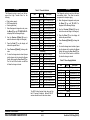
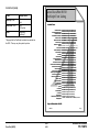
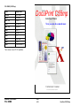
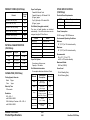
TABLE OF CONTENTS
TITLE
PAGE
INTRODUCTION
About This Manual --------------------------------- ii
Organization ----------------------------------------- ii
How to use This Manual --------------------------iii
Reference Symbology -----------------------------iii
SERVICE CALL PROCEDURES
Contents ------------------------------------------- 1-1
STATUS INDICATOR RAPS
Contents ------------------------------------------- 2-1
IMAGE QUALITY RAPS
Contents ------------------------------------------- 3-1
REPAIR/ADJUSTMENT PROCEDURES
Contents ------------------------------------------- 4-1
PARTS LIST SECTION
Contents ------------------------------------------- 5-1
GENERAL PROCEDURES/INFORMATION
Contents ------------------------------------------- 6-1
WIRING DATA
Contents ------------------------------------------- 7-1
2/99
DocuPrint C55/C55mp/[NC60]
i
TABLE OF CONTENTS
INTRODUCTION
ABOUT THIS MANUAL
Section 1 - SERVICE CALL PROCEDURES
This manual is part of a multinational
documentation
system
which
includes
Training.
This section contains the following:
This manual contains information that applies
to:
•
•
•
•
USCO
XE
XCL
ACO
This service manual covers both the C55 and
NC60 product families.
Unique NC60 directions will be given in [ ]s.
For example:
Press the On Line [0] key.
The On Line key is unique to the C55 family
and the [0] key is unique to the NC60.
If the entire procedure is unique to a product
family, it will be noted at the top of the page
and in the footer at the bottom of the page.
“USCO” references apply to 115 Volt printers.
“XE” references apply to 220/240 Volt printers.
“Dry Ink” means the same as “Toner” and
“Tag” means the same as “Mod”.
ORGANIZATION
This manual is divided into seven sections
organized as follows:
A Publications comment sheet is provided at
the end of this manual.
•
•
•
•
•
•
Call Flow Instructions
Initial Actions
System Checks
Every Call Activities
Scheduled Maintenance
Final Action
Section 2 - STATUS INDICATOR REPAIR
ANALYSIS PROCEDURES (RAPs)
This section contains the Repair Analysis
Procedures (RAPs) necessary to repair faults
other than image quality faults.
Section 3 - IMAGE QUALITY REPAIR
ANALYSIS PROCEDURES (RAPs)
Call Flow
This section contains the Repair Analysis
Procedures (RAPs) necessary to repair image
quality faults.
The call flow chart shows you how to conduct
the service call.
Section 4 - REPAIR/ADJUSTMENT
PROCEDURES
Initial Actions
This section contains the Repair and
Adjustment procedures for the printer. All
unique procedures will be identified as follows:
The initial actions suggests how to collect data
necessary to proceed with the service call.
System Checks
The System Checks procedures details the
steps for effective repair and verification of
repair of problems found in Initial Action.
Every Call Activities
These are cleaning and maintenance activities
which are performed on every call.
Scheduled Maintenance
Scheduled Maintenance consists of checking
the life remaining on the CRUs.
Final Action
Final Action ensures that image quality is
acceptable, and that printer performance and
appearance is satisfactory.
Details are
included for completing administrative tasks
and closing out the service call.
• USCO
• XE
Section 5 - PARTS LIST
This section contains exploded view drawings
and referenced replaceable parts lists for the
Printer.
Section 6 - GENERAL PROCEDURES
This section contains Diagnostic procedures,
Menus, Product Specifications, ESS/IOT test
patterns, and other General Procedures.
Section 7 - WIRING DATA
This section contains Block Schematic
Diagrams (BSDs), Plug/Jack/PWB Location
Diagrams and wiring diagrams.
2/99
INTRODUCTION
ii
DocuPrint C55/C55mp/[NC60]
HOW TO USE THIS MANUAL
Section 1, Service Call Procedures will direct
you to each section of the manual necessary
to perform a service call.
You will begin with Initial Actions which
suggest how to collect problem symptoms and
evidence to be used in the next section, the
System Checks Section.
Descriptions of commonly used graphic
symbols are included in order to aid
troubleshooting when using the circuit
diagrams.
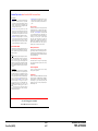
This symbol, used with a number,
indicates that the actual number may
be equal to or very near the value of
the designated number.
Switches/Relays
Triac, used to switch AC power.
Safety interlock switch, circuit closed.
Led/Phototransistor Sensor.
Switch/relay with momentary contacts
shown normally open.
Switch/relay with momentary contacts
shown normally closed.
REFERENCE SYMBOLOGY
Reference Symbology provides supportive
data for Repairs, Adjustments, and the RAPs.
The symbols that refer to this supportive data
are shown in the paragraphs that follow.
Note:
1
MOT
Miscellaneous Symbols
GND
A flag that identifies a wire that has
been referred to in the text.
2
[ 8-2 ]
PL 2.4 (example)
In the example above, the parts list reference
and the exploded view drawing would be found
in Section 5 on sub-section 2.4.
Indicates a Diagnostic Code used to
check a particular component.
Identifies a test point, test hole or test
stake on a PWB.
A
Motor.
Thermistor Bead, used to sense
temperature.
Magnetically actuated Switch.
This symbol is used to refer to notes,
usually found on the same page.
Parts Lists
Light Emitting Diode (LED).
Safety interlock switch, circuit open.
Details in the System Checks are designed to
assist you in classifying, repairing and verifying
the repair of the problem. From here, you may
be directed to any of the other six sections of
the service manual depending on the
symptoms observed and the results of
suggested tests. After a repair has been
verified (or during a repair activity) instructions
are included to direct you into Every Call
Activities.
A/D
A Driver which is used to switch on
DC Components.
Analog to Digital Converter.
RL
Relay
Solenoid
Auditron/Key Counter connection.
2/99
DocuPrint C55/C55mp/[NC60]
iii
INTRODUCTION
Signal Continuation/Flow
Indicates the continuation of a signal
line interrupted in a horizontal
direction.
Represents the continuation of a
standby power line interrupted in the
vertical direction. In all cases, the
supply is from Standby Power
Tag Identification
47
47
47
47
Indicates a feedback signal.
This WITH TAG Symbol is used to
identify the components or configuration that are part of a printer change
covered by the Tag number.
This WITHOUT TAG Symbol is used
to identify the components or
configuration that are not part of a
printer change covered by the Tag
number
Indicates a common splice of wires.
P/J57
6
Indicates a common splice of wires at
a pin.
Indicates the direction of signal flow.
Indicates that the wire continues to
the adjacent page.
2/99
INTRODUCTION
iv
DocuPrint C55/C55mp/[NC60]
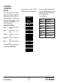
1. SERVICE CALL PROCEDURES
TITLE
PAGE
CALL FLOW---------------------------------------1-2
INITIAL ACTION ---------------------------------1-3
SYSTEM CHECKS ------------------------------1-3
EVERY CALL ACTIVITIES --------------------1-4
SCHEDULED MAINTENANCE ---------------1-4
FINAL ACTION -----------------------------------1-5
DocuPrint C55/C55mp/[NC60]
2/99
SERVICE CALL PROCEDURES
1-1
SECTION CONTENTS
CALL FLOW
INITIAL ACTION
This step is used to gather information about the
reason for the call, to determine the machine
condition, and to run print samples.
SYSTEM CHECKS
This step is used to suggest a direction for using the
information, obtained during Initial Action. You can
then repair and verify the repair of the problem. This
step may also provide information to assist in the
identification of new problems and suggest actions to
take to repair/resolve them.
EVERY CALL ACTIVITIES
This step consists of every call cleaning and
maintenance activities.
SCHEDULED MAINTENANCE
This step is used to check the life remaining on the
CRU’s.
FINAL ACTIONS
This step is used to ensure that the print quality, the
printer performance, and the printer appearance is
satisfactory. It will also provide direction to help
complete administrative tasks.
SERVICE CALL PROCEDURES
2/99
CALL FLOW
1-2
DocuPrint C55/C55mp/[NC60]
INITIAL ACTION
SYSTEM CHECKS
Purpose
Purpose
To suggest how to gather information about
the service call, the machine condition, and to
direct the user through the call.
To suggest a direction for effective repair and
verification of repair of problems found in Initial
Action.
PROCEDURE
PROCEDURE
1. Ask the customer to describe the problem
that causes the service call and the job
being run when the problem occurred.
1. Select the appropriate situation from a-g
below, then diagnose and repair the
problem.
2. Inspect any rejected prints for evidence of
defects.
3. Switch the printer power Off/On and check
for and note/record any fault codes in the
Control Panel Display.
4. Examine the Machine Service Log (under
the Left Side Cover) for previous problems
or activities that may be related to this
service call.
5. Go to (SYSTEM CHECKS).
a. Replace any obviously broken parts.
b. If this is an Image Quality problem, go
to IQ1 Image Quality Entry RAP in
Section 3.
c.
If there is a Fault Code, go to Section
2 Table of Contents. Locate and
perform the RAP associated with the
Fault Code.
d. If there is NO fault code associated
with the problem, go to Section 2
Table of Contents.
Locate and
perform the RAP which most closely
matches the problem described by the
customer.
e. If the problem is not repeatable,
operate the printer in the same job
conditions the customer used and
recheck for a problem in the
categories listed here.
DocuPrint C55/C55mp/[NC60]
f.
If the problem still is not reproduced,
check the printer Fault History.
(C55/C55mp)
Off Line, Menu, then scroll to
<SERVICE>,
<ERROR
LOGS>,
<FAULT HISTORY>. Scroll through
the Fault History and note any
repeating faults. Refer to the RAP for
these fault codes in Section 2 and
read the fault code description to see
if the code relates to the customer
problem. If so, perform the RAP
[NC60]
Menu Up until Print Menu. Item Up
until Fault History then press Enter.
Look through the Fault History and
note any repeating faults. Refer to the
RAP for these fault codes in Section 2
and read the fault code description to
see if the code relates to the customer
problem. If so, perform the RAP.
g. If none of the above situations applies
go to EVERY CALL ACTIVITIES.
2. Verify that the problem is corrected and go
to EVERY CALL ACTIVITIES.
2/99
SERVICE CALL PROCEDURES
1-3
INITIAL ACTION/SYSTEM CHECKS
EVERY CALL ACTIVITIES
SCHEDULED MAINTENANCE
Purpose
Purpose
To list service activities required for specific
subsystems.
To check the life remaining on the CRUs.
PROCEDURE
1. Check the life of the Customer Replaceable Units (CRUs).
1. Open the printer and Clean the Charge
Scorotron using the Scorotron cleaner.
2. Clean the toner loading area.
3. Remove the Following:
a. Print Drum Module. (GP I)
b. Color Developer Module. (GP 2)
c.
Black Developer Module (GP 3)
d. Toner Collector. (GP 4)
4. Vacuum the Drum, Developer, and Toner
Collector areas.
5. Replace the Toner Collector if required.
6. Reinstall the following:
a. Black Developer Module (GP 3)
b. Color Developer Module. (GP 2)
c.
PROCEDURE
a. (C55/C55mp)
Enter the Off Line mode, press Menu
and scroll to <MAINTENANCE>.
[NC60]
Menu Up until Service Menu, Item Up
until CRU Usage, Value Up to see %
remaining on the CRUs.
b. Check the life remaining on the
following:
• Black Developer Cartridge.
• Color Developer Cartridge.
• Print Drum.
• Fuser Module.
2. If any of the CRUs are near end of life,
notify the customer.
Print Drum Module. (GP I)
d. Toner Collector. (GP 4)
7. Use Film Remover to clean the Feed
Rollers. Do not rotate the Feed Rollers
more than 270° while cleaning. Apply
Rubber restore if available.
8. Check the Transfer Drum Nip Adjustment
(ADJ 11.1)
9. Wipe the outside of the printer.
SERVICE CALL PROCEDURES
EVERY CALL ACTIVITIES/
SCHEDULED MAINTENANCE
2/99
1-4
DocuPrint C55/C55mp/[NC60]
FINAL ACTION
Wrap-Up Procedure
Purpose
1. Record your service activities in the
service log.
To ensure the image quality is acceptable,
printer performance and appearance is
satisfactory and to complete administrative
tasks.
PROCEDURE
1. Install/close all covers and doors.
2. Run the Print Quality sample set.
a. (C55/C55mp)
Enter the Off Line mode, press Menu
and scroll to <SERVICE>. Select
<TEST PATTERNS>, and print the
PQ set.
[NC60]
Menu Up until Service Menu, Item
Down until Print PQ Set and press
Enter.
2. Record the Total meter reading (from the
Diagnostic Test Pattern) in the service log.
3. Record the ESS software level (from the
Diagnostic Test Pattern) in the service log.
4. (C55/C55mp)
(Off Line, Print, Settings). Record the NIC
software level (from the Settings page) in
the service log.
5. Put the Printer PQ set and service log into
the service log folder.
NOTE: It is very important to save the PQ
set. There is information on the Diagnostic
sheet (Toner Concentration setpoints) which
will be needed if the NVM is reset or the PCU
PWB is replaced.
3. If possible, ask the customer to print one
of their representative prints to examine
and comment on.
DocuPrint C55/C55mp/[NC60]
2/99
SERVICE CALL PROCEDURES
1-5
FINAL ACTION
Notes:
SERVICE CALL PROCEDURES
2/99
NOTES
1-6
DocuPrint C55/C55mp/[NC60]
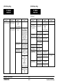
2. STATUS INDICATOR RAPs
TITLE
PAGE
TITLE
PAGE
TROUBLESHOOTING TIPS ------------------2-2
J1-ADD YELLOW TONER------------------- 2-15
C1-CHECK TRAY 1 -----------------------------2-3
J2-ADD MAGENTA TONER ---------------- 2-16
C2-CHECK TRAY 2 -----------------------------2-3
J3-ADD CYAN TONER----------------------- 2-17
E1-TRAY 1 JAM----------------------------------2-4
J4-ADD BLACK TONER --------------------- 2-18
E2-TRAY 2 JAM ---------------------------------2-5
J5-REPLACE COLOR DEVELOPER
CARTRIDGE -------------------------------- 2-19
E3-BYPASS JAM --------------------------------2-5
E4-INPUT JAM -----------------------------------2-6
E5 FUSER JAM ----------------------------------2-7
E6-DRUM JAM -----------------------------------2-8
E7-PRINT DRUM JAM------------------------ 2-10
E8-OUTPUT JAM ------------------------------ 2-10
E9-CLOSE PRINTER ------------------------- 2-10
EA-COLOR DEV. MISINSTALLED -------- 2-11
EB-BLACK DEV. MISINSTALLED --------- 2-11
J6-REPLACE BLACK DEVELOPER
CARTRIDGE -------------------------------- 2-19
J7-TONER COLLECTOR FULL------------ 2-20
TITLE
PAGE
W1-COLOR DEVELOPER MODULE
(NEAR END OF USE) ------------------- 2-28
W2-BLACK DEVELOPER MODULE
(NEAR END OF USE) ------------------- 2-28
W3-PRINT DRUM (NEAR
END OF USE) ----------------------------- 2-28
W4-FUSER MODULE
(NEAR END OF USE) ------------------- 2-29
W5-FUSER OIL BOTTLE/PAD
(NEAR END OF USE) ------------------- 2-29
J8-REPLACE PRINT DRUM ---------------- 2-20
J9-REPLACE FUSER MODULE ----------- 2-20
OF1 DEAD PRINTER RAP ---------------- 2-30
JA-REPLACE OIL/PAD----------------------- 2-21
OF2 CONTROL PANEL RAP ------------- 2-32
T0-FUSER THERMISTOR ERROR ------- 2-21
OF3 TRAY 1 PAPER SIZE
SENSING RAP ------------------------- 2-35
T1- UNDER TEMPERATURE -------------- 2-22
U0-IOT ROM ERROR ------------------------ 2-23
OF4 TRAY 2 PAPER SIZE
SENSING RAP ------------------------- 2-36
U1-IOT RAM ERROR------------------------- 2-24
OF5 LOAD PAPER RAP-------------------- 2-37
U2-IOT NVM RAM ERROR ----------------- 2-24
OF6AESS RAP (C55/C55mp) -------------- 2-38
U3-IOT/ESS COMMUNICATION
ERROR ------------------------------------- 2-24
OF6BESS RAP [NC60]----------------------- 2-39
H1-HARD DISK ERROR --------------------- 2-13
H2-HARD DISK CONTROLLER
ERROR ------------------------------------- 2-13
U4-OPTICS FAULT --------------------------- 2-25
OF7 ESS BOOT FAILURE
ERROR CODES [NC60] ------------- 2-40
U5-POLYGON MOTOR FAULT ------------ 2-25
OF8 ARCING RAP --------------------------- 2-41
EC-PRINT DRUM MISINSTALLED-------- 2-11
F1-DISK ERROR (FLOPPY) ---------------- 2-12
F2-DISK I/O ERROR (FLOPPY) ----------- 2-12
F3-ACTION FAILED (FLOPPY) ------------ 2-12
H3-HARD DISK FULL------------------------- 2-14
H4-FORMAT HARD DRIVE ----------------- 2-14
DocuPrint C55/C55mp/[NC60]
T2- OVER TEMPERATURE ---------------- 2-23
U6-MOTOR FAULT (DEVELOPER) ------ 2-26
U7- MOTOR FAULT (MAIN) ---------------- 2-27
2/99
STATUS INDICATOR RAPs
2-1
SECTION CONTENTS
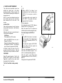
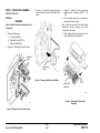
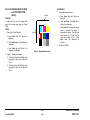
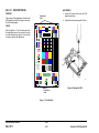
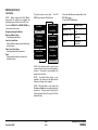
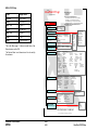
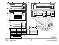
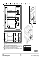
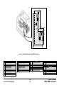
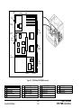
TROUBLESHOOTING TIPS
The following are some general troubleshooting tips and hints which will help you
locate components and test points.
1. The procedures for entering, exiting and
using the C55/C55mp/[NC60] diagnostic
programs can be found in Section 6,
General Procedures. Refer to the Table of
Contents found on page 6-1 for the
specific program.
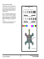
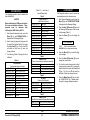
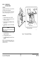
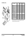
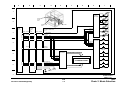
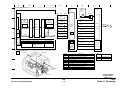
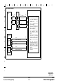
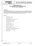
2. Figure 2-1 on the right is also located in
Section 6 and shows the location of the
input electrical components in the printer.
It is especially helpful when using the
Switch Scan program. Refer to this figure
if you are unsure of input component
location. The BSDs in Section 7 may also
prove helpful when locating the various
electrical components.
OIL
SENSOR
TRANSPARENCY
JAM SENSOR
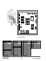
Location
Figure
CN100’s
PCU PWB/ESS PWB
7-1
CN200’s
Cassette PWB
7-4
CN300’s
Connector PWB
7-2
CN400’s
Control Panel PWB
7-2
CN700’s
LVPS PWB
7-2
CN800’s
HVPS PWB
7-3
+24 V
INTERLOCK
SWITCH
CLEANER JAM
SWITCH
TRANSPARENCY
SENSOR
PHOTORECEPTOR
DETECT
TRANSFER DRUM
HOME SENSOR
REGISTRATION
SENSOR
BYPASS SWITCH
WASTE TONER
BOTTLE SENSOR
PS0
TEMPERATURE/
HUMIDITY SENSOR
PS1 PS2 PS3
PS4
TRAY EMPTY
SENSOR
T2 TRAY EMPTY T2
SENSOR
S0
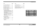
3. The Connectors can be located in
Section 7. Refer to Section 7 Table of
contents on page 7-1. The table below
shows the location of the most common
connectors:
Connector
Numbers
EXIT SENSOR
GAMMA
SENSOR
T2
S1
T2
S2
T2
S3
T2
S4
Figure 2-1. Input Component Location
STATUS INDICATOR RAPs
2/99
TROUBLESHOOTING TIPS
2-2
DocuPrint C55/C55mp/[NC60]
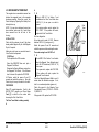
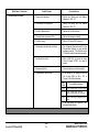
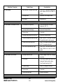
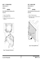
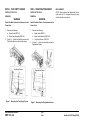
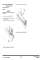
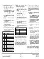
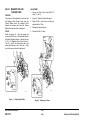
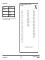
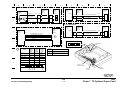
C1 CHECK TRAY 1 RAP
C2 CHECK TRAY 2 RAP
Cassette 1 is not in the printer.
Cassette 2 is not in the printer.
INITIAL ACTION
INITIAL ACTION
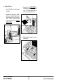
Load paper and insert Cassette 1 into the
printer.
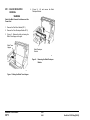
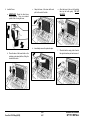
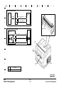
Move the length stop to the 11 inch position
(Figure 2-2), load paper, and insert Cassette 2
into the printer.
Switch the power off wait 10 seconds and
switch the power on. Recheck for the fault.
PROCEDURE
Enter IOT normal diagnostics. Scroll to the
SWITCH SCAN program and select Scan Row
01, Press Form Feed [1].
Remove Cassette 1. Manually make and
break Paper Size Sensor 0 while observing the
Cyan LED. (Sensor 0 is the first one on the
left when viewed from the front of the printer.)
Switch the power off wait 10 seconds and
switch the power on. Recheck for the fault.
Remove Cassette 2. Manually make and
break T2 Paper Size Sensor 0 while observing
the Cyan LED.
Y
Y
If no short is found, replace the PCU
PWB. If the problem still exists, replace
the Cassette PWB.
Figure 2-2. Length Stop Location
Enter IOT normal diagnostics. Scroll to the
SWITCH SCAN program and select Scan Row
03. Press Form Feed [1].
The Cyan LED switches on and off.
Go to BSD 7.2 in Section 7 and troubleshoot the Paper Size 0 Sensor signal
(CN107-8) for a short to ground.
14"
PROCEDURE
The Cyan LED switches on and off.
N
10.5" 11", A4
N
Refer to BSD T2, 7.2 in Section 7 and
check the following:
• T2 Paper Size 0 Sensor signal CN1091 for an open.
• +5 VDC CN109-5
Check for a broken Sensor Flag on the Tray 1
Cassette.
If no problem is found, replace the PCU
PWB. If the problem still exists, replace
the T2 Cassette PWB.
If the problem still exists, replace the PCU
PWB. If the problem still exists, replace the
Cassette PWB.
Check for a broken Sensor Flag on the Tray 2
Cassette.
If the problem still exists, replace the PCU
PWB. If the problem still exists, replace the
Cassette PWB.
DocuPrint C55/C55mp/[NC60]
2/99
STATUS INDICATOR RAPs
2-3
C1, C2
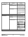
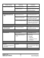
E1 TRAY 1 JAM RAP
A
Paper fed from Tray 1 did not reach the
Registration Sensor.
The Black LED switches on and off.
Y
INITIAL ACTION
PROCEDURE
Obstructions in the paper path.
Dirty Feed Rolls.
Dirty Drive Rollers.
Mechanical drive problem.
Enter IOT normal diagnostics. Scroll to the
SWITCH SCAN program and select Scan Row
00. Press Form Feed [1].
Remove the paper cassette. Scroll to the
MOTOR TEST program. Press Form Feed
[1] to switch on the motors while observing the
Paper Feed Motor.
The Paper Feed Motor is rotating normally.
Y
N
Go to BSD 7.3 in Section 7 and troubleshoot the +24 VDC Interlocked (CN111-5)
and Paper Feed Motor for an open. If the
motor was noisy, check the clock lines.
If the lines are OK, replace the PCU PWB.
If the problem still exists, replace the
Paper Feed Motor.
N
Go to BSD 8.1 in Section 7 and troubleshoot the Registration Sensor signal, +5
VDC and GND (CN102-9, 7, 8) for an
open.
Exit from diagnostics.
If no open exists, replace the PCU PWB.
If the problem still exists, replace the
Registration Sensor.
Make one print while monitoring the meter.
Set up the meter to read +24 VDC. Measure
between CN101-5 (+) and ground (− ).
The meter swings from +24 VDC to 0.
Y
N
Go to BSD 7.4 in Section 7 and troubleshoot the Feed Solenoid signal, and +24
VDC Interlocked (CN101-5, 3) for an
open.
Remove the cassette and actuate and
deactuate the Tray Empty Sensor while
observing the Black LED.
A
Check for a mechanical problem with the feed
clutch.
Close the Printer.
The Magenta LED switches on and off.
Press Media Server [2]. Select Scan Row 01.
Press Form Feed [1].
If no open exists, replace the PCU PWB. If
the problem still exists, replace the Paper
Feed Solenoid.
Exit from the SWITCH SCAN program.
Open the Printer. Actuate and deactuate the
Registration Sensor while observing the
Magenta LED.
Y
C
If no short exists, replace the PCU PWB. If
the problem still exists, replace the Tray
Empty Sensor.
Switch the power off wait 10 seconds and
switch the power on. Recheck for the fault.
•
•
•
•
N
Go to BSD 7.1 in Section 7 and troubleshoot the Tray Empty Sensor signal
(CN102-6) for a short to ground.
Remove the cassette and check that the paper
is loaded correctly and is in good condition.
Check the following:
B
B
C
STATUS INDICATOR RAPs
2/99
E1
2-4
DocuPrint C55/C55mp/[NC60]
E2 TRAY 2 JAM RAP
A
E3 BYPASS JAM RAP
Paper fed from Tray 2 did not reach the
Registration Sensor.
Exit from diagnostics.
Paper fed from the Bypass Tray did not reach
the Registration Sensor.
INITIAL ACTION
Set up the meter to read +24 VDC. Measure
between CN109-8 (+) and ground (− ).
Remove the cassette and check that the paper
is loaded correctly and is in good condition.
Check the position of the rear stop.
Make one print while monitoring the meter.
Make sure that Tray 1 is pushed all the way in.
Y
The meter swings from +24 VDC to 0 and
back to +24.
Switch the power off wait 10 seconds and
switch the power on. Recheck for the fault.
Go to BSD T2 7.3 in Section 7 and
troubleshoot the T2 Feed Solenoid signal,
and +24 VDC Interlocked (CN109-8, 7) for
an open.
PROCEDURE
Try to run a print from Tray 1.
If no open exists, replace the PCU PWB. If
the problem still exists, replace the T2
Feed Solenoid.
The print feeds OK from Tray 1.
Y
N
Go to E1 TRAY 1 JAM RAP.
Check the following:
•
•
•
•
Obstructions in the paper path.
Dirty Feed Rolls.
Dirty Drive Rollers.
Mechanical drive problem.
N
Measure between CN109-9 (+) and ground
(− ).
Make one print while monitoring the meter.
The meter swings from +24 VDC to 0 and
back to +24.
Y
N
Enter IOT normal diagnostics. Scroll to the
SWITCH SCAN program and select Scan Row
03. Press Form Feed [1].
Go to BSD T2 7.4 in Section 7 and
troubleshoot the T2 Drive Clutch signal
(CN109-9) for an open.
Remove cassette 2. Actuate and deactuate
the Tray 2 Empty Sensor while observing the
Black LED.
If no open exists, replace the PCU PWB.
If the problem still exists, replace the T2
Drive Clutch.
The Black LED switches on and off.
Y
N
INITIAL ACTION
Carefully inspect the bypass opening for
paper.
Switch the power off wait 10 seconds and
switch the power on. Run another print and
recheck for the fault.
PROCEDURE
If paper does not feed from the Bypass but
does feed from Tray 1, check for an
obstruction in the bypass slot.
Check to ensure that the switch is installed
correctly and has not fallen out.
If no paper is loaded in the Bypass when the
E3 occurs, refer to BSD 7.5 in Section 7 and
check the Bypass Switch signal (CN312-2) for
a short to ground.
If no short exists, replace the PCU PWB. If
the problem still exists, replace the Bypass
Switch.
Check for a mechanical problem with the Feed
Clutch and Drive Clutch
Go to BSD T2 7.1 in Section 7 and
troubleshoot the T2 Tray Empty Sensor
signal (CN109-4) for a short to ground.
If no short exists, replace the PCU PWB.
If the problem still exists, replace the Tray
2 Empty Sensor.
A
DocuPrint C55/C55mp/[NC60]
2/99
STATUS INDICATOR RAPs
2-5
E2, E3
E4 INPUT JAM RAP
Paper was on the Registration Sensor too
long.
A
The Cyan LED switches on and off.
Y
Go to BSD 8.4 in Section 7 and troubleshoot the Transparency Sensor signal
(CN311-1) for a short to ground.
INITIAL ACTION
Open the printer and check for any obstruction
in the register roller area.
If no short exists, replace the PCU PWB.
If the problem still exists, replace the
Transparency Sensor.
Switch the power off wait 10 seconds and
switch the power on. Run another print to
recheck for the fault.
Make sure the Grounding Roller is rotating
freely.
Perform the Transfer Drum Nip Adjustment
(ADJ 11.1)
PROCEDURE
Enter IOT normal diagnostics. Scroll to the
SWITCH SCAN program and select Scan Row
00. Press Form Feed [1].
Press Media Server [2]. Select Scan Row 04.
Press Form Feed [1].
The meter swings from +24 VDC to 0 and
back to +24.
Y
N
Go to BSD 7.4 in Section 7 and troubleshoot the Feed Solenoid signal (CN101-5)
for a short to ground.
If no short exists, replace the PCU PWB.
If the problem still exists, replace the Feed
Solenoid.
Remove the paper cassette. Scroll to the
MOTOR TEST program and press Form Feed
[1] to switch on the motors while observing the
Paper Feed Motor.
Set up the meter to read +24 VDC. Measure
between CN101-4 (+) and ground (− ).
The Paper Feed Motor is rotating normally.
Make one print while monitoring the meter.
Y
The meter swings from +24 VDC to 0 and
back to +24.
N
Go to BSD 7.3 in Section 7 and troubleshoot the Paper Feed Motor clock lines.
If the lines are OK, replace the PCU PWB.
If the problem still exists, replace the
Paper Feed Motor.
N
If no short exists, replace the PCU PWB.
If the problem still exists, replace the
Registration Sensor.
Make one print while monitoring the meter.
Close the Printer.
The Magenta LED switches on and off.
Go to BSD 8.1 in Section 7 and troubleshoot the Registration Sensor signal
(CN102-9) for a short to ground.
Set up the meter to read +24 VDC. Measure
between CN101-5 (+) and ground (− ).
Exit from the SWITCH SCAN program.
Open the Printer. Actuate and deactuate the
Registration Sensor while observing the
Magenta LED.
Y
N
B
Exit from diagnostics.
Set up the meter to read +24 VDC. Measure
between CN103-4 (+) and ground (− ).
Make one print while monitoring the meter.
The meter swings from +24 VDC to 0 and
back to +24.
Y
N
Go to BSD 9.16 in Section 7 and troubleshoot the Stripper Solenoid signal and +24
VDC Interlocked (CN103-4, CN303-2,1) for
an open.
Actuate and deactuate the Transparency
Sensor while observing the Cyan LED.
A
Y
N
Go to BSD 8.2 in Section 7 and troubleshoot the Registration Clutch signal and
+24 VDC Interlocked (CN101-4, 1) for an
open.
If no open exists, replace the PCU PWB. If
the problem still exists, replace the
Registration Clutch.
Check the following:
• Obstructions torn paper etc. in the paper
path.
• Mechanical drive problem.
If no open exists, replace the PCU PWB. If
the problem still exists, replace the
Stripper Solenoid.
B
STATUS INDICATOR RAPs
2/99
E4
2-6
DocuPrint C55/C55mp/[NC60]
E5 FUSER JAM RAP
A
B
INITIAL ACTION
Go to BSD 10.2 in Section 7 and troubleshoot the Exit Sensor signal, +5 VDC and
GND (CN308-1, 3, 2) for an open.
Open the Printer and remove the Fuser
Assembly. Check for any obstructions in the
fuser paper path.
If no open exists, replace the PCU PWB.
If the problem still exists, replace the Exit
Sensor.
Paper did not reach the Exit Sensor.
Switch the power off wait 10 seconds and
switch the power on. Run another print to
recheck for the fault.
PROCEDURE
Check the following:
• Obstructions in the paper path.
• Defective stripper fingers.
• Mechanical drive problem.
Enter IOT normal diagnostics. Scroll to the
SWITCH SCAN program and select Scan Row
00. Press Form Feed [1].
Open the Printer, then open the Fuser cover.
Actuate and deactuate the Exit Sensor while
observing the Yellow LED.
The Yellow LED switches on and off.
Y
N
Exit from the SWITCH SCAN program.
Remove the Front Cover and then close the
Printer.
Scroll to the MOTOR TEST program and
press Form Feed [1] to switch on the motors
while observing the Fuser Drive Motor.
The Fuser Drive Motor is rotating normally.
Y
N
Go to BSD 10.1 in Section 7 and troubleshoot the Fuser Drive Motor clock lines.
If the lines are OK, replace the PCU PWB.
If the problem still exists, replace the
Fuser Drive Motor.
• Make sure the Fuser Cover fits correctly.
• Check for a Mechanical problem.
With SCAN ROW 00 still selected, actuate
and deactuate the Bypass Switch while
observing the Cyan LED.
The Cyan LED switches on and off.
Y
N
Go to BSD 10.2 and troubleshoot the
Strobe 2 signal CN103-18 for an open.
If no open exists replace the PCU
PWB.
A
B
DocuPrint C55/C55mp/[NC60]
2/99
STATUS INDICATOR RAPs
2-7
E5
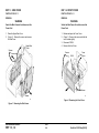
E6 DRUM JAM RAP
Paper is jammed on the Transfer Drum and
could be caused by one of the following:
• Transfer Drum Cleaner not cleaning the
Transfer Drum or resting on the Transfer
Drum during the Print cycle.
• Paper did not reach the Gamma Sensor.
• Paper did not tack to the Transfer Drum and
actuated the Transparency Jam Sensor.
• Paper did not tack to the Transfer Drum
and actuated the Cleaner Jam Switch.
• Arcing between the Charge Scorotron
connectors and the Print Drum.
INITIAL ACTION
Open the Printer and check for torn paper or
an obstruction in the paper path. Check for a
sheet of paper or a transparency actuating the
Transparency Jam Sensor or the Cleaner Jam
Switch.
Check the Toner Collector for “layered” toner
(sand-art effect). If layered toner is present,
refer to OF8 Arcing RAP.
If the problem only occurs when running color
prints, check the Stripper Fingers for binding
or interference.
Open the Printer and position the Transfer
Drum Home Position Sensor flag at the
3 o’clock position. The Lead edge of the white
patch should be at the tips of the stripper
fingers. If not, replace the Transfer Drum.
PROCEDURE
If you see solid development during the copy
quality setup, go the OF8 Arcing RAP.
The Transfer Drum Cleaning Solenoid should
energize and move the Cleaner Assembly
against the Transfer Drum while the patches
are generated during the Copy Quality Setup.
When the Copy Quality Setup is complete the
Transfer Drum Cleaning Solenoid should
deenergize and move the Cleaner Assembly
away from the Transfer Drum.
If the E6 jam occurs before paper is fed and
the patches are not being cleaned the Transfer
Drum Cleaner assembly is not camming into
the cleaning position.
If the machine prints OK when printing black
only but jams (E6) when printing color, it is an
indication that the Transfer Drum Cleaner
assembly is staying cammed against the
Transfer Drum.
The Transfer Drum Cleaning Solenoid and
Transfer Drum Cleaner Assembly are
operating correctly.
Y N
Switch the Printer off. Remove the front cover
and tape the Control Panel up so that you can
view the operation of the Transfer Drum
Cleaning Solenoid.
Switch the Printer on. Observe the Transfer
Drum Cleaning Solenoid and the Cleaner
Assembly.
A
Check that when the solenoid energizes
the camshaft turns 180 degrees and is
stopped by the outer tab on the cleaner
clutch sleeve. Ensure that the solenoid is
tight and the actuator catches the inner tab
when de-energized, and stops the outer
tab when energized. Check for flashing on
the plastic assembly, a bent solenoid
actuator or other things that could interfere
with proper operation. Clean the cams
and the cam followers with film remover to
minimize friction.
Do not attempt to
lubricate these cams. Observe the operation several times and look for smooth,
consistent operation. Do not attempt to
disassemble and adjust the clutch. If the
clutch is defective order the new Cleaner
Clutch Shaft Assembly.
B
STATUS INDICATOR RAPs
2/99
E6
2-8
A
B
Set up the meter to read +24 VDC. Measure
between CN103-3 (+) and ground (− ).
Switch the power off wait 10 seconds and
switch the power on while monitoring the
meter.
The meter swings from +24 VDC to 0
and back to +24.
Y
N
Go to BSD 9.14 in Section 7 and
troubleshoot the Transfer Drum
Cleaning
Solenoid
signal
and
+24 VDC
Interlocked
(CN103-3,
CN316-2, 1) for an open or a short.
If 24 VDC is not available at 316-1 on
the Connector PWB, go to BSD 1 and
troubleshoot the 24 VDC Interlocked
(CN114-1, CN103-1).
Check the Transfer Drum Cleaning
Solenoid and the cleaner assembly for
binding.
If the sheet appears to be stopping at the
Transfer Drum to Print Drum Nip, check the
Transfer Drum Nip Adjustment (ADJ 11.1).
Enter IOT normal diagnostics. Scroll to the
SWITCH SCAN program and select Scan Row
05. Press Form Feed [1].
Open the Printer. Actuate and deactuate the
Transparency Jam Sensor while observing the
Black LED.
The Black LED switches on and off.
Y
N
Check for an obstruction that is keeping the
Transparency Jam Sensor actuator raised.
C
D
DocuPrint C55/C55mp/[NC60]
C
D
E
F
If OK, refer to BSD 9.17 and check the
Transparency Jam Sensor signal CN314-2
for a short to ground.
Set up the meter to read +24 VDC. Measure
between CN103-4 (+) and ground (− ).
Y
If no short exists, replace the PCU PWB.
If the problem still exists, replace the
Transparency Jam Sensor.
Open the printer and remove the Transfer
Discharge Corotron from the left side of the
printer. You will need to squeeze the corotron
handle to release the corotron.
Make one print while monitoring the meter.
The meter swings from +24 VDC to 0 and
back to +24.
Y
Go to BSD 9.16 in Section 7 and troubleshoot the Stripper Solenoid signal and +24
VDC Interlocked (CN103-4, CN303-2, 1)
for an open or a short.
With Scan Row 05 still selected, actuate and
deactuate the Cleaner Jam Switch while
observing the Magenta LED.
If no short or open can be found, replace
the PCU PWB. If the problem still exists,
replace the Stripper Solenoid.
The Magenta LED switches on and off.
Y
N
Check for an obstruction that is keeping
the Cleaner Jam Switch actuated.
If OK, refer to BSD 9.18 and check the
Cleaner Jam Switch signal CN318-2 for a
short to ground.
If no short exists, replace the PCU PWB.
If the problem still exists, replace the
Cleaner Jam Switch.
N
Set up the meter to read +5 VDC. Measure
between CN103-11 (+) and ground (− ).
Switch the power off wait 10 seconds and
switch the power on.
The meter swings from 3.8 VDC to .5 when
the white patch passes in front of the
Gamma Sensor.
Y
Exit from the Switch Scan Program.
Scroll to the MOTOR TEST program and
switch on the motors while observing the
Fuser Drive Motor
If the lines are OK, replace the PCU PWB.
If the problem still exists, replace the
Gamma Sensor.
The Fuser Drive Motor is rotating normally.
Refer to Section 6, GP 9.3 and perform the
Transfer Voltage Check.
N
Go to BSD 10.1 in Section 7 and troubleshoot the Fuser Drive Motor for an open.
If the motor was noisy, check the clock
lines for an open or short
Go to BSD 9.1 in Section 7 and troubleshoot the following for an open or short.
• Black Transfer Lead from the Power
Supply.
• Transfer On Signal (CN106-3).
• Transfer Control Signal (CN106-5).
• Bias Control Signal (CN106-6).
• +24 VDC to Power Supply (CN106-1).
If no wiring problem can be found, replace
the PCU PWB. If the problem still exists,
replace the High voltage Power Supply.
Refer to BSD 9.1 in Section 7 and check the
Charge On Signal (CN106-2) for an open.
Check the following:
• Obstructions in the paper path.
• Dirty Feed Rolls.
• Mechanical drive problem.
N
Go to BSD 8.5 in Section 7 and troubleshoot
the Gamma Sensor, all lines, for an open.
Y
N
The Transfer voltage is within specification.
F
If the lines are OK, replace the PCU PWB.
If the problem still exists, replace the
Fuser Drive Motor.
E
DocuPrint C55/C55mp/[NC60]
2/99
STATUS INDICATOR RAPs
2-9
E6
E7 PRINT DRUM JAM RAP
E8 OUTPUT JAM RAP
E9 CLOSE PRINTER RAP
INITIAL ACTION
Paper was on the Exit Sensor too long.
The Printer is open.
Open the Printer and clear the jam.
INITIAL ACTION
INITIAL ACTION
If problem reoccurs refer to E4 RAP.
We have seen some machines where the
actuator for the Exit Sensor has become stuck
during shipping. When this happens, the
sensor does not change state, and the E8 jam
occurs. If you remove the sensor cover
(PL 2.1) by removing the two screws that
secure it, you can ensure that the actuator is
free and that the sensor is secured in the
proper position in the sensor cover.
Open and reclose the printer.
Open the Printer and remove the Fuser
Assembly. Check for any obstructions in the
fuser paper path.
Switch the power off wait 10 seconds and
switch the power on. Run another print to
recheck for the fault.
PROCEDURE
Enter IOT normal diagnostics. Scroll to the
SWITCH SCAN program and select Scan Row
00. Press Form Feed [1].
PROCEDURE
Enter IOT normal diagnostics. Scroll to the
SWITCH SCAN program and select Scan Row
00. Press Form Feed [1].
Open and close the Printer while observing the
Black LED.
The Black LED switches on and off.
Y
N
Go to BSD 1 (G1) in Section 7 and
troubleshoot the 24 VDC Interlock Switch.
If no open exists, replace the PCU PWB.
If the problem still exists, replace the
24 VDC Interlock Switch.
Replace the PCU PWB.
Open the Printer, then open the Fuser Cover.
Actuate and deactuate the Exit Sensor while
observing the Yellow LED.
The Yellow LED switches on and off.
Y
N
Go to BSD 10.2 in Section 7 and troubleshoot the Exit Sensor signal (CN308-1) for
a short to ground.
If no short exists, replace the PCU PWB.
If the problem still exists, replace the Exit
Sensor.
Check the following:
• Obstructions in the paper path.
• Mechanical drive problem in the feedout
area.
STATUS INDICATOR RAPs
2/99
E7, E8, E9
2-10
DocuPrint C55/C55mp/[NC60]
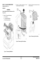
EA COLOR DEV. MISINSTALLED
RAP
EB BLACK DEV. MISINSTALLED
RAP
EC PRINT DRUM MISINSTALLED
RAP
The Color Developer Module was installed
incorrectly or overtoning has occurred.
The Black Developer Module was installed
incorrectly or the contacts are dirty.
The Print Drum Module was installed
incorrectly or is not making a good connection.
INITIAL ACTION
INITIAL ACTION
INITIAL ACTION
Enter IOT normal diagnostics. Scroll to the
TEST PRINT program and press Form Feed
[1] to run a test print. While the print is
running, observe the KT=__, CT=__, MT=__,
YT=__ values.
Remove the Black Developer Module.
Remove then reinstall the Print Drum Module.
Check for binding in the housing.
If any of the three color (C, M, Y) toner
concentration values are below 10, that color
is overtoned. Refer to ADJ 9.1 EA “Tone
Down” Procedure in Section 4.
Check the Developer Module connector to be
sure it is clean.
This problem is usually caused by a poor
connection on the left side of the Print Drum
Module. Three contacts are cammed out
when the Print Drum Module is installed.
These contacts make a connection with the
Drum Link PWB located on the left side of the
Print Drum Module. Check to make sure there
is a good connection and the contacts cam
out.
Check to be sure that the seal has been
removed.
Reinstall the Black Developer Module.
Remove the Color Developer Module.
If the problem persists, check connector
CN107 for a good connection or any loose
wiring before replacing the Black Developer
Module.
Check the Developer Module connector to be
sure it is clean.
If the problem still exists, replace the PCU
PWB.
If the values are NOT too low, continue with
this RAP.
Refer to BSD 9.2 in Section 7 and check the
Drum Detect (H) signal.
If the problem persists, replace the Print Drum
Module.
If the problem still exists, replace the PCU
PWB.
Reinstall the Color Developer Module.
If the problem persists, check connector
CN118 for a good connection or any loose
wiring before replacing the Color Developer
Module.
If the problem still exists, replace the PCU
PWB.
DocuPrint C55/C55mp/[NC60]
2/99
STATUS INDICATOR RAPs
2-11
EA, EB, EC
F1 DISK ERROR (FLOPPY) RAP
F2 DISK I/O ERROR (FLOPPY) RAP
F3 ACTION FAILED (FLOPPY) RAP
The Floppy Disk cannot be read.
The Floppy Disk cannot be read.
The Floppy Disk cannot be accessed.
INITIAL ACTION
INITIAL ACTION
INITIAL ACTION
Note: The Floppy Disk must be a DOS format.
Note: The Floppy Disk must be a DOS format.
Note: The Floppy Disk must be a DOS format.
Load a different floppy and try to read it.
Load a different floppy and try to read it.
Load a different floppy and try to read it.
If the floppy still cannot be read, check the
following for a good connection:
If the floppy still cannot be read, check the
following for a good connection:
If the floppy still cannot be read, check the
following for a good connection:
• CN102 between the Floppy drive and the
ESS. (BSD 13 in Section 7).
• CN102 between the Floppy drive and the
ESS. (BSD 13 in Section 7).
• CN102 between the Floppy drive and the
ESS. (BSD 13 in Section 7).
• CN103 the flat cable between the Floppy
drive and the ESS. (BSD 13 in Section 7).
• CN103 the flat cable between the Floppy
drive and the ESS. (BSD 13 in Section 7).
• CN103 the flat cable between the Floppy
drive and the ESS. (BSD 13 in Section 7).
If the problem still exists, replace the Floppy
Drive before replacing the ESS PWB.
If the problem still exists, replace the Floppy
Drive before replacing the ESS PWB.
If the problem still exists, replace the Floppy
Drive before replacing the ESS PWB.
STATUS INDICATOR RAPs
2/99
F1, F2, F3
2-12
DocuPrint C55/C55mp/[NC60]
H1 HARD DISK ERROR RAP
INITIAL ACTION
The Hard Disk cannot be read.
Switch the power off wait 10 seconds and
switch the power on. This will force the ESS to
retry reading the Hard Disk.
C55/C55mp
NOTE: If no hard disk is installed on this
printer, print a Settings page (Off Line, Print,
Settings) to record the customer network
settings. Tell the customer that you are going
to do a factory reset and they will need to
reinstall the printer on their network. Perform
a Factory Reset (Off Line, Setup, Factory
Reset).
[NC60]
NOTE: If no hard disk is installed on this
printer, print a Config. sheet (Menu Up to
Service Menu, Item Up to Config Sheet,
Enter) to record the customer network
settings. Tell the customer that you are going
to do a factory reset and they will need to
reinstall the printer on their network. Perform
a Factory Reset. Power Off. Press and hold
On Line and Enter. Switch the power on.
Continue holding the On Line and Enter keys
until the display indicates Power On Version
X.XX, then release the keys. This will enable
the Reset Menu. Menu Up until Reset Menu,
Item Up until Factor Defaults, Value Up until
Yes, then press Enter.
DocuPrint C55/C55mp/[NC60]
If the Hard Disk still cannot be read, check the
following:
• (C55/C55mp)
Check the Hard Disk to ensure that the
new Relay Interface PWB is installed.
Look for a small PWB mounted to the left
of the hard drive.
• All Printers, check for a good connection
between the Hard Disk and the ESS
(CN101). (BSD 13 in Section 7).
H2 HARD DISK CONTROLLER
ERROR RAP
The Hard Disk Controller has failed.
INITIAL ACTION
Switch the power off wait 10 seconds and
switch the power on. Retry reading the Hard
Disk.
If the Hard Disk still cannot be read, check the
following for a good connection :
• Between the Hard Disk and the ESS
(CN101). (BSD 13 in Section 7).
If the problem still exists, replace the ESS
PWB.
If the problem still exists, replace the Hard
Disk before replacing the ESS PWB.
2/99
STATUS INDICATOR RAPs
2-13
H1, H2
H3 HARD DISK FULL RAP
H4 REFORMAT HARD DISK RAP
The Hard Disk is full.
The Hard Disk needs to be formatted.
INITIAL ACTION
INITIAL ACTION
Switch the power off wait 10 seconds and
switch the power on. This will force the ESS to
retry reading the Hard Disk.
Switch the power off wait 10 seconds and
switch the power on to retry reading the Hard
Disk.
If the Hard Disk still does not write, have the
customer remove some of the files from the
Hard Disk.
If the H4 occurs again, reformat the hard disk:
STATUS INDICATOR RAPs
2/99
H3, H4
2-14
DocuPrint C55/C55mp/[NC60]
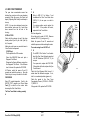
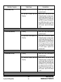
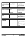
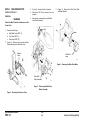
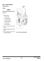
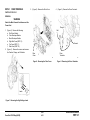
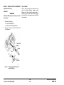
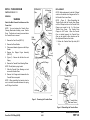
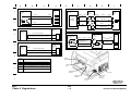
J1 ADD YELLOW TONER RAP
A
The yellow toner concentration sensor has
detected low yellow toner in the yellow
developer assembly. When this occurs, the
Printer will display “Adjusting Print Quality” and
attempt to tone up.
Y
NOTE: If a new color developer housing has
been installed, make sure the 3 seals have
been removed from the left side of the
housing.
INITIAL ACTION
Check with the customer to see if they have
already added Yellow Dry Ink. Add Yellow Dry
Ink, if required.
Adding too much toner can cause the toner to
“cake” and not be dispensed.
(C55/C55mp)
Put the printer in the Off Line mode.
Select the SERVICE Menu and print a
Diagnostic Test Sheet.
Determine the Engine Software version from
the Diagnostic Test Sheet. If the Software
level is Version 66, replace the PCU PWB.
All Printers, switch the power off wait 10
seconds and switch the power on. Allow the
Printer to try to tone up to recheck for the fault.
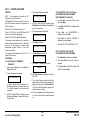
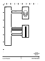
PROCEDURE
Enter IOT normal diagnostics. Scroll to the
MOTOR TEST program and Press Form
Feed [1] to switch on the motors while
observing the Color Toner Motor.
N
Refer to BSD 9.11 in Section 7 and
troubleshoot the Color Toner Motor lines
(CN116-1, 2) for an open or a short to
ground.
If no wiring problem exists, replace the
PCU PWB. If the problem still exists,
replace the Color Toner Motor.
Exit from diagnostics .
Color
Toner
Motor
Y Disp.
Shaft
Set up the meter to read +24 VDC. Measure
between CN115-16 (+) and ground (− ).
Switch the power off wait 10 seconds and
switch the power on while monitoring the meter.
The meter swings from +24 VDC to 0.
Y
N
Go to BSD 9.10 in Section 7 and troubleshoot the Yellow Toner Solenoid signal
and +24 VDC Interlocked (CN115-16, 15)
for an open.
If no open exists, replace the PCU PWB.
If the problem still exists, replace the
Yellow Toner Solenoid.
01/02
Check the Yellow Dispense Shaft to see if it
rotates when the Solenoid energizes. If not,
look for a mechanical problem (gears etc.).
Check the ground to the Yellow Toner
Concentration Sensor (CN118-4 to CN1009-7)
BSD 9.10.
If the ground is OK, replace the PCU PWB.
The Color Toner Motor is rotating normally.
A
DocuPrint C55/C55mp/[NC60]
2/99
STATUS INDICATOR RAPs
2-15
J1
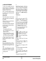
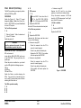
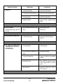
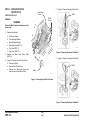
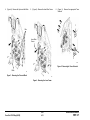
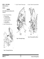
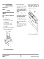
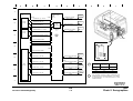
J2 ADD MAGENTA TONER RAP
A
The magenta toner concentration sensor has
detected low magenta toner in the magenta
developer assembly. When this occurs, the
Printer will display “Adjusting Print Quality” and
attempt to tone up.
Y
NOTE: If a new color developer housing has
been installed, make sure the 3 seals have
been removed from the left side of the
housing.
INITIAL ACTION
Check with the customer to see if they have
already added Magenta Dry Ink. Add Magenta
Dry Ink, if required.
Adding too much toner can cause the toner to
“cake” and not be dispensed.
(C55/C55mp)
Put the printer in the Off Line mode.
Select the SERVICE Menu and print a
Diagnostic Test Sheet.
Determine the Engine Software version from
the Diagnostic Test Sheet. If the Software
level is Version 66, replace the PCU PWB.
All Printers, switch the power off wait 10
seconds and switch the power on. Allow the
Printer to try to tone up to recheck for the fault.
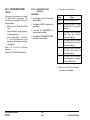
PROCEDURE
Enter IOT normal diagnostics. Scroll to the
MOTOR TEST program and Press Form
Feed [1] to switch on the motors while
observing the Color Toner Motor.
N
Refer to BSD 9.11 in Section 7 and
troubleshoot the Color Toner Motor lines
(CN116-1, 2) for an open or a short to
ground.
If no wiring problem exists, replace the
PCU PWB. If the problem still exists,
replace the Color Toner Motor.
Color
Toner
Motor
Exit from diagnostics.
Set up the meter to read +24 VDC. Measure
between CN115-14 (+) and ground (− ).
M Disp.
Shaft
Switch the power off wait 10 seconds and
switch the power on while monitoring the meter.
The meter swings from +24 VDC to 0.
Y
N
Go to BSD 9.10 in Section 7 and troubleshoot the Magenta Toner Solenoid signal
and +24 VDC Interlocked (CN115-14, 13)
for an open.
If no open exists, replace the PCU PWB.
If the problem still exists, replace the
Magenta Toner Solenoid.
01/02
Check the Magenta Dispense Shaft to see if it
rotates when the Solenoid energizes. If not,
look for a mechanical problem (gears etc.).
Check the ground to the Magenta Toner
Concentration Sensor (CN118-5 to CN100921) BSD 9.10.
If the ground is OK, replace the PCU PWB.
The Color Toner Motor is rotating normally.
A
STATUS INDICATOR RAPs
2/99
J2
2-16
DocuPrint C55/C55mp/[NC60]
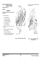
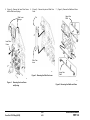
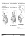
J3 ADD CYAN TONER RAP
A
The cyan toner concentration sensor has
detected low cyan toner in the cyan developer
assembly. When this occurs, the Printer will
display “Adjusting Print Quality” and attempt to
tone up.
Y
NOTE: If a new color developer housing has
been installed, make sure the 3 seals have
been removed from the left side of the
housing.
INITIAL ACTION
Check with the customer to see if they have
already added Cyan Dry Ink. Add Cyan Dry
Ink, if required.
Adding too much toner can cause the toner to
“cake” and not be dispensed.
(C55/C55mp)
Put the printer in the Off Line mode.
Select the SERVICE Menu and print a
Diagnostic Test Sheet.
Determine the Engine Software version from
the Diagnostic Test Sheet. If the Software
level is Version 66, replace the PCU PWB.
All Printers, switch the power off wait 10
seconds and switch the power on. Allow the
Printer to try to tone up to recheck for the fault.
PROCEDURE
Enter IOT normal diagnostics. Scroll to the
MOTOR TEST program and Press Form
Feed [1] to switch on the motors while
observing the Color Toner Motor.
N
Refer to BSD 9.11 in Section 7 and
troubleshoot the Color Toner Motor lines
(CN116-1, 2) for an open or a short to
ground.
If no wiring problem exists, replace the
PCU PWB. If the problem still exists,
replace the Color Toner Motor.
Color
Toner
Motor
Exit from diagnostics.
Set up the meter to read +24 VDC. Measure
between CN115-12 (+) and ground (− ).
Switch the power off wait 10 seconds and
switch the power on while monitoring the meter.
The meter swings from +24 VDC to 0.
Y
C Disp.
Shaft
N
Go to BSD 9.10 in Section 7 and troubleshoot the Cyan Toner Solenoid signal and
+24 VDC Interlocked (CN115-12, 11) for
an open.
If no open exists, replace the PCU PWB.
If the problem still exists, replace the Cyan
Toner Solenoid.
01/02
Check the Cyan Dispense Shaft to see if it
rotates when the Solenoid energizes. If not,
look for a mechanical problem (gears etc.).
Check the ground to the Cyan Toner
Concentration Sensor (CN118-6 to CN100917) BSD 9.10.
If the ground is OK, replace the PCU PWB.
The Color Toner Motor is rotating normally.
A
DocuPrint C55/C55mp/[NC60]
2/99
STATUS INDICATOR RAPs
2-17
J3
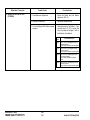
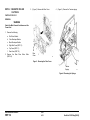
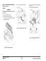
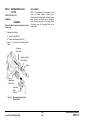
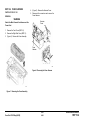
J4 ADD BLACK TONER RAP
A
The black toner concentration sensor has
detected low black toner in the black developer
assembly. When this occurs, the Printer will
dead cycle and attempt to tone up.
NOTE: If a new black developer housing has
been installed, make sure the packing material
has been removed.
Enter IOT normal diagnostics. Scroll to the
MOTOR TEST program and press Form Feed
[1] to switch on the motors. Look through the
hole and switch on the Black Toner Motor by
pressing On Line [0]. Release On Line [0] to
stop the motor. Press Media Server [2] to
stop the test.
INITIAL ACTION
The Motor Runs.
Check with the customer to see if they have
already added Black Dry Ink. Add Black Dry
Ink, if required.
Y
Adding too much toner can cause the toner to
“cake” and not be dispensed.
Check the Black toner hopper to ensure that it
is latched closed and is opening the shutter to
the developer housing.
(C55/C55mp)
Put the printer in the Off Line mode.
Select the SERVICE Menu and print a
Diagnostic Test Sheet.
Determine the Engine Software version from
the Diagnostic Test Sheet. If the Software
level is Version 66, replace the PCU PWB.
All Printers, switch the power off wait 10
seconds and switch the power on. Recheck
for the fault.
PROCEDURE
Remove the Printer Rear Cover. There is a
hole located at the left rear of the printer. This
hole is used to view the gears for the Toner
motor.
NOTE: In the following steps, we will be
operating the Black Toner Motor. Do not allow
the motor to run for over 2 seconds or
overtoning can result.
A
N
Set up the meter to read +24 VDC.
Measure between CN107-13 (+) and
ground (− ). Press Form Feed [1] to
switch on the motors. Press On Line [0]
to switch on the Black Toner Motor.
Release On Line [0] to stop the motor.
Press Media Server [2] to stop the test.
The meter reads approximately 12 VDC
when On Line [0] was pressed.
Y
N
Go to BSD 9.8 in Section 7 and
troubleshoot the Black Toner Motor
lines (CN107-13, 14) for an open.
If the lines are OK, replace the Black
Toner Motor
Check the Black toner box for auger
binding.
Check the ground to the Black Toner
Concentration Sensor (CN107-2 to
CN1001-4) BSD 9.7.
If the ground is OK, replace the PCU
PWB.
Toner should be dispensed, check the Black
toner box for auger binding.
Check the ground to the Black Toner
Concentration Sensor (CN107-2 to CN1001-4)
BSD 9.7.
If the ground is OK, replace the PCU PWB.
STATUS INDICATOR RAPs
2/99
J4
2-18
DocuPrint C55/C55mp/[NC60]
J5 REPLACE COLOR DEVELOPER
CARTRIDGE RAP
NOTE: This code is normally preceded by a
W1 code.
The Color Developer Cartridge is at end of life.
INITIAL ACTION
Check the Color Developer Cartridge life.
A
• Yellow Toner Sense signal for an open or a
short to ground (CN118-8).
• Yellow Toner +5 VDC for an open
(CN118-1).
If all of the above check OK, replace the Color
Developer Cartridge. If the problem still exists,
replace the PCU PWB.
J6 REPLACE BLACK DEVELOPER
CARTRIDGE RAP
NOTE: This code is normally preceded by a
W2 code.
The Black Developer Cartridge is at end of life.
INITIAL ACTION
Check the Black Developer Cartridge life.
(C55/C55mp)
Press On Line, then press Menu, use Next to
scroll to the MAINTENANCE menu, press
Enter. Use Next to scroll to COLOR DEV
CART, press Enter.
(C55/C55mp)
Press On Line, then press Menu, use Next to
scroll to the MAINTENANCE menu, press
Enter. Use Next to scroll to BLACK DEV
CART, press Enter.
[NC60]
Press Menu Up until Service, Item Down until
CRU Usage. Press Value Up to scroll to the
Color Dev. Cart.
[NC60]
Press Menu Up until Service, Item Down until
CRU Usage. Press Value Up to scroll to the
Black Dev. Cart.
Check the % remaining on the Color
Developer Cartridge. If the cartridge is at end
of life, notify the customer and have them
install a new Color Developer Cartridge.
Check the % remaining on the Black
Developer Cartridge. If the cartridge is at end
of life, notify the customer and have them
install a new Black Developer Cartridge.
PROCEDURE
PROCEDURE
Check the developer drive motor, belts and
gears to ensure that they are rotating.
If the J6 code does not clear when a new
Black Developer Cartridge is install, go to BSD
9.7 and check the New Developer Sense
signal (CN107-3) for an open or short.
If the J5 code does not clear when a new Color
Developer Cartridge is install, go to BSD 9.10
and check the New Developer Sense signal
(CN118-7) for an open or short to ground.
If the J6 code exists even though the Black
Cartridge has not reached end of life refer to
BSD 9.7 and check the following:
If the J5 code exists even though the Color
Cartridge has not reached end of life refer to
BSD 9.10 and check the following:
• Black Toner Sense signal for an open or a
short to ground (CN107-4).
• Black Toner +5 VDC for an open
(CN107-1).
• Cyan Toner Sense signal for an open or a
short to ground (CN118-10).
• Cyan Toner +5 VDC for an open (CN118-3).
• Magenta Toner Sense signal for an open or
a short to ground (CN118-9).
• Magenta Toner +5 VDC for an open
(CN118-2).
A
DocuPrint C55/C55mp/[NC60]
If all of the above check OK, replace the Black
Developer Cartridge. If the problem still exists,
replace the PCU PWB.
2/99
STATUS INDICATOR RAPs
2-19
J5, J6
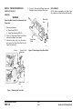
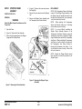
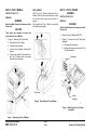
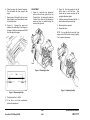
J7 TONER COLLECTOR FULL RAP
J8 REPLACE PRINT DRUM RAP
J9 REPLACE FUSER MODULE RAP
The Toner Collector is full or not installed
correctly.
The Print Drum is at end of life, is not in place,
or is not installed correctly.
The Fuser is at end of life.
INITIAL ACTION
NOTE: This code is normally preceded by a
W3 code.
Remove the Toner Collector and ensure that it
is not full.
Check to ensure that the channel that the
sensor “looks” through is not blocked with
toner.
Reinstall the Toner Collector.
PROCEDURE
Enter IOT normal diagnostics. Scroll to the
SWITCH SCAN program and select Scan Row
02. Press Form Feed [1].
Open the Printer. Remove and reinstall the
Toner Collector while observing the Yellow
LED.
The Yellow LED switches on and off
Y
N
Go to BSD 9.21 in Section 7 and troubleshoot the Waste Toner Sensor signal,
+5 VDC, and GND (CN102-3, 1, 2) for an
open.
If no open exists, replace the PCU PWB.
If the problem still, exists replace the
Waste Toner Sensor.
Install a new Toner Collector.
NOTE: This code is normally preceded by a
W4 code.
INITIAL ACTION
INITIAL ACTION
Check the Fuser Cartridge life.
Check the Print Drum Cartridge life.
(C55/C55mp)
Press On Line, then press Menu, use Next to
scroll to the MAINTENANCE menu, press
Enter.
Use Next to scroll to FUSER
MODULE, press Enter.
(C55/C55mp)
Press On Line, then press Menu, use Next to
scroll to the MAINTENANCE menu, press
Enter. Use Next to scroll to PRINT DRUM,
press Enter.
[NC60]
Press Menu Up until Service, Item Down until
CRU Usage. Press Value Up to scroll to the
Print Drum.
Check the % remaining on the Print Drum
Cartridge. If the cartridge is at end of life,
notify the customer and have them install a
new Print Drum Cartridge.
PROCEDURE
If the J8 code does not clear when a new Print
Drum Cartridge is installed, go to BSD 9.2 and
check the New Drum Detect signal
(CN107-15) for an open or short to ground.
Also check +5 VDC (CN107-17) for an open.
If the J8 code exists even though the Print
Drum Cartridge has not reached end of life,
refer to BSD 9.2 and check the Drum Detect
signal (CN107-19).
[NC60]
Press Menu Up until Service, Item Down until
CRU Usage. Press Value Up to scroll to the
Fuser Module.
Check the % remaining on the Fuser Module.
If the module is at end of life, notify the
customer and install a new Fuser Module.
PROCEDURE
If the J9 code does not clear when a new
Fuser Module is install, go to BSD 10.5 and
check the New Fuser Detect signal (CN103-8,
CN306-4) for an open or short to ground. Also
check +5 VDC (CN306-1) for an open.
If all of the above check OK, replace the Fuser
Module. If the problem still exists, replace the
PCU PWB.
If all of the above check OK, replace the Print
Drum Cartridge. If the problem still exists,
replace the PCU PWB.
STATUS INDICATOR RAPs
2/99
J7, J8, J9
2-20
DocuPrint C55/C55mp/[NC60]
JA REPLACE OIL/PAD RAP
PROCEDURE
T0 THERMISTOR ERROR RAP
The Oil/Pad needs to be replaced.
Enter IOT normal diagnostics. Scroll to the
SWITCH SCAN program and select Scan Row
05. Press Form Feed [1].
The Fuser Thermistor readings are out of
range, the Fuser is missing, or the Fuser is not
seated correctly.
Open the Printer and remove the Fuser
Assembly.
INITIAL ACTION
INITIAL ACTION
Check the Oil Bottle and sump. If required,
replace the Wiper Roll and Oil Bottle. If this
code persists after a new Oil Bottle is installed
or the Oil is OK, continue with this RAP.
Paper dust and other contaminants can cause
the fuser oil to get cloudy and solidify causing
the ball that triggers the Low Oil Sensor to
stick. When low oil is detected, the printer will
stop and the fuser will be powered off after 50
prints to prevent Fuser damage. If the fuser
has the contamination described above, the
ball could be stuck in a position that will
prevent the fuser from warming up.
Check to ensure the fuser sump has oil in it.
There have been some reported instances of
defective oil bottles failing to dispense oil into
the sump.
Ensure that the valve stem on the oil bottle is
not bent or off center. A bent stem will not
engage the plunger in the sump correctly.
If the sump is full, check to see if the ball is
stuck in the bottom of the channel. If it is, you
may be able to correct the problem by
removing the rubber stopper in the tank above
the ball and using a scribe or screwdriver to
loosen the ball.
NOTE: This is only a temporary fix. You
should have the customer order a new fuser
assembly.
If in your judgment this is a
premature failure, follow the applicable
warranty replacement procedures.
Actuate and deactuate the Oil Sensor while
observing the Cyan LED.
The Cyan, LED switches off and on.
Y
N
With Scan Row 05 still selected, actuate
and deactuate the Cleaner Jam Switch
while observing the Magenta LED.
NOTE: During the following check be careful
not to tip the Fuser.
Remove the Fuser Module and check the
condition of the Fuser Connectors.
Check the operation of the shutter that covers
the fuser connectors.
Reinstall the Fuser Module.
The Magenta, LED switches off and on.
Switch the power off wait 10 seconds and
switch the power on. Recheck for the fault.
Y
N
PROCEDURE
Refer to BSD 10.4 and check the
Strobe 1 signal CN103-19 for an open.
Set up the meter to read +5 VDC. Measure
between CN103-9 (+) and ground (− ).
If no open exists replace the PCU
PWB.
When the fuser is cold, the reading should be
around 0.1 VDC. When the fuse is hot, the
reading should be approximately 3.5 VDC.
Refer to BSD 10.4 and check the Oil Low
signal, +5 VDC and GND CN309-2, 1, 3
for an open.
If no open exists, replace the PCU PWB.
If the problem still exists, replace the Oil
Sensor.
Check the ball that actuates the Oil Sensor to
ensure that it is moving freely. Reinstall the
Fuser Assembly and close the printer to see if
the fault clears.
If the problem still exists replace the Wiper
Roll and Oil Bottle. If the problem still exists,
replace the PCU PWB.
The readings are OK.
Y
N
Go to BSD 10.5 in Section 7 and troubleshoot the Fuser Thermistor signal and
+5 VDC for an open or a short to ground
(CN103-9, CN306-3, 2).
If the wiring is OK, replace the Fuser
Assembly. If the problem still exists,
replace the PCU PWB.
Replace the PCU PWB.
If the problem still exists continue with this
RAP.
DocuPrint C55/C55mp/[NC60]
2/99
STATUS INDICATOR RAPs
2-21
JA, T0
T1 UNDER TEMPERATURE RAP
A
After the proper warm up time has elapsed,
the fuser temperature is less than 85°C.
Remove the Fuser Module and check the
condition of the Fuser Connectors. Also check
to ensure that the ball which actuates the Low
Oil Sensor is moving freely. The ball could be
stuck in the down position which will prevent
the fuser from warming up. If the ball is not
free, you may be able to correct the problem
by removing the rubber stopper in the tank
above the ball and using a scribe or
screwdriver to loosen the ball.
C
Go to BSD 10.5 in Section 7 and troubleshoot the Fuser connectors (CN1008,
1009) for an open circuit. If the wiring is
OK, replace the Fuser Module.
NOTE: This RAP applies to both 115 and 220
volt printers. The 220 volt readings will be in
parenthesis.
INITIAL ACTION
B
D
Measure between CN107-18 (+) and
ground (− ).
The meter reads 0 VDC while the fuser
is trying to warm up.
Y
CAUTION
N
Be careful during the following test, High
Voltage AC may be present.
Go to BSD 10.5 and troubleshoot the
Fuser on (L) signal (CN107-18) for an
open.
Set up the meter to measure 120 (220) VAC.
Connect between CN1004-2 and CN1004-1,
the LVPS side, (right connector).
If the wiring is OK, replace the PCU
PWB.
If the problem still exists,
replace the Low Voltage Power
Supply.
Switch the Power on.
The reading is approximately 115 (220)
VAC.
Measure between CN107-22 (+) and
ground (− ).
Y
The meter reads 0 VDC while the fuser
is trying to warm up.
NOTE: This is only a temporary fix. You
should have the customer order a new fuser
assembly.
If in your judgment this is a
premature failure, follow the applicable
warranty replacement procedures.
N
Switch the printer
CN1004/CN1008.
off.
Reconnect
Y
N
Set up the meter to read +24 VDC.
Measure between CN107-20 (+) and
ground (− ).
Go to BSD 10.5 and troubleshoot the
Heat Rod Sense (L) signal (CN10722) for a short to ground.
Switch the power off wait 10 seconds and
switch the power on. Recheck for the fault.
Switch the printer on.
PROCEDURE
Open and close the
observing the meter.
If the wiring is OK, replace the PCU
PWB.
If the problem still exists,
replace the Low Voltage Power
Supply.
Switch the power off.
Printer
while
The meter reads 24 VDC with the Printer
open and 0 VDC with the Printer closed.
Locate connector CN1004/CN1008. This is a
two-wire (black and white wires, heavy gauge)
connector that provides AC power to the fuser.
The connector is located just to the left of the
PCU board (as you are looking at it).
Y
N
Disconnect CN1004/CN1008.
Go to BSD 10.5 and troubleshoot the
AC on (L) signal and +24 VDC Interlocked (CN107-20, 16) for an open.
Set up the meter to read Ohms. Connect the
meter between pins 1 & 2 of CN1008 the
Fuser side, (left connector) and measure the
resistance.
If the wiring is OK, replace the PCU
PWB.
If the problem still exists,
replace the Low Voltage Power
Supply.
The resistance is less than 10 Ohms.
Y
N
A
B
C
Replace the Low voltage power supply.
Go to BSD 10.5 in Section 7 and troubleshoot
the Fuser connectors (CN1004, 1008, 1009)
for an open circuit. If OK, replace the Fuser
Module.
D
STATUS INDICATOR RAPs
2/99
T1
2-22
DocuPrint C55/C55mp/[NC60]
T2 OVER TEMPERATURE RAP
U0 IOT ROM ERROR RAP
The fuser temperature is greater than 240°C.
A ROM error was detected.
INITIAL ACTION
INITIAL ACTION
Remove the Fuser Module and check the
condition of the Fuser Connectors. Reinstall
the Fuser Module.
Switch the power off wait 10 seconds and
switch the power on. Recheck for the fault.
If the problem still exists, replace the PCU
PWB.
Switch the power off wait 10 seconds and
switch the power on. Recheck for the fault.
PROCEDURE
Allow the fuser to cool. Set up the meter to
read +24 VDC. Measure between CN107-18
(+) and ground (− ).
When the fuser is cold, the reading should be
around 0 VDC. When the fuse warms up, the
reading should switch to approximately 22
VDC.
The readings are OK.
Y
N
Go to BSD 10.5 in Section 7 and troubleshoot the Fuser on (L) signal for a short to
ground CN107-18).
If the wiring is OK, replace the PCU PWB.
If the problem still exists, replace the Low
Voltage Power Supply.
Triac shorted, replace the Low Voltage Power
Supply.
DocuPrint C55/C55mp/[NC60]
2/99
STATUS INDICATOR RAPs
2-23
T2, U0
U1 IOT RAM ERROR RAP
U2 IOT NVM RAM ERROR RAP
A RAM error was detected.
A NVM error was detected.
INITIAL ACTION
Many xerographic parameters and other
values are written to the NVM on the PCU
PWB every time the machine is powered off.
These values can be corrupted when the
printer is powered off and on too quickly, or
when there is an irregularity in the power to the
printer. This can produce a U2 error code.
Switch the power off wait 10 seconds and
switch the power on. Recheck for the fault.
If the problem still exists, replace the PCU
PWB.
If the NVM is initialized without following the
proper procedures the toner concentration
setpoints will not match those for the
developer housings in the printer. The printer
will then attempt to adjust the toner
concentration to values that may be out of
range for the housings. The can result in
incorrect toner concentration values, or the
machine may hang-up with the “Adjusting Print
Quality” message.
U3 IOT/ESS COMMUNICATION
ERROR RAP
A communication error between the ESS and
the IOT was detected.
INITIAL ACTION
Switch the power off wait 10 seconds and
switch the power on. Recheck for the fault.
If the problem still exists, replace the PCU
PWB.
If the problem still exists, replace the ESS
PWB.
When taking a U2 service call, you must
carefully follow the steps in ADJ 3.3 and
determine the current Toner Concentration
Setpoints before you actual “Initialize the
NVM”.
INITIAL ACTION
Switch the power off wait 10 seconds and
switch the power on. Recheck for the U2 fault.
If the problem still exists, refer to ADJ 3.3 NVM
Initialization (U2) in section 4.
STATUS INDICATOR RAPs
2/99
U1, U2, U3
2-24
DocuPrint C55/C55mp/[NC60]
U4 OPTICS FAULT
A
A ROS problem was detected. The laser did
not come on.
•
•
•
•
INITIAL ACTION
Switch the power off wait 10 seconds and
switch the power on. Recheck for the fault.
Check to ensure that the printer covers are
closed. Inspect the Laser Interlock (smaller of
the two switches) to ensure that it is actuated.
U5 POLYGON MOTOR FAULT
(CN113-11) GND.
(CN113-10) SYNC.
(CN113-8) VIDEO DATA.
(CN113-7) LASER DIODE ON (L) +5 VDC.
If the wiring appears OK, replace the PCU
PWB.
If the problem still exists, replace the ROS.
PROCEDURE
Locate connector 1007. This is a small DC,
two wire connector located above and to the
right of the PCU PWB.
Set up the meter to read +5 VDC. Connect
the meter to CN1007-2 (+) (this pin goes to the
ROS assembly harness) and ground (− ).
Open and close the Printer while monitoring
the meter.
INITIAL ACTION
Switch the power off wait 10 seconds and
switch the power on. Recheck for the fault.
PROCEDURE
Go to BSD 6 in Section 7 Connector CN113
and check the following pins for a good
connection:
• (CN113-5) LASER LOCK.
• (CN113-4) POLYGON MOTOR LOCK (L)
+5 VDC.
• (CN113-3) POLYGON MOTOR ON (L)
+5 VDC.
• (CN113-2) GND.
• (CN113-1) +24 VDC INTERLOCKED.
If the wiring appears OK, replace the PCU
PWB.
The meter reads 0 VDC when the Printer is
open and switches to +5 VDC when the
Printer is closed.
Y
A ROS problem was detected. The Polygon
Motor did not come up to the proper speed.
If the problem still exists, replace the ROS.
N
Go to BSD 6 in Section 7 and troubleshoot
the Laser Interlock Switch circuit (CN11312) for an open.
If no open exists, replace the PCU PWB.
If the problem still exists, replace the
Laser Interlock Switch
Go to BSD 6 in Section 7 Connector CN113
and check the following pins for a good
connection:
A
DocuPrint C55/C55mp/[NC60]
2/99
STATUS INDICATOR RAPs
2-25
U4, U5
U6 MOTOR FAULT (DEVELOPER)
RAP
A
B
The meter reads + 24 VDC.
Y
The Developer Drive motor is not running.
N
Go to BSD 9.5 in Section 7 and
troubleshoot the +24 VDC (CN117-3)
for an open.
NOTE: This problem can be caused by arcing
at the Print Drum Module spring contacts. If
the U6 code is intermittent and occasionally
accompanied by a high pitch squeal, clean and
reform the spring contacts. It the problem
persists replace the Print Drum Module.
If no open exists, replace the PCU
PWB.
Remove and inspect both developer modules.
Go to BSD 9.5 in Section 7 and troubleshoot the Developer Motor On signal
(CN117-2) for an open.
Check to ensure no foreign material is wedged
in the drive gears and the gears on both
modules rotate freely.
If no open exists, replace the PCU PWB.
If the problem still exists, replace the
Developer Drive Motor.
INITIAL ACTION.
Reinstall both developer modules.
Check the Toner Collector for “layered” toner
(sand-art effect). If layered toner is present,
refer to OF8 Arcing RAP.
Press Media Server [2] to stop the MOTOR
TEST program.
Set up the meter to read +5 VDC. Connect
the meter to CN117-1 and ground (− ).
Switch the power off wait 10 seconds and
switch the power on. Recheck for the fault.
Press Form Feed [1] to switch on the motors
while observing the meter.
PROCEDURE
The meter reads + 5 VDC before the motor
program starts and 0 VDC when the motor
program is running.
Set up the meter to read +5 VDC. Connect
the meter to CN117-2 and ground (− ).
Enter IOT normal diagnostics. Scroll to the
MOTOR TEST program and press Form Feed
[1] to switch on the motors while observing the
meter.
The meter reads + 5 VDC before the motor
program starts and 0 VDC when the motor
program is running.
Y
N
Set up the meter to read +24 VDC.
Connect the meter to CN117-3 and ground
(− ).
A
Y
N
Go to BSD 9.5 in Section 7 and troubleshoot the Developer Motor Lock signal
(CN117-1) for an open.
If no open exists, replace the PCU PWB.
If the problem still exists, replace the
Developer Drive Motor.
Go to BSD 9.5 in Section 7 and troubleshoot
the GND (CN117-4) for an open.
If OK, replace the PCU PWB. If the problem
still exists, replace the Developer Drive Motor.
B
STATUS INDICATOR RAPs
2/99
U6
2-26
DocuPrint C55/C55mp/[NC60]
A
U7 MOTOR FAULT (MAIN) RAP
PROCEDURE
The Transfer Drum Home Position Sensor did
not detect Transfer Drum rotation.
Enter IOT normal diagnostics. Scroll to the
MOTOR TEST program and press Form Feed
[1] to switch on the motors while observing the
Main Drive Motor.
(C55/C55mp)
Mechanical bind is the most common cause
of this fault, specifically binding of the auger
in the Print Drum. This is usually (but not
always) accompanied by a clicking noise
from the top of the machine.
If a clicking noise is heard, enter “Normal
Diagnostics” (General Procedures) and
attempt to run the Motor Test. Note the
sounds of the machine. Stop the test,
remove the print drum, close the printer, and
run the Motor Test again.
Note any
changes in the sounds.
If there is a
noticeable change in the sound, examine the
Print Drum by opening the Waste Toner trap
door and probing with a small screwdriver. If
this area is clogged, you can remove the left
side cover by removing the trap door and
removing 4 screws. This area can then be
vacuumed out before reassembly.
The Main Drive Motor is rotating.
Y
N
The Main Motor is noisy.
Y
N
If OK, replace the PCU PWB. If the
problem still exists, replace the Main
Drive Motor.
Go to BSD 9.3 in Section 7 and check
(CN112) to ensure it is plugged in.
If the problem still exists replace the PCU
PWB. If the problem still exists, replace
the Main Drive Motor.
Press Media Server [2] to stop the MOTOR
TEST program.
INITIAL ACTION
Open the Printer. Slowly rotate the Transfer
Drum while observing the Magenta LED.
Rotate the Transfer Drum by hand to ensure
that it moves. Check for any binding caused
by a tucked over Transfer Drum Cleaner Brush
Blade
If the wiring is OK, replace the PCU PWB.
If the Problem still exists replace the
Transfer Drum Home Position Sensor.
Go to BSD 9.3 in Section 7 and
troubleshoot the +24 VDC Interlocked
(CN112-5).
Scroll to the SWITCH SCAN program and
select Scan Row 04. Press Form Feed [1].
Check to ensure that no foreign material is
wedged in the Print Drum Module drive gears.
Go to BSD 9.13 in Section 7 and troubleshoot the Transfer Drum Home Position
signal, +5 VDC, and ground (CN103-17,
CN313-2, 1, 3) for an open or a short to
ground.
Replace the PCU PWB.
All Printers, if a thumping noise is heard,
check to see if the Main Drive Motor Belt is
slipping.
Remove and inspect the Print Drum Module.
B
The Magenta LED switches on and off.
Y
N
A
B
Reinstall the Print Drum Module.
Switch the power off wait 10 seconds and
switch the power on. Recheck for the fault.
DocuPrint C55/C55mp/[NC60]
2/99
STATUS INDICATOR RAPs
2-27
U7
W1 COLOR DEV MOD RAP
W2 BLACK DEV MOD RAP
W3 PRINT DRUM MOD RAP
This code indicates that the Color Developer
module is near the end of life (10% remaining).
This code indicates that the Black Developer
module is near the end of life (10% remaining).
This code indicates that the Photoreceptor
module is near the end of life (10% remaining).
When a J5 occurs the customer should install
a new Color Developer Module.
When a J6 occurs the customer should install
a new Black Developer Module.
When a J8 occurs the customer should install
a new Print Drum Module.
When the new Color Developer Module is
installed, the J5 and W1 codes will no longer
appear.
When a new Black Developer Module is
installed, the J6 and W2 codes will no longer
appear.
When a new Print Drum Module is installed,
the J8 and W3 codes will no longer appear.
If the J5 code still exists, refer to the J5 RAP
If the J6 code still exists, refer to the J6 RAP
STATUS INDICATOR RAPs
2/99
W1, W2, W3
2-28
If the J8 code still exists, refer to the J8 RAP
DocuPrint C55/C55mp/[NC60]
W4 FUSER MOD RAP
W5 FUSER OIL BOTTLE/PAD RAP
This code indicates that the Fuser module is
near the end of life (10% remaining).
This code indicates that the Oil Bottle and Pad
are near the end of use.
When a J9 occurs the customer should install
a new Fuser Module.
When a JA occurs the customer should install
a new Fuser Oil Bottle and Pad.
When the new Fuser Module is installed, the
J9 and W4 codes will no longer appear.
When a new Oil Bottle is installed, the JA and
W5 codes should no longer appear.
If the J9 code still exists, refer to the J9 RAP
If the JA code still exists, refer to the JA RAP
DocuPrint C55/C55mp/[NC60]
2/99
STATUS INDICATOR RAPs
2-29
W4, W5
OF1 DEAD PRINTER RAP
A
This RAP is used when the Printer is dead.
There is no display, no Control Panel LEDs
are on, and no motors or fans are heard when
the printer is switched on.
Switch the printer off wait 10 seconds and
switch the printer on while listening to the IOT
and observing the Message Display.
NOTE: A description of the C55 and NC60
IOT and ESS boot routines can be found in
Section 6 of this manual. Refer to the Section
6 Table of Contents.
The IOT runs when the printer is switched
on.
Y
N
Set up the meter to measure +5 VDC.
Measure between CN108-1 (+) and
CN108-2 (− ).
INITIAL ACTION
Remove the power cord and check for AC
power at the wall outlet. If there is no power at
the wall outlet, ask the customer to call an
electrician to restore the AC power.
The meter indicates +5 VDC.
If power is available at the wall outlet,
disconnect the power cord from the printer.
Plug the cord into the wall and check for AC
power at the printer end of the power cord. If
power is available at the wall outlet but not
available at the printer end, replace the power
cord.
Set up the meter to measure +5 VDC.
Measure between CN310-11 (+) and
CN310-10 (− ).
Y
N
Go to OF1.1 + 5 VDC RAP
The meter indicates +5 VDC.
Y
N
Replace the Connector PWB.
PROCEDURE
Go to OF2 CONTROL PANEL RAP.
WARNING
Disconnect all network, and workstation
inputs to the printer.
Switch the printer off wait 10 seconds and
switch the power on while observing the LEDs
on the ESS PWB.
The ESS appears to boot normally and the
Control Panel is blank.
A
Y
N
Check CN104, the ESS to IOT connector.
If OK, go to OF6A (C55/C55mp) or OF6B
[NC60].
Go to OF2 CONTROL PANEL RAP
OTHER FAULTS RAP’s
2/99
OF1
2-30
DocuPrint C55/C55mp/[NC60]
OF1.1 +5 VDC RAP
This RAP is used when the +5 VDC is not
present at the PCU PWB. The printer is dead,
the display and LEDs are off. No motors or
fans are heard when the printer is switched on.
INITIAL ACTION
Switch the Printer off.
WARNING
A
The printer is still dead, the display and
LEDs are off. No motors or fans are heard
when the printer is switched on.
Y
N
The printer booted when it was switched
on. The display is now a circling asterisk.
Switch the printer off. Reconnect CN104.
Disconnect CN102 and CN103 from the
Floppy Drive. Switch the printer on.
Loosen the two thumb screws on the rear of
the ESS and slide the ESS about half-way out
of the printer. Switch the printer on.
The printer is still dead, the display and
LEDs are off. No motors or fans are
heard when the printer is switched on.
The printer is still dead, the display and
LEDs are off. No motors or fans are heard
when the printer is switched on.
Y
N
The printer booted when it was
switched on. The display is now a
circling asterisk.
N
The printer booted when it was switched
on. The display is now a circling asterisk.
Replace the Floppy Drive.
Switch the printer off. If the printer does
NOT have a NIC, replace the ESS.
If the printer does NOT have a hard drive,
replace the ESS Interface PWB.
If the printer does have a NIC, slide the
ESS back into the printer and remove the
NIC. Switch the Printer on.
If the printer has a Hard Drive, switch the
printer off. Reconnect CN102 and CN103.
Disconnect CN101 from the Hard Drive.
Switch the printer on.
The Printer is still dead, the display and
LEDs are off. No motors or fans are heard
when the printer is switched on.
Replace the Hard Drive.
Replace the ESS PWB.
Switch the printer off. Disconnect CN108 from
the PCU PWB.
Connect the meter between CN108-1 (+ ) and
CN108-2 (− ). The meter should be connected
to the connector side NOT the PWB side.
Switch the printer on.
The meter indicates +5 VDC.
Y
N
Refer to BSD 1.2 and Check CN108 to
CN707 for an open.
If no open is found, remove the Low
Voltage Power Supply (REP. 3.1).
Remove Fuses F701, F702, and F703.
Use the Ohmmeter to check these fuses.
If any of the fuses test bad, install a new
fuse reassemble the printer and recheck.
If all fuses check OK, replace the Low
Voltage Power Supply.
Replace the PCU PWB. If the problem still
exists replace the Connector PWB.
The printer is still dead, the display and
LEDs are off. No motors or fans are
heard when the printer is switched on.
N
The printer booted when it was
switched on. The display is now a
circling asterisk.
E
The printer booted when it was
switched on. The display is now a
circling asterisk.
Switch the printer off. Disconnect CN104 from
the ESS Interface PWB. Switch the printer on.
PROCEDURE
Y
D
Replace the ESS.
Disconnect all network, and workstation
inputs to the printer.
Y
C
B
C
Y
N
D
E
Replace the NIC
A
B
DocuPrint C55/C55mp/[NC60]
2/99
OTHER FAULTS RAPs
2-31
OF1
OF2
CONTROL PANEL RAP
This RAP is used when the Control Panel
Message Display, LEDs, or Buttons do not
work.
INITIAL ACTION
Switch the power off wait 10 seconds and
switch the power on and recheck for the fault.
Enter IOT normal diagnostics (Menu [3],
Enter [7] + Power On) and check the
operation of the Control Panel. If the Control
Panel works OK in diagnostics, refer to BSD 6
and check the PCU to ESS connectors
CN104. If the connections are OK, replace the
ESS PWB.
PROCEDURE
Classify the problem into one of the following
categories, then go to the appropriate
subsection of the RAP.
OF2.1 The Message Display top row consists
of n‘s. The bottom row is blank.
OF2.1 The Message Display top row
consists of n‘s. The bottom row is
blank.
OF2.2 The Message Display is blank (no *
during IOT Boot).
PROCEDURE
Switch the power off wait 10 seconds and
switch the power on, while listening to the IOT.
Switch the power off wait 10 seconds and
switch the power on, while listening to the IOT.
The IOT runs (boots up) when the printer is
switched on.
Y
N
Refer to BSD 6 and check the RES signal
(CN104-8) for a short to ground.
Set up the meter to measure +5 VDC.
Measure between CN310-10 (+) and
CN310-11 (− ).
Go to OF1.1 +5 VDC RAP.
Refer to BSD 2.1 and check the following
signals:
• CN103-22 Read/Write for an open.
• CN103-25 Data 3 for an open.
OF2.7 Rebooting message never clears.
N
It the wiring is OK, replace the PCU PWB.
If the problem still exists, replace the
Control Panel PWB.
OF2.3 The message display is flickering off
and on, or displaying random
characters.
OF2.6 * Circles Continuously.
Y
The meter indicates +5 VDC.
OF2.2 The Message Display is blank (no *
during IOT Boot).
OF2.5 Message display works OK, Switches
do not work correctly.
The IOT runs (boots up) when the printer is
switched on.
Refer to BSD 2.1 and check the D3 signal
(CN103-25) for a short to ground.
• CN103-23 Register Select for an open or a
short to ground.
OF2.4 Message display works OK, LEDs do
not work correctly.
PROCEDURE
Y
N
Refer to BSD 2.1 and check the +5 VDC
CN310-11 and DC COM CN310-10 from
the Connector PWB to the Control Panel.
If OK, replace the Control Panel PWB.
Refer to BSD 2.1 and check the following
signals:
• CN103-26 Data 2 for an open.
• CN103-22 Read/Write for a short to
ground.
• CN103-26 Data 2 for a short to ground.
• CN103-27 Data 1 for an open.
• CN103-28 Data 0 for an open.
• Refer to BSD 10.2 and check CN103-18
Strobe 2 for a short to ground.
Refer to BSD 6 and check the following
signals:
• Refer to BSD 10.4 and check CN103-19
Strobe 1 for a short to ground.
• CN104-1 STS (Status) for an open or a
short to ground.
• CN104-5 SRDY (Status Ready) for an
open.
• CN103-24 Display Enable for an open or a
short to ground.
If all appear OK, replace the Control Panel PWB.
If the problem still exists, replace the PCU PWB.
OTHER FAULTS RAPs
2/99
OF2
2-32
If all appear OK, replace the Control Panel PWB.
If the problem still exists, replace the PCU PWB.
DocuPrint C55/C55mp/[NC60]
OF2.3 The message display is flickering
off and on, or displaying random
characters.
PROCEDURE
Refer to BSD 2.1 and check the following
signals:
• If the Message is flickering off and on,
check CN103-27 (DATA 1) for an open.
• If the Message is illegible, and the K LED is
on all the time, check CN103-25 (DATA 3)
for a short to ground.
• If the Message is illegible, and the M LED
is on all the time, check CN103-27
(DATA 1) for a short to ground.
• If the Message is illegible, and the Y LED is
on all the time, check CN103-28 (DATA 0)
for a short to ground.
If all appear OK, replace the Control Panel
PWB,
If the problem still exists, replace the PCU
PWB.
DocuPrint C55/C55mp/[NC60]
OF2.4 Message display works OK, LEDs
do not work correctly.
OF2.5 Message
display
works
OK,
Switches do not work correctly.
PROCEDURE
PROCEDURE
If the On Line LED never comes on, refer to
BSD 6 and check the following:
When the switches do not work properly, refer
to BSD 2.1 and check the following:
• CN104-6 CRDY (Command Ready) for an
open.
• CN103-20 Switch Enable for an open or a
short.
• CN104-2 CMD (Command) for an open or
a short.
If OK, replace the Control Panel PWB.
If the problem still exists, replace the PCU
PWB.
If the LEDs are flickering off and on, refer to
BSD 2.1 and check the following:
• CN103-21 LED Enable for a short to
ground.
If the LEDs are off, refer to BSD 2.1 and check
the following:
• CN103-21 LED Enable for an open.
If all appear OK, replace the Control Panel
PWB.
If the problem still exists, replace the PCU
PWB.
2/99
OTHER FAULTS RAPs
2-33
OF2
OF2.6
* Circles Continuously.
PROCEDURE
When the * is circling continuously, it is not
receiving messages from the ESS PWB.
Perform the following checks. Retry between
each check.
1. Remove and reseat the ESS PWB. (you
may want to remove the left side cover
and the EME shield to ensure that the
PWB is seated.
6. (C55/C55mp) If the ESS IF PWB (PL 3.1
#6, 160K32850) has been replaced, check
to see that it has a plastic insulating
washer at each mounting hole. Some of
the spare 160K32850 were manufactured
without these washers. (A purge is under
way to fix this problem. In the meantime,
contact
your
Technical
Support
Organization)
7. Check CN104 harness (between PCU
PWB and IF PWB).
OF2.7 Rebooting message never clears.
When the Rebooting message is displayed the
ESS is booting and waiting for a ready
message from the IOT.
The rebooting
message usually lasts for approximately
1 minute and is followed by the Initializing
message.
PROCEDURE
Switch the power off wait 10 seconds and
switch the power on and recheck for the fault.
2. Disconnect the NIC, if one is present.
8. Replace PCU PWB.
1. Switch the power off and unplug the ESS
by sliding it out about 6 inches.
3. Remove and reseat the DRAM SIMM’s on
the ESS.
(C55/C55mp) If there are more than two
SIMM’s check to ensure that the larger
value SIMM’s are installed in J8 and J9
9. Replace ESS IF PWB (160K32850).
2. Run the IOT Test Print.
a. Hold Menu [3] and Enter [7] and
switch the power on.
b. User Menu [3] to scroll to Test Print.
4. (C55/C55mp) Check the version of the
ESS PWB. The number is written in
yellow ink, parallel to the ESS face plate
near the bottom of the ESS. The bottom
of the ESS is the point FURTHEST away
from the DRAM SIMM’s. If the ESS PWB
number is 160K43690 or 160K49680
Replace the ESS PWB.
c.
Press Form Feed [1].
4. If you cannot enter diagnostics or the test
print does not run, replace the PCU PWB.
5. If the Test Print is produced, replace the
ESS PWB.
5. (C55/C55mp) Reconfigure the ESS PWB
to the original RAM configuration (2-8 MB
SIMM’s) this will verify if this is a DRAM
problem. If the printer works in the original
configuration but not with customers
memory, replace the ESS PWB.
OTHER FAULTS RAPs
2/99
OF2
2-34
DocuPrint C55/C55mp/[NC60]
OF3 TRAY 1 PAPER SIZE SENSING
RAP
This RAP is used to troubleshoot the paper
size sensing for Tray 1. Use this RAP when
the paper size that is loaded is not the same
size that is being sensed.
A
The Black and Cyan LEDs are off.
Y
• Black LED on, check Paper size 3,
CN107-11 for an open.
• Cyan LED on, check Paper Size 4,
CN107-12 for an open.
Carefully load the paper size which is not
being detected correctly.
Enter IOT normal diagnostics. Scroll to the
SWITCH SCAN program and select Scan Row
01. Press Form Feed [1].
Remove Cassette 1. Observe the LED’s.
The Cyan, Magenta and Yellow LEDs are all
off.
Y
If wiring is OK, replace the PCU PWB. If
the problem still exists, replace the
Cassette PWB.
The Cyan LED goes on when the cassette
is inserted.
Y
Refer To BSD 7.2 and check Paper Size
4, CN107-12 for a short to ground.
If wiring is OK, replace the PCU PWB. If
the problem still exists, replace the
Cassette PWB.
Remove the cassette and move the length
stop to the A4 (11.7”)"position.
Insert the cassette. Observe the LED’s.
The Black LED goes on when the cassette is
inserted.
• Yellow LED on, check Paper Size 2,
CN107-10 for an open.
Y
The Yellow LED goes on when the cassette
is inserted.
Y
Refer To BSD 7.2 and check Paper Size
3, CN107-11 for a short to ground.
B
N
Refer To BSD 7.2 and check Paper Size
2, CN107-10 for a short to ground.
If wiring is OK, replace the PCU PWB. If
the problem still exists, replace the
Cassette PWB.
Remove the cassette and move the length
stop to the Executive (10.5”)"position.
The Magenta LED goes on when the
cassette is inserted.
Y
N
Refer To BSD 7.2 and check Paper Size
1, CN107-9 for a short to ground.
If wiring is OK, replace the PCU PWB. If
the problem still exists, replace the
Cassette PWB.
Replace the PCU PWB. If the problem still
exists, replace the ESS PWB.
N
C
10.5" 11", A4
14"
Figure 2-3 Length Stop Location
A
DocuPrint C55/C55mp/[NC60]
Insert the cassette. Observe the LED’s.
Insert the cassette. Observe the LED’s.
N
• Magenta LED on, check Paper Size 1,
CN107-9 for an open.
If wiring is OK, replace the PCU PWB. If
the problem still exists, replace the
Cassette PWB.
Remove the cassette and move the length
stop to the Letter (11”)"position.
Insert the cassette. Observe the LED’s.
Refer to BSD 7.2 and check the following:
• Cyan LED on, check Paper size 0,
CN107-8 for an open.
Press Media Server [2], select Scan Row 01.
Press Form Feed [1].
With Scan Row 02 still selected move the
length stop to the Legal (14") position (Figure
2-3).
N
• If all three LEDs are on, check the
+5 VDC, CN107-7 for an open.
N
Refer to BSD 7.2 and check the following:
Remove Tray 1 and check the movable length
stop. Make sure the tab which actuates the
sensors is not broken.
PROCEDURE
If wiring is OK, replace the PCU PWB. If
the problem still exists, replace the
Cassette PWB.
Press Media Server [2], select Scan Row 02.
Press Form Feed [1]. Observe the LED’s.
INITIAL ACTION
Switch the power off wait 10 seconds and
switch the power on. Make a print of the paper
size which is loaded to recheck for the fault.
B C
2/99
OTHER FAULTS RAPs
2-35
OF3
OF4 TRAY 2 PAPER SIZE SENSING
RAP
A
B
C
If OK, replace the T2 Cassette PWB. If
problem still exists, replace the PCU PWB.
Cyan is On, Magenta is On, and Yellow is
Off.
This RAP is used to troubleshoot the paper
size sensing for Tray 2. Use this RAP when
the paper size that is loaded is not the same
size that is being sensed.
With Scan Row 03 still selected remove the
cassette and put the Length Stop in the
Executive (10.5") position (Figure 2-4).
INITIAL ACTION
Insert the cassette and observe the LEDs.
Remove Tray 2 and check the movable length
stop. Make sure the tab which actuates the
sensors is not broken.
Cyan is On, Magenta is Off, and Yellow is
ON.
Y
N
Carefully load the paper size which is not
being detected correctly.
Refer to BSD T2 7.2 and check the T2
Paper Size 1 signal, CN109-2 for an open.
Switch the power off wait 10 seconds and
switch the power on. Make a print of the paper
size which is loaded to recheck for the fault.
If OK, replace the T2 Cassette PWB. If
problem still exists, replace the PCU PWB.
PROCEDURE
Enter IOT normal diagnostics. Scroll to the
SWITCH SCAN program and select Scan Row
03. Press Form Feed [1].
Remove Cassette 2. Remove the Length Stop
and re-insert Cassette 2 without the stop.
Observe the LEDs.
Remove the cassette and put the Length Stop
in the Letter (11") position.
Insert the cassette and observe the LEDs.
Y
• Cyan is Off. Check the T2 Paper Size
0 signal, CN109-1 for a short to
ground.
Refer to BSD T2 7.2 and check the T2
Paper Size 2 signal, CN109-3 for an open.
If OK, replace the T2 Cassette PWB. If
problem still exists, replace the PCU PWB.
Remove the cassette and put the Length Stop
in the Legal (14") position.
Insert the cassette and observe the LEDs.
Cyan is Off, Magenta is On, and Yellow is
Off.
Y
N
Replace the T2 Cassette PWB.
Replace the PCU PWB.
N
Refer to BSD T2 7.2 and check the T2
Paper Size 1 signal, CN109-2 for an open.
10.5" 11", A4
14"
Figure 2-4. Length Stop Location
If OK, replace the T2 Cassette PWB. If
problem still exists, replace the PCU PWB.
N
Refer to BSD T2 7.2 and check the
following:
N
Cyan is On, Magenta is Off, and Yellow is
On.
Cyan, Magenta, and Yellow are all On.
Y
Y
Remove the cassette and put the Length Stop
in the (A4) position.
Insert the cassette and observe the LEDs.
C
• Magenta is Off. Check the T2 Paper
Size 1 signal, CN109-2 for a short to
ground.
• Yellow is Off. Check the T2 Paper
Size 2 signal, CN109-3 for a short to
ground.
A
B
OTHER FAULTS RAPs
2/99
OF4
2-36
DocuPrint C55/C55mp/[NC60]
OF5 LOAD PAPER RAP
This RAP is used to troubleshoot a constant
load paper message.
INITIAL ACTION
Remove the cassette and check the actuator
for the Tray Empty Sensor to ensure it is not
broken.
Switch the power off wait 10 seconds and
switch the power on to recheck for the fault.
PROCEDURE
Refer to OF5.1 for Tray 1 Load Paper
problems.
Refer to OF5.2 for Tray 2 Load Paper
problems.
DocuPrint C55/C55mp/[NC60]
OF5.1 Constant Tray 1 Load Paper
message.
OF5.2 Constant Tray 2 Load Paper
message.
Enter IOT normal diagnostics. Scroll to the
SWITCH SCAN program and select Scan Row
01. Press Form Feed [1].
Enter IOT normal diagnostics. Scroll to the
SWITCH SCAN program and select Scan Row
03. Press Form Feed [1].
Remove Cassette 1. Observe the Black LED
while actuating and deactuating the Tray 1
Empty Sensor.
Remove Cassette 2. Observe the Black LED
while actuating and deactuating the Tray 2
Empty Sensor.
The Black LED switches off and on.
The Black LED switches off and on.
Y
Y
N
N
Refer to BSD 7.1 and check the Tray
Empty Sensor circuit CN102-6, 4, 5 for an
open.
Refer to BSD T2 7.1 and check the T2
Tray Empty Sensor circuit CN109-4, 5, 6
for an open.
If OK, replace the Tray Empty Sensor. If
the problem still exists, replace the PCU
PWB.
If OK, replace the T2 Tray Empty Sensor.
If the problem still exists, replace the PCU
PWB.
Replace the PCU PWB. If the problem still
exists, replace the ESS PWB.
Replace the PCU PWB. If the problem still
exists, replace the ESS PWB.
2/99
OTHER FAULTS RAPs
2-37
OF5
OF6A ESS RAP (C55/C55mp)
A
This RAP is used when you suspect a problem
with the (C55/C55mp) ESS.
B
• Customer is using NIC
CR5 came on.
N
Examine the NIC card for any obvious
problems. Look for bent or deformed pins.
Refer to BSD 1.2 and check the +5
VDC to the ESS PWB (CN10416~20). If OK, replace the ESS PWB.
Set up the meter to measure +5 VDC and
check for +5 VDC between pins 1 and 2 (top 2
pins) of the NIC connector.
Y
PROCEDURE
Switch the Printer off. Enter IOT normal
diagnostics (Menu + Enter, then Power On).
Scroll to TEST PRINT and press Form Feed
to run an IOT test print.
The Test Print is produced.
Y
N
Replace the ESS PWB
Enter the Off Line mode and make a test print.
A Test Print was produced.
Y
Refer to Section 2 Table of contents and
fix the IOT Problem.
Switch the printer off.
WARNING
Determine the Port being used then select
from one of the following:
Replace the ESS PWB.
SLIC
• Customer is using SLIC
Remove the Left Cover. If the Printer has a
NIC card, remove it.
- Check for any bent or deformed pins.
CR5 on,
All LEDs on.
CR5 and CR3 on.
N
Replace the ESS PWB.
- Check the connector from the PC to
ensure it is seated properly.
When the printer is switched on, you should
see the LEDs light in the following sequence.
Y
Replace the NIC PWB.
N
Have the customer disconnect all network
and workstation inputs to the printer.
Locate the five LEDs (CR1~CR5) on the rear
of the ESS PWB. They are just below the
parallel port.
+5 Volts is available.
- Replace the SLIC PWB. If the problem
still exists replace the ESS PWB.
• Customer is using Parallel
- Check the connector from the PC to
ensure it is seated properly.
- Check for any bent or deformed pins.
- If the problem still exists replace the
ESS PWB.
Figure 1. ESS PWB
Switch the Printer on while observing the
LEDs. If you need to do it several times, be
sure to wait 10 seconds after power off before
switching the Printer back on.
The LEDs operated normally.
Y
N
A
B
OTHER FAULTS RAPs
2/99
OF6A
2-38
DocuPrint C55/C55mp
OF6B ESS RAP [NC60]
A
B
This RAP is used when you suspect a problem
with the [NC60] ESS.
Check the plug in RAM to ensure it is
seated properly and is at least 32 MB.
PROCEDURE
If the problem still exists replace the ESS.
• Customer is using 100 MB NIC or Token
Ring (Optional NIC Card).
• Examine the NIC card for any obvious
problems. Look for bent or deformed pins.
Switch the Printer off. Enter IOT normal
diagnostics [3] + [7], then Power On. Use [3]
to scroll to TEST PRINT and press [1] to run
an IOT test print.
Press [2] until Service Menu is displayed.
Press [5] until Config Sheet is displayed, then
press [1] to make a test print.
• Set up the meter to measure +5 VDC and
check for +5 VDC between pins 1 and 2
(top 2 pins) of the NIC connector.
A Test Print was produced.
+5 Volts is available.
The Test Print is produced.
Y
Y
Y
N
Refer to Section 2 Table of contents and
fix the IOT Problem.
Switch the printer off, wait 10 seconds then
switch the printer on.
Refer to Figure 1 and Locate the POWER and
FAIL LEDs on the rear of the ESS PWB.
Observe these two LEDs through the two
cutouts.
The POWER LED is on.
Y
N
Refer to BSD 1.2 and check the +5 VDC
to the ESS PWB (CN104-16~20). If OK,
replace the ESS PWB.
The FAIL LED is off.
Y
N
When the Fail LED is on, it indicates a
ESS boot failure, replace the ESS.
Power on Version number was displayed.
Y
N
Replace the ESS.
The Control Panel displayed ***’s, then
displayed Initializing and the copyright
statement.
Y
N
A
B
DocuPrint [NC60]
N
Replace the ESS PWB.
Determine the Port being used then select
from one of the following:
N
Replace the ESS PWB.
Replace the NIC PWB.
• Customer is using the Serial interface.
- Check the connector from the PC to
ensure it is seated properly.
- Check for any bent or deformed pins.
BNC
10 MB
NIC
E’Net
RJ45
- If the problem still exists, replace the
ESS PWB.
Parallel
• Customer is using the Parallel interface.
- Check the connector from the PC to
ensure it is seated properly.
FAIL
POWER
- Check for any bent or deformed pins.
- If the problem still exists replace the
ESS PWB.
• Customer is using 10 MB NIC (No Optional
NIC Card).
- Check the NIC connector to ensure it is
seated properly.
Serial
Optional
NIC
Figure 1. ESS PWB
- Check for any bent or deformed pins.
- If the problem still exists replace the
ESS PWB.
2/99
OTHER FAULTS RAPs
2-39
OF6B
OF7 ESS BOOT FAILURE ERROR
CODES [NC60]
Table 1 Boot Error Codes
During the ESS Boot process several tests
and checks are performed.
Message
LED Flash
Rate
If a failure occurs, and the ESS can communicate with the Control Panel, an error code will
be displayed.
0001-ESS
1
Major ESS failure.
Replace ESS.
0001-BASE RAM
2
Base Ram failure.
Replace ESS.
0001-BASE ROM
3
Rom failure.
Replace ESS.
0001-ASIC
4
ASIC Interrupt Controller failure.
Replace ESS.
0001-DMA
5
DMA Controller failure.
Replace ESS.
0001-COMM
6
Parallel or Serial Port failure.
Replace ESS.
1000-IOT
8
ESS - IOT Communication
failure.
Check CN104 on PCU PWB.
If OK, replace the ESS.
0010-DISK
9
Hard Disk failure.
Check Hard Disk connectors.
If OK, replace the Hard Disk.
0101-SIMM1
10
Simm 1 board failure.
Check connection. If OK,
replace Simm 1.
0102-SIMM2
11
Simm 2 board failure.
Check connection. If OK,
replace Simm 2.
0103-SIMM3
12
Simm 3 board failure.
Check connection. If OK,
replace Simm 3.
0104-SIMM4
13
Simm 4 board failure.
Check connection. If OK,
replace Simm 4.
2000-XIE RAM
15
Image Enhancement RAM failure.
Replace ESS.
3000TOKENRING
16
Token Ring Card failure.
Check NIC connection. If OK,
replace Simm.
4000-NIC
17
Ethernet Card failure.
Check NIC connection. If OK,
replace Simm.
0040-ROM
BOARD
18
Flash ROM failure.
Replace ESS.
6000 FLOPPY
19
Floppy Drive failure.
Check Floppy connection.
If OK, replace Floppy Drive.
7000-DPTEK
20
DP-TEK Chip failure
Replace ESS.
5000-MEMORY
None
Memory not large enough
Replace ESS.
***************
***************
None
Screen full of (Asterisks)
Refer to OF6B
If the ESS failure prevents communication with
the Control Panel, the error will be indicated by
a flashing Fail LED on the ESS PWB. There
will be a one second pause then a number of
flashes which represents the failure.
If partial communication has been established,
you may also see a flashing Magenta LED on
the Control Panel.
OTHER FAULTS RAPs
2/99
OF7
2-40
Description
Action
DocuPrint [NC60]
OF8
ARCING RAP
This RAP is used when Arcing is occurring
between the Print Drum and the contacts
which supply the Charge voltage.
INITIAL ACTION
Inspect the Toner Collector for layers of color
and black toner in the toner collector. This is
sometimes referred to as the “sand-art” effect.
It is caused by solid development during the
copy quality setup process.
If the Charge Scorotron or Charge Grid
connection is faulty, it can result in no or very
low charge. Since this is a “write black”
printer,” the print drum will develop a solid
image when there is no charge.
PROCEDURE
Check and clean the Charge and Grid
contacts located on the right side of the Print
Drum. Check and clean the Charge and Grid
contact points on the frame side of the printer.
Remove the Fuser Module. Clean the bracket
that holds the Erase Lamp assembly. Look for
fibers from the exit discharge brush.
If the problem persists, refer to BSD 9.4 in
Section 7 and check the Red leads to the Print
Drum Module for an open.
Replace the Print Drum Module.
DocuPrint C55/C55mp/[NC60]
2/99
OTHER FAULTS RAPs
2-41
OF8
NOTES:
OTHER FAULTS RAPs
2/99
NOTES
2-42
DocuPrint C55/C55mp/[NC60]
3. IMAGE QUALITY
TITLE
PAGE
TITLE
PAGE
TITLE
PAGE
IQ1 IMAGE QUALITY DEFECT ENTRY..........3-2
25. MISREGISTRATION (BLACK)................ 3-13
ESS GENERATED TEST PATTERNS.......... 3-19
1. BACKGROUND (OVERALL) .....................3-3
26. MISREGISTRATION (YELLOW) ............ 3-13
PQ SET ...................................................... 3-19
2. BACKGROUND (BLACK) ..........................3-4
27. MISREGISTRATION
(SIDE TO SIDE)...................................... 3-14
Test Pattern A............................................. 3-19
28. MISREGISTRATION
(LEAD TO TRAIL EDGE)........................ 3-14
Diagnostic Test Pattern. (C55/C55mp) ...... 3-22
6. BACKGROUND (YELLOW).......................3-5
29. MISREGISTRATION HEAVIER STOCK
(LEAD TO TRAIL EDGE)........................ 3-14
100% Stripe Test Pattern ........................... 3-26
7. BLACK PRINT............................................3-6
3. BACKGROUND (COLOR) .........................3-4
4. BACKGROUND (CYAN) ............................3-5
5. BACKGROUND (MAGENTA) ....................3-5
Density and Color Balance Test Pattern .... 3-21
Diagnostic Sheet [NC60] ............................ 3-24
30. MULTISHEET FEED ............................... 3-14
Step Test Pattern........................................ 3-27
8. BLANK PRINT............................................3-7
31. OIL SPOTS.............................................. 3-14
35% Halftone .............................................. 3-28
9. BLANK PRINT (BLACK) ............................3-7
32. REPEATING PRINT DEFECTS
EVERY 220 MM (8.66") .......................... 3-15
Blank Print .................................................. 3-29
10. BLANK PRINT (CYAN) ..............................3-8
11. BLANK PRINT (MAGENTA) ......................3-8
12. BLANK PRINT (YELLOW) .........................3-8
13. COLOR HALO............................................3-8
14. DARK DENSITY (ALL COLORS)...............3-9
33. REPEATING PRINT DEFECTS
EVERY 93 MM (3.66") ............................ 3-15
35. PRINT DEFECT 63.5 MM (2.5")
FROM LEAD EDGE OF PRINT ............. 3-15
16. DARK LINES OR STREAKS,
LEAD EDGE TO TRAIL EDGE................3-10
36. RESIDUAL IMAGE .................................. 3-16
18. DELETIONS (COMET) ............................3-11
37. SMEARS (BLACK) .................................. 3-16
38. SMEARS (YELLOW)............................... 3-16
19. DELETIONS (HOLLOW CHARACTERS).3-11
39. SMEARS SIDE TO SIDE
ON PORTRAIT PRINT ........................... 3-16
20. DIRT, TONER, OR CONTAMINATION ON
THE REVERSE SIDE OF THE PRINT....3-11
40. SMEARS RANDOM
(BLACK PRINTS OK) ............................. 3-16
21. FUZZY IMAGE .........................................3-12
41. TRANSPARENCY PROBLEMS .............. 3-17
22. LIGHT DENSITY IN A SINGLE COLOR..3-12
42. WRINKLED PAPER ................................ 3-17
23. LIGHT DENSITY ALL COLORS ..............3-12
43. WRONG COLORS (ON ESS TEST
PATTERNS)............................................ 3-18
24. LIGHT LINES/DELETIONS
LEAD TO TRAIL EDGE...........................3-13
DocuPrint C55/C55mp/[NC60]
DEFINITIONS ................................................ 3-31
34. REPEATING PRINT DEFECTS
EVERY 63.5 MM (2.5") ........................... 3-15
15. DARK DENSITY (SINGLE COLOR) ........3-10
17. DARK SPOTS ..........................................3-11
IOT GENERATED TEST PATTERNS........... 3-30
2/99
IMAGE QUALITY
3-1
SECTION CONTENTS
IQ 1
IMAGE QUALITY DEFECT
ENTRY RAP
PROCEDURE
CAUTION
The drum can become light-shocked if
exposed to external light sources for three
minutes or longer. The result is poor print
quality performance (usually appearing as
dark streaks). This can be corrected in most
cases by “dark resting” the drum (with the
machine in Standby and all covers properly
installed). Do not allow the drum to be
exposed to external light sources.
1. Select the SERVICE Menu and print the
PQ Set test patterns. These test patterns
are generated in the ESS.
NOTE: If a defect is present on both
prints, the defect is probably IOT related.
If the defect is not present on both prints,
the defect is probably ESS related. Be
careful with this assumption however,
since the IOT test pattern may mask some
defects.
NOTE: Look carefully at the basic colors
(K, C, M, Y). If a defect only shows on
one of the basic colors, suspect a
developer related problem.
4. Locate The Defect in Table 1, and perform
the corresponding corrective action.
2. Print the IOT Test Pattern.
3. Inspect the test prints for image quality
defects.
IMAGE QUALITY RAPs
2/99
IQ1
3-2
DocuPrint C55/C55mp/[NC60]
Defect Name / Description
1. BACKGROUND (OVERALL).
Possible Causes
Corrective Action
1. Density out of adjustment.
1. Perform the Density and Color Balance
Adjustment. (ADJ. 3.1).
2. Color balance out of adjustment.
2. Perform the Density and Color Balance
Adjustment. (ADJ. 3.1).
3. Print Drum Module failure.
3. Replace the Print Drum Module.
4. Developer failure or near end of life.
4. Replace the developer module(s).
5. Print Drum Arcing.
5. Refer to OF8 Arcing RAP in Section 2.
6. New developer assembly did not initialize.
6. Run a Diagnostic Sheet and check the Toner
Concentration Setpoints for newly installed
developer assembly. If the Setpoints are at
70 (default), replace the developer assembly.
7. Dirty Printer (Sump Full).
7. Refer to BSD 9.21 and check the Waste
Toner Full signal, CN102-3, for a short to
ground.
8. Extraneous light leak.
8. Ensure the printer is not in direct sunlight.
9. Temperature/RH Sensor failure.
9. If the readings on the diagnostic sheet are
out of range (RH=0 or RH > 100, or
Temp=0), refer to the chart below:
Diag.
Sheet
Refer to BSD 9.19 and check:
RH=0
CN105-1, Humidity Sense, for a short to ground.
RH > 100 CN105-1, Humidity Sense, for an open.
CN105-2, Humidity Sense, GND for an open.
Temp=0
CN105-5, Temp. Sense, for an open or short to
ground.
If the wiring checks OK, replace the Temperature/Humidity Sensor.
DocuPrint C55/C55mp/[NC60]
2/99
IMAGE QUALITY RAPs
3-3
IMAGE QUALITY DEFECTS
Defect Name / Description
2. BACKGROUND (BLACK).
3. BACKGROUND (COLOR).
Possible Causes
Corrective Action
1. Developer Failure.
1. Replace the Black Developer Module.
2. New developer assembly did not initialize.
2. Run a Diagnostic Sheet and check the Toner
Concentration Setpoints for newly installed
developer assembly. If the Setpoints are at
70 (default), replace the developer assembly.
3. No Black Developer Bias.
3. Refer to BSD 9.1 and check the Black
Developer Bias voltage. If the voltage is
present, check the Black Developer Bias
lead for an open. If no bias is present,
replace the High Voltage Power Supply. If
the problem still exists, replace the black
developer module.
1. Developer Failure.
1. Replace the Color Developer Module.
2. No Grid Low signal.
2. Refer to BSD 9.1 and check the Grid Bias
(Low) signal CN106-8 for a short to ground.
If OK, replace the color developer housing.
3. Temperature/RH Sensor failure.
3. If the readings on the diagnostic sheet are
out of range (RH=0 or RH > 100, or
Temp=0), refer to the chart below:
Diag.
Sheet
Refer to BSD 9.19 and check:
RH=0
CN105-1, Humidity Sense, for a short to ground.
RH > 100 CN105-1, Humidity Sense, for an open.
CN105-2, Humidity Sense, GND for an open.
Temp=0
CN105-5, Temp. Sense, for an open or short to
ground.
If the wiring checks OK, replace the Temperature/Humidity Sensor.
IMAGE QUALITY RAPs
2/99
IMAGE QUALITY DEFECTS
3-4
DocuPrint C55/C55mp/[NC60]
Defect Name / Description
4. BACKGROUND (CYAN).
5. BACKGROUND (MAGENTA).
6. BACKGROUND (YELLOW).
DocuPrint C55/C55mp/[NC60]
Possible Causes
Corrective Action
1. Overtoning
1. Refer to ADJ 9.1 step 11 and complete the
procedure if required.
2. No Cyan Bias or constant Cyan Toner
Dispensing.
2. Refer to BSD 9.1 and check the Cyan
Developer Bias voltage. If no voltage is present
replace the High Voltage Power Supply If the
voltage is OK check the Cyan Developer Bias
lead CN803-1 for an open If the wiring is OK,
refer to BSD 9.10 and check the Cyan Toner
Solenoid CN115-12 for a short to ground. If no
short is present, replace the color developer
module.
1. Overtoning
1. Refer to ADJ 9.1 step 11 and complete the
procedure if required.
2. No Magenta bias or constant Magenta Toner
Dispensing.
2. Refer to BSD 9.1 and check the Magenta
Developer Bias voltage. If no voltage is present
replace the High Voltage Power Supply. If the
voltage is OK check the Magenta Developer
Bias lead CN803-3 for an open. If the wiring is
OK, refer to BSD 9.10 and check the Magenta
Toner Solenoid CN115-14 for a short to ground.
If no short is present, replace the color
developer module.
1. Overtoning
1. Refer to ADJ 9.1 step 11 and complete the
procedure if required.
2. No Yellow bias or constant Yellow Toner
Dispensing.
2. Refer to BSD 9.1 and check the Yellow
Developer Bias voltage. If no voltage is present
replace the High Voltage Power Supply. If the
voltage is OK check the Yellow Developer Bias
lead CN803-5 for an open. If the wiring is OK
refer to BSD 9.10 and check the Yellow Toner
Solenoid CN115-16 for a short to ground. If no
short is present, replace the color developer
module.
2/99
IMAGE QUALITY RAPs
3-5
IMAGE QUALITY DEFECTS
Defect Name / Description
7. BLACK PRINT (NO IMAGE IS PRESENT,
THE PAGE IS BLACK).
Possible Causes
Corrective Action
1. Drum Module not seated.
1. Reseat the Drum Module.
2. Print Drum module arcing.
The print may be a combination of all colors.
2. Listen for arcing and watch message display
for scrambled characters. If present replace
the Print Drum module.
3. ESS holding laser on.
3. Slide ESS out of printer. Run IOT Test
pattern. If OK, replace ESS. If prints are still
black, reinstall ESS and continue with this
procedure.
4. No power to Charge Scorotron.
4. Check the wiring between the High voltage
Power Supply and the Charge Spring Clip to
ensure a good connection.
5. No Charge on signal.
5. Refer to Section 7, BSD 9.1 and check the
Charge on Signal (CN106-2) for an open. If
signal does not go low during print, replace
the PCU PWB.
6. Broken Charge Scorotron.
6. Replace the Print Drum Module.
7. High voltage Power Supply defective.
7. Replace the High Voltage Power Supply.
8. Constant Black Data being sent to ROS.
8. Refer to Section 7, BSD 6 and check the
VIDEO DATA line (CN113-8) for a short to
ground.
9. Constant Black Data being sent to PCU PWB.
9. Refer to Section 7, BSD 6 and check the
DATA line (CN104-11) for a short to ground.
10. PCU PWB or ESS PWB defective.
10. Replace PCU PWB. If problem still exists,
replace the ESS PWB.
11. Laser beam is always on.
11. Replace the ROS.
IMAGE QUALITY RAPs
2/99
IMAGE QUALITY DEFECTS
3-6
DocuPrint C55/C55mp/[NC60]
Defect Name / Description
8. BLANK PRINT (NO IMAGE IS PRESENT,
THE ENTIRE PRINT IS WHITE).
9. BLANK PRINT (BLACK).
DocuPrint C55/C55mp/[NC60]
Possible Causes
Corrective Action
1. No Developer Drive
1. Developer Drive Belts broken. Repair or
replace.
Drive System not camming in when the ROS
is closed. Check for binding or mechanical
interference.
2. ESS or ESS components not seated.
2. Slide ESS out of printer. Run IOT Test
pattern. If OK, reseat all plug in components
on the ESS reinstall ESS and recheck. If
prints are blank with ESS removed, continue
with this procedure.
3. Constant Magnetic Roll cleaning.
3. Refer to Section 7, BSD 9.6 and check the
Magnetic Roll Cleaner Solenoid for an open.
If the On signal (CN115-10) does not go low
during print, replace the PCU PWB.
4. No Horizontal Sync from IOT (continuous
blank prints when printing).
4. Refer to Section 7, BSD 6 and check the
HSYNC signal line (CN104-9) for an open.
5. No Vertical Sync from IOT (continuous blank
prints when printing).
5. Refer to Section 7, BSD 6 and check the
VSYNC signal line (CN104-10) for an open.
6. No Data signals from ESS.
6. Refer to Section 7, BSD 6 and check the
DATA signal line (CN104-11) for an open.
7. PCU PWB defective.
7. Replace PCU PWB.
1. No Black Developer Clutch (No Black
development).
1. Refer to Section 7, BSD 9.7 and check the
Black Developer Clutch for an open. If the
ON signal (CN115-2) does not go low during
print, replace the PCU PWB.
2. Constant Black Magnetic Roll cleaning.
2. Cleaning Cam timing incorrect, refer to the
Magnetic Roller Cleaning Cams adjustment
(ADJ 6.1) and perform the check.
2/99
IMAGE QUALITY RAPs
3-7
IMAGE QUALITY DEFECTS
Defect Name / Description
10. BLANK PRINT (CYAN).
11. BLANK PRINT (MAGENTA).
12. BLANK PRINT (YELLOW).
13. COLOR HALO
Most Often A Yellow Halo
Possible Causes
Corrective Action
1. No Cyan Developer Clutch (No Cyan
development).
1. Refer to BSD 9.9 and check the Cyan
Developer Clutch for an open. If the ON
signal (CN115-4) does not go low during
print, replace the PCU PWB.
2. Constant Cyan Magnetic Roll cleaning.
2. Cleaning Cam timing incorrect, refer to the
Magnetic Roller Cleaning Cams adjustment
(ADJ 6.1) and perform the check.
1. No Magenta Developer Clutch (No Magenta
development).
1. Refer to BSD 9.9 and check the Magenta
Developer Clutch for an open. If the ON
signal (CN115-6) does not go low during
print, replace the PCU PWB.
2. Constant Magenta Magnetic Roll cleaning.
2. Cleaning Cam timing incorrect, refer to the
Magnetic Roller Cleaning Cams adjustment
(ADJ 6.1) and perform the check.
1. No Yellow Developer Clutch (No Yellow
development).
1. Refer to BSD 9.9 and check the Yellow
Developer Clutch for an open. If the ON
signal (CN115-8) does not go low during
print, replace the PCU PWB.
2. Constant Yellow Magnetic Roll cleaning.
2. Cleaning Cam timing incorrect, refer to the
Magnetic Roller Cleaning Cams adjustment
(ADJ 6.1) and perform the check.
1. Very Dry Paper.
1. Replace paper.
2. New Developer Module just installed.
2. Perform the Density and Color Balance
Adjustment. (ADJ. 3.1).
Run 300 prints to “break in” the new
developer housing.
Enter Special diagnostics, scroll to ID Level,
set offending color to 80.
IMAGE QUALITY RAPs
2/99
IMAGE QUALITY DEFECTS
3-8
DocuPrint C55/C55mp/[NC60]
Defect Name / Description
14. DARK DENSITY (ALL COLORS).
Possible Causes
Corrective Action
1. Color Balance out of adjustment.
1. Perform the Density and Color Balance
Adjustment. (ADJ. 3.1).
2. Developer near end of life.
2. Check % remaining (from the Menus).
Replace as required.
3. Print Drum Module failure.
3. Replace the Print Drum Module.
4. Print Drum Arcing.
4. Refer to OF8 Arcing RAP in Section 2.
5. New developer assembly did not initialize.
5. Run a Diagnostic Sheet and check the Toner
Concentration Setpoints for newly installed
developer assembly. If the Setpoints are at
70 (default), replace the developer assembly.
6. No charge.
6. Refer to BSD 9.4 and check the RED leads
to the Print Drum Module for an open.
7. Temperature/RH Sensor failure.
7. If the readings on the diagnostic sheet are
out of range (RH=0 or RH > 100, or
Temp=0), refer to the chart below:
Diag.
Sheet
Refer to BSD 9.19 and check:
RH=0
CN105-1, Humidity Sense, for a short to ground.
RH > 100 CN105-1, Humidity Sense, for an open.
CN105-2, Humidity Sense, GND for an open.
Temp=0
CN105-5, Temp. Sense, for an open or short to
ground.
If the wiring checks OK, replace the Temperature/Humidity Sensor.
DocuPrint C55/C55mp/[NC60]
2/99
IMAGE QUALITY RAPs
3-9
IMAGE QUALITY DEFECTS
Defect Name / Description
15. DARK DENSITY (SINGLE COLOR).
16. DARK LINES OR STREAKS, LEAD EDGE
TO TRAIL EDGE.
Possible Causes
Corrective Action
1. Color Balance out of adjustment.
1. Perform the Density and Color Balance
Adjustment. (ADJ. 3.1).
2. Print Drum Module failure.
2. Replace the Print Drum Module.
3. Developer Module failure.
3. Replace the Developer Module.
4. No Black toner regulation.
4. Refer to BSD 9.7 and check the Black Toner
GND CN107-2 for an open.
1. Dirty Charge Scorotron.
1. Clean the Charge Scorotron.
2. Charge Scorotron Cleaner out of position.
2. Position Cleaner to extreme left.
3. Scratched Print Drum.
3. Replace the Print Drum Module.
4. Grounding Roller always raised.
4. Check the Grounding Roller for binding. If
OK, refer to BSD 8.3 and check the
Grounding Roller Solenoid On Signal CN1016 for a short to ground.
5. Foreign particles under the Print Drum
Cleaning Blade.
5. Remove the Cleaning Blade (3 screws) and
clean the blade. Reinstall and make several
prints to verify cleaning. If problem still
exists, replace the Print Drum Module.
6. Low Oil or Fuser Wiper Roll failure.
6. If Oil is low, refer to the W5 RAP and check
the operation of the Oil Sensor.
Add Oil or replace the Fuser Wiper Roll.
7. Developer being pulled from housing by high
charge.
7. Charge Scorotron contaminated by fuser oil.
Check fuser for leaks. Replace Print Drum
Module. Replace Fuser if required.
8. Stripper Finger marks.
8. If marks line up with Stripper fingers, clean
Stripper Fingers, replace paper.
9. Oil Leakage.
9. Replace all oil contaminated parts.
Clean as required, pay special attention to
the Transfer Drum Cleaning Brush. Oil on
the brush will re-contaminate the Print Drum.
IMAGE QUALITY RAPs
2/99
IMAGE QUALITY DEFECTS
3-10
DocuPrint C55/C55mp/[NC60]
Defect Name / Description
17. DARK SPOTS.
Possible Causes
Corrective Action
1. Print Drum Module defective.
1. Replace the Print Drum Module.
2. Toner falling from the developer housings.
2. Clean Toner from the developer housings.
3. Poor developer mixing.
3. Replace the Developer Module.
4. Oil Spots on Print Drum.
4. Check for Oil leaks.
Module.
1. High Volume operation (more that 500 prints
per day.
1. Switch on Cleaning Cycles.
19. DELETIONS (HOLLOW CHARACTERS).
1. Transfer Drum Nip too large.
1. Perform Transfer Drum Nip Adjustment
(ADJ 11.1)
20. DIRT, TONER, OR CONTAMINATION ON
THE REVERSE SIDE OF THE PRINT (IT
MAY BE REPEATING).
1. Toner in the paper path.
1. Clean the paper path.
2. Dirty Fuser Pressure Roll, repeats every 3.66
inches.
2. Replace the Fuser Module.
3. Transfer Drum Cleaning failure.
3. Replace the Transfer Drum Cleaning Blade
and Brush.
4. Dirty Printer (Sump Full).
4. Refer to BSD 9.21 and check the Waste
Toner Full signal, CN102-3, for a short to
ground.
5. High volume Printer.
5. Increase the cleaning cycles.
GP 3.4 in Section 6
18. DELETIONS (COMET).
Small white deletions app. 1mm wide X 15mm long.
DocuPrint C55/C55mp/[NC60]
Replace Print Drum
Refer to GP 3.4
Refer to
2/99
IMAGE QUALITY RAPs
3-11
IMAGE QUALITY DEFECTS
Defect Name / Description
21. FUZZY IMAGE.
22. LIGHT DENSITY IN A SINGLE COLOR.
23. LIGHT DENSITY ALL COLORS.
Possible Causes
Corrective Action
1. Bias is incorrect (Trail edge of color is light).
1. Refer to BSD 9.1 and check the Bias control
signal, between CN106-6, and CN802-1 for
an open.
2. Developer failure.
2. Replace the Color Developer Module.
3. ESS Failure.
3. Replace the ESS.
1. Color Balance out of adjustment.
1. Perform the Density and Color Balance
Adjustment. (ADJ. 3.1).
2. Developer Module flow blockage.
2. Replace the Developer Module.
3. Printer not level.
3. Level printer.
4. Developer Module defective or at end of life.
4. Replace the Developer Module.
5. No Black Developer Bias (Black only is light).
5. Refer to BSD 9.1 and check the Black
Developer Bias lead for a short to ground.
6. Transfer to Print Drum Nip incorrect.
6. Refer to The Transfer Drum Nip adjustment
(ADJ 11.1) and perform the check.
7. Bias Control Signal (Black only is light)
7. Refer to BSD 9.1 and check the Bias Control
Signal CN106-6 for an open or short to
ground.
1. Developer seals still in place.
1. Remove shipping material from developer
assemblies.
2. Poor Transfer.
2. Check contact between right transfer drum
bearing and Transfer contact on frame.
Check Transfer Drum Nip. ADJ 11.
3. Print Drum Arcing.
3. Refer to OF8 Arcing RAP in Section 2.
4. Printer not level.
4. Level printer.
5. Weak Laser Diode output.
5. Replace ROS assembly.
IMAGE QUALITY RAPs
2/99
IMAGE QUALITY DEFECTS
3-12
DocuPrint C55/C55mp/[NC60]
Defect Name / Description
24. LIGHT LINES/DELETIONS LEAD TO TRAIL
EDGE.
Possible Causes
Corrective Action
1. Dirty Charge Scorotron.
1. Clean the Charge Scorotron.
2. Foreign material between ROS and Print
Drum (defect is present in all colors).
2. Clean the ROS to Print Drum path using a
lint free cloth.
3. Print Drum scratched.
3. Replace the Print Drum Module.
4. Transfer Drum to Print Drum Nip to small.
4. Perform the Transfer Drum Nip check (ADJ
11.1).
5. Foreign material scraping the paper on the
Transfer Drum, for example paper from a
previous jam.
5. Check for foreign material.
6. Foreign material in Developer Housing.
6. Replace the Developer Module.
7. Stripper Finger Marks.
7. If marks line up with Stripper fingers, clean
Stripper Fingers, replace paper.
8. Oil Spill. (Printer tipped or moved)
8. Remove fuser and check for oil leakage. If
oil has leaked, check the following areas:
•
•
•
•
•
•
Transfer Drum Cleaner
Print Drum
Black Developer Housing
Color Developer Housing
Fuser
Paper Feed Assembly
Replace any contaminated components.
25. MISREGISTRATION (BLACK).
26. MISREGISTRATION (YELLOW).
DocuPrint C55/C55mp/[NC60]
1. Fuser Speed incorrect (V66 IOT Firmware).
1. Perform Fuser Speed check. (GP. 3.1)
2. Transfer Drum to Print Drum Nip to large.
2. Perform the Transfer Drum Nip check (ADJ
11.1).
1. Fuser Speed incorrect (V66 IOT Firmware).
1. Perform Fuser Speed check. (GP. 3.1)
2. Transfer Drum to Print Drum Nip to large.
2. Perform the Transfer Drum Nip check (ADJ
11.1).
2/99
IMAGE QUALITY RAPs
3-13
IMAGE QUALITY DEFECTS
Defect Name / Description
27. MISREGISTRATION (SIDE TO SIDE).
Possible Causes
Corrective Action
1. Registration adjustment incorrect
1. Perform Margins adjustment. (ADJ. 3.2)
2. Constant HSYNC from IOT.
2. Refer to BSD 6 and check the HSYNC signal
CN104-9 for a short to ground.
1. Registration adjustment incorrect.
1. Perform Margins adjustment. (ADJ. 3.2)
2. Registration clutch always energized.
2. Refer to BSD 8.2 and check the Registration
Clutch CN101-4 for a short to ground.
3. Transfer to Print drum gear mesh incorrect.
3. If prints are OK when using enhanced
alignment, refer to Transfer Drum Nip adjustment (ADJ 11.1) and perform the check.
29. MISREGISTRATION HEAVIER STOCK
(LEAD TO TRAIL EDGE).
1. Grounding roller not being raised.
1. Refer to BSD 8.3 and check the Grounding
Roller Solenoid circuit for an open.
30. MULTISHEET FEED.
1. Paper is less than 20 lb.
1. Use heavier paper from 20 to 24 lb.
2. Paper not installed correctly or in poor
condition.
2. Check the following:
1. Fuser leaks.
1. Check for any spills from bottle replacement.
If OK, check for fuser oil leaks. Replace the
Fuser if required.
28. MISREGISTRATION (LEAD TO TRAIL
EDGE).
31. OIL SPOTS.
These may appear as background or black
spots on the print.
IMAGE QUALITY RAPs
2/99
IMAGE QUALITY DEFECTS
3-14
•
•
•
•
Fan the paper.
Change the paper.
Turn the paper over in the cassette.
Snubber alignment.
DocuPrint C55/C55mp/[NC60]
Defect Name / Description
Possible Causes
Corrective Action
32. REPEATING PRINT DEFECTS EVERY 220
MM (8.66").
1. Defective/damaged Print Drum.
1. Clean the Print drum with film remover. Be
sure to let the drum dry before rotating it. If
the defect persists, replace the Print Drum
Module.
33. REPEATING PRINT DEFECTS EVERY 93
MM (3.66").
1. Out of Oil.
1. If Oil is low, refer to the W5 RAP and check
the operation of the Oil Sensor. Add Oil.
Run 20 blank prints to clean the fuser roll.
2. Damaged Fuser Roll.
2. Replace the Fuser Module.
34. REPEATING PRINT DEFECTS EVERY 63.5
MM (2.5").
1. Grounding Roller always raised.
1. Check the Grounding Roller for binding. If
OK, refer to BSD 8.3 and check the
Grounding Roller Solenoid On Signal CN1016 for a short to ground.
35. PRINT DEFECT 63.5 MM (2.5") FROM
LEAD EDGE OF PRINT.
1. Poor Transfer
1. Check the following:
DocuPrint C55/C55mp/[NC60]
• Check contact between right transfer
drum bearing and Transfer contact on
frame.
• Check Transfer Drum Nip. ADJ 11.1 in
Section 2.
• Paper out of specification. Use 20 to 24
lb. paper.
2/99
IMAGE QUALITY RAPs
3-15
IMAGE QUALITY DEFECTS
Defect Name / Description
36. RESIDUAL IMAGE.
Possible Causes
Corrective Action
1. Failed Print Drum Cleaning Blade.
1. Remove the Cleaning Blade (3 screws) and
clean the blade. Reinstall and make several
prints to verify cleaning. If problem still
exists, replace the Print Drum Module.
2. Low Fuser Oil.
2. If Oil is low refer to the W5 RAP and check
the operation of the Fuser Oil Sensor. Add
Oil. Run 20 blank prints to clean the fuser
roll.
37. SMEARS (BLACK).
1. Fuser Speed incorrect (V66 IOT Firmware).
1. Perform Fuser Speed check. (GP. 3.1)
38. SMEARS (YELLOW).
1. Fuser Speed incorrect (V66 IOT Firmware).
1. Perform Fuser Speed check. (GP. 3.1)
39. SMEARS SIDE TO SIDE
ON PORTRAIT PRINT.
1. Light shocked Print Drum
1. Dark rest the Print Drum.
Replace the Print Drum
2. Main drive belt slipping.
2. Replace the main drive belt.
1. Image being disturbed during transfer.
1. Foreign material in Transfer Drum Cleaning
Brush or in Transfer Drum Lower Frame.
40. SMEARS RANDOM. (BLACK PRINTS OK).
IMAGE QUALITY RAPs
2/99
IMAGE QUALITY DEFECTS
3-16
DocuPrint C55/C55mp/[NC60]
Defect Name / Description
41. TRANSPARENCY PROBLEMS.
Possible Causes
Corrective Action
1. Jamming, mottle type deletions, Oil offsetting.
1. Adjust Transparency Mode (GP 3.3)
2. Hollow characters.
2. Try Printing on other side of Transparency.
Adjust Transfer Drum Nip (ADJ 11.1)
Try different transparency material.
42. WRINKLED PAPER.
DocuPrint C55/C55mp/[NC60]
3. Low density/Deletions.
3. Adjust Transfer Drum Nip (ADJ 11.1)
4. Oily Transparencies
4. Try (GP 3.3). Interleaf transparencies and
paper after printing. Paper will absorb the oil.
1. Paper is less than 16 lb.
1. Use heavier paper from 20 to 24 lb.
2. Feed rolls/drive rolls dirty.
2. Clean the feed rolls and drive rolls.
3. Paper not installed correctly or in poor
condition.
3. Check the following
• Fan the paper.
• Change the paper.
• Turn the paper over in the cassette.
4. Transfer Drum to Print Drum nip incorrect
(uneven side-to-side).
4. Perform the Transfer Drum Nip adjustment
(ADJ 11.1).
5. Paper feed problem (wrinkle occurs before
transfer, observe print on transfer drum).
5. Check the following: Replace paper feed
assembly if required:
• Tabs broke on large springs loading the
lower registration roller.
• Defective lower registration roller.
6. Fuser Module failure (wrinkle occurs after
transfer, observe print on transfer drum).
6. Replace Fuser Module.
7. Exit roller skewed. (wrinkle occurs after
fusing).
7. Check for broken or missing bearings.
Replace output shaft if required.
2/99
IMAGE QUALITY RAPs
3-17
IMAGE QUALITY DEFECTS
Defect Name / Description
43. WRONG COLORS (ON ESS TEST
PATTERNS).
Possible Causes
Corrective Action
1. Color Balance out of adjustment.
1. Perform the Density and Color Balance
Adjustment. (ADJ. 3.1).
2. Developer Contamination.
2. Replace the Developer Module.
3. One of the Magnetic Roll Clutches is always
energized.
3. Observe the colors on Test Pattern A. If only
one basic color (K, C, M, Y) is correct, that
clutch may always be energized. Refer to
the table below to troubleshoot.
Correct
Color
Refer to BSD and check:
Black
BSD 9.7 CN115-2, Black Magnetic Clutch on,
for a short to ground.
BSD 9.1 CN106-13, K Bias On, for a short to ground.
BSD 9.9 CN115-4, Cyan Magnetic Clutch on,
for a short to ground.
BSD 9.1 CN106-12, C Bias On, for a short to ground.
BSD 9.9 CN115-6, Magenta Magnetic Clutch
on, for a short to ground.
BSD 9.1 CN106-11, M Bias On, for a short to
ground.
BSD 9.9 CN115-8, Yellow Magnetic Clutch on,
for a short to ground.
BSD 9.1 CN106-10, Y Bias On, for a short to ground.
Cyan
Magenta
Yellow
IMAGE QUALITY RAPs
2/99
IMAGE QUALITY DEFECTS
3-18
DocuPrint C55/C55mp/[NC60]
TEST PATTERNS
8 mm
This section contains descriptions of the ESS and IOT
generated test patterns.
c gogo c gogo
c gogo c gogo
c gogo c gogo
ESS GENERATED TEST PATTERNS.
c gogo c gogo
c gogo c gogo
c gogo c gogo
c gogo c gogo
The ESS contains several internally generated test
patterns to assist in diagnosing image quality problems.
These test patterns are accessed using the Off Line
Diagnostics Menu. A description of the internal test
patterns is provided below.
c gogo c gogo
Test Pattern A 600 × 600
Test Pattern A 600 × 600
PQ SET
The Print Quality Set (PQ Set) consists of three test
patterns and are printed in sequence. They are:
• Test Pattern A
• The Density and Color Balance Test Pattern
• Diagnostic Test Pattern.
Test Pattern A.
This pattern produces an image of varying densities and
colors, and assists the user in identifying a variety of
image quality defects, including; mottle, streaks, density
problems, deletions, and banding. These types of
defects are referred to as cosmetic defects.
Abc Defg Hijk
Abc Defg Hijk Lmnop
Qrstuvw XYZ
123456789
Abc Defg Hijk Lmnop
Qrstuvw XYZ 123456789
C gogo C gogo C gogo C gogo
C gogo C gogo C gogo
261 mm
DocuPrint C55/C55mp/[NC60]
2/99
IMAGE QUALITY SPECIFICATIONS
3-19
TEST PATTERNS
NOTES:
IMAGE QUALITY SPECIFICATIONS
2/99
NOTES
3-20
DocuPrint C55/C55mp/[NC60]
Density and Color Balance Test Pattern.
This test pattern is used to set the density and to
determine if the printer color is balanced properly. It will
allow the customer to judge the color balance, and
correct the color balance if necessary. Refer to ADJ. 3.1
Density and Color Balance Procedure in Section 4 for
additional information.
Density And Color Balance Adjusment
Test Page
1. Adjust Color Density (30% Halftone): CYAN + MAGENTA + YELLOW
1
NOTE: It is often difficult to see changes in the color
balance. You can check the change by running a printer
diagnostic sheet before and after the adjustment.
Changes will show in the values under Density Rate
Setpoints and Developer Bias. The NC60 includes
these values on the Density and Color Balance Test
Pattern.
2
3
4
Current
5
Decrease
6
Increase
2. Adjust Color Density (30% Halftone): BLACK / GRAYSCALE
7
8
9
10
Current
Decrease
On the NC60 only, you must disconnect all input ports
from the ESS before performing this adjustment.
11
12
Increase
3. Adjust Color Balance: Choose The circle Which Best Matches The Gray Reference
abcdef
abcdef
abcdef
abcdef
abcdef
abcdef
abcdef
abcdef
19
24
20
13
14
18
Gray Reference
Current
15
17
23
16
21
22
Xerox Corporation, 1996 ver 1.2
DocuPrint C55/C55mp/[NC60]
2/99
IMAGE QUALITY SPECIFICATIONS
3-21
TEST PATTERNS
Diagnostic Test Pattern. (C55/C55mp)
This test pattern can be used by the Help
Center to determine the status of some of the
machine parameters.
Process Control Status:
If Black, Cyan, Magenta, or Yellow, indicate:
Under Limit Error - Process controls thinks
the prints are too light even at the highest
bias.
Over Limit Error - Process controls thinks
the prints are too dark even at the lowest
bias.
Irregular Error - The Gamma Sensor did not
see the expected difference between the 3
patches during setup.
Possible causes for Under Limit and
Irregular errors tend to be the same:
• Transfer Nip too small, or poor transfer in
general.
• Toner concentration in the developer
assembly is too low.
Arcing may be
causing excessive toner consumption.
• Very low Relative Humidity. Magenta is
especially sensitive to this problem. The
error occurs if Relative Humidity is less
than 10 counts (General information on
Diagnostic sheet).
• Developer assembly problem.
• High Voltage Power supply problem.
Possible causes for Over Limit errors:
• Very high Relative Humidity. The error
occurs if Relative Humidity is greater than
35 counts (General information on
Diagnostic sheet).
• Dirty white patch on transfer drum.
The toner concentration in the developer
assembly is too high.
Calibration Errors occur when reading the
white patch, and the difference between full
Gamma voltage and half Gamma voltage is
not what was expected. Suspect a dirty white
patch or bad Gamma Sensor.
Density Rate Setpoints:
The default is 90, If the Density and Color
Balance has been adjusted, these setpoints
will change. The range is between 80 and
100. If the Density and Color Balance tries to
exceed a limit, the process control will indicate
an over or under error.
One count is
approximately 10 Volts of developer bias
Toner Concentration:
Setpoint - The default is 70. When a new
developer assembly is installed, the toner
concentration sensor “reads” the new housing
and the setpoints are entered in NVM. These
setpoints are critical for proper copy quality
and must be re-entered if the PCU PWB is
replaced or the NVM is initialized. If the NVM
is accidentally initialized, the setpoints can be
obtained from the Diagnostic sheet and reentered into NVM.
Control Point - This is the value that the toner
concentration sensor in the developer
assembly tries to maintain. The control point
uses the setpoint as a starting point and then
varies depending on the temperature and
relative humidity. In high humidity conditions,
the value is increased and in low humidity
conditions, the value is decreased.
The Black value varies between − 20 to + 27.
The Color value varies between − 28 to + 22
IMAGE QUALITY SPECIFICATIONS
2/99
TEST PATTERNS
3-22
Value - The values are measured by the toner
concentration sensors during the print cycle
and determine when toner needs to be added
to the developer assembly. The value usually
does not equal the control point exactly, but is
generally within 5 counts.
Process Voltage:
Transfer Bias - This is the voltage applied to
the transfer drum.
The Paper default is 1305V and varies
depending on the temperature and relative
humidity. In high humidity conditions, the
value is decreased and in low humidity
conditions, the value is increased.
The Paper bias varies between 1200-1400V.
The Transparency default is 2000V and
varies depending on the temperature and
relative humidity. The voltage varies for each
of the 4 colors when running transparencies.
Black default is 2000V
Cyan default is 2200V
Magenta default is 1400
Yellow default is 2600
As the humidity changes the voltage is also
changed to compensate.
Developer Bias - The default bias is 400V.
The four developer bias voltages are set
during the Process Control cycle at power on.
The voltage range is from -250 to -550 volts.
In general, the higher the bias the darker the
print. If the values get too high or too low, the
charge voltage may change to compensate.
The Magenta voltage tends to be higher.
These values will also change when the color
balance procedure is performed.
DocuPrint C55/C55mp
General Information:
Software Version: X.X.X - Current ESS Software version.
Software Part Number: XXXXXXXXX ESS PWB part number.
Engine Software Version: XX - current IOT Software version.
Serial Number XXX-XXXXXX - Printer Serial Number.
Total RAM Installed : 24 MB - Total Ram installed in Printer.
Base: 8 MB - Soldered on the ESS PWB always 8M.
J8/J9 16 MB - This is the DRAM in the upper two slots. They
must be matched and must be the larger of the SIMM’s
J10/J11 0 MB - This is the DRAM in the lower two slots.
Binary/Contone Lossy Counters - The C55 printer uses
compression and decompression to save memory. However, if
the job is very complex, lossy compression may be used. The
printer will still try to print the job however data may be lost. If this
occurs, the Lossy Counters will increment. Add more memory to
fix this problem.
Xerox
DocuPrint C55mp
Color Laser Printer
Process Control Status
Black: Okay
Cyan: Okay
Magenta: Okay
Yellow: Okay
Calibration: Okay
Density Rate Setpoints
Black: 90
Cyan: 90
Magenta: 90
Yellow: 90
Toner Concentration
Setpoint
Black: 91
Cyan: 94
Magenta: 102
Yellow: 96
Control Point
Black: 89
Cyan: 94
Magenta: 100
Yellow: 88
Value
Black: 92
Cyan: 94
Magenta: 102
Yellow: 84
Humidity/Temperature counts - These readings are used to adjust
the copy quality to the environment. If these readings are
extreme (0 or 255) the Temperature/Humidity sensor is not
working properly.
Fuser Temp: - This count represents fuser temperature.
following values are normal:
Printer Diagnostics
The
Transparencies 160
Warm-up
150
Paper
140
Fuser: xxx Prints
Print Drum: 939 Images
Fuser Oil: Okay
Black Developer: xxx Images
Color Developers
Cyan: xx Images
Magenta: xx Images
Yellow: xx Images
Print Counts
Transfer Bias
Paper 1400 Volts
OHP 2200 Volts
Developer Bias
Black: 357 Volts
Cyan: 364 Volts
Magenta: 421 Volts
Yellow: 374 Volts
Adjustments - These readings are stored in the ESS. If the ESS
is replaced, these values will need to be re-entered.
Software Version: x.x.x
Software Part Number:xxxxxxxx
Engine software Version: xx
Serial Number: xxx xxx xxx
Total Ram Installed: 24
Base: 8 Mb
J8/J9: 16 Mb
J10/J11: 0 Mb
Total Pages
Binary Lossy Counter: 0 Prints
Contone Lossy Counter: 0 Prints
Relative Humidity: 20 Counts
Temperature: 107° Counts
Fuser Temperature: 157° Counts
Consumable Usage Status
Process Voltage
Consumables Usage - These readings track the prints and
images used by the various consumables. These readings will be
reset to zero when a new consumable is installed.
General Information
Total Pages: xxxxx
Black: xxxxx
Cyan: xxxxx
Magenta: xxxxx
Yellow: xxxxx
Adjustments
Top Margin: +0mm
Left Margin: +0mm
Cleaning Cycle: Never
TC Patch Control: Yes
The DOCUMENT COMPANY
Visit our web site at http://xerox.networkprinters.com/products/c55
DocuPrint C55/C55mp
2/99
IMAGE QUALITY SPECIFICATIONS
3-23
TEST PATTERNS
Diagnostic Sheet [NC60]
This test pattern can be used by the Help
Center to determine the status of some of the
machine parameters.
General Information:
Serial Number xxx-xxxxxxx - Printer Serial Number.
Software Version: - Current ESS Software version.
Engine Software Version: - current IOT
Software version.
Total Memory Installed : - Total Ram installed
in Printer. Max used 128 MB
Binary/Contone Lossy Counters - The NC60
printer uses compression and decompression
to save memory. However, if the job is very
complex, lossy compression may be used.
The printer will still try to print the job however
data may be lost. If this occurs, the Lossy
Counters will increment. Add more memory
to fix this problem.
Humidity/Temperature counts - These readings are used to adjust the copy quality to the
environment. If these readings are extreme
(0 or 255) the Temperature/Humidity sensor
is not working properly.
Fuser Temp: - This count represents fuser
temperature.
The following values are
normal:
Transparencies 160
Warm-up
150
Paper
140
Print Counts
The number of Total, Black, Cyan, Magenta,
and Yellow prints made on the NC60.
Consumables Usage Status
These readings track the prints and images
used by the various consumables. These
readings will be reset to zero when a new
consumable is installed.
Adjustments
These readings are stored in the ESS. If the
ESS is replaced, these values will need to be
re-entered.
Process Control Status:
If Black, Cyan, Magenta, or Yellow, indicate:
Under Limit Error - Process controls thinks
the prints are too light even at the highest
bias.
Over Limit Error - Process controls thinks
the prints are too dark even at the lowest
bias.
Irregular Error - The Gamma Sensor did not
see the expected difference between the 3
patches during setup.
Possible causes for Under Limit and
Irregular errors tend to be the same:
• Transfer Nip too small, or poor transfer in
general.
• Toner concentration in the developer
assembly is too low.
Arcing may be
causing excessive toner consumption.
• Very low Relative Humidity. Magenta is
especially sensitive to this problem. The
error occurs if Relative Humidity is less
than 10 counts (General information on
Diagnostic sheet).
• Developer assembly problem.
• High Voltage Power supply problem.
Possible causes for Over Limit errors:
• Very high Relative Humidity. The error
occurs if Relative Humidity is greater than
35 counts (General information on
Diagnostic sheet).
• Dirty white patch on transfer drum.
The toner concentration in the developer
assembly is too high.
Calibration Errors occur when reading the
white patch, and the difference between full
Gamma voltage and half Gamma voltage is
not what was expected. Suspect a dirty white
patch or bad Gamma Sensor.
IMAGE QUALITY SPECIFICATIONS
2/99
TEST PATTERNS
3-24
Density Rate Setpoints:
The default is 90, If the Density and Color
Balance has been adjusted, these setpoints
will change. The range is between 80 and
100. If the Density and Color Balance tries to
exceed a limit, the process control will indicate
an over or under error.
One count is
approximately 10 Volts of developer bias
Gamma Set Points
These are internal setpoints and are the same
for all printers.
Toner Concentration:
Setpoint - The default is 70. When a new
developer assembly is installed, the toner
concentration sensor “reads” the new housing
and the setpoints are entered in NVM. These
setpoints are critical for proper copy quality
and must be re-entered if the PCU PWB is
replaced or the NVM is initialized. If the NVM
is accidentally initialized, the setpoints can be
obtained from the Diagnostic sheet and reentered into NVM.
Control Point - This is the value that the toner
concentration sensor in the developer
assembly tries to maintain. The control point
uses the setpoint as a starting point and then
varies depending on the temperature and
relative humidity. In high humidity conditions,
the value is increased and in low humidity
conditions, the value is decreased.
The Black value varies between − 20 to + 27.
The Color value varies between − 28 to + 22
Value - The values are measured by the toner
concentration sensors during the print cycle
and determine when toner needs to be added
to the developer assembly. The value usually
does not equal the control point exactly, but is
generally within 5 counts.
DocuPrint NC60
Delta - this is the difference between the Control Point
and the Value measured. The delta will vary but rarely
exceeds 20.
Xerox DocuPrint NC60 Color Laser Printer
Diagnostic Sheet
Process Voltage
Transfer Bias - This is the voltage applied to the Transfer
Drum.
The Paper default is 1305V and varies depending on
the temperature and relative humidity. In high humidity
conditions, the value is decreased and in low humidity
conditions, the value is increased.
The Paper bias varies between 1000-1200V.
The Transparency default is 2000V and varies
depending on the temperature and relative humidity.
The voltage varies for each of the 4 colors when
running transparencies.
Black default is 2000V
Cyan default is 2200V
Magenta default is 1400
Yellow default is 2600
As the humidity changes the voltage is also changed to
compensate.
Developer Bias - The default bias is 400V. The four
developer bias voltages are set during the Process
Control cycle at power on. The voltage range is from 250 to -550 volts. In general, the higher the bias the
darker the print. If the values get too high or too low, the
charge voltage may change to compensate.
The
Magenta voltage tends to be higher. These values will
also change when the color balance procedure is
performed.
General Information
Density Rate Set Points
Serial Number:
Software Version:
Engine Software Version:
Total System Memory:
Base:
J3
J4
J5
J6
Binary Lossy Counter:
Contone Lossy Counter:
Relative Humidity:
Temperature:
Fuser Temperature:
Black
Cyan
Magenta
Yellow
Color Balance
xxx-xxxxxx
1.80-39 ΙNL.ROM
94
64
32 MB
32MB
0 MB
0 MB
0 MB
0
0
20
107
157
Print Counts
Total
Black
Cyan
Magenta
Yellow
xxxxx
xxxxx
xxxxx
xxxxx
xxxxx
Consumable Usage Status
Fuser:
Print Drum:
Fuser Oil:
Black Developer:
Color Developers
Cyan
Magenta
Yellow
xxx
xxx
Okay
xxx
xx
xx
xx
Adjustments
Top Margin
Left Margin
Cleaning Cycle
TC Patch Control
Fast Black
Extra Toner
Cyclic toneup
OHP Mode
0.0
0.0
Never
Off
On
On
On
None
Process Control Status
Black
Cyan
Magenta
Yellow
Calibration
OK
OK
OK
OK
OK
90
90
90
90
Default
Gamma Set Points
Black
Cyan
Magenta
Yellow
41
61
64
62
Toner Concentration
Set Point
Black
Cyan
Magenta
Yellow
Control Point
Black
Cyan
Magenta
Yellow
Value
Black
Cyan
Magenta
Yellow
Delta
Black
Cyan
Magenta
Yellow
95
112
110
102
103
112
103
102
103
105
92
103
0
7
11
-1
Adjustments
Transfer Bias
Paper
High
1000 Volts/105 volts
Normal 1000 Volts/105 volts
Low
1200 Volts/105 volts
OHP
High
2200 Volts/200 volts
Normal 2000 Volts/200 volts
Low
2200 Volts/105 volts
Developer Bias
Black
265 Volts
Cyan
345 Volts
Magenta
345 Volts
Yellow
341 Volts
THE DOCUMENT COMPANY
DocuPrint NC60
2/99
IMAGE QUALITY SPECIFICATIONS
3-25
TEST PATTERNS
100% Stripe Test Pattern.
This test pattern consists of a series of horizontal
stripes. The pattern includes the basic colors (Cyan,
Magenta, Yellow, and Black) and the process colors
(Red, Blue, and Green). This test pattern is useful to
isolate a problem to one of the basic colors.
100% Color Stripe Pattern
IMAGE QUALITY SPECIFICATIONS
2/99
TEST PATTERNS
3-26
DocuPrint C55/C55mp/[NC60]
Black Step test Pattern
Step Test Pattern
This test pattern consists of a series of steps (changes
in image density). The pattern can be run in any of the
four basic colors (Cyan, Magenta, Yellow, and Black).
This test pattern is useful to isolate a problem to a
specific color.
DocuPrint C55/C55mp/[NC60]
2/99
IMAGE QUALITY SPECIFICATIONS
3-27
TEST PATTERNS
Black 35% Halftone
35% Halftone
This test pattern consists of a full page, 35% area
coverage, halftone pattern. This pattern are useful in
troubleshooting problems in the black developer
subsystem.
IMAGE QUALITY SPECIFICATIONS
2/99
TEST PATTERNS
3-28
DocuPrint C55/C55mp/[NC60]
Blank Print
When selected, each developer housing is switched on
a small + indicates which color is running.
The
remainder of the print is blank. This print can be useful
when troubleshooting residual image or offsetting
problems.
DocuPrint C55/C55mp/[NC60]
2/99
IMAGE QUALITY SPECIFICATIONS
3-29
TEST PATTERNS
IOT GENERATED TEST PATTERNS.
The IOT contains one internally generated test pattern.
It is used to help isolate image quality problems.
If the IOT test pattern prints OK, but test patterns sent
from the ESS are bad; the problem must be associated
with the ESS.
Anytime the IOT test pattern prints bad the problem is
associated with the IOT.
IMAGE QUALITY SPECIFICATIONS
2/99
TEST PATTERNS
3-30
DocuPrint C55/C55mp/[NC60]
DEFINITIONS
Image Quality Defect Definitions
NOTE: When referring to a print from this
machine, the front of the machine is the
location where a user of the machine would
normally stand to read the control panel.
Prints exit from the front to the rear and are
deposited face down on the top cover. The
lead edge of the print is the print edge that
comes out first.
Background - Randomly distributed toner
particles in the non image areas.
Background can be uniformly distributed
over the entire surface of the print or only in
localized areas.
The density of the background can vary from
barely visible to extremely dark.
Bad text, black, - Text that is fuzzy, broken
up, is too wide or “fat”, or contains hollow
characters.
Bad text, color, - Colored text that has poor
color fidelity or text that is fuzzy, broken up, is
too wide or “fat”, or contains hollow characters.
Bands - Bands are wider than lines.
lines, bands, streaks.
See
Banding - Repeating bands.
Blank print - a print with no image.
Blurred or fuzzy images - Images that are
not clear, appear out of focus, or are broken
up. The defect can affect the entire print or
parts of the print.
Body deletion - a deletion on the print other
than on an edge or a corner.
Color incorrect, bad/poor - colors on the
print that are not acceptable reproductions of
the desired image.
Color Banding - Repeating color bands. See
lines, bands, streaks.
DocuPrint C55/C55mp/[NC60]
Color Contamination - Impure colors, that is,
desired colors that contain toner that is not
required. For example yellow that may have
some black toner mixed in or red that has
some cyan toner or other contaminate.
Color misregistration - color images that are
not superimposed and should be.
Colored streaks - a colored strip on the print
that differs in color or density from the
surrounding area. See lines, bands, streaks.
Debris Centered Deletion, - A deletion,
typically in a solid area, that contains a dark
spot in the center of the deleted area. See
deletion.
Deletion - The absence of toner from a part of
the desired image. With multicolored images,
the result can be white, light or colored spots,
lines, streaks bands or untrue colors on the
print. If all toner is absent, the defect is
classified as a blank print. See Edge Deletion,
Trail Edge Deletion, Debris Centered
Deletions, Skips, Body Deletions, Washed Out
Image.
Density, high or low High - The density of the developed image
on the print exceeds the MAX sample on the
Density SIR.
Low - The density of the developed image
on the print exceeds the MIN sample on the
Density SIR.
Edge Deletion, - An area of lighter or zero
density (a missing image) at the edge of a
desired image. See Deletion.
Refer to the other defects for additional
information.
Ghosting (Drum related).
Offsetting (Fuser related).
Residual Image (Cleaner related).
Graininess - An image defect that causes
solid areas to have a sandy looking surface.
Graininess is most noticeable in mid density
solid areas.
Gray balance incorrect - Grays are produced
with a color tint.
Halo, colored (or shadows around text) - A
colored ring, shadow, or fringe that appears
around text or lines.
Halo, white - A white ring, or fringe that
appears around text of lines that are on a
colored background.
Hollow Characters - Small circular shaped
deletions in image characters. The characters
are not completely filled in with toner.
Job to job variability - Image quality
variations between prints of the same or
similar image from different jobs during the
same day. (A job includes all the prints
resulting from a single selection of the start
print process).
Lead edge to trail edge streaks(s) - A streak
is a mark comprised of many small lines of
varying length and width giving the
appearance of a brush stroke. See lines,
bands, streaks.
Fusing, marginal - the fused image be can
easily wiped off of the print.
Ghosting - The reproduction of a previous
image, usually caused by inadequate
erasure of the image on the Drum.
NOTE: This defect, ghosting, is one of three
similar image quality problems listed below.
2/99
IMAGE QUALITY RAPs
3-31
IMAGE QUALITY DEFECTS
Light Streaks or Bands - Lower than desired
density image areas in the shape of streaks or
bands.
Lines, bands, streaks - a strip on the print
that differs in color or density from the
surrounding area.
A line is typically narrow in width and can be
any length.
NOTE: This defect, fuser offsetting, is one of
three similar image quality problems, see list
below. Refer to the other defects for additional
information.
Ghosting (Drum related).
Offsetting (Fuser related).
Residual Image (Cleaner related).
A band is wider than a line.
Oil Marks - Dark round or irregularly shaped
marks caused by an oil leak or drips.
A streak is comprised of many small lines of
varying length and width giving the
appearance of a brush stroke.
Print - A machine produced reproduction of an
electronic original store in memory.
Microdarks - Dark spots of any color, easiest
seen in non-image areas. The spots are much
larger than the toner particle size spots in
background.
Misregistered image Registration Specification.
See
the
Image
Mottle - Small areas of low or light densities
within a darker solid area that makes the
overall solid area look measled, grainy or
sandy. The low density areas are random in
shape and size, The size typically is between
0.1MM to 1.0MM. Mottle is most noticeable in
high density solid areas.
Offsetting, fuser - The removal of toner from
the print by the fuser and the redeposition of
that toner on another area of the same print or
another print. Removing toner from the image
leaves the image rough and without gloss.
The redeposited toner may appear as a
duplicate image, partially shifted image, or
lines and streaks.
Residual Image - A toner image that remains
on the Drum after cleaning. The next image is
placed on top of the residual image and both
images are transferred to the next print.
NOTE: This defect, residual image, is one of
three similar image quality problems, see list
below. Refer to the other defects for additional
information.
Ghosting (Drum related).
Offsetting (Fuser related).
Residual Image (Cleaner related).
Resolution - See the resolution specification.
Skewed image - See the Image Skew
Specification.
Skips - An area on the print where the
developed image is disturbed before or during
fusing. Depending on the type of smear, it
may look like a band or streak.
Smear - An area on the print were the
developed image is disturbed before or during
fusing. Depending on the type of smear, it
may look like a band or streak.
Solid Area Deletions - Deletions which occur
in a solid area.
Spot - An undesirable circular mark on the
print that differs in color or density from the
surrounding area.
Spot deletion - A circular shaped deletion.
The edges can be fuzzy or sharply defined.
Spot, white/light/colored - A spot that is
noticeable in an image area. See spot
deletions.
Spot, dark/colored - A spot that is noticeable
in a non-image area.
Streak - An undesirable strip on the print that
differs in color or density from the surrounding
area. The strip looks like it is comprised of
many small lines of varying length and width
giving the appearance of a brush stroke. See
lines, bands, streaks.
Trail Edge Defects Darkened trail edges of solid areas (about
the last 4MM of the solid area).
Trail edge deletions (TED’s) - The last few
MM’s of solid areas are lighter in density.
See Deletions.
Toner on the backside of the print.
Uneven density - Undesirable density
differences or variations from one area of the
print to another.
Wavy lines - Solid straight lines (typically in
the lead to trail edge direction) that are wavy
(or curvy).
Washed out image - an image that is too light
or lacks density. It can be the entire image or
a part of the image.
Wrinkles or creases - Creasing or folds on
the print in the lead to trail edge direction.
IMAGE QUALITY RAPs
2/99
IMAGE QUALITY DEFECTS
3-32
DocuPrint C55/C55mp/[NC60]
4. REPAIRS/ADJUSTMENT
TITLE
PAGE
COVERS
REP 1.1
REP 1.2
REP 1.3
REP 1.4
REP 2.1
TOP REAR COVER ------------------ 4-3
REAR COVER ------------------------- 4-3
SIDE COVER--------------------------- 4-4
FRONT COVER ----------------------- 4-4
TOP FRONT COVER ---------------- 4-5
LOW VOLTAGE POWER SUPPLY
REP 3.1
REP 3.2
REP 3.3
REP 3.4
LOW VOLTAGE POWER
SUPPLY ASSEMBLY ---------------- 4-6
CASSETTE PWB --------------------- 4-7
PCU PWB------------------------------- 4-7
ESS PWB ------------------------------- 4-7
TITLE
REP 6.1
REP 6.2
REP 9.7
REP 8.1
REP 8.2
REP 8.3
REP 8.4
REP 8.5
REP 8.6
REP 8.7
REP 8.11
REP 8.12
REP 8.13
TRANSFER DRUM 2
REP 10.1 BYPASS SWITCH------------------- 4-47
REP 10.2 TRANSFER DISCHARGE
POWER SUPPLY ------------------- 4-47
REP 10.3 TRANSPARENCY SENSOR ----- 4-48
REP 10.4 FUSER HARNESS ------------------ 4-49
ROS
REP 12.1 ROS ASSEMBLY -------------------- 4-50
BLACK TONER MOTOR
REP 13.1 BLACK TONER MOTOR ---------- 4-51
REP 9.1
REP 27.1
REP 27.2
REP 27.3
REP 27.4
REP 27.5
REP 9.3
REP 9.4
REP 9.5
REP 9.6
DocuPrint C55/C55mp/[NC60]
PAPER GUIDE (U-SHAPED) ----- 4-24
PAPER FEED ASSEMBLY -------- 4-25
TRAY EMPTY SENSOR ----------- 4-26
REGISTRATION SENSOR-------- 4-26
FEED CLUTCH & SOLENOID---- 4-27
REGISTRATION CLUTCH -------- 4-28
GROUNDING ROLLER
CLUTCH ------------------------------- 4-29
PAPER DRIVE ROLLER ----------- 4-30
GROUNDING ROLLER ------------ 4-31
UPPER REGISTRATION
ROLLER-------------------------------- 4-32
LOWER REGISTRATION
ROLLER-------------------------------- 4-33
FEED ROLLER ----------------------- 4-34
WASTE TONER SENSOR -------- 4-35
TRAY 2 MODULE
REP 9.2
REP 5.2
REP 9.8
REP 9.9
TRANSFER DRUM
CLEANING BRUSH----------------- 4-41
TRANSFER DRUM ----------------- 4-43
TRANSFER ASSEMBLY
(TRANSFER CLAMSHELL)------- 4-44
TRANSFER DRUM 1
DRIVES OUTER 2
C, M, Y, TONER CLUTCHES
AND MAGNETIC ROLLER
CLEANER CLUTCH -----------------4-17
MAGNETIC ROLLER
CLUTCHES----------------------------4-18
DRUM TERMINALS----------------- 4-21
SLIDE CAMS-------------------------- 4-22
PAPER FEED
REP 4.1
REP 4.2
REP 4.3
REP 5.1
PAGE
TRANSFER DRUM 1 (cont.)
REP 8.8
REP 8.9
REP 8.10
REP 4.4
REP 4.5
REP 4.6
REP 4.7
REP 4.8
TITLE
DRIVES INNER 1
DRIVES OUTER 1
MAIN DRIVE MOTOR---------------- 4-8
MAIN DRIVE MOTOR BELTS ----- 4-9
DEVELOPER DRIVE
MOTOR BELTS ----------------------4-10
INTERLOCK SWITCHES ----------4-11
COLOR TONER MOTOR ----------4-12
DEVELOPER MOTOR--------------4-13
TONER SOLENOIDS ---------------4-14
MAGNETIC ROLLER
CLEANING SOLENOID ------------4-16
PAGE
STRIPPER FINGER
ASSEMBLY---------------------------- 4-36
TRANSFER DRUM
CLEANING SOLENOID ------------ 4-37
TRANSFER DRUM
CLEANER CLUTCH----------------- 4-38
TRANSFER DRUM
CLEANER ASSEMBLY------------- 4-39
TRANSFER DRUM CLEANER
BRUSH CLUTCH ------------------- 4-40
TRANSFER DRUM
CLEANING BLADE------------------ 4-40
TRAY 2 MODULE ------------------- 4-52
TRAY 2 FEEDER ASSEMBLY --- 4-52
TRAY 2 CASSETTE PWB -------- 4-53
TRAY 2 TRAY EMPTY SENSOR 4-53
TRAY 2 FEED SOLENOID AND
FEED CLUTCH ---------------------- 4-54
REP 27.6 TRAY 2 FEED ROLLERS --------- 4-54
REP 27.7 TRAY 2 DRIVE ROLLER AND DRIVE
CLUTCH ------------------------------- 4-55
2/99
REPAIRS/ADJUSTMENTS
4-1
SECTION CONTENTS
TITLE
PAGE
ADJUSTMENTS
ADJ 3.1.1 DENSITY AND COLOR
BALANCE (C55/C55MP) -----------4-56
ADJ 3.1.2 DENSITY AND COLOR
BALANCE [NC60] --------------------4-58
ADJ 3.2.1 MARGINS (SIDE-TO-SIDE AND
TOP-TO-BOTTOM)
(C55/C55MP)--------------------------4-60
ADJ 3.2.2 MARGINS (SIDE-TO-SIDE AND
TOP-TO-BOTTOM) [NC60]--------4-61
ADJ 3.3 NVM INITIALIZE (U2) ---------------4-62
ADJ 4.1 MAGNETIC ROLLER CLEANER
SOLENOID ----------------------------4-65
ADJ 6.1 MAGNETIC ROLLER
CLEANER CAMS --------------------4-66
ADJ 9.1 EA “TONE DOWN’
PROCEDURE -------------------------4-67
ADJ 11.1 TRANSFER DRUM NIP ------------4-68
ADJ 12.1 ROS POSITIONING -----------------4-70
REPAIRS/ADJUSTMENTS
2/99
SECTION CONTENTS
4-2
DocuPrint C55/C55mp/[NC60]
REP 1.1 TOP REAR COVER
REP 1.2 REAR COVER
PARTS LIST ON PL 1.1
PARTS LIST ON PL 1.1
REMOVAL
REMOVAL
WARNING
WARNING
Switch the Main Power off and disconnect the
Power Cord.
Switch the Main Power off and disconnect the
Power Cord.
1. (Figure 1): Open the Printer.
1. (Figure 1): Remove two screws.
2. Open the Upper Rear Cover.
2. Remove two screws. lift up, then out, and
remove the Rear Cover.
3. Remove four screws and remove the Top
Rear Cover.
Screws
Screws
D1
Top Rear
Cover
Figure 1. Removing the Rear Cover
D29
Figure 1. Removing the Top Rear Cover
DocuPrint C55/C55mp/[NC60]
2/99
REPAIRS/ADJUSTMENTS
4-3
REP 1.1, 1.2
REP 1.3 SIDE COVER
REP 1.4 FRONT COVER
PARTS LIST ON PL 1.1
PARTS LIST ON PL 1.1
REMOVAL
REMOVAL
WARNING
WARNING
Switch the Main Power off and disconnect the
Power Cord.
Switch the Main Power off and disconnect the
Power Cord.
1. Raise the Upper Rear Cover.
1. Release and open the Fuser Cover.
2. (Figure 1): Remove the screws and remove
the Side Cover.
2. (Figure 1): Remove the screws and slide the
cover forward slightly.
3. Disconnect CN305.
Screws
Upper Rear
Cover
4. Remove the Front Cover.
Screws
CN305
Fuser
Cover
Screws
Screws
D2
D3
Figure 1. Removing the Front Cover
Figure 1. Removing the Side Covers
REPAIRS/ADJUSTMENTS
2/99
REP 1.3, 1.4
4-4
DocuPrint C55/C55mp/[NC60]
REP 2.1 TOP FRONT COVER
PARTS LIST ON PL 2.1
REMOVAL
WARNING
Switch the Main Power off and disconnect the
Power Cord.
1. Open the Transfer Drum Assembly.
2. Release and open the Fuser Cover.
3. (Figure 1): Remove five screws and remove
the Top Front Cover.
Screws
Top Front
Cover
Screws
D28
Figure 1. Removing the Top Front Cover
DocuPrint C55/C55mp/[NC60]
2/99
REPAIRS/ADJUSTMENTS
4-5
REP 2.1
REP 3.1 LOW VOLTAGE POWER
SUPPLY ASSEMBLY
PARTS LIST ON PL 3.1
REMOVAL
2. (Figure 1): Remove screws and remove the
Black Developer Connector Cover.
3. Disconnect CN201, CN702, CN703, CN704,
CN707 and FT701 from the Low voltage
Power Supply.
WARNING
Switch the Main Power off and disconnect the
Power Cord.
Connector
Cover
4. (Figure 2): Disconnect CN1004 (AC connector next to PCU PWB). Remove the wiring
from the harness.
5. Disconnect CN202 from the Cassette PWB.
6. Remove screws and remove the Low Voltage
Power Supply.
7. If you are installing a new Low Voltage Power
Supply Assembly, remove the Cassette PWB
and install it on the new Power Supply.
1. Remove the following:
a. Top Rear Cover (REP 1.1).
b. Rear Cover (REP 1.2).
c.
CN1004
Right Side Cover (REP 1.3).
d. Paper Cassette
e. Photoreceptor Module.
f.
Color Developer Module.
g. Black Developer Module.
D4
Figure 1. Removing the Connector Cover
CN202
Low Voltage
Power Supply
D5
Figure 2. Removing the Low Voltage
Power Supply
REPAIRS/ADJUSTMENTS
2/99
REP 3.1
4-6
DocuPrint C55/C55mp/[NC60]
REP 3.2 CASSETTE PWB
REP 3.3 PCU PWB
REP 3.4 ESS PWB
PARTS LIST ON PL 3.1
PARTS LIST ON PL 4.2
PARTS LIST ON PL 3.1
REMOVAL
NOTE: Before removing the PCU PWB you must
obtain some of the old NVM values. These
values will then be entered in the new PWB
NVM.
NOTE: If the ESS PWB is being replace with one
from another printer rather than a new PWB, the
serial number from the other printer may still be
stored in the ESS memory. If this is the case,
refer to the replacement notes in this procedure.
WARNING
Switch the Main Power off and disconnect the
Power Cord.
1. Remove the Low Voltage Power Supply
(REP 3.1).
2. (Figure 1): Remove screws and remove
cassette PWB.
Refer to ADJ. 3.3A, and perform the following:
DETERMINING THE CONSUMABLE USAGE
AND TONER CONCENTRATION VALUES,
steps 1 through 6.
NOTE: If these steps cannot be performed
because of a PCU PWB problem, use the values
from the Diagnostic Test Pattern.
REMOVAL
WARNING
1. Remove the PCU PWB Cover.
2. Disconnect all of the Connectors.
3. Remove 4 screws and remove the PCU
PWB.
REPLACEMENT
1. Install the new PWB.
D6
Figure 1. Removing the Cassette PWB
WARNING
Switch the Main Power off and disconnect the
Power Cord.
1. Disconnect all of the Connectors.
2. Loosen the two thumb screws.
Switch the Main Power off and disconnect the
Power Cord.
Cassette PWB
REMOVAL
2. Reconnect the Connectors.
3. Refer to ADJ. 3.3B, and perform the
following:
INITIALIZING THE NVM
steps 1 through 7.
3. Remove the ESS PWB.
4. Remove any customer RAM and reinstall in
the new PWB.
REPLACEMENT
1. Install the new PWB.
2. Notify the customer so that they can setup
the network values.
NOTE 1: If the customer is using CentreWare
have the customer write their printer serial
number over any existing serial number.
NOTE 2: If this printer is connected as a parallel
printer you cannot enter the serial number, use
GP 3.5 to perform a factory reset. This will erase
any existing serial number.
4. Reinstall the PCU PWB Cover.
DocuPrint C55/C55mp/[NC60]
2/99
REPAIRS/ADJUSTMENTS
4-7
REP 3.2, 3.3, 3.4
REP 4.1
MAIN DRIVE MOTOR
3. (Figure 2): Loosen the Idler, if required.
4. Disconnect CN112 and remove from the
harness.
PARTS LIST ON PL 4.1
REMOVAL
6. (Figure 3): Remove the Main Drive Motor
and Motor Spacers.
5. Remove the screws and remove the Main
Drive Motor Assembly.
WARNING
Switch the Main Power off and disconnect the
Power Cord.
Idler
1. Remove the following:
Spacer
a. Right Side Cover (REP 1.3).
b. Top Cover (REP 1.1).
c.
Rear Cover (REP 1.2).
2. (Figure 1): Remove the two screws and the
E-ring and remove the Harness Cover.
Harness
Cover
Main Drive
Motor
E19
Figure 3. Removing the Main Drive Motor
Main Drive
Motor Assembly
E8
T01
Figure 2. Removing the Main Drive
Motor Assembly
Figure 1. Removing the Harness Cover
REPAIRS/ADJUSTMENTS
2/99
REP 4.1
4-8
DocuPrint C55/C55mp/[NC60]
REP 4.2
5. (Figure 2):
Belts.
MAIN DRIVE MOTOR
BELTS
Remove the Main Drive Motor
Idler
PARTS LIST ON PL 4.4
REMOVAL
WARNING
Belt A
Switch the Main Power off and disconnect the
Power Cord.
1. Remove the following:
a. Right Side Cover (REP 1.3).
b. Top Cover (REP 1.1).
c.
Rear Cover (REP 1.2).
2. (Figure 1): Loosen the Idler, if required.
3. Disconnect CN112 and remove from the
harness.
Belt B
4. Remove the screws and remove the Main
Drive Motor Assembly.
E9
Main Drive
Motor Assembly
Figure 2. Removing the Main Drive Belts
E8
Figure 1. Removing the Main Drive
Motor Assembly
DocuPrint C55/C55mp/[NC60]
2/99
REPAIRS/ADJUSTMENTS
4-9
REP 4.2
REP 4.3
4. (Figure 2): Remove Developer Drive Belt C.
DEVELOPER DRIVE
MOTOR BELTS
Outer Drive
Frame
PARTS LIST ON PL 4.5
Belt C
Clutch
Covers
REMOVAL
WARNING
Switch the Main Power off and disconnect the
Power Cord.
1. Remove the following:
a. Print Drum Module.
b. Color Developer Module.
c.
Black Developer Module.
d. Right Side Cover (REP 1.3).
E15
e. Top Cover (REP 1.1).
f.
Rear Cover (REP 1.2).
2. Remove the
(REP 4.2).
Main
Drive
Figure 2. Removing Developer Drive Belt C
Motor
Belts
5. (Figure 3): Remove Developer Drive Belt D.
3. (Figure 1): Remove the Outer Drive Frame.
a. Remove the Pulley.
Belt D
b. Remove the 4 Clutch Covers
c.
Remove the E Rings and Screws and
then remove the Outer Drive Frame.
Pulley
E10
Figure 1. Removing the Outer Drive Frame
E16
Figure 3. Removing Developer Drive Belt D
REPAIRS/ADJUSTMENTS
2/99
REP 4.3
4-10
DocuPrint C55/C55mp/[NC60]
REP 4.4
4. (Figure 2):
Spring.
INTERLOCK SWITCHES
Outer Drive
Frame
PARTS LIST ON PL 4.5
REMOVAL
5. Remove the Interlock Switches.
Clutch
Covers
WARNING
Remove the Interlock Return
Spring
Switch the Main Power off and disconnect the
Power Cord.
Laser Interlock
Switch
1. Remove the following:
a. Print Drum Module.
b. Color Developer Module.
c.
Black Developer Module.
d. Right Side Cover (REP 1.3).
e. Top Cover (REP 1.1).
f.
Rear Cover (REP 1.2).
2. Remove the
(REP 4.2)
Main
Drive
Motor
Belts
3. (Figure 1): Remove the Outer Drive Frame.
a. Remove the Pulley.
24 V Interlock
Switch
b. Remove the 4 Clutch Covers
c.
Remove the E Rings and Screws and
then remove the Outer Drive Frame.
E11
Pulley
Figure 2. Removing the Interlock Switches
E10
Figure 1. Removing the Outer Drive Frame
DocuPrint C55/C55mp/[NC60]
2/99
REPAIRS/ADJUSTMENTS
4-11
REP 4.4
REP 4.5
4. (Figure 2): Remove the Color Toner Motor.
COLOR TONER MOTOR
Outer Drive
Frame
PARTS LIST ON PL 4.3
REMOVAL
Clutch
Covers
WARNING
Color Toner
Motor
Switch the Main Power off and disconnect the
Power Cord.
1. Remove the following:
a. Print Drum Module.
b. Color Developer Module.
c.
Black Developer Module.
d. Right Side Cover (REP 1.3).
e. Top Cover (REP 1.1).
f.
Rear Cover (REP 1.2).
2. Remove the
(REP 4.2)
Main
Drive
Motor
Belts
3. (Figure 1): Remove the Outer Drive Frame.
a. Remove the Pulley.
E18
b. Remove the 4 Clutch Covers
c.
Remove the E Rings and Screws and
then remove the Outer Drive Frame.
Figure 2. Removing the Color Toner Motor
Pulley
E10
Figure 1. Removing the Outer Drive Frame
REPAIRS/ADJUSTMENTS
2/99
REP 4.5
4-12
DocuPrint C55/C55mp/[NC60]
REP 4.6
DEVELOPER MOTOR
Developer
Motor
PARTS LIST ON PL 4.3
REMOVAL
WARNING
Switch the Main Power off and disconnect the
Power Cord.
1. Remove the following:
a. Print Drum Module.
b. Color Developer Module.
c.
Black Developer Module.
d. Right Side Cover (REP 1.3).
e. Top Cover (REP 1.1).
f.
Rear Cover (REP 1.2).
2. Remove the
(REP 4.2)
Main
Drive
Motor
Belts
3. Remove the Developer Drive Motor Belts
(REP 4.3)
4. (Figure 1): Disconnect the connector and
remove the Developer Motor.
DocuPrint C55/C55mp/[NC60]
E17
Figure 1. Removing the Developer Motor
2/99
REPAIRS/ADJUSTMENTS
4-13
REP 4.6
REP 4.7
TONER SOLENOIDS
2. (Figure 1): Remove the Drive Cover.
3. (Figure 2): Loosen the Tension springs.
PARTS LIST ON PL 4.6
REMOVAL
WARNING
Switch the Main Power off and disconnect the
Power Cord.
1. Remove the following:
a. Print Drum Module.
b. Color Developer Module.
c.
Black Developer Module.
d. Right Side Cover (REP 1.3).
e. Top Cover (REP 1.1).
f.
Rear Cover (REP 1.2).
Drive
Cover
E2
Figure 1. Removing the Drive Cover
Tension
Springs
E4
Figure 2. Removing the Springs
REPAIRS/ADJUSTMENTS
2/99
REP 4.7
4-14
DocuPrint C55/C55mp/[NC60]
4. (Figure 3): Remove the 3 pins and the Block.
5. (Figure 4): Remove the Inner Drive Frame.
6. (Figure 5): Remove the appropriate Toner
Solenoid.
Y
Pins
Inner Drive
Frame
M
C
E20
Figure 5. Removing the Toner Solenoid
Block
E5
Figure 3. Removing the Pins and Block
E5
Figure 4. Removing the Inner Frame
DocuPrint C55/C55mp/[NC60]
2/99
REPAIRS/ADJUSTMENTS
4-15
REP 4.7
REP 4.8
MAGNETIC ROLLER
CLEANING SOLENOID
4. (Figure 2): Remove the Magnetic Roller
Cleaning Solenoid.
Outer Drive
Frame
PARTS LIST ON PL 4.6
Clutch
Covers
REMOVAL
WARNING
Switch the Main Power off and disconnect the
Power Cord.
1. Remove the following:
a. Print Drum Module.
b. Color Developer Module.
c.
Black Developer Module.
d. Right Side Cover (REP 1.3).
e. Top Cover (REP 1.1).
f.
Rear Cover (REP 1.2).
2. Remove the
(REP 4.2)
Main
Drive
Motor
Belts
3. (Figure 1): Remove the Outer Drive Frame.
a. Remove the Pulley.
b. Remove the 4 Clutch Covers
c.
Remove the E Rings and Screws and
then remove the Outer Drive Frame.
Magnetic Roller
Cleaning Solenoid
Pulley
E10
E21
Figure 1. Removing the Outer Drive Frame
REPAIRS/ADJUSTMENTS
2/99
REP 4.8
4-16
Figure 2. Removing the Magnetic Roller
Cleaning Solenoid
DocuPrint C55/C55mp/[NC60]
REP 5.1
REPLACEMENT
C, M, Y, TONER CLUTCHES
AND MAGNETIC ROLLER
CLEANER CLUTCH
PARTS LIST ON PL 5.5
NOTE: When installing a new clutch, put the
spring in the center of the 5 notches.
Toner Clutches
REMOVAL
WARNING
Switch the Main Power off and disconnect the
Power Cord.
1. (Figure 1): Remove the following:
a. Print Drum Module.
b. Color Developer Module.
c.
Y
Black Developer Module.
d. Right Side Cover (REP 1.3).
e. Top Cover (REP 1.1).
f.
M
Rear Cover (REP 1.2).
2. (Figure 1): Remove the appropriate Clutch
Cover and remove the Clutch.
C
Magnetic Roller
Cleaner Clutch
E14
Figure 1. Removing the Clutches
DocuPrint C55/C55mp/[NC60]
2/99
REPAIRS/ADJUSTMENTS
4-17
REP 5.1
REP 5.2
3. (Figure 1): Remove the Drive Cover.
MAGNETIC ROLLER
CLUTCHES
4. (Figure 2): Remove the Tension springs.
PARTS LIST ON PL 5.1
REMOVAL
WARNING
Switch the Main Power off and disconnect the
Power Cord.
1. Remove the following:
a. Print Drum Module.
b. Color Developer Module.
c.
Black Developer Module.
d. Right Side Cover (REP 1.3).
e. Top Cover (REP 1.1).
f.
Rear Cover (REP 1.2).
2. Remove the
(REP 4.2).
Main
Drive
Motor
Belts
Drive
Cover
E2
Figure 1. Removing the Drive Cover
Tension
Springs
E4
Figure 2. Removing the Springs
REPAIRS/ADJUSTMENTS
2/99
REP 5.2
4-18
DocuPrint C55/C55mp/[NC60]
5. (Figure 3): Remove the 3 pins and the Block.
6. (Figure 4): Remove the Inner Drive Frame.
7. (Figure 5): Remove the Outer Drive Frame.
a. Remove the Pulley.
b. Remove the Clutch Covers
c.
Remove the Outer Drive Frame.
Outer Drive
Frame
Pins
Clutch
Covers
Inner Drive
Frame
Block
E5
Figure 3. Removing the Pins and Block
E5
Figure 4. Removing the Inner Drive Frame
Pulley
E10
Figure 5. Removing the Outer Drive Frame
DocuPrint C55/C55mp/[NC60]
2/99
REPAIRS/ADJUSTMENTS
4-19
REP 5.2
8. (Figure 6):
Clutch.
Remove the Magnetic Roller
Y
M
C
K
Magnetic
Roller Clutch
E13
Figure 6. Removing the Magnetic Roller
Clutch
REPAIRS/ADJUSTMENTS
2/99
REP 5.2
4-20
DocuPrint C55/C55mp/[NC60]
REP 6.1
3. (Figure 2): Remove the Drive Cover.
DRUM TERMINALS
4. (Figure 3): Remove the Drum Terminals.
PARTS LIST ON PL 6.1
REMOVAL
WARNING
Switch the Main Power off and disconnect the
Power Cord.
Charge
1. (Figure 1): Remove the following:
a.
b.
c.
d.
e.
f.
Grid
Print Drum Module.
Color Developer Module.
Black Developer Module.
Right Side Cover (REP 1.3).
Top Cover (REP 1.1).
Rear Cover (REP 1.2).
Ground
2. (Figure 1): Remove the screws and remove
the Transfer, Charge, and Grid leads.
Drum
Terminals
Drive
Cover
E2
Figure 2. Removing the Drive Cover
E3
Figure 3. Removing the Drum Terminals
Leads
E1
Figure 1. Removing the High Voltage Leads
DocuPrint C55/C55mp/[NC60]
2/99
REPAIRS/ADJUSTMENTS
4-21
REP 6.1
REP 6.2
3. (Figure 2): Remove the Tension springs.
SLIDE CAMS
4. (Figure 3): Remove the 3 pins and the Block.
PARTS LIST ON PL 6.2
REMOVAL
WARNING
Switch the Main Power off and disconnect the
Power Cord.
Pins
1. (Figure 1): Remove the following:
a.
b.
c.
d.
e.
f.
Print Drum Module.
Color Developer Module.
Black Developer Module.
Right Side Cover (REP 1.3).
Top Cover (REP 1.1).
Rear Cover (REP 1.2).
2. (Figure 1): Remove the Drive Cover.
Tension
Springs
E4
Block
E5
Figure 3. Removing the Pins and Block
Figure 2. Removing the Springs
Drive
Cover
E2
Figure 1. Removing the Drive Cover
REPAIRS/ADJUSTMENTS
2/99
REP 6.2
4-22
DocuPrint C55/C55mp/[NC60]
5. (Figure 4): Remove the Inner Drive Frame
and the Slide Lever Springs.
Slide Lever
Springs
6. (Figure 5): Remove the pin and Slide Cam
Lever.
7. (Figure 6): Remove the Shafts and Cams.
Upper Cam
Shaft
Pin
Inner Drive
Frame
Slide Cam
Lever
E6
Figure 5. Removing the Slide Cam Lever
Lower Cam
Shaft
E5
E7
Figure 4.
Removing the Inner Frame
and Springs
DocuPrint C55/C55mp/[NC60]
Figure 6. Removing the Shafts and Cams
2/99
REPAIRS/ADJUSTMENTS
4-23
REP 6.2
REP 8.1 PAPER GUIDE (U-SHAPED)
5. (Figure 3): Remove two screws and release
the two clips.
4. (Figure 2): Remove the Clutch Cover.
PARTS LIST ON PL 8.1
6. Remove the U-shaped Paper Guide.
Clutch Cover
REMOVAL
Screws
WARNING
Switch the Main Power off and disconnect the
Power Cord.
1. Remove the Paper Cassette.
2. Remove the Front Cover (REP 1.4).
3. (Figure 1) Open the Transfer Drum Assembly
and remove the Fuser.
D7
Figure 2. Removing the Clutch Cover
Clip
Clip
D8
Figure 3. Removing the Paper Guide
A41
Figure 1. Removing the Fuser
REPAIRS/ADJUSTMENTS
2/99
REP 8.1
4-24
DocuPrint C55/C55mp/[NC60]
REP 8.2 PAPER FEED ASSEMBLY
PARTS LIST ON PL 8.1
3. (Figure 2): Remove the screws, disconnect
the connector and remove the Paper Feed
Motor.
REMOVAL
4. (Figure 3): Remove the four screws and
disconnect the connectors (CN101, 102,
105).
5. Pull the printer forward until it is resting on
the edge of the work surface.
WARNING
Switch the Main Power off and disconnect the
Power Cord.
Note: During the removal of the Paper Feeder
Assembly it will be necessary to pivot the
Transfer Drum Assembly.
1. Remove the following:
6. While feeding the wires through the hole,
remove the Paper Feed Assembly.
a. Toner Waste Bottle
b. Right Side Cover (REP 1.3)
c.
Paper Guide (REP 8.1)
2. (Figure 1): Remove the Connector Cover.
Connector
Cover
Paper Feed
Motor
D9
Figure 2. Removing the Paper Feed Motor
Paper Feed
Assembly
A46B
Figure 3. Removing the Paper Feed
Assembly
D4
Figure 1. Removing the Connector Cover
DocuPrint C55/C55mp/[NC60]
2/99
REPAIRS/ADJUSTMENTS
4-25
REP 8.2
REP 8.3 TRAY EMPTY SENSOR
REP 8.4 REGISTRATION SENSOR
REPLACEMENT
PARTS LIST ON PL 8.2
PARTS LIST ON PL 8.2
REMOVAL
REMOVAL
NOTE: When replacing the Registration Sensor,
make sure that it is snapped securely in place
and the actuator moves freely.
WARNING
WARNING
Switch the Main Power off and disconnect the
Power Cord.
Switch the Main Power off and disconnect the
Power Cord.
1. Remove the following:
1. Remove the following:
a. Paper Guide (REP 8.1)
a. Paper Guide (REP 8.1)
b. Paper Feed Assembly (REP 8.2).
b. Paper Feed Assembly (REP 8.2).
2. (Figure 1): Unclip and carefully remove the
Tray Empty Sensor in the direction shown.
Tray Empty Sensor
c.
Tray Empty Sensor (REP 8.3).
2. (Figure 1): Unclip and carefully remove the
Registration Sensor.
Registration Sensor
D12
D11
Figure 1. Removing the Tray Empty Sensor
Figure 1. Removing the Registration Sensor
REPAIRS/ADJUSTMENTS
2/99
REP 8.3, 8.4
4-26
DocuPrint C55/C55mp/[NC60]
REP 8.5 FEED CLUTCH & SOLENOID
REPLACEMENT
PARTS LIST ON PL 8.2
NOTE: After assembling the components, hand
crank the feeder through several cycles.
Energize the Feed Solenoid several times by
hand and check that the Feed Solenoid engages
the Feed Clutch and stops the rollers in the “flat
down”position.
REMOVAL
WARNING
Switch the Main Power off and disconnect the
Power Cord.
1. Remove the following:
a. Paper Guide (REP 8.1)
b. Paper Feed Assembly (REP 8.2).
2. (Figure 1): Remove the Feed Clutch and
Feed Solenoid.
Feed Clutch
Spring
Sleeve
Gear
Feed
Solenoid
D27
Figure 1. Removing the Feed Solenoid
and Feed Clutch
DocuPrint C55/C55mp/[NC60]
2/99
REPAIRS/ADJUSTMENTS
4-27
REP 8.5
REP 8.6 REGISTRATION CLUTCH
REPLACEMENT
PARTS LIST ON PL 8.3
NOTE: After assembling the components, hand
crank the feeder through several cycles.
Energize the Grounding Roller Solenoid several
times by hand and check that the Grounding
Roller Solenoid engages the Grounding Roller
Clutch and stops the Grounding Roller in the
down position.
REMOVAL
WARNING
Switch the Main Power off and disconnect the
Power Cord.
1. Remove the following:
a. Paper Guide (REP 8.1)
b. Paper Feed Assembly (REP 8.2).
2. (Figure 1): Remove the Grounding Roller
Solenoid, Lower Registration Roller Gear and
the Registration Clutch.
Lower
Registration
Roller Gear
Grounding
Roller
Solenoid
Registration
Clutch
D18A
Figure 1. Removing the Registration Clutch
REPAIRS/ADJUSTMENTS
2/99
REP 8.6
4-28
DocuPrint C55/C55mp/[NC60]
REPLACEMENT
REP 8.7 GROUNDING ROLLER
CLUTCH
PARTS LIST ON PL 8.7
REMOVAL
WARNING
Switch the Main Power off and disconnect the
Power Cord.
NOTE: After assembling the components, hand
crank the feeder through several cycles.
Energize the Grounding Roller Solenoid several
times by hand and check that the Grounding
Roller Solenoid engages the Grounding Roller
Clutch and stops the Grounding Roller in the
down position.
1. Remove the following:
a. Paper Guide (REP 8.1)
b. Paper Feed Assembly (REP 8.2).
2. (Figure 1):
Clutch.
Remove the Grounding Roller
Grounding
Roller Gear
Grounding Roller
Clutch Spring
Sleeve
Lower
Registration
Roller Gear
Grounding
Roller
Solenoid
D18B
Figure 1. Removing the Grounding
Roller Clutch
DocuPrint C55/C55mp/[NC60]
2/99
REPAIRS/ADJUSTMENTS
4-29
REP 8.7
REP 8.8 PAPER DRIVE ROLLER
PARTS LIST ON PL 8.2
4. (Figure 2): Remove the E-Rings, Gears, and
Bearings. Remove the Paper Drive Roller.
REMOVAL
REPLACEMENT
NOTE: When reassembling the Waste Toner
Box, make sure it slides back and forth smoothly.
WARNING
Drive Roller
Gear
Switch the Main Power off and disconnect the
Power Cord.
1. Remove the following:
a. Paper Guide (REP 8.1)
b. Paper Feed Assembly (REP 8.2).
2. (Figure 1): Remove the Waste Toner Sensor
cover and the Waste Toner Sensor.
3. Unhook the spring, slide it out the bottom,
and remove the Waste Toner Box from the
Paper Feed Assembly.
Paper Drive
Roller
D14
Sensor
Sensor Cover
and Arm
Figure 2. Removing the Paper Drive Roller
Spring
Spring
Waste Toner
Box
D13
Figure 1. Removing the Toner Box
REPAIRS/ADJUSTMENTS
2/99
REP 8.8
4-30
DocuPrint C55/C55mp/[NC60]
REP 8.9 GROUNDING ROLLER
PARTS LIST ON PL 8.1
4. (Figure 2): Remove E-Ring and remove the
Grounding Roller Assembly.
Grounding Roller
Assembly
REMOVAL
WARNING
REPLACEMENT
NOTE:
When reassembling the Grounding
Roller Assembly, make sure it moves freely.
NOTE: When reassembling the Waste Toner
Box, make sure it slides back and forth smoothly.
Switch the Main Power off and disconnect the
Power Cord.
1. Remove the following:
a. Paper Guide (REP 8.1)
b. Paper Feed Assembly (REP 8.2).
2. (Figure 1): Remove the Waste Toner Sensor
cover and the Waste Toner Sensor.
3. Unhook the spring, slide it out the bottom,
and remove the Waste Toner Box from the
Paper Feed Assembly.
Sensor
Sensor Cover
and Arm
D15
Figure 2. Removing the Grounding
Roller Assembly
5. (Figure 3): Remove E-Rings and springs and
remove the Grounding Roller.
Spring
Spring
Waste Toner
Box
Grounding
Roller
D16
D13
Figure 3. Removing the Grounding Roller
Figure 1. Removing the Toner Box
DocuPrint C55/C55mp/[NC60]
2/99
REPAIRS/ADJUSTMENTS
4-31
REP 8.9
REP 8.10 UPPER REGISTRATION
ROLLER
PARTS LIST ON PL 8.2
4. (Figure 2):
Remove the Solenoids and
Clutches shown. Keep the parts together.
Be especially careful with the springs they
are different.
6. (Figure 4): Remove the E-Ring and Upper
Registration Roller.
Upper
Registration
Roller
REMOVAL
WARNING
Switch the Main Power off and disconnect the
Power Cord.
1. Remove the following:
a. Paper Guide (REP 8.1)
b. Paper Feed Assembly (REP 8.2).
2. (Figure 1): Remove the Waste Toner Sensor
cover and the Waste Toner Sensor.
D20
3. Unhook the spring, slide it out the bottom,
and remove the Waste Toner Box from the
Paper Feed Assembly.
Sensor
Sensor Cover
and Arm
D17
Figure 4. Removing the Upper
Registration Roller
Figure 2. Removing the Clutches and
Solenoids
5.
(Figure 3): Remove the remaining hardware
and remove the Right Feeder Frame.
REPLACEMENT
NOTE: When reassembling the Waste Toner
Box make sure it slides back and forth smoothly.
Spring
Spring
Waste Toner
Box
D13
Right Feeder
Frame
D19
Figure 3. Removing the Feeder Frame
Figure 1. Removing the Toner Box
REPAIRS/ADJUSTMENTS
2/99
REP 8.10
4-32
DocuPrint C55/C55mp/[NC60]
REP 8.11 LOWER REGISTRATION
ROLLER
PARTS LIST ON PL 8.2
4. (Figure 2):
Remove the Solenoids and
Clutches shown. Keep the parts together.
Be especially careful with the springs they
are different.
6. (Figure 4): Remove the Tension Lever and
Remove the Lower Registration Roller.
REMOVAL
WARNING
Switch the Main Power off and disconnect the
Power Cord.
Lever
1. Remove the following:
a. Paper Guide (REP 8.1)
b. Paper Feed Assembly (REP 8.2).
2. (Figure 1): Remove the Waste Toner Sensor
cover and the Waste Toner Sensor.
3. Unhook the spring, slide it out the bottom,
and remove the Waste Toner Box from the
Paper Feed Assembly.
Sensor
Sensor Cover
and Arm
Lower
Registration
Roller
D17
Figure 2. Removing the Clutches and
Solenoids
5.
(Figure 3): Remove the remaining hardware
and remove the Right Feeder Frame.
D22
Figure 4. Removing the Lower
Registration Roller
REPLACEMENT
NOTE: When reassembling the Waste Toner
Box make sure it slides back and forth smoothly.
Spring
Spring
Waste Toner
Box
D13
Right Feeder
Frame
D19
Figure 3. Removing the Feeder Frame
Figure 1. Removing the Toner Box
DocuPrint C55/C55mp/[NC60]
2/99
REPAIRS/ADJUSTMENTS
4-33
REP 8.11
4. (Figure 2):
Remove the Solenoids and
Clutches shown. Keep the parts together.
Be especially careful with the springs they
are different.
REP 8.12 FEED ROLLER
PARTS LIST ON PL 8.2
REMOVAL
6. (Figure 4):
Roller.
Remove the E-Ring and Feed
WARNING
Switch the Main Power off and disconnect the
Power Cord.
1. Remove the following:
a. Paper Guide (REP 8.1)
b. Paper Feed Assembly (REP 8.2).
2. (Figure 1): Remove the Waste Toner Sensor
cover and the Waste Toner Sensor.
Feed Roller
3. Unhook the spring, slide it out the bottom,
and remove the Waste Toner Box from the
Paper Feed Assembly.
D21
D17
Sensor
Figure 2. Removing the Clutches and
Solenoids
Sensor Cover
and Arm
5.
(Figure 3): Remove the remaining hardware
and remove the Right Feeder Frame.
Figure 4. Removing the Feed Roller
REPLACEMENT
NOTE: When reassembling the Waste Toner
Box make sure it slides back and forth smoothly.
Spring
Spring
Waste Toner
Box
D13
Figure 1. Removing the Toner Box
Right Feeder
Frame
D19
Figure 3. Removing the Feeder Frame
REPAIRS/ADJUSTMENTS
2/99
REP 8.12
4-34
DocuPrint C55/C55mp/[NC60]
REP 8.13 WASTE TONER SENSOR
REPLACEMENT
PARTS LIST ON PL 8.1
NOTE: When reassembling the Waste Toner
Sensor and Cover make sure the arm slides
back and forth smoothly
REMOVAL
WARNING
Switch the Main Power off and disconnect the
Power Cord.
1. Remove the following:
a. Paper Guide (REP 8.1)
b. Paper Feed Assembly (REP 8.2).
2. (Figure 1): Remove the Waste Toner Sensor
cover and the Waste Toner Sensor.
Waste Toner
Sensor
Sensor Cover
and Arm
A8
Figure 1. Removing the Waste Toner Sensor
DocuPrint C55/C55mp/[NC60]
2/99
REPAIRS/ADJUSTMENTS
4-35
REP 8.13
REP 9.1 STRIPPER FINGER
ASSEMBLY
4. (Figure 2): Remove the screw and remove
the Spring Clip.
PARTS LIST ON PL 9.3
5. Remove the screw and remove the Stripper
Arm.
REMOVAL
6. Remove the Stripper Finger Assembly and
the Transparency Jam Sensor Actuator.
WARNING
REPLACEMENT
NOTE: If the Transparency Sensor Jam Actuator
comes off of the Stripper Finger Assembly, rotate
the Stripper Arm and reinstall the actuator over
the flats on the Stripper Shaft. Do not attempt to
“snap”the actuator onto the shaft.
Switch the Main Power off and disconnect the
Power Cord.
NOTE:
When replacing the Transparency
Sensor Jam Actuator, make sure it is blocking
the Jam Sensor and moves freely.
1. Open the Printer.
NOTE: If you have difficulty reinstalling the
Stripper Finger Assembly because of the
Transparency Jam Sensor Actuator, remove the
Transparency Jam Sensor, reinstall the Stripper
Finger Assembly then reinstall the Transparency
Jam Sensor. When reinstalling the Transparency
Jam Sensor, raise the actuator and make sure
the Transparency Jam Sensor Actuator is
blocking the Transparency Jam Sensor. If you
do not install the sensor correctly, a Drum Jam
will occur at power on.
2. (Figure 1): Remove the Fuser Assembly.
3. Place a sheet of paper between the Stripper
Fingers and the Transfer Drum.
Stripper
Arm
Spring
Clip
NOTE: Operate the Stripper Solenoid several
times by hand and check the operation of the
Stripper Fingers.
Jam
Actuator
Stripper Finger
Assembly
A29
A41
Figure 2. Removing the Stripper Finger
Assembly
Figure 1. Removing the Fuser Assembly
REPAIRS/ADJUSTMENTS
2/99
REP 9.1
4-36
DocuPrint C55/C55mp/[NC60]
REP 9.2 TRANSFER DRUM CLEANING SOLENOID
3. (Figure 2): Remove the screw and remove
the Transfer Drum Cleaning Solenoid.
PARTS LIST ON PL 9.1
Cutout
REMOVAL
REPLACEMENT
NOTE: When reinstalling the Transfer Drum
Cleaning Solenoid, make sure the tab on the
solenoid is located in the cutout in the frame.
NOTE: Observe the Cleaner Assembly during
the copy quality setup. When the Cleaning
Solenoid is energized, the Cleaning Assembly
should be cammed forward. When the Solenoid
is deenergized, the Cleaning Assembly should be
cammed away.
WARNING
Switch the Main Power off and disconnect the
Power Cord.
1. Remove the Front Cover (REP 1.4).
2. (Figure 1):
Remove the large E-Ring
securing the Transfer Drum Assembly latch
and slide the latch off the pin. This will allow
access to the screw securing the Transfer
Drum Cleaning Solenoid.
Tab
A31
E-Ring
Figure 2. Removing the Transfer Drum
Cleaning Solenoid
Figure 1. Removing the E-Ring
DocuPrint C55/C55mp/[NC60]
2/99
REPAIRS/ADJUSTMENTS
4-37
REP 9.2
E-Ring &
Bearing
REP 9.3 TRANSFER DRUM
CLEANER CLUTCH
Flat
V-Shaped
Extrusion
PARTS LIST ON PL 9.4
REMOVAL
Tab
E-Ring &
Bearing
Sleeve
Spring
WARNING
Switch the Main Power off and disconnect the
Power Cord.
1. Remove the Front Cover (REP 1.4).
2. Remove the Transfer
Solenoid (REP 9.2).
Drum
Cleaning
3. (Figure 1): Remove the Spring Clip and
E-Rings. The right E-Ring is very small.
Cam
shaft
4. Remove the right and left bearings.
5. Remove the E-Ring and large washer from
the lower belt idler. Slide the lower belt off of
the idler.
6. The Connector PWB is mounted to a plastic
frame. This frame has a V-shaped extrusion
which is mounted over the Cam Shaft. Push
the V-shaped extrusion to the rear, pull the
Cam Shaft toward the front and to the left
and remove the Cam Shaft Assembly.
7. Remove the Transfer Drum Cleaning Clutch.
Transfer Drum
Cleaning Clutch
Spring
Clip
A32
Figure 1. Removing the Transfer Drum
Cleaner Clutch
REPLACEMENT
NOTE: (Figure 2): When reassembling the
clutch, position the tab opposite the flat, then be
sure to engage the spring in the sleeve cutout. If
you are not sure of how to assemble the clutch or
suspect a problem, replace the clutch with a new
Transfer Drum Cleaner Clutch Assembly.
A42
Figure 2. Assembling the Clutch
NOTE: Observe the Cleaner Assembly during
the copy quality setup. When the Cleaning
Solenoid is energized, the Cleaning Assembly
should be cammed forward and the high point of
the cam shaft should be pressing on the cleaner
assembly. When the Solenoid is deenergized,
the Cleaning Assembly should be cammed away
and the low point of the cam shaft should be
pressing on the cleaner assembly.
REPAIRS/ADJUSTMENTS
2/99
REP 9.3
4-38
DocuPrint C55/C55mp/[NC60]
REP 9.4 TRANSFER DRUM
CLEANER ASSEMBLY
5. (Figure 2): Remove the Toner Shutter.
REPLACEMENT
6. Remove the Transfer Drum Cleaner E-Ring.
PARTS LIST ON PL 9.4
7. Remove the E-Ring from the Cam Shaft.
REMOVAL
8. Carefully pry the Transfer Drum Frames
apart and remove the Transfer Drum Cleaner
Assembly.
NOTE: When reinstalling the Transfer Drum
Cleaner into the left frame be sure it is seated
correctly. If it is not seated properly , you will not
be able to install the E-Ring.
WARNING
Switch the Main Power off and disconnect the
Power Cord.
Toner
Shutter
1. Remove the Front Cover (REP 1.4).
2. Unhook the Transfer Drum cleaner return
spring.
3. (Figure 1): Remove six screws.
4. Carefully pry the Transfer Drum Frame away
from the lower frame and remove the
Transfer Drum Lower Frame.
Return
Spring
NOTE:
(Figure 3):
When Reinstalling the
Transfer Drum Lower Frame, rotate the Transfer
Drum Flange until the V-Shaped cutouts on the
Transfer Drum Flanges are inserted in the V of
the Lower Transfer Frame. The Transfer Drum
Flanges do NOT rotate. When the Lower Frame
is installed properly, the Transfer Drum Gear can
be rotated in either direction and the Nip
Adjustment Wheels will not rotate.
Cam
Shaft
Transfer Drum
Flange
Transfer Drum
Frame
V-Shaped
Cutout
Transfer Drum
Cleaner Assembly
E-Ring
A34
Figure 2. Removing the Transfer Drum
Cleaner Assembly
Transfer Drum
Lower Frame
A43A
Transfer Drum
Lower Frame
Figure 3. Reinstalling the Transfer Drum
Lower Frame
A33
Figure 1. Removing the Transfer Drum
Lower Frame
DocuPrint C55/C55mp/[NC60]
2/99
REPAIRS/ADJUSTMENTS
4-39
REP 9.4
REP 9.5 TRANSFER DRUM
CLEANER BRUSH CLUTCH
PARTS LIST ON PL 9.4
REPLACEMENT
NOTE: When reassembling the clutch, be sure
to engage the spring in the sleeve cutout.
REP 9.6 TRANSFER DRUM
CLEANING BLADE
PARTS LIST ON PL 9.4
REMOVAL
REMOVAL
WARNING
WARNING
Switch the Main Power off and disconnect the
Power Cord.
Switch the Main Power off and disconnect the
Power Cord.
1. Remove the Front Cover (REP 1.4).
1. Remove the Front Cover (REP 1.4).
2. Remove the
(REP 9.4).
Transfer
Drum
2. Remove the
(REP 9.4).
Cleaner
Transfer
Drum
Cleaner
3. (Figure 1): Remove the Transfer Drum
Cleaning Blade.
3. (Figure 1): Remove the Transfer Drum
Cleaner Brush Clutch.
Clutch
Assembly
Cleaning
Blade
A35
A36
Figure 1. Removing the Transfer Drum
Cleaner Brush Clutch
Figure 1. Removing the Transfer Drum
Cleaning Blade
REPAIRS/ADJUSTMENTS
2/99
REP 9.5, 9.6
4-40
DocuPrint C55/C55mp/[NC60]
4. (Figure 2): Remove the Transfer Drum
Cleaning Brush.
REP 9.7 TRANSFER DRUM
CLEANING BRUSH
PARTS LIST ON PL 9.4
REMOVAL
WARNING
Switch the Main Power off and disconnect the
Power Cord.
1. Remove the Front Cover (REP 1.4).
2. Remove the
(REP 9.4).
Transfer
Drum
Cleaner
3. (Figure 1): Remove the Transfer Drum
Cleaner Brush Clutch.
Cleaning
Brush
A37
Figure 2. Removing the Transfer Drum
Cleaning Brush
Clutch
Assembly
A35
Figure 1. Removing the Transfer Drum
Cleaner Brush Clutch
DocuPrint C55/C55mp/[NC60]
2/99
REPAIRS/ADJUSTMENTS
4-41
REP 9.7
NOTES:
REPAIRS/ADJUSTMENTS
2/99
NOTES
4-42
DocuPrint C55/C55mp/[NC60]
REP 9.8 TRANSFER DRUM
RH Mounting
Plate
PARTS LIST ON PL 11.1
LH Mounting
Plate
REMOVAL
WARNING
Switch the Main Power off and disconnect the
Power Cord.
NOTE: You must replace the Transfer Drum
Cleaning Blade when installing a new Transfer
Drum. The blade can be easily accessed when
the Transfer Drum is removed.
1. Remove the Front Cover (REP 1.4).
Arm and
Spring
Right
Bearing
4. Remove the
(REP 9.1).
Stripper
Finger
Assembly
5. (Figure 1): Remove the left side Arm and
Spring.
NOTE: Before replacement, locate the V-Shaped
cutouts on the transfer drum flanges and the V in
the Transfer Drum Lower Frame.
NOTE:
(Figure 2):
When Reinstalling the
Transfer Drum, rotate the Transfer Drum Flange
until the V-Shaped cutouts on the Transfer Drum
Flanges are inserted in the V of the Lower
Transfer Drum Frame.
The Transfer Drum
Flanges do NOT rotate. When the Transfer
Drum is installed properly, the Transfer Drum
Gear can be rotated in either direction and the
Nip Adjustment Wheels will not rotate.
1. Perform the Transfer Drum Nip check (ADJ
11.1).
2. Remove the Drum Module.
3. Place several sheets of paper over the Paper
Feeder.
REPLACEMENT
Transfer
Drum
Left
Bearing
Washer
& Spring
RH Flange
6. Remove the Transfer Drum Mounting Plates.
NOTE: The left plate is spring loaded.
7. Slide the Transfer Drum Bearings out and
remove the Transfer Drum.
8. Remove the Flanges and disassemble the
Transfer Drum as required.
Transfer Drum
Flange
NOTE: When reinstalling the transfer drum be
sure to reinstall the washer between the spring
and E-Ring on the left side.
LH Flange
V-Shaped
Cutout
A30
Figure 1. Removing the Transfer Drum
Transfer Drum
Lower Frame
A43
Figure 2. Reinstalling the Transfer Drum
DocuPrint C55/C55mp/[NC60]
2/99
REPAIRS/ADJUSTMENTS
4-43
REP 9.8
REP 9.9 TRANSFER ASSEMBLY
(TRANSFER CLAMSHELL)
PARTS LIST ON PL 10
REMOVAL
WARNING
Switch the Main Power off and disconnect the
Power Cord.
NOTE:
Drum.
Be careful not to scratch the Transfer
1. Remove the following:
a.
b.
c.
d.
e.
f.
Front Cover (REP 1.4).
Right and Left Side covers (REP 1.3).
Print Drum (GP 1).
Color Developer Assembly (GP 2).
Black Developer Assembly (GP 3).
Fuser (GP 5).
3. Locate and disconnect the following:
a. Fuser Motor Harness. This is a five wire
harness which connects to the PCU
PWB (CN110). You will have to pry open
the Noise Suppressor around this
harness and free the harness from the
standoffs.
b. Main Connector PWB Harness. This is a
28 wire harness which connects to the
PCU PWB (CN103). You will have to
free the harness from the standoffs.
c. Fuser Connector. This is a two wire
harness (White & Black, heavy gauge)
which supplies AC to the Fuser. You will
have to free the harness from the
standoffs.
d. Ground Wire. This wire provides a frame
ground to the Transfer Assembly.
Remove the Screw securing the wire to
the Main Motor frame.
4. (Figure 2): Disconnect the three wire Oil
Sensor connector (CN309) from the
Connector PWB. Free the harness from
wiring clips and cut any cable ties.
CN309
2. (Figure 1): Remove the two screws and the
E-Ring and remove the Harness Cover.
Harness
Cover
T02
Figure 2. Disconnecting the Oil Sensor
T01
Figure 1. Removing the Harness Cover
REPAIRS/ADJUSTMENTS
2/99
REP 9.9
4-44
DocuPrint C55/C55mp/[NC60]
5. (Figure 3): Disconnect the three wire Exit
Sensor connector (CN308) from the
Connector PWB. Free the harness from the
wiring clips and cut any cable ties.
CN308
6. (Figure 4): Remove the Right Pivot Arm:
a. Remove the two E-Rings.
b. Carefully close the Transfer Assembly
and remove the spring.
c. Carefully support the bottom of the
Transfer Assembly and remove the Right
Pivot Arm.
Pivot
Arm
7. (Figure 5): Disconnect the Left Pivot Arm:
a. Remove the E-Ring.
b. Carefully support the bottom of the
Transfer Assembly and Disconnect the
Left Pivot Arm from the Pin.
Spring
E-Rings
T03A
T02A
Figure 3. Disconnecting the Exit Sensor
Figure 4. Removing the Right Pivot Arm
Pivot
Arm
E-Ring
T03B
Figure 5. Disconnecting the Left Pivot Arm
DocuPrint C55/C55mp/[NC60]
2/99
REPAIRS/ADJUSTMENTS
4-45
REP 9.9
8. (Figure 6): Remove the inner and outer
E-Rings from the left side of the left transfer
drum Pivot Pin.
11. (Figure 7): Remove the outer E-Ring from
the right side of the right transfer drum Pivot
Pin.
9. Push the pin in slightly until you can remove
the left side of the Exit assembly. Do not
remove the pin at this time.
12. Move the Exit Assembly to the right and
remove the Inner E-Ring.
10. Locate the ground wire between the Exit
Assembly and the Oil Sensor bracket.
Remove the screw securing the ground wire
to the Oil Sensor bracket.
14. (Figure 8):
Support the Transfer Drum
Assembly and remove the two pins. Remove
the Transfer Assembly.
13. Push the pin in slightly until you can remove
the right side of the Exit Assembly. Do not
remove the pin at this time. Set the Exit
Assembly aside.
Pins
E-Rings
E-Rings
Exit
Assembly
Pivot
Pin
Pivot
Pin
T05
T04B
T04A
Figure 7. Removing the Right E-Rings
Figure 8. Removing the Pins and
Transfer Assembly
Figure 6. Removing the Left E-Rings
REPLACEMENT
NOTE: The longer pin goes on the left side. The
large E-Rings are used on the inside.
REPAIRS/ADJUSTMENTS
2/99
REP 9.9
4-46
DocuPrint C55/C55mp/[NC60]
REP 10.1 BYPASS SWITCH
PARTS LIST ON PL 10.4
REP 10.2 TRANSFER DISCHARGE
POWER SUPPLY
REMOVAL
PARTS LIST ON PL 10.4
REMOVAL
WARNING
WARNING
Switch the Main Power off and disconnect the
Power Cord.
Switch the Main Power off and disconnect the
Power Cord.
1. Remove the Front Cover (REP 1.4).
1. Remove the Front Cover (REP 1.4).
2. (Figure 1): Disconnect the connector and
remove the Bypass Switch.
2. (Figure 1):
Disconnect the connector,
remove the screws, and remove the Transfer
Discharge Power Supply.
Cover
Bypass
Switch
D23
Transfer Discharge
Power Supply
A39
Figure 1. Removing the Bypass Switch
Figure 1. Removing the Transfer Discharge
Power Supply
DocuPrint C55/C55mp/[NC60]
2/99
REPAIRS/ADJUSTMENTS
4-47
REP 10.1, 10.2
REP 10.3 TRANSPARENCY SENSOR
PARTS LIST ON PL 10.4 HARNESS
4. (Figure 2): Disconnect the connector and
remove the Transparency Sensor.
REMOVAL
Transparency
Sensor
WARNING
Switch the Main Power off and disconnect the
Power Cord.
1. Remove the Front Cover (REP 1.4).
REPLACEMENT
NOTE:
(Figure 3):
When Reinstalling the
Transfer Drum Lower Frame, rotate the Transfer
Drum Flange until the V-Shaped cutouts on the
Transfer Drum Flanges are inserted in the V of
the Lower Transfer Frame. The Transfer Drum
Flanges do NOT rotate. When the Lower Frame
is installed properly, the drum gear can be
rotated in either direction and the nip adjustment
wheels will not rotate.
2. (Figure 1): Remove six screws.
3. Carefully pry the Transfer Drum Frame away
from the lower frame and remove the
Transfer Drum Lower Frame.
Transfer Drum
Flange
Transfer Drum
Frame
V-Shaped
Cutout
D24
Transfer Drum
Lower Frame
Figure 2. Removing the Transparency Sensor
A43A
Figure 3. Reinstalling the Transfer Drum
Lower Frame
Transfer Drum
Lower Frame
A33
Figure 1. Removing the Transfer Drum
Lower Frame
REPAIRS/ADJUSTMENTS
2/99
REP 10.3
4-48
DocuPrint C55/C55mp/[NC60]
REP 10.4 FUSER HARNESS
4. (Figure 2): Remove the Harness Cover.
PARTS LIST ON PL 10.2
5. Disconnect the connectors and remove the
Fuser Harness
REMOVAL
WARNING
Harness
Cover
Switch the Main Power off and disconnect the
Power Cord.
1. Remove the Front Cover (REP 1.4).
2. Remove the Right Side Cover (REP 1.3)
3. (Figure 1): Remove the Fuser Assembly.
Fuser
Harness
A38
Figure 2. Removing the Fuser Harness
A41
Figure 1. Removing the Fuser Assembly
DocuPrint C55/C55mp/[NC60]
2/99
REPAIRS/ADJUSTMENTS
4-49
REP 10.4
REP 12.1 ROS ASSEMBLY
PARTS LIST ON PL 12.1
REMOVAL
WARNING
Switch the Main Power off and disconnect the
Power Cord.
1. Remove the Top Rear Cover (REP 1.1)
2. (Figure 1):
Disconnect the connectors,
remove the screws, and remove the ROS
Assembly.
ROS
Assembly
CN1007
CN113
D47
Figure 1. Removing the ROS
REPAIRS/ADJUSTMENTS
2/99
REP 12.1
4-50
DocuPrint C55/C55mp/[NC60]
REP 13.1 BLACK TONER MOTOR
PARTS LIST ON PL 13.1
REMOVAL
2. (Figure 2): Remove connectors, lift and
remove the Black Toner Hopper.
Toner
Hopper
WARNING
3. (Figure 3): Remove the screws and remove
the Toner Motor.
Toner
Motor
Switch the Main Power off and disconnect the
Power Cord.
1. (Figure 1): Remove the following:
a. Drum Module.
b. Color Developer Module.
c.
Black Developer Module.
Connectors
A45
Toner
Motor
Figure 3. Removing the Toner Motor
A28
Figure 2. Removing the Toner Hopper
A46
Figure 1. Removing the Modules
DocuPrint C55/C55mp/[NC60]
2/99
REPAIRS/ADJUSTMENTS
4-51
REP 13.1
REP 27.1 TRAY 2 MODULE
REPLACEMENT
PARTS LIST ON PL 27.1
WARNING
NOTE: (Figure 2): Before reinstalling the Tray 2
Module, press the lever several times to ensure
that the Drive Gear raises when the lever is
pressed.
Switch the Main Power off and disconnect the
Power Cord.
When latching the Tray 2 Module, ensure that
both latches are engaged.
REMOVAL
CAUTION
REP 27.2 TRAY 2 FEEDER
ASSEMBLY
PARTS LIST ON PL 27.2
REMOVAL
WARNING
Switch the Main Power off and disconnect the
Power Cord.
Three people are required to remove the
printer from the Tray 2 Module.
1. Remove the Tray 2 Module (REP 27.1).
1.
2. (Figure 1): Remove the Tray 2 Paper Feed
Assembly.
(Figure 1): Remove the Tray 2 Module.
a. Remove the Tray 2 Cassette.
b. Disconnect the connector.
c. Turn the screw clockwise to release the
latches.
d. Two persons should lift the printer from
the Tray 2 Module while one person
holds the screw clockwise.
a. Disconnect the connectors.
b. Remove the screws and remove the Tray
2 Feeder Assembly.
Connectors
Push lever
F8
Latch
Feeder
Assembly
Figure 2. Reinstalling the Tray 2 Module
F2
Figure 1. Removing the Tray 2 Feeder
Assembly
F1
Figure 1. Removing the Tray 2 Module
REPAIRS/ADJUSTMENTS
2/99
REP 27.1, 27.2
4-52
DocuPrint C55/C55mp/[NC60]
REP 27.3 TRAY 2 CASSETTE PWB
PARTS LIST ON PL 27.1
REP 27.4 TRAY 2 TRAY EMPTY
SENSOR
REMOVAL
PARTS LIST ON PL 27.2
REMOVAL
WARNING
WARNING
Switch the Main Power off and disconnect the
Power Cord.
Switch the Main Power off and disconnect the
Power Cord.
1. Remove the Tray 2 Module (REP 27.1).
2. (Figure 1):
PWB.
1. Remove the Tray 2 Module (REP 27.1).
Remove the Tray 2 Cassette
2. (Figure 1): Remove the screws and remove
the Tray 2 Empty Sensor.
a. Remove the Tray 2 Rear Cover.
b. Disconnect the connectors.
c.
Empty
Sensor
Remove the screws and remove the Tray
2 Feeder Assembly.
Cassette
PWB
Connectors
Rear
Cover
F7
Figure 1. Removing the Tray 2 Empty Sensor
F3
Figure 1. Removing the Tray 2 Cassette PWB
DocuPrint C55/C55mp/[NC60]
2/99
REPAIRS/ADJUSTMENTS
4-53
REP 27.3, 27.4
REP 27.5 TRAY 2 FEED SOLENOID
AND FEED CLUTCH
PARTS LIST ON PL 27.3
REMOVAL
WARNING
Switch the Main Power off and disconnect the
Power Cord.
REPLACEMENT
REP 27.6 TRAY 2 FEED ROLLERS
NOTE: After assembling the components, hand
crank the feeder through several cycles.
Energize the Feed Solenoid several times by
hand and check that the Feed Solenoid engages
the Feed Clutch and stops the rollers in the “flat
down”position.
PARTS LIST ON PL 27.2
REMOVAL
WARNING
Switch the Main Power off and disconnect the
Power Cord.
1. Remove the Tray 2 Module (REP 27.1).
1. Remove the Tray 2 Module (REP 27.1).
2. (Figure 1):
Solenoid.
2. Remove the Tray 2 Feed Solenoid and Feed
Clutch (REP 27.5).
Remove the Tray 2 Feed
3. (Figure 1): Remove the Tray 2 Feed Rollers.
3. Remove the Tray 2 Feed Clutch.
Feed
Rollers
Feed
Clutch
Feed
Solenoid
F5
F9
Figure 1. Removing the Tray 2 Feed Rollers
Figure 1. Removing the Tray 2 Feed Solenoid
and Feed Clutch
REPAIRS/ADJUSTMENTS
2/99
REP 27.5, 27.6
4-54
DocuPrint C55/C55mp/[NC60]
REP 27.7 TRAY 2 DRIVE ROLLER
AND DRIVE CLUTCH
4. (Figure 2): Remove the Tray 2 Drive Roller.
PARTS LIST ON PL 27.3
Drive
Roller
REMOVAL
WARNING
Switch the Main Power off and disconnect the
Power Cord.
1. Remove the Tray 2 Module (REP 27.1).
2. Remove the Tray 2 Feed Solenoid and Feed
Clutch (REP 27.5).
3. (Figure 1): Remove the Tray 2 Drive Clutch.
F6
Figure 2. Removing the Tray 2 Drive Roller
Drive
Clutch
F4
Figure 1. Removing the Tray 2 Drive Clutch
DocuPrint C55/C55mp/[NC60]
2/99
REPAIRS/ADJUSTMENTS
4-55
REP 27.7
ADJ 3.1.1 DENSITY AND COLOR
BALANCE (C55/C55mp)
PURPOSE:
To adjust the Density and Color Balance of the
print generated by the ESS.
This procedure actually consists of three
adjustments.
Run a print of the Color Balance Test Pattern
(SERVICE, TEST PATTERNS, PATTERN
TYPE, PCL, COLOR BALANCE.
1. (Figure 1): Examine the existing density
and color balance with the customer.
2. If adjustment is required, refer to the
appropriate procedure.
Density And Color Balance Adjusment
Test Page
1
2
Color Balance adjustment changes the Cyan,
Magenta, and Yellow Density Rate Setpoints
and Developer Bias depending on the amount
and direction of change.
3
4
Current
5
Decrease
6
Increase
2. Adjust Color Density (30% Halftone): BLACK / GRAYSCALE
7
8
9
10
Current
Decrease
11
12
2. Press Menu.
5. Analyze the test page and choose the
number which represents the Color
Density the customer desires. Keep in
mind that this is a 30% gray. Darker is not
always better.
Increase
3. Adjust Color Balance: Choose The circle Which Best Matches The Gray Reference
ADJUSTING THE COLOR DENSITY
1. Perform the Color Density Check.
abcdef
abcdef
abcdef
abcdef
abcdef
abcdef
abcdef
abcdef
19
24
20
13
14
18
Color Density adjustment; changes the Cyan,
Magenta, and Yellow, Density Rate Setpoints
and Developer Bias equally.
Black Density adjustment; changes the Black
Density Rate Setpoint and Developer Bias.
1. Press On Line to put the printer in the Off
Line mode.
4. When <COLOR ADJUST> is displayed
press Enter.
1. Adjust Color Density (30% Halftone): CYAN + MAGENTA + YELLOW
CHECK:
NOTE: It is often difficult to detect changes
when performing this procedure. You may find
it helpful to first run the Printer Diagnostic test
pattern
(SERVICE,
TEST
PATTERNS,
DIAGNOSTICS). Once the adjustments have
been made, run another diagnostics pattern
and compare it to the first. Expect to see the
following:
CHECKING THE COLOR DENSITY
3. Press Next until <SETUP > is displayed.
Press Enter.
ADJ 3.1.1A Color Density (C55/C55mp)
ADJ 3.1.1B Black Density (C55/C55mp)
ADJ 3.1.1C Color Balance (C55/C55mp)
NOTE: Do Not make changes in the Density
or the Color Balance without first consulting
the customer. The customer may have altered
the balance in the print drivers to achieve
specific results with their documents.
ADJ 3.1.1A Color Density
(C55/C55mp)
Gray Reference
Current
23
16
21
Xerox Corporation, 1996 ver 1.2
Figure 1. Density and Color Balance
Test Pattern
2/99
ADJ 3.1.1
4-56
4. Use Next/Previous
numerical setting.
to
change
the
6. Confirm the change.
7. Analyze the test page and determine if
additional adjustment is required.
22
REPAIRS/ADJUSTMENTS
3. When <CHOOSE NUMBER> is displayed,
press Enter.
5. Press Enter.
15
17
2. Press Next until <COLOR DENSITY> is
displayed. Press Enter.
8. Press Next until OK ALL CHANGES is
displayed, then press Enter.
9. Press On Line to return the printer to the
On Line mode.
DocuPrint C55/C55mp
ADJ 3.1.1B Black Density
(C55/C55mp)
ADJ 3.1.1C Color Balance
(C55/C55mp)
CHECKING THE BLACK DENSITY
CHECKING THE COLOR BALANCE
1. Press On Line to put the printer in the Off
Line mode.
1. Press On Line to put the printer in the Off
Line mode.
2. Press Menu.
2. Press Menu.
3. Press Next until <SETUP > is displayed.
Press Enter.
3. Press Next until <SETUP > is displayed.
Press Enter.
4. When <COLOR ADJUST> is displayed
press Enter.
4. When <COLOR ADJUST> is displayed
press Enter.
5. Analyze the test page and choose the
number which represents the Black
Density the customer desires. Keep in
mind that this is a 30% gray. Darker is not
always better.
5. Analyze the test page and choose the
number which represents the Color
Balance the customer desires.
ADJUSTING THE COLOR BALANCE
1. Perform the Color Balance Check.
ADJUSTING THE BLACK DENSITY
1. Perform the Black Density Check.
2. Press Next until <COLOR BALANCE> is
displayed. Press Enter.
2. Press Next until <BLACK DENSITY> is
displayed. Press Enter.
3. When <CHOOSE NUMBER> is displayed,
press Enter.
3. When <CHOOSE NUMBER> is displayed,
press Enter.
4. Use Next/Previous
numerical setting.
4. Use Next/Previous
numerical setting.
5. Press Enter.
to
change
the
5. Press Enter.
to
change
the
6. Confirm the change.
6. Confirm the change.
7. Analyze the test page and determine if
additional adjustment is required.
7. Analyze the test page and determine if
additional adjustment is required.
8. Press Next until OK ALL CHANGES is
displayed, then press Enter.
8. Press Next [6] until OK ALL CHANGES is
displayed, then press Enter [7].
9. Press On Line to return the printer to the
On Line mode.
9. Press On Line [0] to return the printer to
the On Line mode.
DocuPrint C55/C55mp
2/99
REPAIRS/ADJUSTMENTS
4-57
ADJ 3.1.1
ADJ 3.1.2 DENSITY AND COLOR
BALANCE [NC60]
PURPOSE:
To adjust the Density and Color Balance of the
print generated by the ESS.
This procedure actually consists of three
adjustments.
Run a print of the Color Balance Test Pattern
(Menu Down until Color Adjust then press
Item Down).
1. (Figure 1): Examine the existing density
and color balance with the customer.
2. If adjustment is required, refer to the
appropriate procedure.
ADJ 3.1.2A Color Density [NC60]
ADJ 3.1.2B Black Density [NC60]
ADJ 3.1.2C Color Balance [NC60]
Density And Color Balance Adjusment
Test Page
ADJ 3.1.2A Color Density [NC60]
CHECKING THE COLOR DENSITY
1. Run a print of the Color Balance Test
Pattern (Menu Down until Color Adjust
then press Item Down).
2. Analyze the test page and choose the
number which represents the Color
Density the customer desires. Keep in
mind that this is a 30% gray. Darker is not
always better.
1. Adjust Color Density (30% Halftone): CYAN + MAGENTA + YELLOW
CHECK:
NOTE: On the NC60, you must disconnect all
input ports from the ESS before performing
this adjustment.
NOTE: Do Not make changes in the Density
or the Color Balance without first consulting
the customer. The customer may have altered
the balance in the print drivers to achieve
specific results with their documents.
-3CMY
Color Density adjustment; changes the Cyan,
Magenta, and Yellow, Density Rate Setpoints
and Developer Bias equally.
Black Density adjustment; changes the Black
Density Rate Setpoint and Developer Bias.
Color Balance adjustment changes the Cyan,
Magenta, and Yellow Density Rate Setpoints
and Developer Bias depending on the amount
and direction of change.
-1CMY
Current
0
+1CMY
+2CMY
Decrease
+3CMY
-3K
-2K
-1K
Current
0
+1K
+2K
Decrease
ADJUSTING THE COLOR DENSITY
1. Perform the Color Density Check.
Increase
2. Adjust Color Density (30% Halftone): BLACK / GRAYSCALE
+3K
Increase
3. Adjust Color Balance: Choose The circle Which Best Matches The Gray Reference
2. Press Item Up until Color Density is
displayed.
3. Press Value Up or Value Down to change
the numerical setting.
4. Press Enter.
abcdef
NOTE: It is often difficult to see changes in
the color balance. Changes will show in the
values under Density Rate Setpoints and
Developer Bias.
-2CMY
abcdef
abcdef
abcdef
abcdef
abcdef
abcdef
abcdef
21
20
Current
0
12
34
Gray Reference
16
11
15
39
6. Press On Line.
10
Developer bias Range: 251 - 550
Current Black Level: 327
Current Cyan Level: 275
Current Magenta Level: 381
Current Yellow Level: 284
5. Analyze the test page and determine if
additional adjustment is required.
13
Density Rate Set Points
Range: 80 - 100
Current Black Level: 90
Current Cyan Level: 90
Current Magenta Level: 90
Current Yellow Level: 90
17
38
Xerox Corporation, 1999 ver 1.0
Figure 1. Density and Color Balance
Test Pattern NC60
REPAIRS/ADJUSTMENTS
2/99
ADJ 3.1.2
4-58
DocuPrint [NC60]
ADJ 3.1.2B Black Density [NC60]
ADJ 3.1.2C Color Balance [NC60]
CHECKING THE BLACK DENSITY
CHECKING THE COLOR BALANCE
1. Run a print of the Color Balance Test
Pattern (Menu Down until Color Adjust
then press Item Down).
1. Run a print of the Color Balance Test
Pattern (Menu Down until Color Adjust
then press Item Down).
2. Analyze the test page and choose the
number which represents the Black
Density the customer desires. Keep in
mind that this is a 30% gray. Darker is not
always better.
2. Analyze the test page and choose the
number which represents the Color
Balance the customer desires
ADJUSTING THE BLACK DENSITY
ADJUSTING THE COLOR BALANCE
1. Perform the Color Balance Check.
1. Perform the Black Density Check.
2. Press Item Up until Color Balance is
displayed.
2. Press Item Up until Black Density is
displayed.
3. Press Value Up or Value Down to change
the numerical setting.
3. Press Value Up or Value Down to change
the numerical setting.
4. Press Enter.
4. Press Enter.
5. Analyze the test page and determine if
additional adjustment is required.
5. Analyze the test page and determine if
additional adjustment is required.
6. Press On Line.
6. Press On Line.
DocuPrint [NC60]
2/99
REPAIRS/ADJUSTMENTS
4-59
ADJ 3.1.2
ADJUSTMENT:
ADJ 3.2.1 MARGINS (SIDE-TO SIDE
and TOP-TO-BOTTOM)
(C55/C55mp)
1. Access the adjustment menu.
Lead Edge
PURPOSE:
To adjust the top and left margins (with
respect to a portrait page) using the Control
Panel.
8 mm
CHECK:
a. Put the printer in the Off Line mode by
pressing the On Line button.
d. Use Previous/Next to scroll
PATTERN TYPE. Press Enter.
to
d. Use Previous/Next to scroll to LEFT
MARGIN OR TOP MARGIN. Press
Enter.
b. Press Menu and then use the
Previous/Next buttons to scroll to
SERVICE. Press Enter.
c. When TEST PATTERNS is displayed,
press Enter.
b. Press Menu and then use the
Previous/Next buttons to scroll to
SERVICE. Press Enter.
c. Use Previous/Next to scroll
ADJUSTMENTS. Press Enter.
Side Edge
1. Run a print of Test Pattern A.
a. Put the printer in the Off Line mode by
pressing the On Line button.
Figure 1. Margins Measurement
to
e. Use Previous/Next to change the
margin value (+) increases the margin
(− ) decreases the margin. The value
can be varied ± 4 mm. Press Enter
when the adjustment is complete.
2. Perform the CHECK.
e. When PCL is displayed, press Enter.
f. When TEST PATTERN A is displayed,
press Enter.
g. Use Previous/Next to scroll to RUN
TEST JOB. Press Enter.
h. When YES is displayed press Enter to
print Test Pattern A.
2. Figure 1: Measure the Margins.
a. The distance from the Lead Edge of the
copy paper to the 8 mm line should be
8 mm.
b. The distance from the Side Edge of the
copy paper to the 8 mm line should be
8 mm.
REPAIRS/ADJUSTMENTS
2/99
ADJ 3.2.1
4-60
DocuPrint C55/C55mp
ADJUSTMENT:
ADJ 3.2.2 MARGINS (SIDE-TO-SIDE
and TOP-TO-BOTTOM)
[NC60]
1. Access the adjustment menu.
Lead Edge
PURPOSE:
To adjust the top and left margins (with
respect to a portrait page) using the Control
Panel.
8 mm
a. Press Menu
displayed.
Up
until
Side Edge
Service
is
b. Press Item Down until Test Patterns is
displayed.
c. Press Value Up until Pattern A is
displayed, press Enter.
Up
until
Service
is
b. Press Item Down until Margin Left or
Margin Top is displayed.
c. Press Value Up to change the margin
value (+) increases the margin (− )
decreases the margin. The Left value
can be varied +10 to − 5 mm. The Top
value can be varied +10 to − 3. Press
Enter when the adjustment is
complete.
CHECK:
1. Run a print of Test Pattern A.
a. Press Menu
displayed.
2. Perform the CHECK.
Figure 1. Margins Measurement
2. Figure 1: Measure the Margins.
a. The distance from the Lead Edge of the
copy paper to the 8 mm line should be
8 mm.
b. The distance from the Side Edge of the
copy paper to the 8 mm line should be
8 mm.
DocuPrint [NC60]
2/99
REPAIRS/ADJUSTMENTS
4-61
ADJ 3.2.1
ADJ 3.3A
ADJ 3.3 NVM INITIALIZE (U2)
PURPOSE:
To obtain the consumable usage and toner
concentration values stored in NVM.
These
values are needed before initializing the NonVolatile Memory or installing a new PCU PWB.
NOTE: Before initializing the NVM or replacing
the PCU PWB, you must obtain the consumable
usage and toner concentration setpoints. The
usage and setpoints must be reentered after
initializing the NVM or replacing the PWB.
This procedure
adjustments.
ADJ 3.3A
ADJ 3.3B
actually
consists
of
two
Determining
The
Consumable
Usage And Toner Concentration
Values
Initializing the NVM
DETERMINING THE CONSUMABLE USAGE AND TONER
CONCENTRATION VALUES
1. Locate the Service Log and obtain the copy
of the Printer Diagnostic Test Pattern. Note
the location of the Toner Concentration
setpoints, the Consumable Usage Status and
the Print Counts. These are the most critical
NVM values.
3. Determine and record the Consumable
Usage (COUNTER SET) values now in NVM.
Refer to Section 6 if detailed Diagnostic
procedures are required.
a. Enter Normal diagnostics (Menu [3] +
Enter [7], Power On).
b. Use Menu [3] to scroll to COUNTER
SET DRUM.
2. Ask the customer if they have replaced any
of the CRUs since the last service call.
c.
Press Enter [7] and record the Drum
usage value.
NOTE 1: If the CRUs have not been replaced
since the last service call, the Toner
Concentration Setpoints on the Diagnostic sheet
are probably correct for the CRUs now in use.
d. Press Media Server [2] to return to
COUNTER SET.
e. Press Previous [5] to select the next
Consumable to be checked.
NOTE 2: Make a copy of this page and the next
page and fill in the NVM values on the copy.
f.
NOTE 3: If a Diagnostic Sheet is not available
continue with this procedure.
If the toner
concentration values are corrupted, you will have
to replace both developer modules.
g. Repeat steps d through f until at least the
first seven consumables have been
recorded. The last five are not critical.
Press Enter [7] and record the next
Consumable Usage.
COUNTER SET (Consumables)
REPAIRS/ADJUSTMENTS
2/99
ADJ 3.3
4-62
DRUM
Print Drum Images
YDEV
Yellow Developer Images
MDEV
Magenta Developer Images
CDEV
Cyan Developer Images
KDEV
Black Developer Images
PRNT
Total Print Quantity
FSU
Fuser Usage
YTON
Yellow Toner Supply time (sec)
MTON
Magenta Toner Supply time (sec)
CTON
Cyan Toner On time (sec)
KTON
Black Toner On time (sec)
OIL
Oil Usage
DocuPrint C55/C55mp/[NC60]
4. Determine and record the Print Counts.
a. Press Media Server [2]; then press
Menu [3] until PCU DIAG MODE is
displayed
b. Enter Special Diagnostics (PCU DIAG
MODE displayed, press On Line [0],
then press Enter [7], release both at
same time).
c. Use Menu [3] to scroll to COUNTER
SET2 TTL.
d. Press Enter [7] and record the TTL
Count.
e. Press Media Server [2] to return to
COUNTER SET2.
f. Press Previous [5] to select the next
page count to be checked.
g. Press Enter [7] and record the page
count.
h. Repeat steps e through g until the five
page counts have been recorded. The
last eight are not critical.
a. Press Media Server [2]; then press
Menu [3] until TONER LEVEL YTON is
displayed.
Compare the values on the Diagnostic sheet
with the values stored in NVM. Determine
which values to re-enter after the NVM is
initialized. As you determine what values are
to be used circle them, so you can re-enter
them later.
b. Press Enter [7] and record the Y Toner
Concentration Setpoint.
a. Determining the
value to use.
5. Determine
and
record
the
Toner
Concentration Setpoints now in NVM.
c.
Press Media Server [2] to return to
TONER LEVEL.
e. Press Enter [7] and record the Toner
Concentration setpoint.
f.
Y Toner concentration (default 70)
MTON
M Toner concentration (default 70)
COUNTER SET2 (Print Counts)
CTON
C Toner concentration (default 70)
TTL
Total Pages
KTON
K Toner concentration (default 70)
YPR
Yellow Print Images
MPR
Magenta Print Images
CPR
Cyan Print Images
KPR
Black Print Images
JAM
Jam Counter
OPC
Scan Error Counter
MAM
Main Motor Error Counter
PLM
Polygon Motor Error Counter
HLH
Over Temp Fusing Error Counter
HLL
Under Temp Fusing Error Counter
THO
Thermistor Error Counter
DVM
Developer Motor Error Counter
NOTE: These readings should normally be
between 70 and 140. If they are all 70 or out of
the 70 to 140 range, they have probably been
corrupted. If this is the case, use the toner
concentration values from the diagnostic sheet.
If a diagnostic sheet is not available and the
values are corrupt, both the Black and Color
CRU’s should be replaced after the PCU is
initialized.
usage
• If the consumable has been changed
since the last call, use the smaller of
the consumable numbers.
b. Determining the Page count value to use:
Repeat steps c through e until all four
toner concentration setpoints have been
recorded.
TONER LEVEL (Toner Concentration)
consumable
• If the consumable has not been
changed since the last call, use the
larger of the consumable numbers.
d. Press Previous [5] to select the next
Toner Concentration Setpoint to be
checked.
YTON
DocuPrint C55/C55mp/[NC60]
6.
• Use the large of the page count
numbers.
c.
Determining the Toner Concentration
setpoints to use.
• If the values in NVM agree with the
values on the diagnostic sheet, enter
these as the setpoints.
• If the values in NVM do not agree with
the values on the diagnostic sheet,
and the developer CRU has not been
changed, the NVM is corrupt, use the
setpoints on the diagnostic sheet.
• If the values in NVM do not agree with
the values on the diagnostic sheet,
and the developer CRU has been
changed, use the NVM values as the
setpoints.
NOTE: The Toner concentration setpoints are
critical for good copy quality. These numbers
determine the amount of toner in the developer
housings.
2/99
REPAIRS/ADJUSTMENTS
4-63
ADJ 3.3
ADJ 3.3B INITIALIZING THE NVM
CAUTION
Do not continue with the initialization
procedure until you have determined the
Consumable Usage and Toner Concentration
values. Always start at the beginning of this
procedure (ADJ 3.3A).
Once you have
determined the Consumable and Toner
Concentration values, continue with the
Initialization.
1. Enter Normal diagnostics (Menu [3] + Enter
[7], Power On). Write down the IOT software
version.
2. Initialize the NVM.
a. Press Menu [3] to scroll to NV-RAM
INITIAL.
b. Insert a sheet of paper into the bypass
slot to actuate the Bypass Switch, then
press the Form Feed [1] key. The On
Line LED will switch on and then off
when the change is stored.
5. Enter the Page Counts.
6. Enter the Toner Concentration Setpoints.
a. Press Menu [3] to scroll to PCU DIAG
MODE.
a. Press Media Server [2] then use Menu
[3] to scroll to TONER LEVEL YTON.
b. Enter Special Diagnostics (PCU DIAG
MODE displayed, press On Line [0],
then press Enter [7], release both).
b. Press Enter [7].
c.
d. Insert a sheet of paper into the bypass
slot to actuate the Bypass Switch, then
press the Form Feed [1] key. The On
Line LED will switch on and then off
when the change is stored.
Use Menu [3] to scroll to COUNTER
SET2 TTL.
d. Press Enter [7].
e. Use Menu [3] to step to the digit to be
changed. Use Next [6]/Previous [5] to
change the value.
f.
Insert a sheet of paper into the bypass
slot to actuate the Bypass Switch, then
press the Form Feed [1] key. The On
Line LED will switch on and then off
when the change is stored.
g. Press Previous [5] to select the next
Page Count to be entered.
h. Repeat steps d through g until all Page
Counts have been reentered.
4. Enter the Consumable Usage.
c.
Use Next [6]/Previous [5] to change the
value.
e. Use Previous [5] to step to the next
setpoint to be changed.
f.
Repeat steps b through e until all four
Toner Concentration setpoints have
been stored.
7. If the IOT software level is version 66, go
Section 6 in the service manual and perform
the Fuser Speed adjustment (GP 3.1).
8. Exit from Diagnostics by switching the power
off waiting 10 seconds and switching the
power back on.
a. Press Menu [3] to scroll to COUNTER
SET DRUM.
b. Press Enter [7].
c.
Use Menu [3] to step to the digit to be
changed. Use Next [6]/Previous [5] to
change the value.
d. Insert a sheet of paper into the bypass
slot to actuate the Bypass Switch, then
press the Form Feed [1] key. The On
Line LED will switch on and then off
when the change is stored.
e. Press Previous [5] to select the next
consumable to be entered.
f.
Repeat steps b through e until all
consumable values have been entered.
REPAIRS/ADJUSTMENTS
2/99
ADJ 3.3
4-64
DocuPrint C55/C55mp/[NC60]
ADJ 4.1 MAGNETIC ROLLER
CLEANER SOLENOID
PURPOSE
The purpose of this adjustment is to ensure that
the Magnetic Roller Cleaner Solenoid arm stops
the Magnetic Roller Clutch when the solenoid is
energized
CHECK
ADJUSTMENT
1. (Figure 2): Insert a screwdriver in the hole
just above the Yellow Toner Clutch and
manually energize the Magnetic Roller
Cleaning Solenoid.
3. Figure 3): Loosen the screws and move the
solenoid until the arm stops the clutch when
the solenoid is energized.
2. Turn the Developer motor counterclockwise
while watching the Magnetic Roller Cam
Shafts.
Switch the power off. Locate the 4 (K, C, M, Y)
Magnetic Roller Cam Shafts (Figure 1). Switch
the power on while observing the 4 Cam Shafts.
The Shafts should rotate 180° when the Magnetic
Roller Cleaning Solenoid is energized and
another 180 ° when the solenoid deenergizes. If
the shafts rotate continuously when the solenoid
is energized, perform the adjustment.
Insert
Screwdriver
Right
Wrong
Yellow Toner
Clutch
K5
K1
Figure 2. Energizing the Solenoid
Figure 3. Adjusting the Solenoid
Y
M
C
K
K5
Figure 1. Checking the Shafts
DocuPrint C55/C55mp [NC60]
2/99
REPAIRS/ADJUSTMENTS
4-65
ADJ 4.1
ADJUSTMENT
ADJ 6.1 MAGNETIC ROLLER
CLEANER CAMS
1. Remove the Outer Drive Frame (REP 4.8
steps 1, 2, and 3)
PURPOSE
The purpose of this adjustment is to ensure that
the Magnetic Roller Cleaner Cams raise the
Cleaner Blades when the Magnetic Roller
Solenoid is energized and lower the Cleaner
Blades when the solenoid is deenergized.
2. (Figure 2): Remove the three idler gears.
CHECK
5. Perform the ADJ 4.1 check.
3. Rotate the M, C, and K cams until they are
aligned with the Y Cam.
4. Reinstall the three idler gears.
Switch the power off. Open the printer and
remove the Print Drum, Color Developer Module,
and Black Developer Module. Observe the four
(Y, M, C, K) Magnetic Roller Cams (Figure 1).
The M, C, and K cam lobes should be in the
same radial position as the Y cam lobe. If they
are not the same, perform the adjustment.
Idler
Gears
Y
Y
M
C
K
M
K8
K2
Figure 1. Checking the Shafts
C K
Figure 2. Aligning the Cams
REPAIRS/ADJUSTMENTS
2/99
ADJ 6.1
4-66
DocuPrint C55/C55mp/[NC60]
ADJ 9.1 EA “TONE DOWN”
PROCEDURE
PURPOSE
The purpose of this procedure is to “Tone Down”
the color developer. It is also used to put the
printer back in operation after an EA fault.
INITIAL ACTION
Refer to GP 3.2 in Section 6 and make sure that
the Patch Control is switched off.
CHECK
1. Enter Normal diagnostics.
Scroll to the
TEST PRINT program and press Form Feed
[1] to run a test print. While the print is
running, observe the KT=__, CT=__, MT=__,
YT=__ values.
2. If any of the three color (C, M, Y) toner
concentration values are below 10, that color
is overtoned. Continue with Step 3 to correct
the overtoned condition.
3. With TEST PRINT displayed press Enter [7].
4. Use the Menu [3] key to scroll to MULTI
OFF.
Press Next [6] until the display
indicates MULTI ON. (This will put the
TEST PRINT program in the multicopy
mode.)
5. Use the Menu [3] key to scroll to TONER
ON.
Press Next [6] until the display
indicates TONER OFF. (This will shut off all
toner dispensing.)
6. Press Media Server [2] to return to TEST
PRINT, then press Form Feed [1] to make
multiple Test Prints.
7. Observe the KT=__, CT=__, MT=__, YT=__
values. The values should begin to “count
up” as toner is used and not replenished.
DocuPrint C55/C55mp/[NC60]
8. When the lowest value reaches 10, press
Media Server [2] to stop the Test Prints.
9. Switch the Printer off and then on.
10. If the Printer Boots without the EA fault,
continue with step 11. If the printer still has
the EA fault, repeat steps 3 through 10 and
run multiple test prints with the toner off until
the toner concentration value in question
increases and the EA fault no longer occurs.
NOTE: This procedure puts the toner concentration back within the controlling range. If the
problem reoccurs, refer to GP 3.2 in section 6 to
verify that Patch Control is off and the refer to the
EA RAP if necessary.
11. Print a diagnostic sheet.
a. (C55/C55mp) Off Line, Service, Test
Patterns, Diagnostics.
b. [NC60] Menu Up, to Service, Value Up
to Diag Summary, Enter.
13. Compare the Toner Concentration Control
Point with the Toner Concentration Value. If
any of the C, M, Y Values are 15 points
below the Control Point this color is
overtoned, continue with this procedure.
14. Run the color step pattern for the color that is
overtoned
a. (C55/C55mp) Off Line, Service, Test
Patterns, Pattern Type, PCL, (overtoned
color) Step. Run at least 25 prints.
b. [NC60] Menu Up to Service, Item Up to
test Patterns, Value Up to (overtoned
color) Step. Run at least 25 prints.
15. Repeat steps 11 through 13 until the Toner
Concentration Value is within 10 to 15 points
of the Control Point.
2/99
REPAIRS/ADJUSTMENTS
4-67
ADJ 9.1
ADJ 11.1 TRANSFER DRUM NIP
PURPOSE
The purpose of this adjustment is to ensure
that the nip between the Transfer Drum and
Print Drum is within specification. Too large a
nip may cause paper jams or registration
problems. Too small a nip may cause copy
quality problems.
3. (Figure 1): Rotate the Print Drum up until
there is a Cyan color bar in the position
shown.
NOTE: Be sure to rotate the gear in the
direction shown. If the drum is rotated in the
reverse direction the Cleaning blade or Drum
may be damaged.
4. Reinstall the Print Drum Module.
5. (Figure 2): Rotate the Transfer drum until
the paper is positioned with a blank area
opposite the Print Drum as shown.
Print Drum
CHECK
1. Run an IOT Test Pattern and panic stop
the printer with the Cyan strip on the drum.
a. Enter Normal diagnostics (Menu [3] +
Enter [7], Power On).
b. Use Menu [3] to scroll to TEST
PRINT.
c.
Press Form Feed [1] and observe the
toner concentration (T=) indication on
the Message Display.
d. Wait until the paper feeds, then be
prepared to switch the printer off.
e. Observe the Message Display. When
the display indicates CT=XX, wait
approximately 2 seconds then switch
the power off.
Cyan
Color Bar
TD02
Figure 1. Rotating the Print Drum
2. Open the printer and remove the Print
Drum module.
Transfer
Drum
Blank
Area
Print
Drum
TD04A
Figure 2. Positioning the Transfer Drum
REPAIRS/ADJUSTMENTS
2/99
ADJ 11.1
4-68
DocuPrint C55/C55mp/[NC60]
6. Close then open the Transfer Assembly.
This will transfer the Cyan image to the
paper.
7. Repeat steps 2 through 6 until you have
three transfers from three different areas
of the transfer drum.
8. (Figure 3):
Remove the paper and
measure the width (Nip) of the Image on
the paper. Make the measurement 35 MM
from the edge of the paper.
ADJUSTMENT
1. (Figure 4): Locate the two adjustment
cams on the left and right side of the
Transfer Drum. You will need to rotate the
Transfer Drum Gear until the adjustment
screw and cam are visible through the
cutout on the right side.
2. (Figure 5): Note the number of the flat
that is close to the Print Drum. Then
loosen the two screws securing the left
and right adjustment plates
3. A higher number will decrease the Nip. A
lower number will increase the Nip.
4. Move the plate as required.
5. Repeat the check.
NOTE: You may be able to re-use the Cyan
image on the Print Drum by rotating it slightly.
If not, create another image.
Gear
TD06A
Figure 4. Rotating the Gear
Nip
35 MM
35 MM
TD06
Figure 5. Adjusting the Nip
TD05
Figure 3. Measuring the Nip
9. The Nip should be 2 ±.5 MM.
10. If the Nip is not within specification,
perform the adjustment.
DocuPrint C55/C55mp/[NC60]
2/99
REPAIRS/ADJUSTMENTS
4-69
ADJ 11.1
ADJ 12.1
ADJUSTMENT
ROS POSITIONING
PURPOSE
1. Loosen the screws and move the ROS
assembly as shown.
Registration
Lines
The purpose of this adjustment is position the
ROS assembly so that the image is placed on
the Print Drum properly.
2. Tighten the screws and repeat the Check.
8 mm
CHECK
Print test pattern A. Fold the print and check
the registration lines in the corners of the print
to ensure that they are square. If the lines are
not square, perform the adjustment.
c gogo c gogo
c gogo c gogo
c gogo c gogo
c gogo c gogo
c gogo c gogo
c gogo c gogo
c gogo c gogo
c gogo c gogo
Test Pattern A 600 × 600
Test Pattern A 600 × 600
Abc Defg Hijk
Abc Defg Hijk Lmnop
Qrstuvw XYZ
123456789
Abc Defg Hijk Lmnop
Qrstuvw XYZ 123456789
C gogo C gogo C gogo C gogo
C gogo C gogo C gogo
K9
261 mm
Figure 2. Moving the ROS
Registration
Lines
Figure 1. Test Pattern A
REPAIRS/ADJUSTMENTS
2/99
ADJ 12.1
4-70
DocuPrint C55/C55mp/[NC60]
5. PARTS LIST SECTION
TITLE
PAGE
INTRODUCTION
OVERVIEW --------------------------------------5-2
ORGANIZATION--------------------------------5-2
SUBSYSTEM INFORMATION --------------5-2
SYMBOLOGY -----------------------------------5-3
PARTS LIST
COVERS
PL 1.1 COVERS----------------------------------5-4
TITLE
PAGE
LVPS, ESS
PL 3.1 LVPS, ESS -------------------------------5-6
PL 3.2A C55/C55MP ESS
COMPONENTS ----------------------5-7
PL 3.2B NC60 ESS COMPONENTS -------5-8
RIGHT SIDE COMPONENTS 1
PL 4.1 MAIN DRIVES ---------------------------5-9
PL 4.2 PCU, HVPS ---------------------------- 5-10
PL 4.3 COLOR TONER MOTOR,
DEVELOPER MOTOR -------------- 5-11
PL 4.4 MAIN DRIVE COMPONENTS----- 5-12
PL 4.5 INTERLOCK SWITCHES, DEVELOPER DRIVE COMPONENTS---- 5-13
PL 4.6 TONER SOLENOID, MAGNETIC
ROLL CLEANER SOLENOIDS --- 5-14
DocuPrint C55/C55mp/[NC60]
PAGE
RIGHT SIDE COMPONENTS 2
TRANSFER DRUM COMPONENTS 2
PL 5.1 CLUTCHES (MAGNETIC ROLL,
TONER, MAGNETIC ROLL CLEANER)
-------------------------------------------- 5-15
PL 10.1 TRANSFER FRAME LEFT SIDE
COMPONENTS --------------------- 5-28
PL 10.2 TRANSFER FRAME UPPER
COMPONENTS --------------------- 5-29
PL 10.3 TRANSFER FRAME RIGHT SIDE
COMPONENTS --------------------- 5-30
PL 10.4 TRANSFER FRAME
COMPONENTS (FRONT) -------- 5-31
INNER DRIVE COMPONENTS
PL 6.1 DRIVE COVER ASSEMBLY ------- 5-16
PL 6.2 SLIDE CAM ASSEMBLY, INNER
DRIVE FRAME ------------------------ 5-17
PL 6.3 INNER DRIVE FRAME
COMPONENTS----------------------- 5-18
PRINT EXIT
PL 2.1 PRINT EXIT ASSEMBLY -------------5-5
TITLE
XEROGRAPHIC CONNECTORS
PL 7.1 DEVELOPER CONNECTORS,
BRACKET ------------------------------ 5-19
PL 7.2 PRINT DRUM CONNECTORS,
BRACKETS ---------------------------- 5-20
PAPER FEED ASSEMBLY
PL 8.1 PAPER FEED ASSEMBLY
PART 1 OF 3 -------------------------- 5-21
PL 8.1 PAPER FEED ASSEMBLY
PART 2 OF 3 -------------------------- 5-22
PL 8.1 PAPER FEED ASSEMBLY
PART 3 OF 3 -------------------------- 5-23
TRANSFER DRUM COMPONENTS 1
PL 9.1 FUSER, TD CLEANER DRIVES-- 5-24
PL 9.2 TRANSFER FRAME (LEFT)------- 5-25
PL 9.3 STRIPPER FINGERS --------------- 5-26
PL 9.4 TRANSFER DRUM CLEANER,
CLUTCH, AND SHAFT-------------- 5-27
TRANSFER DRUM
PL 11.1 TRANSFER DRUM ASSEMBLY 5-32
ROS
PL 12.1 ROS COMPONENTS -------------- 5-33
TONER DISPENSER ASSEMBLY (K)
PL 13.1 BLACK TONER DISPENSER
ASSEMBLY (K) ---------------------- 5-34
PAPER CASSETTE
PL 14.1 PAPER CASSETTE
COMPONENTS --------------------- 5-35
TRAY 2 COMPONENTS
PL 27.1 TRAY 2 COMPONENTS
PART 1 OF 3 ------------------------- 5-36
PL 27.2 TRAY 2 COMPONENTS
PART 2 OF 3 ------------------------- 5-37
PL 27.3 TRAY 2 COMPONENTS
PART 3 OF 3 ------------------------- 5-38
PART NUMBER INDEX---------------------- 3-39
2/99
PARTS LIST SECTION
5-1
SECTION CONTENTS
OVERVIEW
OTHER INFORMATION
SUBSYSTEM INFORMATION
The Parts List section identifies all part
numbers and the corresponding location of all
spared subsystem components.
ABBREVIATIONS
USE OF THE TERM "ASSEMBLY"
Abbreviations are used in the parts lists and
the exploded view illustrations to provide
information in a limited amount of space. The
following abbreviations are used in this
manual:
C
Cyan
DC
Direct Current
The term "assembly" will be used for items in
the part number listing that include other
itemized parts in the part number listing.
When the word "assembly" is found in the part
number listing, there will be a corresponding
item number on the illustrations followed by a
bracket and a listing of the contents of the
assembly.
ESS
Electronic Sub-system
BRACKETS
HVPS
High Voltage Power Supply
HZ
Hertz
IF
Interface
K
Black
A bracket is used when an assembly or kit is
spared, but is not shown in the illustration.
The item number of the assembly or kit
precedes the bracket; the item numbers of the
piece parts follow the bracket.
LVPS
Low Voltage Power Supply
M
Magenta
MB
MegaByte
MM
Millimeter
PCL
Printer Control Language
P/0
Part Of
PART NUMBER INDEX
PS
PostScript
This index lists all the spared parts in the
machine in numerical order. Each number is
followed by a reference to the parts list on
which the part may be found.
PWB
Printed Wiring Board
REF
Reference
SLIC
Serial Local Interface Card
SIMM
Single Inline Memory Module
T
Teeth
TD
Transfer Drum
Y
Yellow
ORGANIZATION
PARTS LISTS
Each item number in the part number listing
corresponds to an item number in the related
illustration. All the parts in a given subsystem
of the machine will be located in the same
illustration or in a series of associated
illustrations.
ELECTRICAL CONNECTORS AND
FASTENERS
This section contains the illustrations and
descriptions of the plugs, jacks, and fasteners
used in the machine. A part number listing of
the connectors is included.
COMMON HARDWARE
The common hardware is listed in alphabetical
order by the letter or letters used to identify
each item in the part number listing and in the
illustrations. Dimensions are in millimeters
unless otherwise identified.
Tag
The notation "W/Tag" in the parts description
indicates that the part configuration has been
updated. Check the Change Tag Index in the
General Information section of the Service
Data for the name and purpose of the
modification.
In some cases, a part or assembly may be
spared in two versions: with the Tag and
without the Tag.
In those cases, use
whichever part is appropriate for the
configuration of the machine on which the part
is to be installed. If the machine does not
have a particular Tag and the only
replacement part available is listed as
"W/Tag," install the Tag kit or all of the piece
parts. The Change Tag Index tells you which
kit or piece parts you need.
Whenever you install a Tag kit or all the piece
parts that make up a Tag, mark the
appropriate number on the Tag matrix.
SYMBOLOGY
Symbology used in the Parts List section is
identified in the Symbology section.
PARTS LIST SECTION
2/99
INTRODUCTION
5-2
DocuPrint C55/C55mp/[NC60]
SYMBOLOGY
A tag number within a circle and pointing to an
item number shows that the part has been
changed by the tag number within the circle
(Figure 1). Information on the modification is
in the Change Tag Index.
A tag number within a circle having a shaded
bar and pointing to an item number shows that
the configuration of the part shown is the
configuration before the part was changed by
the tag number within the circle (Figure 2).
A tag number within a circle with no apex
shows that the entire drawing has been
changed by the tag number within the circle
(Figure 3). Information on the modification is
in the Change Tag Index.
Figure 3. Entire Drawing With Tag Symbol
Figure 1. With Tag Symbol
Figure 2. Without Tag Symbol
A tag number within a circle with no apex and
having a shaded bar shows that the entire
drawing was the configuration before being
changed by the tag number within the circle
(Figure 4).
Figure 4. Entire Drawing Without
Tag Symbol
DocuPrint C55/C55mp/[NC60]
2/99
PARTS LIST SECTION
5-3
INTRODUCTION
PL 1.1 COVERS
12 { 13 - 22, 25
ITEM
PARTS LIST SECTION
2/99
PL 1.1
5-4
PART
DESCRIPTION
1
2
3
NOT SPARED
38E17370
48E43540
4
5
NOT SPARED
48E43550
6
7
NOT SPARED
48E43560
8
9
NOT SPARED
48E43580
10
11
12
NOT SPARED
NOT SPARED
48K56920
--
802E6940
13
14
15
16
17
18
-19
20
21
22
23
24
25
(P/O ITEM 12)
(P/O ITEM 12)
162K29280
101E13090
24E2480
3E42110
802E6950
(P/O ITEM 12)
(P/O ITEM 12)
48E53740
48E53730
NA
NOT SPARED
(P/O ITEM 16)
SPACER
OUTPUT GUIDE
TOP REAR COVER
(REP 1.1)
SCREW (M3X8)
REAR COVER
(REP 1.2)
SCREW (M3X6)
RIGHT COVER
(REP 1.3)
SCREW (M3X8)
LEFT COVER
(REP 1.3)
SCREW
BLIND COVER
FRONT COVER ASSEMBLY
C55 (REP 1.4)
FRONT COVER ASSEMBLY
NC60 (REP 1.4)
FRONT COVER
DISPLAY PANEL
HARNESS
CONTROL PANEL
ROD
BUTTON UNIT C55
BUTTON UNIT NC60
PANEL A
PANEL B
LEFT COVER
RIGHT COVER
SCREW (M3X6)
SUPPRESSION PWB
DocuPrint C55/C55mp/[NC60]
PL 2.1 PRINT EXIT ASSEMBLY
1 { 2 - 26
DocuPrint C55/C55mp/[NC60]
ITEM
PART
DESCRIPTION
1
2
3
4
5
6
7
8
9
10
11
12
13
14
15
16
17
18
19
20
21
22
48K56910
130E7980
22K53910
P/O ITEM 3
38E18360
(P/O ITEM 1)
(P/O ITEM 1)
7E51210
7E51200
15E64370
809E5670
13E12520
23E14890
809E1780
NOT SPARED
115E5830
NOT SPARED
NOT SPARED
1E46930
6E58160
N/A
48E43530
EXIT ASSEMBLY
EXIT SENSOR
GUIDE ROLLER
23
24
25
26
55E38910
809E5660
120E15800
101E13700
GUIDE
RETAINING RING (3MM)
WASHER
GEAR
IDLER GEAR
OUTPUT DRIVE ARM
SPRING
BEARING
BELT
SPRING
SCREW (M3X4)
STATIC ELIMINATOR
SCREW (M3X8)
SCREW (M3X6)
OUTPUT FRAME
OUTPUT SHAFT
TOP FRONT COVER
(REP 2.1)
SHIELD
SPRING
ACTUATOR
SENSOR COVER
2/99
PARTS LIST SECTION
5-5
PL 2.1
PL 3.1 LVPS, ESS
10 { 11 - 14
ITEM
REFER TO PL 3.2
FOR ESS
COMPONENTS
1
2
3
4
5
6
7
8
9
10
-
220V SERIES
PARTS LIST SECTION
2/99
PL 3.1
5-6
PART
DESCRIPTION
NOT SPARED
NOT SPARED
NOT SPARED
NOT SPARED
NOT SPARED
160K32850
NOT SPARED
NOT SPARED
NOT SPARED
105K16400
GUIDE
SCREW (M3X6)
SHROUD
COVER
SHROUD
ESS IF BOARD
105K16390
11
12
(P/O ITEM 10)
160K32790
13
14
15
16
17
(P/O ITEM 10)
(P/O ITEM 10)
NOT SPARED
NOT SPARED
160K49683
--
160K63720
LVPS ASSY (110V)
(REP 3.1)
LVPS ASSY (220V)
(REP 3.1)
BRACKET
CASSETTE PWB
(REP 3.2)
SCREW (M3X6)
LVPS PWB
SCREW (M4X6)
SCREW (M3X4)
ESS PWB - C55
(REP 3.4)
ESS PWB - NC60
(REP 3.4)
DocuPrint C55/C55mp/[NC60]
PL 3.2A C55/C55MP ESS COMPONENTS
ITEM
1
2
PART
DESCRIPTION
160K40980
160K27110
SLIC PWB
TOKEN RING CARD
(OPTIONAL)
ETHERNET CARD
(OPTIONAL)
PCL FONT SIMM
PCL / PS FONT SIMM
4MB MEMORY SIMM
8MB MEMORY SIMM
16MB MEMORY SIMM
32MB MEMORY SIMM
HARD DISK DRIVE
MEDIA SERVER
DATA HARNESS
DC POWER HARNESS
DATA HARNESS
PARALLEL CABLE
160K40220
3
4
5
6
7
8
9
10
160K40550
160K40560
733W3660
733W3647
733W3642
733W3675
146K560
121K15660
162K28010
162K27990
162K28000
117E18150
TO ESS
IF PWB
DocuPrint C55/C55mp
2/99
PARTS LIST SECTION
5-7
PL 3.2A
PL 3.2B [NC60] ESS COMPONENTS
ITEM
PART
DESCRIPTION
1
160K44790
--
160K54960
2
--3
4
5
6
7
733W6865
733W6866
733W6867
121K25380
121K15660
162K28010
162K27990
162K28000
TOKEN RING CARD
(OPTIONAL)
ETHERNET CARD (100 MB)
(OPTIONAL)
8MB MEMORY SIMM
16MB MEMORY SIMM
32MB MEMORY SIMM
HARD DISK DRIVE
MEDIA SERVER
DATA HARNESS
DC POWER HARNESS
DATA HARNESS
TO ESS
IF PWB
PARTS LIST SECTION
2/99
PL 3.2B
5-8
DocuPrint [NC60]
PL 4.1 MAIN DRIVES
ITEM
DocuPrint C55/C55mp/[NC60]
PART
DESCRIPTION
1
2
3
4
5
6
7
8
9
10
12E8440
809E1700
NOT SPARED
12E8430
NOT SPARED
NA
NOT SPARED
127E10950
NOT SPARED
127E10940
LOWER LINK
LOWER LINK SPRING
RETAINING RING (7MM)
UPPER LINK
BRACKET
11
12
13
14
15
16
17
18
19
20
21
22
23
NA
49E84410
NOT SPARED
NOT SPARED
NOT SPARED
NOT SPARED
NOT SPARED
22E21890
NOT SPARED
809E2170
NOT SPARED
31E8800
22E21880
RIGHT SIDE FRAME
PAPER FEED MOTOR
SCREW (M3X8)
MAIN DRIVE MOTOR
(REP 4.1)
MAIN DRIVE BRACKET
CABLE CLAMP
SCREW (M3X6)
SCREW (M3X6)
SCREW
TENSION ARM
TENSION PULLEY
RETAINING RING ( 4MM)
SPRING
SPRING
TENSION ARM
TENSION PULLEY
2/99
PARTS LIST SECTION
5-9
PL 4.1
PL 4.2 PCU HVPS
ITEM
1
2
3
4
5
-6
7
8
9
10
11
PARTS LIST SECTION
2/99
PL 4.2
5-10
PART
DESCRIPTION
NOT SPARED
NOT SPARED
NOT SPARED
NOT SPARED
160K50080
180K60120
NOT SPARED
NOT SPARED
NOT SPARED
NOT SPARED
NOT SPARED
105K16410
CABLE CLAMP
RIGHT SIDE FRAME
CABLE CLAMP
CABLE CLAMP
PCU BOARD C55
PCU BOARD NC60
SCREW
SCREW (M3X8)
STANDOFF
PLATE
STANDOFF
HVPS
DocuPrint C55/C55mp/[NC60]
PL 4.3 COLOR TONER MOTOR, DEVELOPER MOTOR
ITEM
DocuPrint C55/C55mp/[NC60]
PART
DESCRIPTION
1
2
3
4
5
NOT SPARED
NOT SPARED
NOT SPARED
NOT SPARED
127E10890
6
7
8
9
NOT SPARED
20E28760
162K35600
127E10900
10
11
12
13
7E48420
NOT SPARED
NOT SPARED
NOT SPARED
DRIVES FRAME
SCREW (M3X6)
SCREW (M4X8)
SCREW (M4X6)
DEVELOPER MOTOR
(REP 4.6)
RETAINING RING
DEVELOPER PULLEY
HARNESS
COLOR TONER MOTOR
(REP 4.5)
GEAR
RETAINING RING
CABLE TIE
RIGHT SIDE FRAME
2/99
PARTS LIST SECTION
5-11
PL 4.3
PL 4.4 MAIN DRIVE COMPONENTS
ITEM
PARTS LIST SECTION
2/99
PL 4.4
5-12
PART
DESCRIPTION
1
2
3
4
NOT SPARED
NOT SPARED
20E28780
23E14940
5
6
7
8
9
10
11
12
13
14
29E25280
6E61520
NOT SPARED
13E13390
13E13350
15E64320
NOT SPARED
7E48480
NOT SPARED
23E14950
15
16
20E28790
NOT SPARED
DRIVES FRAME
RETAINING RING ( 7MM)
PULLEY
MAIN DRIVE BELT A
(REP 4.2)
PIN
SHAFT
WASHER
BEARING
BEARING
GEAR SUPPORT PLATE
SCREW (M3X6)
GEAR
RETAINING RING
MAIN DRIVE BELT B
(REP 4.2)
MAIN DRIVE PULLEY
RIGHT SIDE FRAME
DocuPrint C55/C55mp/[NC60]
PL 4.5 INTERLOCK SWITCHES, DEVELOPER DRIVE COMPONENTS
ITEM
DocuPrint C55/C55mp/[NC60]
PART
DESCRIPTION
1
2
NOT SPARED
23E14930
3
4
NOT SPARED
23E14920
5
6
7
8
9
10
11
12
13
20E28770
7E48460
7E48450
NOT SPARED
49E72000
809E2110
NOT SPARED
NOT SPARED
110E7560
14
15
16
17
162K35610
NOT SPARED
809E2090
110E7550
18
NOT SPARED
DRIVES FRAME
BELT C
(REP 4.3)
RETAINING RING ( 5MM)
BELT D
(REP 4.3)
UPPER IDLER PULLEY
SHUTTER IDLER
LOWER IDLER PULLEY
SCREW (M3X6)
BRACKET
SPRING
SCREW (M2X10)
SCREW (M3X14)
INTERLOCK SWITCH
(REP 4.4)
HARNESS
SCREW (M3X12)
SPRING
LASER INTERLOCK SWITCH
(REP 4.4)
RIGHT SIDE FRAME
2/99
PARTS LIST SECTION
5-13
PL 4.5
PL 4.6 TONER SOLENOID, MAG ROLL, CLEANER SOLENOIDS
ITEM
PARTS LIST SECTION
2/99
PL 4.6
5-14
PART
DESCRIPTION
1
2
3
NOT SPARED
NOT SPARED
121E13350
4
5
NOT SPARED
121E13360
6
121E13370
7
121E13380
8
9
10
11
12
NOT SPARED
7E48540
NOT SPARED
NOT SPARED
162K35700
RIGHT SIDE FRAME
SCREW
TONER SOLENOID (Y)
(REP 4.7)
SCREW
MAG ROLL CLEANER
SOLENOID (REP 4.7)
TONER SOLENOID (M)
(REP 4.7)
TONER SOLENOID (C)
(REP 4.7)
RETAINING RING
IDLER GEAR
IDLER GEAR
CABLE CLAMP
HARNESS
DocuPrint C55/C55mp/[NC60]
PL 5.1 CLUTCHES (MAG ROLL, TONER, MAG ROLL CLEANER)
27 { 6 - 9
ITEM
28 { 9 - 12
DocuPrint C55/C55mp/[NC60]
PART
DESCRIPTION
1
2
3
4
5
6
7
8
9
10
11
12
13
14
15
16
NOT SPARED
NOT SPARED
NOT SPARED
13E12550
NOT SPARED
7E48310
809E1740
16E12450
8E5720
7E48330
809E1770
16E12460
7E48320
NOT SPARED
6E61580
121E13390
17
18
6E61650
121E13410
19
121E13420
20
21
6E61570
121E13430
22
23
24
25
26
27
6E61640
6E61590
13E12510
6E61560
NOT SPARED
REFERENCE ONLY
28
REFERENCE ONLY
RIGHT SIDE FRAME
DRIVES FRAME
RETAINING RING
CLUTCH BEARING
RETAINING RING
CLUTCH GEAR
CLUTCH SPRING
CLUTCH SLEEVE
CLUTCH BOSS
GEAR
SPRING
SLEEVE
GEAR
SCREW
SHAFT
MAGNETIC CLUTCH (Y)
(REP 5.2)
SHAFT
MAGNETIC CLUTCH (M)
(REP 5.2)
MAGNETIC CLUTCH (C)
(REP 5.2)
SHAFT
MAGNETIC CLUTCH (K)
(REP 5.2)
SHAFT
SHAFT
BEARING
SHUTTER SHAFT
SCREW
TONER CLUTCH ASSY
(C) (M) (Y) (REP 5.1)
MAG ROLL CLEANER
CLUTCH (REP 5.1)
2/99
PARTS LIST SECTION
5-15
PL 5.1
PL 6.1 DRIVE COVER ASSEMBLY
ITEM
1
2
3
4
5
1 { 2, 5 - 10
PARTS LIST SECTION
2/99
PL 6.1
5-16
PART
NOT SPARED
32E11510
NOT SPARED
NOT SPARED
116E7400
6
116E7390
7
8
(P/O ITEM 1)
116E7380
9
10
809E1840
11E7380
DESCRIPTION
DRIVE COVER ASSEMBLY
DRIVE COVER
SCREW
SCREW
BIAS TERMINAL
(REP 6.1)
CHARGE TERMINAL
(REP 6.1)
SCREW
TRANS DRUM TERMINAL
(REP 6.1)
SPRING
PHOTORECEPTOR LEVER
DocuPrint C55/C55mp/[NC60]
PL 6.2 SLIDE CAM ASSEMBLY, INNER DRIVE FRAME
ITEM
DocuPrint C55/C55mp/[NC60]
PART
DESCRIPTION
1
2
3
4
5
6
7
8
9
10
11
809E1670
29E27460
29E27450
15E59930
NOT SPARED
NOT SPARED
NOT SPARED
12E8400
NOT SPARED
NOT SPARED
8E5730
12
13
14
15
16
17
18
19
6E61600
NOT SPARED
6E61610
NOT SPARED
809E1810
29E27500
NOT SPARED
32E11450
SLIDE SPRING
PIN
LINK STUD
LINK PLATE
RETAINING RING
SCREW
SCREW
LINK
RETAINING RING
BEARING
SLIDE CAM
(REP 6.2)
UPPER SLIDE SHAFT
PIN
LOWER SLIDE SHAFT
RIGHT SIDE FRAME
RETURN SPRING
LINK SHAFT
RETAINING RING
GUIDE
2/99
PARTS LIST SECTION
5-17
PL 6.2
PL 6.3 INNER DRIVE FRAME COMPONENTS
ITEM
1
2
3
4
5
6
7
8
9
10
11
12
PARTS LIST SECTION
2/99
PL 6.3
5-18
PART
DESCRIPTION
5E12200
28E12160
809E2030
28E12170
809E5600
8E5750
5E12210
809E5610
13E13380
NOT SPARED
NOT SPARED
15E64310
DRIVE DOG (C) (M) (Y)
WASHER
CAM SPRING
WASHER
SPRING
CAM
DRIVE DOG (K)
SPRING
BEARING
RETAINING RING
RETAINING RING
FRAME SIDE PLATE
DocuPrint C55/C55mp/[NC60]
PL 7.1 DEVELOPER CONNECTORS, BRACKET
ITEM
1
2
3
4
5
6
7
8
9
10
11
12
13
14
15
16
17
18
19
20
21
22
23
24
25
26
27
28
DocuPrint C55/C55mp/[NC60]
PART
DESCRIPTION
NOT SPARED
NOT SPARED
NOT SPARED
NOT SPARED
3E42100
NOT SPARED
NOT SPARED
162K29330
116E7360
32E11460
162K35590
17E8360
NOT SPARED
118E13770
NOT SPARED
809E1970
NOT SPARED
NOT SPARED
NOT SPARED
NOT SPARED
162K29300
809E5620
NOT SPARED
NOT SPARED
32E11470
116E7350
15E64350
NOT SPARED
FAN
SCREW (M3X30)
SCREW (M3X6)
PLATE
TONER HINGE (K)
SCREW (M3X8)
SCREW (M3X10)
HARNESS
GROUND CLIP
CONNECTOR BRACKET
HARNESS
STOPPER
NYLON RIVET
PROTECTOR SHEET
SCREW (M3X8)
SPRING (K)
RIVET
SUPPORT PLATE
HARNESS GUIDE
SCREW
HARNESS
SLIDE SPRING
SCREW (M3X6)
SCREW (M3X10)
HARNESS PLATE
GROUND CLIP
SUPPORT PLATE
SCREW (M4X6)
2/99
PARTS LIST SECTION
5-19
PL 7.1
PL 7.2 PRINT DRUM CONNECTORS, BRACKETS
ITEM
PARTS LIST SECTION
2/99
PL 7.2
5-20
PART
DESCRIPTION
1
2
3
4
5
6
7
8
9
10
11
12
13
14
15
16
17
18
19
20
12E8410
NOT SPARED
NOT SPARED
NA
12E8420
NOT SPARED
NOT SPARED
NOT SPARED
NOT SPARED
118E13750
17E8350
19E37480
NOT SPARED
NA
32E11480
(PO ITEM 14)
(PO ITEM 14)
15E59940
809E1730
11E7360
UPPER LINK
LEFT SIDE FRAME
RETAINING RING (7MM)
21
22
23
116E7370
(PO ITEM 14)
162K35620
LOWER LINK
LOWER LINK SPRING
SCREW
TIE ROD
SCREW (M4X6)
INSULATOR SHEET
FOOT
PAD
BASE PLATE
LEFT GUIDE
SCREW (M3X6)
EARTH PLATE
GROUND SPRING
DETECT SPRING
PHOTORECEPTOR
DETECT LEVER
DETECT SPRING CLIP
SCREW (M3X6)
HARNESS
DocuPrint C55/C55mp/[NC60]
PL 8.1 PAPER FEED ASSEMBLY: PART 1 OF 3
ITEM
1 { 2 - 18,. 20 - 23
PL 8.2 ITEM 1
PL 8.3 ITEM 1
DocuPrint C55/C55mp/[NC60]
PART
DESCRIPTION
1
22K53880
2
3
4
5
6
7
8
9
10
11
12
13
14
15
16
17
18
19
(P/O ITEM 1)
55E38931
118E13780
1E46940
809E1760
(P/O ITEM 1)
13E13370
809E5640
6E61510
22E20990
600K65260
(P/O ITEM 12)
(P/O ITEM 12)
(P/O ITEM 12)
(P/O ITEM 12)
809E1720
118E13760
8R7748
20
38E17380
21
22
23
(P/O ITEM 1)
809E2000
22E21030
PAPER FEED ASSEMBLY
(REP 8.2)
LOWER GUIDE
LOWER SHEET
LOWER GUIDE SHEET
GUIDE
SPRING
RETAINING RING ( 5MM)
BEARING
GUIDE SPRING
ROLLER SHAFT
GROUNDING ROLLER
TONER SLIDE BOX ASSY
SENSOR COVER
SENSOR
WASTE TONER ARM
WASTE TONER SPRING
SLIDE SPRING
INSULATOR
TONER BOTTLE
CUST PURCHASE ITEM
PAPER GUIDE
(REP 8.1)
SCREW (M3X8)
SPRING
ROLLER
2/99
PARTS LIST SECTION
5-21
PL 8.1
PL 8.2 PAPER FEED ASSEMBLY: PART 2 OF 3
ITEM
1 { 2 - 33
PART
DESCRIPTION
2
3
REF:PL8.1,
ITEM 1
(P/O ITEM 1)
(P/O ITEM 1)
4
5
6
7
8
9
10
11
12
13
14
15
7E48530
(P/O ITEM 1)
(P/O ITEM 1)
(P/O ITEM 1)
(P/O ITEM 1)
(P/O ITEM 1)
NA
8E5740
6E61530
13E12570
809E2140
130E8000
PART OF PAPER FEED
ASSEMBLY
LOWER GUIDE
UPPER REGISTRATION
ROLLER
GEAR
RETAINING RING ( 7MM)
BUSHING
RETAINING RING ( 4MM)
WASHER
RETAINING RING ( 5MM)
16
22E21000
17
18
19
11E7390
809E1860
22E21010
20
21
22
23
24
25
26
(P/O ITEM 1)
809E2050
7E48510
809E2080
16E12470
8E5720
22E21020
27
28
29
5E12180
7E48500
REF ONLY
30
31
32
(P/O ITEM 1)
(P/O ITEM 1)
121E13450
33
(P/O ITEM 1)
1
29 { 22 - 25
PARTS LIST SECTION
2/99
PL 8.2
5-22
CAM
CAM SHAFT
BUSHING
CAM SPRING
REGISTRATION / PAPER
TRAY
OUT SENSOR (REP 8.3,8.4)
LOWER REGISTRATION
ROLLER (REP 8.11)
REGISTRATION LEVER
REGISTRATION SPRING
FEED ROLLER
(REP 8.12)
WASHER
SPRING
GEAR
SPRING
SLEEVE
CLUTCH BOSS (P/O ITEM 1)
PAPER DRIVE ROLLER
(REP 8.8)
ONE WAY CLUTCH
GEAR
FEED CLUTCH ASSEMBLY
(REP 8.5)
SCREW (M3X6)
SCREW (M4X8)
FEED SOLENOID
(REP 8.5)
SOLENOID BRACKET
DocuPrint C55/C55mp/[NC60]
PL 8.3 PAPER FEED ASSEMBLY: PART 3 OF 3
ITEM
1 { 2 - 6, 8 - 27
1
27 { 14 - 17
2
3
4
5
6
7
8
9
10
11
12
13
14
15
16
17
18
19
20
21
22
23
24
25
26
27
DocuPrint C55/C55mp/[NC60]
PART
DESCRIPTION
REF: PL8.1
ITEM 1
(P/O ITEM 1)
(P/O ITEM 1)
(P/O ITEM 1)
(P/O ITEM 1)
162K35660
55E37750
121E13470
(P/O ITEM 1)
(P/O ITEM 1)
(P/O ITEM 1)
(P/O ITEM 1)
809E2120
13E12570
(P/O ITEM 1)
16E12490
809E2150
7E48570
(P/O ITEM 1)
(P/O ITEM 1)
162K35640
(P/O ITEM 1)
121E13460
7E48520
7E48490
(P/O ITEM 1)
NA
(P/O ITEM 1)
PART OF PAPER FEED
ASSEMBLY
LOWER GUIDE
PIVOT STUD
SCREW (M3X8)
TEMP/HUMIDITY SENSOR
SENSOR HARNESS
CLUTCH COVER
REGISTRATION CLUTCH
(REP 8.6)
RETAINING RING (4MM)
RETAINING RING (5MM)
WASHER
CLUTCH SPRING
BUSHING
CLUTCH BOSS
SLEEVE
SPRING
GEAR
CABLE TIE
CONNECTOR
VIDEO HARNESS
SCREW (M3X8)
GROUNDING ROLL SOLENOID
GEAR
GEAR
SIDE PLATE
GRND ROLL CLUTCH
(REF ONLY) (REP 8.7)
2/99
PARTS LIST SECTION
5-23
PL 8.3
PL 9.1 FUSER, TD CLEANER DRIVES
1 { 2 - 33
PL 9.2 ITEM 1
PL 9.3 ITEM 1
PL 9.4 ITEM 1
PARTS LIST SECTION
2/99
PL 9.1
5-24
ITEM
PART
DESCRIPTION
1
2
3
4
5
6
7
8
9
10
22K53890
1E43740
(P/O ITEM 1)
13E13360
(P/O ITEM 1)
7E48280
23E14880
28E12140
(P/O ITEM 1)
121E13400
11
12
13
14
15
16
17
18
23E14910
23E14900
7E48380
15E64300
(P/O ITEM 1)
7E48340
162K35580
130E7970
19
20
21
22
23
24
25
26
27
28
29
30
31
32
33
(P/O ITEM 1)
7E48360
7E48370
7E48350
(P/O ITEM 1)
127E10910
162K29320
162K35630
(P/O ITEM 1)
49E84450
115E5840
162K35710
(P/O ITEM 1)
115E5850
809E5770
TRANSFER FRAME ASSEMBLY
RIGHT TRANSFER FRAME
RETAINING RING ( 2MM)
BEARING
SCREW (M3X6)
GEAR
TRANSFER BELT
WASHER
RETAINING RING ( 5MM)
TR DRUM CLEANING SOLENOID
(REP 9.2)
BELT B
BELT A
FUSER IDLER GEAR
FUSER MOTOR PLATE
SCREW (M3X8)
IDLER GEAR
HARNESS
TR DRUM HOME POSITION
SENSOR
SCREW (M3X14)
IDLER GEAR
CLEANER GEAR
FUSER GEAR
SCREW (M4X6)
FUSER MOTOR
FUSER HARNESS
HARNESS
CABLE CLAMP
BRACKET
CONTACT
HARNESS
SCREW (M3X6)
CONTACT
SPRING
DocuPrint C55/C55mp/[NC60]
PL 9.2 TRANSFER FRAME (LEFT)
ITEM
1 { 2 - 24
1
2
3
4
5A
5B
6
7
8
9
10
11
12
13
14
15
16
17
18
19
20
21
22
23
24
DocuPrint C55/C55mp/[NC60]
PART
DESCRIPTION
REF: PL9.1,
ITEM 1
1E43760
(P/O ITEM 1)
12E8150
7E48440
7E63600
(P/O ITEM 1)
(P/O ITEM 1)
809E5680
(P/O ITEM 1)
(P/O ITEM 1)
(P/O ITEM 1)
13E12520
809E2020
55E37740
(P/O ITEM 1)
121E13440
29E27470
31E8360
809E2040
31E8370
13E12590
809E2060
NA
120E15810
PART OF TRANSFER FRAME
ASSEMBLY
LEFT TRANSFER FRAME
SCREW (M3X6)
LEFT RELEASE LINK
LOCK PAWL UPPER
LOCK PAWL LOWER
SCREW (M3X6)
RETAINING RING (7MM)
TRANSPORT LOCK SPRING
RETAINING RING (2MM)
BUSHING
RETAINING RING (4MM)
BEARING
WASTE SPRING
WASTE SHUTTER
RETAINING RING
STRIPPER SOLENOID
PIN
STRIPPER LINK
STRIPPER SOL SPRING
STRIPPER ARM
LEFT DRUM BEARING
TR DRUM SPRING
ACTUATOR
2/99
PARTS LIST SECTION
5-25
PL 9.2
PL 9.3 STRIPPER FINGERS
1 {2 - 9
5 {6 - 9
ITEM
PART
DESCRIPTION
2
3
4
5
REF: PL9.1,
ITEM 1
(P/O ITEM 1)
(P/O ITEM 1)
13E12520
19K4100
6
7
8
9
6E61550
809E2100
19E36010
29E27440
PART OF TRANSFER FRAME
ASSEMBLY
RETAINING RING (7MM)
RETAINING RING ( 4MM)
BEARING
STRIPPER FINGER ASSY
(REP 9.1)
SHAFT
STRIPPER FINGER SPRING
STRIPPER FINGER
STRIPPER FINGER PIN
1
PARTS LIST SECTION
2/99
PL 9.3
5-26
DocuPrint C55/C55mp/[NC60]
PL 9.4 TRANSFER DRUM CLEANER, CLUTCH AND SHAFT
1 { 2 - 39
27 { 12, 25, 30 - 39
28 { 2 - 26
29 { 20 - 23
ITEM
PART
DESCRIPTION
2
REF: PL9.1,
ITEM 1
15E59970
3
4
5
6
7
(P/O ITEM 28)
26E60290
35E43370
35E41720
42E1390
8
9
10
11
12
13
14
15
16
17
18
19
20
21
22
23
24
25
26
27
35E41710
35E41690
35E41700
48E53750
(P/O ITEM 1)
13E12520
809E2190
809E2200
NOT SHOWN
809E2180
7E48580
(P/O ITEM 28)
8E5780
16E12500
809E2210
7E48590
7E48600
29E25290
15E59960
5K4960
28
600K71720
PART OF TRANSFER FRAME
ASSEMBLY
TD CLEANING BLADE
(REP 9.6)
SCREW (M3X6)
AUGER
SEAL
CLEANER BRUSH SEAL
(REP 9.7)TD CLEANING
BRUSH
CLEANER BLADE SEAL
SEAL
SEAL
CLEANER CASE
RETAINING RING (4MM)
BEARING
LEFT SPRING
RIGHT SPRING
SHEET
CLEANER SPRING
IDLER GEAR
RETAINING RING
CLEANER BOSS
CLEANER SLEEVE
CLEANER SPRING
CLEANER GEAR
AUGER GEAR
PIN
GROUND PLATE
TD CLEANER CLUTCH ASSY
(REP 9.3)
TD CLEANER ASSY C55
(REP 9.4)
TD CLEANER ASSY NC60
(REP 9.4)
TD CLEANER BRUSH CLUTCH
RETAINING RING ( 2MM)
CLUTCH BOSS
CLUTCH SLEEVE
CLUTCH SPRING
GEAR
WASHER
GEAR
BEARING
CAM
CAMSHAFT
1
600K75290
29
30
31
32
33
34
35
36
37
38
39
DocuPrint C55/C55mp/[NC60]
(P/O ITEM 28)
(P/O ITEM 28)
(P/O ITEM 27)
(P/O ITEM 27)
(P/O ITEM 27)
(P/O ITEM 27)
(P/O ITEM 27)
(P/O ITEM 27)
(P/O ITEM 27)
(P/O ITEM 27)
(P/O ITEM 27)
2/99
PARTS LIST SECTION
5-27
PL 9.4
PL 10.1 TRANSFER FRAME LEFT SIDE COMPONENTS
1 { 2 - 25,
PL 10.2 ITEM 1
PL 10.3 ITEM 1
PL 10.4 ITEM 1
ITEM
PARTS LIST SECTION
2/99
PL 10.1
5-28
PART
DESCRIPTION
1
22K53890
2
3
4
5
6
7
8
9
10
11
12
13
1E43760
(P/O ITEM 1)
(P/O ITEM 1)
(P/O ITEM 1)
53E5390
127E10930
(P/O ITEM 1)
(P/O ITEM 1)
(P/O ITEM 1)
14E32670
(P/O ITEM 1)
101E13680
14
15
16
17
18
19
20
21
22
23
24
25
26
(P/O ITEM 1)
(P/O ITEM 1)
(P/O ITEM 1)
(P/O ITEM 1)
15E64450
(P/O ITEM 1)
120E15820
(P/O ITEM 1)
49E84420
62E8750
15E64440
(P/O ITEM 1)
13E12570
TRANSFER FRAME
ASSEMBLY
(SAME AS PL9.1 ITEM 1)
LEFT FRAME
SCREW (M3X10)
SCREW (M3X6)
SCREW (M3X8)
OZONE FILTER
FUSER FAN
SCREW (M3X8)
RETAINING RING (7MM)
SCREW (M3X6)
LOCK BLOCK
RETAINING RING (6MM)
HARNESS COVER /
INTERLOCK ACTUATOR
RETAINING RING (5MM)
RIGHT UPPER LINK
LEFT UPPER LINK
SCREW
FAN HOUSING
BRACKET
BRACKET
SCREW
TRANSPORT LINK STAY
SEAL
SEAL
RETAINING RING
BEARING
DocuPrint C55/C55mp/[NC60]
PL 10.2 TRANSFER FRAME UPPER COMPONENTS
ITEM
1 { 2 - 24
DocuPrint C55/C55mp/[NC60]
PART
DESCRIPTION
2
3
4
5
6
7
8
9
10
11
REF PL10.1,
ITEM 1
809E1830
55E37720
(P/O ITEM 1)
162K29290
(P/O ITEM 1)
49E71990
809E1850
31E8350
(P/O ITEM 1)
600K65270
12
13
14
15
16
17
18
19
20
21
162K29310
48E43590
122E2170
14E34360
(P/O ITEM 1)
55E38920
(P/O ITEM 1)
(P/O ITEM 1)
(P/O ITEM 1)
130E7970
22
23
24
162K35650
49E84400
15E59950
PART OF TRANSFER FRAME
ASSEMBLY
SHUTTER SPRING A
CONNECTOR SHUTTER
SCREW (M3X10)
FUSER HARNESS
SCREW (M3X4)
CONNECTOR BRACKET
SHUTTER SPRING B
FUSER ARM
SCREW (M3X6)
GAMMA SENSOR KIT
INCLUDES PL 10.4 ITEM 8
ERASE HARNESS
ERASE LAMP COVER
ERASE LAMP
LAMP SPACER
SCREW (M3X6)
OIL PROTECT SHEET
SCREW (M3X8)
TRANSPORT FRAME
SCREW (M3X6)
OIL SENSOR /
TRANSPARENCY JAM SENSOR
JAM SENSOR HARNESS
DETECT LEVER PLATE
GAMMA SENSOR PLATE
1
2/99
PARTS LIST SECTION
5-29
PL 10.2
PL 10.3 TRANSFER FRAME RIGHT SIDE COMPONENTS
1 { 2 - 20
ITEM
PART
DESCRIPTION
2
3
4
5
6
7A
7B
8
9
10
11
REF PL10.1.
ITEM 1
(P/0 ITEM 1)
(P/0 ITEM 1)
(P/0 ITEM 1)
12E8160
(P/0 ITEM 1)
7E48440
7E63600
115E5410
(P/0 ITEM 1)
809E2060
13E12580
12
13
14
15
16
17
18
19
20
(P/0 ITEM 1)
(P/0 ITEM 1)
(P/0 ITEM 1)
(P/0 ITEM 1)
809E2010
29E27480
13E13420
809E5780
110E9930
21
115E6900
22
115E6900
PART OF TRANSFER FRAME
ASSEMBLY
RIGHT FRAME
RETAINING RING (7MM)
SCREW (M3X6)
RIGHT RELEASE LINK
LOCK SPRING
RIGHT LOCK PAWL UPPER
RIGHT LOCK PAWL LOWER
TRANSFER TERMINAL
SCREW (M3X10)
TRANSFER DRUM SPRING
RIGHT TRANSFER DRUM
BEARING
COVER
SCREW
SCREW
EARTH PLATE
LOCK SPRING
PIN
BEARING
SPRING
DRUM CLEANING JAM
SWITCH
DRUM CLEANING SWITCH
RETAINER
BEARING ELECTRODE
1
PARTS LIST SECTION
2/99
PL 10.3
5-30
DocuPrint C55/C55mp/[NC60]
PL 10.4 TRANSFER FRAME COMPONENTS (FRONT)
1 { 2 - 21
22 { 11, 13 - 16, 20, 21
ITEM
PART
DESCRIPTION
2
3
4
5
6
7
8
8A
REF PL10.1,
ITEM 1
(P/O ITEM 1)
(P/O ITEM 1)
7E48470
6E61630
29E27490
49E84430
PART OF 8A *
600K65270
9
10
(P/O ITEM 1)
162K29340
11
130E8010
12
13
14
162K29350
38E18350
110E7570
15
16
17
(P/O ITEM 1)
809E2000
105K17050
17A
NOT SPARED
PART OF TRANSFER FRAME
ASSEMBLY
SCREW (M3X10)
SCREW (M3X8)
COVER PAWL
LOCK SHAFT
PIN
PWB SUPPORT
CONNECTOR PWB
GAMMA SENSOR REPAIR
KIT
SCREW (M3X6)
CONNECTOR PWB
HARNESS
TRANSPARENCY SENSOR
(REP 10.3)
TD POS HARNESS
PAPER FEED GUIDE FRAME
BYPASS SWITCH
(REP 10.1)
PINCH ROLL
PINCH ROLL SPRING
TRANS DISCHARGE PS
(REP 10.2)
NEUTRALIZATION
COROTRON
COVER
CONTACT
TONER SHEET
PAPER GUIDE SHEET
TRANSFER DRUM LOWER
FRAME
1
18
19
20
21
22
101E13720
115E5860
15E64460
38E18371
64K1330
* THE GAMMA SENSOR REPAIR KIT INCLUDES A 4 PIN
GAMMA SENSOR AND A NEW CONNECTOR BOARD.
THE OLD CONNECTOR BOARDS HAVE A 3 PIN
CONNECTOR.
DocuPrint C55/C55mp/[NC60]
2/99
PARTS LIST SECTION
5-31
PL 10.4
PL 11.1 TRANSFER DRUM ASSEMBLY
ITEM
1 { 2 - 19
20 { 21 - 23
PARTS LIST SECTION
2/99
PL 11.1
5-32
PART
DESCRIPTION
1
20K8090
2
3
4
5
6
7
8
9
10
11
12
13
14
15
16
17
18
19
20
21
22
23
(P/O ITEM 1)
(P/O ITEM 1)
(P/O ITEM 1)
(P/O ITEM 1)
(P/O ITEM 1)
(P/O ITEM 1)
(P/O ITEM 1)
(P/O ITEM 1)
(P/O ITEM 1)
(P/O ITEM 1)
(P/O ITEM 1)
(P/O ITEM 1)
(P/O ITEM 1)
(P/O ITEM 1)
(P/O ITEM 1)
(P/O ITEM 1)
(P/O ITEM 1)
(P/O ITEM 1)
600K71710
(P/O ITEM 20)
(P/O ITEM 20)
(P/O ITEM 20)
TRANSFER DRUM ASSEMBLY
(REP 9.8)
RETAINING RING
TR DRUM COLLAR
WASHER
SEAL
DRUM
BRAKE PLATE
SCREW (M4X6)
BRAKE PAD
SEAL
PLATE
DISK
BRAKE SPRING
SCREW (M3X8)
OUTER PLATE
TR DRUM GEAR
SCREW (M4X12)
HUB
SETSCREW (M4X6)
NIP WHEEL ADJUSTMENT KIT
NIP WHEEL
WASHER
SCREW
DocuPrint C55/C55mp/[NC60]
PL 12.1 ROS COMPONENTS
ITEM
DocuPrint C55/C55mp/[NC60]
PART
DESCRIPTION
1
2
NOT SPARED
122K1760
3
4
5
6
7
8
9
10
11
12
13
14
15
16
17
18
19
20
21
NOT SPARED
NOT SPARED
NOT SPARED
15E64340
809E2240
NOT SPARED
NOT SPARED
7E48300
11E7370
NOT SPARED
NOT SPARED
NOT SPARED
809E1790
809E1750
48E43570
6E61620
17E7740
NOT SPARED
17E8370
UPPER FRAME
ROS
(REP 12.1)
SCREW
SCREW (M4X8)
RIGHT MAIN FRAME
SPRING PLATE
FRAME SPRING
RETAINING RING (9MM)
RETAINING RING (7MM)
ROS LATCH
RELEASE LEVER
RETAINING RING (5MM)
SCREW
SCREW (M3X8)
SPRING
FUSER SPRING
FRAME COVER
LOCK SHAFT
LEFT FUSER STOP
SCREW (M3X6)
RIGHT FUSER STOP
2/99
PARTS LIST SECTION
5-33
PL 12.1
PL 13.1 BLACK TONER DISPENSER ASSEMBLY
1 { 2 - 31
ITEM
PARTS LIST SECTION
2/99
PL 13.1
5-34
PART
DESCRIPTION
1
50K35390
2
3
4
5
6
7
8
9
10
11
12
13
14
15
16
17
18
19
20
21
22
23
24
25
26
27
28
29
30
31
(P/O ITEM 1)
(P/O ITEM 1)
(P/O ITEM 1)
(P/O ITEM 1)
(P/O ITEM 1)
(P/O ITEM 1)
(P/O ITEM 1)
(P/O ITEM 1)
(P/O ITEM 1)
(P/O ITEM 1)
(P/O ITEM 1)
11E7400
809E1990
1E43750
55E37730
28E12150
(P/O ITEM 1)
(P/O ITEM 1)
(P/O ITEM 1)
(P/O ITEM 1)
13E12540
13E12560
7E48390
7E48400
7E48410
35E41680
(P/O ITEM 1)
127E10920
7E48430
(P/O ITEM 1)
TONER DISPENSER
ASSEMBLY
SCREW (M3X8)
COVER
SEAL
CARTRIDGE BASE PLATE
SEAL
COVER
COVER LOCK PAWL
COVER
SCREW (M3X5)
HOPPER
SEAL
LOCK LEVER
SHUTTER SPRING
LOCK FRAME
SHUTTER
RETAINING RING (4MM)
PADDLE
PADDLE
PADDLE
AUGER
BEARING
BEARING
UPPER TONER GEAR
LOWER TONER GEAR
GEAR
TONER SEAL
SCREW (M3X6)
TONER MOTOR (BLACK)
DRIVE GEAR
TONER HOPPER
DocuPrint C55/C55mp/[NC60]
PL 14.1 PAPER CASSETTE COMPONENTS
ITEM
1 { 1 - 17
DocuPrint C55/C55mp/[NC60]
PART
DESCRIPTION
1
50K40300
2
3
4
5
6
7
8
9
10
11
12
13
14
15
16
17
NOT SPARED
NOT SPARED
NOT SPARED
NOT SPARED
NOT SPARED
NOT SPARED
NOT SPARED
NOT SPARED
NOT SPARED
NOT SPARED
NOT SPARED
NOT SPARED
NOT SPARED
NOT SPARED
NOT SPARED
NOT SPARED
PAPER TRAY ASSEMBLY
(ALSO AVAILABLE AS
CUSTOMER OPTION 98S3034)
INSTRUCTION LABEL
ROTATION PLATE
RETARD PAD
SIZE LABEL A
REAR GUIDE
CASSETTE CASE
SPRING
LEFT SNUBBER
SIDE GUIDE
RIGHT SNUBBER
LABEL
DISCHARGE BRUSH
STOPPER
SIDE PLATE
ROTATION LOCK SPRING
SIZE LABEL B
2/99
PARTS LIST SECTION
5-35
PL 14.1
PL 27.1 TRAY 2 COMPONENTS (1 OF 3)
ITEM
PARTS LIST SECTION
2/99
PL 27.1
5-36
PART
DESCRIPTION
1
2
3
4
5
6
7
8
9
10
11
48E53780
48E53790
48E53770
NOT SPARED
NOT SPARED
NOT SPARED
NOT SPARED
NOT SPARED
162K35720
NOT SPARED
160K41070
12
13
14
15
16
17
18
19
7E51250
6E61680
NOT SPARED
80935800
809E5810
117E18520
NOT SPARED
11E7610
REAR COVER
RIGHT COVER
LEFT COVER
FRAME BASE PLATE
LEFT FRAME
SCREW (M4X6)
E-RING (6MM)
POSITION PIN
SENSOR HARNESS
SCREW (M3X6)
CASSETTE PWB
(REP 27.3)
LOCK PAWL
LOCK SHAFT
RIGHT FRAME
LOCK SPRING
LEVER SPRING
INTERFACE CABLE
SCREW
JOINT LEVER
DocuPrint C55/C55mp/[NC60]
PL 27.2 TRAY 2 COMPONENTS (2 OF 3)
ITEM
DocuPrint C55/C55mp/[NC60]
PART
DESCRIPTION
1
121E14310
2
121E14320
3
4
5
6
7
8
9
10
11
12
13
14
15
16
17
18
NOT SPARED
NOT SPARED
NOT SPARED
NOT SPARED
7E51260
NOT SPARED
NOT SPARED
NOT SPARED
12E8450
NOT SPARED
NOT SPARED
31E8820
NOT SPARED
NOT SPARED
NOT SPARED
NOT SPARED
DRIVE CLUTCH
(REP 27.7)
FEED SOLENOID
(REP 27.5)
E-RING (4MM)
E-RING (5MM)
BEARING
SNAP BAND
GEAR (24T)
SPRING
GEAR (17/42T)
FEED SLEEVE
LOWER DRIVE LINK
UPPER DRIVE LINK
WASHER
DRIVE ARM
FEED ROLLER SPRING
LINK SPRING
CAM CLUTCH BOSS
GEAR
2/99
PARTS LIST SECTION
5-37
PL 27.2
PL 27.3 TRAY 2 COMPONENTS (3 OF 3)
ITEM
PARTS LIST SECTION
2/99
PL 27.3
5-38
PART
DESCRIPTION
1
2
3
4
5
6
7
8
9
10
11
12
13
14
15
48E53670
809E5790
NOT SPARED
NA
22E21900
13E13430
NOT SPARED
NOT SPARED
NOT SPARED
NOT SPARED
16E13280
NOT SPARED
22E21010
NOT SPARED
130E8490
FRONT COVER
ROLLER SPRING
ROLLER
16
17
NOT SPARED
49E84460
DRIVE ROLLER
BEARING
E-RING (5MM)
SCREW (M3X16)
SCREW (M3X6)
WIRE HOLDER
CORD BUSHING
PAPER FEED FRAME
FEED ROLLER
SNAP BAND
TRAY EMPTY SENSOR
(REP 27.4)
SCREW (M4X6)
DRIVE SENSOR BRACKET
DocuPrint C55/C55mp/[NC60]
PART
NUMBER
101E13090
101E13680
101E13700
101E13720
105K16390
105K16400
105K16410
105K17050
110E7550
110E7560
110E7570
110E9930
115E5410
115E5830
115E5840
115E5850
115E5860
115E6900
116E7350
116E7360
116E7370
116E7380
116E7390
116E7400
117E18520
118E13750
118E13760
118E13770
118E13780
11E7360
11E7370
11E7380
11E7390
11E7400
11E7610
120E15800
120E15810
120E15820
121E13350
121E13360
121E13370
121E13380
121E13390
PL
LOC
1.1
10.1
2.1
10.4
3.1
3.1
4.2
10.4
4.5
4.5
10.4
10.3
10.3
2.1
9.1
9.1
10.4
10.3
7.1
7.1
7.2
6.1
6.1
6.1
27.1
7.2
8.1
7.1
8.1
7.2
12.1
6.1
8.2
13.1
27.1
2.1
9.2
10.1
4.6
4.6
4.6
4.6
5.1
PART
NUMBER
121E13400
121E13410
121E13420
121E13430
121E13440
121E13450
121E13460
121E13470
121E14310
121E14320
121K15660
122E2170
122K1760
127E10890
127E10900
127E10910
127E10920
127E10930
127E10940
127E10950
12E8150
12E8160
12E8400
12E8410
12E8420
12E8430
12E8440
12E8450
130E7970
130E7970
130E7980
130E8000
130E8010
130E8490
13E12510
13E12520
13E12520
13E12520
13E12520
13E12540
13E12550
13E12560
13E12570
DocuPrint C55/C55mp/[NC60]
PL
LOC
9.1
5.1
5.1
5.1
9.2
8.2
8.3
8.3
27.2
27.2
3.2A
10.2
12.1
4.3
4.3
9.1
13.1
10.1
4.1
4.1
9.2
10.3
6.2
7.2
7.2
4.1
4.1
27.2
9.1
10.2
2.1
8.2
10.4
27.3
5.1
2.1
9.2
9.3
9.4
13.1
5.1
13.1
8.2
PART
NUMBER
13E12570
13E12570
13E12580
13E12590
13E13350
13E13360
13E13370
13E13380
13E13390
13E13420
13E13430
146K560
14E32670
14E34360
15E59930
15E59940
15E59950
15E59960
15E59970
15E64300
15E64310
15E64320
15E64340
15E64350
15E64370
15E64440
15E64450
15E64460
160K27110
160K32790
160K32850
160K40220
160K40550
160K40560
160K40980
160K41070
160K44790
160K49683
160K50080
160K54960
160K63720
162E29310
162K27990
PL
LOC
8.3
10.1
10.3
9.2
4.4
9.1
8.1
6.3
4.4
10.3
27.3
3.2A
10.1
10.2
6.2
7.2
10.2
9.4
9.4
9.1
6.3
4.4
12.1
7.1
2.1
10.1
10.1
10.4
3.2A
3.1
3.1
3.2A
3.2A
3.2A
3.2A
27.1
3.2B
3.1
4.2
3.2B
3.1
10.2
3.2A
PART
NUMBER
162K28000
162K28010
162K29280
162K29290
162K29300
162K29320
162K29330
162K29340
162K29350
162K35580
162K35590
162K35600
162K35610
162K35620
162K35630
162K35640
162K35650
162K35660
162K35700
162K35710
162K35720
16E12450
16E12460
16E12470
16E12490
16E12500
16E13280
17E7740
17E8350
17E8360
17E8370
180K60120
19E36010
19E37480
19K4100
1E43740
1E43750
1E43760
1E43760
1E46930
1E46940
20E28760
20E28770
PL
LOC
3.2A
3.2A
1.1
10.2
7.1
9.1
7.1
10.4
10.4
9.1
7.1
4.3
4.5
7.2
9.1
8.3
10.2
8.3
4.6
9.1
27.1
5.1
5.1
8.2
8.3
9.4
27.3
12.1
7.2
7.1
12.1
4.2
9.3
7.2
9.3
9.1
13.1
9.2
10.1
2.1
8.1
4.3
4.5
PART
NUMBER
20E28780
20E28790
20K8090
22E20990
22E21000
22E21010
22E21010
22E21020
22E21030
22E21880
22E21890
22E21900
22K53880
22K53890
22K53890
22K53910
23E14880
23E14890
23E14900
23E14910
23E14920
23E14930
23E14940
23E14950
24E2480
26E60290
28E12140
28E12150
28E12160
28E12170
29E25280
29E25290
29E27440
29E27450
29E27460
29E27470
29E27480
29E27490
29E27500
31E8350
31E8360
31E8370
31E8800
PL
LOC
4.4
4.4
11.1
8.1
8.2
8.2
27.3
8.2
8.1
4.1
4.1
27.3
8.1
9.1
10.1
2.1
9.1
2.1
9.1
9.1
4.5
4.5
4.4
4.4
1.1
9.4
9.1
13.1
6.3
6.3
4.4
9.4
9.3
6.2
6.2
9.2
10.3
10.4
6.2
10.2
9.2
9.2
4.1
PART
NUMBER
31E8820
32E11450
32E11460
32E11470
32E11480
32E11490
35E41680
35E41690
35E41700
35E41710
35E41720
35E43370
38E17370
38E17380
38E18350
38E18360
38E18371
3E42100
3E42110
42E1390
48E43530
48E43540
48E43550
48E43560
48E43570
48E43580
48E43590
48E53670
48E53730
48E53740
48E53750
48E53770
48E53780
48E53790
48K56910
48K56920
49E71990
49E72000
49E84400
49E84410
49E84420
49E84430
49E84450
PL
LOC
27.2
6.2
7.1
7.1
7.2
6.1
13.1
9.4
9.4
9.4
9.4
9.4
1.1
8.1
10.4
2.1
10.4
7.1
1.1
9.4
2.1
1.1
1.1
1.1
12.1
1.1
10.2
27.3
1.1
1.1
9.4
27.1
27.1
27.1
2.1
1.1
10.2
4.5
10.2
4.1
10.1
10.4
9.1
2/99
PARTS LIST SECTION
5-39
PART NUMBER INDEX
PART
NUMBER
49E84460
50K35390
50K40300
53E5390
55E37720
55E37730
55E37740
55E37750
55E38910
55E38920
55E38931
5E12180
5E12200
5E12210
5K4960
600K65260
600K65270
600K65270
600K71720
600K75290
600K75290
62E8750
6E58160
6E61510
6E61520
6E61530
6E61550
6E61560
6E61570
6E61580
6E61590
6E61600
6E61610
6E61620
6E61630
6E61640
6E61650
6E61680
733W3642
733W3647
733W3660
733W3675
733W6865
PL
LOC
27.3
13.1
14.1
10.1
10.2
13.1
9.2
8.3
2.1
10.2
8.1
8.2
6.3
6.3
9.4
8.1
10.2
10.4
9.4
9.4
11.1
10.1
2.1
8.1
4.4
8.2
9.3
5.1
5.1
5.1
5.1
6.2
6.2
12.1
10.4
5.1
5.1
27.1
3.2A
3.2A
3.2A
3.2A
3.2B
PART
NUMBER
733W6866
733W6867
7E48280
7E48300
7E48310
7E48320
7E48330
7E48340
7E48350
7E48360
7E48370
7E48380
7E48390
7E48400
7E48410
7E48420
7E48430
7E48440
7E48440
7E48450
7E48460
7E48470
7E48480
7E48490
7E48500
7E48510
7E48520
7E48530
7E48540
7E48570
7E48580
7E48590
7E48600
7E51200
7E51210
7E51250
7E51260
7E63600
7E63600
802E6940
802E6950
80935800
809E1670
PL
LOC
3.2B
3.2B
9.1
12.1
5.1
5.1
5.1
9.1
9.1
9.1
9.1
9.1
13.1
13.1
13.1
4.3
13.1
9.2
10.3
4.5
4.5
10.4
4.4
8.3
8.2
8.2
8.3
8.2
4.6
8.3
9.4
9.4
9.4
2.1
2.1
27.1
27.2
9.2
10.3
1.1
1.1
27.1
6.2
PART
NUMBER
809E1700
809E1720
809E1740
809E1750
809E1760
809E1770
809E1780
809E1790
809E1810
809E1830
809E1840
809E1850
809E1860
809E1970
809E1990
809E2000
809E2000
809E2010
809E2020
809E2030
809E2040
809E2050
809E2060
809E2060
809E2080
809E2090
809E2100
809E2110
809E2120
809E2140
809E2150
809E2170
809E2180
809E2190
809E2200
809E2210
809E2240
809E5600
809E5610
809E5620
809E5640
809E5660
809E5670
PL
LOC
4.1
8.1
5.1
12.1
8.1
5.1
2.1
12.1
6.2
10.2
6.1
10.2
8.2
7.1
13.1
8.1
10.4
10.3
9.2
6.3
9.2
8.2
9.2
10.3
8.2
4.5
9.3
4.5
8.3
8.2
8.3
4.1
9.4
9.4
9.4
9.4
12.1
6.3
6.3
7.1
8.1
2.1
2.1
PART
NUMBER
809E5680
809E5770
809E5780
809E5790
809E5810
8E5720
8E5720
8E5730
8E5740
8E5750
8E5780
8R7748
908E1730
PARTS LIST SECTION
2/99
PART NUMBER INDEX
5-40
PL
LOC
9.2
9.1
10.3
27.3
27.1
5.1
8.2
6.2
8.2
6.3
9.4
8.1
7.2
DocuPrint C55/C55mp/[NC60]
6. GENERAL PROCEDURES
TITLE
PAGE
IOT DIAGNOSTICS
ENTERING THE NORMAL
DIAGNOSTIC MODE:---------------------------- 6-3
EXITING FROM THE
DIAGNOSTIC MODE:---------------------------- 6-3
NORMAL DIAGNOSTICS----------------------- 6-4
SWITCH SCAN --------------------------------- 6-4
OPTICAL SYS TEST -------------------------- 6-5
VOL TEST MAIN-------------------------------- 6-5
MOTOR TEST----------------------------------- 6-5
CLUTCH TEST---------------------------------- 6-6
TEST PRINT------------------------------------- 6-6
NV-RAM INITIAL-------------------------------- 6-7
COUNTER SET --------------------------------- 6-7
SPECIAL DIAGNOSTICS
ENTERING THE SPECIAL
DIAGNOSTIC MODE:---------------------------- 6-8
EXITING FROM THE SPECIAL
DIAGNOSTIC MODE:---------------------------- 6-8
COUNTER SET2 ------------------------------- 6-8
TONER LEVEL---------------------------------- 6-8
ID LEVEL ----------------------------------------- 6-9
TIMEOUT SET ---------------------------------- 6-9
PANEL KEY TEST ----------------------------- 6-9
COUNTER LIMIT ------------------------------6-10
BACKGROUND DIAGNOSTICS
ENTERING THE BACKGROUND
DIAGNOSTIC MODE:---------------------------6-11
EXITING FROM THE BACKGROUND
DIAGNOSTIC MODE:---------------------------6-11
INITIAL -------------------------------------------6-11
CONTROL---------------------------------------6-12
HEATER TEST---------------------------------6-13
TC BIAS------------------------------------------6-14
TS LIFE ------------------------------------------6-14
TITLE
PAGE
TITLE
PAGE
OFF LINE MENUS (C55/C55mp) -------------- 6-15
NVM SETUPS
MENUS [NC60] ------------------------------------- 6-19
GP 3.1 FUSER SPEED (C55/C55mp)
(V66 FIRMWARE ONLY) --------------- 6-44
GP 3.2 CONTROL PATCH MD ----------------- 6-45
GP 3.3 TRANSPARENCY MODE-------------- 6-46
GP 3.4 DRUM CLEANING ----------------------- 6-48
GP 3.5 RESET [NC60] ---------------------------- 6-49
ESS TEST PATTERNS AND
INFORMATION PAGES
STARTUP (C55/C55mp)----------------------- 6-20
STARTUP [NC60] ------------------------------- 6-21
SETTINGS (C55/C55mp)---------------------- 6-22
CONFIGURATION [NC60] -------------------- 6-23
DIAGNOSTIC SHEET (C55/C55mp) ------- 6-24
DIAGNOSTIC SHEET [NC60] ---------------- 6-25
PCL FONT (C55/C55mp)---------------------- 6-26
PCL FONT [NC60] ------------------------------ 6-27
PS FONT (C55/C55mp)------------------------ 6-28
PS FONT [NC60] -------------------------------- 6-29
MENU (C55/C55mp)---------------------------- 6-30
MENU MAP [NC60] ----------------------------- 6-31
PCL DEMO (C55/C55mp) --------------------- 6-32
FAULT HISTORY [NC60]---------------------- 6-33
POSTSCRIPT DEMO (C55/C55mp)-------- 6-34
POSTSCRIPT DEMO [NC60] ---------------- 6-35
TIPS & TRICKS [NC60] ------------------------ 6-36
DENSITY AND COLOR BALANCE
TEST PATTERN. -------------------------------- 6-38
BOOT SEQUENCE
BOOT SEQUENCE (C55/C55mp)----------- 6-39
BOOT SEQUENCE[NC60] -------------------- 6-40
CRU REMOVAL PROCEDURES
GP 1 PRINT DRUM REMOVAL----------------- 6-41
GP 2 COLOR DEVELOPER REMOVAL ------ 6-41
GP 3 BLACK DEVELOPER REMOVAL------- 6-42
GP 4 TONER COLLECTOR REMOVAL ------ 6-43
GP 5 FUSER REMOVAL ------------------------- 6-43
DRUM VOLTAGE CHECKS
GP 9.1 CHARGE SCOROTRON CURRENT 6-50
GP 9.2 CHARGE GRID VOLTAGE CHECK 6-51
GP 9.3 TRANSFER VOLTAGE CHECK------ 6-52
GP 9.4 DEVELOPER BIAS VOLTAGE ------- 6-53
INSTALLATION PROCEDURE
GP 15.1 INSTALL ---------------------------------- 6-55
GENERAL INFORMATION
UPDATING PRINTER/NIC
SOFTWARE (C55/C55mp) ---------------------- 6-62
UPDATING PRINTER/NIC
SOFTWARE [NC60]------------------------------- 6-63
ENTERING SERIAL NUMBER/
SERVICE/SUPPLIES DATA USING
CENTREWARE (C55/C55mp) ------------------ 6-62
ENTERING SERIAL NUMBER/
SERVICE/SUPPLIES DATA USING
CENTREWARE [NC60]--------------------------- 6-63
ENTERING ALPHANUMERIC DATA USING
THE CONTROL PANEL (C55/C55mp) ------- 6-62
ENTERING ALPHANUMERIC DATA USING
THE CONTROL PANEL [NC60] ---------------- 6-63
(CONTINUED)
DocuPrint C55/C55mp/[NC60]
2/99
GENERAL PROCEDURES
6-1
SECTION CONTENTS
TITLE
PAGE
CONSUMABLES (C55/C55mp) -----------------6-64
CONSUMABLES [NC60]--------------------------6-65
OPTIONAL KITS (C55/C55mp) -----------------6-66
OPTIONAL KITS [NC60] --------------------------6-67
PRODUCT CODES (C55/C55mp)--------------6-68
PRODUCT CODES [NC60] ----------------------6-69
PHYSICAL CHARACTERISTICS
(C55/C55mp)-----------------------------------------6-68
PHYSICAL CHARACTERISTICS [NC60] -----6-69
CAPABILITIES (C55/C55mp) --------------------6-68
CAPABILITIES [NC60]-----------------------------6-69
OTHER SPECIFICATIONS (C55/C55mp) ----6-68
OTHER SPECIFICATIONS [NC60]-------------6-69
CONTROLLER SPECIFICATIONS
(C55/C55mp)-----------------------------------------6-70
CONTROLLER SPECIFICATIONS [NC60]---6-70
TOOLS ------------------------------------------------6-71
CHANGE TAG INDEX (C55/C55mp) ----------6-72
INTRODUCTION---------------------------------6-72
CLASSIFICATION CODES--------------------6-72
TAGS:-----------------------------------------------6-72
CHANGE TAG INDEX [NC60] -------------------6-75
INTRODUCTION---------------------------------6-75
CLASSIFICATION CODES--------------------6-75
TAGS:-----------------------------------------------6-75
GENERAL PROCEDURES
2/99
SECTION CONTENTS
6-2
DocuPrint C55/C55mp/[NC60]
IOT DIAGNOSTICS
NOTE: The diagnostic operation is the same
for both the C55 and NC60 printers, however
the keys which are pressed to exercise the
diagnostics have different names (same
location). The NC60 key number will be
enclosed in [ ] and will follow the C55 key
names.
There are two diagnostic modes, the Normal
mode and the Special mode.
ENTERING THE NORMAL DIAGNOSTIC
MODE:
EXITING FROM THE NORMAL DIAGNOSTIC
MODE:
1. Press the Menu [3] and Enter [7] keys at
the same time, then switch on the Main
Power.
The C55 Control Panel will
indicate the following:
1. When the PCU DIAG MODE is displayed
on the Message Display, press the Form
Feed [1] key to exit from diagnostics or,
switch the printer off wait 10 seconds and
then switch the printer on.
PCU DIAG MODE XX
On Line
Form
Feed
Media
Server
Menu
Select
Previous
Next
Enter
The Normal mode is used to:
• Test Input components
• Test the Laser components
• View the Charge, Transfer, and Bias
voltage values
• Test the Motors
• Test the Clutches
• Run the IOT test pattern
• Initialize the NVM
• Set the consumable counter values
The NC60 Control Panel will indicate the
following:
On Line
On Line
0
Press
Enter
Enter
1
PCU DIAG MODE XX
Item
Menu
2
3
4
Value
5
6
7
2. The Message Display indicates that you
are in the PCU Diagnostic Mode and
displays the ROM version number.
3. Press the Menu [3] key to step through
the diagnostic routines.
DocuPrint C55/C55mp/[NC60]
2/99
GENERAL PROCEDURES
6-3
NORMAL DIAGNOSTICS
NORMAL DIAGNOSTICS
OIL
SENSOR
SWITCH SCAN
EXIT SENSOR
GAMMA
SENSOR
This diagnostic routine is used to check the
operation of the input sensors and switches.
TRANSPARENCY
JAM SENSOR
+24 V
INTERLOCK
SWITCH
CLEANER JAM
SWITCH
1. Enter Normal diagnostics and press the
Menu [3] key until SWITCH SCAN 00 is
displayed on the Message Display.
TRANSPARENCY
SENSOR
REGISTRATION
SENSOR
2. Press the Next [6]/Previous [5] keys until
the Message Display steps to the
SWITCH SCAN which lists the component
to be tested.
BYPASS SWITCH
WASTE TONER
BOTTLE SENSOR
PS0
3. Press the Form Feed [1] key to start the
test. The SWITCH SCAN number will
flash.
TEMPERATURE/
HUMIDITY SENSOR
4. Operate the component (Figure 6-1). The
appropriate LED (K, C, M, Y) should
switch on and off.
PS1 PS2 PS3
PS4
TRAY EMPTY
SENSOR
T2 TRAY EMPTY T2
SENSOR
S0
5. Press Media Server [2] to stop the test.
Repeat steps 2 through 4 to test additional
inputs.
NOTE: When Scan row 04 is selected, the
display will also indicate G=XX. This is the
Gamma sensor reading and varies from 40 to
100 depending on the condition of the transfer
drum. When the white patch is under the
sensor, it will read in the 370 range.
PHOTORECEPTOR
DETECT
TRANSFER DRUM
HOME SENSOR
T2
S1
T2
S2
T2
S3
T2
S4
Figure 6-1. Input Component Location
SCAN
ROW
SWITCH
SCAN 00
SWITCH
SCAN 01
SWITCH
SCAN 02
SWITCH
SCAN 03
SWITCH
SCAN 04
SWITCH
SCAN 05
LED USED
BLACK (K)
+24 V INTERLOCK
SWITCH
TRAY EMPTY
SENSOR
CYAN (C)
MAGENTA (M)
YELLOW (Y)
BYPASS SWITCH
REGISTRATION
SENSOR
EXIT SENSOR
PAPER SIZE 0
PAPER SIZE 1
PAPER SIZE 2
PAPER SIZE 3
PAPER SIZE 4
PHOTORECEPTOR
DETECT
WASTE TONER
COLLECTOR SENSOR
T2 TRAY EMPTY
SENSOR
T2 PAPER SIZE 0
T2 PAPER SIZE 1
T2 PAPER SIZE 2
T2 FEEDER DETECT
TRANSPARENCY
SENSOR
GAMMA SENSOR
(Interlock must be closed)
TRANSPARENCY JAM
SENSOR
OIL SENSOR
TRANSFER DRUM
HOME SENSOR
CLEANER JAM
SENSOR
GENERAL PROCEDURES
2/99
NORMAL DIAGNOSTICS
6-4
DocuPrint C55/C55mp/[NC60]
OPTICAL SYS TEST
VOL TEST MAIN
MOTOR TEST
This Diagnostic routine is used to check the
operation of the Raster Output Scanner
(ROS).
This Diagnostic routine is used to check the
Charge, Transfer and Developer Bias
voltages.
This Diagnostic routine is used to test the
operation of the motors.
1. Enter Normal diagnostics and press the
Menu [3] key until OPTICAL SYS TEST is
displayed on the Message Display.
1. Enter Normal diagnostics and press the
Menu [3] key until VOL TEST MC is
displayed on the Message Display.
2. Press the Form Feed [1] key to start the
test.
2. Press the Next [6]/Previous [5] keys until
the Message Display steps to the voltage
to be tested.
3. The Form Feed lamp will flash during the
test.
4. The Polygon Motor and the Laser Diode
will switched on for 30 seconds. The On
Line lamp will come on when the
Horizontal Sync signal is generated.
5. To stop the test press the Media Server
[2] key.
3. Press the Form Feed [1] key to start the
test. The On Line LED will flash.
4. Use the Next [6]/Previous [5] keys to
change the voltage value.
5. To stop the test press the Media Server
[2] key.
Voltage
MainMC
(Charge)
TC Bias
(Transfer)
DV BIAS
*(Max Bias)
KD BIAS
(Black Bias)
CD BIAS
(Cyan Bias)
MD BIAS
(Magenta Bias)
YD BIAS
(Yellow Bias)
Default
Range
Comments
NA
NA
1800
15003000
Output fixed
(No Display)
One step change
= apx. 11 volts
594
298-600
400
298-600
400
298-600
400
298-600
400
298-600
One step change
= apx. 20 volts
One step change
= apx. 20 volts
One step change
= apx. 20 volts
One step change
= apx. 20 volts
One step change
= apx. 20 volts
1. Enter Normal diagnostics and press the
Menu [3] key until MOTOR TEST is
displayed on the Message Display.
2. Press the Form Feed [1] key to start the
test.
3. The following motors will operate:
•
•
•
•
•
•
•
Main Motor
Paper Feed Motor
Fuser Motor
Developer Motor
Color Toner Motor
Black Toner Motor (Note 1)
Polygon Motor
4. To stop the test press the Media Server
[2] key.
NOTE 1: Remove the Rear Cover to view the
Black Toner Motor gears. Enter the MOTOR
TEST program, then press the On Line [0]
key to run the motor. Release the On Line [0]
key to stop the motor Do not run the Black
Toner motor for more than 2 seconds or
overtoning will occur.
* This is the bias that is supplied to the roll
when the color is not being developed.
DocuPrint C55/C55mp/[NC60]
2/99
GENERAL PROCEDURES
6-5
NORMAL DIAGNOSTICS
CLUTCH TEST
TEST PRINT
This Diagnostic routine is used to test the
operation of the clutches and solenoids.
This Diagnostic routine is used to print the IOT
internal test pattern. Other test patterns which
can be printed are stored in the ESS.
1. Enter Normal diagnostics and press the
Menu [3] key until CLUTCH TEST is
displayed on the Message Display.
2. Press the Form Feed [1] key to start the
test.
3. The following clutches and solenoids will
operate:
•
•
•
•
•
Transfer Drum Cleaner Solenoid
Stripper Solenoid
Developer Roll Cleaning Solenoid
Registration Clutch
Grounding Roller Solenoid
4. Pressing the On Line [1] key will energize
the Toner Solenoids in sequence. The
first time the On Line key is pressed
energizes the Cyan solenoid, second On
Line the Magenta solenoid and third On
Line the Yellow solenoid.
1. Enter Normal diagnostics and press the
Menu [3] key until TEST PRINT is
displayed on the Message Display.
2. Press the Form Feed [1] key to start the
test using the default values.
5. Use the Menu [3] key to select the value
to be changed (Table 1). Use the Next
[6]/Previous [5] keys to change the
setting.
6. Press the Media Server [2] key to return
to the TEST PRINT display. Press Form
Feed [1] to make the test print.
Table 1
Values
Default
Settings
Comments
Jam detect On/Off
Display heater
On/Off
Multiple copies On/Off
Color print On/Off
Display Toner
On/Off
Feed Standard/
Optional Cassette
3. During Warm-up and printing the Message
Display will indicate:
JAM
HEATER
ON
ON
ON/OFF
ON/OFF
P=### H=### T=###
P, is the print coefficient normally 0 or 1.
H, is the temperature, normally 164 (170°C).
T, is the toner concentration.
MULTI
COLOR
TONER
OFF
ON
ON
ON/OFF
ON/OFF
ON/OFF
The display will indicate KT, CT, MT, YT as the
various toner concentrations are checked.
4. To change the default values, press the
Enter [7] key when TEST PRINT is
displayed
CASSETTE
STD
STD/OPT
NOTE: When multi is selected hold Media
Server [2] down until the printer stops.
5. To stop the test press the Media Server
[2] key.
GENERAL PROCEDURES
2/99
NORMAL DIAGNOSTICS
6-6
DocuPrint C55/C55mp/[NC60]
NV-RAM INITIAL
This Diagnostic routine is used to initialize the
Non-Volatile RAM.
CAUTION
Before initializing the NVM you must obtain
the toner concentration setpoints. These
setpoints
must
be
reentered
after
initializing the NVM. Refer to ADJ 3.3.
1. Enter Normal diagnostics and press the
Menu [3] key until NV-RAM INITIAL is
displayed on the Message Display.
2. Insert a sheet of paper into the bypass slot
to actuate the Bypass Switch, then press
the Form Feed [1] key. The On Line LED
will switch on and then off when the
change is stored.
3. The following (Tables 2 through 6) will be
initialized.
Table 2
COUNTER SET
(Consumable Usage Counters)
COUNTER SET DRUM
COUNTER SET YDEV
COUNTER SET MDEV
COUNTER SET CDEV
COUNTER SET KDEV
COUNTER SET PRNT
COUNTER SET FSU
COUNTER SET YTON
COUNTER SET MTON
COUNTER SET CTON
COUNTER SET KTON
COUNTER SET OIL
Print Drum Images
Yellow Developer Images
Magenta Developer Images
Cyan Developer Images
Black Developer Images
Total Print Quantity
Fuser Usage
Yellow Toner Supply time (sec)
Magenta Toner Supply time (sec)
Cyan Toner On time (sec)
Black Toner On time (sec)
Oil Usage
(Table 3, 4, 5, and 6 are in
Special Diagnostics)
Table 3
COUNTER SET2
(Print/ Error Counters)
COUNTER SET2 TTL
COUNTER SET2 YPR
COUNTER SET2 MPR
COUNTER SET2 CPR
COUNTER SET2 KPR
COUNTER SET2 JAM
COUNTER SET2 OPC
COUNTER SET2 MAM
COUNTER SET2 PLM
COUNTER SET2 HLH
COUNTER SET2 HLL
COUNTER SET2 THO
COUNTER SET2 DVM
This Diagnostic routine is used to preset the
consumable counters to a desired value.
1. Enter Normal diagnostics and press the
Menu [3] key until COUNTER SET DRUM
is displayed on the Message Display.
2. Press the Next [6]/Previous [5] keys until
the Message Display steps to the counter
to be changed (Table 2).
3. Press the Enter [7] key the display will
indicate.
XXXX ########
XXXX
is the consumable name.
######## is the current counter value.
4. Press the Menu [3] key to select the digit
to be changed.
Table 4
TONER LEVEL
(Toner Concentration in developer assembly)
5. Press the Next [6]/Previous [5] keys to
change the counter value.
TONER LEVEL YTON Y Toner concentration (default 70)
TONER LEVEL MTON M Toner concentration (default 70)
TONER LEVEL CTON C Toner concentration (default 70)
TONER LEVEL KTON K Toner concentration (default 70)
6. To store the counter change insert a sheet
of paper into the bypass slot to actuate the
Bypass Switch, then press the Form Feed
[1] key. The On Line LED will switch on
and then off when the change is stored.
Table 5
ID LEVEL
(Density Rate Setpoint)
ID LEVEL YELLOW
ID LEVEL MAGENTA
ID LEVEL CYAN
ID LEVEL BLACK
7. Press the Media Server [2] key to return
the COUNTER SET list. Repeat steps 2
through 6 to change additional counters.
Y Density Rate (default 90)
M Density Rate (default 90)
C Density Rate (default 90)
K Density Rate (default 90)
Table 6
TIMEOUT SET
(Sets the Power Save and Polygon Motor time out)
TIMEOUT SET SLP
TIMEOUT SET PLM
DocuPrint C55/C55mp/[NC60]
Total Pages
Yellow Print Images
Magenta Print Images
Cyan Print Images
Black Print Images
Jam Counter
Scan Error Counter
Main Motor Error Counter
Polygon Motor Error Counter
Over Temp Fusing Error Counter
Under Temp Fusing Error Counter
Thermistor Error Counter
Developer Motor Error Counter
COUNTER SET
Sleep (Power Save) (default 30 min.)
Polygon time out (default 180 sec.)
2/99
GENERAL PROCEDURES
6-7
NORMAL DIAGNOSTICS
SPECIAL DIAGNOSTICS
The Special mode is used to:
COUNTER SET2
TONER LEVEL
This Diagnostic routine is used to preset the
Set2 counters to a desired value.
This Diagnostic routine is used to set the toner
concentration setpoints in the developer
assembly.
• Change the Counter Set2 values
• Change the Toner Concentration
values
• Change the Print Density values
• Change the Power Saver values
• Test the Operation of the Control
Panel keys.
2. Press the Next [6]/Previous [5] keys until
the Message Display steps to the counter
to be changed (Table 3).
ENTERING THE SPECIAL DIAGNOSTIC
MODE:
3. Press the Enter [7] key the display will
indicate:
1. First, enter the Normal Diagnostic mode.
2. While PCU DIAG MODE XX is displayed,
press On Line [0] then press Enter [7].
Release both keys at the same time.
3. The Message Display will indicate:
PCU DIAG SPECIAL
4. Press the Menu [3] key to step through
the diagnostic routines.
EXITING FROM THE SPECIAL DIAGNOSTIC
MODE:
1. When PCU DIAG SPECIAL is displayed
on the Message Display, press the Form
Feed [1] key to exit from Special
diagnostics.
2. Press Form Feed [1] again to exit from
Normal diagnostics.
1. Enter Special diagnostics and press the
Menu [3] key until COUNTER SET2 TTL
is displayed on the Message Display.
1. Enter Special diagnostics and press the
Menu [3] key until TONER LEVEL YTON
is displayed on the Message Display.
2. Press the Next [6]/Previous [5] keys until
the Message Display steps to the color to
be changed (Table 4).
3. Press the Enter [7] key the display will
indicate:
XXXX ########
XXXX ###
XXXX
is the counter name.
######## is the current counter value.
4. Press the Menu [3] key to select the digit
to be changed.
5. Press the Next [6]/Previous [5] keys to
change the counter value.
6. To store the counter change insert a sheet
of paper into the bypass slot to actuate the
Bypass Switch, then press the Form Feed
[1] key. The On Line LED will switch on
and then off when the change is stored.
7. Press the Media Server [2] key to return
the COUNTER SET2 list. Repeat steps 2
through 6 to change additional counters.
XXXX is the color.
###
is the current toner concentration
setpoint.
4. Press the Next [6]/Previous [5] keys to
change the setpoint.
5. To store the change insert a sheet of paper
into the bypass slot to actuate the Bypass
Switch, then press the Form Feed [1] key.
The On Line LED will switch on and then
off when the change is stored.
6. Press the Media Server [2] key to return
the TONER LEVEL list. Repeat steps 2
through 5 to change other setpoints.
3. Or, switch the printer off wait 10 seconds
and then switch the printer on.
GENERAL PROCEDURES
2/99
SPECIAL DIAGNOSTICS
6-8
DocuPrint C55/C55mp/[NC60]
ID LEVEL
TIMEOUT SET
PANEL KEY TEST
This Diagnostic routine is used to set the
image density.
This Diagnostic routine is used to set when the
printer enters the Power Saver (Sleep) mode.
It is also used to set when the Polygon motor
shuts off.
This Diagnostic routine is check the operation
of the switches on the control panel.
1. Enter Special diagnostics and press the
Menu [3] key until ID LEVEL YELLOW is
displayed on the Message Display.
2. Press the Next [6]/Previous [5] keys until
the Message Display steps to the color
density to be changed (Table 5).
3. Press the Enter [7] key the display will
indicate:
XXXX ###
XXXX is the color name.
###
is the current density value.
4. Press the Next [6]/Previous [5] keys to
change the density value.
5. To store the density change insert a sheet
of paper into the bypass slot to actuate the
Bypass Switch, then press the Form Feed
[1] key. The On Line LED will switch on
and then off when the change is stored.
6. stored.
7. Press the Media Server [2] key to return
the ID LEVEL list. Repeat steps 2 through
5 to change additional densities.
NOTE: This value is changed when setting the
color density and color balance.
DocuPrint C55/C55mp/[NC60]
1. Enter Special diagnostics and press the
Menu [3] key until TIMEOUT SET SLP is
displayed on the Message Display.
2. Press the Next [6]/Previous [5] keys until
the Message Display steps to the timeout
to be changed (Table 6).
3. Press the Enter [7] key the display will
indicate:
XXX ###
1. Enter Special diagnostics and press the
Menu [3] key until PANEL KEY TEST is
displayed on the Message Display.
2. Actuate the Bypass Switch, then press the
Form Feed [1] key. The display will
indicate:
1?2?3?4?5?6?7?8?
3. Refer to Table 7 for the number assigned
to the key. When the key is pressed, the ?
will change to a ← .
Table 7
XXX is the timeout feature to be
changed.
### is the current timeout value.
4. Press the Next [6]/Previous [5] keys to
change the timeout value.
5. To store the change insert a sheet of paper
into the bypass slot to actuate the Bypass
Switch, then press the Form Feed [1] key.
The On Line LED will switch on and then
off when the change is stored.
6. Press the Media Server [2] key to return
to the TIMEOUT SET list. Repeat steps 2
through 5 to change the other timeout
value.
Key
Number
Key
Number
On Line [0]
1
Select [4]
5
Form Feed [1]
2
Previous [5]
6
Media
[2]
3
Next [6]
7
4
Enter [7]
8
Menu [3]
Server
4. If all keys check OK, the display will
indicate:
1← 2← 3← 4← 5← 6← 7← 8←
5. Once all keys are checked the display will
show the DATE and then return to PANEL
KEY TEST.
2/99
GENERAL PROCEDURES
6-9
SPECIAL DIAGNOSTICS
Table 8 Consumable Defaults
COUNTER LIMIT
This Diagnostic routine is used to change the
limits for the consumables.
Consumable
Default Value
(DRUM) Drum
50,000
1. Enter Special diagnostics and press the
Menu [3] key until COUNTER LIM DRUM is
displayed on the Message Display.
(YDEV) Y Developer
30,000
(MDEV) M Developer
30,000
2. Press the Next [6]/Previous [5] keys until
the Message Display steps to the
consumable limit to be changed (Table 8).
(CDEV) C Developer
30,000
KDEV) K Developer
50,000
3. Press the Enter [7] key the display will
indicate.
(PRNT) Prints
300,000
(FSU) Fuser
60,000
XXXX ########
XXXX
is the consumable name.
######## is the current limit.
4. Press the Menu [3] key to select the digit to
be changed.
5. Press the Next [6]/Previous [5] keys to
change the limit.
6. To store the counter change insert a sheet of
paper into the bypass slot to actuate the
Bypass Switch, then press the Form Feed
[1] key. The On Line LED will switch on and
then off when the change is stored.
7. Press the Media Server [2] key to return the
COUNTER LIMIT list.
Repeat steps 2
through 6 to change additional counters.
(YTON) Yellow Toner
99999999
(MTON) Magenta Toner
99999999
(CTON) Cyan Toner
99999999
(KTON) Black Toner
99999999
(OIL) Oil
50
(DRMN) Drum Notify
45,000
(YDVN) Y Developer Notify
27,000
(MDVN) M Developer Notify
27,000
(CDVN) C Developer Notify
27,000
(KDVN) K Developer Notify
45,000
GENERAL PROCEDURES
2/99
SPECIAL DIAGNOSTICS
6-10
DocuPrint C55/C55mp/[NC60]
BACKGROUND DIAGNOSTICS
The Background diagnostic mode is used
during manufacturing to set the basic printer
parameters and should rarely require
adjustment in the field.
The Background Diagnostic Mode is used to :
Initialize the following:
•
•
•
•
•
•
•
•
Gamma Sensor A (adjust)
Gamma Sensor I (calibration)
Gamma Sensor C (correction)
Black Developer (Detect K TC)
Color Developer (Detect C,M,Y, TC)
Both Developers (Detect K,C,M,Y, TC)
Drum
Fuser
Set the Control Values for the following:
•
•
•
•
•
•
•
•
•
•
Plain Paper Transfer Current
Transparency Transfer Current
Gamma Transfer Current
K Developer Bias
C Developer Bias
M Developer Bias
Y Developer Bias
Process Control (Off, On)
Fuser Motor Speed (GP 3.4)
Paper Feed Motor Speed
Check and set the fuser temperature.
DocuPrint C55/C55mp/[NC60]
ENTERING THE BACKGROUND DIAGNOSTIC MODE:
1. Enter Normal Diagnostics.
Enter [7] + Power on).
(Menu [3],
2. Enter Special Diagnostics (while PCU
DIAG MODE XX is displayed, press OnLine [0] then press Enter [7]. Release
both keys at the same time).
3. Enter Background Diagnostics (while PCU
DIAG MODE SPECIAL is displayed, press
Media Server [2] then press Previous
[5]. Release both keys at the same time).
4. The Message Display will indicate:
DIAG BACK GROUND
INITIAL
This Diagnostic routine is used to initialize the
following printer parameters:
• Gamma Sensor A (adjust density)
• Gamma Sensor I (calibrate sensor)
• Gamma Sensor C (calculate sensor
correction)
• Black Developer (set current black TC as
Black toner setpoint)
• Color Developer (set current color TC as
Color toner setpoint)
• Both Developers (set current TC as toner
setpoint for all four colors)
• Drum (reset drum counter)
• Fuser (reset fuser counter)
5. Press the Menu [3] key to step through
the diagnostic routines.
1. Enter Background diagnostics and press
the Menu [3] key until INITIAL GAMMA_A
is displayed on the Message Display.
EXITING FROM THE BACKGROUND DIAGNOSTIC MODE:
2. Use the Previous [5]/Next [6] keys to
select the parameter to be initialized.
1. When DIAG BACK GROUND is displayed
on the Message Display, press the Form
Feed [1] key to exit from Background
diagnostics to Normal diagnostics.
3. To initialize the item Insert a sheet of paper
into the bypass slot to actuate the Bypass
Switch, then press the Form Feed [1] key.
The On Line LED will switch on and then
off when the change is stored.
2. Press Form Feed [1] again to exit from
Normal Diagnostics.
3. Or, switch the power off wait 10 seconds
and then switch the power on.
4. When the initialization routine is compete
press Previous [5]/Next [6] key to select
the next parameter to be initialized.
2/99
GENERAL PROCEDURES
6-11
BACKGROUND DIAGNOSTICS
CONTROL
This Diagnostic routine is used to set the
control points for the following printer
parameters:
•
•
•
•
•
•
•
•
•
•
•
•
K Developer Bias
C Developer Bias
M Developer Bias
Y Developer Bias
GAMMA MD (Process Control, Off, On).
CONTROL PATCH MD (C55/C55mp IOT
Software Version 75 and up). Refer to
GP 3.2.
TONER MD (IOT Software Version 94 and
up). Switches new Toner Control program
off and on. Should be left on.
SLPGM MD (IOT Software Version 94 and
up). (Perform copy quality setup when
waking up from power save, Off, On).
BLKHI MD (IOT Software Version 94 and
up). (Fast Black Off and On)
CL COUNT MD (stores cleaning cycle
count).
Fuser Motor Speed (↑ value to ↓ speed)
Paper Feed Motor Speed (↑ value to ↓
speed)
1. Enter Background diagnostics and press
the Menu [3] key until CONTROL
KDVBIAS is displayed on the Message
Display.
5. To store the change insert a sheet of paper
into the bypass slot to actuate the Bypass
Switch, then press the Form Feed [1] key.
The On Line LED will switch on and then
off when the change is stored.
Table 9 Control Defaults
Item
Default
Description
C55/C55mp/[NC60]
Control K DVBias
400 K Dev Bias
Control CL Count
20
Cleaning Cycle Count
Control Gamma MD
On Process Control, On/Off
Control Y DVBias
400 Y Dev Bias
Control M DVBias
400 M Dev Bias
Control C DVBias
400 C Dev Bias
(C55/C55mp)
Control Patch MD
On Patch Control, On/Off
Control PF Motor
3409 Paper Feed Mot. Speed
Control FS Motor
3729 Fuser Motor Speed
[NC60]
Control PF Motor
3221 Paper Feed Mot. Speed
Control FS Motor
3527 Fuser Motor Speed
Control Patch MD
Off Patch Control, On/Off
Control BLKHI MD
On Fast Black, On/Off
Control SLPGM MD
Off Process Control after
Power Save On/Off
Control Toner MD
On ContinousToner, On/Off
2. Use the Previous [5]/Next [6] keys to
select the parameter to be changed).
3. Press the Enter [7] key the display will
indicate the present value.
4. Press Previous [5]/Next [6] to change the
value.
GENERAL PROCEDURES
2/99
BACKGROUND DIAGNOSTICS
6-12
DocuPrint C55/C55mp/[NC60]
HEATER TEST
This Diagnostic routine is used to check and
change the fuser temperature control points
During the heater test the following data is
displayed.
* Fuser On
H Thermistor Output
C Temperature level being monitored.
The fuser has five different paper setpoints,
(Plain C0 through Plain C4) and five different
transparency setpoints, (OHP C0 through OHP
C4). The setpoint selected depends on the
mode of operation.
1. Enter Background diagnostics and press
the Menu [3] key until HEATER TEST is
displayed on the Message Display.
4. Changing the temperature values.
a. With HEATER TEST displayed press
the Enter [7] Key
b. Use the Menu [3] key to select the
value to be changed.
c.
Use the Next [6]/Previous [5] keys to
change the value.
d. To store the change insert a sheet of
paper into the bypass slot to actuate
the Bypass Switch, then press the
Form Feed [1] key. The On Line LED
will switch on and then off when the
change is stored.
e. Press Media Server [2] to exit from
the Temperature Change.
3. With HEATER TEST displayed press the
Form Feed [1] Key.
a. The printer will begin to warm up and
display the fuser values.
b. Use the Next [6]/Previous [5] keys to
toggle between the paper and
transparency values.
Press Media Server [2] to exit from
the Heater test.
DocuPrint C55/C55mp/[NC60]
Item
Plain C0:
Plain C1:
Plain C2:
Plain C3:
Plain C4:
Plain C0:
Plain C1:
Plain C2:
Plain C3:
Plain C4:
OHP C0:
OHP C1:
OHP C2:
OHP C3:
OHP C4:
W/U C0:
W/U C1:
W/U C2:
W/U C3:
W/U C4:
2. Testing the heater.
c.
Table 10 Fuser Defaults
Default
Description
(C55/C55mp)
Paper intermediate setpoint
Paper intermediate setpoint
Paper intermediate setpoint
Paper intermediate setpoint
Paper control setpoint
[NC60]
107 Paper intermediate setpoint
107 Paper intermediate setpoint
124 Paper intermediate setpoint
134 Paper intermediate setpoint
145 Paper control setpoint
C55/C55mp/[NC60]
20 Transparency intermediate setpoint
20 Transparency intermediate setpoint
20 Transparency intermediate setpoint
146 Transparency intermediate setpoint
160 Transparency control setpoint
112 Warmup intermediate setpoint
112 Warmup intermediate setpoint
129 Warmup intermediate setpoint
139 Warmup intermediate setpoint
150 Warmup control setpoint
102
102
119
129
140
2/99
GENERAL PROCEDURES
6-13
BACKGROUND DIAGNOSTICS
TC BIAS
This Diagnostic routine is used to set the low
normal and high Transfer Bias for the
following:
• Plain (ordinary paper)
• OHP (transparencies)
• Gamma (patch bias)
1. Enter Background diagnostics and press
the Menu [3] key until TC BIAS PLAIN CL
is displayed on the Message Display.
2. Use the Previous [5]/Next [6] keys to
select the bias and range to be changed).
3. Press the Enter [7] key the display will
indicate the present value.
4. Press Previous [5]/Next [6] to change the
value.
5. To store the change insert a sheet of paper
into the bypass slot to actuate the Bypass
Switch, then press the Form Feed [1] key.
The On Line LED will switch on and then
off when the change is stored.
TS LIFE
Table 11 Transfer Defaults
Item
Default
Description
C55/C55mp/[NC60]
TC Bias Gamma KH 505 K high humidity patch bias
TC Bias Gamma KN 800 K norm humidity patch bias
TC Bias Gamma KL 800 K low humidity patch bias
TC Bias Gamma CH 505 C high humidity patch bias
TC Bias Gamma CN 800 C norm humidity patch bias
TC Bias Gamma CL 800 C low humidity patch bias
TC Bias OHP.BS/H
2200 TX high humidity bias
TC Bias OHP.BS/N
2200 TX norm. humidity bias
TC Bias OHP.BS/L
2200 TX low humidity bias
TC Bias OHP.DT/H
200 TX high humidity bias offset
TC Bias OHP.DT/N
200 TX norm. humidity bias offset
TC Bias OHP.DT/L
105 TX low humidity bias offset
(C55/C55mp)
TC Bias P.P.BS/H
1200 Paper high humidity bias
TC Bias P.P.BS/N
1305 Paper norm. humidity bias
TC Bias P.P.BS/L
1400 Paper low humidity bias
TC Bias P.P.DT/H
0
Paper high humidity bias offset
TC Bias P.P.DT/N
0
Paper norm. humidity bias offset
TC Bias P.P.DT/L
0
Paper low humidity bias offset
[NC60]
TC Bias P.P.BS/H
1000 Paper high humidity bias
TC Bias P.P.BS/N
1000 Paper norm. humidity bias
TC Bias P.P.BS/L
1200 Paper low humidity bias
TC Bias P.P.DT/H
105 Paper high humidity bias offset
TC Bias P.P.DT/N
105 Paper norm. humidity bias offset
TC Bias P.P.DT/L
105 Paper low humidity bias offset
The NC60 default values listed above will be
the IOT version 94 defaults. Earlier NC60 IOT
versions should be set to the above values.
GENERAL PROCEDURES
2/99
BACKGROUND DIAGNOSTICS
6-14
This Diagnostic routine is used to set the toner
concentration offset. This offset is used to
compensate for developer aging.
1. Enter Background diagnostics and press
the Menu [3] key until TS LIFE C is
displayed on the Message Display.
2. Use the Previous [5]/Next [6] keys to
select the color and range to be changed).
3. Press the Enter [7] key the display will
indicate the present value.
4. Press Previous [5]/Next [6] to change the
value.
5. To store the change insert a sheet of paper
into the bypass slot to actuate the Bypass
Switch, then press the Form Feed [1] key.
The On Line LED will switch on and then
off when the change is stored.
Table 12 Toner Supply Defaults
Item
Default
Description
C55/C55mp/[NC60]
TS Life K35k→
0
TC offset black.>35k
TS Life K10k→ 35k
0
TC offset black 10→ 35k
TS Life K.2k→ 10k
0
TC offset black .2→ 10k
TS Life K. 0k→ .2k
4
TC offset black . 0→ .2k
TS Life C35k→
0
TC offset color.>35k
TS Life C10k→ 35k
0
TC offset color 10→ 35k
TS Life C.2k→ 10k
0
TC offset color .2→ 10k
TS Life C 0k→ .2k
0
TC offset color. 0→ 2k
[NC60]
TS Life TS Delta
3
Delta for toner override
DocuPrint C55/C55mp/[NC60]
OFF LINE MENUS
(C55/C55MP ONLY)
PROCEDURE
The printer menus are in layers. The TOP
MENU is Layer 0 and consists of the following:
NOTE: Before entering the Off Line Menus,
ensure that the printer has completed the
initialization cycle and the On Line LED is on.
Press the On Line key. The green On Line
LED will go out indicating that you are in the
Off Line mode. Press the Menu key. You are
now in the Off Line menus
Navigating through the Menus.
Enter -------------- selects an item or enters a
sub-menu.
Next --------------- moves forward in the submenus.
Previous --------- moves back in the submenus.
Media Server --- moves to the Media server
menu.
Menu-------------- moves to the top of the menu
list.
The Media Server can be selected from the On
Line mode by pressing Media Server.
The only menu which will described in detail
here is the C55/C55mp Service Menu. To see
how the rest of the Menus are layered refer to
the C55/C55mp Menu page.
To run the MENU page:
Control Menus
Maintenance
Media Menu
Print
Multinational
Communications
Press
Display Reads
On Line
< OFF LINE >
Menu
< CONTROL >
Next - until
< PRINT >
Enter
< STARTUP >
Next - until
< MENU >
Enter
< YES >
Enter
< PROCESSING >
Setup Menu
Service
Imaging
Media Server
DocuPrint C55/C55mp
2/99
GENERAL PROCEDURES
6-15
OFF LINE MENUS
(C55/C55mp Only)
(C55/C55mp Only)
TOP MENU
<SERVICE>
TOP MENU
<SERVICE>
(Continued)
Layer 1
Layer 2
SERVICE
TEST PATTERNS
<TEST PATTERNS> <PRINT PQ SET>
Layer 3
Layer 4
Layer 1
PRINT PQ SET
<YES>
<NO>
PATTERN TYPE
<PCL>
Layer 3
Layer 4
PATTERN TYPE
<EXIT THIS MENU>
SERVICE
TEST PATTERNS
<TEST PATTERNS> <DIAGNOSTICS>
(continued)
<EXIT THIS MENU>
TEST PATTERNS
<PATTERN TYPE
Layer 2
PCL
<TEST PATTERN A>
<100% STRIPE>
<COLOR BALANCE>
<YELLOW STEP>
<MAGENTA STEP>
<CYAN STEP>
<BLACK STEP>
<BLANK>
<GRAY HALFTONE>
<EXIT THIS MENU>
PATTERN TYPE
<POSTSCRIPT>
POSTSCRIPT
<TEST PATTERN A>
<COLOR BALANCE>
<EXIT THIS MENU>
PATTERN TYPE
<IOT STRIPE>
PATTERN TYPE
< QUANTITY >
DIAGNOSTICS
<YES>
<NO>
<EXIT THIS MENU>
TEST PATTERNS
<EXIT THIS MENU>
SERVICE
LOSSY COUNTER
<LOSSY COUNTER>
<BINARY>
LOSSY COUNTER
<CONTONE>
BINARY
#
CONT. TONE
#
LOSSY COUNTER
<EXIT THIS MENU>
NUMBER OF COPIES
<1~99>
SERVICE
<SHOW SW LEVEL>
<SOFTWARE
DATA>
SERVICE
<SHOW MEMORY>
SHOW MEMORY
## MB
SERVICE
<ERROR LOGS>
ERROR LOGS
<ACTIVE FAULTS>
ACTIVE FAULTS
< XXX XXX>
ERROR LOGS
<FAULT HISTORY>
##FAULTS IN LOG
PRESS ENTER
PATTERN TYPE
<TRAY>
(Must have Tray 2
Installed)
LIST OF LAST 50
FAULTS
ERROR LOGS
<EXIT THIS MENU>
SERVICE
<ADJUSTMENTS>
TRAY
<TRAY 1>
<TRAY 2>
<EXIT THIS MENU>
ADJUSTMENTS
<LEFT MARGIN>
LEFT MARGIN
<# mm>
ADJUSTMENTS
<TOP MARGIN>
TOP MARGIN
<# mm>
PATTERN TYPE
<RUN TEST JOB>
<YES>
<NO>
GENERAL PROCEDURES
2/99
<SERVICE>
6-16
DocuPrint C55/C55mp
(C55/C55mp Only)
(C55/C55mp Only)
TOP MENU
<SERVICE>
TOP MENU
<SERVICE>
(Continued)
(Continued)
Layer 1
Layer 2
Layer 3
SERVICE
<ADJUSTMENTS
ADJUSTMENTS
<CLEANING CYCLE>
CLEANING CYCLE
<NEVER>
<10 IMAGES>
<20 IMAGES>
<30 IMAGES>
<40 IMAGES>
<50 IMAGES>
<60 IMAGES>
<70 IMAGES>
<80 IMAGES>
<90 IMAGES>
<100 IMAGES>
ADJUSTMENTS
<PATCH CONTROL>
LAYER 4
Layer 1
SHOW SETPOINTS
<CYAN TC>
CYAN TC
CCC
SHOW SETPOINTS
<MAGENTA TC>
MAGENTA TC
MMM
SHOW SETPOINTS
<YELLOW TC>
YELLOW TC
YYY
RESET K DEV
<YES>
<NO>
RESET CRU
<RESET CMY DEV>
RESET CMY DEV
<YES>
<NO>
RESET CRU
<RESET PRINTDRU>
RESET PRINTDRU
<YES>
<NO>
RESET CRU
<RESET FUSER>
RESET FUSER
<YES>
<NO>
LAYER 4
SHOW SETPOINTS
<EXIT THIS MENU>
PATCH CONTROL
<ON>
<OFF>
RESET CRU
<RESET K DEV>
Layer 3
BLACK TC
KKK
SERVICE
< DISK SERVICES >
DISK SERVICES
<FORMAT DISK>
FORMAT DISK
<ARE YOU SURE>
YES
NO
ADJUSTMENTS
<EXIT THIS MENU>
SERVICE
<RESET CRU>
Layer 2
SERVICE
SHOW SETPOINTS
<SHOW SETPOINTS>
<BLACK TC>
DISK SERVICES
<EXIT THIS MENU>
SERVICE
<EXIT THIS MENU>
RESET CRU
<EXIT THIS MENU>
DocuPrint C55/C55mp
2/99
GENERAL PROCEDURES
6-17
<SERVICE>
Notes:
GENERAL PROCEDURES
2/99
NOTES
6-18
DocuPrint C55/C55mp/[NC60]
MENUS [NC60 ONLY]
PROCEDURE
NOTE: Before entering the NC60 Menus,
ensure that the printer has completed the
initialization cycle and the On Line LED is on.
The printer menus are in layers. The TOP
MENU layer consists of the following:
Press the MENU UP or MENU DOWN key.
You are now in the menus
Job Menu
Parallel Menu
Navigating through the Menus.
Password
Serial Menu
Menu up or Menu Down
Scrolls through the Menus.
Item Up or Item Down
Enters the Menu display and scrolls through
the sub menus.
Value Up or Value Down
Selects values within the submenu.
Enter
Stores selected values or performs the
selected function.
Tray Menu
Ethernet Menu
PCL Menu
Novell Menu
System Menu
Media Server
Color Adjust
Print Menu
Imaging Menu
Service Menu
To see how the Menus are layered refer to the
NC60 Menu page.
To run the NC60 MENU page:
Press
Display Reads
Menu Up - until
Menus
Print
Item Down - until
Print
Menu Map
Enter
Processing . . .
Menu Map
Reset Menu
NOTE: The Password option is used to send
a print and hold it until you are at the printer to
receive it. This option is only available if the
printer has a hard drive.
NOTE: The Media Server option is only
available if the printer has the Media Server
Option and a floppy disk is inserted.
NOTE: The Reset Menu is only visible if the
On Line and Enter keys are pressed and held
at power on. The keys must be held until the
display indicates Power On Version X.XX, then
release the keys.
DocuPrint NC60
2/99
GENERAL PROCEDURES
6-19
MENUS
ESS TEST PATTERNS AND
INFORMATION PAGES
STARTUP (C55/C55mp)
Press
Display Reads
On Line
< OFF LINE >
Menu
< CONTROL >
Next - until
< PRINT >
Enter
< STARTUP >
Enter
< YES >
Enter
< PROCESSING >
Xerox
DocuPrint C55mp
Color Laser Printer
Now you can do so much more
This is the startup page. It can be set to print automatically once the printer has finished the warm-up cycle.
This page displays Configuration data, Connective data,
and a brief Help.
Configuration
Connectivity
Software Version: 3.5.2
Software Part Number: 537:E56350
Serial Number : D3V-030361
Total Memory: 30 MB
Total RAM Installed: 24 MB
Interpreters: Postscript and PCL 5C
Total Pages: 7534
Tray 1 Paper Size: Letter (8½ x 11 in.)
Tray 2 Paper Size: Not Installed
Hard Disk Installed: No
Media Server Enabled: Not Installed
AppleTalk Name: DocuPrint C55
System Location:
Print Server Name XRX522AC4
Primary Server:
Parallel Enabled: Yes
To print the Settings Page
Serial Enabled: Not Installed
Press ON LINE
LocalTalk Enabled: Not Installed
Press MENU
Network Card Type: Ethernet
Select PRINT / SETTINGS / YES
EtherTalk Enabled: Yes
To print the Menu Page:
Novell IPX Type : Bindery
Press ON LINE
LPR Enabled: Yes
Press MENU
Appsocket Enabled: Yes
Select PRINT / MENU / YES
NetBEUI Enabled: Yes
Printer URL Address: http://13.139.1.10
Help Information
THE DOCUMENT COMPANY
Visit our web site at: Http://xerox.networkprinters.com/products/c55
Xerox ®, The Document Company ®, the stylized X, DocuPrint and all Xerox product names are trademarks of XEROX CORPORATION
Adobe, Postscript and the Postscript logo are trademarks of Adobe Systems Incorporated which may be registered in certain jurisdictions
PANTOE®, abd PANTONE CALIBRATED™ are trademarks of Pantone, Inc.
GENERAL PROCEDURES
2/99
STARTUP
6-20
DocuPrint C55/C55mp
STARTUP [NC60]
Press
Display Reads
Menu Up - until
Menus
Print Menu
Item Up - until
Print
Startup Page
Enter
Processing . . .
DocuPrint NC60
Network Color Laser Printer
From a different line of thinking,
the new pace of printing.
This is the startup page. It can be set to print automatically once the printer has finished the warm-up cycle.
This page displays Configuration data, Connective data,
and a brief Help.
Configuration
Connectivity
Serial Number:
Parallel: Yes
Software Version: 1.80-47
Serial: Yes
Engine Software Version: 94
NetworkCardType: Ethemet-10
Total Memory: 64MB
EtherTalk Enabled: Yes
Total RAM Installed: 48MB
Novell IPX Type: NDS/BEM
Interpreters: Postscript Level 3 and PCL 5C
LPR Enabled: Yes
Total Pages: 832
AppSocket Enabled: Yes
Tray I Paper Size: Letter (8½ x 11 in.)
NetBEUI Enabled: Yes
Tray 2 Paper Size: Not Installed
Hard Disk Installed: Yes
Media Server: Yes
System Location:
Print Server Name: XRX-0000AA790054
Primary Server:
Printer URL Address: http://xerox.networkprinters.com/products/NC60
Help Information
To print the Configuration Sheet.
Press MENU up or down to PRINT
Press ITEM up or down to CONFIG SHEET
Press ENTER
To print the Menu Map:
Press MENU up or down to PRINT
Press ITEM up or down to MENU MAP
Press ENTER
To print the Tips & Tricks Sheet.
Press MENU up or down to PRINT
Press ITEM up or down to TIPS & TRICKS
Press ENTER
Visit our web site at: http://xerox.networkprinters.com/products/NC60
THE DOCUMENT COMPANY
Xerox ®, The Document Company ®, the stylized X, DocuPrint and all Xerox product names are trademarks of XEROX CORPORATION
Adobe, Postscript and the Postscript logo are trademarks of Adobe Systems Incorporated which may be registered in certain jurisdictions
PANTOE®, abd PANTONE CALIBRATED™ are trademarks of Pantone, Inc.
DocuPrint [NC60]
2/99
GENERAL PROCEDURES
6-21
STARTUP
SETTINGS (C55/C55mp)
Xerox
Press
Display Reads
On Line
< OFF LINE >
Menu
< CONTROL >
Next - until
< PRINT >
Enter
< STARTUP >
Next - until
< SETTINGS >
Enter
< YES >
Enter
< PROCESSING >
DocuPrint C55mp
Color Laser Printer
Current Settings
General Information
Serial Number: D3V-030361
Startup Page Enabled: Yes
AppleTalk Name: DocuPrint C55
Software and Memory
Total RAM Installed: 24 MB
Software Version: 3.3.4
Software Part Number: 537E56350
Engine Software Version: 66
Interpreters: Postscript and PCL 5C
Adobe Postscript Version: 2016.105
Print Counts
Total Pages: 2404
Fuser: 1634 Prints
Print Drum: 3523 Images
Black Developer: 2373 Images
Color Developer: 1074 Images
Timing
Wait Timeout: 60 Seconds
Manual Feed Timeout: 2 Minutes
Hold Job Timeout: 60 Seconds
PowerSaverDelay: I0 Minutes
Hard Disk
Installed: No
Print Media
Tray I Paper Size: Letter (81/2x I I in.)
Tray 2 Paper Size: Not Installed
Custom Paper Size: 81/2 x 13 in
Support and Supplies
Xerox Supplies Phone Number:
Dealer Supplies Phone Number:
Xerox Service Phone Number:
Dealer Service Phone Number:
Media Server
Enabled: Not Installed
Parallel Settings
Enabled: Yes
Mode: AutoSelect
Handshake: Bi-Directional
Serial Settings
Enabled: Not Installed
LocalTalk Settings
Enabled: Not Installed
This page lists the printer configuration and network
settings. The customer should retain a copy of this
page. If you replace the ESS, PWB all of these setting
will be lost.
Network Settings
Network Card Type: Ethernet
Network Card S/W: Rev 4.02 3/21 1997 10:57
Card Address: 00:00:AA:55:2A:C4
Connector Type: BNC
EtherTalk
Enabled: Yes
Mode: AutoSelect
Zone: *
Phase: 2
Type: LaserWriter
Novell IPX
Type: Bindery
Print Server
Mode: AutoSelect
IPX Encapsule: Adaptive
Primary Server:
Print Server Name: XRX552AC4
Queue Scan Rate: 2
TCP/IP
IP Address Resolution: Static
CurrentIPAddress: 13.139.1.10
Subnet Mask: 255.255.0.0
Default Gateway: 152.51.1.222
TFTP
Enabled: Yes
LPR
. Enabled: Yes
Mode: AutoSelect
Print Host:
Banner Page: No
Appsocket
Enabled: Yes
Mode: AutoSelect
Telnet
Status Enabled: Yes
Menu Enabled: Yes
NetBEUI
Enabled: Yes
Group: ENGINE
Name: XEROX-55.2a.c4
Remark:
Service: XeroxColor
SNMP
System Contact:
System Name: Xerox Color Laser
System Location:
HTTP
PrinterURLAddress: http:HI3.139.1.10
Printing Enabled: Yes
THE DOCUMENT COMPANY
Visit our web site at: Http://xerox.networkprinters.com/products/c55
GENERAL PROCEDURES
2/99
SETTINGS
6-22
DocuPrint C55/C55mp
CONFIGURATION [NC60]
Press
Menu Up - until
Item Down - until
Enter
Display Reads
Menus
Print
Print
Config Sheet
Processing . . .
Config Sheet
Xerox DocuPrint NC60 Color Laser Printer
Configuration Sheet
Ethernet.
General
Serial Number
Total Prints
Total System Memory
Software Version
Engine Software Version
PCL Emulation version
Postscript version
Installed options
HW address
Printer URL:
AppSocket Ports:
EtherTalk
Name
Type
Zone
9886
64 MB
1.80-47
94
PCL5C 19971007
Level 3 3010.106
None
XRX-0000AA790054
LaserWriter
*
NetBEUI
Group
Machine Name
Service
Remarks
Netware Network Number
Netware Frame Type
Printer Counts
Total
Fuser
Print Drum
Black Developer
Color Developer
00:00:AA:79:00:7B
http://0.0.0.0
2000,2501,9100
9886
9114
17090
9780
3330
WORKGROUP
XEROX-79.0.7B
XEROXPRINTER
000000000
SNAP
Support and Supplies
Xerox Supplies Phone Number
Dealer Supplies Phone Number
Xerox Service Phone Number
Dealer Service Phone Number
This is the configuration page it lists the printer
configuration and network settings.
The customer
should retain a copy of this page. If you replace the
ESS, PWB all of these setting will be lost.
Ethernet Menu
LPR Enable
LPR Banner
LPR PDL
LPR Binary PS
DLC/LLC Enable
DLC/LLC PDL
DLC/LLC Bin PS
NetBEUI Enable
NetBEUI PDL
NetBEUI Bin PS
AppSocket Enabl
AppSocket PDL
AppSocket Bin PS
Etalk Enable
HTTP Enable
IP Address Res.
IP Address
Subnet Mask
Default Gateway
Port Timeout
System Menu
On
On
Auto
Off
On
Auto
Off
On
Auto
Off
On
Auto
Off
On
On
DHCP
0.0.0.0
0.0.0.0
0.0.0.0
60
Novell Menu
Novell Enable
Notify
Novell PDL
Novell Binary PS
Novell Mode
Frame Type
Pollinglnterval
PServer Name
Primary Server
NDS Tree
NDS Context
On
On
Auto
Off
NDS/BEM
Auto
2
XRX-0000AA79007B
Language
Paper Size
Paper Type
Page Policy
Policy Timeout
Hold Timeout
Manual Timeout
Print Quantity
Startup Page
Print PS Errors
Defaults
Power Saver
PCL Menu
English
Letter (8.5x11)
Plain
Off
30 Seconds
1 Minutes
2 Minutes
1
No
Off
Inches
15 Minutes
Tray Menu
Tray I Cust. Size
Tray I Type
Tray Sequence
0
PC-8
Portrait
60
Off
Parallel Menu
Port Enable
Port Timeout
Parallel PDL
Binary PS
Bidirectional
On
30
Auto
On
On
Serial Menu
SPFolio(216x315)
Plain
Off
Imaging
Edge Smoothing
Color Mode
Blk. OverPrint
Halftone Type
Ehn. Alignment
Fast Black
Process Black
Font Number
Symbol Set
Orientation
Form Length
Line Terminat.
Off
Vivid
Off
Smooth Screen
Off
Yes
Off
Port Enable
Port Timeout
Serial PDL
Binary PS
Baud Rate
Flow Control
On
30
Auto
Off
9600
Hardware
Service Menu
Print Quantity
OHP Mode
Select Tray
Margin Left
Margin Top
Cleaning Cycle
Patch Control
I
None
Tray I
0
0
Never
not set
THE DOCUMENT COMPANY
XEROX
DocuPrint [NC60]
2/99
GENERAL PROCEDURES
6-23
CONFIGURATION
DIAGNOSTIC SHEET (C55/C55mp)
Xerox
Press
Display Reads
On Line
< OFF LINE >
Menu
< CONTROL >
Next - until
< SERVICE >
Enter
< TEST PATTERNS >
Enter
<PRINT PQ SET>
Next - until
< DIAGNOSTICS >
Enter
< YES >
Enter
< PROCESSING >
This page lists the many of the NVM values for the
printer. For a detailed explanation of this, page refer to
Section 3 ESS GENERATED TEST PATTERNS.
DocuPrint C55mp
Color Laser Printer
Printer Diagnostics
Process Control Status
Black: Okay
Cyan: Okay
Magenta: Okay
Yellow: Okay
Calibration: Okay
Density Rate Setpoints
Black: 90
Cyan: 90
Magenta: 90
Yellow: 90
Toner Concentration
Setpoint
Black: 91
Cyan: 94
Magenta: 102
Yellow: 96
Control Point
Black: 89
Cyan: 94
Magenta: 100
Yellow: 88
Value
Black: 92
Cyan: 94
Magenta: 102
Yellow: 84
General Information
Software Version: x.x.x
Software Part Number:xxxxxxxx
Engine software Version: xx
Serial Number: xxx xxx xxx
Total Ram Installed: 24
Base: 8 Mb
J8/J9: 16 Mb
J10/J11: 0 Mb
Total Pages
Binary Lossy Counter: 0 Prints
Contone Lossy Counter: 0 Prints
Relative Humidity: 20 Counts
Temperature: 107° Counts
Fuser Temperature: 157° Counts
Consumable Usage Status
Fuser: xxx Prints
Print Drum: 939 Images
Fuser Oil: Okay
Black Developer: xxx Images
Color Developers
Cyan: xx Images
Magenta: xx Images
Yellow: xx Images
Print Counts
Process Voltage
Transfer Bias
Paper 1400 Volts
OHP 2200 Volts
Developer Bias
Black: 357 Volts
Cyan: 364 Volts
Magenta: 421 Volts
Yellow: 374 Volts
Total Pages: xxxxx
Black: xxxxx
Cyan: xxxxx
Magenta: xxxxx
Yellow: xxxxx
Adjustments
Top Margin: +0mm
Left Margin: +0mm
Cleaning Cycle: Never
TC Patch Control: Yes
The DOCUMENT COMPANY
Visit our web site at http://xerox.networkprinters.com/products/c55
GENERAL PROCEDURES
2/99
DIAGNOSTICS
6-24
DocuPrint C55/C55mp
DIAGNOSTIC SHEET [NC60]
Press
Display Reads
Menu Up - until
Menus
Service Menu
Item Down - until
Print
Diag. Summary
Enter
Processing . . .
Diag Summary
This page lists the many of the NVM values for the
printer. For a detailed explanation of this page, refer to
Section 3 ESS GENERATED TEST PATTERNS.
Xerox DocuPrint NC60 Color Laser Printer
Diagnostic Sheet
General Information
Density Rate Set Points
Serial Number:
Software Version:
Engine Software Version:
Total System Memory:
Base:
J3
J4
J5
J6
Binary Lossy Counter:
Contone Lossy Counter:
Relative Humidity:
Temperature:
Fuser Temperature:
Black
Cyan
Magenta
Yellow
Color Balance
xxx-xxxxxx
1.80-39 ΙNL.ROM
94
64
32 MB
32MB
0 MB
0 MB
0 MB
0
0
20
107
157
Print Counts
Total
Black
Cyan
Magenta
Yellow
xxxxx
xxxxx
xxxxx
xxxxx
xxxxx
Consumable Usage Status
Fuser:
Print Drum:
Fuser Oil:
Black Developer:
Color Developers
Cyan
Magenta
Yellow
xxx
xxx
Okay
xxx
xx
xx
xx
Adjustments
Top Margin
Left Margin
Cleaning Cycle
TC Patch Control
Fast Black
Extra Toner
Cyclic toneup
OHP Mode
0.0
0.0
Never
Off
On
On
On
None
Process Control Status
Black
Cyan
Magenta
Yellow
Calibration
OK
OK
OK
OK
OK
90
90
90
90
Default
Gamma Set Points
Black
Cyan
Magenta
Yellow
41
61
64
62
Toner Concentration
Set Point
Black
Cyan
Magenta
Yellow
Control Point
Black
Cyan
Magenta
Yellow
Value
Black
Cyan
Magenta
Yellow
Delta
Black
Cyan
Magenta
Yellow
95
112
110
102
103
112
103
102
103
105
92
103
0
7
11
-1
Adjustments
Transfer Bias
Paper
High
1000 Volts/105 volts
Normal 1000 Volts/105 volts
Low
1200 Volts/105 volts
OHP
High
2200 Volts/200 volts
Normal 2000 Volts/200 volts
Low
2200 Volts/105 volts
Developer Bias
Black
265 Volts
Cyan
345 Volts
Magenta
345 Volts
Yellow
341 Volts
THE DOCUMENT COMPANY
DocuPrint [NC60]
2/99
GENERAL PROCEDURES
6-25
DIAGNOSTICS
PCL FONT (C55/C55mp)
Xerox
Press
Display Reads
On Line
< OFF LINE >
Menu
< CONTROL >
Next - until
< PRINT >
Enter
< STARTUP >
Next - until
< PCL FONT >
Enter
< YES >
Enter
< PROCESSING >
DocuPrint C55mp
Color Laser Printer
PCL 5C Resident Fonts
Internal Scalable Typefaces and Bitmapped Fonts
Typeface
Line Printer
Courier
Courier Bdxt
Courier Xt
Courier Bd
LetterGothic
LetterGothicIt
LetterGothicBd
CG Times
CG Times BdIt
CG Times It
CG Times Bd
Univers Md
Univers Bdlt
Univers Mdlt
Univers BdCdlt
Univers BdCd
Univers MdCd
Univers Bd
tlnivers MdCdlt
CG Omega Bd
CG Omega It
CG Omega Bdit
CG Omega
mar0ou
Garmond Antiqua
Gartnond KrsvHlb
Garmond Krsv
Garmond lb
Clarendon Cd
AntiqueOlv
AntiqueOlv it
Antiqueolv Bd
Albertus Md
Albertus Xb
(Wingdings)
(Symbol) ABX6&@123oo+->
Times New BdIt
Times Bd
Times New It
Times New
Arial It
Arial Bd It
Arial Bd
Arial
This page lists the PCL Fonts which are resident on the
ESS. This will vary somewhat from printer to printer.
Pitch/Point
16.67/8.5
Scaled 10 - 5 76)
Scaled 10 - 5 76-)
Scaled 10 - 5 76)
Scaled (.I0 - 5 76
Scaled (.I0 - 5 76)
Scaled (.10 - 576)
Scaled (.10 - 576)
Scaled (.25 - 999.75)
Scaled (.25 - 999.75)
Scaled (.25 - 999.75)
Scaled (.25 - 999.75)
Scaled (.25 - 999.75)
Scaled (.25 - 999.75)
Scaled (.25 - 999.75)
Scaled (.25 - 999.75)
Scaled (.25 - 999.75)
Scaled (.25 - 999.75)
Scaled (.25 - 999.75)
Scaled (.25 - 999.75)
Scaled (.25 - 999.75)
Scaled (.25 - 999.75)
Scaled (.25 - 999.75)
Scaled (.25 - 999.75)
Scaled (.25 - 999.75)
Scaled (.25 - 999.75)
Scaled (.25 - 999.75)
Scaled (.25 - 999.75)
Scaled (.25 - 999.75)
Scaled (.25 - 999.75)
Scaled (.25 - 999.75)
Scaled (.25 - 999.75)
Scaled (.25 - 999.75)
Scaled (.25 - 999.75)
Scaled (.25 - 999.75).
Scaled (.25 - 999.75)
Scaled (.25 - 999.75)
Scaled (.25 - 999.75),
Scaled (.25 - 999.75)
Scaled (.25 - 999.75)
Scaled (.25 - 999.75)
Scaled (.25 - 999.75)
Scaled (.25 - 999.75)
Scaled (.25 - 999.75)
Scaled (.25 - 999.75)
Font
1000
1001
1002
1003
1004
1005
1006
1007
1008
1009
1010
1011
1012
1013
1014
1015
1016
1017
1018
1019
1021
1022
1023
1024
1025
1026
1027
1028
1029
1030
1031
1032
1033
1034
1035
1036
1037
1038
1039
1040
1041
1242
1043
1044
1045
Font ID
THE DOCUMENT COMPANY
Visit our web site at: Http://xerox.networkprinters.com/products/c55
GENERAL PROCEDURES
2/99
PCL FONT
6-26
DocuPrint C55/C55mp
PCL FONT [NC60]
DocuPrint NC60
XEROX
®
Press
Display Reads
Menu Up - until
Menus
Print
Item Down - until
Print
PCL Fonts
Enter
Processing . . .
PCL Fonts
This is page one of a two page menu and lists the 45
PCL Fonts which are resident on the ESS. This may
vary somewhat from printer to printer.
PCL -Compatible Resident Font List
Internal Fonts
Font# Font ID
Font Name
Print Sample
#0
Courier
Xerox DocuPrint NC60.
#1
#2
#3
#4
#5
#6
#7
#8
#9
#10
#11
#12
#13
#14
#15
<esc>(
CG Times®
Xerox DocuPrint NC60. More to work with.
(CG times)
<esc>(
CG Times Bd
Xerox DocuPrint NC60. More to work with.
(CG times Bd)
<esc>(
CG Times It
X erox DocuPrint NC60. More to work with.
(CG times Bd)
<esc>(
CG Times BdIt
Xerox DocuPrint NC60. More to w ork w ith.
(CG times BdIt)
<esc>(
CG Omega®
Xerox DocuPrint NC60. More to work with.
(CG Omega)
<esc>(
CG Omega Bd
Xerox DocuPrint NC60. More to work with.
(CG Omega Bd)
<esc>(
CG Omega It
Xerox DocuPrint NC60. More to work with.
(CG Omega It)
<esc>(
CG Omega BdIt
Xerox DocuPrint NC60. More to work with.
(CG Omega BdIt)
<esc>(
Cornet™
X erox DocuPrint N C60. M oreto work with.
(Cornet™ )
<esc>(
Clarendon DcBd
Xerox DocuPrint NC60. More to work with.
(Courier)
<esc>(
Univers® Medium
Xe ro x DocuPrint NC60. More t o w o rk w ith.
(Univers Md)
<esc>(
Univers Bd
Xerox DocuPrint NC60. More to work with.
(Univers Bd)
<esc>(
Univers MdIt
X erox DocuPrint N C60. M oreto work with.
(Univers MdIt)
<esc>(
Univers BdIt
Xerox DocuPrint NC60. More to work with.
(Univers BdIt)
<esc>(
Univers CdMd
Xero x Do c u Print NC60. More to work with.
<esc>(
<esc>(s0p
h0s0b4096T
(Univers CdMd)
Univers CdBd
#16
(Univers
CdBd)
Univers CdMdIt
#17
(Univers CdMdIt)
#19
#20
#21
#22
<esc>(s0p
<esc>(s0p
<esc>(s0p
<esc>(s0p
<esc>(s0p
<esc>(s0p
<esc>(s0p
<esc>(s0p
<esc>(s0p
<esc>(s0p
<esc>(s0p
<esc>(s0p
<esc>(s0p
<esc>(s0p
h0s0b4096T
h0s0b4096T
h0s0b4096T
h0s0b4096T
h0s0b4096T
h0s0b4096T
h0s0b4096T
h0s0b4096T
h0s0b4096T
h0s0b4096T
h0s0b4096T
h0s0b4096T
h0s0b4096T
h0s0b4096T
h0s0b4096T
Xerox DocuPrint NC60. More to work with.
<esc>(
<esc>(s0p
h0s0b4096T
Xero x Do c u Print NC60. More to work with.
<esc>(
<esc>(s0p
h0s0b4096T
(Univers CdBdIt)
Xerox DocuPrint NC60. More to work with.
<esc>(
<esc>(s0p
h0s0b4096T
AntiqOlive™
Xerox DocuPrint NC60. More to work with.
(AntiqOlive)
<esc>(
AntiqOlive Bd
Xerox DocuPrint NC60. More to work with.
(AntiqOlive Bd)
<esc>(
AntiqOlive It
Xerox DocuPrint NC60. More to work with.
(AntiqOlive It)
<esc>(
Garamond Antiqua
Xe ro x DocuPrint NC60. More t o w o rk w ith.
(Garamond Antiqua)
<esc>(
Univers CdBdIt
#18
<esc>(s0p
More to work with.
(Courier)
<esc>(s0p
<esc>(s0p
<esc>(s0p
<esc>(s0p
h0s0b4096T
h0s0b4096T
h0s0b4096T
h0s0b4096T
Symbol set
Pitch: .10 - 567
Point Size: 25 - 999.75
PCL is a registered trademark of Hewlett-Packard Company. CG Times and CG Omega are registered trademarks of Miles, Inc. Coronet is a trademark of Ludlow Industries (UK) Ltd.
Univers is a registered trademark of Linotype-Hell AG and/or its subsidiaries. Antique Olive is a trademark of Fonderie Olive. Times New Roman is a registered Trademark and Albertus
And Arial are trademarks of the Monotype Corporation plc. ( ) are all Agfa fonts and resident fonts of this model. Agfa is a registered trademark of Agfa Inc.
DocuPrint [NC60]
2/99
GENERAL PROCEDURES
6-27
PCL FONT
PS FONT (C55/C55mp)
Xerox
DocuPrint C55 mp
Press
Display Reads
On Line
< OFF LINE >
Menu
< CONTROL >
Next - until
< PRINT >
Enter
< STARTUP >
Internal Fonts
Next - until
< PS FONTS >
Enter
< YES >
Times*-Roman
Times-Bold
Times-Italic
Times-BoldItalic
Enter
< PROCESSING >
Color Laser Printer
PostScript Resident Fonts
ITC Avant Garde GothictBook
ITC Avant Garde Gothic-Demi
ITC Avant Garde Gothic-BookOblique
ITC Avant Garde Gothic-DomiOblique
This page lists the PostScript Fonts which are resident
on the ESS. This will vary somewhat from printer to
printer.
Heivetica*
Heivetica-Bold
Helvetica-Obiique
Heivetica-Bold0blique
Helvetica-Narrow
Heivetica-Narrow-Bold
Helvetica-Narrow-Oblique
Heivetica-Narrow-BoldOblique
Palatino'-Roman
Palatino-Bold
Palatino-Italic
Palatino-BoldItalic
Courier
Courier-Bold
Courier-Oblique
Courier-BoldOblique
NewCenturySchlbk-Roman
NewCentur Schlbk-Bold
NewCenturySchlbk-Italic
NewCenturySchlbk-BoldItalic
ITC Bookman ® Light
ITC Bookman-Demi
ITC Bookman-Lightltalic
ITC Bookman-DemiItalic
THE DOCUMENT COMPANY
Visit our web site at: Http://xerox.networkprinters.com/products/c55
Xerox ®, The Document Company ®, the stylized X, DocuPrint and all Xerox product names are trademarks of XEROX CORPORATION
Adobe, Postscript and the Postscript logo are trademarks of Adobe Systems Incorporated which may be registered in certain jurisdictions
Times, Helvetica, and Palatino are trademarks of Linolype-Hell AG anr/or its subsidiaries
ITC Avant Garde Gothic, ITC Zapf Chancery, ITC Zapf Dingbats, and ITC Bookman are registered trademarks of International Typeface Corporation
GENERAL PROCEDURES
2/99
PS FONT
6-28
DocuPrint C55/C55mp
PS FONT LIST [NC60]
Press
Display Reads
Menu Up - until
Menus
Print
Item Down - until
Print
PS Font List
Enter
Processing . . .
PostScript
Xerox DocuPrint NC60
PostScript Font Listing
Available Fonts:
AvantGarde-Book
AvantGarde-Book0blique
AvantGarde-Demi
AvantGarde-Demi0blique
Bookman-Demi
Bookman-DemiItalic
Bookman-Light
Bookman-Lightltalic
Courier
Courier-Bold
Courier-Bold0blique
Courier-Oblique
Helvetica
Helvetica-Bold
Helvetica-Bold0blique
Helvetica-Narrow
Helvetica-Narrow-Bold
Helvetica-Narrow-Bold0blique
Helvetica-Narrow-Oblique
Helvetica-Oblique
NewCenturySchlbk-Bold
NewCenturySchlbk-Boldltalic
NewCenturySchlbk-Italic
NewCenturySchlbk-Roman
Palatino-Bold,
Palatino-Boldltalic
Palatino-italic
Palatino-Roman
Symbol
Times-Bold
Times-Boldltalic
Times-Italic
Times-Roman
ZapfChancery-Mediumitalic
ZapfDingbats
This page lists the PostScript fonts which are resident on
the ESS. This may vary from printer to printer.
ABCDEFG abcdefg 0123456789 &?!$
ABCDEFG abcdefg 0123456789 &?!$
ABCDEFG abcdefg 0123456789 &?!$
ABCDEFG abcdefg 0123456789 &?!$
ABCDEFG abcdefg 0123456789&!$,.
ABCDEFG abcdefg 0123456789&!$,.
ABCDEFG abcdefg 0123456789 &?!$.,
ABCDEFG abcdefg 0123456789 &?!$.,
ABCDEFG abcdefg 0123456789 &?!$.,
ABCDEFG abcdefg 0123456789 &?!$.,
ABCDEFG abcdefg 0123456789&?!$.,
ABCDEFG a cdefg 0123456789 &?!$.,
ABCDEFG abcdefg 0123456789 &?!$.,
ABCDEFG abcdefg 0123456789 &?!,.
ABCDEFG abcdefg 0123456789 &?!$.,
ABCDEFG abcdefg 0123456789 &?!$,.
ABCDEFG abcdefg 0123456789 &?!$,.
ABCDEFG abcdefg 0123456789 &?!$,.
ABCDEFG abcdefg 0123456789 &?!$,.
ABCDEFG abcdefg, 0,123456789 &?!$,.
ABCDEFG abcdefg 0123456789 &?!$,.
ABCDEFG abcdefg 0123456789 &?!$,.
ABCDEFG abcdefg 0123456789 &?!$,.
ABCDEFG abedefg 0123456789 &?!$,.
ABCDEFG abcdefg 0123456789 &?!$,.
ABCDEFG abcdefg 0123456789 &?!$,.
ABCDEFG abcdefg 0123456789 &?!$,.
ABCDEFG abcdefg 0123456789 &?!$,.
ΑΒΧ ∆ΕΦ Γαβχδ
εφγ
0123456789 & ?!∃
ABCDEFG abcdefg 0123456789 &?!$,.
ABCDEFG abcdefg 0123456789 &?!$,.
ABCDEFG abcdefg 0123456789 &?!$,.
ABCDEFG abcdefg 0123456789 &?!$,.
ABCDEFG abcdefg 0123456789 &?!$,.
ABCDEFG
ABCDEFG abcdefg
abcdefg 0123456789
0123456789 &?!$
&?!$ ,
,.
.
Bytes of VM available: 5091552
v.951117
v.951117
DocuPrint [NC60]
Page
Page 11
2/99
GENERAL PROCEDURES
6-29
PS FONTS
MENU (C55/C55mp)
Xerox
DocuPrint C55 mp
Press
Display Reads
On Line
< OFF LINE >
Menu
< CONTROL >
Next - until
< PRINT >
Enter
< STARTUP >
Next - until
< MENU >
MAINTENANCE
Enter
< YES >
MEDIA
Enter
< PROCESSING >
n TO ENTER MENU
Press ON LINE
Press MENU
n TO NAVIGATE THROUGH MENUS
Press ENTER to select an item or to enter a submenu
Press NEXT to go to next selection within a menu
Press PREVIOUS to go to the previous menu selection
Press MEDIA SERVER to go to the MEDIA SERVER menu
n TO ENTER MEDIA SERVER FROM ON LINE
Press MEDIA SERVER
Color Laser Printer
TOP MENU
CONTROL
CANCEL JOB
RESET PRINTER
DEFAULT TRAY (Lower Feeder Require)
AUTO TRAY (Lower Feeder Require)
TRANSPARENCY
Mode
Tray (Lower Feeder Require)
CUSTOM
STARTUP
SETTINGS
PCLFONTS
PSFONTS
MENU
DEMOS
PCL
Postscript
Hard Dnve
Quantity
Tray
PRINT
This is the Menu page. It shows a overall view of the
Menu structure on the C55.
The Service Menu is not shown since it is not used by
the customer.
MULTINATIONAL
COMMUNICATIONS
ENGLISH
FRANCAIS
ITALIANO
DEUTSCH
PARALLEL
Enable
Mode
Handshake
SERIAL
Enable
Mode
Serial Setup
BAUD Rate
Data Bits
Stop Bits
Parity
Flow Control
LOCAL TALK
Enable
SETUP
ESPANOL
PORTUGUTS
NETWORK SETUP
(Appropriate Network Card Required)
ETHERNET
NOVELL IPX
Enable
Print Server
Connector
Enable
TOKEN RING
Mode
Enable
IPX Encapsule
Connector
Scan Rate
Speed
Pserver Name
Source Routing
Primary Server
Tree
ETHER TALK
Context
TOKEN TALK
Enable
Phase
Zone
Mode
COLOR ADJUST
CONFIGURATION
Startup Page
Med Srv Enable
TIMING
Wait Timeout
Manual Timeout
Hold Timeout
PowerSaver
SUPPORT INFO.
Printer Name
Serial Number
Xerox Service #
Xerox Supply #
Dealer Service #
Dealer Supply #
MEMORY
Input Buffer
Font Cache
TCP/IP
NETBEUT
Print Host
Enable
IP Addressing
Group
Set IP Address Name
TFTP Enable
Remark
Gateway
Service
Net Mask
LPR Enable
SNMP
LPR Banner
System Contact
Appsocket
System Name
Enable
System Location
Mode
Telnet Status
Telnte Menu Enable
POSTSCRIPT
PageSize Policy
PCL EMULATION
Orientation
Line Wrap
Set Font
FACTORY RESET
SERVICE
IMAGING
BLK DEV CART
COLOR DEV CART
PRINT DRUM
FUSER MODULE
SHOW PG COUNT
Total Count
Black Count
Cyan Count
Magenta Count
Yellow Count
This area used by service
and support personnel
EDGE SMOOTHING
COLOR MODE
Vivid
Photo
Unadjusted
OVERPRINT
HALFTONE TYPE
QuadDot
Smooth Screen
Contone
ENH. ALIGNMENT
PROCESS BLACK
MEDIA SERVER
(Media Server Required)
THE DOCUMENT COMPANY
SELECT FILE
SETUP
Mode
Quantity
Tray
Visit our web site at: Http://xerox.networkprinters.com/products/c55
GENERAL PROCEDURES
2/99
MENU
6-30
DocuPrint C55/C55mp
MENU MAP [NC60]
Xerox DocuPrint NC60 Color Laser Printer
Menu Map
Press
Display Reads
Menu Up - until
Menus
Print
Item Down - until
Print
Menu Map
Enter
Processing . . .
Menu Map
This is the Menu page. It shows the first two layers of
the Menu structure on the NC60
Job Menu
Cancel Job
Form Feed
Restart Pnnter
Password Menu
Enter Password
Print
Delete
Tray Menu
Tray I Cost. Size
Tray I Type
Tray Sequence
PCL Menu
Font Number
Pitch
Point Size
Symbol Set
Orientation
Fom Length
Line Terminat.
System Menu
Language
Paper Size
Paper Type
Page Policy
Policy Timeout
Hold Timeout
Manual Timeout
Print Quantity
Startup Page
Print PS Errors
Defaults
Power Saver
Color Adjust
Color Density
Black Density
Color Balance
Cancel Changes
Color Defaults
Imaging
Edge Smoothing
Color Mode
Blk. OverPrint
Halftone Type
Ehn. Alignment
Fast Black
Process Black
Parallel Menu
Port Enable
Port Timeout
Parallel PDL
Binary PS
Bidirectional
Setial Menu
Port Enable
Port Timeout
Serial PDL
Binary PS
Baud Rate
Flow Control
Ethernet Menu
LPR Enable
LPR Banner
LPR PDL
LPR Binary PS
DLC/DLL Enable
DLC/DLL PDL
DLC/DLL Bin PS
NetBEUI Enable
NetBEUI PDL
NetBeui Bin PS
AppSocket Enabl
AppSocket PDL
AppSocket Bin PS
Etalk Enable
HTTP Enable
IP Address Res.
IP Address
Subnet Mask
Default Gateway
Port Timeout
Novell Menu
Novell Enable
Notify
Novell PDL
Novell Binary PS
Novell Mode
Frame Type
PollingInterval
PServer Name
Priniary Server
NDS Tree
NDS Context
Print Menu
Startup Page
Config Sheet
PCL Font List
PS Font List
PS Demo
Menu Map
Fault History
Tips & Tricks
Disk Directory
Print Quantity
Select Tray
Media Server
Select File
Print Quantity
Select Tray
Service Menu
Config Sheet
Diag. Summary
Print PQ Set
Test Patterns
Print Quantity
OHP Mode
Select Tray
Margin Left
Margin Top
Cleaning Cycle
Patch Control
Show Page Counts
Show Setpoints
CRU Usage
Lossy Counter
Faults Active
Fault History
S/W Levels
THE DOCUMENT COMPANY
DocuPrint [NC60]
2/99
GENERAL PROCEDURES
6-31
MENU
PCL DEMO (C55/C55mp)
Press
Display Reads
On Line
< OFF LINE >
Menu
< CONTROL >
Next - until
< PRINT >
Enter
< STARTUP >
Next - until
< DEMOS >
Enter
< PCL >
Enter
< QUANTITY >
Enter
<1>
Enter
< RUN JOB >
Enter
< YES >
Enter
< PROCESSING >
Xerox
DocuPrint C55mp
Color Laser Printer
Now you can do so much more
This is a demo of some PCL 5C capabilities.
THE DOCUMENT COMPANY
Visit our web site at: Http://xerox.networkprinters.com/products/c55
GENERAL PROCEDURES
2/99
PCL DEMO
6-32
DocuPrint C55/C55mp
FAULT HISTORY [NC60]
Press
Display Reads
Menu Up - until
Menus
Print
Item Down - until
Print
Fault History
Enter
Processing . . .
Fault History
This page lists the last 50 Faults which have occurred on
the NC60.
Xerox DocuPrint NC60 Color Laser Printer
Fault History Sheet
Page
Count
1725
1678
1650
01600
1590
1575
1500
1456
1389
1350
1300
1256
1202
1190
1180
1156
1150
1125
1110
1090
1070
1065
1025
1012
982
980
975
950
921
920
900
825
820
790
766
750
725
700
670
660
630
592
590
480
425
390
300
256
147
0
Fault
Description . .
E7 PRINT DRUM , JAM OPEN PRINTER
E4 INPUT JAM , OPEN PRINTER
E5 FUSER , JAM OPEN PRINTER
E4 INPUT JAM , OPEN PRINTER
E1 TRAY 1 JAM , JAM OPEN PRINTER
E1 TRAY 1 JAM , JAM OPEN PRINTER
E4 INPUT JAM , OPEN PRINTER
E8 OUTPUT JAM , OPEN PRINTER
E7 PRINT DRUM , JAM OPEN PRINTER
E4 INPUT JAM , OPEN PRINTER
E5 FUSER , JAM OPEN PRINTER
E4 INPUT JAM , OPEN PRINTER
E1 TRAY 1 JAM , JAM OPEN PRINTER
E1 TRAY 1 JAM , JAM OPEN PRINTER
E4 INPUT JAM , OPEN PRINTER
E8 OUTPUT JAM , OPEN PRINTER
E7 PRINT DRUM , JAM OPEN PRINTER
E4 INPUT JAM , OPEN PRINTER
E5 FUSER , JAM OPEN PRINTER
E4 INPUT JAM , OPEN PRINTER
E1 TRAY 1 JAM , JAM OPEN PRINTER
E1 TRAY 1 JAM , JAM OPEN PRINTER
E4 INPUT JAM , OPEN PRINTER
E8 OUTPUT JAM , OPEN PRINTER
E7 PRINT DRUM , JAM OPEN PRINTER
E4 INPUT JAM , OPEN PRINTER
E5 FUSER , JAM OPEN PRINTER
E4 INPUT JAM , OPEN PRINTER
E1 TRAY 1 JAM , JAM OPEN PRINTER
E1 TRAY 1 JAM , JAM OPEN PRINTER
E4 INPUT JAM , OPEN PRINTER
E7 PRINT DRUM , JAM OPEN PRINTER
E4 INPUT JAM , OPEN PRINTER
E5 FUSER , JAM OPEN PRINTER
E4 INPUT JAM , OPEN PRINTER
E1 TRAY 1 JAM , JAM OPEN PRINTER
E1 TRAY 1 JAM , JAM OPEN PRINTER
E4 INPUT JAM , OPEN PRINTER
E7 PRINT DRUM , JAM OPEN PRINTER
E4 INPUT JAM , OPEN PRINTER
E5 FUSER , JAM OPEN PRINTER
E4 INPUT JAM , OPEN PRINTER
E1 TRAY 1 JAM , JAM OPEN PRINTER
E1 TRAY 1 JAM , JAM OPEN PRINTER
E4 INPUT JAM , OPEN PRINTER
E7 PRINT DRUM , JAM OPEN PRINTER
E4 INPUT JAM , OPEN PRINTER
E5 FUSER , JAM OPEN PRINTER
E4 INPUT JAM , OPEN PRINTER
U-2NVRAM ERROR, POWER OFF/ON
THE DOCUMENT COMPANY
DocuPrint [NC60]
2/99
GENERAL PROCEDURES
6-33
FAULT HISTORY
POSTSCRIPT DEMO (C55/C55mp)
Press
Display Reads
On Line
< OFF LINE >
Menu
< CONTROL >
Next - until
< PRINT >
Enter
< STARTUP >
Next - until
< DEMOS >
Enter
< PCL >
Next - until
< POSTSCRIPT >
Enter
< QUANTITY >
Enter
<1>
Enter
< RUN JOB >
Enter
< YES >
Enter
< PROCESSING >
Xerox
DocuPrint C55mp
Color Laser Printer
Now you can do so much more
This is a demo of some of the PostScript features.
THE DOCUMENT COMPANY
Visit our web site at: Http://xerox.networkprinters.com/products/c55
Xerox ®, The Document Company ®, the stylized X, DocuPrint and all Xerox product names are trademarks of XEROX CORPORATION
Adobe, Postscript and the Postscript logo are trademarks of Adobe Systems Incorporated which may be registered in certain jurisdictions
GENERAL PROCEDURES
2/99
POSTSCRIPT DEMO
6-34
DocuPrint C55/C55mp
POSTSCRIPT DEMO [NC60]
Press
Display Reads
Menu Up - until
Menus
Print
Menu Down - until
Print
Postscript Demo
Enter
Processing . . .
Postscript Demo
DocuPrint NC60
Network Color Laser Printer
From a different line of thinking,
the new pace of printing.
Vivid Color
This is a demo of some of the PostScript features.
Fast Blue
Fax Friendly
Zip Color
Vivid Color
Visit our web site at: Http://xerox.networkprinters.com/products/NC60
THE DOCUMENT COMPANY
Xerox ®, The Document Company ®, the stylized X, DocuPrint and all Xerox product names are trademarks of XEROX CORPORATION
Adobe, Postscript and the Postscript logo are trademarks of Adobe Systems Incorporated which may be registered in certain jurisdictions
DocuPrint [NC60]
2/99
GENERAL PROCEDURES
6-35
POSTSCRIPT DEMO
TIPS & TRICKS [NC60]
Press
Display Reads
Practical Tips for the: Xerox DocuPrint NC60 Color Laser Printer
Menu Up - until
Menus
Print
Item Down - until
Print
Tips & Tricks
Your new DocuPrint NC60 was designed with many unique features to assist you in producing the highest
quality color and black & white prints. These features, along with important tips on how to get the best results
with your DocuPrint NC60, are explained below. For the latest product information, please check the Xerox
web site at http://xerox.networkprinters.com.
PostScript Printer Driver Features
Processing . . .
Using your PostScript Driver enables many of the features
listed below.
Enter
This page lists some common tips and tricks which will
make printing easier.
Intelligent Color
Intelligent Color applies the optimum imaging method for
documents containing a mix of photos (bitmaps), charts
(graphics) and text. This setting will produce the best
combination of print quality and speed for a full range of
documents.
Vivid Color
When printing charts and graphs, Vivid Color will enhance
your document with bright, solid colors. This setting is
recommended for full color business documents.
Enhanced 1200 Image Quality
For the best print quality, choose 1200 Image Quality in your
print driver. This selection will produce an ultra-smooth
image, without visible 'dots' in the print. Note that with
complex documents the first print might be delayed a few
seconds.
Refer to the user's guide for additional color settings.
Special Purpose Printing
• Fax Friendly Black: Fax Friendly Black converts colors into
different patterns of black and white, so you can fax or copy
your document without losing any information.
The
document remains clear, readable, and informative.
• Fast Blue: Do you need faster output, but want to keep the
impact of color? Fast Blue mode converts your images to
shades of black and cyan (blue), while doubling the print
speed to 6 ppm.
• ZipColor: When full color images with little text are needed
quickly, ZipColor increases color print speed by 33% to 4
pages per minute.
This feature will also eliminate
differential gloss sometimes seen on prints containing dark
graphics or photos. For the best black text quality, choose
either the Intelligent Color or Vivid Color mode.
Expert Color Control.
If you want to adjust the color of your prints to better match
those from another printer, Xerox provides Expert Color
Controls. These controls enable you to fine-tune the colors on
your printed document.
• Color Adjustment: Choose color adjustment from the print
driver to make changes for lightness and saturation on
individual print jobs.
• Color Balance: With Color Balance you can adjust the
contrast range between colors from within the driver. This
feature enables you to adjust the amount of Red, Green, and
Blue in all your documents.
Image Enhancement
• ImageFix: Occasionally, scanned images or images
downloaded from a digital camera are too dark or light,
lacking contrast. ImageFix automatically corrects imperfect
photographs by re-balancing, and optimizing the, image as it
prints to provide optimal image quality. (Win 95/98/NT
only)
• IntelliRes: Web sites use low resolution images to speed
downloading and viewing on a monitor. However, when
these images are printed the result is often unsatisfactory.
IntelliRes automatically analyzes these coarse photos and
smoothes them for more pleasing printed output.
Internet Printing
• Distribute and Print: Use your E-mail enabled print driver to
distribute documents to several printers at once with a single
mouse click. By simply entering the E-mail address of each
destination printer and selecting "print' from your Window's
application, a job can be sent to a printer anywhere.
• Remote Administration: Use the NC60 embedded Web
server to perform any printer administration function. You
can display status and diagnostics as well as configure the
printer from any location.
• Remote Monitoring: Use any web browser to monitor and
maintain your printer. You can query your consumable
status or even configure the printer to automatically send an
E-mail message when it needs attention.
If you have any questions please call us Toll-Free:
USA: 1-800-TeamXRX Canada: 1-800-93XEROX
or
Visit our Web site at: http://xerox.networkprinters.com
GENERAL PROCEDURES
2/99
TIPS & TRICKS
6-36
DocuPrint [NC60]
Practical Tips for the: Xerox DocuPrint NC60 Color Laser Printer
Shared Printing
• Hold Job: Hold Job is a "wait-for-me" feature that delays
printing, for a specified period of time, so you can load
special media, or be present when printing starts. Press the
machine’s enter button when the LED is flashing to print
your job. The amount of delay is set through the machine
control panel or client services tools.
• Secure Print: Your NC60 printer allows you to defer
printing of a job until a matching Password is entered from
the Control Panel. The user assigns the Password in the
Password edit box after selecting Secure Print. This feature
requires the Hard Disk option be installed on your printer .
• Proof Print: When printing multiple sets, Proof Printing
saves steps. You send your document once, and the printer
processes and prints the first set. After you review the
document, simply release the rest at the printer. This feature
requires the Hard Disk option be installed on your printer .
Recommended Media
Your DocuPrint NC60 will produce brilliant color images on a
wide variety of print media. Carefully choosing media for your
printer is important in achieving the best images and ensuring
trouble-free operation.
Paper:
Use standard office plain paper with weights from 16-24 lbs.
Best results will be achieved with “laser” class papers such as
Xerox Color Xpressions Paper. Avoid rough (graphic arts)
papers, card-stock, heavy papers, vellum, linen papers, T-shirt
transfer material, pre-printed forms, and letterhead with raised
printing. Envelopes and labels designed for laser printers must
be run through the manual feeder and will print in black and
whit only
Transparencies:
The NC60 automatically detects transparencies and adjusts the
printer to optimize print quality. To save money and produce
the brightest transparencies, we recommend using clear (laser
printer or copier) transparencies that do not have a removable
stripe or paper backing. Best results will be obtained by using
the low cost transparencies specifically designed for the
DocuPrint NC60: Xerox 3R6256. We do not recommend
transparencies designed for other types of color copiers or
color printers, laser or inkjet. For reliable feeding, load a
maximum of 75 transparencies in the paper tray. When
printing transparencies continuously, print 5-10 sheets of
blank pages after each set of 75 transparencies. This will
improve overall reliability and print quality when printing
large volumes of transparencies.
• Separator Sheets: This convenient feature inserts a paper
separator between each transparency sheet. This feature
requires the Second tray feeder option be installed on your
printer.
Moving Your Printer
All color laser printers require extra care and preparation before
and while moving them. It is very important to remove the fuser
first, and hand carry it to the new location to prevent spilling oil
in the machine. Do not tilt the fuser. If the fuser has spilled
oil, do not reinstall as damage to the machine could occur.
Once the fuser is removed, two people should move the printer,
also taking care not to tilt the printer. If you must ship your
printer, and it will possibly NOT be kept level, more
preparation is needed. Complete moving instructions can be
obtained from the CD-ROM that accompanies your printer,
under Technical Information Guide (TIG), Chapter 12.
Alternately, contact your reseller, or the Xerox web site.
Monthly Print Volume
The DocuPrint NC60 is carefully designed to run reliably at
typical office print volumes of 3,000 color prints per month. If
you regularly produce considerably higher print volumes, you
should consider additional printer(s) to handle peak workloads
quickly, and maximize uptime.
Two-sided (Duplex) Printing
The DocuPrint NC60 is not designed for duplex printing.
Using paper that has already been printed on one side may
damage the printer.
Driver Configuration
Be sure to set the device options in the driver to correctly
reflect your printer configuration.
Connectivity
The NC60 comes standard with 10MB Ethernet on board with
the option to upgrade to 10/100MB Ethernet or TokenRing via
the optional NIC slot. If you experience connectivity problems
when connecting a 3 rd party connectivity box to the printer
parallel port, you may have to set the printer parallel port bidirectional setting to off.
If you have any questions please call us Toll-Free:
USA: 1-800-TeamXRX Canada: 1-800-93XEROX
or
Visit our Web site at: http://xerox.networkprinters.com
DocuPrint [NC60]
2/99
GENERAL PROCEDURES
6-37
TIPS & TRICKS
DENSITY AND COLOR BALANCE TEST PATTERN.
Density And Color Balance Adjusment
Test Page
(C55/C55mp Entry)
Press
Display Reads
On Line
< OFF LINE >
Menu
< CONTROL >
Next - until
< SETUP >
Enter
< COLOR ADJUST >
Enter
< PROCESSING >
Press
Menu Up - until
Item Down
1. Adjust Color Density (30% Halftone): CYAN + MAGENTA + YELLOW
1
2
3
4
Current
5
Decrease
6
Increase
2. Adjust Color Density (30% Halftone): BLACK / GRAYSCALE
7
NC60 [Entry]
Display Reads
8
9
10
Current
11
Decrease
Menus
Color Adjust
12
Increase
3. Adjust Color Balance: Choose The circle Which Best Matches The Gray Reference
Processing . . .
This test pattern is used to set the density and to
determine if the printer color is balanced properly. It will
allow the customer to judge the color balance, and
correct the color balance if necessary. Refer to ADJ. 3.1
Density and Color Balance Procedure in Section 4 for
additional information.
abcdef
abcdef
abcdef
abcdef
abcdef
abcdef
abcdef
abcdef
19
NOTE: It is often difficult to see changes in the color
balance. You can check the change by running a printer
diagnostic sheet before and after the adjustment.
Changes will show in the values under Density Rate
Setpoints and Developer Bias. The NC60 includes
these values on the Density and Color Balance Test
Pattern.
24
20
13
14
18
Gray Reference
Current
15
17
On the NC60 only, you must disconnect all input ports on
the ESS.
23
16
21
22
Xerox Corporation
GENERAL PROCEDURES
2/99
DENSITY AND COLOR BALANCE
6-38
DocuPrint C55/C55mp/[NC60]
BOOT SEQUENCE: (C55/C55MP)
The following is the boot sequence for the
C55/C55mp printers. The ESS also boots
while the printer is booting.
IOT COPY QUALITY SETUP
IOT BOOT SEQUENCE
1. Main Motor and Fuser Motor on.
1. ROM Checksum.
2. Cleaner Solenoid
Cleaner Assembly
Transfer Drum.
2. RAM Checksum.
3. NVM Checksum.
4. All Sensors Checked for Paper.
5. Main Motor On.
6. Process Control Setup Begins.
7. Message Display indicates moving
during ESS Boot sequence.
*
8. When ESS Boot is complete Message
display indicates INITIALIZING and all
message display LEDs come on.
ESS BOOT SEQUENCE
1. ROM Checksum.
2. NVM Test.
3. Dram Test.
4. TIFF PWB Test.
5. Local Serial (SLIC) PWB Tested.
6. Font SIMM Test.
7. Network Interface Card Tested.
8. Floppy Test.
9. Hard Disk Test.
10. ESS PWB Communicates with PCU
PWB,
Message display indicates
INITIALIZING and all message display
LEDs come on.
DocuPrint C55/C55mp
energizes and
moves against
3. Black Developer Clutch energizes and
Black toner concentration is checked.
If necessary, the Black Toner Motor
switches on and “tones up“ the black
developer.
4. Cyan Developer Clutch energizes and
Cyan toner concentration is checked.
If necessary, the Color Toner Motor
and Cyan Toner Solenoid switch on
and “tone up“ the cyan developer.
5. Step 4 is repeated for Magenta and
Yellow.
6. Main Motor pauses with white patch
under Gamma Sensor and the Gamma
Sensor is calibrated.
C55 ESS LED’S
CR1
CR2
CR3
CR4
CR5
POWER
CR5 lites when there is +5 VDC available on
the ESS.
CR3 lites when the ESS passes Self Test.
All LED’s lite when the ESS fails Self Test.
7. Three Black patches printed on top of
white patch, 50 volts apart. Gamma
sensor measures patches and sets
Black developer bias.
8. Three Cyan patches printed 50 volts
apart.
Gamma sensor measures
patches and sets Cyan developer bias.
9. Step 8 is repeated for Magenta and
Yellow.
10. Repeat Steps 3, 4 and 5 to recheck
toner concentration.
2/99
GENERAL PROCEDURES
6-39
BOOT SEQUENCE
BOOT SEQUENCE: [NC60]
The following is the boot sequence for the
NC60 printer. The ESS also boots while the
printer is booting.
ESS BOOT SEQUENCE
IOT BOOT SEQUENCE
IOT COPY QUALITY SETUP
1. Power and Fail LEDs on.
1. ROM Checksum.
1. Main Motor and Fuser Motor on.
2. Fail LED off.
2. RAM Checksum.
3. Boot 1 sequence begins.
Initialize i960 CPU.
Base RAM check (32 MB).
ROM Check.
ASIC & DMA Controller Check.
Parallel and Serial Port Check.
Message Display indicates:
POWER ON VERSION n.nn
Message display off.
All LED’s on, all pixels on.
3. NVM Checksum.
2. Cleaner Solenoid
Cleaner Assembly
Transfer Drum.
4. Boot 2 sequence begins.
* displayed as tests are conducted.
Hard Disk Test.
SIMM 1 through SIMM 4 test.
XIE RAM test.
Optional NIC card slot test.
10MB Ethernet test. (Internal NIC).
Option Flash ROM test.
Floppy Test.
DP-TEK test.
Memory test.
ESS Ready.
4. All Sensors Checked for Paper.
5. Main Motor On.
6. Process Control Setup Begins.
7. * Circles CCW during ESS Boot 1.
8. ESS Ready.
NC60 ESS LED’S
POWER
FAIL
The Power LED lites when there is +5 VDC
available on the ESS.
The Fail LED lites when the ESS fails Self
Test.
energizes and
moves against
3. Black Developer Clutch energizes and
Black toner concentration is checked.
If necessary, the Black Toner Motor
switches on and “tones up“ the black
developer.
4. Cyan Developer Clutch energizes and
Cyan toner concentration is checked.
If necessary, the Color Toner Motor
and Cyan Toner Solenoid switch on
and “tone up“ the cyan developer.
5. Step 4 is repeated for Magenta and
Yellow.
6. Main Motor pauses with white patch
under Gamma Sensor and the Gamma
Sensor is calibrated.
7. Three Black patches printed on top of
white patch, 50 volts apart. Gamma
sensor measures patches and sets
Black developer bias.
8. Three Cyan patches printed 50 volts
apart.
Gamma sensor measures
patches and sets Cyan developer bias.
9. Step 8 is repeated for Magenta and
Yellow.
10. Repeat Steps 3, 4 and 5 to recheck
toner concentration.
GENERAL PROCEDURES
2/99
BOOT SEQUENCE
6-40
DocuPrint [NC60]
GP 1
3. (Figure 3): Release the two green latches
and slide the Print Drum module out of the
printer.
PRINT DRUM REMOVAL
WARNING
GP 2
COLOR DEVELOPER
REMOVAL
WARNING
Switch the Main Power off and disconnect the
Power Cord.
Switch the Main Power off and disconnect the
Power Cord.
Latches
1. (Figure 1): Grasp the two latches and open
the Transfer Assembly.
1. Remove the Print Drum (GP 1).
2. (Figure 1): Grasp the two handles, lift and
remove the Color Developer module.
Transfer
Assembly
C2
Figure 3. Print Drum Removal
C7
Figure 1. Opening the Transfer Assembly
2. (Figure 2): Release the latch and open the
ROS.
C10
Figure 1. Color Developer Removal
ROS
C8
Figure 2. Opening the ROS
DocuPrint C55/C55mp/[NC60]
2/99
GENERAL PROCEDURES
6-41
GP 1, GP 2
GP 3
4. (Figure 2):
Lift and remove the Black
Developer Module.
BLACK DEVELOPER
REMOVAL
WARNING
Switch the Main Power off and disconnect the
Power Cord.
1. Remove the Print Drum Module(GP 1).
2. Remove the Color Developer Module GP 2).
3. (Figure 1): Release the latch and swing the
Black Toner Hopper to the right.
Black Toner
Hopper
Black Developer
Module
C6
Figure 2.
Removing the Black Developer
Module
C5
Figure 1. Moving the Black Toner Hopper
GENERAL PROCEDURES
2/99
GP 3
6-42
DocuPrint C55/C55mp/[NC60]
GP 4
3. (Figure 3): Release the Latch Lever on
the right side of the Fuser.
GP 5 FUSER REMOVAL
TONER COLLECTOR
REMOVAL
WARNING
WARNING
Switch the Main Power off and disconnect the Power Cord.
1. (Figure 1): Grasp the two latches and
open the Transfer Assembly.
Switch the Main Power off and disconnect the Power Cord.
4. Lift and remove the Fuser Module.
Latch
1. (Figure 1): Grasp the two latches and
open the Transfer Assembly.
Transfer
Assembly
Transfer
Assembly
C7
C3
C7
Figure 1.
Figure 1. Opening the Transfer
Assembly
2. (Figure 2): Lift and remove the Toner
Collector.
Opening the Transfer
Assembly
2. (Figure 2): Release the Latch and
open the Fuser Cover.
Fuser
Cover
Figure 3. Removing the Fuser Module
NOTE: Be careful not to tilt the fuser.
Toner
Collector
C4
C9
Figure 2.
Removing the Toner
Collector
DocuPrint C55/C55mp/[NC60]
Figure 2. Opening the Fuser Cover
2/99
GENERAL PROCEDURES
6-43
GP 4, GP 5
GP 3.1 FUSER SPEED (C55/C55mp)
(V66 FIRMWARE ONLY)
C55/C55mp Only
7. Press Menu to scroll to:
CONTROL K DVBIAS
PURPOSE
NOTE: This adjustment only applies to IOT
Firmware version 66.
The purpose of this adjustment is to set the
speed of the Fuser to prevent the trail edge of the
last color (Yellow or Black) from being
misregistered or smeared.
ADJUSTMENT
1. Enter Normal Diagnostics (Press Menu &
Enter, Power ON),
2. If the message display indicates,
PCU DIAG MODE 66
continue with the adjustment. If the display
indicates any version other than 66, exit from
diagnostics, do not perform the adjustment.
3. With PCU DIAG MODE 66 displayed, press
On Line then Enter. Release both keys at
the same time.
8. Use Next/Previous to scroll to:
CONTROL FS MOTOR
9. Press Enter. The display will indicate:
FS MOTOR
3729
10. Use Next/Previous to change the Fuser
Motor speed to 3729.
11. To store the change actuate and hold the
Bypass switch, (insert a piece of paper in the
bypass slot) then press the Form Feed key.
The ON Line LED will switch on and then off
when the change is stored.
12. Exit from diagnostics by switching the printer
off. Wait 10 seconds, then switch the printer
on.
4. The message display will indicate,
PCU DIAG SPECIAL
5. With PCU DIAG SPECIAL displayed, press
Medial Server then Previous. Release both
keys at the same time.
6. The message display will indicate,
DIAG BACK GROUND
REPAIRS/ADJUSTMENTS
2/99
GP 3.1
6-44
DocuPrint C55/C55mp
GP 3.2 CONTROL PATCH MD
PURPOSE
NOTE: This adjustment only applies to IOT
Firmware version 75 and above.
C55/C55mp ESS Firmware version 3.5.2 and up
and NC60 firmware includes this adjustment in
the Service menu.
Refer to GP 3.2A for firmware version 75.
Refer to GP 3.2B for the (C55/C55mp) ESS
version 3.5.2 and above adjustment.
4. The message display will indicate,
PCU DIAG SPECIAL
5. With PCU DIAG SPECIAL displayed, press
Medial Server then Previous. Release both
keys at the same time.
6. The message display will indicate,
DIAG BACK GROUND
Refer to GP 3.2C for the [NC60] adjustment.
The purpose of this adjustment is to switch the
density patch toner check on and off. When this
feature is on, the density is checked using
development patches before a low toner
condition is declared.
This setting should normally be left OFF if can
cause EA Fault codes.
7. Press Menu to scroll to:
1. Enter Normal Diagnostics (Press Menu &
Enter, Power ON),
2. If the message display indicates,
PCU DIAG MODE 75
or higher, continue with the adjustment. If
the display indicates any version lower than
75, exit from diagnostics, do not perform the
adjustment.
3. With PCU DIAG MODE 75 displayed, press
On Line then Enter. Release both keys at
the same time.
DocuPrint C55/C55mp/[NC60]
1. Press On Line to enter the Off Line mode,
then press Menu.
2. Press Next until SERVICE is displayed, then
press Enter.
3. Press Next until ADJUSTMENTS
displayed, then press Enter.
is
4. Press Next until PATCH CONTROL is
displayed, then press Enter.
5. Switch the PATCH CONTROL ON or OFF.
CONTROL K DVBIAS
8. Use Next/Previous to scroll to:
CONTROL PATCH MD
PROCEDURE
3.2A (C55/C55mp) IOT FIRMWARE
VERSION 75
GP 3.2B CONTROL PATCH (C55/C55mp)
ADJUSTMENT USING SERVICE MENU
(ESS FIRMWARE V3.5.2 AND UP)
9. Press Enter. The display will indicate:
GP 3.2C CONTROL PATCH [NC60]
ADJUSTMENT USING SERVICE MENU
1. Press Menu Up until Service is displayed.
2. Press Item Down until patch Control is
displayed.
3. Press Value Up until the Patch control is ON
or OFF, then press Enter.
OFF/ON
10. Use Next/Previous to change the setting to
ON or OFF.
11. To store the change actuate and hold the
Bypass switch, (insert a piece of paper in the
bypass slot) then press the Form Feed key.
The ON Line LED will switch on and then off
when the change is stored.
12. Exit from diagnostics by switching the printer
off. Wait 10 seconds, then switch the printer
on.
2/99
REPAIRS/ADJUSTMENTS
6-45
GP 3.2
GP 3.3 TRANSPARENCY MODE
PURPOSE
The purpose of this procedure is to optimize
the Transfer Bias for transparencies. This
procedure has been designed to address the
following problems:
• Mistacking on the Transfer Drum (E6/E4
Jams).
• Transfer Breakdown (very high frequency,
small diameter deletions.
• Fuser oil fingers/offset (2 - 5 mm wide x
5 - 50 mm long brighter areas on the
transparency that resemble human fingers
when projected.
GP 3.3A
TRANSPARENCY MODE
(C55/C55mp)
5. Six choices are available, they are:
ADJUSTMENT
1. Press On Line to enter the Off Line mode,
then press Menu.
2. Press Next until MEDIA is displayed, then
press Enter.
3. Press Next until TRANSPARENCY is
displayed, then press Enter.
Mode
DEFAULT
This is the best setting for Xerox
NONE
This setting is used if you have
configured the IOT using Hidden
diagnostics.
1
This setting is best for minimizing
E4/E6
Jams
with
maximum
transparency brightness.
2
This setting is best for minimizing
transfer breakdown with maximum
transparency brightness.
3
This setting is best for minimizing
E4/E6 Jams with minimum oil
finger/offsetting defects.
4
This setting is best for minimizing
transfer breakdown with minimum
oil finger/offsetting defects.
4. Press Next until TRANSPARENCY MODE
is displayed, then press Enter.
Refer to GP 3.3A for the (C55/C55mp)
Adjustment.
Criteria
Refer to GP 3.3B for the [NC60] Adjustment.
6. Select the choice which best represents
your situation and press Enter.
REPAIRS/ADJUSTMENTS
2/99
GP 3.3
6-46
DocuPrint C55/C55mp
GP 3.3B TRANSPARENCY MODE [NC60]
4. Six choices are available, they are:
PURPOSE
The purpose of this procedure is to optimize
the Transfer Bias for transparencies. This
procedure has been designed to address the
following problems:
Mode
DEFAULT
Criteria
This is the best setting for Xerox
NONE
This setting is used if you have
configured the IOT using Hidden
diagnostics.
• Transfer Breakdown (very high frequency,
small diameter deletions.
1
• Fuser oil fingers/offset (2 - 5 mm wide x
5 - 50 mm long brighter areas on the
transparency that resemble human fingers
when projected.
This setting is best for minimizing
E4/E6
Jams
with
maximum
transparency brightness.
2
This setting is best for minimizing
transfer breakdown with maximum
transparency brightness.
3
This setting is best for minimizing
E4/E6 Jams with minimum oil
finger/offsetting defects.
4
This setting is best for minimizing
transfer breakdown with minimum
oil finger/offsetting defects.
• Mistacking on the Transfer Drum (E6/E4
Jams).
ADJUSTMENT
1. Press Menu Up until Service is displayed.
2. Press Item Down until OHP
(Transparency) is displayed.
Mode
3. Press Value Up to display the current
setting.
5. Select the choice which best represents
your situation and press Enter.
DocuPrint [NC60]
2/99
GENERAL PROCEDURES
6-47
GP 3.3
GP 3.4 DRUM CLEANING
GP 3.4A DRUM CLEANING (C55/C55mp)
GP 3.4A DRUM CLEANING [NC60]
PURPOSE
ADJUSTMENT
ADJUSTMENT
The purpose of this procedure is force the
transfer drum to run cleaning cycles. This
helps prevent deletions in high volume
applications.
1. Press On Line to enter the Off Line mode,
then press Menu.
1. Press Menu Up until Service is displayed.
Refer to GP 3.4A for the (C55/C55mp).
Refer to GP 3.4B for the [NC60].
2. Press Next until SERVICE is displayed,
then press Enter.
3. Press Next until ADJUSTMENTS
displayed, then press Enter.
is
4. Press Next until CLEANING CYCLES is
displayed, then press Enter.
5. The following choices are available
• Never
• 10 through 100
6. For
high
volume
customers
the
recommended setting is 30 (transfer drum
is cleaned every 30 Images)
GENERAL PROCEDURES
2/99
GP 3.4
6-48
2. Press Item Down until Cleaning Cycle is
displayed.
3. Press Value Up to display the current
setting.
4. The following choices are available
• Never
• 10 through 100
5. For
high
volume
customers
the
recommended setting is 30 (transfer drum
is cleaned every 30 Images)
6. Select the choice which best represents
your situation and press Enter.
DocuPrint C55/C55mp/[NC60]
GP 3.5 RESET [NC60]
PURPOSE
NOTE: Before performing a reset, print a
Configuration Sheet. Menu Up to Service,
Item Down to Config. Sheet, then press
Enter.
The purpose of this procedure is enable the
Reset Menu. When this menu is available,
you can perform the following.
•
•
•
•
•
•
•
Reset the ESS to Factory Defaults.
Reset the Network to Defaults.
Reset the CRUs.
Restart the Printer.
Delete All pending jobs.
Initialize the Hard Disk.
Format the Hard Disk.
PROCEDURE
1. Enable the Reset Menu.
a. Switch the Power Off.
b. Press and hold On Line and Enter,
then switch the power on.
c. Continue to hold On Line and Enter
until POWER ON VERSION X.XX is
displayed, then release the keys.
2. Reset the Printer.
a. Press Menu Up until the item to be
reset is displayed.
b. Press Value Up until Yes is displayed.
c. Press Form Feed.
3. Have the customer use the Configuration
Sheet to reset any lost values.
[NC60]
2/99
GENERAL PROCEDURES
6-49
GP 3.5
GP 9.1 CHARGE SCOROTRON
CURRENT CHECK
PURPOSE
The purpose of this check is to ensure that the
Charge Scorotron current is within specifications.
WARNING
Switch the Main Power off.
PROCEDURE
1. (Figure 1):
Disconnect the charge wire
(center, large red) from the right side of the
printer.
2. Set up the multimeter to read –700 µA.
3. (Figure 1): Connect the meter between the
wire removed in step 1 and the charge
terminal on the right frame.
4. Enter Normal Diagnostics (Menu [3] + Enter
[7], Power ON).
5. Use Menu [3] to scroll to VOL TEST MAIN
CH.
Connecting The Meter
K3
Charge Lead
Caution
Check to ensure that the red meter lead is not
contacting the frame.
Figure 1. Checking the Charge Current
6. Press Form Feed [1] to switch on the High
Voltage Power Supply.
7. The current should be –700 +50 –20 µA.
8. Press Media Server [2] to switch the Power
Supply off.
NOTE: Do not keep the power supply on any
longer than necessary. The constant charge can
fatigue the print drum.
GENERAL PROCEDURES
2/99
GP 9.1
6-50
DocuPrint C55/C55mp/[NC60]
GP 9.2 CHARGE GRID
VOLTAGE CHECK
PURPOSE
The purpose of this check is to ensure that the
Grid Voltage is within specifications.
Note: During normal operation the Grid voltage
will be one of three voltages –500, –600, –700.
PROCEDURE
1. Set up the multimeter to read –700 VDC.
2. (Figure 1): Connect the meter to the Grid
terminal (blue wire, right).
3. Enter Normal Diagnostics (Menu [3] + Enter
[7], Power ON).
4. Use Menu [3] to scroll to VOL TEST MAIN
CH.
Right Terminal
Caution
Connecting The Meter
Check to ensure that the red meter lead is not
contacting the frame.
K4
5. Press Form Feed [1] to switch on the High
Voltage Power Supply.
Figure 1. Checking the Grid Voltage
6. The voltage should be –557 ±7 V.
7. Press Media Server [2] to switch the Power
Supply off.
NOTE: Do not keep the power supply on any
longer than necessary. The constant charge can
fatigue the print drum.
DocuPrint C55/C55mp/[NC60]
2/99
GENERAL PROCEDURES
6-51
GP 9.2
GP 9.3 TRANSFER VOLTAGE
CHECK
PURPOSE
The purpose of this check is to ensure that the
Transfer Voltage is within specifications.
NOTE: You must have a High Voltage Probe to
perform this procedure
Note: During normal operation the Transfer
voltage will be one of two voltages (1500 volts
for plain paper, and 2800 for transparencies.
1. Set up the multimeter to read 1500 VDC.
2. (Figure 1):
Connect the High Voltage
Probe to the Transfer terminal (black wire,
left).
Left Terminal
Connecting The Meter
3. Enter Normal Diagnostics (Menu [3] +
Enter [7], Power ON).
K7
4. Use Menu [3] to scroll to VOL TEST MAIN
CH.
5. Use Next [6]/Previous [5] to scroll to VOL
TEST TC BIAS.
Figure 1. Checking the Transfer Voltage
Caution
Check to ensure that the red meter lead is not
contacting the frame.
6. Press Form Feed [1] to switch on the High
Voltage Power Supply Transfer Current.
7. The voltage should be 1200 to 1600 V.
8. Press Media Server [2] to switch the
Power Supply off.
NOTE: Do not keep the power supply on any
longer than necessary.
GENERAL PROCEDURES
2/99
GP 9.3
6-52
DocuPrint C55/C55mp/[NC60]
GP 9.4 DEVELOPER BIAS
VOLTAGE CHECK
PURPOSE
The purpose of this check is to ensure that the
Developer Bias Voltage is within specifications.
K
C
M
Y
Note: During normal operation the Developer
Bias voltage is determined by the Process
Control Setup. It will be between –450 and
-650 volts when the color is being developed.
1. Set up the multimeter to read 500 VDC.
2. Enter Normal Diagnostics (Menu [3] +
Enter [7], Power ON).
3. Use Menu [3] to scroll to VOL TEST MAIN
CH.
4. Use Next [6]/Previous [5] to scroll to VOL
TEST DV BIAS.
5. Press Form Feed [1] to switch on the High
Voltage Power Supply Developer Bias.
6. (Figure 1): Connect the Meter to the Bias
voltage to be checked.
K6
7. The voltage should be – 400 ±50 V.
8. Press Media Server [2] to switch the
Power Supply off.
Figure 1. Checking the Developer Bias
NOTE: Do not keep the power supply on any
longer than necessary.
NOTE: During print expect the voltage to be from
– 250 to – 500 volts
DocuPrint C55/C55mp/[NC60]
2/99
GENERAL PROCEDURES
6-53
GP 9.4
NOTES:
GENERAL PROCEDURES
2/99
NOTES
6-54
DocuPrint C55/C55mp/[NC60]
GP 15.1 INSTALL
PROCEDURE
1. General Notes:
b. Remove the packaging materials, printer,
and consumables from the carton. Make
sure that you have all the components
shown in the illustration below.
e. Release the latches and open the front
panel.
DO NOT connect the power cord to the
printer until you are instructed to do so.
!
The Printer weighs approximately 89
pounds (40 Kg) without consumables.
To avoid accidents, two people should lift
the printer into place before installing.
If you need assistance with your
installation, call your Dealer or contact:
• Team
03
XRX (US) 1-800-TeamXRX
(1-800-832-6979
• Xerox National Call Center (Canada)
f.
1-800-939-3769
• For all other countries please call your
Release the latch and open the rear
panel. Remove the foam sheet.
local Xerox Support.
2. Prepare for installation:
a. Be sure to remove the outer box by
removing the four clips as shown.
02
c.
Place the printer where it will be used.
TWO people should lift the printer.
d. Remove
exterior.
the
tape
from
the
printer
04
DocuPrint C55/C55mp/[NC60]
2/99
GENERAL PROCEDURES
6-55
GP 15.1 INSTALL
3. Remove interior packaging:
a. Remove the tape by pulling straight up.
d. Remove the roller and the foam cylinder,
being sure to remove all FIVE seals
attached to back of the foam cylinder.
05
f.
Remove the two clips from the transfer
drum by pulling on the strings taped to
the front of your printer.
09
07
b. Follow the next three steps completely to
remove the developer packing.
c.
Rotate the lever on the cardboard roller
as shown until it releases. DO NOT
remove any of the tape holding the roller
to the foam
e. Remove the two plastic strips by pulling
them as shown. Remove the foam sheet
from the bottom of the printer as shown.
08
06
GENERAL PROCEDURES
2/99
GP 15.1 INSTALL
6-56
DocuPrint C55/C55mp/[NC60]
4. Load the Toner:
c.
Grasp the base of the toner bottle and
pull it to the end of the slide.
a. IMPORTANT! Shake the black toner
bottle vigorously. There is an internal
paddle to aid in mixing the toner.
e. Allow the toner to flow out of the bottle,
then tap the bottle gently. DO NOT
SQUEEZE.
12
14
10
d. Immediately remove the protective tape.
f.
b. Place the base of the toner bottle on the
matching color-coded platform, fitting the
hooks into the slots.
When the bottle is empty, slide it back to
the original insertion point and remove it.
13
15
11
DocuPrint C55/C55mp/[NC60]
2/99
GENERAL PROCEDURES
6-57
GP 15.1 INSTALL
g. Place the bottle into a supplied plastic
bag, and dispose of it properly.
h. Repeat steps a through g for each of the
3 color toner bottles. Remember to
shake vigorously and remove the tape as
shown as soon the bottle is in place
16
17
GENERAL PROCEDURES
2/99
GP 15.1 INSTALL
6-58
DocuPrint C55/C55mp/[NC60]
5. Install the Fuser components:
c.
a. Press the green release button located
just behind the right side of the front
cover to open the cover. This is where
the fuser is located.
Remove the Oil Bottle from the plastic
bag and pull off the cap. Save the
second oil bottle for use when the printer
warns you that the oil is low.
e. Remove the roller from the plastic bag,
insert it into the top of the fuser, align the
arrow on the roller to the arrow on the
fuser and lock it in place by rotating
toward you.
22
20
18
f.
b. Pull on the gold string to remove the gold
plastic pins from the fuser.
d. Insert the oil bottle into the top of the
fuser and click into place.
Close the fuser top. If the top does not
close easily, check to see if the cleaner
roller is installed properly and locked in
place.
19
21
DocuPrint C55/C55mp/[NC60]
2/99
GENERAL PROCEDURES
6-59
GP 15.1 INSTALL
6. Install the Print Drum:
c.
a. Locate the Print Drum, the item wrapped
in a foil bag.
Be sure that you have NOT LOCKED the
Print Drum or permanent damage will
occur. Pull the tape marked with an
arrow to remove the paper covering.
b. Hold the drum by the gold color handles
with the arrow near the handle pointing to
the white arrow (#1) on the machine
frame. Lower the Print Drum and slide
forward to align with arrow #3. DO NOT
LOCK IN PLACE.
24
d. Push both latches forward to lock the
drum in place.
23
25
GENERAL PROCEDURES
2/99
GP 15.1 INSTALL
6-60
DocuPrint C55/C55mp/[NC60]
7. Print the test sheet:
c.
a. Close the front and the back printer
panels. Install the Manual Feed Tray into
the Manual Feed Slot on the Front Panel.
(For details on how to use this tray, see
Chapter 3 in the User’s Guide.)
Plug the power cord into the printer and
power source.
b. Remove all tape from tray 1 and add
paper.
27
d. Switch the printer.
26
e. The printer will adjust itself and print a
test print. (For a new printer this takes
about 10 minutes.)
28
DocuPrint C55/C55mp/[NC60]
2/99
GENERAL PROCEDURES
6-61
GP 15.1 INSTALL
UPDATING PRINTER/NIC SOFTWARE
(C55/C55mp ONLY)
ENTERING ALPHANUMERIC DATA
USING THE CONTROL PANEL
(C55/C55mp ONLY)
To update the Network or the Printer software.
ENTERING SERIAL NUMBER/
SERVICE/SUPPLIES DATA USING
CENTREWARE
(C55/C55mp ONLY)
Updating the NIC software using CentreWare
PURPOSE
Open “Xerox DocuPrint”
To enter the printer serial number, service phone
number and supplies phone number.
To enter Alphanumeric data using the control
panel.
PURPOSE
Open “CentreWare”
Select Tools, Upgrade Printer ...
Select Network, then select the
software. It should have an .XFN
extension.
Select OK.
Updating the Printer software using
CentreWare
Open “Xerox DocuPrint”
Open “CentreWare”
Select Tools, Upgrade Printer ...
Select Printer, then select the software.
It should have an .XFC extension.
PURPOSE
1. Enter the Off Line mode.
NOTE: If the printer is configured as a parallel
printer, you cannot enter this data using
CentreWare
2. Scroll to the location requiring the data entry.
Open “Xerox DocuPrint”
4. Press Media Server to move the prompt to
the left.
Open “CentreWare DP Services”
Select the appropriate Printer.
Select Printer, Properties, System...
In the System Properties window select
the Support Tab.
Enter the required data.
Select OK.
3. Press Select to move the prompt to the right.
5. The following alphanumerics are available:
A~Zx _-9~0
x will delete the prompt character and all
characters to the right.
6. Use the Next/Previous keys to scroll through
the characters.
7. Once the proper character is displayed use
Select or Media Server to move the prompt
and store the character.
Select OK.
8. When finished entering data, press Enter.
Updating the NIC software using the Media
Server
Insert the floppy containing the software, select
the .XFN file and press Enter.
Updating the Printer or NIC software using DOS
If the (C55/C55mp) is configured as a parallel
printer you can upload printer and NIC software
from DOS.
For Printer upgrade, from the DOS prompt type:
Copy FILENAME.XFC:LPT#
For NIC upgrade, from the DOS prompt type:
Copy FILENAME.XFN:LPT#
# is the printer LPT port.
The printer will recognize the files as software.
GENERAL PROCEDURES
2/99
Software Upgrading
6-62
DocuPrint C55/C55mp
UPDATING PRINTER/NIC SOFTWARE
[NC60] ONLY
ENTERING ALPHANUMERIC DATA
USING THE CONTROL PANEL
[NC60] ONLY
To update the Network or the Printer software.
ENTERING SERIAL NUMBER/
SERVICE/SUPPLIES DATA USING
CENTREWARE
[NC60] ONLY
Updating the NIC software using CentreWare
PURPOSE
Open “Xerox DocuPrint”
To enter the printer serial number, service phone
number and supplies phone number.
To enter Alphanumeric data using the control
panel.
PURPOSE
Open “CentreWare”
Select Tools, Upgrade Printer ...
Select Network, then select the
software. It should have an .XFN
extension.
Select OK.
Updating the Printer software using
CentreWare
Open “Xerox DocuPrint”
Open “CentreWare”
Select Tools, Upgrade Printer ...
Select Printer, then select the software.
It should have an .XFC extension.
NOTE: If the printer is configured as a parallel
printer, you cannot enter this data using
CentreWare
Open “Xerox DocuPrint”
Open “CentreWare DP Services”
Select the appropriate Printer.
Select Printer, Properties, System...
In the System Properties window select
the Support Tab.
Enter the required data.
Select OK.
PURPOSE
1. Scroll to the location requiring the data entry.
2. Press Item Up to move the prompt to the
right.
3. Press Item Down to move the prompt to the
left.
4. The following alphanumerics are available:
A~Z _-9~0
5. Use the Value Up/Value Down keys to scroll
through the characters.
6. Once the proper character is displayed use
Item Up or Item Down to move the prompt
to the next character.
7. When finished entering changes, press
Enter.
Select OK.
Updating the Printer or Optional NIC software
using DOS
If the [NC60] is configured as a parallel printer
you can upload printer and Optional NIC software
from DOS.
For Printer upgrade, from the DOS prompt type:
Copy FILENAME.XFC:LPT#
For NIC upgrade, from the DOS prompt type:
Copy FILENAME.XFN:LPT#
# is the printer LPT port.
The printer will recognize the files as software.
DocuPrint [NC60]
2/99
GENERAL PROCEDURES
6-63
Software Upgrading
CONSUMABLES (C55/C55mp)
7
1
2
6
5
3
Consumables
4
8
XE
Part No
US/XCL/ACO
PART No
Life @ 5%
Area Coverage
1
Black Toner
6R856
6R856
5000 Images
2
Cyan Toner
6R857
6R857
4000 Images
2
Magenta Toner
6R858
6R858
4000 Images
2
Yellow Toner
6R859
6R859
4000 Images
3
Fuser Oil Kit *
8R7724
8R7724
7000 Pages
4
Toner Collector
8R7759
8R7748
7000 Pages
Maintenance Items
7
5
Black Developer
5R90226
5R605
50000 Images
6
Color Developer
5R90216
5R596
30000 Images
7
Print Drum & Ozone Filters
13R549
13R549
50000 Images
8
Fuser
8R7890
8R7889
60000 Prints
* The first oil bottle will fill the sump. Expect 5000 to 6500 pages on the first oil kit.
The Kit includes 2 oil bottles and one wiper roller.
GENERAL PROCEDURES
2/99
Consumables
6-64
DocuPrint C55/C55mp
CONSUMABLES [NC60]
7
1
8
2
6
5
3
Consumables
4
XE
Part No
US/XCL/ACO
PART No
Life @ 5%
Area Coverage
1
Black Toner
6R856
6R856
5000 Images
2
Cyan Toner
6R857
6R857
4000 Images
2
Magenta Toner
6R858
6R858
4000 Images
2
Yellow Toner
6R859
6R859
4000 Images
3
Fuser Oil Kit *
8R7724
8R7724
7000 Pages
4
Toner Collector
8R7759
8R7748
7000 Pages
Maintenance Items
7
5
Black Developer
5R90228
5R621
50000 Images
6
Color Developer
5R90227
5R620
30000 Images
7
Print Drum & Ozone Filters
13R556
13R556
50000 Images
8
Fuser
8R7981
8R7642
60000 Prints
* The first oil bottle will fill the sump. Expect 5000 to 6500 pages on the first oil kit.
The Kit includes 2 oil bottles and one wiper roller.
2/99
DocuPrint [NC60]
6-65
GENERAL PROCEDURES
Consumables
OPTIONAL KITS (C55/C55mp)
Optional Kits
XE
Part No
US/XCL/ACO
PART No
Adobe PostScript Kit
98S3042
98S3042
Lower Feeder
98S3035
98S3035
Universal Tray
98S3034
98S3034
Serial/LocalTalk Card Kit
98S3038
98S3038
Ethernet Card Kit
98S3036
98S3036
TokenRing Card Kit
98S3037
98S3037
Media Server Kit
98S3032
98S3032
Hard Drive (810 M)
98S3033
98S3033
NA
600K62160
4 MB
97K15280
97K15280
8 MB
98S3039
98S3039
16 MB
97K15300
97K15300
32 MB
97K22330
97K22330
Repack Kit
Memory SIMM’s
GENERAL PROCEDURES
2/99
Optional Kits
6-66
DocuPrint C55/C55mp
OPTIONAL KITS [NC60]
Optional Kits
XE
Part No
US/XCL/ACO
PART No
Lower Feeder
98S3035
98S3035
Universal Tray
98S3034
98S3034
Ethernet Card Kit (100 MB)
97S2189
97S2189
TokenRing Card Kit
97S2035
97S2035
Media Server Kit
98S3032
98S3032
Hard Drive (810 M)
98S4154
98S4154
NA
600K62160
8 MB
97S02240
97S02240
16 MB
97S02241
97S02241
32 MB
97S02242
97S02242
Repack Kit
Memory SIMM’s
2/99
DocuPrint [NC60]
6-67
GENERAL PROCEDURES
Optional Kits
PRODUCT CODES (C55/C55mp)
Product
Code
Product
USCO/ACO 120V / 8A (C55)
D1V
XE 220 - 240V / 5A. (C55)
D2V
USCO/ACO 120V / 8A (C55mp)
D3V
XE 220 - 240V / 5A (C55mp)
D4V
ACO 220V - 240V / 5A (C55)
K4H
ACO 220 - 240V / 5A (C55mp)
K5H
PHYSICAL CHARACTERISTICS
(C55/C55mp)
Dimension
English
Metric
Width
18.5 inches
470 MM
Height
16.5 inches
419 MM
Depth
16.5 inches
419 MM
Weight
Appx. 89 lbs.
Appx. 40 KG
Paper Feed System
Cassette Capacity = 250 sheets 20 lb.
(80 gsm.) paper.
Tray 2 (Optional) = 250 sheets 20 lb.
(80 gsm.) paper.
The sizes in bold typeface are detected
automatically. One of the other sizes can be
assigned using the Off Line Menus.
Inches
Black: 12 ppm.
Color:
Metric
Letter (8.4×11)
A4 (210×297 mm)
Legal (8.5×14)
A5 (148×210 mm)
Executive (7.25×10.5)
B5 (176×250 mm)
Invoice (5.5×8.5)
SP. Folio (216×315 mm)
8×10
OPCO
USCO / XCL
Power Requirements
115V 50/60 Hz., 15A
220 - 240V, 50/60 Hz., 10 - 15A
Power Consumption
300 W Average / 1000 W Maximum
Environmental Operating Conditions.
Minimum:
50° F (10°C) at 15% relative humidity.
Maximum:
90° F (32°C) at 85% relative humidity.
Recommended:
8.5×13
63 to 81° F (17.5 to 27°C)
at 60% to 70% relative humidity.
Paper Exit System
Maximum Altitude:
Face down on the top cover,
Capacity = 150 sheets.
6560 feet (2000M).
Print Materials Information
Sound Level
For complete details see the User’s Guide.
47 dbA Standby (Max.)
Part Number/
Description
54 dbA Running (Max.)
Material
Comments
Paper
20 to 24 lb.
(80 to 90 gsm.)
Best
Paper
16 to 24 lb.
(60 to 90 gsm.)
Good
3 ppm.
Warm-Up Time
Electrical Power Requirements
XE
Print Media (throughput materials)
CAPABILITIES (C55/C55mp)
Printing Speed, letter size
OTHER SPECIFICATIONS
(C55/C55mp)
Cassette & Manual Feed.
180 seconds.
Resolution
600 × 600 × 1
with 24 MB of RAM.
With PostScript: Contone = 600 × 600 × 4
with 24 MB of RAM.
Less than 16 lb.
(60 gsm.) or greater
than 24 lb. (90 gsm.)
Not
recommended
Transparency
3R4446
(8½ × 11 clear)
Best
Transparency
3R96002 Lot M
(A4 clear)
Best
Paper
GENERAL PROCEDURES
2/99
Product Specifications
6-68
DocuPrint C55/C55mp
Paper Feed System
PRODUCT CODES [NC60]
Product
Product
Code
USCO/ACO 110-130V / 8A
CR0
XE 200 - 260V / 5A.
CR1
ACO 200V - 260V / 5A
CR2
PHYSICAL CHARACTERISTICS
[NC60]
Dimension
English
Width
18.5 inches
Metric
470 MM
Height
16.5 inches
419 MM
Depth
16.5 inches
419 MM
Weight
Appx. 89 lbs.
Appx. 40 KG
CAPABILITIES [NC60]
Printing Speed, letter size
Black: 16 ppm.
Color:
3 ppm.
Warm-Up Time
OTHER SPECIFICATIONS [NC60]
Cassette & Manual Feed.
Electrical Power Requirements
Cassette Capacity = 250 sheets 20 lb.
(80 gsm.) paper.
Tray 2 (Optional) = 250 sheets 20 lb.
(80 gsm.) paper.
The sizes in bold typeface are detected
automatically. One of the other sizes can be
assigned using the Tray Menu.
Inches
Metric
Letter (8.4×11)
A4 (210×297 mm)
Legal (8.5×14)
A5 (148×210 mm)
Executive (7.25×10.5)
B5 (176×250 mm)
Invoice (5.5×8.5)
SP. Folio (216×315 mm)
8×10
XE
220 - 260V, 50/60 Hz., 10 - 15A
300 W Average / 1000 W Maximum
Environmental Operating Conditions.
Minimum:
50° F (10°C) at 20% relative humidity.
Maximum:
90° F (32°C) at 85% relative humidity.
Recommended:
Maximum Altitude:
Paper Exit System
6560 feet (2000M).
Face down on the top cover,
Capacity = 150 sheets.
Sound Level
Print Materials Information
32 dbA Standby (Max.)
For complete details see the User’s Guide.
Material
Power Consumption
50 to 90°F (10 to 32°C)
at 20% to 85% relative humidity.
8.5×13
Part Number/
Description
52 dbA Running (Max.)
Comments
Paper
Best
600 × 600 × 1
with 64 MB of RAM.
20 to 24 lb.
(80 to 90 gsm.)
Paper
Good
With PostScript: Contone = 600 × 600 × 4
with 64 MB of RAM.
16 to 24 lb.
(60 to 90 gsm.)
Paper
DocuPrint [NC60]
Power Requirements
110 - 130V 50/60 Hz., 15A
Print Media (throughput materials)
180 seconds.
Resolution
OPCO
USCO / XCL
Less than 16 lb.
(60 gsm.) or greater
than 24 lb. (90 gsm.)
Not
recommended
Transparency
3R4446
(8½ × 11 clear)
Best
Transparency
3R96002 Lot M
(A4 clear)
Best
2/99
GENERAL PROCEDURES
6-69
Product Specifications
CONTROLLER SPECIFICATIONS
(C55/C55mp)
CONTROLLER SPECIFICATIONS
[NC60]
AMD 29040 RISC processor, operating at
50/25 Mhz.
Intel i960 superscalar processor, operating
at 66 Mhz.
Memory
Memory
24 MB DRAM / 6 MB FLASH ROM Standard
on C55/C55mp.
64 MB DRAM / 8 MB FLASH ROM Standard
on NC60.
Upgradable to a maximum of 64 MB.
Upgradable to a maximum of 128 MB.
Printer Description Languages (PDL)
Printer Description Languages (PDL)
Standard on C55: PCL 5C (Optional Adobe
PS ΙΙUpgrade).
Adobe PostScript
coresident
3.0
and
PCL
5C
Resident Fonts
Standard on C55mp: PCL 5C and Adobe PS
ΙΙCoresident).
35 Type 1 (PostScript only).
Resident Fonts
35 Intellifonts (PCL 5C).
35 Type 1 (PostScript printers only).
10 TrueType (PCL 5C).
35 Intellifonts (PCL 5C).
Interfaces
10 TrueType (PCL 5C).
P1284 parallel port compatibility, with ECP
and Nibble Modes (Windows 95 Plug and
Play Standard).
Interfaces
Standard:
IEEE
1284
parallel
port
compatibility, with ECP and Nibble Modes
(Windows 95 Plug and Play Standard).
Standard with
Interface.
Ethernet
10MB
Network
Optional: Ethernet 100MB
C55mp Standard with Ethernet Network
Interface Card.
Optional: Token Ring.
Optional: LocalTalk and Serial.
Optional: Ethernet/Token Ring.
GENERAL PROCEDURES
2/99
Controller Specifications
6-70
DocuPrint C55/C55mp/[NC60]
TOOLS
Table 1, Standard Tools
Description
Part Number
Basic Tool Kit
600T1835
Metric Tool Kit
600T1880
Multimeter
600T1616
Lead Kit
600T1923
Table 2, Unique Tools
Description
Part Number
5.5 MM Magnetic Socket Driver
600T1123
Mag tip “+ Screw” Xcelite Drive
Insert
600T1989
Optics Blue Cloth
cleaning cloth)
499T90417
(lint
free
1.5 MM Hex Key Wrench
600T41107
Table 3, Supplies
Description
Part Number
Drop Cloth
35P1737
Cotton Swabs
35P2137
Clean Ups
Lint Free Tissues
DocuPrint C55/C55mp/[NC60]
43P67
35P2163
2/99
GENERAL PROCEDURES
6-71
Tools
CHANGE TAG INDEX (C55/C55mp)
TAG 1:
TAG 3:
INTRODUCTION
DESCRIPTION: IOT was upgraded to PCU
Firmware Version 66. This upgrade was
performed during final integration in the US
CLASS: NA
DESCRIPTION:
PCU and ESS PWBs
modified to allow CISPR B certification in Rank
Xerox.
ESS also upgraded to optimize
memory timing.
USE:
CLASS: NA
MFG SERIAL NUMBERS:
USE:
NAME: IOT Firmware
MFG SERIAL NUMBERS:
PURPOSE: Firmware upgrade
NAME: ESS and IOT Firmware
CLASSIFICATION CODES
KIT NUMBER: None
A tag number may be required to identify
differences between parts that cannot be
interchanged or differences in diagnostic
repair, installation, or adjustment procedures.
A tag number may also re required to identify
the presence of optional hardware, special
non-volatile memory programming, or whether
mandatory modifications have been installed.
Each tag number is given a classification code
to identify the type of change that the tag has
made. The classification codes and their
descriptions are listed in the table below.
REFERENCE:
PURPOSE: Firmware upgrade to
CISPR B certification in Rank Xerox
Modifications to the printer are identified by a
tag number which is recorded on a tag matrix
card. There are two tag matrix cards. One is
inside the ESS PWB cover and indicates the
Systems Configuration. The second card, the
IOT TAG Matrix, is attached to the printer
frame, on the inside of the left rear side
(viewed from the printer front).
Classification
Code
Description
M
Mandatory Tag.
N
Tag not installed in the field.
O
Optional Tag.
R
Repair Tag.
allow
KIT NUMBER: None
REFERENCE:
TAG 2:
DESCRIPTION: IOT was upgraded to PCU
Firmware Version 66 at the manufacturing site.
TAG 4:
USE:
DESCRIPTION: Seals added to black toner
hopper to prevent toner leakage during initial
loading.
MFG SERIAL NUMBERS:
CLASS: NA
NAME: IOT Firmware
USE:
PURPOSE: Firmware upgrade
MFG SERIAL NUMBERS:
KIT NUMBER: None
NAME: Black Toner Hopper
REFERENCE:
PURPOSE:
leakage
CLASS: NA
Seals added to prevent toner
KIT NUMBER: None
REFERENCE:
GENERAL PROCEDURES
2/99
TAGS
6-72
DocuPrint C55/C55mp
TAG 5:
TAG 7:
DESCRIPTION: IOT was upgraded to PCU
Firmware Version 75 at the manufacturing site.
E-Prom soldered to PCU PWB.
DESCRIPTION: Strip of aluminum tape added
to Waste Toner bottle Assembly to aid in
recognition of full toner bottle.
CLASS: NA
CLASS: NA
USE:
USE:
MFG SERIAL NUMBERS:
MFG SERIAL NUMBERS:
NAME: IOT Firmware
NAME: Waste Toner Change
PURPOSE: Firmware upgrade
PURPOSE: To aid in recognizing full bottle.
KIT NUMBER: None
KIT NUMBER: None
REFERENCE:
REFERENCE:
TAG 6:
DESCRIPTION: Field upgrade of IOT PCU
Firmware Version 75. E-Prom soldered to
PCU PWB.
CLASS: NA
USE:
MFG SERIAL NUMBERS:
NAME: IOT Firmware
PURPOSE: Firmware upgrade
KIT NUMBER: None
REFERENCE:
DocuPrint C55/C55mp
2/99
GENERAL PROCEDURES
6-73
Tags
NOTES:
GENERAL PROCEDURES
2/99
NOTES
6-74
DocuPrint C55/C55mp
CHANGE TAG INDEX [NC60]
INTRODUCTION
Modifications to the printer are identified by a
tag number which is recorded on a tag matrix
card. There are two tag matrix cards. One is
inside the ESS PWB cover and indicates the
Systems Configuration. The second card, the
IOT TAG Matrix, is attached to the printer
frame, on the inside of the left rear side
(viewed from the printer front).
CLASSIFICATION CODES
A tag number may be required to identify
differences between parts that cannot be
interchanged or differences in diagnostic
repair, installation, or adjustment procedures.
A tag number may also re required to identify
the presence of optional hardware, special
non-volatile memory programming, or whether
mandatory modifications have been installed.
Each tag number is given a classification code
to identify the type of change that the tag has
made. The classification codes and their
descriptions are listed in the table below.
Classification
Code
Description
M
Mandatory Tag.
N
Tag not installed in the field.
O
Optional Tag.
R
Repair Tag.
DocuPrint [NC60]
2/99
GENERAL PROCEDURES
6-75
Tags
NOTES:
GENERAL PROCEDURES
2/99
NOTES
6-76
DocuPrint [NC60]
7. WIRING DATA
TITLE
PAGE
TITLE
PAGE
Chain 1 BSD, Standby Power --------------- 7-2
PCU PWB Connectors------------------------ 7-22
Chain 2 BSD, Mode Selection -------------- 7-3
Connector PWB Connectors ---------------- 7-24
Chain 3 BSD, Run Control ------------------- 7-4
HVPS PWB Connectors---------------------- 7-25
Chain 6 BSD, Laser Scanning -------------- 7-5
LVPS PWB, Cassette PWB Connectors - 7-26
Chain 7 BSD, Paper Feed ------------------- 7-6
(C55/C55mp) ESS PWB Connectors ----- 7-27
Chain 7 BSD, T2 Optional Paper Feed --- 7-7
[NC60] ESS PWB Connectors -------------- 7-28
Chain 8 BSD, Registration ------------------- 7-8
Chain 9 BSD, Xerographics
High Voltage Power Supply --------------- 7-9
Drum Detection, Main Drive, Charge --- 7-10
Developer Drive, Mag. Roll Cleaning --- 7-11
Black Development, Black Toner Disp - 7-12
Color Development-------------------------- 7-13
Color Toner Disp ---------------------------- 7-14
Transfer, Transfer Drum Positioning,
Transfer Cleaning, Transfer Discharge 7-15
Stripper Control, Transparency Jam,
Cleaner Jam ---------------------------------- 7-16
Process Control------------------------------ 7-17
Erase Lamp, Waste Toner Sump ------- 7-18
Connector
Numbers
Location
Figure
CN100’s
PCU PWB/ESS PWB
7-1
CN200’s
Cassette PWB
7-4
CN300’s
Connector PWB
7-2
CN400’s
Control Panel PWB
7-2
CN700’s
LVPS PWB
7-2
CN800’s
HVPS PWB
7-3
Chain 10 BSD, Fusing
Fuser Drive, Exit Sensing,
Exhaust Fan, Oil Sensing ----------------- 7-19
Fuser Heat ------------------------------------ 7-20
Chain 13 BSD Accessories
Hard Drive
Floppy Drive ---------------------------------- 7-21
DocuPrint C55/C55mp[NC60]
2/99
WIRING DATA
7-1
SECTION CONTENTS
A
1
B
C
D
E
F
G
H
+24 V
INTERLOCK
SWITCH
PL 4.5
1.2 POWER GENERATION
LOW VOLTAGE
POWER SUPPLY PWB
PL 3.1
+24 VDC
INTERLOCKED
FT701
+24 VDC
CHAIN 10.5
AC1
PCU
PWB
PL 4.2
2
CN114
+24 VDC
POWER
SUPPLY
1.1 AC POWER ON
POWER
SWITCH
AC1
ST701
AC2
ST702
3
F701
15A
NOISE
FILTER
+24 RET
F703
CN707
+5 VDC
POWER
SUPPLY
15A
F702
1
14
1
+5
16
+5 VDC
2
CN103
CN307
CN103
CN307
12
+24 VDC
RET
CN108
1
CONN.
PWB
PL 10.4
E9
23
24
25
26
9
10
11
12
6.3A
1
CN107
CN703
1
INPUT
POWER
J
2
+5
RET
13
15
+5 VDC
+5 VDC
+5 RET
+5 RET
7
8
5
6
+5 RET
4
LVPS PWB
1.3 EXHAUST FAN CONTROL
CHAIN 10.5
PCU PWB
PL 4.2
CN119
5
2
Exhaust
Fan
Motor
Control
EXHAUST FAN ON
CN1006
(L) +24 VDC
ESS IF PWB
PL 3.2
+5 VDC
MOT
24 VDC INTERLOCKED
6
ESS PWB
AC2
2
1
1
EXHAUST
FAN
PL 7.1
1
+5 RET
INPUT POWER SPECIFICATIONS
115 VAC PRINTERS NOMINAL 120 VAC AT 15A
AC1 = 115 VAC
AC2 = NEUTRAL
220 VAC PRINTERS NOMINAL 220 -240 VAC AT 10-15A
AC1 = 110 VAC
AC2 = 110 VAC
7
Status
Codes
Description
E9
The +24 VDC Interlock is open.
+24 V
INTERLOCK
SWITCH
CN702
‘
6
7
8
9
10
1
2
3
4
5
CN104
EXHAUST
FAN
16
17
18
19
20
1
2
13
14
15
CONNECTOR
PWB
PCU PWB
STANDBY POWER
CHAIN 1 LEVEL 2
SHEET 1 0F 1
BSDs
2/99
Chain 1 Power Generation
7-2
DocuPrint C55/C55mp[NC60]
A
B
C
D
E
F
G
H
J
2.1 SELECTION AND INDICATION
+5 VDC
1
ON-LINE
LED
DRIVER/
DECODER
DATA
CONTROL
PANEL
PWB
2
CONNECTOR
PWB
PCU
PWB
PL 4.2
3
CN103
DATA 0
CONN.
PWB
PL
10.4
CN315
21
6
28
27
26
25
D0 CN307
1
D1
2
D2
3
D3
4
BLACK
PCU PWB
CONTROL PANEL PWB
PL 1.1
CN310
2
9
8
7
6
CN401
2
9
8
7
6
LED ENABLE
YELLOW
4
20
7
1
1
DATA 0
DATA 1
DATA 2
DATA 3
6
3
4
5
10
11
12
ON-LINE
FORM
FEED
MEDIA
SERVER
16 LINES, COM. 1
∼ COM. 16
5
5
4
3
SWITCH
DECODER
SWITCH
ENABLE
LCD
DECODER
22
23
24
CYAN
DATA 0
DATA 1
DATA 2
DATA 3
DATA 0
DATA 1
DATA 2
DATA 3
CN315
MAGENTA
DATA 1
DATA 2
DATA 3
LCD
SHIFT
2 LINE DISPLAY
32 CHARACTERS
READ/WRITE
3
REGISTER SELECT
4
DISPLAY ENABLE
5
11
10
12
DC COM
MENU
PREVIOUS
NEXT
80 LINES, SEG. 1
∼ SEG. 80
ENTER
+5 VDC
7
DocuPrint C55/C55mp[NC60]
MODE SELECTION
CHAIN 2 LEVEL 2
SHEET 1 0F 1
2/99
BSDs
7-3
Chain 2 Mode Selection
A
B
C
D
E
F
G
H
J
ESS IF PWB PL 3.1
PCU PWB
PL 4.2
ESS PWB PL 3.2
1
2
LVPS PWB
PL 3.1
Power On Self Test (POST) (C55/ C55mp)
1.
2.
3.
4.
5.
6.
7.
8.
9
10.
ROM CHECK SUM.
NVM TEST.
DRAM TEST.
TIFF PWB TEST.
LOCAL SERIAL (SLIC) PWB TESTED.
FONT SIMM CHECKSUM
NETWORK INTERFACE CARD TESTED.
FLOPPY TEST.
HARD DISK TEST.
ESS PWB COMMUNICATES WITH PCU PWB.
CR1
Power On Self Test (POST) [NC60]
3
4.
4
POWER AND FAIL LEDS ON.
FAIL LED OFF.
BOOT 1 SEQUENCE BEGINS.
- INITIALIZE I960 CPU.
- BASE RAM CHECK (32 MB).
- ROM CHECK.
- ASIC & DMA CONTROLLER CHECK.
- PARALLEL AND SERIAL PORT CHECK.
- MESSAGE DISPLAY INDICATES:
- POWER ON VERSION n.nn
- MESSAGE DISPLAY OFF.
- ALL LED’S ON, ALL PIXELS ON.
BOOT 2 SEQUENCE BEGINS.
- * DISPLAYED AS TESTS ARE CONDUCTED.
- HARD DISK TEST.
- SIMM 1 THROUGH SIMM 4 TEST.
- XIE RAM TEST.
- OPTIONAL NIC CARD SLOT TEST.
- 10MB ETHERNET TEST (INTERNAL NIC).
- OPTION FLASH ROM TEST.
- FLOPPY TEST.
- DP-TEK TEST.
- MEMORY TEST.
- ESS READY.
CN107
21
CR2
MESSAGE DISPLAY
CR3
Power On Self Test (POST)
1
CR4
1.
ROM CHECK SUM.
U0
2.
RAM CHECK SUM.
U1
2
3.
NVM CHECK SUM
U2
6
4.
ALL SENSORS CHECKED FOR PAPER.
1
5.
MAIN MOTOR ON.
6.
PROCESS CONTROL SETUP BEGINS.
7.
DURING ESS BOOT [NC60 BOOT 1],
MESSAGE DISPLAY INDICATES CCW
MOVING *.
8.
ESS BOOT [NC60 BOOT 1], COMPLETE,
MESSAGE DISPLAY SELF TEST. (ALL
LEDS ON,)
9.
INITIALIZING MESSAGE DISPLAYED.
C55/
C55mp
CN104
CR5
POWER
POWER
C READY
STATUS
9
2
FAIL
NC60
CN104
CMD
5
7
1.
2.
3
CN703
7
S READY
11
5
READY
12
7
10. ESS SELF TEST COMPLETE MESSAGE
DISPLAY INDICATES STATUS OF
PROCESS CONTROL SETUP.
11. IF THE ESS FAILS TO COMMUNICATE
WITH THE MESSAGE DISPLAY, A U3
STATUS CODE IS DISPLAYED.
MESSAGE DISPLAY
U3
5
ESS PWB
1
(C55/C55mp)
CR5 LITES WHEN THERE IS +5 VDC AVAILABLE ON THE ESS.
CR3 LITES WHEN THE ESS PASSES SELF TEST.
ALL LEDS LIGHT WHEN THE ESS FAILS SELF TEST.
LVPS
6
2
[NC60]
THE POWER LED LITES WHEN THERE IS +5 VDC AVAILABLE ON THE ESS.
THE FAIL LED LITES IF THE ESS FAILS SELF TEST.
Status
Codes
Description
U0
PCU ROM check sum failure.
U1
PCU RAM check sum failure.
U2
NVM RAM check sum failure.
U3
Communication failure.
7
RUN CONTROL
CHAIN 3 LEVEL 2
SHEET 1 0F 1
PCU PWB
BSDs
2/99
Chain 3 Run Control
7-4
DocuPrint C55/C55mp[NC60]
A
B
C
D
E
F
G
H
J
ESS CONNECTOR PWB PL 3.2
ESS PWB PL 3.2
1
CN104
INPUT
PORTS
2
P
A
R
A
L
L
E
L
P
O
R
T
3
9
5
TIF
Daughter
PWB
(C55/C55mp)
RAM
Compression
Circuits
TIF
Daughter
PWB
(C55/C55mp)
Decompression
Circuits
RIPing
11
7
CN104
STS
CMD
CRDY
12
6
11
7
(C55/
C55mp)
10
8
9
9
8
[NC60]
10
U4
11
6
12
5
Laser Beam
GND
CONTROL
CIRCUITS
LASER LOCK
C55/C55mp Options
4
Token Ring PWB
U5
NC60 Options
10 MB Ethernet included
100 MB Ethernet PWB
optional
LASER
LASER DIODE ON (L) +5 VDC
PAGE
Serial included
SYNC
GND
10
Ethernet PWB
GND
7
DATA
8
Serial Local Talk PWB
CN113
+5 VDC
VIDEO DATA
VSYNC
[NC60]
VIDEO
CONTROL
LOGIC
HSYNC
6
4
Serial
Port
5
READY
12
3
Image
1 1
2 2
2
SRDY
ROS ASSY.
PL 12.1
CN1007
1
RES
Processing)
Local
Talk
PWB
4
RAM
(Raster
Token
Ring
PWB
Ether
Talk
PWB
LASER
INTERLOCK
SWITCH
PL 4.5
PCU
PWB
PL 4.2
3
Token Ring PWB
POLYGON MOTOR LOCK
(L) +5 VDC
POLYGON MOTOR ON
(L) +5 VDC
GND
POLYGON
MOTOR
CONTROL
POLYGON
MOTOR
2
+24 VDC INTERLOCKED
CIRCUITS
1
OPTIONAL PWB
5
ESS PWB
ROS ASSY.
STS
Status, IOT sends IOT Status signals to ESS
Status
Codes
CMD
Command, ESS sends commands to the IOT
U4
Laser Diode failure.
SRDY
Status Ready, ESS is ready to receive status signals
U5
Polygon Motor failure.
CRDY
Command Ready, IOT is ready to receive command signals
READY
Ready, IOT is ready to print
RES
Reset, IOT requests ESS reset
HSYNC
Horizontal Sync, IOT sends line sync to ESS
VSYNC
Vertical Sync, IOT sends page sync to ESS
DATA
Data, ESS sends raster data to the IOT
PAGE
Page, ESS is sending a page of data
Signal
6
LASER
INTERLOCK
SWITCH
Description
Description
7
PCU PWB
DocuPrint C55/C55mp[NC60]
LASER SCANNING
CHAIN 6 LEVEL 2
SHEET 1 0F 1
2/99
BSDs
7-5
Chain 6 Scanning
A
B
C
D
E
F
1
H
J
7.4 PAPER FEED
7.1 PAPER EMPTY SENSING
TRAY EMPTY
SENSOR
PL 8.2
G
PCU
PWB
PL 4.2
CN102
+5 VDC
4
TRAY EMPTY (H) +5 VDC
PCU
PWB
PL 4.2
FEED
SOLENOID
PL 8.2
CN101
+24 VDC INTERLOCKED
3
C1
FEED SOLENOID ON (L) +24 VDC
5
6
E1
GND
5
7.5 BYPASS SENSING
2
BYPASS
SWITCH
PL 10.4
7.2 PAPER SIZE SENSING
CASSETTE
PWB
PL 3.1
CN201
CN107
PAPER SIZE 0 (H) +5 VDC
8
6
PAPER SIZE 1 (H) +5 VDC
9
7
PAPER SIZE 2 (H) +5 VDC
10
8
PAPER SIZE 3 (H) +5 VDC
11
9
PAPER SIZE 4 (H) +5 VDC
12
10
GND
5
3
GND
6
4
+5 VDC
7
5
3
PCU
PWB
PL 4.2
BYPASS SENSED
(L) +5 VDC
CONN.
PWB
PL 10.4
CN312
2
MUX 2
2
CN307 D1 CN103
PCU
PWB
PL 4.2
27
E3
1
GND
1
10
STROBE 2
18
CONNECTOR
PWB
4
7.3 PAPER FEED DRIVE
PCU
PWB
PL 4.2
CN111
2
5
1
2
5
3
4
FEED MOTOR CLOCK A
PAPER FEED
MOTOR
PL 4.1
FEED MOTOR CLOCK A
+24 VDC INTERLOCKED
MOT
FEED MOTOR CLOCK B
CASSETTE PWB
FEED MOTOR CLOCK B
CN201
PS0 THRU PS4
1
6
Paper
Loaded
Paper
Size 0
(01-C)
Paper
Size 1
(01-M)
Paper
Size 2
(01-Y)
Paper
Size 3
(02-K)
Paper
Size 4
(02-C)
No Tray
OFF (L)
OFF (L)
OFF (L)
OFF (L)
OFF (L)
Executive
ON (H)
ON (H)
OFF (L)
OFF (L)
OFF (L)
Letter
ON (H)
OFF (L)
ON (H)
OFF (L)
OFF (L)
A4
ON (H)
OFF (L)
OFF (L)
ON (H)
OFF (L)
Legal
ON (H)
OFF (L)
OFF (L)
OFF (L)
ON (H)
Other
ON (H)
OFF (L)
OFF (L)
OFF (L)
OFF (L)
7
2
10.5" 11", A4
PCU PWB
BYPASS
SWITCH
Status
Codes
Description
C1
No Tray 1 in Printer.
E1
Sheet fed from Tray 1 did not reach
Registration Sensor.
E3
Sheet fed from Bypass not reach
Registration Sensor.
TRAY
EMPTY
SENSOR
PAPER FEED
MOTOR
PAPER FEED
SOLENOID
THE FEED MOTOR CLOCK SIGNALS ARE FROM 10 TO 23 VDC.
PAPER FEED
CHAIN 7 LEVEL 2
SHEET 1 0F 2
14"
BSDs
2/99
Chain 7 Paper Feed
7-6
DocuPrint C55/C55mp[NC60]
A
B
C
D
E
F
T2 7.1 TRAY EMPTY SENSING
CN5
+5 VDC
1
T2 TRAY EMPTY
(H) +5 VDC
PCU
PWB
PL 4.2
CN2
CN1
2
5
1
4
PCU
PWB
PL 4.2
J
CN109
CN109
5
7
C2
2
T2
CASSETTE
PWB
PL 27.1
4
CN1
8
GND
3
3
T2 FEED
SOLENOID
PL 27.1
6
8
9
CN2
+24 VDC INTERLOCKED
CN3
1
T2 FEED SOLENOID ON
(L) +24 VDC
7
E2
2
H
T2 7.3 PAPER FEED
T2
CASSETTE
PWB
PL 27.1
1
T2 TRAY EMPTY
SENSOR
PL 27.1
G
2
6
6
T2 7.4 PAPER DRIVE
PCU
PWB
PL 4.2
T2 7.2 PAPER SIZE SENSING
T2 CASSETTE
PWB
PL 27.1
CN1
3
1
2
6
5
3
PCU
PWB
PL 4.2
T2
CASSETTE
PWB
PL 27.1
CN109
7
CN1
1
2
3
6
5
9
S0 THRU S4
5
6
T2
Paper
Size 0
(03-C)
T2
Paper
Size 1
(03-M)
T2
Paper
Size 2
(03-Y)
No Tray
OFF (H)
ON (H)
ON (H)
S0,S1 - Executive
ON (H)
OFF (L)
ON (H)
S0,S2 - Letter
OFF (L)
OFF (L)
ON (H)
S0,S3 - A4
ON (H)
ON (H)
OFF (L)
S0,S4 - Legal
OFF (L)
ON (H)
OFF (L)
S0 - Other
ON (H)
ON (H)
ON (H)
CN2 +24 VDC INTERLOCKED
T2 DRIVE CLUTCH ON
(L) +24 VDC
7
Status
Codes
4
CN4
1
2
1
CASSETTE PWB
Paper
Loaded
5
8
CN109
T2 PAPER SIZE 0 (H) +5 VDC
T2 PAPER SIZE 1 (H) +5 VDC
T2 PAPER SIZE 2 (H) +5 VDC
GND
+5 VDC
4
1
T2 DRIVE
CLUTCH
PL 27.1
CN1
T2 CASSETTE
PWB
CN2
Description
C2
No Tray 2 in Printer
E2
Sheet fed from Tray 2 did not reach
Registration Sensor.
T2 TRAY
EMPTY SENSOR
10.5" 11", A4
T2 DRIVE
CLUTCH
14"
T2 FEED
SOLENOID
7
T2 PAPER FEED
CHAIN 7 LEVEL 2
SHEET 2 0F 2
DocuPrint C55/C55mp[NC60]
2/99
BSDs
7-7
Chain 7 T2 Optional Paper Feed
A
B
C
D
PCU
PWB
PL 4.2
REGISTRATION
SENSOR
PL 8.2
+5 VDC
F
GAMMA PWB
PL 10.2
CN401
E1
CN102
7
PAPER REGISTERED (L) +5 VDC
9
H
CONN.
PWB
PL 10.4
CN301
CN304
1
1
6
2
2
3
3
3
5
E2
J
7
11
GND A
8
10
SENSOR GND
3
PCU
PWB
PL 4.2
4
8.4 TRANSPARENCY SENSING
+24 VDC INTERLOCKED
CONN.
PWB
PL 10.4
TRANSPARENCY
SENSOR PWB
PL 10.4
REGISTRATION CLUTCH ON (L) +24 VDC
CN601
+5 VDC
CN311
2
8.3 TRANSFER TACKING
4
PCU
PWB
PL 4.2
CN101
2
6
12
4
REGISTRATION
CLUTCH
PL 8.3
CN101
1
E6
E4
GND
8.2 REGISTRATION
PCU
PWB
PL 4.2
CN103
+5 VDC A
SENSE SIGNAL
GAMMA
SENSOR
2
G
8.5 GAMMA SENSING
8.1 REGISTRATION SENSING
1
E
1
GROUNDING
ROLLER
SOLENOID
PL 8.3
2
PAPER DETECTED (H)
TRANSPARENCY
DETECTED (L) +.66 VDC
3
GND
1
3
+5
VDC
MUX 1
PCU
PWB
PL 4.2
9
CN307
CN103
STROBE 1
D3
4
19
25
E4
GND
+24 VDC INTERLOCKED
GROUNDING ROLLER ON (L) +24 VDC
5
Status
Codes
Description
E1
Sheet fed from Tray 1 did not reach Registration Sensor.
E2
Sheet fed from Tray 2 did not reach Registration Sensor.
E3
Sheet fed from Bypass did not reach Registration Sensor.
E4
Sheet on Registration Sensor or Transparency Sensor at
power on.
E6
Sheet made Registration Sensor did not reach Gamma
Sensor.
6
GAMMA
SENSOR
CONNECTOR
PWB
TRANSPARENCY
SENSOR
PCU PWB
REGISTRATION
SENSOR
REGISTRATION
CLUTCH
7
GROUNDING
ROLLER
SOLENOID
REGISTRATION
CHAIN 8 LEVEL 2
SHEET 1 0F 1
BSDs
2/99
Chain 8 Registration
7-8
DocuPrint C55/C55mp[NC60]
A
B
C
D
E
F
G
H
J
9.1 COROTRON POWER AND /DEVELOPER BIAS GENERATION
1
PCU PWB
PL 4.2
2
2
Charge
Control
8
9
CN106
CHARGE ON (L) +24 VDC
HIGH VOLTAGE
POWER SUPPLY
PWB
PL 4.2
CN801
CHAIN 9.4
CHARGE DC POWER
(RED LARGE)
2
CHAIN 9.4
GRID BIAS (LOW) ON
5
GRID BIAS (MID) ON
6
GRID DC POWER
(RED SMALL)
Grid
Switching
CHAIN 9.12
1
3
TRANSFER ON (L) +24 VDC
TRANSFER DC POWER
(BLACK)
3
Transfer
Control
3
5
TRANSFER CONTROL SIGNAL
4
2
PCU PWB
1
7
14
+24 VDC INTERLOCKED
1
GND
HVPS PWB
7
GND
8
4
CN802
6
BIAS CONTROL SIGNAL
1
K BIAS
C BIAS
M BIAS
Y BIAS
CHAIN 9.7
13
5
K BIAS ON (L) +24 VDC
BLACK DEVELOPER BIAS
(RED)
5
CHAIN 9.9
CN803
12
C BIAS ON (L) +24 VDC
4
1
Bias
Control
CYAN DEVELOPER BIAS
(RED)
1
CHAIN 9.9
6
11
M BIAS ON (L) +24 VDC
3
3
MAGENTA DEVELOPER BIAS
(RED)
CHAIN 9.9
10
Y BIAS ON (L) +24 VDC
2
5
YELLOW DEVELOPER BIAS
(RED)
2
GRID BIAS
LOW SIGNAL
GRID BIAS
MID SIGNAL
GRID
VOLTAGE
0V
24 V
550
24 V
0V
650
24 V
24 V
750
THE TRANSFER CONTROL SIGNAL INCREASES THE
TRANSFER BIAS FOR TRANSPARENCIES. THIS SIGNAL
IS APPROXIMATELY 2.5V FOR PAPER AND 4.6V FOR
TRANSPARENCIES.
7
XEROGRAPHICS
CHAIN 9 LEVEL 2
SHEET 1 0F 10
DocuPrint C55/C55mp[NC60]
2/99
BSDs
7-9
Chain 9 Xerographics
A
B
C
D
E
F
G
H
J
9.2 DRUM DETECTION
1
DRUM ASSEMBLY
LVPS
PWB
PL 3.1
NEW DRUM
DETECT SIGNAL
DRUM LINK
CHARGE
DICOROTRON
PCU
PWB
PL 4.2
CN704
3
1
2
3
CN703
CN107
15
1
F3
+5 VDC
2
17
DRUM LINK
PWB
+5 VDC
DRUM DETECT (H)
5
1
J8
19
CHARGE
CONNECTION
EC
GRID
CONNECTION
3
9.3 MAIN DRIVE
PCU
PWB
PL 4.2
MAIN MOTOR
PL 4.1
CN112
4
2
1
2
5
3
4
MAIN MOTOR CLOCK A
MAIN MOTOR CLOCK A
+24 VDC INTERLOCKED
MOT
MAIN MOTOR CLOCK B
MAIN MOTOR CLOCK B
LVPS PWB
5
9.4 CHARGING
PHOTORECEPTOR
ASSEMBLY
CHARGE
DICOROTRON
Chain 9.1
Chain 9.1
6
CHARGE DC POWER
RED (LARGE)
PCU PWB
GRID DC POWER
RED (SMALL)
MAIN
MOTOR
7
1
THE DRUM LINK IS USED TO DETECT WHEN A
NEW DRUM MODULE IS INSTALLED. IT MELTS
OPEN AND STARTS THE DRUM COUNT.
2
THE MAIN MOTOR CLOCK SIGNALS ARE FROM 17
TO 20 VDC.
Status
Codes
Description
J8
A New Drum Module needs to be installed.
EC
The Drum Module is not installed correctly.
XEROGRAPHICS
CHAIN 9 LEVEL 2
SHEET 2 0F 10
BSDs
2/99
Chain 9 Xerographics
7-10
DocuPrint C55/C55mp[NC60]
A
B
C
D
E
F
G
H
J
9.5 DEVELOPER DRIVE
1
DEVELOPER
DRIVE MOTOR
PL 4.3
PCU
PWB
PL 4.2
U6
1
2
CN117
DEVELOPER MOTOR LOCK (L) +5 VDC
CN1005
DEVELOPER MOTOR ON (L) +5 VDC
1
1
2
MAGNETIC ROLL
CLEANER SOLENOID
MOT
+24 VDC INTERLOCKED
GND
3
4
2
DEVELOPER
DRIVE
MOTOR
3
4
PCU PWB
9.6 MAGNETIC ROLL CLEANING
MAGNETIC
ROLL CLEANER
SOLENOID
PL 4.6
PCU
PWB
PL 4.2
3
CN115
+24 VDC INTERLOCKED
9
2
MAGNETIC ROLL CLEANER SOLENOID ON (L) +24 VDC
10
4
1
2
5
MAGNETIC ROLLER
CLEANER CAMS
THE DEVELOPER DRIVE MOTOR SUPPLIES DRIVE FOR ALL FOUR
COLORS.
WHEN THE MAGNETIC ROLL CLEANER SOLENOID IS DEENERGIZED,
ALL FOUR MAGNETIC ROLLS ARE READY TO BE CLEANED.
WHEN THE SOLENOID IS ENERGIZED, ALL CLEANER BLADES ARE
MOVED AWAY FROM THE ROLLS. THE ROLL WHICH IS ROTATING
CREATES A BRUSH AND DEVELOPS AN IMAGE.
Status
Codes
Description
U6
The Developer Drive motor is not rotating.
6
7
XEROGRAPHICS
CHAIN 9 LEVEL 2
SHEET 3 0F 10
DocuPrint C55/C55mp[NC60]
2/99
BSDs
7-11
Chain 9 Xerographics
A
B
C
D
E
F
G
H
J
9.7 BLACK DEVELOPMENT
1
BLACK
DEVELOPER MAGNETIC
CLUTCH
PL 5.1
PCU
PWB
PL 4.2
CN115
1
BLACK MAGNETIC CLUTCH ON (L) +24 VDC
2
2
+24 VDC INTERLOCKED
J4
BLACK DEVELOPER
ASSEMBLY
CN107
J6
CN1001
BLACK TONER SENSE SIGNAL
4
EB
2
3
1
GND
4
+5 VDC
1
3
7
BLACK TONER
MOTOR
F3
KDEV. LINK
2
+5 VDC
3
NEW DEVELOPER SENSE SIGNAL
1
Chain 9.1
BLACK DEVELOPER BIAS
8
3
RED
4
9.8 BLACK TONER CONTROL
5
CASSETTE
PWB
PL 3.1
PCU
PWB
PL 4.2
13
CN201
CN107
TONER MOTOR CLOCK A
1
BLACK TONER
MOTOR
PL 13.1
CN202
FT1003
1
1
4
MOT
14
TONER MOTOR CLOCK B
PCU PWB
2
3
2
FT1004
BLACK
MAGNETIC
CLUTCH
6
7
1
THE BLACK TONER SENSE SIGNAL MEASURES THE TONER CONCENTRATION IN THE BLACK DEVELOPER
HOUSING.
2
THE BLACK DEVELOPER LINK IS USED TO DETECT WHEN A NEW BLACK DEVELOPER MODULE IS
INSTALLED. IT MELTS OPEN AND STARTS THE BLACK DEVELOPER COUNT.
3
THE PCU PWB CHANGES THE DEVELOPER BIAS IN ORDER TO CHANGE THE IMAGE DENSITY. IT USES
INPUT FROM THE GAMMA SENSOR TO DETERMINE THE CHANGE REQUIRED.
4
THE BLACK TONER MOTOR IS CONTROLLED BY THE BLACK TONER SENSE SIGNAL. IT DETERMINES
WHEN TO RUN THE TONER MOTOR.
THE CLOCK A AND CLOCK B SIGNALS ARE APPROXIMATELY 12 VDC WHEN MEASURED TO GROUND.
THE CLOCK A AND CLOCK B SIGNALS ARE APPROXIMATELY 22 VAC WHEN MEASURED ACROSS A & B
BSDs
2/99
Chain 9 Xerographics
7-12
Status
Codes
J4
Description
The Black toner is low.
J6
The Sense signal is out of range.
EB
The Black Developer is misinstalled.
XEROGRAPHICS
CHAIN 9 LEVEL 2
SHEET 4 0F 10
DocuPrint C55/C55mp[NC60]
A
B
C
D
E
F
G
H
J
9.9 COLOR DEVELOPMENT
1
PCU
PWB
PL 4.2
COLOR DEVELOPER
ASSEMBLY
CYAN MAGNETIC
CLUTCH
PL 5.1
CN115
3
+24 VDC INTERLOCKED
1
CYAN MAGNETIC CLUTCH ON (L) +24 VDC
4
2
Chain 9.1
CYAN DEVELOPER BIAS
CN1009
24
RED
Cyan Magnetic
Roller
2
MAGENTA MAGNETIC
CLUTCH
PL 5.1
3
5
6
+24 VDC INTERLOCKED
1
MAGENTA MAGNETIC CLUTCH ON (L) +24 VDC
Chain 9.1
MAGENTA DEVELOPER BIAS
4
13
RED
Cyan Magnetic
Roller
2
7
8
MAGENTA MAG
CLUTCH
CYAN MAG
CLUTCH
YELLOW MAGNETIC
CLUTCH
PL 5.1
5
YELLOW MAG
CLUTCH
+24 VDC INTERLOCKED
1
YELLOW MAGNETIC CLUTCH ON (L) +24 VDC
PCU PWB
Chain 9.1
YELLOW DEVELOPER BIAS
6
2
RED
Yellow Magnetic
Roller
2
1
WHEN ONE OF THE COLOR MAGNETIC CLUTCHES IS ENERGIZED, THE APPROPRIATE MAGNETIC ROLL
ROTATES AND DEVELOPS THE SELECTED COLOR.
1
THE BIAS VOLTAGE SUPPLIED TO THE CYAN, MAGENTA, AND YELLOW MAGNETIC ROLLERS IS DETERMINED
BY THE GAMMA SENSOR DURING THE PROCESS CONTROL SETUP.
7
DocuPrint C55/C55mp[NC60]
XEROGRAPHICS
CHAIN 9 LEVEL 2
SHEET 5 0F 10
2/99
BSDs
7-13
Chain 9 Xerographics
A
B
C
D
E
F
PCU
PWB
PL 4.2
J
PCU PWB
PL 4.2
CYAN TONER
SOLENOID
PL 4.6
CN115
+24 VDC INTERLOCKED
11
H
9.11 COLOR TONER CONTROL
9.10 COLOR TONER CONTROL
1
G
1
1
CN116
TONER MOTOR CLOCK A
COLOR TONER
MOTOR
PL 4.3
CYAN TONER SOLENOID ON (L) +24 VDC
12
MOT
4
TONER MOTOR CLOCK B
2
MAGENTA TONER
SOLENOID
PL 4.6
2
1
+24 VDC INTERLOCKED
13
MAGENTA TONER SOLENOID ON (L) +24 VDC
14
YELLOW TONER
SOLENOID
YELLOW TONER
SOLENOID
PL 4.6
3
+24 VDC INTERLOCKED
15
CN118
J3
10
6
3
J5
1
CYAN TONER
SOLENOID
YELLOW TONER SOLENOID ON (L) +24 VDC
16
4
MAGENTA TONER
SOLENOID
COLOR
TONER
MOTOR
CYAN TONER SENSE SIGNAL
COLOR DEVELOPER
ASSEMBLY
CN1009
GND
5 VDC
22
21
11
2
PCU PWB
F3
CDEV. LINK
+5 VDC
5
EA
J2
J5
7
9
5
2
NEW DEVELOPER SENSE SIGNAL
MAGENTA TONER SENSE SIGNAL
GND
5 VDC
3
15
16
17
10
1
WHEN ONE OF THE TONER SOLENOIDS IS ENERGIZED, THE TONER MOTOR RUNS AND THE TONER IS
DISPENSED INTO THE DEVELOPER HOUSING.
2
THE TONER SENSE SIGNALS MEASURE THE TONER CONCENTRATION IN THE DEVELOPER HOUSINGS.
3
THE COLOR DEVELOPER LINK IS USED TO DETECT WHEN A NEW COLOR DEVELOPER MODULE IS
INSTALLED. IT MELTS AND RESETS THE Y, C, AND M, DEVELOPER COUNT.
4
THE COLOR TONER MOTOR IS CONTROLLED BY THE SENSE SIGNALS.
DISPENSE DRIVE FOR ALL THREE COLORS.
2
THE MOTOR PROVIDES
THE CLOCK A AND CLOCK B SIGNALS ARE APPROXIMATELY 12 VDC WHEN MEASURED TO GROUND.
6
J1
J5
8
4
1
YELLOW TONER SENSE SIGNAL
GND
5 VDC
8
7
9
THE CLOCK A AND CLOCK B SIGNALS ARE APPROXIMATELY 22 VAC WHEN MEASURED ACROSS A & B
2
Status
Codes
7
BSDs
2/99
Chain 9 Xerographics
7-14
Description
J1
The Yellow toner is low.
J2
The Magenta toner is low.
J3
The Cyan toner is low.
J5
One of the Sense signals is out of range.
EA
The color developer is misinstalled or is overtoned
XEROGRAPHICS
CHAIN 9 LEVEL 2
SHEET 6 0F 10
DocuPrint C55/C55mp[NC60]
A
B
C
D
E
F
G
H
J
9.12 TRANSFER
TRANSFER DRUM
PL 11.1
1
Chain 9.1
TRANSFER DC POWER
TRANSFER
DISCHARGE
(NEUTRALIZATION)
POWER SUPPLY
1
CONNECTOR
PWB
TRANSFER
DISCHARGE
(NEUTRALIZATION)
COROTRON
2
9.13 TRANSFER DRUM POSITIONING
TRANSFER DRUM
HOME POSITION
SENSOR
PL 9.1
CN1001 CN313
1
3
CONN.
PWB
PL 10.4
PCU
PWB
PL 4.2
1
CN315
2
2
3
3
TRANSFER
DRUM
+5 VDC
TRANSFER
DRUM HOME
(H) +5 VDC CN103
2
TRANSFER DRUM CLEANING
17
U7
CLEANING BRUSH
PCU PWB
2
GND
4
CLEANING BLADE
9.14 TRANSFER CLEANING CONTROL
PCU
PWB
PL 4.2
1
3
2
CN316 TRANSFER CLEANING
ON (L) +24 VDC
TRANSFER
DRUM CLEANING
SOLENOID
PL 9.1
1
2
+24
VDC
CN103
2
7
CN307
11
CONN.
PWB
PL 10.4
+24
VDC
CN317
3
1
THE TRANSFER DRUM IS GEAR DRIVEN BY THE PRINT
DRUM VIA THE MAIN DRIVE MOTOR (BSD 9.3).
DRIVE FOR THE TRANSFER DRUM CLEANING SYSTEM
IS PROVIDED BY THE FUSER MOTOR (BSD 10.1).
+24 VDC INTERLOCKED
1
9.15 TRANSFER DISCHARGING
PCU
PWB
PL 4.2
TRANSFER DRUM
HOME POSITION
SENSOR
AUGER
CONN.
PWB
PL 10.4
CN103 CN315
5
6
TRANSFER DRUM
CLEANING SOLENOID
TD POWER SUPPLY
ON (L) +5 VDC
+24 VDC INTERLOCKED
TRANSFER
DISCHARGE
POWER
SUPPLY
PL 10.4
TRANSFER
DISCHARGE
(NEUTRALIZATION)
Status
Codes
Description
U7
Transfer Drum (Main Drive Motor) did not rotate.
3
1
COROTRON
XEROGRAPHICS
CHAIN 9 LEVEL 2
SHEET 7 0F 10
DocuPrint C55/C55mp[NC60]
2/99
BSDs
7-15
Chain 9 Xerographics
A
B
C
D
E
F
G
H
J
9.16 STRIPPER CONTROL
1
PCU
PWB
PL 4.2
CONN.
PWB
PL 10.4
STRIPPER
SOLENOID
PL 9.2
CN307
CN103
STRIPPER ON
(L) +24 VDC
CN303
14
4
2
+24
VDC
+24 VDC INTERLOCKED
1
2
STRIPPER
SOLENOID
9.17 TRANSPARENCY JAM SENSING
PCU
PWB
PL 4.2
CONN. PWB
PL 10.4
3
+5 VDC
TRANSPARENCY
JAM SENSOR
PL 10.2
CN314
CN1011
1
2
3
JAM (H) +5 VDC
2
3
MUX 2
CN307 D2
3
PAPER SENSED
(L) +5 VDC
E6
CONNECTOR
PWB
18
CONN.
PWB
PL 10.4
CN318
2
MUX 1
PCU PWB
CLEANER JAM
SWITCH (BEHIND
CONNECTOR PWB)
GND
1
9.18 CLEANER JAM DETECTION
CLEANER
SWITCH
PL 10
CN103
26
STROBE 2
10
4
5
TRANSPARENCY
JAM SENSOR
2
CN307 D1 CN103
27
PCU
PWB
PL 4.2
E6
9
GND
6
1
STROBE 1
19
GND
7
XEROGRAPHICS
CHAIN 9 LEVEL 2
SHEET 8 0F 10
BSDs
2/99
Chain 9 Xerographics
7-16
DocuPrint C55/C55mp[NC60]
A
B
C
D
E
F
G
H
J
9.19 PROCESS CONTROL
1
GAMMA PWB
PL 10.2
CN401
1
PCU
PWB
PL 4.2
CONN.
PWB
PL 10.4
CN301
1
CN304
6
+5 VDC A
CN103
7
PROCESS CONTROL SEQUENCE
SENSE SIGNAL
2
2
3
3
3
5
1.
IF TONER CONCENTRATION WAS
LOW DURING PREVIOUS RUN.
ADJUST
THE
TONER
CONCENTRATION.
2.
READ THE TEMPERATURE AND
RELATIVE HUMIDITY.
3.
USE THE TEMPERATURE AND
HUMIDITY DATA TO ADJUST THE
TONER CONCENTRATION SET
POINTS, IF REQUIRED.
4.
SLOW THE MAIN DRIVE MOTOR
AND CALIBRATE THE GAMMA
SENSOR USING THE WHITE
PATCH.
5
PRINT BLACK PATCH ON TOP OF
WHITE PATCH.
USE THREE
CYCLES TO DEVELOP THREE
PATCHES EACH 50 VOLTS APART.
ADJUST THE BLACK DEVELOPER
BIAS.
6.
PRINT THREE CYAN PATCHES.
CHANGE DEVELOPER BIAS BY 50 V
FOR EACH PATCH.. ADJUST CYAN
DEVELOPER BIAS.
IF OUT OF
RANGE, PRINT AND MEASURE
ADDITIONAL CYAN PATCHES AND
READJUST.
7.
REPEAT STEP 6 WITH MAGENTA
AND YELLOW.
11
2
GND A
10
SENSOR GND
12
4
3
TEMPERATURE/
HUMIDITY PWB
PL 8.3
3
4
HUMIDISTAT
1
2
TEMPERATURE
SENSOR
5
4
5
+5 VDC
CN105
3
HUMIDITY SENSE SIGNAL
1
GND
+5 VDC
TEMPERATURE SENSE SIGNAL
2
4
5
6
7
XEROGRAPHICS
CHAIN 9 LEVEL 2
SHEET 9 0F 10
DocuPrint C55/C55mp[NC60]
2/99
BSDs
7-17
Chain 9 Xerographics
A
1
B
C
D
E
F
G
J
9.20 ERASE LAMP CONTROL
PCU
PWB
PL 4.2
CONN.
PWB
PL 10.4
ERASE LAMP
ASSEMBLY
PL 10.2
CN103 CN307
5
ERASE LAMP ON (L)
+24 VDC
CN302
15
2
+24
VDC
2
+24 VDC INTERLOCKED
1
CN501
2
1
DRUM CLEANER
9.21 WASTE TONER FULL CONTROL
3
H
WASTE TONER
SENSOR
PL 8.1
CN1007
+5 VDC
1
2
3
4
WASTE TONER FULL (H) +5 VDC
GND
PCU
PWB
PL 4.2
CN102
1
3
J7
ERASE
LAMP
2
WASTE
TONER
SENSOR
5
6
CONNECTOR
PWB
Status
Codes
J7
PCU PWB
Description
Waste Toner bottle is full or not installed correctly.
7
XEROGRAPHICS
CHAIN 9 LEVEL 2
SHEET 10 0F 10
BSDs
2/99
Chain 9 Xerographics
7-18
DocuPrint C55/C55mp[NC60]
A
B
C
D
E
F
10.1 FUSER DRIVE
H
10.4 OIL SENSING
CN110
1
2
5
3
4
1
1
3
5
4
6
FUSER MOTOR CLOCK A
+24 VDC INTERLOCKED
FUSER MOTOR CLOCK B
FUSER MOTOR CLOCK B
PCU
PWB
PL 4.2
+5 VDC
OIL SENSOR
PL XX
CN1003
FUSER MOTOR CLOCK A
J
CONN. PWB
PL 10.4
FUSER DRIVE
MOTOR
PL 91
PCU
PWB
PL 4.2
1
G
1
MOT
CN1010
CN309
LOW OIL (H)
+5 VDC
2
1
2
MUX 1
3
9
2
3
3
CN307 D2
CN103
26
STROBE 1
19
GND
10.2 EXIT SENSING
CONN.
PWB
PL 10.4
PCU
PWB
PL 4.2
EXIT
SENSOR
+5 VDC
3
OIL
SENSOR
EXIT
SENSOR
PL 2.1
CN308
PAPER PRESENT
(L) +5 VDC
E5
3
1
MUX 2
CN307
2
25
4
10
4
D3
FUSER
FAN
CN103
STROBE 2
E8
18
GND
10.3 FUSER FAN CONTROL
5
PCU PWB
PL 4.2
6
CN103
CN307
13
Fuser Fan
Motor Control
CONN.
PWB
PL 10.4
2
CN305
FUSER FAN ON
(L) +24 VDC
FUSER
FAN
PL 10.1
CN1013
CONNECTOR
PWB
2
MOT
+24
VDC
1
24 VDC INTERLOCKED
PCU PWB
1
FUSER
MOTOR
6
1
THE FUSER DRIVE MOTOR IS ROTATES AT THREE DIFFERENT SPEEDS.
Status
Codes
1. SLOW SPEED IS USED WHEN A TRANSPARENCY IS MOVING THROUGH THE FUSER.
7
2. MEDIUM SPEED IS USED TO CAM THE CLEANER UP TO THE TRANSFER DRUM AND
THEN ROTATE THE CLEANING BRUSH WHILE THE TRANSFER DRUM IS BEING
CLEANED.
E5
Sheet did not reach Exit Sensor.
E8
Sheet on Exit Sensor at power on.
COPY TRANSPORTATION
AND FUSING
CHAIN 10 LEVEL 2
SHEET 1 0F 2
3 HIGH SPEED IS USED WHEN THE PRINT IS MOVING THROUGH THE FUSER.
DocuPrint C55/C55mp[NC60]
Description
2/99
BSDs
7-19
Chain 10 Copy Transportation and Fusing
A
B
C
D
E
F
G
H
J
10.5 FUSER HEAT CONTROL
LVPS
PL 3.1
1
FUSER ASSEMBLY
FUSER
THERMISTOR
T
CN1009
CN304
CN306
10
3
4
2
2
CN107
18
9
T1
+5
VDC
T2
+ 24 VDC
INTER
LOCKED
2
AC1
4
T0
CN103
1
2
Chain 1.2
PCU
PWB
PL 4.2
CONN.
PWB
PL10.4
22
FUSER
ON (L)
CN703
+22 VDC
HEAT ROD
SENSE (L)
+ 22 VDC
ST703
8
+ 24 VDC INTERLOCKED
2
16
20
Gate Control
4
AC ON (L) +24 VDC
6
3
FUSER
RELAY
FUSER LINK
9
1
Chain 1.2
+5
VDC
4
3
5
4
1
5
NEW FUSER
DETECT SIGNAL
ST704
4
1
8
CN1004
THE PCU USES INPUT FROM THE THERMISTOR TO GATE THE
TRIAC AND SWITCH THE HEAT ROD ON.
VOLTAGE AT CN103-9,
COLD FUSER APPX. O VDC
HOT FUSER APPX . 3.5 VDC
2
THE AC ON (L) SIGNAL SWITCHES THE AC OFF WHEN THE
INTERLOCKS ARE OPEN, OR WHEN A MALFUNCTION OCCURS.
3
THE FUSER LINK IS USED TO DETECT WHEN A NEW FUSER
ASSEMBLY IS INSTALLED. IT MELTS OPEN AND RESETS THE
FUSER COUNT.
4
AC2
HEAT ROD
2 CN1008
1
THERMISTOR
CN1009
2
1
FUSER ASSEMBLY
OVERHEAT
THERMOSTAT
HEAT ROD
115 VAC PRINTERS, AC1 = 115 VAC - AC2 = NEUTRAL
OVERHEAT
THERMOSTAT
220 VAC PRINTERS, AC1 = 110 VAC - AC2 = 110 VAC
6
7
Status
Codes
Description
T0
The Thermistor is open.
T1
The temperature is below 85°C
T2
The temperature is above 240°C
LVPS PWB
CONNECTOR
PWB
COPY TRANSPORTATION
AND FUSING
CHAIN 10 LEVEL 2
SHEET 2 0F 2
PCU PWB
BSDs
2/99
Chain 10 Copy Transportation and Fusing
7-20
DocuPrint C55/C55mp[NC60]
A
1
B
C
D
E
F
ESS IF PWB
PL 3.1
G
H
J
HARD DRIVE
PL 2.3
CN101
1
FLAT CABLE
44
2
3
CN102
4
1
2
3
4
FLOPPY DRIVE
PL 3.2
+5 VDC
GND
GND
NC
CN103
1
FLAT CABLE
34
5
6
7
DocuPrint C55/C55mp[NC60]
ACCESSORIES
HARD DRIVE/MEDIA SERVER
CHAIN 13 LEVEL 2
SHEET 1 0F 1
2/99
BSDs
7-21
Chain 13 Accessories
CN112
15
16
1
2
CN116
4
CN117
1
10
CN118
1
5
9
CN109
CN104
1
2
1
CN101
1
CN106
CN105
11
12
1
5
1
14
CN103
CN102
6
1
6
2
1
CN108
26
2
CN107
25
1
1
CN110
5
CN113
1
12
CN111
5
1
CN119
CN115
1
2
1
2
1
5
F3
CN114
9
1
2
27
28
Figure 7-1. PCU Connectors
Pin
1
2
3
4
5
6
Pin
1
2
3
4
CN101
Destination
Registration Clutch
Grounding Roller Clutch
Feed Solenoid
Registration Clutch
Feed Solenoid
Grounding Roller Clutch
CN102
Destination
CN1007-1 Waste Bot. Full
CN1007-3 Waste Bot. Full
CN1007-2 Waste Bot Full
Paper Empty Sensor
5
6
7
8
9
Pin
1
2
3
4
5
6
7
Paper Empty Sensor
Paper Empty Sensor
Paper In (Reg.) Sensor
Paper In (Reg.) Sensor
Paper In (Reg.) Sensor
CN103
Destination
CN307-12 Conn. PWB
CN307-11 Conn. PWB
CN315-1 Conn. PWB
CN307-14 Conn. PWB
CN307-15 Conn. PWB
CN307-13 Conn. PWB
CN304-6 Conn. PWB
8
9
10
11
12
13
14
15
16
17
18
19
20
21
CONNECTOR WIRING
2/99
PCU Connectors
7-22
CN304-1 Conn. PWB
CN304-2 Conn. PWB
CN304-5 Conn. PWB
CN304-3 Conn. PWB
CN304-4 Conn. PWB
CN307-6 Conn. PWB
CN307-8 Conn. PWB
CN307-5 Conn. PWB
CN307-7 Conn. PWB
CN315-2 Conn. PWB
CN307-10 Conn. PWB
CN307-9 Conn. PWB
CN315-7 Conn. PWB
CN315-6 Conn. PWB
22
23
24
25
26
27
28
CN315-5 Conn. PWB
CN315-4 Conn. PWB
CN315-3 Conn. PWB
CN307-4 Conn. PWB
CN307-3 Conn. PWB
CN307-2 Conn. PWB
CN307-1 Conn. PWB
DocuPrint C55/C55mp[NC60]
Pin
1
2
3
4
5
6
7
8
9
10
11
12
Pin
1
2
3
4
5
Pin
1
2
3
4
5
6
7
8
9
10
11
12
13
14
Pin
1
2
3
4
5
6
7
CN104
Destination
CN104-9 ESS PWB
CN104-5 ESS PWB
No Connection
No Connection
CN104-11 ESS PWB
CN104-7 ESS PWB
CN104-12 ESS PWB
CN104-3 ESS PWB
CN104-6 ESS PWB
CN104-4 ESS PWB
CN104-8 ESS PWB
CN104-10 ESS PWB
CN105
Destination
Temp/Humid Sensor-1
Temp/Humid Sensor-2
Temp/Humid Sensor-3
Temp/Humid Sensor-4
Temp/Humid Sensor-5
CN106
Destination
CN801-1 HVPS
CN801-2 HVPS
CN801-3 HVPS
No Connection
CN801-4 HVPS
CN802-1 HVPS
CN801-7 HVPS
CN801-5 HVPS
CN801-6 HVPS
CN802-2 HVPS
CN802-3 HVPS
CN802-4 HVPS
CN802-5 HVPS
CN801-8 HVPS
CN107
Destination
CN1001-7 Bk Dev. Unit
CN1001-4 Bk Dev. Unit
CN1001-1 Bk Dev. Unit
CN1001-3 Bk Dev. Unit
CN201-3 Cassette PWB
CN201-4 Cassette PWB
CN201-5 Cassette PWB
DocuPrint C55/C55mp[NC60]
8
9
10
11
12
13
14
15
16
17
18
19
20
21
22
23
24
25
26
Pin
1
2
Pin
1
2
3
4
5
6
7
8
9
Pin
1
2
3
4
5
Pin
1
2
3
4
5
CN201-6 Cassette PWB
CN201-7 Cassette PWB
CN201-8 Cassette PWB
CN201-9 Cassette PWB
CN201-10 Cassette PWB
CN201-1 Cassette PWB
CN201-2 Cassette PWB
CN703-1 Power Supply
CN703-2 Power Supply
CN703-3 Power Supply
CN703-4 Power Supply
CN703-5 Power Supply
CN703-6 Power Supply
CN703-7 Power Supply
CN703-8 Power Supply
CN703-9 Power Supply
CN703-10 Power Supply
CN703-11 Power Supply
CN703-12Power Supply
CN108
Destination
CN707-1 Power Supply
CN707-2 Power Supply
CN109
Destination
CN3-1Cassette Harness
CN3-2Cassette Harness
CN3-3Cassette Harness
CN3-4Cassette Harness
CN3-5Cassette Harness
CN3-6Cassette Harness
CN3-7Cassette Harness
CN3-8Cassette Harness
CN3-9Cassette Harness
CN110
Destination
CN1003-1 Fusing Motor
CN1003-3 Fusing Motor
CN1003-4 Fusing Motor
CN1003-6 Fusing Motor
CN1003-5 Fusing Motor
CN111
Destination
Paper Feed Motor
Paper Feed Motor
Paper Feed Motor
Paper Feed Motor
Paper Feed Motor
Pin
1
2
3
4
5
Pin
1
2
3
4
5
6
7
8
9
10
11
12
Pin
1
Pin
1
2
3
4
5
6
7
8
9
10
11
12
13
14
15
16
Pin
1
2
CN112
Destination
Main Motor
Main Motor
Main Motor
Main Motor
Main Motor
CN113
Destination
CN1007-2 Laser Intlk.
Laser Scanning Unit
Laser Scanning Unit
Laser Scanning Unit
Laser Scanning Unit
Laser Scanning Unit
Laser Scanning Unit
Laser Scanning Unit
Laser Scanning Unit
Laser Scanning Unit
Laser Scanning Unit
Laser Scanning Unit
CN114
Destination
Interlock Switch
CN115
Destination
Black Mag. Clutch
Black Mag. Clutch
Cyan Mag. Clutch
Cyan Mag. Clutch
Magenta Mag. Clutch
Magenta Mag. Clutch
Yellow Mag. Clutch
Yellow Mag. Clutch
Mag. Roll Cleaner Sol.
Mag. Roll Cleaner Sol.
Cyan Toner Sol.
Cyan Toner Sol.
Magenta Toner Sol.
Magenta Toner Sol.
Yellow Toner Sol.
Yellow Toner Sol.
CN116
Destination
Color Toner Motor
Color Toner Motor
Pin
1
2
3
4
Pin
1
2
3
4
5
6
7
8
9
10
Pin
1
2
CN117
Destination
CN1005-1 Dev. Motor
CN1005-2 Dev. Motor
CN1005-3 Dev. Motor
CN1005-4 Dev. Motor
CN118
Destination
CN1009-10 Color Dev.
CN1009-11 Color Dev.
CN1009-9 Color Dev.
CN1009-7 Color Dev.
CN1009-21 Color Dev.
CN1009-17Color Dev.
CN1009-15 Color Dev.
CN1009-8 Color Dev.
CN1009-16 Color Dev.
CN1009-22 Color Dev.
CN119
Destination
Exhaust Fan CN1006-1
Exhaust Fan CN1006-2
2/99
CONNECTOR WIRING
7-23
PCU Connectors
12
1
3
1
CN314
7
1
CN315
CN302 CN303 CN305 CN317
1
2
1
2
1
2 1
3
CN311
1
3
CN312
1
2
CN313
1
2
12
CN310
1
1
CN401
1 3
CN308 CN309
2
1 3
CN307
1
1 15
CN304 CN306
CN316
1 4
6
1
1
CN301
CN318
3
3
Figure 7-2. Connector PWB Connectors
Pin
1
2
3
Pin
1
2
Pin
1
2
Pin
1
2
3
4
5
6
Pin
1
2
Pin
1
2
3
4
CN301
Destination
CN401-1 Gamma PWB
CN401-2 Gamma PWB
CN401-3 Gamma PWB
CN302
Destination
CN501-1 Discharge Lamp
CN501-2 Discharge Lamp
CN303
Destination
Stripper Solenoid
Stripper Solenoid
CN304
Destination
CN103-8 PCU PWB
CN103-9 PCU PWB
CN103-11 PCU PWB
CN103-12 PCU PWB
CN103-10 PCU PWB
CN103-7PCU PWB
CN305
Destination
CN1013-1 Fan Motor
CN1013-2 Fan Motor
CN306
Destination
CN1009-4 Fuser Assy.
CN1009-9 Fuser Assy.
CN1009-10 Fuser Assy.
CN1009-5 Fuser Assy.
Pin
1
2
3
4
5
6
7
8
9
10
11
12
13
14
15
Pin
1
2
3
Pin
1
2
3
Pin
1
2
3
CN307
Destination
CN103-28 PCU PWB
CN103-27 PCU PWB
CN103-26 PCU PWB
CN103-25 PCU PWB
CN103-15 PCU PWB
CN103-13 PCU PWB
CN103-16 PCU PWB
CN103-14 PCU PWB
CN103-19 PCU PWB
CN103-18 PCU PWB
CN103-2 PCU PWB
CN103-1 PCU PWB
CN103-6 PCU PWB
CN103-4 PCU PWB
CN103-5 PCU PWB
CN308
Destination
Paper Exit Sensor
Paper Exit Sensor
Paper Exit Sensor
CN309
Destination
Oil Sensor CN1010-1
Oil Sensor CN1010-2
Oil Sensor CN1010-3
CN310
Destination
CN401-1 Control Panel
CN401-2 Control Panel
CN401-3 Control Panel
4
5
6
7
8
9
10
11
12
CN401-4 Control Panel
CN401-5 Control Panel
CN401-6 Control Panel
CN401-7 Control Panel
CN401-8 Control Panel
CN401-9 Control Panel
CN401-11 Control Panel
CN401-10 Control Panel
CN401-12 Control Panel
CN311
Pin Destination
1 CN601-1 Transparency Sen.
2 CN601-2 Transparency Sen.
3 CN601-3 Transparency Sen.
CN312
Pin Destination
1
Bypass Switch
2
Bypass Switch
CN313
Pin
1
2
3
Pin
1
2
CONNECTOR WIRING
2/99
Connector PWB Connectors
7-24
Destination
CN1001-1 Transfer Drum Home
Position Sensor
CN1001-2 Transfer Drum Home
Position Sensor
CN1001-3 Transfer Drum Home
Position Sensor
CN314
Destination
Transparency JamSensor
CN1011-3
Transparency Jam Sensor
CN1011-2
3
Pin
1
2
3
4
5
6
7
Pin
1
2
Pin
1
2
3
Pin
1
2
Transparency Jam Sensor
CN1011-1
CN315
Destination
CN103-3 PCU PWB
CN103-17 PCU PWB
CN103-24 PCU PWB
CN103-23 PCU PWB
CN103-22 PCU PWB
CN103-21 PCU PWB
CN103-20 PCU PWB
CN316
Destination
Transfer Drum Clean Sol.
Transfer Drum Clean Sol.
CN317
Destination
Txfer Discharge Corotron-1
No Connection
Txfer Discharge Corotron-3
CN318
Destination
Cleaner Jam Switch
Cleaner Jam Switch
DocuPrint C55/C55mp[NC60]
Transfer
CN802
Grid
Black Bias
Lead
Charge
CN805
C Color
M Bias
Y Leads
CN801
Figure7-3. High Voltage Power Supply PWB Connectors
Pin
1
2
3
4
5
6
7
8
CN801
Destination
CN106-1 PCU PWB
CN106-2 PCU PWB
CN106-3 PCU PWB
CN106-5 PCU PWB
CN106-8 PCU PWB
CN106-9 PCU PWB
CN106-7 PCU PWB
CN106-14 PCU PWB
DocuPrint C55/C55mp[NC60]
Pin
1
2
3
4
5
CN802
Destination
CN106-6 PCU PWB
CN106-10 PCU PWB
CN106-11 PCU PWB
CN106-12 PCU PWB
CN106-13 PCU PWB
1
3
5
Pin
NA
CN803
CN1009-24 Color Dev Assy.
CN1009-13 Color Dev Assy.
CN1009-2 Color Dev Assy.
Black Developer Bias
Destination
CN1001-8 Black Dev Assy
Pin
NA
Pin
NA
Pin
NA
Charge Connector
Destination
Charge Spring Plate
Grid Connector
Destination
Grid Spring Plate
Transfer Connector
Destination
Transfer Spring Plate
2/99
CONNECTOR WIRING
7-25
HVPS PWB Connectors
CN202
F701
F702
F703
1 CN702
CN707
1
1 CN703
FT701
CN704
10
Cassette PWB
CN201
1
Power Supply
PWB
Figure 7-4. Low VoltagePower Supply PWB/Cassette PWB Connectors
Power Supply PWB
Pin
1
Pin
1
2
3
4
5
6
7
8
9
10
FT701
Destination
Interlock Switch
CN702
Destination
CN104-1 ESS PWB
CN104-2 ESS PWB
CN104-13 ESS PWB
CN104-14 ESS PWB
CN104-15 ESS PWB
CN104-16 ESS PWB
CN104-17 ESS PWB
CN104-18 ESS PWB
CN104-19 ESS PWB
CN104-20 ESS PWB
p
Pin
1
2
3
4
5
6
7
8
9
10
11
12
CN703
Destination
CN107-15 PCU PWB
CN107-16 PCU PWB
CN107-17 PCU PWB
CN107-18 PCU PWB
CN107-19 PCU PWB
CN107-20 PCU PWB
CN107-21 PCU PWB
CN107-22 PCU PWB
CN107-23 PCU PWB
CN107-24 PCU PWB
CN107-25 PCU PWB
CN107-26 PCU PWB
Cassette PWB
Pin
1
2
3
Pin
1
2
CN704
Destination
Photoreceptor Module
Photoreceptor Module
Photoreceptor Module
CN707
Destination
CN108-1 PCU PWB
CN108-2 PCU PWB
Pin
1
2
3
4
5
6
7
8
9
10
Pin
1
2
CONNECTOR WIRING
2/99
LVPS PWB/Cassette PWB Connectors
7-26
CN201
Destination
CN107-13 PCU PWB
CN107-14 PCU PWB
CN107-5 PCU PWB
CN107-6 PCU PWB
CN107-7 PCU PWB
CN107-8 PCU PWB
CN107-9 PCU PWB
CN107-10 PCU PWB
CN107-11 PCU PWB
CN107-12 PCU PWB
CN202
Destination
FT1003-1 Black Toner Mot.
FT1003-2 Black Toner Mot.
DocuPrint C55/C55mp[NC60]
Parallel
Port
Serial/Local
Talk PWB
DRAM
Local
Talk
Serial
Connector
CN101
(Hard Drive)
Self Test
LEDs
Network
PWB
CN102
(Floppy)
Font
SIMMS
CN103
(Floppy)
TIF PWB
CN104
Figure 7-5. (C55/C55mp) ESS PWB Connectors
Pin
1
2
3
4
CN104
Destination
CN702-1 LVPS
CN702-2 LVPS
CN104-8 PCU PWB
CN104-10 PCU PWB
DocuPrint C55/C55mp
5
6
7
8
9
10
CN104-2 PCU PWB
CN104-9 PCU PWB
CN104-6 PCU PWB
CN104-11 PCU PWB
CN104-1 PCU PWB
CN104-12 PCU PWB
11
12
13
14
15
16
CN104-5 PCU PWB
CN104-7 PCU PWB
CN702-3 LVPS
CN702-4 LVPS
CN702-5 LVPS
CN702-6 LVPS
17
18
19
20
CN702-7 LVPS
CN702-8 LVPS
CN702-9 LVPS
CN702-10 LVPS
2/99
CONNECTOR WIRING
7-27
ESS PWB Connectors
RAM
Network
Connectors
CN101
(Hard Drive)
Parallel Port
Connector
CN102
(Floppy)
Optional NIC
Connector
Serial
Connector
CN103
(Floppy)
CN104
Figure 7-6. [NC60] ESS PWB Connectors
Pin
1
2
3
4
CN104
Destination
CN702-1 LVPS
CN702-2 LVPS
CN104-8 PCU PWB
CN104-10 PCU PWB
5
6
7
8
9
10
CN104-2 PCU PWB
CN104-9 PCU PWB
CN104-6 PCU PWB
CN104-11 PCU PWB
CN104-1 PCU PWB
CN104-12 PCU PWB
11
12
13
14
15
16
CONNECTOR WIRING
2/99
ESS PWB Connectors
7-28
CN104-5 PCU PWB
CN104-7 PCU PWB
CN702-3 LVPS
CN702-4 LVPS
CN702-5 LVPS
CN702-6 LVPS
17
18
19
20
CN702-7 LVPS
CN702-8 LVPS
CN702-9 LVPS
CN702-10 LVPS
DocuPrint [NC60]