1
SERVICE MANUAL
CODE: 00ZSF1116/A1E
MODEL
SF-1116
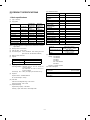
CONTENTS
[ 1 ] PRODUCT OUTLINE . . . . . . . . . . . . . . . . . . . . . . . . . . . . . . . . . . . . . . . . . . . . 1 – 1
[ 2 ] PRODUCT SPECIFICATIONS . . . . . . . . . . . . . . . . . . . . . . . . . . . . . . . . . . . . . 2 – 1
[ 3 ] PRODUCT VIEWS . . . . . . . . . . . . . . . . . . . . . . . . . . . . . . . . . . . . . . . . . . . . . . 3 – 1
[ 4 ] UNPACKING AND INSTALLATION . . . . . . . . . . . . . . . . . . . . . . . . . . . . . . . . . 4 – 1
[ 5 ] DESCRIPTION ON EACH SECTION . . . . . . . . . . . . . . . . . . . . . . . . . . . . . . . . 5 – 1
[ 6 ] DISASSEMBLY AND ASSEMBLY . . . . . . . . . . . . . . . . . . . . . . . . . . . . . . . . . . 6 – 1
[ 7 ] ADJUSTMENT . . . . . . . . . . . . . . . . . . . . . . . . . . . . . . . . . . . . . . . . . . . . . . . . . 7 – 1
[ 8 ] SIMULATIONS . . . . . . . . . . . . . . . . . . . . . . . . . . . . . . . . . . . . . . . . . . . . . . . . . 8 – 1
[ 9 ] SELF DIAGNOSTICS . . . . . . . . . . . . . . . . . . . . . . . . . . . . . . . . . . . . . . . . . . . . 9 – 1
[10] MEMORY TROUBLES, FLOWCHART FOR REPLACEMENT OF
MAIN CONTROL PWB . . . . . . . . . . . . . . . . . . . . . . . . . . . . . . . . . . . . . . . . . . 10 – 1
[11] MAINTENANCE . . . . . . . . . . . . . . . . . . . . . . . . . . . . . . . . . . . . . . . . . . . . . . . 11 – 1
[12] ELECTRICAL SECTION . . . . . . . . . . . . . . . . . . . . . . . . . . . . . . . . . . . . . . . . . 12 – 1
Parts marked with "!" is important for maintaining the safety of the set. Be sure to replace these parts with specified
ones for maintaining the safety and performance of the set.
SHARP CORPORATION
This document has been published to be used
for after sales service only.
The contents are subject to change without notice.
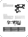
Contents
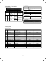
[1] PRODUCT OUTLINE . . . . . . . . . . . . . . . . . . . 1-1
1. Product features . . . . . . . . . . . . . . . . . . . . . . . . 1-1
[5] DESCRIPTIONS OF EACH SECTION
1.
2. System configuration (options) . . . . . . . . . . . . . 1-1
2) Basic operations . . . . . . . . . . . . . . . . . . . . 5-1
2.
2) Basic composition . . . . . . . . . . . . . . . . . . . 5-2
3. Supply parts . . . . . . . . . . . . . . . . . . . . . . . . . . . . 2-3
(1) Automatic document feeder (ADF) . . . . . . 2-5
3) Basic operations . . . . . . . . . . . . . . . . . . . . 5-3
3.
(4) Exclusive-use desk . . . . . . . . . . . . . . . . . . 2-6
Optical section . . . . . . . . . . . . . . . . . . . . . . . . . . 5-3
1) General description . . . . . . . . . . . . . . . . . 5-3
(2) 10-bin sorter . . . . . . . . . . . . . . . . . . . . . . . 2-5
(3) 10-bin staple sorter (10-bin SS) . . . . . . . . 2-6
Developing section . . . . . . . . . . . . . . . . . . . . . . 5-2
1) General descriptions . . . . . . . . . . . . . . . . . 5-2
2. Description of each section . . . . . . . . . . . . . . . . 2-2
4. Optional specifications . . . . . . . . . . . . . . . . . . . 2-5
Paper feed section . . . . . . . . . . . . . . . . . . . . . . 5-1
1) General descriptions . . . . . . . . . . . . . . . . . 5-1
[2] PRODUCT SPECIFICATIONS . . . . . . . . . . 2-1
1. Basic specifications . . . . . . . . . . . . . . . . . . . . . . 2-1
. . 5-1
2) Basic operations . . . . . . . . . . . . . . . . . . . . 5-6
4.
Copy process . . . . . . . . . . . . . . . . . . . . . . . . . . 5-8
1) Photoconductor . . . . . . . . . . . . . . . . . . . . 5-8
[3] PRODUCT VIEWS . . . . . . . . . . . . . . . . . . . . . . 3-1
2) Process diagram . . . . . . . . . . . . . . . . . . . . 5-9
1. External view and internal structure . . . . . . . . . 3-1
3) Details of image forming process . . . . . . 5-10
2. Operation panel . . . . . . . . . . . . . . . . . . . . . . . . . 3-2
4) Transition of photoconductor surface
potential . . . . . . . . . . . . . . . . . . . . . . . . . 5-14
3. Clutches, solenoids, and motors . . . . . . . . . . . . 3-3
5) Photoconductor drum sensitivity
correction . . . . . . . . . . . . . . . . . . . . . . . . 5-14
4. PWB . . . . . . . . . . . . . . . . . . . . . . . . . . . . . . . . . 3-4
5. Sensors and switches . . . . . . . . . . . . . . . . . . . . 3-5
6. Rollers, mirrors, etc. . . . . . . . . . . . . . . . . . . . . . 3-6
6) Process control function . . . . . . . . . . . . . 5-14
5.
TRANSPORT/FUSING SECTION . . . . . . . . . 5-16
[4] UNPACKING AND INSTALLATION . . . . . 4-1
1) General . . . . . . . . . . . . . . . . . . . . . . . . . . 5-16
1. Unpacking . . . . . . . . . . . . . . . . . . . . . . . . . . . . . 4-1
2) Basic composition and functions . . . . . . 5-16
. . . . . . . . . . . . . . . . . . . . . . . . . . . . 4-1
6.
Fusing paper exit section . . . . . . . . . . . . . . . . 5-16
(1)
Environment . . . . . . . . . . . . . . . . . . . . . . . 4-1
7.
High voltage section . . . . . . . . . . . . . . . . . . . . 5-17
(2)
Space around the machine . . . . . . . . . . . . 4-2
1) General . . . . . . . . . . . . . . . . . . . . . . . . . . 5-17
(3)
Installation base . . . . . . . . . . . . . . . . . . . . 4-2
2) Basic composition . . . . . . . . . . . . . . . . . . 5-17
(4)
Power source . . . . . . . . . . . . . . . . . . . . . . 4-2
[6] DISASSEMBLY AND ASSEMBLY . . . . . . 6-1
(5)
Grounding wire connection . . . . . . . . . . . . 4-2
2. Installation
3. Optical system lock release . . . . . . . . . . . . . . . . 4-3
A. No. 2/3 mirror unit lock release . . . . . . . . . 4-3
B. Lens and No. 4/5 mirror unit lock release . 4-3
4. Charger cleaning . . . . . . . . . . . . . . . . . . . . . . . . 4-3
A. Main charger unit electrode cleaning . . . . 4-3
5. Developing unit setting . . . . . . . . . . . . . . . . . . . 4-4
A. Developing unit setting . . . . . . . . . . . . . . . 4-4
6. Toner density sensor level adjustment . . . . . . . 4-5
A. Developing unit level adjustment . . . . . . . 4-5
7. Accessory installation . . . . . . . . . . . . . . . . . . . . 4-5
A. Copier tray installation . . . . . . . . . . . . . . . 4-5
8. Toner supply . . . . . . . . . . . . . . . . . . . . . . . . . . . 4-5
9. Center shift adjustment . . . . . . . . . . . . . . . . . . . 4-7
10. Label attachment . . . . . . . . . . . . . . . . . . . . . . . . 4-7
A. Label attachment . . . . . . . . . . . . . . . . . . . 4-7
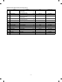
1. Paper feed unit . . . . . . . . . . . . . . . . . . . . . . . . . 6-1
1-1. Paper feed unit . . . . . . . . . . . . . . . . . . . . . 6-1
1-2. Paper feed roller ass’y removal . . . . . . . . 6-1
1-3. PS front roller ass’y . . . . . . . . . . . . . . . . . 6-2
1-4. Separation roller . . . . . . . . . . . . . . . . . . . . 6-2
1-5. Paper feed roller, take-up roller . . . . . . . . 6-2
2. Transport unit . . . . . . . . . . . . . . . . . . . . . . . . . . 6-3
2-1. Resist roller, transfer roller . . . . . . . . . . . . 6-3
2-2. Transport belt . . . . . . . . . . . . . . . . . . . . . . 6-4
3. Fusing section . . . . . . . . . . . . . . . . . . . . . . . . . 6-4
3-1. Fusing unit removal . . . . . . . . . . . . . . . . . 6-4
3-2. Heater lamp replacement . . . . . . . . . . . . . 6-5
3-3. Upper heat roller ass’y removal . . . . . . . . 6-5
3-4. Upper separation pawl replacement . . . . . 6-5
3-5. Lower heat roller replacement . . . . . . . . . 6-5
3-6. Lower separation pawl replacement . . . . . 6-6
3-7. Thermistor/thermostat removal . . . . . . . . . 6-6
4. Optical system . . . . . . . . . . . . . . . . . . . . . . . . . . 6-6
1) Copy lamp replacement . . . . . . . . . . . . . . 6-6
10-1. Separation roller . . . . . . . . . . . . . . . . . . . 6-24
2) Mirror base wire replacement and
adjustment . . . . . . . . . . . . . . . . . . . . . . . . 6-7
10-2. Take-up roller/paper feed roller . . . . . . . 6-24
3) No. 2/3 mirror unit (mirror base B)
installation (Mirror base B positioning) . . . 6-9
[7] ADJUSTMENTS . . . . . . . . . . . . . . . . . . . . . . . . 7-1
1. Developing section . . . . . . . . . . . . . . . . . . . . . . 7-1
4) Copy lamp unit installation
(Mirror base A positioning) . . . . . . . . . . . 6-10
1-1. Developing doctor clearance
adjustment . . . . . . . . . . . . . . . . . . . . . . . . 7-1
5) No. 4/5 mirror unit (mirror base C)
replacement . . . . . . . . . . . . . . . . . . . . . . 6-10
1-2. Developing magnet roller main pole
position adjustment . . . . . . . . . . . . . . . . . . 7-1
6) Lens wire replacement . . . . . . . . . . . . . . 6-12
2. Optical system . . . . . . . . . . . . . . . . . . . . . . . . . . 7-2
7) Lens unit replacement . . . . . . . . . . . . . . 6-15
2-1. Adjustment items . . . . . . . . . . . . . . . . . . . 7-2
5. High voltage section . . . . . . . . . . . . . . . . . . . . 6-15
2-2. Note for adjustments . . . . . . . . . . . . . . . . 7-3
5-1. Main charger (MC) unit . . . . . . . . . . . . . . 6-15
2-3. Adjustment of each section . . . . . . . . . . . 7-4
5-2. Transfer/separation charger (TC/SC)
unit . . . . . . . . . . . . . . . . . . . . . . . . . . . . . 6-16
A. Lens reference position adjustment . . . . . 7-4
6. Process section . . . . . . . . . . . . . . . . . . . . . . . 6-17
6-1. Process unit . . . . . . . . . . . . . . . . . . . . . . 6-17
6-2. Waste toner bottle replacement
(required when waste toner full detection/
maintenance) . . . . . . . . . . . . . . . . . . . . . 6-17
6-3. Drum (Replace every 60K copies) . . . . . 6-18
6-4. Blank lamp unit
(Clean every 60K copies.) . . . . . . . . . . . 6-18
6-5. Discharge lamp unit
(Clean every 60K copies.) . . . . . . . . . . . 6-19
6-6. Cleaner blade
(Replace every 60K copies.) . . . . . . . . . . 6-19
6-7. Drum separation pawl
(Replace every 60K copies.) . . . . . . . . . . 6-19
6-8. Process control PWB (Clean the sensor
section every 60K copies.) . . . . . . . . . . . 6-19
6-9. Drum mark sensor PWB (Clean the sensor
section every 60K copies.) . . . . . . . . . . . 6-19
B. No.4/5 mirror reference position
adjustment . . . . . . . . . . . . . . . . . . . . . . . . 7-4
C. Vertical copy magnification ratio
adjustment . . . . . . . . . . . . . . . . . . . . . . . . 7-5
D. Resolution adjustment
(Focus adjustment) . . . . . . . . . . . . . . . . . . 7-6
E. Horizontal copy magnification ratio
adjustment . . . . . . . . . . . . . . . . . . . . . . . . 7-8
F. Comparison table of lens values and
simulation input values . . . . . . . . . . . . . . . 7-9
G. Vertical skew adjsutment . . . . . . . . . . . . 7-10
H. Horizontal skew adjustment . . . . . . . . . . 7-10
I.
Center shift adjustment . . . . . . . . . . . . . . 7-12
J.
Exposure balance adjustment . . . . . . . . 7-12
K. Copy lead edge adjustment . . . . . . . . . . 7-13
2-4. Copy density adjustment . . . . . . . . . . . . 7-16
2-5. Process section adjustment . . . . . . . . . . 7-20
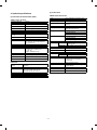
[8] SIMULATION
. . . . . . . . . . . . . . . . . . . . . . . . . . 8-1
6-10. Toner reception seal (Replace every 60K
copies.) . . . . . . . . . . . . . . . . . . . . . . . . . . 6-19
1. Outline . . . . . . . . . . . . . . . . . . . . . . . . . . . . . . . . 8-1
7. Developing section . . . . . . . . . . . . . . . . . . . . . 6-20
2. Purpose . . . . . . . . . . . . . . . . . . . . . . . . . . . . . . . 8-1
A. DV side seals F/R replacement
(Replace every 120K copies.) . . . . . . . . . 6-20
3. Operating procedure . . . . . . . . . . . . . . . . . . . . . 8-1
B. DB blade replacement
(Replace every 120K copies.) . . . . . . . . . 6-20
5. Details of simulations . . . . . . . . . . . . . . . . . . . . 8-3
C. V ring attachment . . . . . . . . . . . . . . . . . . 6-20
D. Note for toner hopper drive gear (31T)
and stirring shaft attachment . . . . . . . . . 6-21
8. Operation panel/intermediate cabinet . . . . . . . 6-21
9. Frame major parts . . . . . . . . . . . . . . . . . . . . . . 6-21
9-1. Cooling fan motor replacement . . . . . . . . 6-21
9-2. Power unit . . . . . . . . . . . . . . . . . . . . . . . . 6-22
9-3. Tray size detecting PWB . . . . . . . . . . . . 6-22
9-4. Main PWB unit . . . . . . . . . . . . . . . . . . . . 6-23
9-5. AC power PWB . . . . . . . . . . . . . . . . . . . . 6-23
9-6. Ozone filter (Check every 60K copies,
and clean every 300K copies.) . . . . . . . . 6-23
10. Multi paper feed unit . . . . . . . . . . . . . . . . . . . . 6-24
4. List of simulations . . . . . . . . . . . . . . . . . . . . . . . 8-2
6. User simulation
. . . . . . . . . . . . . . . . . . . . . . . 8-16
(1) Functions which can be set and
canceled by the user simulation . . . . . . . 8-16
(2) User simulation . . . . . . . . . . . . . . . . . . . 8-16
(3) User simulation code table . . . . . . . . . . . 8-17
(4) Department counter setting content
(Set with user program P10 ∼ P15) . . . . 8-17
[9] SELF DIAGNOSTICS . . . . . . . . . . . . . . . . . . . 9-1
1. Summary/purpose . . . . . . . . . . . . . . . . . . . . . . . 9-1
2. Operation . . . . . . . . . . . . . . . . . . . . . . . . . . . . . . 9-1
3. Clearing the self diag display . . . . . . . . . . . . . . 9-1
[10] SERVICING AT MEMORY TROUBLE
AND MAIN CONTROL PWB
REPLACEMENT . . . . . . . . . . . . . . . . . . . . . . . 10-1
1. General . . . . . . . . . . . . . . . . . . . . . . . . . . . . . . 10-1
2. Purpose . . . . . . . . . . . . . . . . . . . . . . . . . . . . . . 10-1
3. Remedies . . . . . . . . . . . . . . . . . . . . . . . . . . . . 10-1
4. Set value recording sheet . . . . . . . . . . . . . . . . 10-3
5. Memory simulation list . . . . . . . . . . . . . . . . . . . 10-4
[11] MAINTENANCE . . . . . . . . . . . . . . . . . . . . . . . 11-1
1. Maintenance cycle and maintenance items . . 11-1
[12] ELECTRICAL SECTION
. . . . . . . . . . . . . . 12-1
1. System block diagram . . . . . . . . . . . . . . . . . . . 12-1
2. Main circuit . . . . . . . . . . . . . . . . . . . . . . . . . . . 12-3
(1) Block diagram . . . . . . . . . . . . . . . . . . . . . 12-3
(2) CPU (IC6) SC3041K12F . . . . . . . . . . . . . 12-4
(3) Detector circuit of sensor signal . . . . . . . 12-8
(4) Start/stop control circuit . . . . . . . . . . . . . 12-8
(5) Heater lamp control circuit . . . . . . . . . . . 12-9
(6) Driver circuit (Solenoid, electromagnetic
clutch) . . . . . . . . . . . . . . . . . . . . . . . . . . 12-10
(7) Stepping motor drive circuit . . . . . . . . . 12-10
(8) AE (Auto Exposure) sensor circuit . . . . 12-11
(9) Toner supply motor drive circuit . . . . . . 12-11
(10) Reset IC (IC13) . . . . . . . . . . . . . . . . . . . 12-11
(11) Operation panel . . . . . . . . . . . . . . . . . . 12-12
(12) EnergyStar circuit description . . . . . . . . 12-13
[1] PRODUCT OUTLINE
1. Product features
(1)
•
•
Compact body
Compact body size
The body width of 600mm is the smallest in the class.
The employment of the front loading tray and the folding-type multi
manual paper feed cassette realizes the small occupying area.
(Option)
•
(2)
Clean copy gentle to the environment
Silent design,
•
Low level of ozone, use of recyclable materials
•
The energy-saving mode reduces the power consumption.
(3)
High capacity of copying
Warm-up time is less than 35 sec. The first copy of 5.3 sec.
•
(4)
Fully expandable system. (Refer to "2. System configuration.")
2. System configuration (options)
Automatic document feeder SF-A18
SF-MF15
(Option some areas)
Tray (reserve) SF-UB15
Exclusive-use desk
SF-DS17
10-bin sorter SF-S17 N
10-bin staple sorter SF-S54
Note: When installing the SF-S54, the exclusive-use desk (SF-DS17) is reguired.
1–1
[2] PRODUCT SPECIFICATIONS
(12) Additional functions
Function
Auto Paper Selection
×
1. Basic specifications
Auto Magnification ratio
Selection
×
(1)
Type: Table top
Shift
F
(2)
Copy speed:
1-set 2-copy
F
Edge erase
F
Built-in auditor
password mode
F
Interruption
F
Enlargement
Reduction
(Magnification) (Magnification)
Normal
A3
9 sheets/min
9 sheets/min
(200%)
9 sheets/min
(50%)
B4
11 sheets/min
11 sheets/min
11 sheets/min
Monochrom
×
A4 (Portrait)
16 sheets/min
13 sheets/min
13 sheets/min
AICS
F
A4 (Landscape)
13 sheets/min
13 sheets/min
13 sheets/min
Pre-heat mode
F
13 sheets/min
Auto shut off
F
13 sheets/min
Auto power save
F
Auto tray switching
×
11 sheets/min
Cover insertion
×
×
×
B5 (Portrait)
B5 (Landscape)
16 sheets/min
13 sheets/min
Ledger
Legal
13 sheets/min
13 sheets/min
9 sheets/min
11 sheets/min
9 sheets/min
11 sheets/min
9 sheets/min
16 sheets/min
13 sheets/min
13 sheets/min
OHP insertion paper
Letter (Landscape) 13 sheets/min
13 sheets/min
13 sheets/min
Overlay
Letter (Portrait)
(Note) The copy speeds for enlargement and reduction are minimum
speed values.
(4)
First copy time: 5.3 sec (Tray)
Occupying area (W x D)
(5)
Jam recovery time: 8 sec (Conditions: After leaving the door
open for 60 sec, the standard conditions)
Weight
(6)
Multi copy Max. 99 sheets
(7)
Original
885 × 595 mm
34-27/32″ × 23-7/16″
41.0Kg (90.4 lbs)
(14) Power source
Max. original size
Voltage: 100V 50/60Hz
110V 50/60Hz
120V 60Hz
127V 60Hz
220 ∼ 230V 50/60Hz
240V 50Hz
A3/Ledger
Left side/Center
Original sensing
No
Copy magnification ratio
Fixed magnification: AB series: 200, 141, 122, 115, 100, 86, 81,
70, 50% (9 steps)
Inch series: 200, 141, 129, 121, 100, 95, 77,
64, 50% (9 steps)
(9)
20 departments
600 × 595 × 365 mm
23-5/8″ × 23-7/16″ × 14-3/8″
WxDxH
Warm up time: 35 sec or less
(8)
Enlargement is impossible.
(13) External dimensions
(3)
Reference original size
Remark
Frequency: 50/60Hz common
(15) Power consumption
Max. power
consumption
1.5kw
Zoom range: 50% ∼ 200% (151 steps by the increment of 1%)
Energy efficiency
64Wh/h or less
Exposure
Auto power shut
off (for EPA)
5W or less
Exposure mode: Auto/Manual/Photo
No. of manual steps: 9 steps
(10) Void width
Void area: Lead edge/rear edge: 3mm or less
Image loss Normal: 4mm or less
(11) Paper exit/finishing
Paper exit tray capacity: 250 sheets
Finishing: option 10-bin sorter, 10-bin staple sorter
2–1
(Note) Max. when the
option is installed
(2)
2. Description of each section
(1)
Paper feed section
A3 ∼ A6/Ledger ∼ Invoice
Copying size
Paper feed system
Paper feed capacity
Cassette
Tray
Multi
manual
paper
feed
Multi
Paper size
250 sheets × 1
Paper weight
56 ∼ 80g/m2
Inch series:
Ledger ∼ Invoice
15 ∼ 21 lbs
AB series: A3 ∼
A6R
Single
Inch series:
Ledger ∼ Invoice
Light source
Halogen lamp
Exposure system
Slit exposure by moving the light source
Zooming system
By changing the lens positions and the scan
speed.
Lens
Fixed focus lens
1 tray + multi manual feed
AB series: A3 ∼
A5
AB series: A3 ∼
A6R
Inch series:
Ledger ∼ Invoice
Optical section
Paper kind
(3)
Standard paper,
recycled paper
2
56 ∼ 80g/m
15 ∼ 21 lbs
Standard paper,
specified paper,
special paper,
OHP film, Second
original paper,
postcards
(without folding)
52 ∼
128g/m2
14 ∼ 34 lbs
Process
Charging system
(–) DC saw teeth electrode system
Transfer system
(–) tungsten system
Separation system
(AC) separation tungsten system
(4)
Developing section
Developing system
Dry, two-component magnetic brush
development (developer replacement)
Developing bias voltage
DC–200V ±5V
(5)
Fusing section
Fusing system
Heat roller system
Upper heat roller surface temperature
190 degrees C
Halogen lamp 1000W × 1
Heater lamp
3. Supply parts
Middle East/Africa
Name
Life
Product name
Photoconductor drum
Cleaner blade
Drum separation pawl
x1
x1
x2
60K
SF-226DM
Black developer
Black developer (530g)
x 10
60K x 10
SF-226LD
Black toner
Black toner bottle (280g)
x 10
6K x 10
SF-126LT
4
Upper heat roller kit
Upper heat roller
Upper separation pawl
Fusing bearing
x1
x4
x1
120K
SF-216HU
5
Lower heat roller kit
Lower heat roller
Lower separation pawl
x1
x4
120K
SF-220LH
6
Staple cartridge
Staple cartridge (For SF-S54)
x3
5K staples x 3
SF-LS12
7
Upper heat roller
Upper heat roller
x1
120K
SF-216HU
8
Upper separation pawl
Upper separation pawl x 4
x 10
120K x 10
SF-216UP
1
Photoconductor kit
2
3
Content
9
Heat roller gear
Heat roller gear
x 10
120K x 10
SF-216HG
10
Lower heat roller
Lower heat roller
x1
120K
SF-216HR
11
Lower separation pawl
Lower separation pawl x 4
x 10
120K x 10
SF-216LP
12
Screen grid
Screen grid
x 10
120K x 10
SF-216SU
13
Cleaner blade
Cleaner blade
x 10
6K x 10
SF-216CB
14
Charging plate
Charging plate
x 10
120K x 10
SF-216PU
15
Ozone filter
Ozone filter
x 10
300K x 10
SF-216FL
16
Copy lamp
Copy lamp
x 10
—
SF-216CL
17
MC case unit
MC case unit
x 10
—
SF-216MC
2–2
Middle & South America/Asia (excluding China)
Name
Life
Product name
Photoconductor drum
Cleaner blade
Drum separation pawl
x1
x1
x2
60K
SF-226DR
Black developer
Black developer (530g)
x 10
60K x 10
SF-226CD
Black toner
Black toner bottle (280g)
x 10
6K x 10
SF-126CT
4
Upper heat roller kit
Upper heat roller
Upper separation pawl
Fusing bearing
x1
x4
x1
120K
SF-216HU
5
Lower heat roller kit
Lower heat roller
Lower separation pawl
x1
x4
120K
SF-220LH
6
Staple cartridge
Staple cartridge (For SF-S54)
x3
5K staples x 3
SF-LS12
7
Upper heat roller
Upper heat roller
x1
120K
SF-216HU
8
Upper separation pawl
Upper separation pawl x 4
x 10
120K x 10
SF-216UP
1
Photoconductor kit
2
3
Content
9
Heat roller gear
Heat roller gear
x 10
120K x 10
SF-216HG
10
Lower heat roller
Lower heat roller
x1
120K
SF-216HR
11
Lower separation pawl
Lower separation pawl x 4
x 10
120K x 10
SF-216LP
12
Screen grid
Screen grid
x 10
120K x 10
SF-216SU
13
Cleaner blade
Cleaner blade
x 10
6K x 10
SF-216CB
14
Charging plate
Charging plate
x 10
120K x 10
SF-216PU
15
Ozone filter
Ozone filter
x 10
300K x 10
SF-216FL
16
Copy lamp
Copy lamp
x 10
—
SF-216CL
17
MC case unit
MC case unit
x 10
—
SF-216MC
2–3
4. Optional specifications
(2) 10-bin sorter
(1) Automatic document feeder (ADF)
<Model name: SF-S17 N>
Type
Copier installation type/Hanging type
Distribution system
Bin shift by lead screw
No. of bins
10 bins (The top bin is used also for
non-sort.)
Capacity
30 sheets/bin (L4/letter size), 100
sheets for the top bin only.
Sorting
30 sheets (A4/letter)
<Model name: SF-A18>
Original set direction
Face up
Original set position
Center reference
Original transport system
Belt (half size) system
Original feed sequence
Bottom taking (Face up exit)
Original size
A3 ∼ A5/11" x 17" ∼ 8 1/2" x 5 1/2"
Original change speed
(S → S)
16 sheets/min
Original weight
50 ∼ 128g/m2 (14 to 34 lbs)
15 sheets (B4/legal)
15 sheets (A3/Ledger)
Grouping
20 sheets (A4/letter)
15 sheets (B4/legal)
15 sheets (A3/Ledger)
2
Original set quantity
50 sheets, 50 ~ 80 g/cm ,
80 ~ 128 g/m2 (21 to 34 lbs) thickness
max. 5 mm (3/16")
Original stop system
Position control system
Dimensions
571 (W) x 521 (D) x 110 (H) (mm)
22-31/64" (W) x 20-33/64" (D) x
4-11/32" (H)
(Height: excluding the tray)
Paper size
About 11.5kg (25.4 lbs.)
Power source
Supplied from the copier’s power section.
Power consumption
65W
A3 ∼ A6 (Postcard)R/11" x 17" ∼
8 1/2" x 5 1/2"
(Sort/group)
A3 ∼ A5/11" x 17" ∼ 8 1/2" x 5 1/2"
Paper transport
Center reference
Paper reception
Face up
Paper weight
Weight
(Non-sort)
(Non-sort)
52 ∼ 128g/m2 (14 ∼ 34lbs)
(Sort/group)
56 ∼ 80g/m2 (15 ∼ 21lbs)
Dimensions
335 (W) x 493 (D) x 298 (H) (mm)
13-13/64" (W) x 19-27/64" (D) x
11-47/64" (H)
(Width: Including the tray.)
Functions
Original sensing on
the tray
YES (Scanning read for uncertain size
originals.)
Weight
8.6kg [9.8kg (21.6 lbs.) Including
mounted fittings]
Sensing size
Inch series: 11" x 17", 8 1/2" x 14", 8 1/2" x
11", 8 1/2" x 11"R, 8 1/2" x 5 1/2"
AB series: A3, B4, A4, A4R, A5
Power source
Supplied from the copier. DC24V (1.2A)
Power consumption
Max. 30W
Original mixture
Allowed (However, no linkage with the AMS)
Original reverse
NO
2–4
(3) 10-bin staple sorter (10-bin SS)
Staple section
<Model name: SF-S54>
Type
Copier stapler
Type
Copier installation type/hanging type
Stapling time
1.8 sec
Distribution system
Bin shift system by lead screw
No. of stapled sheets
30 sheets (80g/m2, 21 lbs.)
No. of bins
10 bins (The top bin is commonly used
for non-sort.
Binding reference
Front reference
Staple supply
Cartridge (5,000 pcs.)
Staple
SF-LS12
No staple/no cartridge/
no stapler detection
Available
Capacity
30 sheets for each bin
(A4, 8 1/2" × 11", 80g/m2)
100 sheets for the top bin
30 sheets (A4, 8 1/2" × 11")
Sort
15 sheets (B4, 8 1/2" × 14", 8 1/2" × 13")
Staple jam detection
Available
15 sheets (A3, 11" × 17")
80g/m2 (21 lbs.)
Manual staple mode
Available (excluding manual stapling)
20 sheets (A4, 8 1/2" × 11")
Grouping
15 sheets (B4, 8 1/2" × 14")
15 sheets (A3, 11" × 17"),
80g/m2 (21 lbs.)
30 sheets (A4, 8 1/2" × 11")
Staple sort
Paper size
(4) Exclusive-use desk
SF-DS17
570(W) × 523(D) × 520(H)mm
15 SHEETS (B4, 8 1/2" × 14")
Dimensions
15 sheets (A3, 11" × 17")
80g/m2 (21 lbs.)
Weight
About 19.5kg
Functions
Caster
Provided
Adjuster
None
Door
None
Non-sort
A3 ∼ A6R
11" × 17" ∼ 8 1/2" × 5 1/2"
Sort/group
A3 ∼ A5
11" × 17" ∼ 8 1/2" × 5 1/2"
Staple sort
A3, B4, A4, A4R, B5, 11 × 17",
8 1/2 × 14", 8 1/2 × 11", 8 1/2 × 11R
Alignment (Sorting)
Max. shift 2mm (Alignment operation)
Paper transport
Center reference
Paper loading
Face up
Paper weight
Note: When installing the SF-S54, the exclusive-use desk (SF-DS17,
SF-DS17E) is required.
Non-sort
49 ∼ 128g/m2 (13 ∼ 34 lbs.)
Sort/group/staple sort
56 ∼ 80g/m2 (15 ∼ 21 lbs.)
Dimensions
390(W) × 542(D) × 400(H)mm
15-23/64" (W) × 21-11/32" (D) ×
15-3/4" (H)
Weight
About 11.5kg, 15kg (33.1 lbs.) [including
the installation kit]
Power source
DC24V (1.5A) supplied from the copier.
Power consumption
Max. 36W
2–5
[3] PRODUCT VIEWS
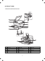
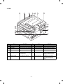
1. External view and internal structure
5
6
1
4
2
7
8
9
3
10
4
11
12
14
15
16
13
No.
Name
No.
Name
No.
Name
1
Original cover
2
Original table
3
Paper exit tray
4
Grip
5
Manual feed original guide
6
Manual feed tray
7
Operation panel
8
Front cover
9
Power switch
F
Paper tray
G
Developing unit grip
H
Toner hopper
I
Fusing unit
J
Developing unit lock lever
K
Release lever
L
Drum
3–1
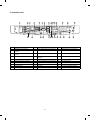
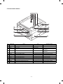
2. Operation panel
1
2
3
SORTER
4
5
EXPOSURE
DUAL PAGE
COPY
SORT
MARGIN
SHIFT
1 2 3
8
81/2 x 51/2 11x 17
4 5
16
No.
DARK
129%
81/ 2 x 14 11x17
121%
1
100%
81/2 x14
81/2 x11
81/2 x11
81/2 x 51/2
81/2 x 51/2
18
77%
ZOOM
64%
50%
INTERRUPT
15
POWER SAVE
2
AUDIT CLEAR
3
4
5
6
7
8
9
CA
%
0/
19
14
95%
TRAY SELECT
17
Name
13
200%
81/2 x 11 11x 17
81/2 x 51/2 81/2 x11
11 x17
81/2 x14
11 x17
81/2 x11
11 x17
EDGE ERASE
LIGHT
9 10 11 12
141%
11 x 17
8 1/ 2 x 14
8 1/ 2 x 11
8 1/ 2 x 5 1/ 2
8 1/ 2 x 11 R
EXTRA
PHOTO
STAPLE
SORT
7
PAPER SIZE
AUTO
MANUAL
GROUP
6
20 21 22 23
24
25
C
26
27
28
No.
Name
No.
1
SORTER key and indicators
2
DUAL PAGE COPY key and indicator
3
MARGIN SHIFT key and indicator
4
AUTO/MANUAL/PHOTO key and
indicators
5
PAPER SIZE indicators
6
Misfeed indicator
7
Paper feed location/misfeed location
indicators
8
Preset ratio indicators
9
Copy quantity display
F
Maintenance required indicator
G
Developer replacement required
indicator
H
Toner required indicator
I
10-key pad
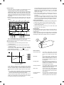
J
POWER SAVE indicator
K
AUDIT CLEAR key
L
EDGE ERASE key and indicator
M
LIGHT and DARK keys and indicators
N
TRAY SELECT key
O
Paper required indicator
P
Copy ratio selector keys
Q
ZOOM indicator
R
Copy ratio display key
S
Zoom keys
T
INTERRUPT key and indicator
U
Zero/readout key
V
Clear key
W
Print button and READY indicator
X
Clear all key
3–2
Name
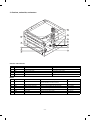
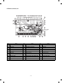
3. Clutches, solenoids, and motors
6
8
9
7
1
11
12
2
3
5
10
4
Clutches and solenoids
No.
Signal name
Name
Functions, operations
1
PSPS
Paper separation solenoid
Paper separation solenoid drive
2
RRC
Resist roller clutch
For resist roller rotation
3
TRC
Transport roller clutch
For transport roller rotation
4
CPFC1
Tray paper feed clutch
For paper feed roller rotation
5
MPFS
Manual paper feed solenoid
For pressing take-up roller
Motors
No.
Signal name
Name
Functions, operations
Type
6
VFM
Ventilation fan motor
Used to ventilate around the fusing section, cools
down the machine, and remove ozone.
DC brushless
7
MM
Main motor
Used to drive the body.
DC brush
8
CFM
Optical system cooling fan
Used to cool and ventilate the optical system.
DC brushless
9
LM
Lens motor
Used to move the optical lens.
DC stepping
F
TM
Toner motor
Used to stir toner.
DC synchronous
G
MRM
Mirror motor
Used to move the mirror base.
DC stepping
H
SMF
Suction fan motor
Used to ventilate the suction section.
DC brushless
3–3
4. PWB
15
1
2
3
4
5
14
16
7
6
11
8
13
12
9
10
No
1
Name
Description
No
Name
Description
Operation PWB A
Operation input, display control
2
Operation PWB B
Operation input, display control
3
Blank lamp PWB
Used to control the blank lamp.
4
DL PWB
Used to drive the discharge lamp.
5
Optical PWB
AE sensor and lens motor interface
6
Process control PWB
Used to sense the toner density.
7
Main PWB
Used to control the body.
8
AC circuit PWB
AC power input
9
CSD PWB
Used to sense the body cassette
size.
F
DC circuit PWB
DC power input
G
PID PWB
Manual paper entry detection
H
PPD PWB
Body PR roller JAM detection
I
High voltage PWB
Process high voltage, developing
bias voltage supply
J
POD PWB
Body paper exit section JAM
detection, ventilation fan motor
interface
K
Mark sensor PWB
Drum marking point detection
L
Sub DC power PWB
Supplies power in the energy
saving mode. (Supplies 5V to the
main PWB and the operation
PWB.)
3–4
5. Sensors and switches
2
3
5
4
6
7
1
10
14
8
9
11
13
12
No.
Signal name
Name
Type
Operation, function
1
TCS
2
ILSW
3
MSW
4
TH
Fusing heater thermistor
Thermistor
Greater resistance at low
temperature
5
TS
Fusing heater thermostat
Thermostat
Contact open at abnormally high
temperature
6
POD
Paper exit paper sensor
Transmission photo sensor
LOW when paper is present.
7
MHPS
Mirror home position sensor
Transmission photo sensor
HIGH when paper is sensed.
8
MMRE
Main motor encoder
Transmission photo sensor
Rotation pulse output
9
TFD
Waste toner full switch
Lead switch
HIGH when sensed.
F
LHPS
Lens home position sensor
Transmission photo sensor
LOW when reduction.
G
PPD
Paper transport sensor
Transmission photo sensor
LOW when paper is present.
H
PED1
Body upper tray paper presence detection
Transmission photo sensor
HIGH when paper is present.
I
DPPD1
Body upper tray paper transport sensor
Transmission photo sensor
LOW when paper is present.
J
PID
Single manual feed paper entry sensor
Transmission photo sensor
HIGH when paper is present.
Toner density control sensor
Transmission sensor
HIGH when toner density falls.
Front cabinet open/close switch
Interlock switch
ON when closed.
Power switch
Seesaw switch
3–5
6. Rollers, mirrors, etc.
30 29
28 20
19 18
3
4
17
7
34
16
6
5
8
14
15
12
2
13
1
11
9
32
33
38
35
31
No.
Name
27
26
25
24
No.
23 22 21
Name
37
36
No.
Name
1
No. 3 mirror
2
No. 2 mirror
3
No. 1 mirror
4
Copy lamp
5
No. 4 mirror
6
No. 5 mirror
7
No. 6 mirror
8
Developing unit toner box
9
Manual tray
F
—
G
Take-up roller
H
Paper feed roller
I
Reverse roller
J
PS front roller follower roll
K
PS front roller
L
Developing unit
M
Blank lamp
N
Main charger unit
O
Photoconductor drum
P
Cleaner unit
Q
Resist roller follower roll
R
Resist roller
S
Transfer charger
T
Separation charger
U
Drum separation pawl
V
Suction unit
W
Suction belt
X
Fusing thermistor
Y
Heater lamp
Z
Upper heat roller
[
Lower heat roller
\
Transport roller (upper) follower roller
]
Transport roller (upper)
^
Developing magnet roller
_
Tray paper feed roller
‘
Tray paper feed reverse roller
a
Tray paper feed take-up roller
b
PE actuator
3–6
2 Avoid high temperature and high humidity, and avoid sudden
[4] UNPACKING AND INSTALLATION
temperature change. (Avoid installation near a cooler or a heater.)
If not, paper absorbs moisture and dew forms in the machine,
causing paper jam or degraded image quality.
1. Unpacking
(Standard condition):
20 ∼ 25°C:
(Temperature and humidity):
The best condition to use the machine.
65±5%RH
15 ∼ 30°C
20% ∼ 85% RH
35°C for 65%
% HR
85
65
Humidity
20
15
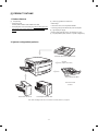
Packing material/accessory list
Name
Q’ty
1
Paper exit tray
1
2
Instruction manual
1
3
Maintenance card
1
4
Dust cover
1
5
Service contract
1
6
Installation manual
1
7
Magnification ratio select label
1
30
35 ˚C
3 Avoid dust and vibrations.
If dust enters the machine, malfunctions may occur.
2. Installation
Installing conditions
The surrounding conditions of the machine affect the machine performance greatly. Use great care for the following items.
4 Avoid installation on an unstable surface.
Keep the machine in level state to maintain the performance.
(1) Environment
1 Avoid direct sunlight, and avoid installation near the window. (Curtains or blinds must be shut completely.)
If not, the plastic parts and the original cover may be deformed.
Even if the window is of frosted glass, there is no difference.
4–1
5 Avoid installation to a poorly ventilated place.
(5) Grounding wire connection
1 Connect the grounding wire to prevent against a danger.
2 When connecting the grounding wire, connect only to the grounding object (the grounding terminal of the power outlet, etc.) and
never connect to a gas pipe.
6 Avoid installation to a place where there are flammable materials
or ammonia gas, etc. If the machine is installed near a diazo
copier, the picture quality may be degraded and malfunctions may
occur.
7 Install near a power outlet.
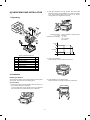
(2) Space around the machine
Install the machine with its rear side about 10cm (6 inches) apart from
the wall in order to allow space to ventilation by the cooling fan.
Also allow enough space around the machine for proper operation.
(3) Installation base
Set the machine in horizontal position in the following procedure.
Be sure to use a leveling instrument (UKOGM0054CSZZ) to install
the machine on a flat, horizontal place.
(Note) If the machine is not in horizontal position, the toner density
control function may not work normally, resulting in degraded
picture quality.
(4) Power source
1 Use the power source of the rated capacity.
2 Avoid complicated wiring. If not, the breaker or the fuse may be
overloaded.
4–2
3. Optical system lock release
4. Charger cleaning
A. No. 2/3 mirror unit lock release
A. Main charger unit electrode cleaning
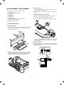
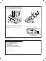
Remove the one fixing screw of the No. 2/3 mirror unit on the left side
of the copier.
1 Press the hook section of the main charger unit to release lock,
and pull out and remove the main charger unit from the copier.
Hook
Mirror unit
fixing screw
main charger unit
2 Remove one fixing screw of the main charger unit (on the back
side).
Fixing screw
Electrode section
B. Lens and No. 4/5 mirror unit lock release
Remove two fixing screws of the No. 4/5 mirror unit on the right inside
of the copier.
Open the front cabinet and remove one fixing screw of the lens on the
lower side of the operation panel.
Main charger unit
3 Press the electrode cleaner onto the tips of the electrode so that
the tips are inserted into the cleaner a few times to clean.
(Note)
Mirror unit
fixing screw
Lens fixing screw
•
Do not move the cleaner back and forth with the electrode tips
inserted into it.
•
When cleaning, clean thoroughly at one time. Avoid partial
cleaning.
Paper feed tray
Electrode cleaner
Electrode section
4 Return the electrode section to the original position and fix it with a
screw.
4–3
5 Insert the main charger unit along the guide groove in the copier
3 Remove three fixing screws of the toner hopper of the developing
fully to the bottom.
unit, and remove the toner hopper.
Fixing screw
Fixing screw
Toner hopper
Main charger unit
Developing unit
5. Developing unit setting
4 While supplying developer from the developer supply port of the
developing unit, turn the MG gear clockwise with a screwdriver or
a scale to supply fully in the developing unit.
A. Developing unit setting
1 Open the front cabinet, remove the installation toner fixed to the
developing unit level with tape, and pull the developing unit lever
toward you.
Developer
2 Hold the grip of the developing unit, and slowly pull out the
Developer
supply port
developing unit until it stops.
Then hold the hand carry strap and press the developing lever,
and remove the developing unit.
Hand carry strap
Developing unit
MG gear
Screwdriver (+) or scale
5 Install the toner hopper to the developing unit and fix it with two
screws.
DV lever
Developing unit
Grip
Fixing screw
Toner hopper
Fixing screw
Developing unit
4–4
6 Hold the hand carry strap of the developing unit and insert it into
7. Accessory installation
the copier fully to the bottom.
A. Copier tray installation
Install the copy tray to the paper exit section on the left side of the
copier.
Hand carry strap
Copy tray
Developing unit
Grip
7 Close the developing unit lever and close the front cabinet.
8. Toner supply
1 Open the front cover.
Developing unit lever
Front cabinet
2 Pull down the developer unit lock lever and pull the developer unit
out slowly unit it stops.
With the above procedure, setting of the developing unit is completed.
6. Toner density sensor level adjustment
Turn on the copier power switch.
A. Developing unit level adjustment
1 Execute simulation 25.
0
C
5
2
2
2 After 3 minutes, simulation 25 is completed.
(Note) If the simulation is terminated halfway, automatic reading
is not performed. Do not terminate it halfway.
3 Cancel simulation 25 with the CA key.
4–5
3 Hold the new toner bottle as shown and shake it four or five times.
6 Close the toner hopper cover.
4 Open the toner hopper cover.
7 Slide the developer unit into the copier.
8 Return the developer unit lock lever into place.
5 Pour the toner evenly into the toner hopper.
9 Close the front cover.
4–6
9. Center shift adjustment
10. Label attachment
There is basically no need to perform the center shift adjustment
because it is made when shipping. If the center should be shifted,
adjust in the following procedures.
Make a copy. If the center is shifted as shown in Fig. 1 or Fig. 2,
loosen the four screws which are fixing the cassette grip cabinet.
Section b
A. Label attachment
Attach the magnification ratio select label packed together with the
Operation manual to the position shown in the figure below.
•
Magnification ratio select lable
Section b
Section a
Direction A
When attaching the label to the copier with the original cover.
Section a
Direction B
(Note) When fixing the cassette cabinet, the fixing screws and the
cabinet clearance a and b are in symmetry.
[Reference figure]
Section b
Section a
•
When attaching the label to the optional automatic original feeder
(SF-A18)
Magnification ratio select lable
(1) Fig. 1
Move the cassette grip cabinet in direction A, tighten two fixing
screws (a) and tow fixing screws (b) in this sequence. Make a copy
again and check the center.
Paper center line
[Fig.1]
Image center line (First image)
(2) Fig. 2
Move the cassette grip cabinet in direction B, tighten two fixing
screws (a) and tow fixing screws (b) in this sequence. Make a copy
again and check the center.
[Fig.2]
Paper center line
Image center line (First image)
4–7
2) Basic operations
[5] DESCRIPTIONS OF EACH
SECTION
(Tray paper feed operation)
When the CPFC (Cassette paper feed clutch) turn on, the paper feed
roller shaft, the paper feed roller, and the take-up roller rotate in the
direction of A. At the same time, the limiter spring moves down the
roller release arm. As a result, the take-up roller falls by its own
weight onto the paper surface, starting paper feed.
Descriptions are made on the following sections:
1 Paper feed section
2 Developing section
Roller release arm
3 Optical section
Take-up
roller
4 Process section
5 Separation/transport section
6 Fusing/paper exit section
7 High voltage section
Paper feed roller
Paper feed roller shaft
3
4
6
When the CPFC turns off, rotation stops and the take-up roller is
pushed up to the original position by the roller release arm spring.
2
1
5
1. Paper feed section
(Manual paper feed operation)
There is no special mechanism for manual paper feed other than the
manual feed paper sensing actuator and the paper guide.
When the CPFC turns off, rotation stops and the take-up roller is
pushed up to the original position.
1) General descriptions
To realize the compact design, the front loading system and the foldable multi paper feed unit (Option for some areas) are employed.
50
Sheets
250 sheets
The paper feed tray is of the universal type and has capacity of 250
sheets. The front loading system allows the tray to be loaded from the
lower side of the front cabinet.
Manual paper feed is made in the multi paper feed.
5–1
2. Developing section
(Details of DV harness connector)
1) General descriptions
For bias
(1) Two-component developer
The developer is composed of toner and carrier.
Carrier serves as a medium for attaching toner onto the electrostatic
image on the photoconductor drum.
By stirring toner and carrier, they are rubbed to be charged positive
(+) and negative (–) respectively.
Since developer will deteriorate to degrade copy quality, it should be
replaced regularly.
GND
GND
(2) Two-component magnetic brush development
*For toner density sensor
The rotatable non-magnetic sleeve is provided over the magnet roller
and is rotated.
Carrier forms a magnetic brush on the sleeve surface by magnetic
force to attach toner onto the electrostatic image on the photoconductor drum.
VB
*Resistance value is identified by color
(3) Developing bias
When the photoconductor is charged and exposed to light (exposure), the surface potential (voltage) of the photoconductor will not
be lost completely. (The residual potential remains.)
Toner is attracted to the photoconductor by this residual potential,
dirtying the photoconductor. As a result, a dirty copy of white background is generated.
To prevent against this, a voltage of the same polarity and higher than
the residual potential is applied to the MG roller, preventing toner from
being attached to the photoconductor surface.
2) Basic composition
2
Residual potential < DV BIAS
4
1
MG roller
3
5
DV BIAS
-200V
Toner
Carrier
No.
Developing bias voltage
(4) DV harness
The toner density sensor, the developing bias, harness.
(For details, refer to [6] DISASSEMBLY AND ASSEMBLY.)
(Viewed from the rear of develoing unit)
DV harness connector
5–2
Name
1 Magnet roller
Forms a magnetic brush of carrier
by magnetic force.
2 Developing doctor blade
Limits the height of the magnetic
brush.
3 Developing MIX roller
Stirs carrier in the developing unit
and distributes toner evenly.
4 Toner transport roller
Transport toner sent from the
toner hopper unit to the stirring
section.
5 Toner density sensor
Senses
toner
developer.
density
in
3) Basic operations
(Cassette paper feed)
When the CPFC (cassette paper feed clutch) is turned on, the paper
feed roller shaft, the paper feed roller, and the take-up roller rotates in
the direction of A, and the roller release arm is moved downward by
the limiter spring. As a result, the take-up roller falls by its weight to
reach the paper surface, feeding the paper. When the CPFC is turned
off, the take-up roller is pushed up to the position by the roller release
arm spring.
Proccess
unit
Main motor
Main drive unit
Stirring roller
DV drive unit
Fuser unit
MG roller
Cleaner
unit
Transport
unit
PS roller
Paper exit
roller
Multi manual
insertion paper
feed unit
(Option)
Transport
roller(upper)
Transport
roller(lower)
Paper feed
rive unit
Paper feed
unit
Paper feed
unit
3. Optical section
1) General description
• The optical section of this
model is composed of the fixed focus
lens and six mirrors. Since the fixed focus lens is used, No. 4/5
mirror base is shifted according to the shift of the lens to change
the distance between the original and the drum (OID, Original
Image Distance) in reduction or enlargement copy.
The lens and No. 4/5 mirror unit are shifted by driving the stepping
motor with the signals from the main control PWB, allowing zooming of 151 steps in 1% increment in the range of 0.50 to 2.00.
16
10
4
11
5
1
6
•
Exposure is adjusted by changing the copy lamp voltage. The AE
sensor is provided in the zoom base to sense the density of the
original.
The copy lamp light is reflected by the original to the AE sensor,
which senses the density of the original and adjust the copy lamp
light quantity according to the density.
•
The exposure system is the slit exposure system by moving light
source.
2
3
17 15
7
14
8
13
9
12
1
Copy lamp
2
Reflector
3
No. 1 mirror
4
No. 2 mirror
5
No. 3 mirror
6
Lens
7
No. 4 mirror
8
No. 5 mirror
9
No. 6 mirror
F
No. 2/3 mirror base unit
G
Copy lamp unit
H
No. 4/5 mirror base unit
I
Mirror motor
J
Lens/No. 4/5 mirror base drive motor
K
Lens home position sensor
L
Mirror home position sensor
M
Automatic exposure (AE) sensor/
Optical system dirt sensor
5–3
(1) Original table
(2) Copy lamp
The original table is fixed. The original is set in the left center position.
100V series: 85V, 275W
200V series: 170V, 310W
(3) Mirror
This model uses six mirrors.
No. 1 mirror is attached to the copy lamp unit, No. 2/3 mirrors are
attached to No. 2/3 mirror base, No. 4/5 mirrors are attached to No.
4/5 mirror base.
The copy lamp unit and the No. 2/3 mirror base unit are scanned in
copying. The No. 4/5 mirror base is shifted in zoom copying to
change the distance between ten original and the drum.
(4) Lens (fixed focus lens)
•
•
•
Construction (1 group 3 lenses)
Brightness (F8.5)
Focus: (195mm ±1%)
(5) Lens home position sensor (LHPS)
This sensor senses the lens home position. The output signal of this
sensor is the basic signal to control the copy magnification ratio.
(6) Lens base
The lens is mounted to the lens base, which is shifted toward the
paper feed direction in reduction copy or toward the paper exit direction in enlargement copy by the lens drive motor.
Mirror base scan speed is changed for zooming
Enlargment
Normal
Zooming by changing the lens
and mirror position
Original
Reduction
Copy direction
5–4
Parts identification and functions
Lens home position sensor
Mirror home position sensor
No. 2/3 mirror unit
AE sensor
Reflector
Copy lamp unit
Lens No. 4/5 mirror unit
drive motor N
Mirror motor
Copy lamp
Lens drive wire
No. 4/5 mirror unit
Lens
Lens
unit
Mirror base wire
Temperature fuse
(7) Lens drive shaft
(14) Temperature fuse
This shaft controls the optical axis of the lens in zoom copy. The lens
follows along the slide base shaft.
This is to shift the lens unit and the No. 4/5 mirror base.
This is attached closely to the reflector to prevent against abnormal
temperature rise in the optical system. If the temperature rises abnormally, it turns off the copy lamp power directly.
100V series (117°C)
200V series (117°C)
(9) No. 4/5 mirror unit
(15) Reflector
No. 4/5 mirrors are attached to this unit. It is shifted by the lens drive
motor to change the distance between the original and the drum
according to the zooming ratio.
Light from the copy lamp is reflected by the reflector to the original.
(10) Mirror motor
Four exposure adjustment plates are attached to the copy lamp unit
to adjust exposure balance in back and forth direction of the frame.
(8) Lens drive wire
(16) Exposure adjustment plate
This stepping motor shifts the copy lamp unit and the No. 2/3 mirror
base. It is rotated at the rpm according to each zooming ratio.
(17) Mirror base drive wire
This wire transmits the mirror motor power to the copy lamp unit and
the No. 2/3 mirror base to scan the mirror base.
(11) Mirror home position sensor (MHPS)
This sensor senses the home position of the copy lamp unit. It is of
light transmission type.
(18) Lens drive motor
(12) No. 2/3 mirror unit
This stepping motor drives the lens and the No. 4/5 mirror base.
No. 2/3 mirrors are attached to this unit. It is scanned by the mirror
motor.
(19) AE sensor
This AE sensor senses the original density by the light emitted from
the copy lamp and reflected by the original, controlling the developing
bias. The photometric area is about 100m width at the center and in
the mirror base scanning direction.
The element is photo diodes.
(13) Copy lamp unit
This is composed of No. 1 mirror, the temperature fuse, the copy
lamp, the exposure adjustment plate, and the reflector, and scanned
by the mirror motor.
5–5
2) Basic operations
Mirror base scan speed
(Positions of the original, the lens, and the image in each magnification ratio)
Lens and mirror positions
are changed to adjust the
magnification ratio
Normal: The distance between the original set on the table glass and
the lens is equal to the distance between the lens and the
drum, resulting in the equal size of the original and the
image.
Copy paper
feed derection
Mirror scan speed is cahnged to adjust the magnification ratio
Mirror scan speed Drum rotation speed<Mirror scan speed
Enlargement
Enlargement: Compared to the normal copy, the lens is nearer to the
original and the distance between the original and the
lens is shorter.
The distance between the No. 4/5 mirror unit and the
lens is greater, and the distance between the lens and
the drum is also greater.
The distance between the original and the exposure
surface of the drum is greater than that in the normal
copy.
Original
Reduction
(Copy lamp control in each copy density)
[MAX. 83V(166V)]
80
70
CLV
60
(Copy lamp
application 50
voltage)
Reduction: Compared to the normal copy, the lens is nearer to the
drum, and the distance between the original surface and
the lens is longer.
The distance between the lens and the exposure surface
of the drum is shorter.
The distance between the No. 4/5 mirror unit and the
lens is greater.
The distance between the original and the exposure surface of the drum is greater than that in the normal copy.
40
[MIN. 45V(90V)]
(V)
EX1
2
3
4
EX5
Execute Sim 46-01 to determine the copy lamp application voltage
(CLV) in EX1 and EX5.
Then divide the difference between the voltages of EX1.0 and EX5.0
into nine.
The application voltage of the copy lamp in each exposure level is
determined by varying the ON timer duty of the copy lamp ON control
signal.
•
5–6
Photo density copy mode
Make the same control procedures as the manual density copy
mode.
The image density is controlled by lowering the grid bias voltage of
the charging charger. To maintain the reproduction quality in half
tone, the ON time duty of the copy lamp ON signal is made shorter
than in the manual density copy mode. (The application voltage is
lower.)
(Optical system dirt correction)
This model perform dirt correction by changing the copy lamp intensity according to the dirt degree in the optical system (the copy lamp
unit, No. 1 mirror, No.2 mirror, No.3 mirror) to prevent against remarkable degrading of copy quality.
The reference value is the AE sensor output value which is obtained
when the reference plate is exposed with the copy lamp voltage of
67.0V (134.0V) at power ON.
This value is checked with sim 44-08, 09.
Reference plate (Glass holder)
Table glass
Copy lamp light quantity "UP"
Automatic exposure
sensor
CPU
Reference value
>Measured value
Correction data output
CLV
Sim46
100
200
300
400
79.8K
80K
CLV + (0.7)
(1) Setting the reference value for optical system correction.
(2) Dirt correction
Reference plate (Glass holder)
Reference plate (Glass holder)
Table glass
Table glass
Copy lamp light quantity "UP"
Automatic exposure
sensor
Automatic exposure
sensor
CPU
Reference value
>Measured value
Correction data output
CPU reference value
setting
1 Clean the optical system at every maintenance.
1 Measure light quantity when performing mirror initialization.
2 Perform Simulation 46-1.
(The previous data are cleared.)
2 Store the correction data into memory.
3 Reset the register inside the CPU.
3 After completion of Simulation 46-1, when performing the first
mirror initialization, measure light quantity of the copy lamp.
Obtain the average value from the four measurement values and
use the average value as the reference value for correction.
1234
800ms
CL
Light quantity
measurement
Obtain the average value of four AE sensor values, and store it.
5–7
4. Copy process
This model basic process and structure
• The Scorotron method is used to evenly charge the photoconductor surface to the given potential in the charge process. The
corona wire regularly used is now replaced with a new corona
charge mechanism that employs the 0.1mm thick stainless steel
saw teeth plate, in order to suppress ozone generated when the
oxide molecule in air is ionized.
•
Considering the service efficiency, the process separation
mechanism is adopted.
•
To prevent high voltage leakage by the loose corona charge unit, a
one-touch stopper mechanism is adopted.
Proccess
unit
Main motor
Main drive unit
Stirring roller
DV drive unit
Fuser unit
MG roller
Cleaner
unit
Transport
unit
PS roller
Paper exit
roller
Multi manual
insertion paper
feed unit
(Option)
Transport
roller(upper)
Transport
roller(lower)
Paper feed
unit
Paper feed
rive unit
Paper feed
unit
1) Photoconductor
• This model uses OPC
(organic photoconductor) as photoconduc-
tive material. (φ50 mm)
OPC layer
CTL (Electric charge moving layer)
CGL (Electric charge generating layer)
Aluminum layer
5–8
2) Process diagram
Original
Mirror lens
Copy lamp
High voltage unit
Charging
Main corona unit
Discharge
Discharging
Discharge lamp
Blank lamp
Exposure
High voltage unit
Toner
Development
Cleaning blade
Waste toner collection
Paper exit
Developer
Cleaning
Separation
Fusing
Manual paper feed
Drum upper
image/paper
synchronization
Separation
Resist roller
Paper feed roller
Transportroller
Paper cassette
Transfer
Heat roller
Separation corona unit
Heater lamp
High voltage unit
Transfer charger
Image forming process
Paper transport path
High voltage unit
1 Main corona unit
2
1
2 Blank lamp
3
9
3 Developer unit
4 MG roller
8
4
5 Transfer corona unit
6 Separation corona unit
7 Separation pawl
8 Cleaning blade
7
9 Discharge lamp
6
5
5–9
3) Details of image forming process
Step 1 (Main Charging)
By negative discharging of the main charger, uniform negative charges are applied to the OPC drum surface.
The OPC drum surface potential is controlled by the screen grid
voltage to maintain the grid voltage at a constant level.
•
When the drum surface potential is lower than the grid voltage,
electric charges generated by discharging of the charger go
through the screen grid to charge the drum surface potential until it
becomes equal to the grid voltage.
•
When the drum surface potential virtually reaches the grid potential
level, electric charges generated by discharging of the charger
flows through the electrode of the screen grid to the high voltage
unit grid voltage output circuit, thus always maintaining the drum
surface potential at a level virtually equal to the grid voltage.
•
1 Main corona unit
2 Blank lamp
3 Developer unit
4 MG roller
The main corona unit employs the scorotron system to charge the
photoconductor surface to a certain level uniformly.
In addition, the conventional corona wire is replaced with the
corona charging mechanism by saw-teeth plate (stainless steel
plate of 0.1 mm thick). In corona discharge, oxygen molecules in
the air are ionized to generate ozone (O3). The mechanism restrict
the generation of ozone.
5 Transfer corona unit
6 Separation corona unit
7 Separation pawl
8 Cleaning blade
9 Discharge lamp
Main corona unit
2
1
High voltage unit
3
9
Screen grid
8
4
CTL
7
CGL
OPC drum
Aluminum
layer
6
5
Step 2 (Exposure)
Light from the copy lamp is radiated on the document, and the optical
image of the document is reflected by the mirrors and projected
through the lens to the OPC drum.
The lighter portion of the document reflects more light (high intensity)
to the OPC drum, and the darker portion of the document reflect less
light (low intensity) to the OPC drum. Positive or negative charges are
generated in the CGL of the OPC drum where lights are radiated.
Negative charges generated in the CGL move towards the positive
charges in the aluminum layer generated in step 3. While the positive
charges in the CGL move towards the negative charges on the CPU
drum surface generated in step 3. Therefore, positive charges and
negative charges are neutralized in the aluminum layer and the OPC
drum surface at the light radiating position, decreasing the OPC drum
surface potential. The CGL electric charge generating amount increases in proportion to the document density, that is, reflected light
intensity (the OPC drum surface intensity). Therefore, electric charges are generated less in the CGL layer corresponding to the lighter
density of document (higher intensity of the OPC drum surface), and
a greater quantity of the negative charges on the OPC drum surface
is neutralized, decreasing the OPC drum surface potential more.
On the contrary, electric charges are generated more in the CGL
layer corresponding to the darker density of document (lower intensity
of the OPC drum surface), and less quantity of the negative charges
on the CPU drum surface is neutralized, decreasing the OPC drum
surface less. Therefore, the OPC drum surface potential corresponding to the lighter portion of the document is lower, and that corresponding to the darker portion of the document is higher. Latent
static-electricity images are formed in the above manner.
5 – 10
Low intensity in
the area corresponding to the
darker density
portion of the
document
HIgh intensity in
the area corresponding to the
lighter density of
the document
Medium intensity
in the area corresponding to the
medium density
portion of the
document
CTL
CGL
Aluminum
layer
2
1
OPC drum
3
9
4
Surface potential
(High)
CTL
CGL
Surface
potential
(Medium)
8
Surface
potential
(Low)
7
6
5
Aluminum
layer
OPC drum
1 Main corona unit
2 Blank lamp
3 Developer unit
Step 3 (Development)
4 MG roller
Toner is attached to the latent static-electricity images on the drum
surface to change them to visible images. The two-component magnetic brush development system charges toner positively by friction
with carriers, and toner is attached to negative charges on the drum
surface. The potential in the darker document projecting area (low
intensity) is high (much negative charges) and attracts more toner.
The potential in the lighter document projecting portion (high intensity)
is low (less negative charges), and attracts less toner.
5 Transfer corona unit
6 Separation corona unit
7 Separation pawl
8 Cleaning blade
9 Discharge lamp
OPC drum
Aluminum layer
CGL CTL
2
1
3
9
Higher surface
potential
(Much negative
(charges)
8
4
Medium surface
potential
(Less negative
(charges)
MG roller
7
Lower surface
potential
(No negative
(charges)
6
-200V
High voltage unit
bias voltage
At that time, a bias of –200V is applied to the MG roller (magnet
roller), which is provided for preventing toner from being attracted by
the residual voltage (about –80V to –100V) in the lighter portion after
exposure.
5 – 11
5
Step 4 (Transfer)
The transfer paper is charged higher than the OPC drum surface
potential by strong negative discharge of the transfer charger, making
the binding force between the transfer paper and toner stronger than
that between the drum and toner, attracting toner to the transfer
paper.
Aluminum
layer
OPC drum
CGL
2
1
CTL
Toner
3
9
Transfer paper
8
4
7
5
6
Transfer corona unit
High voltage unit
Step 5 (Separation)
1 Main corona unit
After transfer, the copy paper and the drum are negatively charged.
Since, however, the negative potential of the copy paper is higher
than that of the drum, a attraction force is applied between the drum
and the copy paper. To avoid this, AC corona is applied to the copy
paper by the separation charger to decrease the copy paper potential
to the same level as the drum surface potential. The attraction between the copy paper and the drum is weakened by this, allowing
separation of the copy paper by its own extending force. If the copy
paper is not separated by the separation charger, it is separated by
the separation pawl mechanically.
2 Blank lamp
3 Developer unit
4 MG roller
5 Transfer corona unit
6 Separation corona unit
7 Separation pawl
8 Cleaning blade
9 Discharge lamp
Aluminum
layer
OPC drum
CGL
2
1
CTL
Toner
3
9
Transfer paper
8
4
7
6
Seperation corona unit
High voltage unit
5 – 12
5
Step 6 (Cleaning)
Residual toner on the drum is removed by the cleaning blade. The
removed toner is sent to the waste toner container by the waste toner
transport screw.
Blade
CTL CGL
Aluminum layer
2
1
3
9
8
4
7
Residual toner
OPC drum
5
6
Step 7 (Discharging)
1 Main corona unit
When the OPC drum is exposed to the discharge lamp light, positive
and negative charges are generated in the OPC drum CGL. The
negative charges generated in the CGL move towards the residual
positive charges in the aluminum layer, while the positive charges in
the CGL move towards the residual negative charges on the OPC
drum surface. Therefore, the positive and the negative charges are
neutralized in the aluminum layer and on the OPC drum surface,
removing the residual charges on the OPC drum surface. As a result,
the OPC drum surface potential becomes 20V ∼ 30V.
2 Blank lamp
3 Developer unit
4 MG roller
5 Transfer corona unit
6 Separation corona unit
7 Separation pawl
8 Cleaning blade
9 Discharge lamp
Discharge lamp
2
1
3
9
Residual charge
4
OPC drum
8
7
CTL
CGL
6
Aluminum layer
5
Residual charge
1 Main corona unit
2 Blank lamp
3 Developer unit
4 MG roller
5 Transfer corona unit
6 Separation corona unit
7 Separation pawl
8 Cleaning blade
9 Discharge lamp
5 – 13
4) Transition of photoconductor surface potential
Charge
Exposure
BL
Develop
Transfer Separate
Clean
DL
-730V
Dark area
Developing bias voltage
-215V
Light area
Residual potential
5) Photoconductor drum sensitivity correction
In this model, fall in sensitivity due to long use of the photoconductor
drum is corrected by the copy lamp light intensity to prevent against
considerable change in copy quality.
The photoconductor drum sensitivity fall correction is performed as
follows:
Cleaner
Develop
OPC drum
Change the tickness of the carrier transport layer (CTL).
By the developper.
By the cleaner blade.
(NEW)
(USED)
CTL
CTL
CGL
CGL
CLV
Sim46
Time
6) Process control function
F
[Summary]
The process control function detects the density of the standard toner
image formed on the photoconductor, the density of the initial image
and controls the charging grid voltage so that the same level as the
initial image density is provided.
That is, the process conditions are established and the high voltage
output and exposure level are controlled to stabilize the toner density.
In this model, the density sensing level is automatically set.
R
MAin control PWB
CPU density
judgement
I/O MC grid
output selection
High voltage PWB
MC grid bias
output (density
correction)
in each mode
(Light quantity
correction)
5 – 14
The grid voltage value where the same density level as the reference level is obtained is displayed by Sim. 44-9 "a". This value is
displayed with 50 as the center in the range of 0 ~ 99 in integer
numbers. The correction for 50 is 0V (–410V), and the correction
for 56 is +30V (–440V).
Process control
1 Toner patch images are formed on the photoconductor surface
under the three process conditions (MC grid bias voltage).
At the first process control, a toner parch image is formed with the
reference grid voltage –410V as the center and ±30V. At the
second or later process control, the MC grid bias voltage determined at the former process control is used as the center, and a
toner patch is formed under the process condition of ±30V to the
center value.
4 When the MC grid bias voltage is corrected by the process control, the corresponding light quantity is calculated to control the
copy lamp.
To correct the MC grid voltage, the delta value of the sensitivity
level when the initially recorded reference grid voltage is –410V
and the MC grid voltage where the same density is obtained in
process control is fed back to the MC grid voltage of each mode.
2 Measure the three toner patch images formed in the above and
the drum surface with the process density sensor to obtain the
relations.
Surface
Toner
image
Toner
image
Surface
Process control timing
Toner
image
Surface
In this model, the process control is performed in the following timing:
Surface
3
1 When the main switch is turned on and the first copy is made:
472V
2 At every specified copy quantity (First copy after 1,000 copies)
Judged by the total counter.
2
440V
1
3 After the specified time after turning on the main switch. (First
copy after 44, 60, 120, 180 min)
408V
Bias
Drum marking
Drum 1/2 rotation
2/2 rotation
3/2 rotations
In this model, a toner patch image is formed in the same position on
the photoconductor drum surface to improve the accuracy of the
process control.
A marking is provided on the drum and the marking is sensed before
forming a toner patch image. If the marking level is not sensed, the
developing lamp blinks and the trouble code (F2-32) is displayed.
1
BV 2
3
3
PV 2
1
IDPAT 1 =PV 1 x 20
IDBAS 1 =BV 1 x 20
IDPAT 2 =PV 2 x 20
IDBAS 2 =BV 2 x 20
IDPAT 3 =PV 3 x 20
IDBAS 3 =BV 3 x 20
BVS: Sensor detection level on the photoconductor drum surface
PVS: Sensor detection level with the toner patch image
Obtain the above two levels from the calculation formula and record
them as the reference values.
R
A. STD BA: Reference level when detecting the drum surface
→ STD BA = BV x 20
6mm x 7mm
F
B. STD PA: Reference level when detecting the toner patch image
→ STD PA = PV x 20
In the density correction, the process conditions are determined
PA
so that the ratio of the reference levels STD
set in the above
STD BA
may be maintained at constant.
3 Obtain the MC grid bias voltage from the reference level ratio.
Basic structure
PA
(
ӊ)
BA
3
STD PA
STD BA
2
1
-380
-410
GB PAT
MC grid bias voltage
3=
ID PAT3
ID BAS3
2=
ID PAT2
ID BAS2
1=
ID PAT1
ID BAS1
Photoconductor drum:
The 50mmφ ground plate of the OPC
drum is on the rear frame side of the drum
unit so that it contacts the drum locator
pin.
Blank lamp:
The non-image area is exposed by the
light from the blank lamp to erase the
positive potential outside the drum CTL.
Use of the latchet simplifies the lamp position adjustment.
Discharge lamp:
Eight bulbs cast light over the drum surface to erase the positive potential in CTL.
Ventilation hole provided in the drum
frame releases heat from bulbs.
Cleaning mechanism:
The cleaning blade removes the toner
remaining on the drum surface. The blade
always rests on the drum surface.
Main corona:
The saw teeth corona charge method is
used. Use of the screen grid maintains the
even charge potential over the photoconductor surface.
Enforced separation
mechanism:
Using two pieces of separation pawl, the
copy paper stuck over the drum surface is
forced to separate from the drum surface.
-440
In this model, the absolute value of the output of the density
sensor is not directly used for control calculation, but the ratio of
the sensor output value (BA) on the drum surface and the sensor
output (PA) of the toner patch image is used for control calculation.
* The grid bias value is obtained so that the ratio of the drum
surface level and the sensor level when forming patch level and
the sensor level when forming patch images is 200:40.
Though, therefore the light quantity of the reflection type sensor is
varied by dirt or deterioration, the ratio (PA/PB) will not be affected
by change in light quantity to provide stable control.
5 – 15
Waste toner transport
mechanism:
The waste toner is passed through waste
toner transport screw 1 and waste toner
pipe 2 to waste toner bottle 3.
Waste toner bottle 3 is rotated by the
main drive gear via gear 4 to transport
toner evenly.
When the waste toner bottle is full of
waste toner, the rotation torque of gear 4
is increased to escape gear 5 in the
arrow direction A, and switch 6 is turned
on at the same time to light the waste
toner replacement lamp.
5. TRANSPORT/FUSING SECTION
1) General
This model allows transport of paper of max. A3 (11" x 17") and min.
A5 (8 1/2" x 5 1/2").
After images are transferred on the paper, the paper is separated
from the drum by the separation pawl and transported to the fuser
section by rotations of the resist roller and the transport belt.
The drum separation pawl is provided under the process unit. It is
made by turning on (separating) the solenoid inside the main drive
unit.
2) Basic composition and functions
1 Transport belts (2pcs)
The transport belts are provided with notches to hold paper rear
ends.
6
45
Paper
A
Feeding direction
Transport belt
3
1
2
6. Fusing paper exit section
3
1
2
1 Upper heat roller
The upper heat roller is teflon-coated.
2 Lower heat roller
A silicone rubber roller is used.
3 Separation pawl
The upper heat roller is equipped with four pawls which are teflon
coated to reduce friction.
the lower heat roller is equipped with two pawls.
4 Upper/lower separation function
The upper and lower heat roller sections are separated by rotating
operations with the transport roller as a fulcrum, providing better
serviceability.
5 – 16
5 Drive system division
The fuser unit is rotated by the main drive unit. In case of manual
rotation of the fuser unit to remove paper jam, however, excessive
loads may be applied to the gears. To prevent against this, the
pressure of the upper/lower heat rollers is reduced when the
machine clamshells are opened. In addition, the fusing gear is so
constructed that the drive is not transferred to the drive system.
Proccess
unit
7. High voltage section
1) General
There are three kinds of coronas; the main corona, the transfer
corona, and the separation corona. The main corona employs the
scorotron system, where the drum surface is evenly charged with
negative charges controlled by the screen grid between the corona
and the drum. The transfer corona is used to transfer toner images on
the drum to the copy paper. A high, negative voltage is applied to the
rear side of the paper. The separation corona applies AC corona to
the copy paper to eliminate potential difference with the drum to allow
separation of the paper.
The output voltage of the main charger and the transfer charger is
supplied by transformer 1. The feedback current from the transfer
charger is controlled to be constant and outputted to the main
charger.
Main motor
Main drive unit
Fuser unit
Cleaner
unit
Transport
unit
PS roller
Paper exit
roller
Multi manual
insertion paper
feed unit
(Option)
2) Basic composition
1 Main (charging) corona – High voltage transformer (MHVG)
Grid voltage
Transport
roller (upper)
Transport
roller (lower)
Paper feed
unit
Paper feed
rive unit
Standard mode
–750V
Photo mode
–500V
TSM mode
–650V
Developing bias voltage
–200V
2 Main transfer corona – High voltage transformer (THVG)
Paper feed
unit
–41µA (Electrode sheet front-rear balance difference: max. 7.0µA)
3 Separation corona – High voltage transformer (SHVG)
AC4KV ±0.1KV
Thermo control
Thermistor
CPU
Heat roller
Heater lamp
(Heater trouble)
Self diag display
Thermostat
Heat roller surface
temperature detection
The heat roller is heated by the
heater lamp.
(When the heat roller surface
temperature is 190 C˚ or lower,
the heater lamp is actuated)
Contact open (*)
Abnormal high
temperature
•
•
•
Abnormally high temperature (H3) 240°C or upper
Abnormally low temperature (H4)
Thermistor disconnection (H2)
* When the thermostat contact is open, it is required to press the
reset button in the upper side of the thermostat. (The contact is not
reset automatically.)
5 – 17
(Note for assembly)
[6] DISASSEMBLY AND ASSEMBLY
1) There is the 8-pin connector on the back of the rear frame side.
When assembling it, carefully insert.
The descriptions are divided into the following sections.
1.
2.
3.
4.
5.
6.
7.
8.
9.
10.
2) The belt must be on the paper feed unit gear and the resist roller
gear.
Paper feed section
Transport section and power section
Fusing section
Optical system
SPF section
Drum section
Developing section
Operation panel section and intermediate cabinet
Major parts on the frame side
Manual multi paper feed unit
1-2. Paper feed roller ass’y removal
1) Remove the rear frame side electromagnetic clutch connector.
2) Remove the front frame side stopper and the bearing.
3) Remove the roller release arm spring from the paper feed frame.
1. Paper feed section
1-1. Paper feed unit
1 Open the front cover and lift up the upper clamshell. Remove two
fixing screws of the manual paper feed section, and remove the
manual paper feed section.
4) Remove the rear frame bearing, and one side of the paper feed
roller ass’y will be disengaged. To remove the ass’y completely,
remove the E-ring.
(Note for assembly 1)
With roller release arm spring A hooked on the spring notch, attach
the paper feed roller ass’y to the paper feed unit, and hook the spring
on the paper feed frame.
A
2 Remove the four fixing screws of the paper feed unit, and lift the
rear frame side of the paper feed unit and remove it. (Since there
is the 8-pin connector on the back of the rear frame side, it requires some force to remove. Carefully pull it out straight.)
A
6–1
(Note for assembly 2)
1-4. Separation roller
When attaching the paper feed section roller ass’y, adjust so that the
paper feed roller clutch and the PS front roller ass’y clutch projection
face toward the paper feed side.
1 Remove the paper feed unit and remove the separation roller.
1-3. PS front roller ass’y
1-5. Paper feed roller, take-up roller
1 Remove the paper feed unit. (For the details, refer to the 1-1.)
1 Remove the paper feed roller, and remove the take-up roller.
2 Disengage the hook section of the front frame side bearing,
remove the connector on the rear frame side, and remove the PS
front roller ass’y from the paper feed frame.
2 Remove the roller holder, the stop ring, the bearing, and the paper
feed roller.
6–2
4 Remove the clutch and the gears as shown below.
(Note for assembly)
Attach the paper feed roller so that the one-way clutch is on the rear
frame side. (Be careful of the direction.)
Attach the roller holder as shown below.
One-way clutch side
(Note for assembly)
1) Attach so that the resist roller clutch projection is on the paper exit
side as shown in the figure below.
2) Arrange the cable and the power grounding wire from the resist
roller clutch as shown in the figure below.
3) Hook the hook section of the TC case as shown below.
2. Transport unit
TC/SC case
2-1. Resist roller, transfer roller
1 Open the front cover.
2 Release two lock pawls of the TC case, and lift the front side of
the TC case to remove.
4) When attaching the resist roller ass’y to the copier, attach over the
upper side of the PS roller lower mylar, then rotate the roller to set
the mylar to the normal position. (If the mylar is deformed, it may
cause paper jam. Replace it if deformed.)
PS mylar
3 Remove the hook of the front frame side bearing, and lift it up to
remove it toward the upper frame side. Remove the rear frame
side connector, and slide and remove the resist roller ass’y toward
the rear frame side.
6–3
4 Remove two connectors from the unit.
2-2. Transport belt
1 Remove the fusing unit.
2 Remove the TC case.
3 Disengage the transport belt drive shaft holder on the TC case
side, then disengage the drive shaft on the paper exit side and
remove the belt.
5 Remove the stop ring and remove the unit.
(Note for assembly)
1 There is a mark ( î ) on the transport belt. Set so that the tip of
the mark faces toward the paper exit direction.
2 Be careful of the installing direction of the transport belt drive
shaft.
3. Fusing section
3-1. Fusing unit removal
1 Open the front cover.
2 Push the open/close lever down to the right side, and slowly open
the upper unit.
3 Remove the fixing screw of the fusing connector cover and
remove the cover.
(Note for assembly)
When removing the unit from the copier, ba careful not to scratch the
photoconductor drum and the lower heat roller. Be careful not to
break the actuator of the paper exit sensor (POD).
6–4
3-2. Heater lamp replacement
3-4. Upper separation pawl replacement
1 Remove the fusing cover fixing screw (1 pc.), and slide the cover
1 Remove the fusing unit, and remove the cover.
to the front side to remove.
2 Put the fusing unit so that the paper guide is on the lower side of
2 While pressing the Fasten terminal projection connected to the
the fusing unit (the separation pawl is on the upper side).
thermostat, remove the lead wire from the connection section.
3 Remove the tension spring, hold the separation pawl tip and
3 Remove the fixing screw of the lamp holder on the upper side of
remove it from the supporting section, and remove it from the unit
by tilting.
the rear frame, and remove the holder.
For assembly, reverse the disassembly procedures.
3-5. Lower heat roller replacement
4 Pull out the heater lamp from the front frame side.
1 Remove the fusing unit.
For assembly, reverse the disassembly procedures.
2 With the lower separation pawl upright, slide it to the rear frame
3-3. Upper heat roller ass’y removal
3 Remove the lower heat roller together with the bearing.
side and keep the lower separation pawl upright.
For assembly, reverse the disassembly procedures.
1 Remove two fixing screws of bearings of the front and the rear
frames.
2 Push the paper guide down to the paper exit side and separate
the separation pawl from the roller and fix it.
3 Rotate the bearing fixing screws about 45 degrees downward and
remove the ass’y.
(Note for assembly)
For assembly, reverse the disassembly procedures.
Assemble so that the lower separation pawl is on the upper side of
the lower heat roller. (At that time, return the separation pawl which
was set upright in procedure (2).)
6–5
3-6. Lower separation pawl replacement
3-7. Thermistor/thermostat removal
1 Remove the fusing unit.
1 Remove the fusing unit.
2 Remove the lower heat roller, after removing the lock panel.
2 Remove the fusing cover, and remove the thermistor/thermostat.
3 Remove three screws and remove the lower separation pawl unit.
* Note for assembly
•
•
Check that the thermistor center is in contact with the heat roller.
Clean the thermistor surface with alcohol to remove foreign
materials.
4. Optical system
The optical system is an integrated finish product delivered by the
maker as stated in the previous section. The replacement procedures
for the major parts in the optical system are described here.
1) Copy lamp replacement
1 Remove the OR guide, and remove the table glass. (2 screws)
2 Slide the copy lamp unit to the notch at the rear of the upper
cabinet. Push the copy lamp electrode (section A) in the arrow
direction B, and remove the lamp.
Do not move the optical adjustment plate. (If it is moved, the light
balance will go wrong.)
5 Remove the tension spring, hold the separation pawl tip to remove
it from the supporting section, and remove it by tilting.
Note: Be careful of the installing direction of the copy lamp.
6–6
2 Remove the operation panel, the upper cabinet R, and the right
cabinet.
(B)
3 Remove the dark box cover upper.
Optical adjustment plate
Install so that the projected portion of the copy lamp is near the rear
side as shown above.
4 Manually move mirror base B. (Within the range where the wire
2) Mirror base wire replacement and adjustment
5 Remove the wire fixing plate in the front/rear frame side of the
fixing plate fixing screw can be removed.)
copy lamp unit, and remove the wire from the side plates F/R.
A. Copy lamp unit removal
6 Remove the harness from the copy lamp unit.
1 Remove OR guides R/L, and remove the table glass.
7 Rotate the copy lamp unit counterclockwise to remove.
5
6
6–7
B. Mirror base wire removal
3 Rotate the mirror base B counterclockwise to remove.
1 Remove the upper cabinet L, and the left cabinet.
4 Disconnect the connector from the copy lamp unit on the rear
frame side and from the No. 2/3 mirror unit.
5 Rotate the No. 2/3 mirror unit counterclockwise and remove.
3
1
2
2 Remove the mirror wire spring from the groove on the left side of
the optical base plate.
D. No. 2/3 mirror unit (mirror base B) assembly
Reverse the above procedures.
E. Mirror base wire stretching
Check that the wire groove in the front winding pulley is aligned with
the wire groove in the rear winding pulley.
(If there is too much a shift in the circumference, loosen two pulley
fixing screws, and visually fit the positions and fix.
3 Remove the mirror base wire from the winding pulley.
(Remove he wire fixing screw.)
C. No. 2/3 mirror unit (mirror base B) removal
1 Move the mirror base B to the center between the positioning and
the optical base plate left surface.
2 Lift the front side of mirror base B and separate it from the rail.
(The front side only)
6–8
1 Hook the metal fixture of the mirror base wire on the optical base
plate hook.
2 Pass the mirror base wire along the groove outside the double
pulley.
2
<Note> At the time, put the No. 2/3 mirror unit on the mirror base
positioning plate.
Hold it so that the winding pulley groove is on the upper
side, and wind the wire.
4 Pass it under the L pulley supporting plate and wind it around the
3
fixed pulley.
5 Pass it along the groove inside the double pulley.
6 Pass in through the fixed pulley.
7 Hook the mirror base wire spring on the groove at the left of the
optical base plate.
(Same in the front and the rear side.)
2
4
5
4
3
6
2
5
3 Fix the mirror base wire to the pulley with the mirror base wire
1
fixing screw.
4 Return the 9th winding tip of the mirror base wire to the original
position. (Perform the same procedure for the front frame side and
the rear frame side.)
4
6
(Note) After replacing the mirror base drive wire, perform the vertical
skew adjustment, the focus adjustment, and the horizontal
skew adjustment.
7
3) No. 2/3 mirror unit (mirror base B) installation
(Mirror base B positioning)
This is to adjust the parallelism of mirror base B and the drum surface
and the original surface.
This adjustment must be performed in the following cases:
a
•
•
F. Mirror base wire fixing
1 Manually turn the mirror base drive pulley to bring the mirror base
When the mirror base drive wire is replaced.
When mirror base A or mirror base B is replaced.
1 Manually turn the mirror base drive pulley to bring the mirror base
B into contact with the mirror base positioning plate.
B in contact with the mirror base positioning plate. If the front side
and the rear side of the mirror base B make contact with the
mirror base positioning plate simultaneously, the parallelism of the
mirror base B is proper, and there is no further adjustment.
2 Shift the 9th winding tip of the mirror base wire from the pulley
screw hole section.
1
Mirror base positioning plate
Mirror base B
No.2/3 mirror unit
6–9
2 If the parallelism of the mirror base B is improper as shown in the
4) Copy lamp unit installation (Mirror base A
positioning)
figure below (one side of the mirror base B is in contact with the
positioning plate and the other side is not in contact), perform the
following procedure.
This adjustment must be performed in the following cases:
•
•
•
When the mirror base drive wire is replaced.
When the mirror base A or B is replaced.
When any part in the dark box is replaced.
When installing the mirror base, reverse the removal procedure of
(2)-A.
1 Put the mirror base A in the copier. Pass the mirror base drive
wires in the front frame side and the rear frame side through the
clearance between the mirror base A and the mirror base wire
fixing plate. Do not tighten the mirror base A wire fixing screw at
that time.
2 Bring the mirror base B into contact with the positioning plate, put
a flat jig (such as a scale edge) onto the right surface of the optical
base plate (paper feed side), press the projection of the copy lamp
unit onto the jig and fix it with two screws.
3 Loosen the mirror base drive pulley fixing screw on the side where
the mirror base B is not in contact with the positioning plate.
(Note) When tightening the copy lamp unit fixing screws, be sure to
press the projection onto the scale.
4 Manually rotate the mirror base drive pulley on the side where the
mirror base B is not in contact with the positioning plate to bring
the mirror base B into contact with the positioning plate.
Horizontal scales
3
Projections
5) No. 4/5 mirror unit (mirror base C) replacement
A. No. 4/5 mirror removal
1 Remove the OR guide L and R, the remove the table glass.
5 Tighten the mirror base drive pulley fixing screw.
6 Manually rotate the mirror base drive pulley to separate the mirror
base B from the mirror base positioning plate once, then bring it
into contact with the positioning plate.
Check that the front side and the rear side of the mirror base B
make contact with the positioning plate simultaneously.
7 If the condition of 6 is not satisfied, repeat procedures 3
through 6 until the condition is satisfied.
6 – 10
2 Remove the dark box cover upper.
5 Remove the drive springs 4 and 5.
3 Remove the right cabinet.
6 Remove the zooming rack of the roll holder unit.
4 Remember the positions of the lens drive shaft attachment plate
(in the directions of A and B) (Inscribe a line).
Inscribed
line
7 Remove the lens drive shaft attachment plate.
A
B
A
B
* (IMPORTANT) This is to prevent against defective focusing.
(Measurable with a scale.)
6 – 11
8 Remove the drive shafts 4 and 5.
6) Lens wire replacement
A. Lens wire removal
1 Remove the OR guide L and R, and remove the table glass.
* When removing the No. 4/5 mirror unit, remember the positions
(scales) of the arrow marks of the drive holder 4 and 5.
Zooming rack
2 Remove the dark box cover upper.
No.4/5
adjustment
screw
No.4/5 drive latch
stop screw
No.4/5 drive holder
B. No. 4/5 mirror unit assembly
Reverse the above procedures.
<Note>
When attaching the lens drive shaft attachment plate, attach it to
position 5 in the above description.
Fit the arrow positions of the drive holder 4 and 5 as the previous
state.
3 Remove the lens motor.
Zooming rack
No.4/5
adjustment
screw
No.4/5 drive latch
stop screw
No.4/5 drive holder
* When the arrow positions cannot be fit:
1 Loosen the zooming rack screw and slide it to adjust.
2 Loosen the two screws which are fixing the driver holder 4 and 5
and the drive latch 4 and 5. Adjust with the drive holder 4 and 5.
After completion of adjustment, tighten the two screws.
6 – 12
4 Remove drive spring 4 and 5.
7 Remove the drive wire spring and the wire hook from the lens
carriage boss.
L drive pulley
Lens unit
Wire SP
5 Remove the E-ring which is fixing the roll holder drive shaft, and
remove the roll holder unit.
Wire hook
8 Remove the L pulley and the L drive pulley from the lens wire.
B. Lens wire stretching
1. This procedure is performed in the following case.
(1) When the lens unit is removed.
(2) When No. 4/5 mirror drive unit is disassembled.
(3) When the copy is out of focus because relative position of the lens
unit and No. 4/5 mirror unit is shifted by moving the lens unit itself
back and forth without turning the L drive pulley.
* In order to move the lens unit of this machine back and forth in
servicing, be sure to turn the L drive pulley. (If the lens unit itself is
moved, the wire may slip at the L drive pulley and the relative
position of the lens unit and No. 4/5 mirror unit is shifted, resulting
in improper focusing.)
L drive pulley
6 Remove the zooming cam and the zooming cam drive gear (which
are fixed with screws).
Lens unit
6 – 13
4 Manually turn the zooming can drive gear to fit the zooming cam
2. Procedures
drive gear hole and No. 4/5 mirror drive unit base hole B.
1 Manually move the lens carriage unit to fit the lens carriage hole
with the optical unit frame hole (which is not the home position
hole but the reduction side hole). Insert a pin into the holes, fix the
lens unit, and stretch the wire.
Pin
Hole Zooming cam
drive gear
No. 4/5 mirror
drive unit base
Lens carriage unit
Hole B
2 Under the above state, fit the zooming cam drive gear hole with
the No. 4/5 drive unit base hole A (by inserting a pin, etc.), and
insert the zooming can drive gear into the shaft.
Zooming cam drive gear
Hole
Zooming cam drive gear
5 Install No. 4/5 mirror drive shaft unit and the rack.
Hole A
* When installing the rack, be sure to fit No. 4/5 mirror unit projection
with No. 4/5 mirror drive shaft unit hole.
Shaft
Hole B
3 Remove the pin which fixes the lens unit and the zooming cam.
6 – 14
6 Loosen the zooming cam screw, and fit the mark of zooming cam
5. High voltage section
drive gear with the mark of No. 4/5 drive shaft.
Clean the MC case, and the TC/SC case every 50K copies. Clean the
screen grid, the charging plate (saw teeth), and the TC/SC wire every
50K copies, and replace them every 100K copies.
Zooming cam
5-1. Main charger (MC) unit
1 Open the front cover.
2 Hold the MC unit lock section, and pull out the MC unit.
Zooming
cam gear
∗Do not move the zooming cam gear at this time.
3 Loosen screws A and B, and remove screen grid E.
(When attaching the screen grid, tighten screw B until the marking position F of grid holder C in the above figure is aligned with
marking position F of MC holder D, and tighten screw A.)
Mark
* After this procedure, be sure to perform the optical system adjustments (focus adjustment, etc.). (Refer to [7] ADJUSTMENTS.)
E
7) Lens unit replacement
A. Lens removal
1 Remove the lens wire. (Refer to the procedure of "A. Lens wire
removal" in 16) Lens wire replacement.)
2 Hold the lens drive shaft with radio nippers and remove it.
A
Notch in the optical
base plate.
A
B
B
3 Remove the lens drive shaft from the notch in the optical base
plate. The lens unit is removed at that moment.
B. Lens unit installation
Reverse the disassembly procedures. (Refer to (6)-B. Lens wire
stretching.)
6 – 15
F
4 Remove the screw and remove the charging plate (saw teeth)
5-2. Transfer/separation charger (TC/SC) unit
ass’y.
1 Open the font cover, open the body up.
2 Push TC/SC unit pawl sections A (2 positions) and lift the front
side and pull it out.
A
(Cleaning/replacement and note)
1 When attaching the screen grid, be careful not to deform and dirt
the screen grid. Check that the screen grid is securely in position.
(Cleaning/replacement and precautions)
1 Set the charger SP length to 17 ±1.0mm.
2 Be careful not to deform the saw teeth edge of the saw teeth
ass’y.
17 1.0
2 The charger wire must be free from distortion and deformation,
and must be in the wire positioning groove of each holder.
3 The charger case must be free from oil, dirt or adhesion of foreign
material.
3 Do not touch the inside (saw teeth ass’y) of the MC case, the
screen grid, and the saw teeth.
4 To clean the MC saw teeth, push styrene foam onto the saw teeth
at right angles and remove dirt.
3~5mm
4 Clean the wire with alcohol.
6 – 16
5 When installing the unit to the body, check that the grounding
6-2. Waste toner bottle replacement (required when
waste toner full detection/maintenance)
spring is in contact with the TC/SC case (metal section) on the
rear and the front sides. (Visually check, and push the center of
the TC/SC unit to check that it can be moved up and down.)
1 Take out the process unit as shown above,
<Note> If the unit is removed by holding the toner transport pipe,
toner is spilled. Avoid this.
TCUN
Front
Rear
Base plate
Front pawl
2 Remove the bottle cover. (2 screws)
Rear pawl
6 Transfer mylar lower
TC mylar lower
attachment reference
1.5 0.5
0~0.5
3 Rotate waste toner bearing 1 A 90 degrees counterclockwise.
Hole the base of toner transport pipe B and pull it out. (At this
time, toner may be spilled. Put a sheet under the pipe.
1.0 0.5
A
6. Process section
6-1. Process unit
1 Open the front cover, remove the developing unit, and open the
clamshell.
2 Remove process cover A. (Loosen the screw and release the
lock pawl to remove.)
3 Loosen two blue screws which are fixing the unit. Remove one
screw, disconnect one connector, and remove unit B. (Do not
hold the toner transport pipe.)
<Note> Remove the developing unit in advance.
B
A
B
Lock pawl
Insert a screwdriver to
remove the lock pawl.
6 – 17
4 While pushing waste toner bottle in the direction of A and lift it
6-3. Drum (Replace every 60K copies)
and remove.
1 Remove the process unit from the copier. (Refer to 6-1.)
2 Loosen two blue screws which are fixing the drum, rotate the plate
slightly to the right and pull it out.
3 Remove the drum.
<Note> Be careful not to scratch the drum.
A
(Note for assembly/maintenance)
1 As shown in the figure below, attach so that two projections of
gear 19T g are on the rear frame side (on the screws supporting
plate f side).
6-4. Blank lamp unit (Clean every 60K copies.)
1 Remove three blue screws which are fixing the process unit
g
holder, slide the holder and remove it.
2 Tighten the blank lamp unit position adjustment screw completely,
and remove the unit rear side, then loosen the screw.
f
2 Replace the waste toner bottle when waste toner full is detected
or at 50K maintenance. At this time, clean and remove the waste
toner from waste toner pipe A.
3 Remove two connectors of the blank lamp PWB, and remove the
blank lamp unit.
<Note> When the unit is installed or replaced, adjust according to
"Blank lamp position adjustment" in [7] ADJUSTMENTS.
A
6 – 18
6-5. Discharge lamp unit (Clean every 60K copies.)
6-6. Cleaner blade (Replace every 60K copies.)
1 Remove three blue screws which are fixing the process unit
1 Remove the holder from the process unit. (3 blue screws)
holder, slide the holder and remove it.
2 Remove the cleaning blade. (3 blue screws)
2 Remove the discharge lamp unit. (one screw, one connector)
6-7. Drum separation pawl (Replace every 60K
copies.)
Slide and remove the blue pin to remove the separation pawl.
Replace the star-shape washer with a new one if it is worn down.
6-8. Process control PWB (Clean the sensor
section every 60K copies.)
1 Remove the holder from the process unit (3 blue screws), and
remove the connector of the process control PWB.
2 Remove the holder of the process control PWB (2 screws), and
remove the PWB (2 screws).
6-9. Drum mark sensor PWB (Clean the sensor
section every 60K copies.)
Remove the holder from the process unit (3 blue screws), and
remove the marking sensor PWB. (1 screw).
6-10. Toner reception seal (Replace every 60K
copies.)
Remove the drum and remove two screws to remove the seal.
6 – 19
B. DB blade replacement (Replace every 120K copies.)
7. Developing section
1 Remove the old DV blade from the DV cover. (Remove the duplex
A. DV side seals F/R replacement (Replace every 120K
copies.)
tape.)
2 Attach the new DV blade with the pasteboard as shown below.
1 Remove two screws which are connecting the hopper section and
(Attach the DV blade to the reference of A and the inscribed line
( 0.2). Do not allow extrusion from the edge. Do not allow
covering the inscribed line. The allowable reference shift is within
0.5mm from the inscribed line. Attach the sheet without being
wavy.
the developing unit, and separate them each other.
Fixing screw
Fixing screw
Toner hopper
DV cover
DV blade
Developing unit
2 Replace the developing unit side seals F/R as shown below.
3 Remove the base pasteboard from the DV blade.
Note: If the pasteboard is not removed, the drum is scratched.
C. V ring attachment
Be careful of the direction of the V ring when attaching it to the MG
roller and the MX roller.
V ring
(Side seal R attachment reference)
V ring
Section A
(MG roller)
V ring
Section A
V ring
(Side seal F attachment reference)
(MX roller)
Note: Since the developing side seals are in the vicinity of the drum,
be careful of peeling off and defective attachment.
Section A
1 As shown above, be careful of the direction of the V ring.
2 Do not allow clearance at section (A) between the V ring and each
roller.
3 Attach the MG roller and the right V ring as shown in the figure.
(3.0+5
−0 )
Magnet fixing shaft
@ Note:
6 – 20
MG roller
φ6.5
When attaching the MG roller, put the milled surface up.
D. Note for toner hopper drive gear (31T) and stirring
shaft attachment
8.Operation panel/intermediate cabinet
•
1 Open the front cabinet.
Be careful of the stirring shafts A and B attachment positions.
2 Remove two screws A, two screws B, and two harnesses con-
Stirring shaft B
nected to the operation panel unit.
2 Remove the operation panel unit.
3 Remove the process cover unit, remove six screws C and two
connectors, and remove the intermediate cabinet.
90
B
Stirring shaft B
A
Attach so that the angle between stirring shaft A and B is 90
degrees.
•
When attaching the toner hopper drive gear (31T), be careful of
the E-ring stop position as shown below. (If the E ring is on the
milled surface, it is apt to disengage.)
A
C
31T gear
C
9. Frame major parts
9-1. Cooling fan motor replacement
A. Cooling fan motor removal
1 Remove the original cover, the original guide, the upper cabinet
left, and the upper cabinet right.
6 – 21
2 Remove the upper cabinet and the rear cabinet.
<Note> When attaching the cooling fan motor, put the harness section B and the CFm duct groove section A in the same
direction, and pass the harness in the groove.
Check that the fan center label is on the back when viewed
from the rear of the machine.
Check that air blows in the arrow direction (toward the
machine).
9-2. Power unit
1 Remove the rear upper and lower cabinets.
2 Remove two connectors, hold the PWB fixing bush with radio
nippers and slide it toward the paper exit side to remove.
3 Remove the cooling fan from the CFM duct. (2 screws, 1 connector)
9-3. Tray size detecting PWB
1 Remove the rear upper/lower cabinets.
2 Remove the power unit.
3 Remove one fixing screw, one connector, and remove the tray
size detection PWB.
B. Cooling fan motor
Label
A
B
Reverse the removal procedures.
6 – 22
2 Remove the ventilation fan motor (2 screws).
9-4. Main PWB unit
1 Remove the rear cabinet upper.
2 Disconnect all the connectors (6 connectors) connected to the
main PWB.
3 Remove the main PWB plate (one screw).
4 Remove the main PWB from the plate. (2 screws)
3 Remove the process unit. Insert a screwdriver from the process
unit position into the copier to push out the oZone filter.
9-5. AC power PWB
1 Remove the main PWB unit. (Refer to 9-3.)
2 Remove the rear cabinet lower.
3 Remove all the connectors (11 connectors) of the AC power PWB
and remove one grounding wire connected between the AC power
PWB and the copier chassis.
4 Remove two screws which are fixing the AC power PWB, and
remove the PWB.
9-6. Ozone filter (Check every 60K copies, and
replace every 300K copies.)
1 Remove the upper cabinet left, and the left cabinet. (5 screws)
6 – 23
10-2. Take-up roller/paper feed roller
10. Multi paper feed unit
1 Remove the manual feed arm spring, the bearing stopper, and the
10-1. Separation roller
E-ring. (At this time, slide the bearing from the guide section in
advance.)
1 Remove three screws and remove the paper feed/take-up roller
2 Lift the manual feed stopper, and remove the manual feed shaft
ass’y.
ass’y.
3 Remove the take-up roller.
2 Remove the separation roller.
4 Remove three E-rings, and remove the manual feed shaft. then
the paper feed roller will come off.
A
@ When attaching the roller, engage the D-cut section with the
groove.
(Note for assembly)
The paper feed roller is provided with the one-way clutch, which must
be installed in the proper direction. Attach so that the side where
there is the one-way clutch (specified with "LOCK") is on the front
frame side.
6 – 24
[7] ADJUSTMENTS
1. Developing section
1-1. Developing doctor clearance adjustment
Plate D
a. If the clearance between the developing doctor and the MAG
roller is improper, the following trouble may occur.
•
•
•
0.6 ± 0.03mm
Insufficient coy density
MAG roller
Background copy
Toner splash
A
<Adjustment procedure>
(1)
Remove the developing unit from the copier.
(2)
Loosen four screws (A) which hold plate D fixed.
(3)
Insert two clearance gauges of 0.6mm into the clearance between plate D and the MAG roller.
A
<Note> For insertion of the clearance gauges, refer to the
figure below.
(4)
With two clearance gauges inserted, gently press plate D and
tighten four screws (A).
(5)
Check that the clearances at two points 50 ∼ 80 mm from the
both ends of the developing doctor are within the specified
range (0.6 ± 0.03mm).
50mm
30mm
<Note 1> When inserting the clearance gauges, be careful
not to scratch the plate D and the MAG roller.
Clearance gauges
0.6mm
30mm
<Note 2> When adjusting or checking, be careful not to allow
foreign materials (oil, etc.) to attach to the MAG
roller sleeve.
After adjustment, apply screw lock to the four screws (A).
(6)
50mm
1-2. Developing magnet roller main pole position
adjustment
a. If the MAG roller main pole position is improper, the following
troubles may occur.
•
•
Insufficient copy density
Marking
Toner splash
<Adjustment procedure>
(1)
Remove the developing unit from the copier.
(2)
Tie a thread to a needle as shown below.
(3)
Hold the thread and bring the needle close to the MAG roller.
(4)
Mark the contact point of the thread on the MAG roller sleeve
surface.
7–1
(5)
Measure the distance from the marking position to the bottom
(A) of the developing unit and check that the distance is
17.6mm. If the distance is not as specified above, loosen the
MG adjustment plate fixing screw, move the adjustment plate
in the arrow directions and perform procedures (3) to (5) again.
17.6mm
A
(6)
MG adjustment plate
After completion of adjustment, tighten the MG adjustment
plate fixing screw. When tightening, check that the bias terminal is as shown below. After tightening the screw, apply
screw lock to it.
MG adjustment plate fixing screw
Bias terminal
MG adjustment plate
2. Optical system
2-1. Adjustment items
1. Lens reference position adjustment
2. No. 4/5 mirror reference position adjustment
3. Vertical copy magnification ratio adjustment
4. Resolution adjustment
5. Horizontal copy magnification ratio adjustment
6. Comparison table of lens values and simulation input values
7. Vertical skew adjustment
8. Horizontal skew adjustment
9. Center shift adjustment
10. Exposure balance adjustment
11. Copy lead edge adjustment
7–2
2-2. Note for adjustments
1. Only the exposure balance adjustment, the blank lamp adjustment, and the copy lead edge adjustment can be performed
individually.
For the other adjustments, follow the flowchart below.
1. Mechanical reference position adjustment (without copying)
A. No. 2/3 mirror unit parallelism adjustment
Vertical skew copy adjustment --- Manual adjustment
B. Check the following preset values according to the lens focus rank.
Lens reference position adjustment --- SIM 48-01
No. 4/5 mirror reference position adjustment --- Manual adjustment
2. Adjustment while
copying
1. Image distortion,
center shift check
NO
Image distortion
Vertical skew copy adjustment
Horizontal skew copy adjustment
Center shift:
Lens center shift adjustment
YES
2. Normal (x 1.00),
zooming (x 2.00)
resolution (focus)
check
NO
Resolution (focus) adjustment
Normal: Adjust with the No. 4/5
mirror adjustment screw.
Zooming: Adjust with the zooming
cam.
YES
3. Normal copy
magnification ratio
(vertical, horizontal)
check
NO
Copy magnification ratio adjustment
Vertical copy magnification ratio
adjustment
Horizontal copy magnification
ratio adjustment
YES
4. Exposure balance,
blank lamp position,
lead edge variation
check
YES
END
7–3
NO
Exposure balance adjustment
Blank lamp position adjustment
Copy lead edge adjustment
(Including the void area
adjustment.)
2-3. Adjustment of each section
<Check after adjustment>
Be sure to check that the magnification ratio cam is at the home
position as shown in the figure below.
A. Lens reference position adjustment
In this model, the reference value according to each lens characteristics must be entered. With this value, the lens home position is
determined.
<Procedure>
(1) Execute simulation 48-01
•
Perform the following key operation.
C
—
ë — 0/
— PSW —
1
—
ë— 4 — 8
— PSW
"A" is displayed on the third digit of the copy quantity display, and the previously set value or 50 is displayed on the
second and the first digits.
Numerals
1
2
3
4
5
6
7
8
9
0/
•
B. No. 4/5 mirror reference position adjustment
<Procedure>
(1) Remove the external fittings.
C
Substitute the "O – L" value (variation in the distance between the original and the lens) on the lens value label attached to position B shown in the figure below into the following formula, and input the obtained value.
B (Lens value label)
(2)
Loosen two screws (A) which are fixing the No. 4/5 mirror and
the No. 4/5 mirror drive holder to the No. 4/5 mirror holder.
No.4/5
drive rack
50 – {(O – L value) × 5} = Correction reference value
Screw A
No.4/5 drive holder
51 50 49
No.4/5 mirror holder
Lens
<Example> When the lens value is +1.2;
50 – (1.2 ×5) = 44 (Correction reference value = input
value)
7–4
(3)
Check to confirm the lens value specified on the lens value
label.
(4)
Insert a screwdriver into hole (P) in the right rear side (paper
feed side) of the optical base plate, and adjust the adjustment
screw. The scale on the zoom base at section Q in the figure
below determines the position of the No. 4/5 mirror corresponding to the lens value.
P
<Example> When the lens value is +1.2, loosen the adjustment
screw and adjust so that the arrow section of the No.
4/5 mirror drive holder points to the zoom base scale at
+1.2.
Turning the adjustment screw clockwise moves the No.
4/5 mirror drive holer arrow section in the (–) direction,
and turning it counterclockwise moves the arrow section in the (+) direction.
No.4/5 sdjustment
screw
(shaded portion)
No. 4/5 mirror drive
holder arrow section
Q
Zoom
base
One scale = 1mm
(-) direction (+) direction
C. Vertical copy magnification ratio adjustment
Be sure to check that mirror bases A, B and C are in parallel and
that the focus is proper before executing this adjustment.
This adjustment must be performed in the following cases.
•
When the lens home position sensor (LHPS) is replaced or its
installation position is changed.
•
•
When the lens is replaced.
•
•
When the main PWB is replaced.
<Procedure>
(1) Put a scale on the original table as shown in the figure below.
When the mirror base is replaced or its installing position is
changed.
A4 (11" x 8½")
paper
Scale
When the EEPROM inside the main PWB is replaced.
(2)
Make a normal copy (100%) on an A4 (11" ×81⁄2") paper.
(3)
Compare the scale image length and the scale length.
(When a 100mm scale is used as the original.)
Original scale
mm
1/2mm
HARDDENCD
STAINLESS
JAPAN
10
20
100
110
120
130
140
150
Shizuoka
Paper feed direction
mm
1/2mm
HARDDENCD
STAINLESS
JAPAN
10
20
100
110
120
130
140
150
Shizuoka
Reference
Comparison point
Copy
110
7–5
(4)
Calculate the copy magnification ratio.
Copy image size
× 100%
Original size
(9)
Copy magnification ratio =
(5)
(10) Make a copy at 50%.
Check that the obtained copy magnification ratio is within the
specified range (100 ± 0.8%). If it is within the specified range,
go to procedure (7). If not, execute simulation 48-1.
•
(11) Check that the copy magnification ratio is within the specified
range (100 ±0.9%). If it is in the specified range, the vertical
copy magnification ratio is completed. If not, enter [%] in
simulation 48-1 as follows:
Perform the following key operation.
C
—
ë — 0/
— PSW —
1
—
•
ë— 4 — 8
Perform the following key operation.
C
— PSW
—
ë — 0/
— PSW —
"A" is displayed on the third digit of the copy quantity display, and the previously set value or 50 is displayed on the
second and the first digits. (Refer to "D-1. Lens reference
position adjustment.")
(6)
Adjust the copy magnification ratio according to the flowchart
shown in (6).
1
—
ë— 4 — 8
— PSW —
%
—
%
"C" is displayed on the third digit of the copy quantity display, and the previously set value or 50 is displayed on the
second and the first digits.
Perform the magnification ratio adjustment according to the
flowchart below.
Numerals
The copy
size is shorter
than the original
YES
Enter a value greater
than the set value
1
2
3
4
5
6
7
8
9
0/
C
NO
The copy
size is longer
than the original
YES
(12) Adjust the copy magnification ratio according to the flowchart
shown in (6).
Enter a value greater
than the set value
D. Resolution adjustment (Focus adjustment)
Normal copy ratio focus adjustment is made with No. 4/5 mirrors.
Enlargement/reduction focus adjustment is made with the zooming
cam.
NO
<Note> After entering a value, press [PSW]
END
(1)
(7)
Copy the scale at 200%.
(8)
Check that the copy magnification ratio is within the specified
range (100 ±0.9%). If it is within the specified range, go to
procedure (9). If not, enter % key in simulation 48-1 as follows:
•
1 Normal copy ratio focus adjustment
Lens value label
Perform the following key operation.
C
—
ë — 0/
— PSW —
1
—
ë— 4 — 8
— PSW —
%
"B" is displayed on the third digit of the copy quantity display, and the previously set value of 50 is displayed on the
second and the first digits.
Numerals
1
2
3
4
5
6
7
8
9
0/
Check the "O.L value" on the lens value label of the lens unit,
and fit the reference position of No. 4/5 mirror. (Use the No.
4/5 mirror adjustment screw for positioning. Loosen screw A at
this time.)
C
7–6
No.4/5 mirror adjustment screw
(Copy)
4.5
5.0
Check points
2.8
3.2
5.6
3.6
6.3
7.1
4.0
8. 0
9.0
9.1
9.2
9.2
9.2
9.2
9.2
2 Perform the focus adjustment in the enlargement mode
(200%).
(1)
Make a copy of the test chart on an A4 or 8 1/2″ × 11″ paper.
(2)
Check the resolution at the four corners and the center of the
copy image. If the resolutions are within the specified range,
the adjustment is completed. If not, adjust by shifting the relative position of the zooming can to the drive cam.
(3)
Turn off/on the power to initialize the lens and No. 4/5 mirror
unit. Check the focus in the enlargement mode again.
1scale: 1mm
(-)
direction
(+)
direction
Resolution standards
Example: In the case of O.L value +1.0, this position is the
reference position.
(2)
(3)
Turn off/on the power to initialize the lens and No. 4/5 mirror
unit. Check the focus in the normal ratio.
(Unit: lines/mm)
Copy center
Corners
Normal (100%)
5.0
4.5
Enlargement (200%)
5.0
4.5
Reduction (50%)
3.2
2.8
If the focus is improper, perform the focus adjustment of the
normal ratio as follows:
(Copy)
(3)-1 Make a copy of the test chart on an A4 or 8 1/2″ × 11″ paper.
4.5
5.0
Check points
(3)-2 Check the resolution at the four corners and the center of the
copy image. If the resolutions are within the specified range,
the adjustment is completed. If not, adjust No. 4/5 mirror
adjustment screw. (Loosen screw A at that time.)
2.8
3.2
5.6
3.6
6.3
7.1
4.0
8.0
9.0
9.1
(3)-3 If the resolutions are not within the specified range, use the
No. 4/5 adjustment screw to adjust. (Loosen screw A at this
time.)
9.2
9.2
9.2
9.2
9.2
Zooming cam
Zooming
cam gear
Screw A
(4)
∗Do not move the zooming cam gear at this time.
Turn off/on the power to initialize the lens and No. 4/5 mirror
unit. Check the focus in the normal ratio again.
Resolution standards
3 When the zooming can position is changed in 2, check the
(Unit: lines/mm)
Copy center
Corners
Normal (100%)
5.0
4.5
Enlargement (200%)
5.0
4.5
Reduction (50%)
3.2
2.8
focus in the normal mode again. If the resolutions are out of the
specified range, perform the focus adjustment in the normal
mode again.
* Repeat 2 and 3 until the proper focus is obtained in the reduction mode (50%) and the enlargement mode (200%).
7–7
(2)
E. Horizontal copy magnification ratio adjustment
a. This adjustment is performed to meet the displayed magnification ratio with the actual one.
b. This adjustment must be performed in the following cases:
•
•
•
•
Replace the displayed value with the copy magnification ratio
correction rate obtained in (1).
(Input value) = (Previously set value) / (Copy magnification
ratio correction rate [%]) ×10
(Example) When the previously set value is 25, the input
values of examples 1 and 2 are as follows:
When the main PWB is replaced.
When the EEPROM in the main PWB is replaced.
•
•
When the mirror motor is replaced.
When self diag. U2 occurs.
The scanning speed of the mirror base is changed to adjust the
horizontal (paper transport direction) copy magnification ratio.
<Adjustment procedure>
(1) Put a scale on the original table as shown in the figure below,
and execute simulation 48-02. The machine starts warming up
and the ready lamp lights up. At the same time, the previously
set value ( 1 ∼ 99) is displayed. Under this state, make a normal copy and calculate the copy magnification ratio.
Example 1: 35 = 25 + (1 × 10)
Example 2: 15 = 25 + (–1 × 10)
Enter the input value and press the print switch. The value
is stored and the ready lamp lights up.
Eg1:
Copy A, of
which length
is shorter
than original
Scale
(Original)
10
20
90
100
110
10
20
90
100
110
10
20
90
100
110
Scale
10 20 30 40 50 60 70 80 90 50 100 110 120130 140
Eg2:
Copy B, of
which length
is longer
than original
Space
Blank paper
(3)
Cancel simulation 48-02.
Note: Input correction can be made in the range of 1 – 99
(simulation set range).
7–8
F. Comparison table of lens values and simulation input values
Zoom correction
(Enlargement)
Zoom correction
(Reduction)
Sim 48-01 — %
Sim 48-01 — % —
Lens
display
value
Sim 48-01
+4.0
30
70
+3.9
31
+3.8
Zoom correction
(Enlargement)
Zoom correction
(Reduction)
Sim 48-01 — %
Sim 48-01 — % —
Lens
display
value
Sim 48-01
70
–0.8
54
46
46
69
69
–0.9
54
46
46
31
69
69
–1.0
55
45
45
+3.7
32
68
68
–1.1
55
45
45
+3.6
32
68
68
–1.2
56
44
44
+3.5
33
67
67
–1.3
56
44
44
+3.4
33
67
67
–1.4
57
43
43
+3.3
34
66
66
–1.5
57
43
43
+3.2
34
66
66
–1.6
58
42
42
+3.1
35
65
65
–1.7
58
42
42
+3.0
35
65
65
–1.8
59
41
41
+2.9
36
64
64
–1.9
59
41
41
+2.8
36
64
64
–2.0
60
40
40
+2.7
37
63
63
–2.1
60
40
40
+2.6
37
63
63
–2.2
61
39
39
+2.5
38
62
62
–2.3
61
39
39
+2.4
38
62
62
–2.4
62
38
38
+2.3
39
61
61
–2.5
62
38
38
+2.2
39
61
61
–2.6
63
37
37
+2.1
40
60
60
–2.7
63
37
37
+2.0
40
60
60
–2.8
64
36
36
+1.9
41
59
59
–2.9
64
36
36
+1.8
41
59
59
–3.0
65
35
35
+1.7
42
58
58
–3.1
65
35
35
+1.6
42
58
58
–3.2
66
34
34
+1.5
43
57
57
–3.3
66
34
34
+1.4
43
57
57
–3.4
67
33
33
+1.3
44
56
56
–3.5
67
33
33
+1.2
44
56
56
–3.6
68
32
32
+1.1
45
55
55
–3.7
68
32
32
+1.0
45
55
55
–3.8
69
31
31
+0.9
46
54
54
–3.9
69
31
31
+0.8
46
54
54
–4.0
70
30
30
+0.7
47
53
53
+0.6
47
53
53
+0.5
43
52
52
+0.4
48
52
52
+0.3
49
51
51
+0.2
49
51
51
+0.1
50
50
50
0
50
50
50
–0.1
50
50
50
–0.2
51
49
49
–0.3
51
49
49
–0.4
52
48
48
–0.5
52
48
48
–0.6
53
47
47
–0.7
53
47
47
%
%
7–9
(4)
G. Vertical skew adjustment
Loosen the fixing screw of the rear frame side mirror base
drive pulley.
When La > Lb, rotate the rear frame side mirror base drive
pulley in the arrow direction A. (Do not move the flange and
the mirror base drive pulley shaft.)
When La < Lb, rotate the rear frame side mirror base drive
pulley in the arrow direction B. (Do not move the flange and
the mirror base drive pulley shaft.)
a. This adjustment is performed when a skew copy is made as
shown below or when a part of the mirror base drive wire or the
No. 1/2 mirror base is replaced.
Document
Copy
<Adjustment procedure>
(1) Put an A3 (11" ×17") white paper on the original glass neatly to
the glass holding plate and the front frame side as shown
below.
Mirror base
drive pully
(Rotate)
Shaft
(Do not rotate)
A
Pulley fixing screw (Set screw)
Glass retaining plate
B
(5)
Tighten the fixing screw of the mirror base drive pulley.
(6)
Perform procedures (1) ∼ (3).
(7)
If La=Lb is not satisfied, perform procedures (4) and (5). (If
La=Lb, the adjustment is completed.)
Repeat procedures (1) ∼ (6) until La=Lb is satisfied.
H. Horizontal skew adjustment
A3-size or 11" x 17" blank paper
a. This adjustment is performed in the following cases:
Apply paper front end
to glass retaining plate
Align paper side edge
with front frame
(2)
With the original cover open, make a normal (100%) copy on
an A3 (11" ×17") white paper.
(3)
Measure the width of the black background at the front side
and the rear side.
Lead edge black background width La
Rear edge black background width Lb
•
•
When a horizontal skew is made.
•
When the No. 1/2 mirror base is replaced or its installing
position is changed.
•
When the No. 2/3 mirror base rail is replaced or its installing
position is changed.
When the mirror base drive wire is replaced or its installing
position is changed.
Paper
feed
direction
La
Document
Lb
7 – 10
Copy
<Adjustment procedure>
(1) Make an original for adjustment.
Draw parallel lines at 10cm from the both edges of an A3 or
11" × 17" white paper. (Be careful to draw precisely parallel
lines.)
Parallel line
Adjustment procedure (1)
When La>Lb (Lc<Ld): Rotate to increase the height of the front
frame side of the No. 4/5 mirror base unit.
When La<Lb (Lc>Ld): Rotate to decrease the height of the front
frame side of the No. 4/5 mirror base unit.
Open the front cabinet, insert a screwdriver
as shown below, and turn the eccentric
screw to adjust the height of the No. 4/5
mirror base.
Parallel line
10mm
10mm
No. 4/5 mirror base
10mm
10mm
Blank paper
(2)
Set the adjustment original made in (1) as shown below.
Hole for screwdriver
<Note> When turning the eccentric screw, remember how much it
is rotated from the original position. When the eccentric
screw is turned 36 degrees, the height of the front frame
side of the No. 4/5 mirror base is increased or decreased
by 2mm and the difference (La – Lb) is varied by 4mm.
If the above adjustment is not effective, then follow
the Adjustment procedure (2) .
Glass holding plate
Fit the original edge with the
glass holding plate edge
1 Move the mirror base rail B up and down in the arrow directions
to adjust.
(3)
Make a normal (100%) copy on an A3 or 11" × 17" white
paper.
(4)
Measure the distances at four points as shown below:
La
Adjustment procedure (2)
Adjustment original
•
When La > Lb, shift the mirror base B rail upward by half of
the difference of La – Lb.
•
When La < Lb, shift the mirror base B rail downward by half of
the difference of La – Lb.
Lc
Paper
discharge
direction
Mirror base rail handle
Loosen
Lb
Loosen
Ld
1 scale = 1mm
7 – 11
(Example) When La=12mm and Lb=9mm, shift the paper exit side
mirror base B rail upward by 1.5mm.
•
When Lc > Ld, shift the mirror base B rail downward by half of
the difference of Lc – Ld.
•
When Lc < Ld, shift the mirror base B rail upward by half of
the difference of Lc – Ld.
(5)
Remove the document reference plate and the right upper side
cabinet, and remove the document table glass.
Document
reference plate
Document table glass
(When moving the mirror base rail, hold the mirror base rail handle.)
2 Adjust according to procedure (1) so that La=Lb and Lc=Ld are
satisfied.
3 After completion of the adjustment, turn the mirror base drive
pulley manually to full scan mirror base A and mirror base B,
and check that the mirror bases are not brought into contact
with each other.
(Note) When the mirror bases are moved extremely, they
may be brought into contact. Carefully avoid it.
I. Center shift adjustment
a. This adjustment must be performed in the following cases:
•
The copy (100%) center is shifted from the original center
more than 2mm.
•
When any part of the lens rail or the lens unit is replaced.
Right upper side cabinet
Loosen the three fixing screws of the optical system unit and
slide the optical system unit to adjust the center position.
(6)
<Adjustment procedure>
(1) Make a test chart for center position adjustment. (Refer to the
figure below.)
Original
center
(Original)
B
Draw a line at the center
Copy paper
(A4 or 11" x 8½")
Loosen the
screws
(3pcs.)
Paper transport direction
(2)
Set the test chart for the center position adjustment to the
document reference line, and make a normal (100%) copy with
an A4 or 11" × 81⁄2" paper.
(3)
Check that the copied image line is at the center of the copy
paper.
Lens bearing side
(7)
2.0mm or less
(Copy B)
Shift
Copy paper
fold
Copy paper
fold
2mm (Copy 2)
or less Move lens is the B direction
J. Exposure balance adjustment
a. This adjustment is to provide uniform exposure, and must be
performed in the following cases:
Copy image
•
•
•
(Paper feed direction)
(4)
Copy
paper
center
After adjustment, set the removed parts in the reversed sequence. make a copy of the test chart to check that the center
shift is within the specified range (0 ±2.0mm). If the center shift
is within the specified range, the adjustment is completed. If
not, repeat procedures (2) – (7) until it is within the specified
range.
Copy image
Shift
2mm
or less (Copy 1)
Move lens is the A direction
A
Lens
body
side
2.0mm or less
(Copy A)
Copy
paper
center
Optical system
unit
If the error of the copy image line is within the specified range
(0±2.0mm), the adjustment is not required. If not, perform the
following procedures.
When the reflector is replaced.
When the copy lamp is replaced.
When the exposure adjustment plate is replaced.
<Adjustment procedure>
(1) Set a half tone paper on the original table and make a half
tone copy at 100%.
(2)
If the exposure of the half tone copy is uniform, the adjustment
is not required. If it is varied as shown below, perform the
following procedures.
Exposure
insufficient
Paper
discharge
direction
Half-tone copy
7 – 12
(3)
Remove the original reference plate and the right upper side
cabinet, and remove the original table glass.
(The value displayed before pressing the % key is stored in the
memory by pressing the zoom up key.)
(4)
Move the exposure plates a, b, c, and d in arrows directions A
and B to adjust exposure. Moving the plates in the direction of
arrow A makes the copy darker, and moving in the direction of
arrow B makes the copy lighter.
Display section:
During execution of the simulation, the RRC-A value is displayed
on the copy quantity display.
Top digit:
Displays A, b, C, d.
Lower two digits: Displays RRC-A value, RRC-B value, or void
area value.
A
A
A
B
B
B
<Adjustment procedure>
(1) Put a scale on the original table.
Exposure adjustment
Exposure adjustment
plate b
plate d
Exposure adjustment
Exposure adjustment
plate a
plate c
(Example) If the half tone copy is as shown below, move the
exposure adjustment plate a in the direction of
arrow B to balance exposure.
Scale
Exposure
insufficient
Paper
discharge
direction
Half-tone copy
(5)
After adjustment, set the original table glass. Make a copy to
check uniformity of copy density. If the copy exposure is not
uniform, repeat procedures (1) – (5).
(2)
0/◊ → PSW → 1 → PSW
Simulation 50-01 is executed and the ready lamp lights up.
The previously set value (1 – 99) is displayed. (RRC-A content)
a. This adjustment is performed to provide the maximum effective
copy size, proper void area, improve separation in the photoconductor section, fusing section, and reducing dirt in the fusing
section pawls.
(3)
b. This adjustment must be performed in the following cases.
•
When the mirror home position sensor (MHPS) is replaced or
its installing position is changed.
•
•
•
•
•
When the mirror base is replaced.
Set values A and B to zero, and make copies at 100% and
200%.
•
0/◊ → 0/◊ → % key →
0/◊ → 0/◊ → PSW (A copy at 100% is made.)
•
When the resist roller and the resist roller clutch are replaced.
When the main control PWB is replaced.
When the ADF is installed or disassembled.
When the original guides L and R are removed and the glass
is removed.
<Adjustment procedure>
* The copy lead edge adjustment is performed with simulation 5001 and 50-02.
When the copy lead edge adjustment is made with simulation 5001:
In this simulation, the following keys and the display section have
special functions.
Reduction key: Makes the magnification ratio 50%.
Enlargement key: Makes the magnification ratio 200%.
•
Press keys as follows:
C → ë → 0/◊ → ë → 5 →
K. Copy lead edge adjustment
% key:
Pressing the % key changes A → b → c → d → A → sequentially, and the set value corresponding to the display is displayed on the copy quantity display.
A: RRC-A set value
b: RRC-B set value
C: Lead edge void amount set value
d: Rear edge void amount set value
7 – 13
Enlargement key → (Lens shift, ready) → PSW (A copy at
200% is made.)
(4)
(8)
Measure the distance between the copy paper lead edge and
the copy image lead edge in each copy. Obtain RRC-A and
RRC-B values from the following formulas.
Put a scale and an A3 (11" × 17") white paper on the original
table as shown below.
If the RRC-A preset value is not proper, the lead edge
position varies in each magnification ratio. The RRC-B is to
adjust the RRC ON timing for fitting the drum image lead
edge and the transfer paper lead edge.
L2
L1
Scale
10 20 30 40 50 60 70 80 90 50 100 110 12 0130 140
50mm
10
20
30
40
50
60
A3(11" x 17") Blank paper
70
10
End of scale image
20
30
End of scale image
(9)
Full-size(100%) copy
•
•
•
•
(10) Make a copy and enter the normal copy lead edge void area
adjustment set value so that the black background edge
comes to the scale 1 – 3mm of the copy image scale.
Enlarged(200%) copy
→
La: Led edge shift at 200% (mm)
RRC-A = 6.151 × (L1 – L2)
RRC-B = 15.385 × L2 – 7.692 × L1
(5)
Enter the RRC-A and RRC-B values obtained from the above
formulas with the 10 digit key pad in the same manner as
procedure (3).
(6)
Make copies at 200%, 100%, and 50%, and check variations in
the magnification ratios. (About 1.0mm)
If there is a considerable variation, repeat from procedure (3).
(7)
Make a normal copy and check that the lead edge image loss
is within the range of 0 ∼ 4mm. If the image loss is outside the
above range, change the RRC-B value and adjust again until
the image loss is within the above range.
20
30
40
50
→ PSW
With the above key operation, a copy is made and the adjustment value is inputted. When the adjustment value is changed
by 1, the void area is changed by about 0.13mm. The greater
the adjustment value is, the greater the void amount is.
L2: Lead edge shift at 1005 (mm)
10
Press the zoom key to display "C" in the lowest digit of the
magnification ratio display. (Void amount adjustment mode)
60
End void area
1~3mm
Scale image
10
20
30
40
50
Solid edge
Paper end
70
Full-size(100%) copy
Image loss
0~4mm
Full-size(100%) copy
Note: The above image loss range is effective only for
simulation 50-01, and is not the final one.
7 – 14
(11) Make a normal copy and check that the image loss and the
void amount are within the specified range.
(Specified range)
•
•
[Adjustment procedure]
(1) Put a scale on the original table.
(2)
Image loss: 0 ∼ 4mm
C → P → 0/◊ → P → 5 →
0/◊ → PSW → 2 → PSW
Void amount: 1 ∼ 3mm
With the above key operation, simulation 50-02 is performed
and the machine starts warming up.
Void area
0~3mm
(3)
The lower two digits of L1 value is displayed on the copy
quantity display. The top digit is for data identification.
•
•
Scale image
Paper end
•
20
30
40
L2 : Lead edge shift at 100% (✕✕✕mm, 3 digits)
Example of display
(4)
10
L1 : Lead edge shift at 200% (|||mm, 3 digits)
50
For 42.5mm, the display is 2
5 .
Use the % key and the 10 digit key pad to set A and b values
to zero. Make copies at 100% and 200%.
•
0/◊ → 0/◊ → 0/◊ → % key → 0/◊
→ 0/◊ → 0/◊ → PSW (A copy at 100% is made.)
•
(5)
Solid edge
Image loss
0~4mm
Full-size(100%) copy
Enlargement key → (Lens shift, ready) → PSW (A
at 200% is made.)
copy
Measure the distance between the copy paper lead edge and
the copy image lead edge in each copy. Enter L1 and L2
values with the zoom key and the 10 digit key pad. With this
operation, RRC-A and RRC-B values in simulation 50-01 are
automatically calculated and stored.
Input procedure
(Example)
When L1 = 24.5 mm and L2 = 15.0mm:
Check that the lowest digit of the magnification ratio display is
"A," and perform the following key operation.
(12) Press the clear key and cancel simulation 50-01.
Note: When the RRC-A and RRC-B values are changed
in simulation 50-01, be sure to adjust the copy lead
edge void area.
2 → 4 → 5 ("45" is displayed on the copy quantity display.)
→ % key → 1 → 5 → 0 ("50" is displayed.) → PSW
When adjustment is made with simulation 50-02:
<Note> The keys and display functions are the same as simulation
50-01. In simulation 50-02, L1 and L2 values can be directly set. It is easy and simple. The void area adjustment is
also the same as simulation 50-01.
(6)
7 – 15
After this, check shift and image loss, and void amount in each
copy similarly to simulation 50-01.
(2) Drum sensitivity setting
2-4. Copy density adjustment
(1)
Execute Sim. 26-07, and check that the top digit of the 9-digit
drum number printed on the flange in front of the drum is displayed on the copy quantity display.
(2)
If the displayed number is different from the drum number,
change the setting with the 10 digit key pad.
A. When the copy density adjustment is required:
The copy density adjustment must be performed in the following
cases:
•
•
•
•
•
•
•
•
•
•
•
When maintenance is performed.
(Note) When the 10 digit key pad is used to enter a number, the
display shows only in the range of 1 ∼ 3.
When the output current of the main charger and the transfer
charger, the separation charger bias voltage, or the grid voltage is
adjusted. (When the charger unit or the high voltage unit is
replaced.)
(3) AE sensor level adjustment
(1)
Execute Sim. 47.
(The mirror base starts scanning and stops at the AE sensor
level measurement position.)
When the AE sensor is replaced.
(2)
Put several sheets of A3 (11" x 17") paper on the original table.
When the copy lamp is replaced.
(3)
Press the PSW again, and the copy lamp will light up and the
sensor output will be displayed on the copy quantity display. This
output level is stored.
When the developing bias is adjusted.
When any part of the AC PWB unit is replaced.
When the optical unit is replaced.
When the optical unit is disassembled, repaired, or adjusted.
When exposure adjustment plate is moved.
When the drum is replaced.
When the main PWB is replaced.
B. Note for copy density adjustment
• The charger output and the developing bias
voltage are properly
adjusted in advance.
•
•
The half-tone uniformity is within the limit sample range.
Sim. 44-01 is set to "7."
C. Copy density adjustment procedure
(1) Set the automatic exposure level to "3."
(When the mode select key is pressed for 5 sec in the photo mode,
the mode is switched to the automatic exposure mode. In this mode,
press the exposure select key to set the exposure level to "3.")
COPY DENSIty
Put several sheets of
A3 (1" x 17") paper
AUTO
MANUAL
PHOTO
1 2 3 4 5
LIGHT
DARK
7 – 16
(2)
(4) Test chart setting
(1)
(2)
Put several sheets of white paper (Sharp specified paper) of
about 120mm wide and about 420mm long to the center reference.
1
Make a copy.
Check that "6" of the test chart is slightly displayed.
2
3
4
5
6
7
8
9
10
W
Put the test chart (UKOG-0162FCZZ) as shown below:
Not copied
Slightly copied
<When too light>
Make the value displayed on the copy quantity
display smaller.
<When too dark>
Make the value displayed on the copy quantity
display greater.
* The range of set values is 1 ∼ 99.
* Entry number "1" corresponds to a change of
about 0.33V in the copy lamp voltage.
(3)
UKOG-0162FCZZ
Make a copy.
When the copy exposure is within the exposure limit sample
range, press the DARK exposure key to set to exposure "5." ("b"
is displayed on the copy quantity display.)
COPY DENSIty
1
2
3
4
5
6
7
8
9
10
AUTO
MANUAL
W
PHOTO
1 2 3 4 5
LIGHT
DARK
Test chart comparison table
UKOG-0162FCZZ
DENSITY No.
1
UKOG-0089CSZZ
DENSITY No.
0.1
KODAK GRAY
SCALE
2
3
4
5
6
7
8
9
10
W
0.5 1.9
0
19
A
(4)
0.2
1
0.3
2
3
4
SHARP CORPORATION
MODE IN JAPAN
<When too light>
Make the value displayed on the copy quantity
display smaller.
<When too dark>
Make the value displayed on the copy quantity
display greater.
1
(5) Manual exposure (ME) mode adjustment
Make a copy.
Check that "2" of the test chart is clearly copied.
2
3
4
5
6
7
8
9
10
W
1) Normal mode exposure adjustment
(1)
Execute Sim. 46-01.
Exposure "1" in the manual exposure mode is displayed on the
exposure display.
"0" of value A is first displayed on the coy quantity display. After
sensing the drum mark, the two-digit number corresponding to
the sensed mark number is displayed.
Not copied
Copied
2) Toner save mode adjustment
(1)
COPY DENSIty
Press the exposure select key to set to the toner save mode.
The manual mode lamp and the photo mode lamp are simultaneously lighted and exposure "1" is displayed on the exposure
display section. "C" is displayed on the copy quantity display.
AUTO
MANUAL
PHOTO
COPY DENSIty
1 2 3 4 5
LIGHT
AUTO
MANUAL
DARK
PHOTO
1 2 3 4 5
LIGHT
7 – 17
DARK
(2)
Perform the same procedures of (2) through (4) in "1) Normal
mode exposure adjustment."
(4)
3) Photo mode exposure adjustment
(1)
1
Make a copy.
Check that "3" of the test chart is slightly copied.
2
3
Not copied
COPY DENSIty
AUTO
MANUAL
5
6
7
8
9
10
W
Slightly copied
<When too light>
Make the value displayed on the copy quantity
display smaller.
<When too dark>
Make the value displayed on the copy quantity
display greater.
PHOTO
2) Automatic exposure (toner save mode) adjustment
1 2 3 4 5
LIGHT
(2)
4
Press the exposure select key to set to the photo mode.
The photo mode lamp is lighted and exposure "1" is displayed
on the exposure display section. "E" is displayed on the copy
quantity display.
(1)
DARK
Perform the same procedures of (2) through (4) in "1) Normal
mode exposure adjustment."
Press the exposure select key to set to the automatic exposure
mode (toner save mode).
The automatic exposure mode lamp and the photo mode lamp
are lit and exposure "1" is displayed on the exposure display
section. "1" is displayed on the copy quantity display.
COPY DENSIty
(6) Automatic exposure mode adjustment
1) Automatic exposure (normal mode) adjustment
AUTO
MANUAL
(1)
PHOTO
Press the exposure select key to set to the automatic exposure
mode (normal mode).
The automatic exposure mode lamp is lit and exposure "1" is
displayed on the exposure display section. "G" is displayed on
the copy quantity display.
1 2 3 4 5
LIGHT
COPY DENSIty
(2)
AUTO
MANUAL
PHOTO
1 2 3 4 5
LIGHT
DARK
(2)
Check that "0" is displayed on the copy quantity display.
(3)
Press the DARK exposure key to set to exposure "5." ("H" is
displayed on the copy quantity display.)
COPY DENSIty
AUTO
MANUAL
PHOTO
1 2 3 4 5
LIGHT
DARK
7 – 18
DARK
Perform the same procedures of (2) through (4) in "1) Normal
mode exposure adjustment."
Copy density adjustment
Item
Automatic exposure level initial setting
Content
3 (Standard level)
TSM mode initial setting
5 (Standard mode)
AE sensor level adjustment
Execution of Sim. 47
Drum sensitivity setting
Execution of Sim. 26-07
Test chart setting
Test chart comparison table
UKOG-0162FCZZ
DENSITY No.
1
UKOG-0089CSZZ
DENSITY No.
0.1
KODAK GRAY
SCALE
2
3
4
5
0.2
1
6
7
8
0.3
2
3
9
10
W
0.5
1.9
0
19
A
4
SHARP CORPORATION
MADE IN JAPAN
Copy density adjustment
Developing bias output voltage adjustment
200V (Manual exposure 1)
Execution of Sim. 8-01
Manual exposure copy density adjustment
Execution of Sim. 46-01
ME1
1
2
3
4
5
Not copied
ME5
1
2
3
Not copied
4
6
7
8
9
10
W
Slightly copied
5
6
7
8
9
10
W
5
6
7
8
9
10
W
Copied
TSM mode copy density adjustment
TS1
1
2
3
4
Not copied
TS5
1
2
3
Not copied
Slightly copied
4
5
6
7
8
9
10
W
5
6
7
8
9
10
W
8
9
10
W
Copied
Photo mode copy density adjustment
PE1
1
2
3
4
Not copied
PE5
1
2
Not copied
7 – 19
3
4
Copied
Slightly copied
5
6
7
Item
Automatic exposure copy density adjustment
Content
Enter "0" with the 10 digit key pad.
Normal mode
AE1
AE5
1
2
Not copied
TSM mode
AE1 (TS)
AE5 (TS)
3
4
5
6
7
8
9
10
W
6
7
8
9
10
W
Slightly copied
Enter "0" with the 10 digit key pad.
1
2
Not copied
2-5. Process section adjustment
3
4
5
Slightly copied
B. High voltage output balance adjustment
This model employs the one transformer system where the output
power is common to the charging charger (MC) and the transfer
charger (TC). The feedback current from the transfer charger (TC) is
constant-current controlled and outputted for charging.
For the output adjustment of each high voltage, follow the procedures
below.
A. Blank lamp (BL) position adjustment
1 Check that the center shift is within 0.2mm. (If the center shift
exceeds 0.2mm, adjust the center shift.)
2 Set a white original of A3 (11" x 17"), and make a reduction copy
(x 0.64) on an A3 paper (11" x 17") with the original cover open.
3 Measure the black background sizes on both ends, and slide the
blank lamp unit back and forth to adjust so that the size difference
is within 1 mm.
Transfer charger (TC)
• Output adjustment
A
Main charger (MC)
• Grid voltage
B
IA-BI
Developing (BS)
• Bias voltage
1mm
7 – 20
5 Attach the process unit to the copier. (Attach so that the electrode
sheet lead wire extends from the developing unit side.)
A. Use of special measurement tools
Tool: UKOGE0043CS01 (Digital multi meter)
6 Clean the transfer charger wire, and attach the transfer/separation
charger unit to the copier.
(Do not install the main charger unit.)
Electrode sheet (UKOG-0110FCZZ)
UK0G-0110FCZZ
•
•
UKOG-0110FCZZ
MC grid
voltage
DV bias voltage
F/R
difference
Tester
range
7.0 µA
DC1000 µA
—
DC1000V
7 Connect the electrode sheet and the digital multi meter (or an
ammeter). Manually turn on the door switch.
Green clip
F
TC current
Adjustment
range
–41.0
08-02
±4.0 µA
Standard (A)
–750 ±5V
Photo (b)
44-11
–500 ±5V
TS (c)
–650 ±5V
08-01
–200±5V
Sim
DC1000V
Orange
Green
A
White
(Microswitch)
(QSW-M0118FCZZ) PHOG-0007FCZZ
QTIPH0017FCZZ
White
Yellow clip
Black clip
Electrode sheet harness (DHAI-0304FCZZ)
Orange
Orange
Orange
—
R
Adjustment
output
Blue
Blue
Black
Black
White
Yellow
Red
Red
Copier chassis
(Uncoated section)
(QCLIZ0005FCZZ)
White
(Microswitch)
Black
(QCLIZ0006FCZZ)
(QCLIZ0010FCZZ)
(QCLIZ0004FCZZ)
(QCLIZ0002FCZZ)
Blue Red
2
20
2 00
(DCmA)
Blue clip
(Wiring of sectionA)
Orange
300KΩ x 2
White
Blue
Black
Digital multi meter
(UKOGE0043FC01)
(VRN-RT2EK304F)
Red clip
(Note) Check that the black clip is firmly grounded to the chassis.
When the UKOGE0043CS01 is used:
Control 1: Set to "2" of DCmA.
Red clip: Connect to ⊕.
Blue clip: Connect to -.
When a DC ammeter is used:
Red clip: Connect to - of the DC ammeter.
Blue clip: Connect to ⊕ of the DC ammeter.
C. Transfer charger output check
1) Transfer charger current adjustment
1 Remove the developing unit, the transfer/separation charger unit,
and the main charger unit from the copier.
2 Remove the process unit from the copier.
When removing (attaching) the process unit from (to) the copier,
do not hold the toner transport pipe.
8 Transfer charger output current check and adjustment
3 Remove the photoconductor drum from the process unit, and attach the electrode sheet by using rubber ring and tape.
a. Turn on the main switch and execute simulation 8-02. (MTHV
is turned on for 30 sec.)
4 Attach the photoconductor drum with the electrode sheet attached
to it to the process unit.
b. Adjust VR102 (MTHV output adjustment control) so that the
output current of MTHV is –41 ±4.0 µA.
7 – 21
9 Check the drum current in the front frame side and the rear frame
side. Difference between the front frame side current and the rear
frame side current must be within 7.0 uA.
4 Select the standard mode (A) with the magnification ratio display
key on the operation panel. (The mode is displayed on the copy
quantity display.)
a. Turn on the main switch and execute simulation 8-02. (MTHV
is turned on for about 30 sec.)
Execution of simulation 44-11
Select the standard mode (A) with the magnification ratio select key.
b. Measure the drum current in the front frame side and in the
rear frame side.
•
•
(Reference)
Display
Mode
When the microswitch is OFF: The drum current in the front
frame side is displayed.
A
Standard
–750 ±5V
b
Photo
When the microswitch is ON: The drum current in the rear
frame side is displayed.
–500 ±5V
C
TS
–650 ±5V
d
GB patch
–410V
(ON)
(OFF)
N/C
N/C
N/O COM
N/O COM
→ GB is not adjustable.
5 Use the 10-key pad to adjust so that the measurement value by
the tester in the standard mode (A) is –750 ±5V. (Input value 1
corresponds to 5V.)
* For the voltage check, enter the value with the 10-key pad and
press the PRINT button to store it, and press the PRINT button
again and measure the voltage with the tester while copying.
c. Check that the difference between the front frame current and
the rear frame current is within 7.0 µA. If the difference exceeds 7.0 µA, the charger unit is abnormal. Replace the
charger unit in that case.
6 Adjust similarly in the photo mode (b), and in the toner save mode
(C).
Check the GP patch (d) after adjustment of standard (A), photo (b)
and TS (c).
2) Charging grid voltage adjustment
Before this adjustment, check that the photoconductor drum, and
developing unit, and the charger (MC/TC) units are attached.
(Measurement and adjustment at the high voltage PWB check point)
•
1 Remove the rear cabinet.
2 Set the digital multi meter range to DCV, and connect to the grid
voltage output check pin (GB).
GB
•
Grid voltage adjustment
(Sim 44-11)
Display
Mode
Grid
A
b
C
d
Standard
Photo
TS
GB patch
–750±5V
–500±5V
–650±5V
–410V
Input value * 1
(Standard)
48
2
46
46
41
(Input value 1
corresponds
to 5V.)
d (GB) is fixed.
Grid voltage check
Grid voltage
Sim No. Mode * Drum marking number: 1 * Drum marking number: 2
8-2 Standard
–740
–770
8-3
Photo
–480
–480
8-4
TS
–630
–650
* Drum marking number 1 = SHARP
Drum marking number 2 = Mitsubishi
* This model performs the process correction according to the number of drum mark(s). With Sim 8, the grid voltage after correction
can be checked.
3) Developing bias (BS) voltage adjustment
The developing bias voltage is measured and adjusted with the check
pin (DV BIAS) on the high voltage PWB and the control knob
(VR301).
In advance to this adjustment, check that the photoconductor drum,
the developing unit, and the charger (MC/TC) units are installed.
3 Turn on the copier power and execute simulation 44-11.
1 Remove the rear cover.
2 Set the digital multi meter range to DCV, and connect it to the
developing bias output check pin (DV BIAS).
3 Turn on the copier power, and execute simulation 8-01.
4 During execution of the simulation, check that the developing bias
output monitor voltage is –200 ±5V. If the voltage is outside the
range, adjust with the control knob (VR301).
7 – 22
2. Purpose
[8] SIMULATION
The purpose of the simulations feature is to improve serviceability in
repairs and adjustments.
Since the mechanical adjustments can be performed electrically, the
above purpose is achieved with low costs.
1. Outline
This model is equipped with the simulations feature which allows the
following operations with the keys on the operation panel:
1)
2)
3)
4)
3. Operating procedure
Adjustments
Setting of specifications and functions
Resetting trouble codes
Checking operations
Simulations operating procedure
Start
Press the clear key
Press the interruption key
Press the zero key
Press the interruption key
All lamps and indicators
on the operation panel go off.
Ready for entry of the main
test command number
Enter the main test command
number with numeric keys
The main simulations
number is displayed on the
copy quantity display
Is there a sub code?
YES
Press the print key
NO
"00" blinks on the copy
quantity display. Ready for
entry of the sub code.
Press the print key
Enter the sub code with
numeric keys
Press the print key
The set adjustment value or
the counter value is displayed
on the copy quantity display
NO
Is the test
command for operation
check?
YES
To change the set adjustment
value or the counter value,
enter a new value with numeric
keys
Operations according to the
simulations are performed
Enter a new main code
The main code is display on
the copy quantity display
The entered value is displayed
on the copy quantity display
YES
Press the print key
The new set value is stored
Do you
perform another
simulations?
YES
Is the main
code same?
NO
Press the clear key
All the lamps and indicators
on the operation panel go off.
Ready for entry of the main
simulations number
Press the clear key
End
8–1
NO
NO
Is the sub
code display?
YES
Press the clear key
4. List of simulations
Main
code
1
Sub
code
3
6
Mirror scanning
01
Maintenance counter display
Optical system sensor check
02
Maintenance preset counter display
03
Lens operation check
03
JAM memory display
04
Lens operation aging
04
Total JAM counter display
01
ADF aging
05
Total counter display
02
ADF sensor check
06
DV counter display
03
ADF individual load operation check (Paper feed
motor forward rotation)
07
DV preset counter display
08
ADF counter display
ADF individual load operation check (Paper feed
motor reverse rotation)
10
Staple counter display
11
Toner concentration correction counter display
05
ADF individual load operation check (Transport
motor forward rotation)
15
Trouble memory display
ADF individual load operation check (Transport
motor reverse rotation)
01
JAM memory/total JAM counter clear
06
02
Trouble memory clear
04
ADF counter clear
08
ADF individual load operation check (Paper feed
solenoid)
05
Staple counter clear
10
ADF individual load operation check (Paper feed
motor normal rotation + paper feed solenoid)
01
Drive system check
02
Automatic developer adjustment
8
22
24
25
02
Sorter sensor check
05
Counter mode setting
03
Sorter individual load operation check (Transport
motor)
06
Destination setting
07
Drum sensitivity setting
04
Sorter individual load operation check (Bin motor)
10
AE document density setting
05
Sorter individual load operation check (Buzzer)
13
Warm-up mode setting
06
Sorter individual load operation check (Alignment
motor) (SF-S54 only)
18
Toner save mode setting
20
Rear edge void setting
26
Sorter individual load operation check (Pinch
hold motor) (SF-S54 only)
29
AC power voltage setting
01
Copier sensor check (paper sense)
01
Operation panel display check
30
02
Heater lamp check
42
—
Developer counter (counter clear)
03
Copy lamp check
43
01
Fusing temperature setting
04
DL lighting check
01
Process control operation setting
05
BL lighting check
05
Grid voltage correction test
PSPS operation check
06
Grid voltage correction compulsive execution
Warm-up time display and aging
07
Image density/drum mark sensor operation test
08
Process control data display
Process control data display (Latest value)
01
01
7
Content
02
07
5
Sub
code
01
04
2
Main
code
Content
04
44
Warm-up omitting
06
Intermittent aging
09
08
Warm-up time display
10
01
Developing bias output
Grid voltage correction (Drum surface/patch)
data display
02
Main/transfer charger output/grid check (ME)
11
Initial grid bias setting
03
12
Copy operation check with process control OFF
46
01
Exposure adjustment
47
—
AE sensor characteristics measurement (AE
sensor gain automatic adjustment)
01
Front/rear magnification ratio adjustment
02
Paper transport direction magnification ratio
adjustment (Mirror speed correction)
01
Copy lead edge adjustment
Main/transfer charger output/grid check (PE)
04
Main/transfer charger output/grid check (T/S)
07
Separation charger output
10
—
Toner motor aging
14
—
Trouble cancel (Excluding U2 trouble)
15
—
Waste toner full (blinking) cancel
16
—
U2 trouble cancel
20
—
Maintenance counter clear
21
01
Maintenance cycle setting
48
50
51
53
54
8–2
02
Lead edge adjustment (Simple type)
02
Resist amount adjustment
01
ADF stop position adjustment value (normal
paper) setting
04
ADF resist sensor, width sensor adjustment
06
ADF timing sensor adjustment
03
Take-out buzzer setting
5. Details of simulations
Simulation input procedure: C → ë → 0 → ë
Main code
Sub code
Content
01
01
Mirror operation check
When the print button is pressed, the mirror is scanned at a speed corresponding to the currently set copy
magnification ratio.
The copy magnification ratio can be arbitrarily set.
02
Optical system sensors (MHPS, LHPS) state display
ON/OFF state of the optical system sensor can be monitored by the LED on the operation panel.
Sensor name
02
Operation panel LED
MHPS
Paper empty lamp (ç)
LHPS
JAM lamp (ê)
03
Lens operation check
The lens unit moves to the following positions of the magnification ratios continuously.
AB series: 100% → 115% → 122% → 141% → 200% → 86% → 81% → 70% → 50% → 100%
Inch series: 100% → 121% → 129% → 141% → 200% → 95% → 77% → 64% → 50% → 100%
04
Lens aging
The operation of SIM 1-3 is repeated continuously.
01
ADF aging
The ADF original transport operation is performed.
02
ADF sensors states display
The ADF sensors ON/OFF states can be monitored with the LED on the operation panel.
When the third digit of the multi display is “0” the following display is made.
Sensor name
Operation panel LED
Original set sensor
JAM lamp (ê)
Resist sensor
Paper empty sensor (ç)
Timing sensor
Drum position jam lamp (▼)
Repulsion sensor
Resist position jam lamp (▼)
ADF open/close sensor
ADF position jam lamp (▼)
Paper feed cover sensor
Paper exit position jam lamp (▼)
If, at that time, the magnification ratio display key is pressed, the third digit of the multi display is changed to “1”
and the following display is made.
Sensor name
Tray width sensor (297mm, 11")
Operation panel LED
First step paper size lamp
Tray width sensor (257mm)
Second step paper size lamp
Tray width sensor (210mm, 8.5")
Third step paper size lamp
Tray width sensor (182mm)
Fourth step paper size lamp
Tray vertical sensor (240mm)
Resist position jam lamp (▼)
Tray vertical sensor (300mm)
Paper exit position jam lamp (▼)
Original width size sensor
Manual feed selection lamp
03
ADF individual load operation check (paper feed motor forward rotation)
04
ADF individual load operation check (paper feed motor reverse rotation)
05
ADF individual load operation check (transport motor forward rotation)
06
ADF individual load operation check (transport motor reverse rotation)
08
ADF individual load operation check (Paper feed solenoid)
10
ADF individual load operation check (paper feed motor + paper feed solenoid)
8–3
Main code
Sub code
03
02
Content
Sorer sensor state display
The ADF sensor ON/OFF states can be monitored with the LED on the operation panel.
When the third digit of the multi display is “0” the following display is made.
Sensor name
Operation panel LED
Entrance sensor
Jam lamp (ê)
Tray paper presence/empty sensor
Paper empty sensor (ç)
Upper limit sensor
Manual feed selection lamp
Lower limit sensor
Resist position jam lamp (▼)
Bin home position sensor
Drum position jam lamp (▼)
Take-out sensor
Paper exit jam lamp (▼)
Alignment bar home sensor
ADF section jam lamp (▼)
SF-S54 only
If, at that time, the magnification ratio display key is pressed, the third digit of the multi display is changed to “1”
and the following display is made.
Sensor name
Pinch (hold) home sensor
05
Operation panel LED
Jam lamp (ê)
SF-S54 only
Stapler home sensor
Paper exit position jam lamp (▼)
SF-S54 only
Stapler paper sensor
Paper empty jam lamp (ç)
SF-S54 only
Stapler near end sensor
Resist position jam lamp (▼)
SF-S54 only
03
Sorter individual load operation check (Transport motor)
04
Sorter individual load operation check (Bin motor)
05
Sorter individual load operation check (Buzzer)
06
Sorter individual load operation check (Alignment motor)
07
Sorter individual load operation check (Pinch hold motor)
01
Operation panel display check
All the LED’s on the operation panel are lighted for 5 sec.
When the automatic original feed unit is installed, the original feed lamp and the original remaining lamp are also
lighted for 5 sec.
02
Heater lamp lighting check
The heater lamp is turned on/off in the following sequence.
PR
HL
0.5s
03
0.5s
0.5s
Copy lamp lighting check
The copy lamp is turned on/off in the following sequence.
PR
CL
0.5s
1s
Full power ON
5s
Data ON (Can be set by the exposure key arbitrarily
04
DL lamp lighting check
The discharge lamp is lighted for 30 sec.
05
BL lamp lighting check
The blank lamp is turned on/off every 0.5 sec.
8–4
Main code
Sub code
06
01
Content
PSPS operation check
The separation pawl is turned on/off 30 times in the following sequence.
PSPS
0.5s
07
0.5s
01
Warm-up time display and aging
After execution of the simulation, warm-up is started, and the swarm-up time is displayed every second on the
copy quantity display. When warm-up is completed (RPL ON), count adding of the display is stopped.
Press the CA key to clear warm-up time display, set the copy quantity and press the PRINT button to make the set
number of copies repeatedly.
04
Warm-up omitting
After completion of the simulation, the machine goes to the ready state. (RPL ON)
06
Intermittent aging
After execution of the simulation, the machine starts warm-up. After completion of warm-up, press the CA key to
clear warm-up time display, set the copy quantity and press the PRINT button to make the set number of copies
repeatedly.
After the interval time (2 min) from completion of making the set number of copies, the machine resumes copying.
08
Warm-up time display
Aging function is deleted from SIM 7-1.
01
DVBIAS check
The developing bias is turned on for 30 sec.
02
MTHV (main, transfer), grid check (ME)
The main/transfer charger is turned on for 30 sec.
For the grid bias, the ME value is outputted.
03
MTHV (main, transfer), grid check (PE)
The main/transfer charger is turned on for 30 sec.
For the grid bias, the PE value is outputted.
04
MTHV (main, transfer), grid check (T/S)
The main/transfer charger is turned on for 30 sec.
For the grid bias, the T/S value is outputted.
07
SHV (separation) check
The separation charger is turned on for 30 sec.
10
—
Toner motor aging
The toner motor is turned on.
14
—
Cancel of troubles (except for U2)
Troubles (except for U2) are canceled and the simulation is also canceled automatically.
15
—
Cancel of waste toner full (è blinks)
The waste toner full indication (è blinks) is canceled, and the simulation is also canceled automatically.
16
—
U2 trouble cancel
U2 trouble is canceled, and the simulation is automatically canceled.
20
(Note)
08
Maintenance counter clear
The maintenance counter is cleared and the maintenance counter value is displayed on the copy quantity display.
(“000” is displayed because the counter value is cleared.)
(Note) Cleared by entering the sub code “01.”
8–5
Main code
Sub code
21
01
22
24
Content
Maintenance cycle setting
Used to set the lighting cycle of the maintenance lamp (è).
When this simulation is executed, the currently set maintenance cycle is displayed on the copy quantity display.
After setting the number, press the print button to memory the value.
Set value
Maintenance cycle
0
60,000 sheets
1
30,000 sheets
2
10,000 sheets
3
5,000 sheets
4
2,500 sheets
5
Free (Not lighted.)
← Initial value
01
Maintenance counter display
The maintenance counter value is displayed on the copy quantity display.
02
Maintenance preset counter display
The maintenance cycle set with SIM 21-1 is displayed on the copy quantity display.
03
Jam memory display
The cause (position) of the jam occurred in copying is displayed.
When this simulation is executed, the jam cause (jam position) is displayed on the jam cause display. By pressing
the magnification ratio key, the history of jam causes can be checked sequentially.
04
Total jam counter display
The total number of jams occurred in copying is displayed on the copy quantity display.
05
Total counter display
The total counter value is displayed on the copy quantity display.
06
Developer counter display
The counter value of the developer which is installed is displayed on the copy quantity display.
07
Developer preset counter display
The developer replacement cycle (mini maintenance cycle for Japan) of the developer which is installed is
displayed on the copy quantity display.
08
ADF counter display
The number of originals transported by the ADF is displayed on the copy quantity display.
10
Staple counter display
The number of stapling is displayed on the copy quantity display.
15
Trouble memory display
“A” is displayed on the third digit of the copy quantity display, and the latest trouble code (main code) is displayed
on the second and the third digit.
When the PRINT button is pressed at that time, the sub code of the corresponding trouble is displayed during the
PRINT button is being pressed.
When the magnification ratio key is pressed while the main code is displayed, the previous trouble is displayed.
Maximum 20 recent troubles are stored.
01
Jam memory/total jam counter clear
The cause (position) of a jam which occurred during copying and the jam total counter are cleared, and the jam
total counter value is displayed on the copy quantity display. (“000” is displayed because the counter is cleared.)
02
Trouble memory clear
The main code and the sub code of a trouble is cleared.
(“000” is displayed because the memory is cleared.)
04
ADF counter clear
Used to clear the ADF counter and to display the ADF counter value on the copy quantity display.
(“000” is cleared because the counter is cleared.)
05
Staple counter clear
Used to clear the staple counter and to display the staple counter value on the copy quantity display.
(“000” is displayed because the counter is cleared.)
8–6
Main code
Sub code
Content
25
01
Drive system check
Used to turn on the main motor, the developing bias, and the discharge lamp for 3 min.
The input value of the toner density is displayed on the second digit of the copy quantity display during the main
motor is rotating.
Copy quantity display
26
Third digit
Second, first digit
A
1 ∼ 99
Color of developer
Black
02
Automatic developer adjustment
Same as SIM 25-1. The average value of toner density sensor inputs is stored as the toner density adjustment
value after 3 min from starting the main motor rotation.
The display on the copy quantity display is same as SIM 25-1.
05
Count mode setting
Used to set the count mode of the total counter, the developer counter (mini maintenance counter for Japan), and
the maintenance counter in A3/WLT copy.
When this simulation is executed, the currently set count mode is displayed on the copy quantity display.
Enter the set value and press the PRINT button to store it.
06
Set value
Total/Developer counter
Maintenance count
0
Double count
Double count
1
Single count
Double count
2
Double count
Single count
3
Single count
Single count
Destination setting
Used to set the destination (Japan, SEC, etc.).
When this simulation is executed, the currently set destination is displayed on the copy quantity display.
Enter the set value and press the PRINT button to store it.
Set value
07
← Initial value
Destination
0
Japan
1
SEC
2
SECL
3
SEEG
4
SUK
5
SCA
6
EX inch series
7
EX AB series
8
EX inch series (FC)
9
EX AB series (FC)
10
Taiwan/China
Drum sensitivity setting
Used to set the drum sensitivity.
When this simulation is executed, the currently set drum sensitivity is displayed on the copy quantity display.
Enter the set value and press the PRINT button to store it.
Set value
Drum sensitivity
1
1
2
2
3
3
← Initial value
8–7
Main code
Sub code
26
10
Content
AE original density setting
Used to set the original density.
When this simulation is executed, the currently set original density is displayed on the copy quantity display.
Enter the set value and press the PRINT button to store it.
Set value
Original density
← Initial value
0
Normal
1
Thin original
When a dark original is copied in the AE mode, the lead edge (about 4mm) is not copied. If it is necessary to copy
the lead edge, set this simulation to “1.”
13
Warm-up mode setting
Used to set the main motor operation mode during warm-up.
When this simulation is executed, the currently set warm-up mode is displayed on the copy quantity display.
Enter the set value and press the PRINT button to store it.
Set value
18
29
← Initial value
Normal mode
1
The main motor rotates until warm-up is completed.
Toner save mode setting (Japan/SUK only)
Used to set ON/OFF of the toner save mode.
When this simulation is executed, the currently set value is displayed on the copy quantity display.
Enter the set value and press the PRINT button to store it.
Set value
20
Warm-up mode
0
Toner save mode
0
ON
1
OFF
← Initial value
Rear edge void setting
Used to set YES/NO of the paper rear edge void.
When this simulation is executed, the currently set rear edge void mode is displayed on the copy quantity display.
Enter the set value and press the PRINT button to store it.
Set value
Rear edge void
0
Yes
1
No
← Initial value
AC power voltage setting
Used to set the AC power voltage to 100V or 200V.
(For compliance with the CE mark)
Set value
Power voltage
0
100V series
1
200V series
← Initial value
8–8
Main code
Sub code
30
01
Content
Paper sensor state display
Used to monitor the ON/OFF state of the sensors in the main body with the LED on the operation panel.
Sensor name
Operation panel LED
PID
Manual feed tray selection lamp
PPD
Drum position jam lamp (▼)
DPPD1
Resist position jam lamp (▼)
POD
Paper exit position jam lamp (▼)
PED1
Body upper step tray selection lamp (▼)
42
(Note)
Developer counter clear
Used to clear the currently installed developing unit counter and to display the developer counter value on the
copy quantity display.
(“000” is displayed because the counter is cleared.)
(Note) The counter is cleared by entering the sub code “01.”
43
01
Fusing temperature setting
Used to set the fusing control temperature.
When this simulation is executed, the currently set fusing temperature is displayed on the copy quantity display.
The set value is changed by pressing the magnification ratio display key.
Select the fusing temperature and press the PRINT button to store it.
The setting range is 160 ∼ 205°C (in the increment of 5°C).
44
01
Process control operation setting
Used to set valid/invalid of the grid voltage correction, optical dirt correction, and drum membrane decrease
correction.
When this simulation is executed, the currently set value is displayed on the copy quantity display.
To make each correction mode valid, enter the sum of the codes of the correction modes, and press the PRINT
button to store it.
Code
+1
Correction mode
Grid voltage correction
+2
Optical dirt correction
+4
Drum membrane decrease correction
The initial value is “7.” (All corrections are valid.)
The grid voltage correction is always valid regardless of set value. (Even if it is set to “0,” the grid voltage
correction is not canceled.)
8–9
Main code
Sub code
Content
44
05
Grid voltage correction operation test
Used to perform the grid voltage correction and to display the measure data on the copy quantity display.
When this simulation is executed, the grid voltage correction is automatically performed. The image density
sensor is read when -30V, 0V, and +30V are applied to the latest patch forming grid voltage.
After completion of the operation, the measure data are displayed on the copy quantity display.
Since there are two or more display items, the third digit is used to make distinction between the light reception
level and the original judgment level, and the lower two digits are used to display the data.
The display is selected by the magnification ratio key.
Copy quantity display
3rd digit
2nd, 1st digits
A
Measured
data
b
Display data (Image density sensor A/D input value)
Drum surface data (patch forming grid voltage) –30V is applied.
Drum surface data (patch forming grid voltage) is applied.
Drum surface data (patch forming grid voltage) is applied.
Patch data (patch forming grid voltage) -30V is applied.
Patch data (patch forming grid voltage) is applied.
Patch data (patch forming grid voltage) +30V is applied.
C
d
E
F
The data displayed by the lower two digits are A/D input values of the original sensor, and is expressed in
decimal. (Display range: 0 ∼ 99)
The patch forming grid voltage after execution of this simulation can be checked with SIM 44-9.
06
Grid voltage correction compulsory execution
The grid voltage correction is forcibly executed during the simulation.
When the operation is completed, the patch forming grid voltage after grid voltage correction is displayed on the
copy quantity display. The relationship between the display value and the patch forming grid voltage value is as
shown below.
Display value
8
50
Patch forming grid voltage
200 V
410 V
99
655 V
Display range: 8 ∼ 99
When the display is
changed by 1, the
voltage is changed by 5V.
The drum surface data and the patch data after execution of this simulation can be checked with SIM 44-10.
(Note) When this simulation is executed, the patch forming grid voltage is stored, and the grid voltage amount may
be changed from the patch forming grid voltage before and after execution.
07
Image density sensor, drum mark sensor operation test
Used to read the light reception level for the light emitting amount of the image density sensor and the drum mark
sensor and to display on the copy quantity display.
When this simulation is executed, the light emitting levels of the image density sensor and the drum mark sensor
are changed in 5 steps and each light reception level is read.
After completion of operation, the measured data are displayed on the copy quantity display.
Since there are two or more display items, the third digit is used to make distinction between the light reception
level and the original judgment level, and the lower two digits are used to display the data.
The display is selected by the magnification ratio key.
Copy quantity display
3rd digit
2nd, 1st digits
A
Measured
data
b
C
d
E
F
Judgement
data
G
H
I
J
Display data
Image density sensor input value, when light emitting 1V
Image density sensor input value, when light emitting 2V
Image density sensor input value, when light emitting 3V
Image density sensor input value, when light emitting 4V
Image density sensor input value, when light emitting 5V
Drum mark sensor level, when light emitting 1V
Drum mark sensor level, when light emitting 2V
Drum mark sensor level, when light emitting 3V
Drum mark sensor level, when light emitting 4V
Drum mark sensor level, when light emitting 5V
The data displayed with the lower two digits:
“A” ∼ “E”: Image density sensor A/D input value. Converted into a decimal number and displayed. (Display range:
0 ∼ 99)
“F” ∼ “J”: Drum mark sensor level is displayed with 0 and 1.
“0”: Drum mark sensor sensing impossible
“1”: Drum mark sensor sensing possible
8 – 10
Main code
Sub code
Content
44
08
Grid voltage correction, optical dirt correction, drum membrane decrease correction data display
Used to display each correction data of the grid voltage correction, the optical dirt correction, and the drum
membrane decrease correction on the copy quantity display.
Since there are two or more display items, the third digit is used to make distinction between the light reception
level and the original judgment level, and the lower two digits are used to display the data.
The display is selected by the magnification ratio key.
Copy quantity display
09
Display data
3rd digit
2nd, 1st digits
A
8 ∼ 99
Patch forming grid voltage (initial value)
Gird voltage when the display value is 50 = 410V
When the display value is decreased by 1, the grid voltage is decreased
by 5V.
When the display value is increased by 1, the grid voltage is increased by
5V.
b
1 ∼ 99
Normal mode grid voltage (initial value)
Display value × 10V is the grid voltage output.
C
0 ∼ 99
Optical dirt correction reference value
The AE sensor input value measured after execution of SIM 46-1.
(Converted into a decimal number and displayed.)
d
0 ∼ 99
Drum rotating time (accumulated value)
When the display value is increased by 1, it corresponds to one hour.
E
0 ∼ 99
DV unit (black) rotating time (accumulated value)
When the display value is increased by 1, it corresponds to one hour.
Grid voltage correction, optical dirt correction, drum membrane decrease correction data display (the newest value)
Used to display each correction data of the grid voltage correction, the optical dirt correction, and the drum
membrane decrease correction on the copy quantity display.
Since there are two or more display items, the third digit is used to make distinction between the light reception
level and the original judgment level, and the lower two digits are used to display the data.
The display is selected by the magnification ratio key.
Copy quantity display
Display data
3rd digit
2nd, 1st digits
A
8 ∼ 99
Patch forming grid voltage (latest value)
Gird voltage when the display value is 50 = 410V
When the display value is decreased by 1, the grid voltage is
decreased by 5V.
When the display value is increased by 1, the grid voltage is
increased by 5V.
b
1 ∼ 99
Normal mode grid voltage (latest value)
Display value × 10V is the grid voltage output.
C
0 ∼ 10
Optical dirt correction reference value
Display value × 0.7V = Copy lamp voltage correction value
d
0 ∼ 20
Drum membrane decease correction value
Drum membrane decease correction value when normal mode exp. 1
E
0
31 ∼ 35
Trouble data display when the grid voltage correction is performed.
0 - ---- ---- No trouble
31 ∼ 35 --- Trouble (The sub code is displayed.)
8 – 11
Main code
Sub code
Content
44
10
Drum voltage correction drum surface data, patch data display
Used to display the drum surface data and the patch data after execution of the grid voltage after simulation 44-5,
6 or during normal operation is displayed on the copy quantity display.
Since there are two or more display items, the third digit is used to make distinction between the light reception
level and the original judgment level, and the lower two digits are used to display the data.
The display is selected by the magnification ratio key.
Copy quantity display
3rd digit
A
b
Display data
(Image density sensor A/D input value)
2nd, 1st digits
Measured
data
Drum surface data (patch forming grid voltage) –30V is applied.
Drum surface data (patch forming grid voltage) is applied.
C
Drum surface data (patch forming grid voltage) is applied.
d
Patch data (patch forming grid voltage) –30V is applied.
E
Patch data (patch forming grid voltage) is applied.
F
Patch data (patch forming grid voltage) +30V is applied.
The data displayed by the lower two digits are A/D input values of the original sensor, and is expressed in
decimal.
11
Initial grid bias setting
Used to set the initial grid bias in the normal mode, the photo mode, the toner save mode, and the patch
measurement mode.
When this simulation is executed, war-up is started and the currently set normal mode initial grid bias is displayed
on the copy quantity display.
Since there are two or more display items, the third digit is used to make distinction between the light reception
level and the original judgment level, and the lower two digits are used to display the data.
The display is selected by the magnification ratio key.
Copy quantity display
3rd digit
2nd, 1st digits
A
1 ∼ 99
Display data
Initial grid bias data (normal mode)
Set the grid voltage to 750V.
When the grid voltage is decreased by 1, the voltage is decreased by
5V. When the grid voltage is increased by 1, the voltage is increased
by 5V.
b
Initial grid bias data (Photo mode)
Set the grid voltage to 750V.
When the grid voltage is decreased by 1, the voltage is decreased by
5V. When the grid voltage is increased by 1, the voltage is increased
by 5V.
C
Initial grid bias data (Toner save mode)
Set the grid voltage to 750V.
When the grid voltage is decreased by 1, the voltage is decreased by
5V. When the grid voltage is increased by 1, the voltage is increased
by 5V.
d
41
Initial grid bias data (Patch measurement mode)
Display value “41” : Set to 410V.
Setting cannot be changed.
Enter the set value and press the PRINT button to store the value and start copying. After completion of setting,
press the CA key to cancel the adjustment mode.
12
Copying without grid bias correction
Used to make copying without grid bias correction and drum mark check.
When this simulation is executed, warm-up is started and “A 1” is displayed on the copy quantity display (for
identification of execution of this simulation.)
During warm-up, drum mark check is not performed.
After completion of warm-up, press the PRINT button to start copying.
After starting copying, the grid bias correction is not performed.
The number of multi copy cannot be set. (Single copy only)
After checking the operation, press the CA key to cancel the mode.
(Note) This simulation is used to judge whether the F2 trouble is caused by the grid bias correction or by the
process or the high voltage section trouble.
8 – 12
Main code
Sub code
Content
46
01
Exposure level adjustment
Used to set the copy density (copy lamp output voltage) in each exposure mode.
When this simulation is executed, warm-up is started and the currently set manual (ME) upper limit value is
displayed on the copy quantity display.
When warm-up is completed, the ready lamp lights up. When the PRINT button is pressed, copying is performed
in the currently set exposure mode.
Since there are two or more display items, the third digit is used to make distinction between the light reception
level and the original judgment level, and the lower two digits are used to display the data.
The display is selected by the magnification ratio key, the exposure key, or the density select key.
Copy quantity display
3rd digit
2nd, 1st digits
A
1 ∼ 99
Exposure section
display
Display data
ME
exp. 1
Manual (ME) upper limit value
b
ME
exp. 5
Manual (ME) lower limit value
C
ME + PE
exp. 1
Manual (ME) toner save upper limit value
d
ME + PE
exp. 5
Manual (ME) toner save lower limit value
E
PE
exp. 1
Photo (PE) upper limit value
F
PE
exp. 5
Photo (PE) lower limit value
G
AE
exp. 1
Auto (AE) slant
H
AE
exp. 5
Auto (AE) lower limit value
I
AE + PE
exp. 1
Auto (AE) toner save slant
J
AE + PE
exp. 5
Auto (AE) toner save lower limit
The setting range is 1 ∼ 99. The greater the set value is, the brighter the copy density is.
After completion of setting, press the CA key to cancel the adjustment mode.
(Note) Auto (AE) slant and auto (AE) toner save slant must be set to 0.
47
—
AE sensor characteristics measurement
Used to read the E sensor input value when the copy lamp is lighted at the specified voltage and to set the AE
sensor gain.
When this simulation is executed, the mirror base is initialized and fed to the measurement position. After
completion of feeding, the previously measured AE sensor input value is displayed on the copy quantity display
and the ready lamp is lighted.
Press the PRINT button, and the copy lamp is lighted at the specified voltage interval. The AE sensor input value
at that time is read and stored. After completion of reading, the copy lamp is turned off and the measured AE
sensor is displayed on the copy quantity display.
At that time, the AE sensor gain is automatically adjusted.
(Note) Place 4 or 5 white sheets on the table glass during execution of this simulation.
48
01
Front/rear direction magnification ratio adjustment
Used to set the vertical (front/rear direction) copy magnification ratio.
When this simulation is executed, warm-up is started and the currently set normal correction value is displayed on
the copy quantity display.
Since there are two or more display items, the third digit is used to make distinction between the light reception
level and the original judgment level, and the lower two digits are used to display the data.
The display is selected by the magnification ratio key.
Copy quantity display
3rd digit
2nd, 1st digits
A
1 ∼ 99
b
10 ∼ 90
C
Display data
Normal correction value
Zooming correction value (reduction)
Zooming correction value (enlargement)
The setting range is:
normal correction range; 1 ∼ 99 (initial value: 50)
zooming correction value; 10 ∼ 90 (initial value: 50)
After completion of setting, press the CA key to cancel the adjustment mode.
8 – 13
Main code
Sub code
Content
48
02
Paper transport direction magnification ratio adjustment
Used to set the horizontal (paper transport direction) magnification ratio.
When this simulation is executed, warm-up is started and the currently set mirror speed correction value is
displayed on the copy quantity display.
When warm-up is completed, the ready lamp is lighted. Press the PRINT button to start copying.
After completion of setting, press the CA key to cancel the adjustment mode.
50
01
Lead edge image position adjustment
Used to set the lead edge image position (RRC ON timing), the lead edge void position (blank lamp ON timing),
and the rear edge void position (grid output timing).
When this simulation is executed, warm-up is started and the currently set resist adjustment A is displayed on the
copy quantity display.
Since there are two or more display items, the third digit is used to make distinction between the light reception
level and the original judgment level, and the lower two digits are used to display the data.
The display is selected by the magnification ratio key.
Copy quantity display
3rd digit
2nd, 1st digits
A
1 ∼ 99
Display data
Resist adjustment A
b
Resist adjustment B
C
Lead edge void adjustment
d
Rear edge void adjustment
Set range: 1 ∼ 99
After completion of setting, press the CA key to cancel the adjustment mode.
(Lead edge adjustment procedure)
1 Set resist adjustment A and B to 0. Make 100% and 200% copy.
2 Measure the distance between the paper lead edge and the image lead edge in each copy mode.
3 Enter the measured value in the following formula to obtain resist adjustment A and B.
200% lead edge shift : L1
100% lead edge shift : L2
(Resist adjustment A) = 6.151 × (L1 – L2)
(Resist adjustment B) = (15.385 × L2) – (7.692 × L1)
4 Set the obtained values.
02
Lead edge image position adjustment (measurement value substitution formula)
Used to set the lead edge image position and the lead edge void position similarly with SIM 50-1.
This simulation allows to directly enter the measured values L1 and L2 for setting of the lead edge image position.
Copy quantity display
3rd digit
2nd, 1st digit
A
1 ∼ 99
Display data
L1
b
L2
C
Lead edge void adjustment
d
Rear edge void adjustment
(Example)
When L1 = 24.5mm, enter 2 4 5 .
After entering, the copy quantity display shows “A45.”
Note for entering L1 and L2 values
• The significant digits of L1 and L2 are 3 digits. (Only lower two digits are displayed. The top digit is not
displayed.)
• Enter L1 and L2 to one decimal place. (If the first decimal place is 0, enter 0 at the end.)
• If four digits is entered for L1 or L2, the last three digits are effective. If only two digits is entered, the lowest
digit (1st digit) of the previous input is used as the top digit (3rd digit) of this time.
(Example) If the previous input is 245, and the current input is 24, the stored value is 524.
• Only when the PRINT button is pressed after setting L1 and L2, resist adjustment A and B in SIM 50-1 are
calculated and revised (stored). Pressing the magnification ratio key or the CA key cannot revise the resist
adjustment A and B.
8 – 14
Main code
Sub code
Content
51
02
Resist amount adjustment
Used to set the warp amount of paper in the resist section.
When this simulation is executed, warm-up is started and the currently set tray resist amount is displayed on the
copy quantity display.
After completion of warm-up, the ready lamp is lighted. Press the PRINT button to start copying.
Since there are two or more display items, the third digit is used to make distinction between the light reception
level and the original judgment level, and the lower two digits are used to display the data.
The display is selected by the magnification ratio key.
Copy quantity display
3rd digit
2nd, 1st digits
A
1 ∼ 99
b
Display data
Tray resist amount
← Initial set value: 45
Manual feed resist amount
← Initial set value: 50
The details of the adjustment are as follows.
This adjustment is used to set the time (resist amount) from the paper transport sensor (PPD) ON to paper feed
operation OFF. The set range is 1 ∼ 99.
Set value × 1 msec + 70 msec = Resist amount
• A ... Cassette (Initial set value 40)
• B ... Manual feed
For WLT, A3, LG, B4, foolscap, LTR, or A4R, however, +15 is added to the simulation set value by the software.
(Example) When the simulation set value is 40, +15 is added to 40 by the software and the actual value is 55.
53
54
01
ADF (single) stop position setting
Used to set the original stop position in ADF (single) transport.
When this simulation is executed, the currently set stop position data is displayed on the copy quantity display.
Enter the set value and press the PRINT button to store it.
Setting range: 0 ∼ 15
04
ADF resist sensor adjustment
Used to adjust the ADF resist sensor original judgement level.
When this simulation is executed, the resist sensor original judgement level is adjusted. After completion of
adjustment, the original judgement level is displayed on the copy quantity display.
Display range: 0 ∼ FFh (hexadecimal)
06
ADF timing sensor adjustment
When this simulation is executed, the paper exit reverse sensor original judgement level is adjusted. After
completion of this adjustment, the original judgement level is displayed on the copy quantity display.
Display range: 0 ∼ FFh (hexadecimal)
03
Sorter buzzer setting
Used to adjust the sound volume of the sorter removal buzzer and the staple warning buzzer.
(When the SF-S54 is installed)
Set value
Buzzer setting
0
Volume Large
1
Volume Middle
2
Volume Small
3
OFF
← Initial setting
(When the SF-S17N is installed)
Set value
Buzzer setting
0
ON
3
OFF
← Initial setting
8 – 15
6. User simulation
This simulation allows to change and set the following setting which has been set when shipping from the factory.
(1) Functions which can be set and canceled by the user simulation
Function name
Function and setting content
•
Auto clear
•
When the copier is left without copying with the power ON, the power consumption is automatically
lowered to 60Wh. The time to start this function is set in the range of 1 min - 120 min.
•
When this function operates, the pre-heat lamp on the operation panel is lighted.
To return to the initial state:
Press any key on the operation panel. (If the COPY button is pressed, the machine returns to the
initial state and performs copying.)
If also the original is set or the tray is pulled out, the machine returns to the initial state.
Pre-heat
Auto power shut off
•
When the copier is left without copying with the power ON, the power consumption is automatically
lowered to 10Wh. The time to start this function is set in the range of 5 min - 120 min.
•
When this function operates, al the lamps on the operation panel except for the pre-heat lamp are
turned off.
To return to the initial state:
Press the COPY button. The machine returns to the initial state.
•
This function learns the use conditions of the copier to automatically control the time to start the
pre-heat function and the auto power shut off function to the optimum level. This function can be
activated or inactivated.
•
When this function is activated, the time settings in the pre-heat function and the auto power shut off
function are ignored.
•
When the copier is left without copying for a certain period, this function is used to enable or disable
the function of lowering the power consumption.
•
•
By use of the auto document feeder (option), originals of different sizes are fed manually.
Auto pre-heat control
Auto shut OFF
Auto document
feeding unit manual
document feed mode
Sorter take-out mode
Factory setting
After completion of copying, when a certain time is passed, the machine returns to the initial state
automatically. The time to return to the initial state is set in the range of 30 - 120 sec in increment of
30 sec. This function can be cleared.
•
60 sec
15 min
30 min
Set
Cancel
Cancel
When this function is activated, set an original during the original feed lamp blinks after completion of
copying of the previous original, and the original is fed automatically.
When the sorter (option) is installed, the interval between bins can be extended to facilitate to take
out the copy by pressing the copy take-out key.
Set
* Note: The value of power consumption in pre-heat or in auto power shut off may vary according to the use conditions.
(2) User simulation
Simulation procedure
Paper jam/Maintenance/
Mini maintenance/
Paper supply/Toner supply/
Warning LED
State
1. Press the tray selection
key for 5 sec or more.
User simulation input is allowed.
2. Enter the simulation code
No. with the10-key pad.
Selection of simulation code No.
3. Press the COPY button.
Determination of simulation code
4. Enter the selection code
No. with the 10-key pad.
Selection of simulation code menu
5. Press the COPY button.
Determination of simulation code menu
6. Press the tray selection
key.
Escape from user simulation.
* Press the clear key.
(Use this key in case of erroneous input)
•
•
Copy
quantity
display
Blink
When this key is pressed during selection of user
simulation, the mode returns to 1 (User simulation is
allowed.).
After setting the program, when this key is pressed, the
next program input is allowed.
OFF
Blink
1
Blink
1
1
ON
Blink
1
2
ON
Blink
1
2
OFF
OFF
ON
Returns to
the copy
quantity
display.
Blink
—
OFF
(
8 – 16
Copy
button
LED
: Blink)
(3) User simulation code table
Sim.
code
Program
Auto clear passing time setting
[1]
2
[2]
[0]: Cancel
[1]: 1 min
[2]: 15 min
[3]: 60 min
[4]: 120 min
2
[3]
[1]: 5min
[2]: 15 min
[3]: 30 min
[4]: 60 min
[5]: 120 min
[6]: 240 min
3
[4]
[0]: Cancel
[1]: Setting
1
[5]
[0]: Cancel
[1]: Setting
0
[7]
[0]: Cancel
[1]: Setting
1
[20]
[0]: Cancel
[1]: Setting
0
Auto power shut off mode setting and passing
time setting
Auto document feeder manual document feed
mode setting
Sorter take-out mode
Auto power shut OFF setting
Factory setting
[0]: Cancel
[1]: 30 sec
[2]: 60 sec
[3]: 90 sec
[4]: 120 sec
Pre-heat mode setting and passing time
setting
Auto pre-heat control mode setting and cancel
Selection code:
Set content
(4) Department counter setting content (Set with user program P10 ∼ P15)
Function name
Setting content
Factory setting
P10
Department counter
setting/cancel
The department counter is set or canceled.
P11
Department No. registration
P12
Department No. change
The registered department number is changed.
No change allowed.
P13
Department No. delete
The registered department numbers are deleted.
One department number or all the department numbers can be deleted.
No delete allowed.
P14
Copy quantity display (Total)
The copy quantity of each department is displayed.
The count is made up to 50,000. After that, the count starts from 0 again.
No display allowed.
P15
Copy quantity delete (Total delete)
Cancel
The department number is registered. Up to 20 departments can be
registered.
The counted copy quantity is deleted.
One department or all the department can be deleted.
No setting
No display allowed. (*)
(*): Because of no registration of department No. at all.
8 – 17
[9] SELF DIAGNOSTICS
1. Summary/purpose
This model has the self diag function for the following purposes:
1) When a trouble occurs in the machine, the machine detects the
trouble and displays the trouble content on the copy quantity display to alert the customer and the serviceman.
2) When any abnormality is detected, the power supply line is cut off
immediately for safety and to protect the machine from damage.
2. Operation
The self diag content is displayed in the following procedure.
A trouble occurs
The abnormality is detected
by sensors and detectors
The main trouble code is
displayed on the copy
quantity display
Is there
sub code?
YES
Press the print key
NO
The sub trouble code
is displayed on the copy
quantity display
Check the trouble position
(Use the suitable simulation)
Repair
Turn off/on the power or
cancel the self diag with
simulation 14 or 16
3. Clearing the self diag display
After repairing the trouble section, clear the self diag display according to the table below:
Clearing the self diag display
Self diag display
Display clearing procedure
L1, L3, L4, L5,
L8, U5, F1, F2,
EE, P
Turn off/on the power.
H2, H3, H4
Execute simulation 14.
U2
Execute simulation 16.
CH, PC
When the trouble is cancelled, the display is
cleared.
9–1
Trouble code
Sub code
L1
00
L3
00
Content
Condition
Mirror feed trouble
Mirror return trouble
•
When initializing, MHPS is not turned off within 1.5 sec from
starting feeding of the mirror.
•
When copying, MHPS is not turned off within 0.5 sec from
starting feeding of the mirror.
•
When feeding the mirror is started during copying, the
mirror is not at the home position (MHPS is turned off).
•
When initializing, MHPS is not turned on within 2.5 sec from
starting returning of the mirror.
•
When copying, MHPS is not turned on within 2 sec from
starting returning of the mirror.
L4
01
Main motor trouble
•
During rotation of the main motor, MMRE (encoder) pulse is
not sensed for more than 0.05 sec.
L5
02
Lens trouble
•
The lens shift operation is not completed within 10 sec from
starting.
•
When the lens is moving to the home position (normal
position), LHPS is not sensed even though the lens is
shifted by the specified steps.
•
•
The zero cross pulse width is shifted more than 10%.
L8
01
Zero cross pulse (FW) trouble
03
AE sensor trouble
H2
00
Fusing thermistor open detection
00
Fusing high temperature trouble
•
•
The thermistor (TH) input value exceeds 4.07V.
H3
H4
00
Fusing low temperature trouble
•
When warming up, the ready temperature is not reached
within 90 sec.
•
When controlling the temperature after completion of warm
up, the fusing temperature (set temperature) is sensed as
–40°C or less.
U2
U5
F1
When the AE sensor characteristics measurement
(simulation 47) is executed, the AE sensor input does not
change.
The fusing temperature is sensed as abnormally high as
240 degrees C (thermistor input value 0.38V or less).
01
Backup memory trouble
•
The counter addition value and the check sum value are
different from each other.
04
Backup IC (EEPROM) access error
•
Data read/write to the backup IC (EEPROM) cannot be
performed.
00
ADF communication error
•
An error occurred in communication of the ADF and the
main unit.
01
Resist sensor, resist width sensor
adjustment trouble
•
When executing the resist sensor and the resist width
sensor adjustment (simulation 53-4), the adjustment value
is outside the specified range.
02
Paper exit/reverse sensor adjustment
trouble
•
When executing the paper exit/reverse sensor adjustment
(simulation 53-5), the adjustment value is outside the
specified range.
05
Timing sensor adjustment trouble
•
When the timing sensor adjustment (SIM 53-6) is executed,
the adjustment value is outside the adjustment range.
11
Paper feed motor trouble
•
During rotation of the paper feed motor, the rotation pulse is
not sensed for 0.1 sec or more.
16
ADF fan motor
•
The ADF fan motor lock signal is sensed continuously for 2
sec.
00
Sorter communication error
•
An error occurred in communication between the sorter and
the main unit.
02
Transport motor trouble
•
During rotation of the transport motor, the rotation pulse is
not sensed for 0.5 sec or more.
04
Bin upper limit/lower limit trouble
•
When shifting the bins, the upper limit or the lower limit is
erroneously sensed.
05
Bin home sensor trouble
•
When initializing the bins, the bin home sensor is not
sensed within 1 sec.
06
Bin motor trouble
•
During rotation of the bin motor, the rotation pulse is not
sensed for 0.5 sec or more.
14
Take-out sensor trouble
Grasping motor trouble
•
•
When the take-out sensor A/D input value is 3V or more.
16
9–2
During rotation of the grasping motor, the rotation pulse is
not sensed for 0.05 sec.
Trouble code
Sub code
F2
31
32
EE
Content
Condition
Image density sensor trouble
Drum mark sensor trouble
•
When the light emitting quantity of the image density
sensor is increased to the maximum level, the input value
does not reach 3.75V.
•
When the light emitting quantity of the image density
sensor is decreased to the minimum level, the input value
does not fall below 4.5V.
•
During execution of the grid voltage correction, the element
level is 3V or lower.
•
During one and a quarter rotations of the drum, the drum
mark is not sensed (the sensor input does not become
HIGH).
•
The drum mark sensor input level is not in the specified
range.
33
Grid voltage correction trouble (Limit
over)
•
When obtaining the grid voltage correction value, the result
of the patch voltage is not in the range of 200 ∼ 650V.
35
Grid voltage correction trouble
•
When obtaining the grid voltage correction value, the patch
voltage is not in the range of 200 ∼ 650V.
•
The grid voltage correction cannot be performed properly.
(The correction value cannot be obtained.)
37
Drum mark sensor gain adjustment
trouble
•
Though the drum mark sensor light emitting quantity is
increased to 1.45V, the sensor input level does not become
LOW.
EU
Auto developer adjustment under
toner detection
•
After completion of the auto developer adjustment
(simulation 25-2), the toner density sensor input voltage is
over the specified range. (Under toner)
EL
Auto developer
toner detection
•
After completion of the auto developer adjustment
(simulation 25-2), the toner density sensor input voltage is
under the specified range. (Over toner)
adjustment
over
9–3
[10] SERVICING AT MEMORY TROUBLE AND MAIN CONTROL PWB REPLACEMENT
1. General
2. Purpose
The EEPROM in the control PWB and the EEPROM are storing
various set values, adjustment values, and counter values.
These data are very important and used for operating the machine
properly and for service control.
In the following cases, therefore, various set values, adjustment
values and counter values must be set again.
The purpose is to reset the memory data to operate the machine
properly.
Use the attached service memory data recording sheet to memorize
the newest data when servicing in order to cope with the above
situations. This improves efficiency in servicing and realizes quick
recovery.
* When a memory trouble (U2) occurs.
* When the EEPROM in the main control PWB is replaced.
* When the main control PWB is replaced.
3. Remedies
When "U2" trouble occurs, the data cannot be relied upon, and they
must be set properly.
Perform the procedures according to the following flowcharts.
"Sim" in the flowchart means "Simulation."
Memory trouble
Procedures for memory trouble, main control PWB replacement,
and main control PWB EEPROM replacement
"U2" trouble
occurs
Repair the
defective section
NO
Do you replace
the main control
PWB?
YES
Replace the main
control PWB
Cancel "U2" trouble
with simulation 16
1
Replace the
EEPROM in the
main control PWB
Replace the main
control PWB
Is the
EEPROM in
the main control
PWB defective?
NO
Mount the EEPROM of
the old main control to
the new main control
YES
End
Replace the main
control PWB
1
10 – 1
Replace the EEPROM
1
Is the toner
density reference value
recorded?
NO
Use Sim 25-2 to set the
toner density reference value
Is the adjustment
value of contact pressur
between the main body resist
roller and the copy paper
recorded?
YES
Make a copy and adjust the
contact pressure between
the main body resist roller
and the copy paper
YES
Use Sim 43-01 to set the
fusing temperature
Use Sim 51-02 to set the adjustment
value of contact pressure between
the main body resist roller and the
copy paper
Use Sim 22-07 to set the
developer replacement cycle
counter to the specified value
Use Sim 22-06 to set the
developer counter
NO
*1) For setting, refer to the service
memory data recoding sheet
Are the image
lead edge position
adjustment value and
the resist roller ON
timing adjustment value
recorded?
Use Sim 21-01 to set the
maintenance cycle to the
specified value
NO
Make a copy and adjust the
image lead edge position and the
resist roller ON timing
NO
Make a copy and adjust the
void amount
YES
Use Sim 50-01,50-02 to set the image
lead edge position adjustment value and
the resist roller ON timing adjustment
value
Use Sim 26-06 to set the
desitination specifications
Use Sim 26-13 to set the
operation mode in warm-up
Is the copy
density adjustment
value recorded?
NO
Is the void
amount adjustmant
value recorded?
Make a copy and
adjust the copy
density
YES
YES
Use Sim 47 to set the AE
sensor gain is auto-matically
adj
Use Sim 50-02 to set the void amount
adjustment value
Use Sim 46-01 to set the copy
density adjustment value
Is the vertical
copy magnification
ratio adjustment value
recorded?
NO
Make a copy and
adjust the vertical
magnification ratio
NO
Make a copy and
adjust the horizontal
copy magnification ratio
End
YES
Use Sim 48-01 to the
vertical copy magnification
ratio adjustment value
Is the
horizontal copy magnification
ratio adjustment value
recorded?
YES
Use Sim 48-02 to set the
horizontal copy magnification
ratio adjustment value
10 – 2
4. Set value recording sheet
Purpose/kind
Section
Paper feed section
Contents
Main code
Sub code
51
02
Set value
Description
Adjustment value of contact pressure of the paper on the main
body resist roller
50
01
Copy paper lead edge void amount adjustment
(Resist adjustment A)
Copy paper lead edge void amount adjustment
(Resist adjustment B)
Copy paper lead edge void amount adjustment
(Lead edge void adjustment )
Copy paper lead edge void amount adjustment
(Rear edge void adjustment)
46
01
Adjustment value of copy density (exposure level) in each copy
mode and of copy density gradient (exposure gradient)
Manual copy mode density level 1
Adjustment
Manual copy mode density level 5
Optical unit
Manual copy mode density level 1 (Toner save mode)
Manual copy mode density level 5 (Toner save mode)
Auto copy mode density level 1 (Not toner save mode)
Auto copy mode density level 5 (Not toner save mode)
Auto copy mode density level 1 (Toner save mode)
Auto copy mode density level 5 (Toner save mode)
Photo copy mode density level 1 (Not toner save mode)
Photo copy mode density level 5 (Not toner save mode)
47
48
Setting
01
The vertical copy magnification ratio adjustment value
02
The horizontal copy magnification ratio adjustment value (when
the document table is used)
Toner density initial set value
Developing unit
25
02
Specifications
26
06
Destination specifications
26
13
Setting of the main motor operation mode in warming up
43
01
The set value of fusing temperature
21
01
Setting of the maintenance cycle
22
06
The developer count of the installed developer unit can be
checked.
07
The developer replacement cycle of the installed developer unit
can be checked.
Fuser unit
Maintenance counter
Counter
The AE sensor and the optical section characteristics memory
data for the change in the copy lamp application voltage
Developing unit
Memorize set values in the column of "Set value" for efficient servicing when the memory trouble occurs and the EEPROM is replaced.
Make a copy of this sheet and use with the service sheet.
10 – 3
5. Memory simulation list
Contents
Purpose/kind
Section
Paper feed
section
Adjustment
Main
code
51
Sub
code
02
50
01
46
01
Default
value
50
Optical unit
47
Setting
Developer unit
Specifications
48
01
02
25
26
02
06
50
50
Adjustment value of contact pressure of the paper on the main
body resist roller
Copy paper lead edge void amount adjustment
(Resist adjustment A)
Copy paper lead edge void amount adjustment
(Resist adjustment B)
Copy paper lead edge void amount adjustment
(Lead edge void adjustment )
Copy paper lead edge void amount adjustment
(Rear edge void adjustment)
Adjustment value of copy density (exposure level) in each copy
mode and of copy density gradient (exposure gradient)
Manual copy mode density level 1 (Not toner save mode)
Manual copy mode density level 5 (Not toner save mode)
Manual copy mode density level 1 (Toner save mode)
Manual copy mode density level 5 (Toner save mode)
Auto copy mode density level 1 (Not toner save mode)
Auto copy mode density level 5 (Not toner save mode)
Auto copy mode density level 1 (Toner save mode)
Auto copy mode density level 5 (Toner save mode)
Photo copy mode density level 1 (Not toner save mode)
Photo copy mode density level 5 (Not toner save mode)
The AE sensor and the optical section characteristics memory data
for the change in the copy lamp application voltage
The vertical copy magnification ratio adjustment value
The horizontal copy magnification ratio adjustment value (when the
document table is used)
Toner density initial set value
Specifications setting by destination
Code No.
0
1
2
3
4
5
6
7
Fuser unit
26
13
0
0
1
Developer unit
43
21
22
01
01
02
06
07
185°C
Operation
mode
Normal
mode
Long
mode
8-11
8-10
8-11
8-11
8-11
8-5
8-6
8-6
Operation
When the fusing temperature reaches
the specified level, the main motor stops.
The main motor keeps rotating until the
completion of the warming up.
Fusing temperature set value
Maintenance cycle setting
Mini maintenance cycle setting
Used to confirm the developer counter value of the installed
developer unit.
Used to confirm the developer replacement cycle of the installed
developer unit.
10 – 4
8-12
Destination
Japan
U.S.A.
Canada
Europe except U.K.
U.K.
Australia
Inch series outside Japan
AB series outside Japan
Setting of the main motor operation mode in warming up.
Code
No.
Maintenance
counter
Ref. page
Description
8-7
8-5
8-5
8-5
8-5
[11] MAINTENANCE
1. Maintenance cycle and maintenance items
Maintenance of this model should be performed at every 60K.
<Content>
★ = Lubricate, F = Clean, v = Adjust, b = Replace/attach, ê = Shift position
✕ = Check (Clean, replace, or adjust if necessary.)
* The toner consumption and the waste toner bottle replacement cycle are those when the reference chart is used.
Section
60K
120K
180K
240K
300K
Developer
b
b
b
b
b
DV blade
F
b
F
b
F
DV side seal (F/R)
F
b
F
b
F
Drum
b
b
b
b
b
Cleaner blade
b
b
b
b
b
Toner reception seal
b
b
b
b
b
Drum separation pawl
b
b
b
b
b
Charging plate (saw teeth)
F
b
F
b
F
MC case
F
F
F
F
F
Screen grid
F
b
F
b
F
Discharge lamp
F
F
F
F
F
Blank lamp
F
F
F
F
F
Drum mark sensor
F
F
F
F
F
Drum density sensor
F
F
F
F
F
Waste toner bottle
F
F
F
F
F
TC/SC case
F
F
F
F
F
TC/SC wire
F
b
F
b
F
Suction
Suction belt
F
F
F
F
F
Ozone filter
Ozone filter
✕
F
✕
F
b
Upper heat roller
✕
b
✕
b
✕
Lower heat roller
✕
b
✕
b
✕
Upper separation pawl
F
b
F
b
F
Lower separation pawl
✕
b
✕
b
✕
Developing
Process peripheral
Fusing
Optical
Parts
Thermistor
F
F
F
F
F
Heat roller gear
★
b
★
b
★
Mirror/lens/reflector
F
F
F
F
F
Drive wire/pulley
✕
✕
✕
✕
✕
Rails
✕
★
✕
★
✕
Table glass/OC cover
F
F
F
F
F
Dust-proof glass/Sensor
Paper feed
(including multi paper
feed section)
Transport
Drive
Image
F
F
F
F
F
Pick-up roller
F (✕)
F (✕)
F (✕)
b
F (✕)
Paper feed roller
F (✕)
F (✕)
F (✕)
b
F (✕)
Separation roller
F (✕)
F (✕)
F (✕)
b
F (✕)
PC roller pair
F
F
F
F
F
Transport roller pair
F
F
F
F
F
Transport paper guides
F
F
F
F
F
Transport system sensors
F
F
F
F
F
Main motor
F
F
F
F
b
Gears
(specified gears only)
★
★
★
★
★
v
v
v
v
v
11 – 1
Remark
Do not use alcohol. Wipe
with water.
At 300K
maintenance, replace
M uN
PID PWB
VB1 GND
VHM
MIRM
O
LR
ES
D
VH1
GND
VB1
GND
GND VB1
VD1
O
C
S
W
TM
V UN
DV
VB1 GND
VD1
PWB
KOUGAKU
LM
T
F
D
P
S
P
S
M
M
VB1
GND VB1
GND
C
F
M
VD1 GND
M
M
R
E
12 – 1
DPPD2
PWB
CPFC2
CSD
PWB2
GND
ADF
CM PWB
CSM2 MS2
MOTOR
PWB2
VB1 GND
VH1 VD2
MAIN PWB
VB1 VD1 GND VD1 GND
SOTER
M
H
P
S
VB1 GND
PODPWB
TH
VFM
POWER
TRANSE
VC
VHM
VH1
VB1
VD1
VD2
GND
VCL
CSD PWB
KT PWB
VB1
VB1 GND
AC PWB
SUB
DC PWB
DH
CL
HL
VH1
VB1:24V
VCL:8V
VD2:5V
VD1:5V
GND
FW
PPD1
CP
PWB FC1
TRC
RRC
SFM
VB1
DL
DMS
PROCON
BL PWB
VD2 GND
MAIN
DC PWB
VB1
VCL
GND
ORS PWB
OP PWB
VD2 GND
[12] ELECTRICAL SECTION
1. System block diagram
System operation when the power is turned on:
Power ON
Initial setting
Memory transfer
Trouble
No
No
JAM
Warm up
End of
warm up
Racing
Heater lampp ON
Mirror initial operation
Lens initial operation
Process contorol
Toner density control
End of racing
RPL ON
PSW ON
RPL OFF
Copy cycle
End of copying
12 – 2
12 – 3
14
LS151
IC15
ULN2004
IC19
7
GBPWM
SELA
SELB
SELC
DATA0
7
11
10
9
5
SORTD
ADFD
SHV
5
6
GND
+5V1
+VCL
+24V
AD0-1
DC PWB
+5V2
EEPROM
ROM
/CS2
8
MPS
2
13
10
THV/MHV
AEG0, AEG1
6
AES
12
ULN2004
DVBIAS
TXD,DTR
SEL
5
+VH
SDA
SCL
A0-A16
D0-D7
/RD
/CS1
MCS
DVBIAS
THV/MHV
SHV
GBPWM
IC9
5
IC12
PROCON
11
12
RXD
A-TXD
S-TXD
ICA1
IC21
BL
PWB
IC17
ICA2~4
CPU
A0-A2
A
B
IC11
TD82504
S-DTR
A-RES,S-RES
FWS, RTH
SRES
IC14
PCG MCG
IC18
Q2
Q8
PCG
MCG
DMS
PROCON
BL-DATA
A-DSR
S-DSR
A-TXD
S-TXD
A-RXD
S-RXD
FW
TC,TRC,RRC,PR,MPFC
PSPS,CPFC1,DL,SFM,DC-OFF
OFF
FET1
AE
5
VREF
ADF
SORTER
ULN2004
IC19
IC15
DATA0
11
13
14
PR-OFF
H3
15
IC9
ULN2004
13
IC20
RTH
16
10
14
PR
MM
MM
15
16
Q5
RTH
PDA
VMF2
PR
DC PWB
6
MCS
TC
TRC
RRC
MPFC
PSPS
CPFC1
DL
SFM
PR
7
VREF
C
D
(1) Block diagram
2.Main circuit
8
BL-DATA
4
DATA3
/RESET
/RESET
4
IC2
LM
IC23
IC13
CFMPWM
LM-A,/LM-A
LM-B,/LM-B
3
CFMPWM
3
IC10
IC20
ADFD,SORTD
PPD
MIR-A,/MIR-A,MIR-B,/MIR-B
OP-LATCH
SELA,SELB,SELC
DATA1,DATA2,S0,S1,S2
TFD,MMRE
KI0,KI1,KI2,KI3
OP-CLK
OP-LATCH,OP-DATA,PFMCLK
OP-CLK
MHPS,LHPS
AEG0,AEG1
VFMPWM
AEG0,AEG1
TM0,TM1
2
OP-CLK
2
IC18
IC1
IC21
IC3
IC18
IC3
IC10
IC5
10
11
/RESET
D0-D7
RXD
MMPWM
15
3
5
15
TMa,TMb
1
PPD
MIR
DATA1
SINPUT
S0
S2
SELA
SELB
SELC
TFD, MMRE
OP
PWB
MHPS
LHPS
VFM
TM
1
A
B
C
D
(2) CPU (IC6) SC3041K12F
1 General
The CPU controls the loads of the main body and controls the system
in synchronization with data transmission and reception through the
optional controllers and serial data communication line.
2 Features
The SC3041K12F is a high performance single-chip micro computer
which is integrated with the necessary peripheral devices as well as
the main core of 32-bit H8/300H CPU.
The 32-bit H8/300H CPU is of internal 32-bit composition, and is
provided with simple and optimum commands designed for high
speed operations with 16 bit x 16 general-purpose registers. It handles 16MB linear address space.
As the peripheral devices, included are the ROM, the RAM, the 16-bit
integrated timer unit (ITU), the programmable timing pattern controller
(TPC), the watch dog timer (WDT), the serial communication interface
(SCI), the A/D convertor, the D/A convertor, the I/O port, the MDA
controller (DMAC), and the refresh controller.
EXTAL
Vss
NMI
RES
STBY
Φ
P62/BACK
P61/BREQ
P60/WAIT
Vss
P53/A19
P52/A18
P51/A17
P50/A16
P27/A15
P26/A14
65
64
63
62
61
59
58
57
56
55
54
53
52
51
60
XTAL
66
P64/RD
70
67
P65/HWR
71
P63/AS
P66/LWR
72
Vcc
MD0
73
68
MD1
74
69
MD2
75
3 Pin arrangement
A Vcc
76
50
A13/P25
Vref
77
49
A12/P24
P70/AN0
78
48
A11/P23
P71/AN1
79
47
A10/P22
P72/AN2
80
46
A9/P21
P73/AN3
81
45
A8/P20
P74/AN4
82
44
Vss
P75/AN5
83
43
A7/P17
P76/AN6/DA0
84
42
A6/P16
P77/AN7/DA1
85
41
A5/P15
A Vss
86
40
A4/P14
P80/RFSH/IRQ0
87
39
A3/P13
P81/CS3/RAS/IRQ1
P82/CS2/IRQ2
88
89
38
A2/P12
37
A1/P11
P83/CS1/IRQ3
90
36
A0/P10
P84/CS0
91
35
Vcc
Vss
92
34
D15/P37
PA0/TP0/TEND0/TCLKA
93
33
D14/P36
PA1/TP1/TEND1/TCLKB
PA2/TP2/TIOCA0/TCLKC
94
95
32
D13/P35
31
D12/P34
PA3/TP3/TIOCB0/TCLKD
96
30
D11/P33
PA4/TP4/TIOCA1/A23
97
29
D10/P32
PA5/TP5/TIOCB1/A22
98
28
D9/P31
PA6/TP6/TIOCA2/A21
99
27
D8/P30
PA7/TP7/TIOCB2/A20
100
26
D7/P47
SC3041K12F
14
15
16
17
18
19
20
21
22
23
24
25
RXD0/P92
RXD1/P93
IRQ4/SCK0/P94
IRQ5/SCK1/P95
D0/P40
D1/P41
D2/P42
D3/P43
Vss
D4/P44
D5/P45
D6/P46
9
ADTRG/DREQ1/TP15/PB7
13
8
DREQ0/TP14/PB6
TXD1/P91
7
TOCXB4/TP13/PB5
12
6
TOCXA4/TP12/PB4
TXD0/P90
5
TIOCB4/TP11/PB3
11
4
TIOCA4/TP10/PB2
Vss
3
TIOCB3/TP9/PB1
10
2
RES0
1
Vcc
TIOCA3/TP8/PB0
JAPAN
12 – 4
P37/D15
P36/D14
P35/D13
P34/D12
P33/D11
P32/D10
P31/D9
P30/D8
P47/D7
P46/D6
P45/D5
P44/D4
P43/D3
P42/D2
P41/D1
P40/D0
Vcc
Vcc
Vcc
Vss
Vss
Vss
Vss
Vss
Vss
4 Internal block diagram
Port 3
Port 4
Address bus
Port 5
Bus contoller
Port 6
P27/A15
P26/A14
P25/A13
P24/A12
P23/A11
P22/A10
P21/A9
P20/A8
P17/A7
P16/A6
P15/A5
P14/A4
P13/A3
P12/A2
P11/A1
P10/A0
P95/SCK1/IRQ5
P94/SCK0/IRQ4
P93/RXD1
P92/RXD0
P91/TXD1
P90/TXD0
HS/300H CPU
Interruption
controller
P66/LWR
P65/HWR
P64/RD
P63/AS
P62/BACK
P61/BREQ
P60/WAIT
PS3/A19
PS2/A18
PS1/A17
PS0/A16
Port 2
Clock
oscillator
Address bus (Lower)
Port 1
MD2
MD1
MD0
EXTAL
XTAL
Φ
STBY
RES
RES0
NMI
Port 9
Address bus (Upper)
DMA
contorller
(DMAC)
ROM*
(Mask ROM)
Refresh
controller
RAM
Watchdog timer
16-bit integrated
timer pulse unit
(ITU)
serial communication
interface
(SCI) x 2ch
Programmable
timing pattern
controller (TPC)
Port A
12 – 5
Port 7
P77/AN7/DA1
P76/AN6/DA0
P75/AN5
P74/AN4
P73/AN3
P72/AN2
P71/AN1
P70/AN0
Port B
PA7/TP7/TIOCB2/A20
PA6/TP6/TIOCA2/A21
PA5/TP5/TIOCB1/A22
PA4/TP4/TIOCA1/A23
PA3/TP3/TIOCB0/TCLKD
PA2/TP2/TIOCA0/TCLKC
PA1/TP1/TEND1/TCLKB
PA0/TP0/TEND0/TCLKA
H8/3042 64KByte
H8/3041 48KByte
H8/3040 32KByte
D/A convertor
PB7/TP15/DREQ1/ADTRG
PB6/TP14/DREQ0
PB5/TP13/TOCXB4
PB4/TP12/TOCXA4
PB3/TP11/TIOCA4
PB2/TP10/TIOCB4
PB1/TP9/TIOCB3
PB0/TP8/TIOCA3
*ROM capacity
A/D convertor
A Vcc
A Vss
Vref
Port 8
P84/CS0
P83/CS1/IRQ3
P82/CS2/IRQ2
P81/CS3/IRQ1
P80/RFSH/IRQ0
5 CPU SC3041K12F (IC1) pin signal
Pin No.
Port
Signal name
1
VCC
VCC
IN/OUT
H/L
Specifications
2
P60
CVFMPWM
OUT
Fan motor (PWM output) signal
3
PB1
SCL
OUT
Serial clock signal for EEPROM
4
PB2
MMPWM
OUT
Main motor (PWM output) signal
5
PB3
SDA
OUT
6
PB4
/MIR-A
OUT
H
Mirror base motor drive signal -A
7
PB5
MIR-A
OUT
H
Mirror base motor drive signal A
8
PB6
/MIR-B
OUT
H
Mirror base motor drive signal -B
9
PB7
MIR-B
OUT
H
Mirror base motor drive signal B
10
/RES0
/RES0
OUT
H
Reset signal for external device (fixed to HIGH)
11
VSS
VSS
12
P90
DATA
OUT
13
P91
TXD
OUT
14
P92
HL
OUT
15
P93
RXD
IN
16
P94
OP-CLK
OUT
Operation panel serial clock input signal
17
P95
OP-LATCH
OUT
Operation panel data latch signal
18
P40
KI0
IN
Key input 0 signal
19
P41
KI1
IN
Key input 1 signal
20
P42
KI2
IN
Key input 2 signal
21
P43
KI3
IN
Key input 3 signal
22
VSS
VSS
23
P44
S0
IN
Matrix input 0 signal
24
P45
S1
IN
Matrix input 1 signal
25
P46
SINPUT
IN
Matrix input 2 SINPUT (MOI51)
26
P47
MFD
IN
27
P30
D0
Data signal
28
P31
D1
Data signal
29
P32
D2
Data signal
30
P33
D3
Data signal
31
P34
D4
Data signal
32
P35
D5
Data signal
33
P36
D6
Data signal
Data signal
Power (+5V)
Serial data for EEPROM
Power (GND)
Operation panel serial data signal
Option UART input signal
L
Heater lamp control signal (ON at LOW)
Option UART input signal
Power (GND)
L
Multi manual feed unit sensing signal (Low when the unit is sensed.)
34
P37
D7
35
VCC
VCC
36
P10
AD0
Address signal
37
P11
AD1
Address signal
38
P12
AD2
Address signal
39
P13
AD3
Address signal
40
P14
AD4
Address signal
41
P15
AD5
Address signal
42
P16
AD6
Address signal
43
P17
AD7
Address signal
44
VSS
VSS
Power (+5V2)
45
P20
AD8
Address signal
46
P21
AD9
Address signal
47
P22
AD10
Address signal
48
P23
AD11
Address signal
49
P24
AD12
Address signal
50
P25
AD13
Address signal
51
P26
AD14
Address signal
12 – 6
Pin No.
Port
Signal name
52
P27
AD15
IN/OUT
H/L
Specifications
53
P50
AD16
54
P51
LHPS
IN
L
Lens home position signal (LOW at 100%)
55
P52
PPD
IN
H
Transport pass sensor signal (HIGH when paper is sensed.)
56
P53
MCS
IN
H
Drum marking sensor signal
57
VSS
VSS
58
P60
BACK
IN
H
Back signal (fixed to H)
59
P61
BREQ
IN
H
Break signal (fixed to H)
60
P62
WAIT
IN
H
Wait signal (fixed to H)
61
S-CLK
S-CLK
OUT
H
System clock (Fixed to HIGH)
62
/STBY
/STBY
IN
H
Standby signal (Fixed to HIGH)
63
/RES
/RESET
IN
L
64
NMI
NMI
Non-maskable interruption (Fixed to LOW.)
65
VSS
VSS
Power (GND)
66
EXTAL
EXTAL
IN
Clock (8MHz)
67
XTEL
XTEL
IN
Clock (8MHz)
68
VCC
VCC
69
P63
/AS
OUT
H
Address strobe signal (Fixed to HIGH.)
70
P64
/RD
OUT
L
ROM. I/O data read signal
71
P65
/HWR
OUT
L
I/O data write signal
72
P66
/LWR
OUT
H
Lower write signal (Fixed to HIGH.)
73
MD0
MD0
IN
H
Mode set signal (Fixed to HIGH.)
74
MD1
MD1
IN
L
Mode set signal (Fixed to LOW.)
75
MD2
MD2
IN
H
Mode set signal (Fixed to HIGH.)
76
AVCC
AVCC
77
VREF
VREF
78
P70
AES
IN
AE sensor signal (Analog input signal)
79
P71
TH
IN
Thermistor signal (Analog input signal)
80
P72
TCS
IN
Toner density sensor signal (Analog input signal)
81
P73
PROCON
IN
Process control signal (Analog input signal)
82
P74
DVC
IN
Developing unit color detection signal (Analog input signal)
83
P75
PD
IN
Original sensor signal (Analog input signal)
84
P76
BLDATA
OUT
Blank lamp data signal (Analog input signal)
OUT
Process control gain signal
Address signal
Address signal
Power (GND)
Reset at LOW.
Power (+5V2)
A/D, D/A convertor power
A/D, D/A convertor reference voltage
85
P77
PCG
86
AVSS
GND
87
P80
MHPS
IN
88
P81
FWS
IN
89
P82
/CS2
OUT
90
P83
/CS1
91
P84
TFD
92
VSS
GND
93
PA0
LED0
OUT
94
PA1
LED1
OUT
Original detection LED lighting signal 1 (ON at HIGH)
95
PA2
CLPWM
OUT
Copy lamp control signal (PWM signal)
96
PA3
MMRE
IN
97
PA4
GBPWM
OUT
98
PA5
PFMCLK
OUT
99
PA6
TM0
OUT
H
Toner supply motor drive signal 0 (ON at HIGH)
100
PA7
TM1
OUT
H
Toner supply motor drive signal 1 (ON at HIGH)
H
Mirror home position sensor signal
Zero cross detection signal
L
Chip select signal (I/O) (I/O is selected at LOW.)
OUT
L
Chip select signal (EPROM) (EPROM is selected at LOW.)
IN
H
Waste toner sensor signal (Toner full at HIGH)
Power (GND)
H
Original detection LED lighting signal 0 (ON at HIGH)
Main motor rotary encoder detection signal
Grid bias control signal (PWM signal)
Paper feed motor clock signal
12 – 7
(3) Detector circuit of sensor signal
The LS151 selects one signal of D0 ∼ D7 according to the combination of SEL A ∼ C signals (H, L) and outputs it to Y.
Selection of D0 ∼ D7 for SEL A ∼ C is made as shown in the table
below.
SEL C
SEL B
SEL A
Y
0
0
0
0
0
0
1
1
0
1
0
2
0
1
1
3
1
0
0
4
1
0
1
5
1
1
0
6
1
1
1
7
+5V
SEL B
+5V
CSD1
I/O
S2
SW602
HC04
24K
+5V
4.7K
S0
+5V
4.7K
S1
10K
IC15
4
3
2
1
15
14
13
12
11
SEL A
10
SEL B
9
SEL C
7
HC04
24K
22K
HC04
24K
2.2K
DTA123YS
D0
Y
D1
5
POD
GP1S53
CPU
MAIN LS151
TMOTOR2 LS151
TMOTOR3 LS151
D2
D3
D4
D5
+5V
SEL C
D6
+5V
D7
1K
4.7K
I/O
A
S0
10K
B
22K
HC04
24K
2.2K
DTA123YS
C
+5V
G
PPD1
GP1S53
74LS151
4.7K
S1
PNC
The sensor signal is in the following composition with the matrix of
SEL A ∼ C and S0 ∼ 2.
S0
S1
S2
SEL A
PED1
—
CSD 0
SEL B
SW
A⁄B
POD
CSD 1
SEL C
PPD1
PNC
CSD 2
HC04
24K
+5V
CSD
S2
HC04
24K
+5V
SEL A
(4) Start/stop control circuit
+5V
1K
4.7K
I/O
This circuit detects ON/OFF of the power and controls start/stop of
the circuits.
The DC power section provides each power voltage (VH=+32V,
+24V, VC=+1-V, VD1=5V, VD2=5V).
When the power voltage reaches the specified level, the operation of
each circuit is started. Before the paper voltage falls below the
specified level, the operation of each circuit is stopped to prevent
against malfunctions.
S0
10K
22K
HC04
24K
2.2K
DTA123YS
+5V
PE1
EE-SX1042
CSD0
S2
SW601
24K
HC04
5V2
RESET
MOTOR PWB 2 LS151
MOTOR PWB 3 LS151
5V2
C5
470µ F
10V
12 – 8
IC13
1
VCC /RESET
2
5
NC GND
4
3
CAP
C42
22000PF
C4
1µ F
50V
M51953BL
R8
2.7KJ
63
CPU
(IC 6)
(5) Heater lamp control circuit
+5V1
R67
1KJ
R71
47KJ
11
13
R75
10
IC20D
NJM2901
C7
R68
5.6KJ
R84
10KJ
0.22µ F
+5V2
8 ~ 20
PR
Q5
2SA673
R54
R63
47KJ
+5V2
16
15
14
13
12
11
10
9
4
IC10
I1
I2
I3
I4
I5
I6
I7
G
O1
O2
O3
O4
O5
O6
O7
SK
1
2
3
4
5
6
7
8
R87
1MJ
OP-LATCH
CPU 17PIN
D47
R89
4.7KF
D38
9
IC20C
NJM2901
DSM101
1KJ
0.22µ F
8
14
D6
R83
3.9KJ
Vref
R91
8.2KJ
R34
1KJ
D16
C6
Q7
2SC945
75J
IC15
MA700
C55
R93
680J
R92
47KF
22000PF
5
R32
PR
2.7KJ
HL
Heat roller
CPU
AN1
TD62504
PR
R35
L2
+5V2
270J
1/4W
10K
2.2K
Q3
DTA123Y5
GATE
T1
T2
PR
GND
AC PWB
AC PWB
200V AREA
THSW
HL
AC
THSW
HL
ML : 1KW
N1
1 General
[High temperature protect circuit when the CPU is hung up (out
of control)]
The heater lamp control circuit detects the heat roller surface
temperature with the thermistor, converts it into a voltage, and outputs it to the CPU analog input pin.
The CPU converts analog signals into digital signals, compares them
with the value set by test commands to turn on/off the heater lamp,
maintaining the heat roller surface temperature at a constant level.
The higher the heat roller surface temperature is, the greater the
thermistor resistance is, and vice versa.
Therefore, the lower the heat roller surface temperature is, the higher
the thermistor pin voltage is. The thermistor pin voltage is inputted to
the analog port of CPU, which controls ON/OFF of the heater lamp
according to the input voltage level.
1) The IC20 8 pin voltage (reference voltage) is divided by R91 and
R93. The thermistor pin voltage is inputted to the IC20 9 pin.
When the voltage at 9 pin becomes lower than the voltage at 8 pin
(the heat roller surface temperature about 240V), the IC20 14 pin
is driven to LOW, pulling down the PR signal to the GND level,
turning off the AC power of the heater lamp.
2) Since the OP-latch signal is fixed to HIGH or LOW, the collector of
Q7 is open. The voltage at IC20 10 pin is higher than the voltage
at IC20 11 pin (reference voltage), and IC20 13 pin is driven to
LOW.
With the above operations, IC9 13 pin is opened to turn off Q5,
turning off the power relay. As a result, the AC power of the heater
and the copy lamp is turned off.
* The double protection with 1) and 2) is provided.
12 – 9
[When the heat roller surface temperature is lower than the set
temperature]
a. Since the thermistor pin voltage is higher then the set level, the
output signal HL from the CPU is driven to LOW.
(7) Stepping motor drive circuit
1 General
The driver circuit drives the lens drive motor, the mirror base drive
motor, the automatic duplex copy tray, the side plate motor, and the
rear plate motor.
b. This HL signal is passed through TR Q3 to the solid state relay
(SSR).
When, therefore, the HL signal is LOW, the internal triac turns on.
A
c. When the internal triac turns on, a pulse is applied to the gate of
external triac to flow a current from the power through the heater
lamp to the triac, lighting the heater lamp.
Phase A
+24V
Phase A
[When the heat roller surface temperature is higher than the set
level]
a. Since the thermistor pin voltage is lower than the set level, the
output signal HL from the CPU is driven to HIGH.
A
Phase B Phase B
b. HL is driven to LOW, SSR turns off, the external triac turns off,
and the heater lamp turns off.
B
[Q3]
Prevents the hater lamp from being lighted always by the trouble in
the heater lamp drive signal harness wiring.
A:
B:
A:
B:
(6) Driver circuit (Solenoid, electromagnetic clutch)
1 General
Stepping motor phase A coil drive signal
Stepping motor phase B coil drive signal
Stepping motor phase A coil drive signal
Stepping motor phase B coil drive signal
* Mirror base motor power is Vh.
The control signals of each load outputted from the CPU and I/O
cannot drive the load directly. The output, therefore, is delivered to
the load through the driver IC.
Stepping motor time chart
2 Operation
A
The drive circuit forms a Darlington circuit with two transistors to
obtain a large drive current (load current) from a small input current
(I/O output current). When the driver input voltage is HIGh (+5V), the
transistor is turned on to flow a current in the arrow direction, operating the load. When the driver is turned on, the driver output pin
voltage is 0V.
B
A
B
+24V
I/O
output
LOAD
12 – 10
+24V
B
(8) AE (Auto Exposure) sensor circuit
The AE sensor circuit is composed of the AE sensor PWB; which is composed of the photo diode, the I-V convertor circuit, and the amplifier circuit;
and the amplifier circuit on the control PWB.
+24V
R50
4
CPU
AN0
R40
AES
1
1KJ
C38
ZD2
HZS883
1000PF
IC14A
LM324 11
3
1KJ
15KF
C48
100KJ
0.1µ F
R43
7
IC14B
LM324
R45
R47
750F
75F
R44
AEG1
I/O
2
R53
6
PDK
5
PDA
R48
100KJ
C49
2200PF
AE sensor PWB
270F
AEG1
AEG0
AEG0
Operation amplifier A performs I-V conversion of the original density level (minute current) from the sensor. Operation amplifiers B and C amplify the
output of operation amplifier A to a suitable level for inputting to the CPU.
The amplifying level is automatically set by selecting the AE gain signal (AEG0 ∼ AEG2) outputted from the I/O chip when test command SIM 47 is
executed.
AE operation is performed by the software in the control PWB. When a reflected ray enters the sensor, a voltage corresponding to the light quantity
is inputted to the CPU. The CPU compares the input voltage and the copy lamp application voltage and controls the copy lamp voltage so that the
exposure level corresponds to the original density.
(9) Toner supply motor drive circuit
Truth value table
IC104 is the motor control IC which drives the toner supply motor with
the pulse signals (TMa, TMb) outputted from the I/O chip.
Input
+24V
IC5
+5V
I/O
TMa
9
TMb
1
IN1
IN2
5
R20
47KJ
GND
R211
47KJ
TMb
TMa
TMb
C2
+
6
2
8
10UF35V
7
TMa
3
TMb
Output
TMa
Mode
L
L
∞
∞
Stop
H
L
H
L
CW/CCW
L
H
L
H
CCW/CW
H
H
L
L
Break
TA7291S
∞: High impedance
M
Internal circuit
+5V
+24V
2
(10) Reset IC (IC13)
8
6
1 General
BL
The M51953 BL is the semiconductor IC most suitable to detect the
power voltage and reset the logic circuit of every type including the
CPU.
It is provided with the built-in delay circuit. Delay time is easily obtained by adding external capacity.
Pin connections (Top view)
5
Output
4
Delay capacity
M51953
GND
2
NC
1
Power
TMa
REG
7
M
Protection
circuit
(Heat insulated)
9
1
3
TMb
5
GND
TMa
3
+24V
TMb
External view 5P5
12 – 11
4 pin = NC pin
2 Operation
• When "td" (= 30msec) passes after the voltage reaches 4.25V by
turning on the power, the output is drive to HIGH.
"td" is set by the external capacitor (C106).
Block diagram
Power
5µA
reference
R1
Output
R2
+
1.25V
Output state
Power voltage
GND
Delay capacity
4.25V
0.65V
t
H
ta
ta
L
t
Output not constant
ta = 30m sec
(11) Operation panel
1 General
• The operation circuit is composed of the key matrix circuit and the
display matrix circuit.
Key detection: With the signal detected by Q1 ∼ Q7 and KI0 ∼ KI3
signal matrix at LOW (GND) and Q2 ∼ Q7 at HIGH (open), the
level of KI 0 ∼ KI3 is checked to judge whether key matrix 1, 2, and
3 are HIGH or LOW, judging on/off.
For Q2 ∼ Q7, switching is made every 2msec to judge each of
them.
+5V2
+5V1
KI0
KI1
CPU
TD62504
KI2
1
M66313
Q4
12 – 12
2
3
(12) EnergyStar circuit description
The EnergyStar circuit composition saves power consumption when
the user leaves the machine with the power ON.
Normally in a copy mode or in the standby mode, the main PWB
connector HL signal is HIGH (5V) and the AC PWB relay (TY201) is
turned on to supply power to all the power transformers and the
optional power source.
When the machine is left un-operated with the power ON, the main
PWB connector HL signal level becomes a high impedance to turn off
the AC PWV relay (RY201), stopping power supply to the power
transformers and the optional power source except for the sub DC
PWB PT2 (Ref. t1). As a result, only 5V is supplied to the main PWB
and the operation PWB to reduce the power consumption.
To reset from this energy save mode, press an button on the operation PWB.
OPTION
AC PWB RY201
PR
5V2
GND
AC PWB
ILSW
LO
LI
AC IN
NI
OEG
POWER OMH-SS105LM
L1 SW
DC PWB
SORTER
+5V1
DC PWB
AC PWB
Vcl
+5V1
VH
+24V
NO
TM
N1
N/F
MirM
JQ1-24V
PT1
(AJQ1342)
JAPAN ONLY
MAIN
PWB
VFM CFM LM SFM
HV
VH
AC
PWB
+24V
+5V
GND
ADF
DCPS
DHSW
ADF
CONTROL
24V
MM
OPTION
SUB
DC PWB
CS2M
MOTOR
CONTROL
PWB
ADF OPTION PWB
DH3
DH4
~
-
+
OP PWB
DH1
PT3
DH2
GATE T1
200V ONLY
GATE T1
T2
HL TRG
T2
CLR
AC PWB
L2
120V
DC
CIRCUIT
N1
THSW
200V
HL AREA
200V
CL AREA
PT1
THSW
AC PWB
CLTF
HL
ADF DCPS
HL:1kW
N2
12 – 13
CL
CLTF
CL:100V 275W
200V 310W
~
q
COPYRIGHT 1997 BY SHARP CORPORATION
All rights reserved.
Printed in Japan.
No part of this publication may be reproduced,
stored in a retrieval system, or transmitted.
In any form or by any means,
electronic, mechanical, photocopying, recording, or otherwise,
without prior written permission of the publisher.
SHARP CORPORATION
Printing Reprographic Systems Group
Quality & Reliability Control Center
Yamatokoriyama, Nara 639-11, Japan
1997 December Printed in Japan S