1
REV 010704
CLASS 1 - 4
MODEL
MEGA SLIDE-UL
TM
LISTED 4P92
½ HP COMMERCIAL DUTY SLIDE GATE OPERATOR
UL-325 LISTED
REV 6.37 OR HIGHER
INSTALLATION AND SERVICE MANUAL
IMPORTANT INSTALLATION INSTRUCTIONS-DO NOT DISCARD
(UL-325 MARCH 1, 2000 EDITION)
THIS UNIT IS A CLASS 1, 2, 3, OR 4 SLIDE GATE OPERATOR.
FOR USE IN CLASS 1, 2, 3, 4 SLIDE GATE APPLICATIONS.
(IMPORTANT: READ AND UNDERSTAND WARRANTY PAGE FIRST)
THIS UNIT MUST ONLY BE INSTALLED BY AN EXPERIENCED TECHNICIAN
DISCONNECT AC POWER & BATTERIES BEFORE SERVICING.
!
WARNING CHILDREN SHOULD NEVER BE ALLOWED TO PLAY NEAR OR OPERATE AUTOMATIC GATES.
FAILURE TO: 1) OBSERVE SAFE OPERATING PROCEDURE, 2) TRAIN YOUR CUSTOMER PROPERLY OR
3) INSTALL PROPER WARNING SIGNAGE MAY RESULT IN SERIOUS INJURY.
DC SOLUTIONS, INC
590 SAWGRASS CORPORATE PARKWAY
SUNRISE, FLORIDA 33325
MEGA-ARM, MEGA-SLIDE-UL, MEGA-PULSE, MEGA-SENSE ARE TRADEMARKS OF DC SOLUTIONS, INC.
TABLE OF CONTENTS
INTRODUCTION
INSTALLATION CHECK-OFF LIST...............................................................................
WHAT TO EXPECT , CLASS 1,2,3 & 4 OPERATORS........................................................
RECOMMENDED SITE LAYOUT..................................................................................
SAFETY RECOMMENDATIONS...................................................................................
UNIT OVERVIEW..........................................................................................................
INSTALLATION NOTES................................................................................................
A1
A2
A3
A4
1
2
INSTALLATION PROCEDURE
CONCRETE PAD..........................................................................................................
ANCHORS.....................................................................................................................
CONDUITS....................................................................................................................
CHAIN INSTALLATION.................................................................................................
3
3
3
3
WIRING AND HOOKUP
120 VOLTS AC..............................................................................................................
INPUT COMMANDS 1-8 (3-BUTTON CONTROL STATION)………………….............
ACCESSORY AND RELAY CONNECTIONS................................................................
BATTERY INSTALLATION............................................................................................
MASTER / SLAVE WIRING...........................................................................................
RIGHT OR LEFT HAND OPERATION..........................................................................
4
4,5
5
5
6
8
TIMERS AND MODE SELECTIONS S1 & S2
MODE SELECTIONS - S1.............................................................................................
FAST SPEED RUN TIMER - S1...................................................................................
MODE SELECTIONS - S2 ............................................................................................
CLOSE TIMER SELECTION - S2..................................................................................
7
7
7
7
ADJUSTMENTS
INSTANT REVERSE DEVICE (IRD).............................................................................
LIMIT SWITCH SETTINGS...........................................................................................
8
8
TROUBLE SHOOTING AND MAINTENANCE PROCEDURES
BATTERY CHECK OUT................................................................................................
GATE NOT OPERATING..............................................................................................
GENERAL SERVICE.....................................................................................................
9
9
9
SAMPLE CONFIGURATIONS
FREE EXIT OPERATION..............................................................................................
ENTRY WITH ACCESS CONTROL DEVICE................................................................
DUAL DIRECTION........................................................................................................
SAMPLE LAYOUTS.....................................................................................................
10
10
10
13
CONTROL BOARD LAYOUT
COMPONENT LOCATIONS..........................................................................................
11
MEGA-SLIDE PARTS LIST
PART NUMBERS AND DESCRIPTIONS......................................................................
PARTS SHIPPED..........................................................................................................
12
12
INSTALLATION CHECK-OFF LIST
THIS SLIDE GATE OPERATOR IS INSTALLED FOR USE AS A CLASS _____ INSTALLATION
EACH ITEM ON THIS INSTALLATION CHECK-OFF LIST SHOULD BE VERIFIED BY THE INSTALLER.
______ TWO WARNING SIGNS SECURELY INSTALLED ON EACH SIDE OF GATE PANEL. (REQUIRED)
______ 1 0R 2 SAFETY PHOTO BEAMS INSTALLED, ONE ACROSS EACH SIDE OF GATE OPENING.
______ 1 OR 2 STOP PHOTO BEAMS INSTALLED ON EACH SIDE OF FIXED GATE PANEL.
______ CUSTOMER ADVISED THAT GATE IN FOR VEHICULAR TRAFFIC ONLY. (REQUIRED)
______ A SEPARATE PEDESTRIAN ENTRY AND / OR EXIT IS PROVIDED. (REQUIRED)
______ CONTACT EDGES INSTALLED AND FUNCTIONAL AT ALL HAZARD OR PINCH POINTS.
______ SAFETY GUARDS INSTALLED COVERING ALL CANTILEVER WHEELS. (REQUIRED)
______ ARE ALL CONTROLS LOCATED FAR OUT OF REACH OF GATE, FIXED PANEL & OPERATOR. (REQ)
______ IS THIS CLASS OPERATOR APPROVED FOR THE APPLICATION OF THE OPERATOR (1,2,3,4) (REQ).
______ A SPHERE WITH A 2 1/4” DIAMETER CANNOT BE PUSHED THROUGH THE GATE OR FIXED PANEL.
______ IS A SAFETY SCREEN/ MESH INSTALLED WITH A MIN. HEIGHT OF 4 FT. FROM GROUND INSTALLED.
______ ARE CONTROLS INTENDED TO RESET GATE AFTER OBSTRUCTED INSTALLED IN LINE OF SIGHT.(REQ)
______ HARD WIRED CONTACT SENSORS LOCATED & WIRED TO AVOID ANY MECHANICAL DAMAGE.
______ CUSTOMER INSTRUCTED AND IS CLEAR ON PROPER USE OF GATE OPERATOR. (REQUIRED)
______ CUSTOMER INSTRUCTED ON PROPER USE OF ALL CONTROL DEVICES USED WITH OPERATOR.
______ SAFETY INSTRUCTIONS WERE REVIEWED AND LEFT WITH CUSTOMER. (REQUIRED)
______ DID INSTALLER OFFER A PREVENTATIVE SERVICE/MAINTENANCE CONTRACT.
______ A PHOTO OF COMPLETED INSTALLATION TAKEN FROM FRONT AND BACK OF GATE & DATED.
______ DOES GATE CONFORM TO THE RECOMMNEDED ASTM F 2200-02 REQUIREMENTS
_____________________________________
CUSTOMERS SIGNATURE
____________________
DATE
_______________________________________
INSTALLERS SIGNATURE
____________________
DATE
CUSTOMER & INSTALLER SHOULD RETAIN A COPY OF THIS CHECK-OFF LIST FOR THEIR RECORDS Page A1
WHAT TO EXPECT FROM OUR CLASS 1,2 ,3, OR 4 OPERATOR.
SAFETY INSTRUCTIONS REGARDING PRIMARY & SECONDARY
ENTRAPMENT PROTECTION.
THIS UNIT IS PROVIDED WITH TWO MEANS OF ENTRAPMENT PROTECTION. (SEE UL-325 SECTION 30)
(A GATE OPERATOR SHALL PROVIDE 1 PRIMARY (INHERENT) AND 1 SECONDARY ENTRAPMENT FEATURE).
PRIMARY: TYPE A - INHERENT ENTRAPMENT SENSING SYSTEMS
THE MEGA SLIDE-UL WILL REVERSE DIRECTION WHEN THE INHERENT TYPE “A” DEVICE SENSES AN
OBSTRUCTION.
SECONDARY: TYPE B1- PROVISION FOR CONNECTION OF A NON-CONTACT SENSOR (PHOTOELECTRIC OR
THE EQUIVALENT. THE MEGA SLIDE-UL WILL STOP & SOUND THE ALARM WHEN A B1 TYPE DEVICE IS
ACTIVATED.
PRIMARY PROTECTION DESIGNATED TYPE A INHERENT PROTECTION. UNIT WILL REVERSE DIRECTION WHEN
AN OBSTRUCTION IS SENSED WHILE MOVING IN EITHER DIRECTION. SENSITIVITY IS ADJUSTED BY IRD1 ON
THE CONTROL BOARD. WHILE CLOSING IF A OBSTRUCTION IS SENSED BY THE PRIMARY INHERENT SENSOR,
THE GATE WILL REVERSE AND OPEN TO THE FULL OPEN POSITION. THE GATE WILL REMAIN THERE UNTIL A
CLOSE COMMAND IS RECEIVED OR WILL CLOSE BY TIMER AFTER NEW INPUT IS RECEIVED. IN ORDER FOR
THE GATE TO CLOSE BY TIMER (IF ACTIVATED) A NEW INPUT ON TERMINALS J5 1-8 MUST BE GIVEN. IF AN
INPUT IS STILL PRESENT WHEN THE GATE REACHED THE FULL OPEN POSITION, THIS INPUT WILL NEED TO
BE RENEWED OR REMOVED AND ANOTHER INPUT GIVEN BEFORE THE CLOSE TIMER WILL CLOSE THE GATE.
ENTRAPMENT ALARM WILL ACTIVATE UPON THE PRIMARY INHERENT SENSOR SENSING A SECOND
OBSTRUCTION BEFORE REACHING A LIMIT SWITCH. ONCE ACTIVATED GATE WILL REMAIN AT REST AND THE
ALARM WILL SOUND. THIS CONDITION CAN ONLY BE CLEARED BY AN INPUT APPLIED TO J5 #4. THE WIRING
USED TO RESET THE OPERATOR MUST BE IN THE LINE OF SIGHT AND MUST BE AN “INTENDED” RESET.
ACCESS CONTROL DEVICES OF ANY KIND THAT REQUIRED INTENDED (ON PURPOSE) ACTIVATION MAY BE
USED FOR THIS RESET. DEVICES THAT WILL CAUSE AN INCIDENTAL RESET (VEHICLE DETECTORS, PROBES,
TIMERS, MOTION SENSORS, PHOTO BEAMS, ETC...) MUST NOT BE USED. FAILURE TO COMPLY WITH THIS
REQUIREMENT MAY RESULT IN SERIOUS INJURY OR DEATH.
UL-325 DEFINITION OF GATE OPERATOR CLASSES
Residential Vehicular Gate Operator - Class I - A vehicular gate operator / system intended for use in a home of one-to
four single family dwelling, or garage or parking area associated therewith.
Commercial / General Access Vehicular Gate Operator - Class II - A vehicular gate operator / system intended for use
in a commercial location or building such as a multi-family housing unit (five or more single family units), hotels, garages,
retail stores, or other buildings servicing the “general public”.
Industrial / Limited Access Vehicular Gate Operator - Class III - A veicular gate operator / system intended for use in
industrial locations or buildings such as a factorys, loading dock areas or other locations not intended to service the
general public.
Restricted Access Vehicular Gate Operator - Class IV - A vehicular gate operator / system intended for use in guarded
industrial locations or buildings, such as airport security areas or other restricted access locations “not” serving the general
public, in which unauthorized access is prevented via supervision by security personnel.
RECOMMENDED PHOTO BEAMS & SAFETY (CONTACT ) EDGES
PHOTO BEAMS:
1)
2)
3)
4)
OMRON / MMTC
OMRON / MMTC
OMRON / MMTC
EMX INDUSTRIES
MODEL E3K-R10K4-NR
MODEL IR55
MODEL 60-2728
MODEL IRB-325
RETRO-REFLECTIVE TYPE
TRANSMITTER / RECEIVER
RETRO-REFLECTIVE TYPE
TRANSMITTER / RECEIVER TYPE
SAFETY EDGES (CONTACT EDGE):
1) TAPE SWITCH MODEL
IL, 107-RS, 107-LS, 121-BP, 101-B1, 102-A & B, 102-BP, 102-BPH, 101-BMT, 101-B
2) MILLER EDGE MODEL
MU-22, MG-020, ME-123, MC-22, ME-110, ME-113, ME-120, ME-123, ME-020
Page A2
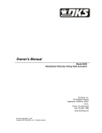
RECOMMENDED SITE LAYOUT EXAMPLE
PLEASE USE ALL SAFETY DEVICES THAT MAY APPLY TO YOUR INSTALLATION TO ACHIEVE THE SAFEST
OPERATION.
(THIS IS A VIEW FROM ABOVE GATE)
SAFETY PHOTO BEAM
STOP PHOTO BEAM
(NOTE-2)
STOP EDGE (NOTE-2)
(NOTE-1)
STOP EDGE (NOTE-2)
GATE STOPS
HERE
EDGE SENSOR (NOTE-2,3) STOP EDGE (NOTE-2)
REVERSING PHOTO BEAM
STOP PHOTO BEAM
(NOTE-2,3)
(NOTE-1)
GATE OPERATOR
ROADWAY SAFETY ZONE
REVERSING PHOTO BEAM
BACKFRAME SAFETY ZONE
(NOTE-2)
STATIONARY/FIXED/DEAD PANEL
STOP EDGE (NOTE-2)
STOP EDGE (NOTE-2)
GATE STOPS
HERE
EDGE SENSOR (NOTE-2,3) STOP EDGE (NOTE-2)
REVERSING PHOTO BEAM (NOTE-2,3)
STOP PHOTO BEAM
(NOTE-1)
GATE OPERATOR
= CONTACT EDGES
NOTE-1. SECONDARY ENTRAPMENT DEVICE (UL-325, SECTION 30A.1.4)
NOTE-2. MAYBE ADDED AS A THIRD LEVEL OF SAFETY BUT IS NOT TO REPLACE BEAMS MARKED NOTE-1.
NOTE-3. REVERSING EDGE OR BEAM WILL RE-OPEN A CLOSING GATE (USE J5 #5)
NOTE-4. STOP EDGE WILL STOP GATE WHILE CONTACTED (USE JP2 CONNECTION)
NOTE: UL-325 SECTION 30A.1 THIS UNIT TO EMPLOY:
PRIMARY ENTRAPMENT IS AN “A1” INHERENT ENTRAPMENT SENSING SYSTEM WITH AN AUDIO ALARM.
(REVERSES GATE DIRECTION) .
SECONDARY ENTRAPMENT IS A “B1” A NON-CONTACT, PHOTOELECTRIC BEAM OR EQUIVALENT, CONNECT AT
JP2. (STOPS GATE SEE NOTE-1).
AT LEAST ONE SECONDARY “STOP” PHOTO BEAM SHOULD BE INSTALLED ALONG THE GATES PATH THAT IS
COVERED WHEN OPEN.
PHOTO BEAMS ARE TO BE INSTALLED ACCORDING TO THEIR MANUFACTURES INSTRUCTIONS AND ARE TO
BE PLACED IN AREAS THAT POSE A RISK OF ENTRAPMENT.
THIS DRAWING IS NOT TO SCALE
It is recommended that all gates & operators be installed to conform to the latest
ASTM F2200-02 requirements! (FOR MORE INFORMATION, GO TO OUR WEB SITE).
Page A3
SAFETY RECOMMENDATIONS
Automatic gate operators can produce high levels of force, therefore it is very important that all gate operator system
installers & designers are fully aware of potential hazards that exist with an incorrectly installed or designed system.
The internal safety capabilities of a gate operator system are not enough to reduce the risk of injury. The operator is only
one part of a properly installed system, which when combined with correctly installed safety devices will yield a complete
system that will not only provide convenience and security, but will be safer with a minimal risk of injury.
The following information along with the check list ( and the rest of the manual) is provided to make you aware of potential
areas that are of a safety concern. Disregarding any of the following may result in serious injury or death.
TWO WARNING SIGNS SECURELY INSTALLED ON EACH SIDE OF GATE PANEL. (REQUIRED)
1 0R 2 SAFETY PHOTO BEAMS INSTALLED, ONE ACROSS EACH SIDE OF GATE OPENING.
1 OR 2 STOP PHOTO BEAMS INSTALLED ON EACH SIDE OF FIXED GATE PANEL (BACK AREA).
PHOTO BEAMS INSTALLED ACCORDING TO THEIR INSTRUCTIONS & IN AREAS THAT POSE ENTRAPMENT RISK
CUSTOMER ADVISED THAT GATE IS FOR VEHICULAR TRAFFIC ONLY. (REQUIRED)
A SEPARATE PEDESTRIAN ENTRY AND / OR EXIT IS PROVIDED. (REQUIRED)
CONTACT EDGES INSTALLED AND FUNCTIONAL AT ALL HAZARD OR PINCH POINTS.
SAFETY GUARDS INSTALLED COVERING ALL CANTILEVER WHEELS. (REQUIRED)
ARE ALL CONTROLS LOCATED FAR OUT OF REACH OF GATE, FIXED PANEL & OPERATOR. (REQUIRED)
IS THIS CLASS OPERATOR APPROVED FOR THE APPLICATION OF THE OPERATOR (CLASS 1,2,3,4) (REQ).
A 2 1/4” DIA. SPHERE CANNOT BE PUSHED THROUGH THE GATE/FIXED PANEL UP TO 4’ FROM GROUND (REQ)
IF SO, IS A SAFETY SCREEN/ MESH INSTALLED WITH A MIN. HEIGHT OF 4 FT. FROM GROUND INSTALLED.
ARE CONTROLS INTENDED TO RESET GATE AFTER OBSTRUCTED INSTALLED IN LINE OF SIGHT.(REQ)
HARD WIRED CONTACT SENSORS LOCATED & WIRED TO AVOID ANY MECHANICAL DAMAGE.
CUSTOMER INSTRUCTED AND IS CLEAR ON PROPER USE OF GATE OPERATOR. (REQUIRED)
CUSTOMER INSTRUCTED ON PROPER USE OF ALL CONTROL DEVICES USED WITH OPERATOR.
SAFETY INSTRUCTIONS WERE REVIEWED AND LEFT WITH CUSTOMER. (REQUIRED)
DID INSTALLER OFFER A PREVENTATIVE SERVICE/MAINTENANCE CONTRACT.
A PHOTO OF COMPLETED INSTALLATION TAKEN FROM FRONT AND BACK OF GATE & DATED.
ADVISED CUSTOMER THAT FOR MANUAL OPERATION THEY MUST DISCONNECT BATTERIES & AC POWER.
IF INSTALLING THIS UNIT ON A GATE THAT ALLOWS A 2 1/4” SPHERE TO PASS THROUGH IT, THE GATE MUST
BE CORRECTED BEFORE THE UNIT IS PUT INTO OPERATION.
DO NOT DISCONNECT THE SIREN IN ANY WAY- SWITCH S1#6 MUST STAY ON & S1#8 MUST
STAY OFF. TAMPERING WITH THE SIREN OF SWITCH SETTINGS MAY POSE THE RISK OF
SERIOUS INJURY OR DEATH. (NOTE: DOES NOT APPLY TO VERSIONS 6.30 OR HIGHER.
THESE SWITCHES WERE REDIFINED FOR NEW FUNCTIONS. THE SIREN CANNOT BE
DISABLED BY CHANGING THESE SWITCHES ON 6.30 OR HIGHER)
Page A4
INTRODUCTION
UNIT OVERVIEW
The DC SOLUTIONS model MEGA-SLIDE-UL slide gate operator is unique in the industry. Setting
the MEGA-SLIDE-UL apart are many features that make it the front runner in its class. With
standard features like:
•
•
•
•
•
•
•
•
•
•
•
•
•
•
•
•
•
•
•
•
•
•
•
•
•
•
•
•
•
•
•
Built in battery backup - inherent 24 VDC backup power with regulated 24VDC for accessories.
High torque 1/2 HP 24 volt Permanent Magnet DC motor .
Full service controller with eight inputs and LED indicators for loops, card reader, radio, etc...
Continuous duty operation for most types of gates.
Reversible gate direction for right or left handed operation.
Instant Reverse Device (IRD) monitor senses obstructions going open and close.
Automatic open of gate when power is lost if desired (With 15 sec. delay selection).
ANTI-TAIL GATE with QUICK CLOSE feature STOP gate in close travel if tail-gating is sensed
Upon complete system failure (lightning, surges, etc...) gate can be pushed open by hand.
All rust proof aluminum construction with baked on powder coat enamel.
Molded Polyethylene UV stabilized cover never needs wax or paint.
Direct drive gear reducer eliminates many parts that might otherwise fail.
Microprocessor (RISC) based electronics with watch dog reset timer.
State of the art MOSFET motor drive technology, NO contactors or relays.
Dynamic motor braking to preserve gate stopping points.
Soft start and stop in open and close travel motions.
High reliability micro switches actuate through nylon limit nuts on a precision ground shaft.
Maximum Run Timer for motor (MRT) with anti-tamper protection in closing direction.
Each unit configurable as master or slave operator.
Safe 24 VDC low voltage motor and control wiring.
Open architecture PCB with space for OVERDRIVE CPU for future expanded options.
LED diagnostic center for easy on-site trouble shooting.
Closing timer adjustable from 1-33 seconds with on / off selection.
Tranzorb diodes on all inputs for protection against transient voltage spikes.
Capable of being powered by 120 VAC, 220 VAC or Solar power, standard.
Duplex outlet gives convenient supply of 120 VAC for transformers and 120 VAC accessories.
Maximum weight of 1000 lbs. Maximum length of 32 feet. (Free moving operation)
10 year perforation warranty on cover and chassis with 2 years on electronics and mechanism.
Input for safety edge device to reduce the possibility of entrapment -recommended.
Input for non-contact sensing device (photo beam) for secondary entrapment protection.
UL Listed device. (Standards certified by UL are UL-325, UL-991)
Page 1
PRE-INSTALLATION NOTES!
NOTE: BEFORE ATTEMPTING ANY PART OF THE INSTALLATION, YOU MUST READ THE
ENTIRE INSTRUCTION MANUAL FIRST AND AGREE TO THE STIPULATIONS STATED ON
THE WARRANTY PAGE.
PROPER DESIGN: Is important in your system layout and installation. Safety devices must be used
at all available points where injury or property damage may occur. For protection from injury to
persons, use photo electric eyes on both sides of gate and pressure sensing edges at all pinch points
and at the front leading edge of the gate. Safety loops (vehicle detectors) should be installed in front
of and behind the gate to provide a reverse signal or stop signal to the gate operator. On cantilever
gates, all wheels should be enclosed so that fingers cannot reach pinch points between the gate and
wheels. ALL SAFETY DEVICES SHOULD BE TESTED AND INSPECTED WEEKLY. IF A SAFETY
DEVICE IS NOT OPERATING CORRECTLY, THE UNIT SHOULD BE DISABLED UNTIL REPAIR
CAN BE MADE BY A PROPERLY TRAINED / EXPERIENCED SERVICE COMPANY.
As the system designer/installer, you must advise your customer/end user on the correct usage of the
gate operator and the system. In providing the service of design/installation of the operator and
system, you are responsible for proper training of the customer as well as for the proper SAFE
OPERATION. All precautions to eliminate ALL hazards MUST be taken before the unit can be put
into operation. You MUST advise and warn your customer of any hazards that remain or if they
choose to not use any of the recommended safety devices in the installation.
YOU ARE STRONGLY ADVISED TO GET IN WRITING FROM YOUR CUSTOMER THEIR
ACCEPTANCE OF YOUR SYSTEM AND ACCEPTANCE OF ANY HAZARDS THAT REMAIN.
SAFETY TIPS:
1) Install the warning signs provided so that they are CLEARLY VISIBLE to
any one in the area of the gate. (should your customer reject the usage of the
warning signs, you are strongly advised to have them sign a disclaimer).
2) Install any and all devices that will open or close the gate so that the entire
gate and operator will be in full view by the person operating the gate.
3) DO NOT ALLOW any control device to be located so that a person can
access them by reaching through the gate pickets.
4) Installing a pressure sensing edge (safety edge) at front of gate to reduce
the possibility of entrapment (use J5 terminal #5 and common).
CAUTION:
FOR USE ON A GATE WITH A MAXIMUM WEIGHT OF 1000 POUNDS
AND A MAXIMUM LENGTH OF 32 FEET. NO BINDING IS ALLOWED, GATE MUST
BE FREE MOVING. IT IS HIGHLY RECOMMENDED THAT HIGH QUALITY WHEELS
WITH SEALED BEARINGS BE USED FOR ALL APPLICATIONS.
Page 2
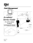
INSTALLATION PROCEDURE
CONCRETE PAD
The concrete pad for operator mounting should be approximately 24"x24"x24" in order to provide adequate
weight and structure to insure proper and stable operation. Pad should be 6" above finished grade (street
level) or 6"above top of curb if one is present. Be sure to position pad so that it is not so close that it will
interfere with the wheel mounting / axle bolts on the gate or that it is so far away that the rear mounting holes
in the base will be too close to the edge of the concrete form.
(NOTE: PAD MUST ALWAYS EXTEND BELOW THE FROST LINE IN AREAS WHERE THE GROUND FREEZES!!)
ANCHORS
Proper anchors for fastening operator to pad will be a 1/2"x6" wedge anchor patterned to match the mounting
base of the unit. They should be installed with approximately 1" showing above concrete surface in order to
1
allow for the /4" thick base plate as well as washers for leveling. Mounting hole pattern is 8.25" wide by 9.125"
deep. The rear mounting hole centers (nearest to gate) will need to be between 5.25" and 7" from gate if the
chain brackets that are provided are to be used (based on a gate with a 2" x 2" box tubing frame).
CONDUITS
The area available in base of unit to position conduits is 10.75" wide by 7.25" deep. All conduits must be cut
down to 1.5" in height to allow for the insertion of the equipment accessory shelf. The equipment accessory
shelf maybe installed after all conduits are cut to proper height and all wiring has been properly routed.
(NOTE: Do not attempt to hook up the 120VAC mains if wires are LIVE or HOT. Be sure power is off)
CHAIN INSTALLATION
Before beginning to install the chain, be sure that the centerline of the mounting holes in the chain brackets
are 8.5" above the mounting pad. Once the brackets have been installed and that the mounting holes in the
brackets line up with the bottom of idler pulleys, connect one end of the chain to one end of the gate. Next
thread the chain through the idlers and drive sprocket, then attach it to the other end of the gate. Cut chain so
that the chain tensioners will not be adjusted out, allowing for as much future tightening as possible.
SAFETY EDGE INSTALLATION - SEE SAFETY PAGE IN FRONT OF MANUAL
It is highly recommended that a pressure sensing edge (safety edge) be installed at the leading edge and at
all hazard and pinch points of the gate. Choose an edge that will cover the full height of the gate. It should be
installed securely and any coil cord used to send the signal back to the operator should be cut so that excess
cord be eliminated to prevent it from getting tangled in the gate or mechanism. Edges that are to REVERSE &
re-open a closing gate connect to J5 #9 - #12. Edges that are to STOP the gate that is opening or closing will
connect to the 2 pins on the JP2 block near the center of the board.
GATE
5 1/4" MIN.
7"
CHAIN
MAX
ALLOW ENOUGH SPACE BETWEEN
PAD AND WHEEL BOLTS ON GATE
OPERATOR FRAME
7 1/4"
CONDUIT AREA
9 1/8"
10 3/4"
8 1/4"
CONCRETE
PAD
Page 3
NOTE 1: MAXIMUM AMBIENT TEMPERATURE FOR INSTALLATION, 140 F.
NOTE 2: FOR AUTOMOTIVE USE ONLY, NO MOTORCYCLES, BICYCLES OR PEDESTRIANS.
WIRING AND HOOKUP (Only by a qualified electrician/installer!)
120 VAC
Be sure your main power (120vac) is OFF before attempting hookup. The 120 volts AC supply should be
terminated to the wires below the duplex receptacle. Connect the 120 VAC to BLACK wire, Neutral to the
WHITE wire and Ground the GREEN wire. Warning- Do not connect any 120 VAC wires directly to the
terminal strips on the electronic control board. Only U.L. approved 14 AWG ( or larger) 600 volt insulated
wire should be used. A separate UL approved 10 amp circuit breaker should be used for each MEGA-SLIDEUL operator. BATTERIES MUST BE INSTALLED AFTER 120VAC POWER IS TURNED ON. See BATTERY
at page 5 and 120 VAC wiring on page 6.
INPUT COMMANDS (Use common & normally open contacts from devices connected to these inputs)
JP2 INPUT- THIS INPUT WILL STOP THE GATE AND ACTIVATE THE ENTRAPMENT SIREN.
This input is for connection to wired contact edge sensors at pinch points and photo beams that run along
either side the gate panel when in open position (if dead panel is present one beam should run along it)
INPUT COMMANDS-J5 CONNECTOR BLOCK AT TOP OF CONTROL BOARD.
Control wire connections at low voltage terminal strip will be at the top of the electronic control board. Make
connections to the appropriate points for the desired operation. Wires should be U.L. approved 600 volt rated
and at least 18 awg. (They are to be routed through the Nylon wiring loops on the right side of the chassis). All
external control devices must have normally open dry contacts. DO NOT CONNECT ANY DEVICE WHICH
WOULD DELIVER ANY VOLTAGE OF ANY KIND TO THESE TERMINALS.
Terminals 9, 10, 11, 12 are the commons (0 VDC) used to activate the following inputs.
1, 2, 3 OPEN- These inputs will trigger gate open when pulsed or hold gate open with maintained contact.
When released gate will close if closing timer is on or if close input is given.
4, AUXILIARY OPEN-(THIS IS THE WIRED LINE OF SIGHT, INTENDED MANUAL RESET INPUT)
Use this input to reset the unit after a 2nd sequential obstruction is sensed and gate is locked
with siren running. This input normally functions as listed below.
Acts same as 1,2,3, above with S2-6 off. With S2-6 ON this will operate as a pulse-open, pulse-close.
Note: Pulse to close will only work when gate is at full open position.
Version 6.34 or higher only, SIREN will run for 5 minutes after 2nd sequential obstruction, then turn its self
off. Operator will require a reset signal to J5 #4 to re-activate gate. In addition, cycling the AC power switch will
also reset the operator.
5, SAFETY- Safety edge(s) and safety loop input. This function will make the gate reverse and go back to
the open position if it was closing. Input is for all NORMALLY OPEN contact safety devices. This input is
disabled when gate is in the full closed position. Use with vehicle loops, photo beams, sensors.
6, CLOSE- ANTI-TAIL GATE close input. When using a vehicle detector, you must use the presence
contacts (N.O. & C.) This input will QUICK close gate after input is applied and then removed. It will stop the
open cycle and reverse gate to close. (Example: Car crosses over close loop before gate reaches full open
position- gate will reverse and close). (Note: The close input also acts as a safety-stop in that if gate is closing
and a tail-gater is sensed at the close input, the gate WILL STOP its closing motion and not continue to close
until the close input is removed or gate is re-opened).
Page 4
INPUT COMMNANDS (Continued)
7, BACK-AWAY (FOR BARRIER ARM GATE ONLY) This input is recommended for use with our Mega Arm
barrier gates. For your Mega Slide-UL, please use terminals 1,2 or 3 for your free exit loop input.
8, SHADOW LOOP- This input operates as a hold open only when gate is a full open position.
9, 10, 11,12- COMMON- These inputs used for common (0 VDC) to above listed functions.
Note: J5 inputs 1-8 are tied to LED indicators to assist in trouble shooting.
3-BUTTON CONTROL STATION (VERSION 6.41 OR HIGHER ONLY)
J5 INPUT #1
J5 INPUT #6
OPEN
CLOSE
STOP
JP2 CONNECTOR
(NOTE: SIREN WILL SOUND WHEN
STOP BUTTON IS DEPRESSED)
J5 COMMONS #9-12
ACCESSORY CONNECTIONS
These terminals will provide battery backed power to 24 VDC devices and are located at the bottom of the electronic
control board at terminals 1 and 2. Terminal 1 is 24 VDC (+) and number 2 is 0 VDC (-). Peripheral CLASS 2 low voltage
devices that require 24 VDC power maybe connected here (500 ma. maximum). EXAMPLE: Vehicle detector, radio
receiver.
RELAY OUTPUT K1- (FOR CLASS 1 & 2 INSTALLATIONS, DO NOT DISCONNECT SIREN.
S1-6 MUST BE ON AND S1-8 MUST BE OFF. ---DO NOT CHANGE—6.30 and earlier versions)
BATTERY INSTALLATION
HOOKING UP BATTERY LEADS- ALWAYS HOOKUP AND TURN ON AC POWER
BEFORE INSTALLING BATTERIES. After turning on AC power, install two NEW, fully charged 12 volt DC
batteries on shelf next to motor. Connect red lead from operator to the positive (RED +) terminal of one battery and black
lead from the operator to the (BLACK-) terminal of the OTHER battery. Place a jumper between the remaining terminals of
each battery if one is not already in place. See diagram below.
12 VDC BATTERY
7-10 AMP
-
BLACK LEAD
+
JUMPER
12 VDC BATTERY
-
7-10 AMP
RED LEAD
+
Failure to install batteries correctly will cause damage and WILL not be covered by warranty.
Page 5
120 VAC POWER CONNECTION
DUPLEX
OUTLET
BOX
CONNECT 120 VAC TO THE 3 WIRES THAT
COME OUT FROM THE BOTTOM OF THE
DUPLEX OUTLET BOX.
120 VAC (BLACK)
GROUND
(GREEN)
NEUTRAL
(WHITE)
MASTER SLAVE WIRING
Master-slave wire hook up.
STEP 1- In a master/slave configuration, either unit can be the master. Choose one unit to be the master and
then direct all control wiring to it (also install vehicle detector and receivers in it).
STEP 2- At the MASTER, any input (at J5) with control (detectors, receivers, keypads, timers, etc...) wires to
it must also be run to the same terminals of the slave. Along with these control wires, both operators MUST
share a common ground connection from chassis to chassis (or from common to common , i.e. master gate
J5 terminal #12 to slave gate J5 terminal #12)
EXAMPLE: If only open and close are used at master then three wires will run between gates.More may be
needed for additional functions to be used.
CLOSE
OPEN
COMMON
EXAMPLE:
1 2
3 4 5
6 7 8
9 10 11 12
1 2
3 4 5
6 7 8
9 10 11 12
MASTER- J5
STEP 3- If it is required that if one gate senses an obstruction, the other reverses also, then 3 additional wires
must be run between the master J3 and slave J3 as shown below. These connections are for transmitting IRD
(obstruction signals) between both units. This will allow the master or slave to inform the other that a closing
obstruction has occurred and for it to also reverse and open. SET switches on S2, 1-8 the same on both
gates.
RX
GND
TX
1
2
3
4 MASTER - J3
IRD - OBSTRUCTION SIGNAL CONNECTIONS
THE CONNECTIONS TO THE LEFT MUST BE DONE IN ORDER FOR
GATE IRD'S TO WORK CORRECTLY. TERMINAL 1 OF MASTER MUS
GO TO TERMINAL 4 OF SLAVE AND TERMINAL 1 OF SLAVE MUST
GO TO TERMINAL 4 OF MASTER. TERMINAL 2 OF MASTER WILL
GO TO TERMINAL 2 OF SLAVE.
1
RX
2
3
GND
4
SLAVE
- J3
TX
Page 6
TIMERS AND MODE SECTIONS (S1 and S2)
FULL SPEED RUN TIMER- SWITCH PACK S1 (1-5)
To change the FAST SPEED run timer, set the dip switches to add up to the number of feet, minus one foot , for the total
feet of travel across roadway. Example: If road is 15 feet wide, then set dip switches to add up to 14 seconds (dips 2,3,4
are on which is 2 seconds + 4 seconds + 8 seconds = 14 seconds. You must set FULL SPEED to end before the end of
travel and allow the gate to go to the slow speed before stopping.
SECONDS---------- 1
2
4
8
16
S1
SHOWS DEFAULT SETTINGS
1
2
3 4
5
FAST RUN TIMER 1-5
6
7
8
| MODE SELECTION 6-8
MODE SELECTIONS- SWITCH PACK S1 (6-8)
SWITCH - 6. FAIL SECURE MODE, (VER 6.351 or higher) with AC power off, in continuous battery back up mode (S2 #8
off) gate will not auto open if batteries get low. If batteries are low, gate will stay open after a open command is given.
SWITCH - 7. NO LONGER USED AS OF 8-16-03. TO BE RE-DEFINED!
SWITCH - 8. NOT USED AT THIS TIME (ver 6.34 or higher only)
CLOSE TIMER- SWITCH PACK S2 (1-5)
On the MEGA-SLIDE-UL the switches 1-5 on S2 are for the closing timer delay. If S2-7 is on, the gate will auto close by
timer. Default is S2-3 "on" to provide a 4 second delay if activated.
SECONDS----------
1
2
4
8
16
S2
SHOWS DEFAULT SETTINGS
1
2
3
4
5
6
7
8
CLOSE TIMER 1-5 | MODE SELECTION 6-8
MODE SELECTIONS- SWITCH PACK S2 (6-8)
SWITCH - 6. Sets aux. open input terminal #4 at J5 to be pulse open--pulse close (example: residential applications).
SWITCH - 7 AUTO CLOSE TIMER. Default is OFF. When on, use S2 1-5 to set close time delay.
When close timer is selected, YOU must install vehicle and pedestrian detection devices. It is strongly recommended that
photo electric beams (eyes) be installed on BOTH sides of slide gate to reduce the possibility of injury to persons that may
attempt to walk through gate opening. Along with the beams, it is strongly recommended that pressure sensing edges be
install leading edge of the gate panel, and any area that presents a PINCH POINT or risk of ENTRAPMENT.
SWITCH - 8 AUTO OPEN ON POWER FAILURE. When switch number 8 is in the ON position, the operator will
automatically open the gate approximately 15 seconds after the loss of power. Once power is restored the operator will
resume normal operation.
Page 7
.
ADJUSTMENTS
RIGHT OR LEFT HAND OPERATION: UNIT SHIPS AS RIGHT-HAND
Method 1: NO LONGER USED AS OF 8/16/03. THE S1-7 SWITCH WILL BE REDEFINED.
Method 2: Reverse the BLUE and ORANGE wire from the motor and at J4 from the limit switches. With this method
DO NOT switch S1-7 to the ON position-leave in OFF position. (SEE PAGE 8A FOR WIRING REVERSAL)
(Wires are read from left to right)
RIGHT HAND OPERATION the motor (J4) and limit switch (J2) wires will be BLUE then ORANGE
(NOTE: RIGHT HAND OPERATION IS THE DEFAULT SETTINGS FROM THE FACTORY)
LEFT HAND OPERATION - the motor (J4) and limit wires (at J2) will be ORANGE then BLUE.
(Wires are read from left to right) (SEE PAGE 8A)
As a RIGHT HAND OPERATOR the LIMIT SWITCH closest to the gear box is the CLOSE LIMIT.
As a LEFT HAND OPERATOR the LIMIT SWITCH closest to the gear box is the OPEN LIMIT.
LIMIT SWITCH ADJUSTMENTS:
It is advised to set limit switches as close as possible BEFORE connecting power. In order to adjust limit nuts, the detent
plate must be pushed down to allow free movement. Spinning the nut closer to the switch will cause the gate to stop
sooner when approaching that switch. Spinning it away will delay the nut in reaching that switch. With power
disconnected, (batteries and AC power) gate can be pushed open and closed to assist in limit switch adjustments. After
initial settings connect power then run gate open and close to fine tune settings.
Remember to set the fast run timer (see page 7) to allow gate to run at the fast speed for as much of the gate travel as
possible, but still ensuring that it will slow down just before reaching the closed position
INSTANT REVERSE DEVICE (IRD):
The instant reverse device is an internal circuit that continuously monitors the motors current for increased draw. While
running gate open and closed, turn IRD1 fully to the left (CCW) then back to the right (CW) in small increments while
obstructing the gate in the closing motion. Set sensitivity to a level that will only reverse gate when an obstruction is
encountered. If obstructed while closing, gate will stop and reverse to the open position, pause until next command then
time out (using the time delay set at S-2 switches 1-5) and then close. If gate is opening when obstructed, gate will stop its
open travel, then close. If inputs are present gate will remain stopped.
WARNING - INSTANT REVERSE DEVICE (IRD) SHOULD BE TESTED WEEKLY TO INSURE
PROPER OPERATION. IF ADJUSTMENTS ARE REQUIRED, REFER TO ABOVE PARAGRAPH.
Page 8
RIGHT OR LEFT HAND OPERATION : METHOD 2 DIAGRAM
NOTE: SWITCH S1-7 MUST BE OFF FOR METHOD #2. (VERSION 6.37 & OLDER)
RIGHT HAND OPERATION -(AS SHIPPED OUT)
ORANGE
GREEN
S3-MANUAL
OPEN
BLUE
RIGHT HAND
J2
GATE
AUX. LIMITS
(OPEN AND CLOSE LIMITS)
OPERATOR
(DEFAULT WIRING SETUP)
X
ACC. POWER
BATTERY
AC XFMR
YOU
MOTOR
RIGHTHAND OPERATION IS VEIWED FROM THE SAME SIDE OF THE GATE
+ _ _ +
24VDC
BLK
RED
AS THE OPERATOR WITH THE OPERATOR TO YOUR RIGHT
YEL YEL
ORANGE
NOTE: UNIT SHIPS OUT AS A RIGHT HAN
BLUE
BLUE
LEFT HAND OPERATION
S3-MANUAL
OPEN
GREEN
ORANGE
LEFT HAND
J2
GATE
AUX. LIMITS
(OPEN AND CLOSE LIMITS)
OPERATOR
X
YOU
ACC. POWER
BATTERY
AC XFMR
MOTOR
LEFTHAND OPERATION IS VEIWED FROM THE SAME SIDE OF THE GATE
+ _ _ +
24VDC
BLK
RED
AS THE OPERATOR WITH THE OPERATOR TO YOUR LEFT
YEL YEL
BLUE
ORANGE
Page 8 A
TROUBLE SHOOTING AND MAINTENANCE PROCEDURES
WARNING - DISCONNECT BATTERIES AND AC POWER BEFORE
SERVICING ANY MECHANICAL OR MOVING COMPONENTS!!!!
BATTERY CHECKOUT- . When the batteries become weak the gate will begin to run noticeably
slower. (Note: Batteries should only be checked when you are sure they have had adequate time to
fully charge). Turn off the AC power and run gate for 5 to 10 cycles while observing low battery
indicator LED D12. If LED 12 comes ON, batteries are too weak to function properly. If LED 12 does
not light, then voltage should be checked as they still maybe near failure. Correct voltage is
approximately 25.5VDC. (Note: If LED D12 does light, gate will open to conserve batteries in this test
or in a real power loss, even if mode switch 8 on S2 is off). Return of AC power will clear low battery
indicator. Correct charge voltage is 27.5 VDC with batteries not connected (adjustment is at R63).
GATE WILL NOT CLOSE
1) Check for any active inputs, AC power loss, AC power switch is off or weak batteries.
2) Check that batteries are connected properly.
3) Is switch S-3 in on position (this is manual open switch).
4) Check for S-2 switch number 8 is in on position and if AC power is lost, see LED D14.
5) Check LED D12, if lit and AC power is off, then batteries needs to be charged or replaced.
GATE WILL NOT OPEN
1) Check for AC power loss at D14 (check AC power switch) and that batteries are fully charged.
2) Check fuses and if inputs are wired correctly, test S-3 manual open switch.
GATE DEAD, NO OPERATION
1) Check LED D14 for AC power indication and check AC power switch is on.
2) Check LED D11 for Heart Beat pulses, if none and D14 (AC) & D5 (Brake) are on, then gate
has repeatedly sensed obstructions. Clear obstruction then clear with next new input.
3) IRD (D2) LED is flashing, MRT has expired. Gate was unable to reach the closed limit switch.
Check that fast run timer is set to run as long as possible. (MRT is Maximum Run Timer).
FUSE(S) ARE BLOWN, F-3 (10 AMP AC) AND / OR F-4 (15 AMP DC)
1) Check for shorts in wiring. If F-3 AC fuse is blown then batteries may also be dead.
"Warning- For Continued Protection Against Fire,
Replace Only With The Same Type And Rating Of Fuse".
GATE CLOSES THEN REVERSES
1) See IRD adjustments, also check for obstacles in gate travel, trees, sticks, rocks, etc......
2) Charge voltage to batteries too low, adjust at R63. With batteries disconnected set to 27.5.
IRD OBSTRUCTION SIGNAL TO OTHER GATE NOT WORKING CORRECTLY
1) Remove connector at J3, obstruct gate, LED D13 should go off for a few seconds. This indicates
signal was transmitted. Be sure gates share a common ground (See master slave pg. 4)
GENERAL SERVICE
1) Belt loose or needs replacement, adjust with 4 bolts that support motor to allow 1/4 inch play.
2) Charge voltage for batteries should be 27.5 VDC with batteries disconnected. (set at R63)
3) Replace batteries with Yuasa, pn# NP7-12, 7 or 10 amp hour 12vdc sealed lead / acid type.
Page 9
SAMPLE CONFIGURATIONS
FREE EXIT ON VEHICLE APPROACH:
OPEN LOOP
SAFETY
LOOP
GATE WILL OPEN WHEN SENSED BY
OPEN LOOP AND THEN CLOSE ONCE
ALL LOOPS ARE CLEARED IF THE
CLOSE TIMER IS ON. CLOSE INPUT CAN
USED TO CLOSE GATE BEFORE TIMER EX
TERMINAL # 1,2,3 IS OPEN INPUT.
TERMINAL # 5 IS SAFETY INPUT.
MEGA SLIDE-UL
ENTRY WITH ACCESS CONTROL DEVICE:
GATE WILL OPEN WHEN ACTIVATED BY AN
ACCESS CONTOL DEVICE. WHEN TIMER
EXPIRES (IF USED) GATE WILL CLOSE
SAFETY
LOOP
CARD READER
TELE-ENTRY
RADIO CONTROL
SAFETY
LOOP
TERMINAL # 5 IS SAFETY INPUT.
TERMINAL # 1,2,3 ARE OPEN INPUTS.
MEGA SLIDE-UL
DUAL DIRECTION AS ENTRY AND FREE EXIT:
CARD READER
TELE-ENTRY
RADIO CONTROL
SAFETY
LOOP
OPEN
LOOP
DUAL DIRECTION IS A COMBONATION OF
BOTH OF THE ABOVE CONFIGURATIONS
TO PROVIDE THE ABILITY FOR TRAFFIC
TO ENTER OR EXIT IN THE SAME LANE.
MEGA SLIDE-UL
DO NOT ALLOW CONTROL DEVICES TO BE WITHIN 10 FEET OF GATE OR OPERATOR
RECOMMENDATION 1: If vehicle detectors are used to open or close the gate, use of the presence
contacts are recommended. Using the pulse contacts will REDUCE the gates safe operation.
RECOMMENDATION 2: Use safety pressure sensing edges to prevent entrapment.
RECOMMENDATION 3: Install ALL access control devices within view of gate.
PAGE 10
CONTROL BOARD LAYOUT
BOARD REV 2.0 (2/98)
READ SAFETY INSTRUCTIONS BEFORE WIRING
USE JP2 FOR "STOP" PHOTO BEAMS
USE J5 #4 FOR INTENDED RESET INPUT
OPEN GATE INPUTS-READER, PUSH BUTTON
AUX OPEN RESET (PULSE OPEN/CLOSE)
SAFETY INPUT
CLOSE GATE INPUT-CLOSE LOOP
(EXTERNAL LIMIT INPUTS)
MASTER/SLAVE
J2
BACK AWAY-FREE EXIT LOOP
S3-MANUAL
OPEN
J5
TX
D13
J3
INTERLOCK MEMORY
COMMONS - 0VDC
1
2
3
4
5
6
7
8
9
10 11 12
MODE 5-8
S 1
FAST RUN 1-4
S 2
CLOSE TIMER 1-5
MODE 6-8
1
2
3
4
5
6
7
OPEN LIMIT SENSOR
D7
U3
OPEN DRIVERS ON
D6
OVER
DRIVE
CPU
MOTOR BRAKE ON
D5
CLOSE DRIVERS ON
D4
CLOSE LIMIT SENSOR
D3
U5
BATTERY CHARGE
CPU
Q6
IRD1
JP2 (PHOTO BEAM)
F1
D2
D11
D1
Q5
MOSFETS
AC OK
BATTERY LOW
OBSTRUCTION SENSE
(IRD AND MRT)
8
R63
I/O INTERFACE PORT
D12
D14
H BEAT
1 AMP-DC
Q4
F4
15 AMPS
F3
10 AMP
Q3
RELAY INDICATOR
ACC. POWER
RELAY (OPTIONAL)
BATTERY
AC XFMR
MOTOR
YEL YEL
BLU
K-1
J1
K-1 RELAY
TERMINALS
+ _ _ +
24VDC
{REQULATED}
BLK
RED
ORG
HEAT SINK
1-C, 2-NC, 3-NO, 4-24VDC+ {REGULATED}
ACCESSORY POWER IS 24VDC REGULATED RATED AT 500 ma. [1/2 AMP]
{POWER AT ACCESSORY+ AND AT K1 RELAY PIN-4(+) IS FUSED AT F1 WITH A 1 AMP FAST-BLO FUSE}
J5 #4 FOR USE WITH HARD WIRED LINE OF SIGHT DEIVICES TO OPEN GATE AND RESET UNIT.
D11- HEART BEAT- SHOWS THAT PROCESSOR AND PROGRAM ROUTINE ARE RUNNING PROPERLY
D12- BATTERY STATUS- SEE DIAGNOSTIC PROCEDURES ON PAGE 9.
D14- AC POWER INDICATOR- SHOWS THAT AC POWER IS PRESENT
S3- MANUAL OPEN- TO ALLOW GATE TO BE OPENED OR CLOSED DURING SERVICE OF UNIT.
F1- 1 AMP FAST BLO FUSE (5mmX20mm). MAXIMUM CONTINUOUS DRAW IS 1/2 AMP. (U.L. LISTED FUSE ONLY)
F3- 10 AMP ATO TYPE FUSE FOR 24VAC INPUT POWER. (U.L. LISTED FUSE ONLY)
F4- 15 AMP ATO TYPE FUSE FOR 24VDC BATTERY INPUT POWER. (U.L. LISTED FUSE ONLY)
JP2- INPUT FOR PHOTO BEAM AS A SECONDARY ENTRAPMENT PROTECTION
Page 11
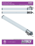
MEGA SLIDE-UL. PARTS LIST
12
5
INSIDE VIEW 19
6
22
13
7
9
DCS
1/2
HP
20
16
10
21
ITEM PN
MS-001-UL
MS-002
MS-003
MS-004
MS-005
MS-006
MS-007
MS-010
MS-009
MS-351
MS-041
MS-043
MS-013
MS-014
MS-015
MS-016
MS-017
MS-018
MS-019
MS-040
MS-021
MS-044
MS-023
MS-020
MS-202
11
15
8
3
1
2
3
4
5
6
7
8
9
10
11
12
13
14
15
16
17
18
19
20
21
22
*
*
24
REAR VIEW
14
1
24
18
DESCRIPTION
CONTROLLER-CPU
J5 CONNECTOR (ON PCB, NOT SHOWN)
½ HP HIGH TORQUE MOTOR - 24 VDC
12VDC 7AH BATTERY-2 REQUIRED (NOT INCLUDED)
GEAR REDUCER 10:1
¼ “ ALUMINUM CHASSIS (FRAME)
DRIVE BELT
REDUCER PULLEY 5”
MOTOR PULLEY 2”
MOTOR BREAKER / DISCONNECT
DRIVE GEAR
LIMIT NUTS
DETENT PLATE
SIREN (100 db)
TRANSFORMER (110 / 220 VAC-24VAC)
DUPLEX OUTLET
BOLT & NUT (4) REDUCER (NOT SHOWN)
IDLER PULLEY BOLT, WASHER, NUT
120 VAC ON-OFF SWITCH
IDLER PULLEY (UHMW)
REMOVABLE ACCESSORY SHELF
LIMIT SWITCH
PLEXI WINDOW (WITH BEND. NOT SHOWN)
UNIT COVER
#41 NICKEL PLATED DRIVE CHAIN (10 FT COILS, 2 REQ)
PARTS SHIPPED
1
MEGA SLIDE-UL OPERATOR
1
CONTROLLER CPU (MS-001-UL)
1
UNIT COVER (MS-020)
1
ACCESSORY SHELF
1
INSTALLATION AND SERVICE MANUAL
2
GATE PULL TABS WITH HARDWARE (MS-205 PULL TABS, MS-204 CHAIN BOLT)
1
20 FEET OF #41 NICKEL PLATED DRIVE CHAIN (10 FT COILS, 2 REQ. MS-202)
2
WARNING SIGNS
UNIT ALSO REQUIRES (2) SEALED 12 VDC 7-AMP HR OR 10-AMP HR BATTERIES- NOT INCLUDED
Page 12
(You must read, understand and agree with all items in the limited warranty)
INSTALLATION CHECK-OFF LIST MUST BE COMPLETED
ANY REQUIRED CONTACT EDGES & PHOTO BEAMS
MUST BE INSTALLED
LIMITED WARRANTY
DC SOLUTIONS, INC. Warrants the MEGA SLIDE-UL to be free of defects in workmanship and materials
for a period of 2 years for electronics & mechanical components and includes a 10 year corrosion perforation
warranty on the cover and chassis (Cosmetic appearance is not included). Warranty will begin from the date of
purchase.
DC Solutions, Inc. reserves the right of final determination as to the existence and causes of any defect or
failure. Any part or parts found to be defective and are returned to DC Solutions within the warranty period,
shall at our option be repaired or replaced free of charge F.O.B. the factory. Freight is not included at any time
on gate arms & chassis. ONLY UPS ground freight is included during the first year of warranty.
The warranty will not apply the following circumstances which are considered beyond our control.
Mis-use, vandalism, accident, neglect, unauthorized repairs or modifications, acts of God (lightning, floods,
insect damage, etc...), power surges, units subjected to corrosive environments, incorrect installation or
application, the batteries or incorrect battery installation, operation without or failure to use correct battery
type, damage to mechanism due to wrong type of gate, incorrect weight, gate not operating freely or not on
level ground.
The warranty set forth above is entirely exclusive and no other warranty whether written or oral, is expressed
or implied. DC Solutions, inc. specifically disclaims any and all implied warranties, merchantability or fitness for
a particular purpose. It is the purchasers sole and exclusive responsibility to determine whether or not the
equipment will be suitable for a particular purpose. In no event shall DC Solutions, inc. be held liable for direct,
indirect, incidental, special, consequential damages or loss of profits whether based on contract, tort, or any
other legal theory during the course of the warranty or at any time there after. The installer and/or end user do
agree to assume all responsibility for all liability in use of this product, releasing DC SOLUTIONS, INC of all
liability.
WARNING
!
MEGA SLIDE-UL IS NOT FOR USE WITH MOTOR CYCLES, BICYCLES OR PEDESTRIANS.
YOU MUST PROVIDE APPROPRIATE SIGNAGE BEFORE ACTIVATING THE UNIT.
NEVER ALLOW CHILDREN TO PLAY NEAR OR OPERATE AUTOMATIC GATES.
INSTALL PHOTO BEAMS AND PRESSURE SENSING EDGES AT ANY AREA THAT COULD POSE A
HAZARD TO PEDESTRIAN OR VEHICULAR TRAFFIC.
IN ORDER TO INSTALL AND USE THE MEGA SLIDE-UL, YOU MUST UNDERSTAND AND BE IN FULL UNCONDITIONAL
AGREEMENT WITH ALL STIPULATIONS OUTLINED ABOVE. IF YOU ARE NOT IN FULL AGREEMENT, DO NOT PUT UNIT INTO
OPERATION. IF OPERATOR IS PUT INTO OPERATION THIS WILL BE CONFIRMATION THAT YOU ARE IN FULL
UNCONDITIONAL AGREEMENT WITH ALL OF THE ABOVE STIPULATIONS.
Materials, components, features and specifications are subject to change without notice.