1
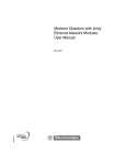
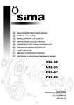
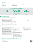
All rights reserved.
The information and instructions in this manual are subject to print errors and misspelling. No rights can be
derived from the information contained herein.
Version 2.0
Ventilair Group Nederland
2
Table of Contents
I
Glossary ....................................................................................................................................................................................... 4
II
2.1
2.2
2.3
2.4
2.5
2.6
2.7
2.8
Introduction ................................................................................................................................................................................. 5
Why should you ventilate?............................................................................................................................................................. 5
System D with ground heat exchanger ........................................................................................................................................... 5
Operation of the Aquacom ............................................................................................................................................................ 5
Aquacom advantages .................................................................................................................................................................... 5
Safety ........................................................................................................................................................................................... 5
Warranty ...................................................................................................................................................................................... 6
Liability ......................................................................................................................................................................................... 6
Deliveries ...................................................................................................................................................................................... 6
III
3.1
3.2
3.3
3.4
User's manual ............................................................................................................................................................................... 7
Controlling the Aquacom ............................................................................................................................................................... 7
Tips for using the Aquacom............................................................................................................................................................ 8
Maintenance by the user ............................................................................................................................................................... 8
Recycling of the Aquacom .............................................................................................................................................................. 9
IV
4.1
Installers manual ........................................................................................................................................................................ 10
Mounting of the Aquacom ........................................................................................................................................................... 10
4.1.1 Installation of the glycol-water ducts ................................................................................................................................... 10
4.1.2 Mounting of the Aquacom................................................................................................................................................... 11
4.1.3 Drain connection ................................................................................................................................................................ 12
4.1.4 Connection of the air ducts ................................................................................................................................................. 12
4.1.5 Connecting the water-glycol ducts to the Aquacom and filling them. ..................................................................................... 12
4.2 Setting the Aquacom ........................................................................................................................................................................ 13
4.2.1 Setting the Aquacom ........................................................................................................................................................... 13
4.2.2 Setting the external fan ....................................................................................................................................................... 15
4.3 Operation of the control unit ............................................................................................................................................................ 15
4.3.1 Operation of the control unit during summer operation ....................................................................................................... 15
4.3.2 Operation of the control unit during winter operation .......................................................................................................... 15
4.3.4 Pump protection ................................................................................................................................................................. 15
4.4 Maintenance by the installer ............................................................................................................................................................ 15
4.4.1 Pressurizing ........................................................................................................................................................................ 15
4.4.2 Check the glycol content ..................................................................................................................................................... 16
4.4.3 Check the heat exchanger ................................................................................................................................................... 16
4.4.4 Cleaning the heat exchanger block....................................................................................................................................... 16
4.4.5 Cleaning the drain ............................................................................................................................................................... 16
4.4.6 Check the pump operation .................................................................................................................................................. 16
4.4.7 Check (and if necessary repair) the electrical wiring. ............................................................................................................. 16
V
Error Messages ........................................................................................................................................................................... 17
5.1 Messages on the display................................................................................................................................................................... 17
5.2 Error schemes .................................................................................................................................................................................. 18
5.2.1 General error ...................................................................................................................................................................... 18
5.2.2 Sensor error........................................................................................................................................................................ 19
5.2.3 Error data transfer .............................................................................................................................................................. 20
5.2.4 No heating .......................................................................................................................................................................... 21
VI
Aquacom specifications .............................................................................................................................................................. 22
6.1 Technical specifications .................................................................................................................................................................... 22
6.2 Drawings ......................................................................................................................................................................................... 23
6.3 List of components........................................................................................................................................................................... 23
6.4 Connection scheme control unit ....................................................................................................................................................... 24
Appendix I: Connecting glycol water duct with PE connector ................................................................................................................. 25
Appendix II: Maintenance by the end user ............................................................................................................................................ 26
Appendix III: Maintenance overview ..................................................................................................................................................... 28
3
I
Glossary
To use the Aquacom correctly, it is important to
know the following definitions first.
amount of supplied and extracted air is adjusted by
the valves.
Ground heat exchanger
A ground heat exchanger is used to preheat the
supply air in the winter and to cool it in the
summer, by using the constant temperature of the
earth. Ducts are placed in the ground, in which a
fluid is circulating. This fluid takes over the
temperature of the ground and is then guided
through a heat exchanger in which the supply air is
heated or cooled.
That is why it is important to keep the same
settings of the valves and to keep the valves at the
same place. It is also important that air can
circulate well in the house, so make sure that
openings under doors are not sealed or reduced.
Balanced ventilation
There is balanced ventilation when there is as
much air extracted from a building than there is
supplied.
Bypass (standard for HRUC-E)
The bypass is used during the summer period, to
extract the heat of a building in the evening or at
night. One of the air flow is not conducted over the
heat exchanger, so the extracted heat is not
transmitted to the supply air flow.
Filter
For an optimum quality of indoor air, the outside
air is conducted through filters before it enters the
building. This keeps the channels of the heat
exchanger cleaner and therefore more efficient.
System D
System D stands for balanced ventilation system
with mechanical supply of fresh air (by fans) and
mechanical extraction of contaminated air. The
4
Cross-flow heat exchanger
The heat exchanger is the part of the Aquacom
where the heat is exchanged between the glycolwater mix and the supply air. It consists of
aluminum plates that are corrugated. Along these
plates, supply air flows without directly coming
into contact with the glycol-water mix. They speak
of cross-flow because the air flow is perpendicular
to the glycol-water flow. This will yield a higher
performance compared to a co-current heat
exchanger.
Frost protection
To prevent freezing of the heat exchanger of a
ventilation unit at temperatures below 0°C, there is
frost protection. By application of a ground heat
exchanger, frost protection will be necessary only
at lower temperatures. Aquacom also has frost
protection, this ensures that its heat exchanger will
not freeze.
Heat recovery (HR)
The heat exchanger of the ventilation unit will
extract the heat of the exhaust air. This heat is
then transferred to the supply air. In this way, heat
is recovered that normally should be blown out of
the house.
II
Introduction
Read this entire manual carefully before installing and/or using the Aquacom.
This guide gives you step by step guidelines for proper and safe installation, operation and maintenance of the
Aquacom. Installation must be performed by a qualified installer. Incorrect or incomplete installation may
cause the system not working properly, which may affect air quality in the house. The installation must be
connected according to local installation instructions.
2.1 Why should you ventilate?
Older houses are often poorly insulated and have
many cracks and crevices. This causes uncontrolled
ventilation, which has a cold draft as consequence.
To combat this, you often turn up the heater,
causing unnecessary energy use. By placing a good
ventilation system with heat recovery in your
house, significantly less heating is required, saving
energy and money. Good ventilation is therefore
absolutely necessary, because our homes are
increasingly insulated and made airtight. If you do
not ventilate adequately in such an airtight house,
problems with moisture and even mold will occur.
These problems do not arise from too much
insulation but rather from insufficient ventilation.
A lot of humidity in a house is also created because
people breathe and perspire, cook, wash and
shower. Besides that, CO2 is liberated when we
cook or heat water on gas. Poor ventilation is
dangerous and unhealthy. To counter CO2
poisoning, mold and dust mites and to create a
healthy environment, you have to ventilate
adequately.
2.2 System D with ground heat exchanger
System D with heat recovery (HR) stands for
balanced ventilation through mechanical supply of
fresh air and mechanical removal of contaminated
air (by fans). The exhaust air passes through a heat
exchanger during winter and there it heats the
fresh air. The fresh, heated, air is then blown into
the house. In the summertime it is possible to
bypass the heat exchanger at night, so that fresh
air can be supply without being heated by the
exhaust air (bypass). If the house is cooler than
outside, the heat is kept out by the heat
exchanger. The main advantage of this mechanical
ventilation system is that the energy from the
exhaust air is used to heat or cool fresh air. This
represents substantial energy and cost reduction
compared to natural ventilation or system C.
To preheat the fresh supply air during wintertime,
a ground heat exchanger is applied. This transfers
the constant ground temperature to the supply air
through a glycol-water mix. During summertime,
the same constant ground temperature cools the
supply air. This also reduces the relative humidity
of the supply air, provided that condensation
appears in the Aquacom.
2.3 Operation of the Aquacom
The ground heat exchanger Aquacom contributes
to a better climate in a home. The unit works as
follows:
1. The fan of the heat recovery unit sucks fresh
outside air through the Aquacom.
2. The pump of the Aquacom pumps a glycolwater mixture through ducts buried in the ground.
This causes the mixture to exchange heat with the
ground.
3. The energy from the mixture is transferred in
the Aquacom air-fluid heat exchanger to the fresh
outside air. This will give preheated air during
winter operation and cooled air with lower
absolute moisture content
during summer
operation.
4. The fresh air will possibly be directed through
the heat exchanger of the heat recovery unit.
5. The fresh air will be blown into the living spaces
of the residence.
2.4 Aquacom advantages
Aquacom will heat up ventilation air during winter,
and cool down during summer, like all ground heat
exchangers. Aquacom is unique because it has two
possible connections to direct the air to the
ventilation-unit. The unit is also mountable on both
the left or the right side because of the removable
cover on both sides. This results not only in a
simplified installation, but also in a reduced
material cost and a reduced air flow resistance.
2.5 Safety
Always follow safety and maintenance
requirements, notes and warnings in this
manual. Failure to do so may cause
personal injury or damage to the Aquacom. Keep
this manual during the lifetime of the unit and
always unplug it before any maintenance or service
is committed to the unit!
5
-
-
-
Installing,
operating
and
effectuating
maintenance of the Aquacom must always be
done by a certified installer, unless minor
maintenance is concerned and is indicated as
such in this manual.
During installation the local and general
applicable building, safety and installation
instructions of the municipality, utilities and
other agencies must be abided.
There should not be made any modifications
to the Aquacom.
We recommend you to close a service
contract, so you are assured of a regular
checks. Contact your dealer for a list of
certified installers.
2.6 Warranty
Comair provides a guarantee of 2 years after
installation to a maximum of 30 months after
production date of the Aquacom. This warranty
applies only to material and/or construction
defects. If there is any defect within the warranty
period, this must be reported to the installer of the
unit.
The warranty on the unit expires if:
1. The warranty has expired.
2. The installation, use and/or maintenance does
not meet the requirements listed in this guide.
6
3.
4.
5.
6.
7.
Major maintenance on the unit was
committed by an unauthorized maintenance
technician.
There are signs of abuse or modifications on
the device.
Changes to the system have been made after
completion of the installation.
Improper tubing is used.
Too little or improper anti-freeze is used.
2.7 Liability
The Aquacom is designed as an addition to a
balanced ventilation system. The unit has to be
placed in a dry, frost-free area . Any other use is
unauthorized and is considered as "improper use".
For damage or injury resulting from this improper
use of the Aquacom, Comair cannot be held
responsible.
In addition, Comair BV not liable for damage or
injury resulting from failure to follow safety,
operating and maintenance instructions as
specified in the installation manual.
2.8 Deliveries
All deliveries are subject to the general conditions
of METAALUNIE. Afree copy will be sent to you
when requested.
III
User's manual
This section of the manual provides the
information to operate the Aquacom correctly,
what to do with an error and how to effectuate
maintenance.
failure occurs, Aquacom will restart in the same
mode in which it was before the power failure.
These buttons can be used to
select the sub- menus in the
main menu. In the different
sub- menus, the values can be
changed using these buttons.
NOTE: Always remove the plug from the
wall socket before servicing the unit!
3.1 Controlling the Aquacom
Aquacom is standard equipped with an Aquacom
digital operating panel which is integrated in the
front of the unit. The installer has installed the
operating panel on the correct side. The control
panel looks like the following figure.
This button is used to confirm your
choice in a (sub) menu.
The control panel will remain in the (sub) menu of
your choice until you change this yourself. The
display however will return to the standard view
after 20 seconds. Below, the menus for the end
user will be explained step by step.
Main menu:
Press
to get into the main menu. The main
menu provides access to the sub menus listed
below:
1. T1 outside
2. T Aquacom
The screen:
When the Aquacom is turned on, the time and
date will be shown on the screen. The next figure
shows the information which will be shown
standard. When the unit is turned off, ' - Unit off -'
will be shown.
Time
16:12
14.07.12
Date
If an error occurs, an error message will be shown,
until the error is resolved. Check section five for
the necessary action. Even though the pump will
continue for most errors, it is important to repair
the error, since the unit does not operate like it is
meant and can be damaged in the process.
The basic control buttons:
The control panel contains four basic control
buttons:
This button is used to turn the
Aquacom on and off. When a power
3. Time
4. Date
5. Pump test
6. P4 code
View outside temp.
View temperature after
heat exchanger
Set time
Set date
Test pump
Access installer menus
Use
and
to select a sub menu. Use
to enter the menu. As long as a menu is not
confirmed, the value is shown which is currently
set.
Sub menu 1 – T1 outside
When this menu is selected in the main menu, the
current value is shown of the temperature of the
outside air, before this enters the heat exchanger.
This value cannot be changed, however this value
can be used when errors occur.
Sub menu 2 – T Aquacom
When this menu is selected in the main menu, the
current value is shown for the air temperature
after the heat exchanger. This value cannot be
changed.
7
Sub menu 3 – Time
After entering this menu, the value of the hour will
start blinking. Using the
and
buttons, this
value can be changed. When this is set correctly, it
can be confirmed by pressing the
button.
Now the minutes value will start blinking, which
can be set in the same way as the hour value.
When this is set correctly, it is confirmed by
pressing
. Now it will return to the time sub
menu, and the specified time can be checked.
Sub menu 4 – Date
After selection of the sub menu with the
button, this sub menu can be changed by pressing
the
button. The day number will now start
blinking. Using the
and
buttons, the value
can be adjusted until the correct value is obtained.
The
button will confirm your setting. Now
the month number will start blinking. This can be
set in the same way as the day number. When the
month number is confirmed by pressing
, the
year number will start blinking. This can be set in
the same way as the day- and year number. When
this is confirmed by pressing
, it will return to
the date sub menu, and the specified date can be
checked.
Sub menu 5 – Pump test
In this sub menu, the pump can be tested. The
usefulness will be explained later in this section.
This menu can be selected by pressing the
button from the main menu. The display will show:
'Pump test?'. When
is pressed, the pump will
be activated for 30 seconds, independent of the
measured temperatures. After 30 seconds, the
display will show 'Pump test end', which can be
confirmed by pressing the
button again, and
it will return to the sub menu pump test.
Sub menu 6 – Code menu
This menu is to be used solely by the installer.
Entering the correct code will grant access to the
sensitive system settings. Read section 4.2.1 if you
are interested in what your installer can set for
you. Make sure your installer is aware of the
settings of the ventilation equipment. The
ventilation settings will influence the settings of
the Aquacom.
3.2 Tips for using the Aquacom
From the moment the Aquacom is attached to
your ventilation system, there are several
situations which should be taken into account
while using the unit.
The ventilation equipment will determine the
amount of air which will be drawn (through
8
-
-
-
-
-
-
the Aquacom unit). When this amount is
higher, more ground energy will be
transferred to the ventilation air. The achieved
temperature rise or drop however will be
lower.
When the Aquacom is turned off, the heat
exchanger can freeze during outside air winter
conditions and a high ventilation flow. Never
unplug the unit from the wall socket,
otherwise the frost protection will not work.
Also make sure enough anti-freeze is added to
the water.
For extreme winter temperatures (< -15°C)
and a high ventilation flow, the heat
exchanger can freeze. When extreme low
temperatures occur, never use the highest
ventilation mode.
When the heat recovery unit is engaged in the
'summer exitair only' mode, no air is drawn
and the Aquacom will not have any effect.
When the ground temperature will not have
any useful effect, the Aquacom will disable
itself. It will also enable itself by itself.
Do not adjust the (potential) bypass
temperature of the heat recovery unit. This
temperature ensures no condensation will
appear in the system.
The Aquacom unit will every two weeks at
least turn on for two minutes when the plug
in the wall socket. This will prevent the pump
from forming rust and getting stuck.
3.3 Maintenance by the user
Major maintenance of the Aquacom should
always be performed by a qualified installer.
Do not try to perform this as an end user.
When performing the requirements below, make
sure the plug is removed from the wall socket.
We recommend to commit every two years the
following the major maintenance on your
ventilation unit:
Check the fins of the heat exchanger for
damage
Clean the heat exchanger
Clean the drain
Check the pump operation
Check (and if necessary repair) the electrical
wiring.
Check the system pressure
Check the glycol content
In addition, we recommend cleaning the duct
system every six years.
Aquacom maintenance for the end user limits itself
to cleaning and replacing the filter. Also the
operation of the Aquacom needs to be checked on
the basis of the different meters. For the
appropriate designation and the location of every
meter you are referred to section 6.3.
Replacement of the filter
The Aquacom unit hold one single filter, since only
the supply air passes through the unit. This filter is
applied to maintain a clean heat exchanger of the
Aquacom unit. If an external ventilation source
also uses filters, it is possible to remove the supply
filter after placement of the Aquacom. The
Aquacom unit itself has no filter message, since
most ventilation units have this. When the
ventilation unit shows a message to change or
replace the filters, this also needs to be done for
the Aquacom. When no message is available, it is
recommended to change the filter every 12 weeks.
The frequency of the cleaning/replacement
however depends on the degree of contamination.
New homes and new ducts contain relatively a lot
of dust. Therefore it is recommended to clean the
filter every two weeks, and every three months
change the filter. When the contamination appears
to be limited, the interval can be increased.
Replacement/cleaning of the filter is done in the
following way:
Disconnect the Aquacom plug from the wall
socket
Disable the external ventilation source so no
pollution will enter the heat exchanger
Open the front cover using the two clip
closures on top of the unit
Lift up the filter on to the foam, and pull the
filter towards you, as shown below:
-
-
-
Clean the plate on which the filter rests.
Possibly there are larger contaminations like
stones and leaves.
Put in the new filter. If there is an arrow on
the filter, this needs to point in the direction of
the heat exchanger.
Close the front cover with the clip attachments
on top
Reconnect the plug of the external ventilation
unit
Reconnect the plug of the Aquacom unit
Record the date of a possible filter
replacement in the schedule on page 31
Check the operation of the Aquacom
To guarantee the proper operation of the
Aquacom, there are several simple things you can
do during cleaning or replacement of the filters. If
you notice a problem during the next actions,
contact your installer.
Check whether the manometer shows the
correct pressure. This should be between 0.8
and 1 bar, and may not be higher than 1 bar.
Check whether the flow meter shows a flow.
In order to do so, make sure the pump is
turned on. For this, the plug must be
connected to the wall socket, watch out for
electricity and cabling! If the pump is off, use
the function pump test as described in section
3.1 sub menu 4. The flow should be 6 l/min. If
the pump is working, but there is no flow,
check whether the main valve, and the valve
on the flow meter are open. Call your installer
in case of a defect pump.
Check for leakage/damage.
3.4 Recycling of the Aquacom
If your Aquacom has come at the end of its
lifetime, do not dispose it in your household trash.
Consult with your supplier what he can do with the
unit. If he cannot take the unit back, ask your
municipality what you can do. Your municipality
has solutions for the recycling of components or
environment friendly processing of the materials.
The Aquacom is mainly made of metal and is
therefore particularly suitable for recycling.
-
Clean the filter with a vacuum cleaner if it
does not need replacement.
9
IV
Installers manual
This section of the manual provides the
information needed to install, program and
maintain the Aquacom unit correctly. Information
about errors and reports can be found in section
five. Put your contact details on the back of this
manual, after installation.
-
-
-
-
Always follow the following requirements
at the installation:
Installing,
operating
and
effectuating
maintenance of the Aquacom must always be
done by a certified installer, unless minor
maintenance is concerned and is indicated as
such in this manual.
During installation the local and general
applicable building, safety and installation
instructions of the municipality, utilities and
other agencies must be abided.
There should not be made any modifications
to the Aquacom.
Never turn on the Aquacom without glycolwater mixture in the system. This can damage
the pump.
-
-
4.1 Mounting of the Aquacom
The Aquacom is designed is such way that only one
version is needed for all possible situations. The
incoming air flow duct has to be attached on the
same side as the pipes for the water glycol mixture.
The outgoing air flow duct can be attached either
on the top or on the side. The Aquacom unit needs
to be attached to the suction side of the fan at all
times. This benefits both the efficiency of the
Aquacom heat exchanger and the required fan
power. Also with connection of the Aquacom to
the press-side of system D ventilation, the
recovered heat from the exhaust air would be
transferred to the glycol water mixture in winter
operation.
The way the Aquacom unit will be mounted can be
chosen on the spot. The unit will standard be
delivered in the recommended configuration for
maintenance. If you wish to change this
configuration, you have to follow the next steps:
Remove the four M8 cap nuts together with
the four rings.
Remove the four rubber caps from the threads
on the other side
exchange the brackets of the side and place
back the rings, the cap nuts and the rubber
caps.
10
Check whether the brackets are attached
correctly and whether its positions are correct.
Remove both covers which are fixed by the
clip closures.
Remove the cable of the control unit from the
cable tie attached to the sheet metal.
Remove the three screws with which the
control units housing is attached to the unit.
Beware, the housing will not be attached to
the unit anymore.
Also remove the fourth screw. The control unit
needs to be attached here on the other side.
Turn the control unit to the other side of the
unit without damaging the cables and screw it
on the other side. Make sure you attach the
cable tie with cables to the sheet metal again.
Rotate the manometer clockwise so it can be
read from the other side.
Rotate the measuring scale of the flow meter
so this can be read from the other side.
Carefully press the blind cover with isolation
out of the rear cover (cover without sticker).
Place the blind cover with isolation in the front
cover (cover with Aquacom sticker).
Place both covers back on the unit.
4.1.1 Installation of the glycol-water ducts
Before you start installation of the ducts, draw a
plan how to install the 200m hose. This way you
will never have too much or too little of the hose.
Keep the following things in mind when drawing
the plan:
Use PE hose with an outer diameter of 25mm,
Comair supplies the correct hose (Art. nr.
1230703).
The maximum applicable hose length is 200m.
The hoses are 100m length per hose. These
can be connected using a PE coupling (Art. nr.
1230704). For proper assembly of the
coupling, see appendix I.
Try to draw the plan in such way that the PE
coupling is inside the house. If this is not
possible, indicate the coupling clearly in the
plan.
Mind the local regulations when placing the
duct, and assure yourself whether you need a
permit to place a horizontal ground heat
exchanger with a glycol-water mixture. Some
municipalities also indicate a maximum depth
for the duct network.
-
-
-
-
-
-
-
The depth of the duct network does not
matter for the pump, since it is a closed
system.
The depth of the duct network has a large
impact on the seasonal temperature. If the
hose is deeper, the temperature will be much
more constant (cool in summer, warm in
winter).
The recommended depth is at least 1.5 meter
deep, preferably in the ground water. Ground
water provides a high thermal refresh rate.
Place the ducts with a distance of at least 0.5
to 1 meter in between. This is for both
horizontal and vertical.
Place the duct network if possible in moist,
loamy ground. The heat exchange in this case
is much higher than for dry sandy soil.
Place the duct in such way that above the
duct, no buildings are present. Also no rooting
plants should be present above the duct.
An example of a possible drawing plan is
indicated below:
-
-
-
-
-
-
-
-
When you have completed the drawing plan, and it
is approved by the local authorities, you can start
excavating. When the area is excavated, you can
follow the next steps:
After excavation, the hose can be placed.
Ensure the drawing plan is followed, keeping
in mind all previous mentioned points of
attention.
Check before placing the duct whether there
are no damages. This is the last chance to
replace the duct with the least effort.
Unroll the hose by rolling the roll over the
planned route.
Do not make sharp corners if it is not
necessary. By all means do not kink the hose.
If you place more than one vertical layer in the
duct network, connect the end of the hose of
the deepest layer to the glycol-water mixture
supply to the pump as indicated in section 6.3.
During installation of the duct network, the
roll wants to return to the original, rolled up,
state. To prevent this, sand or bent reinforcing
bars can be applied to the duct. Make sure the
duct will not be damaged.
Check whether there are no damages to the
exterior of the ducts before replacing the soil.
Make sure the hose nowhere is lifted. Air can
accumulate here, reducing the efficiency of
the duct network.
Isolate vertical pieces of the hose up to the
house. In this way no large temperature
gradient will be present, which could cause
the temperature of the glycol-water mixture
to rise or fall. Preferably place an isolated wall
duct (Art. nr. 1230782).
Isolate the ducts in the house up to the
Aquacom unit to prevent heat exchange and
condensation on the hose.
Preferably test the Aquacom before replacing
the soil. Now it is relatively easy to track and
repair possible leakages.
Replace the soil over the duct network. If you
dug up al lot of pebbles or stones, replace the
loamy soil first. This way no damage will be
inflicted on the ducts and also the heat
exchange will benefit from it.
Remove the temporary fixations when you
placed enough soil over the ducts to keep
them into place.
Close the hole, make sure the residents are
aware of the duct network, so they will not
place deep rooting plants above it. Also make
sure that the location of the PE coupling is
known (when this is not inside the house),
since this has the largest risk of showing signs
of leakage.
4.1.2 Mounting of the Aquacom
Always install the Aquacom on a stone wall, in a
frost free area (preferably heated) with a
maximum relative humidity of 80%, to avoid
condensation phenomena on and around the
unit.
Carefully follow the next steps:
Fix the bracket horizontal (level) on the wall
with the supplied screws and plugs. make sure
there is enough space to place a siphon, air
ducts and fluid ducts. Also make sure that
there is at least 80 cm free space at the front
of the unit. This space is required for
maintenance.
Hang the unit on the wall bracket using the
mounting brackets that are attached to the
unit. If you would like to change the side of the
11
-
unit, follow the steps as indicated in section
4.1.
Level the unit using the adjusting bolts at the
bottom. This ensures a proper disposal of the
condensation.
4.1.3 Drain connection
A condensation tulle is supplied with this unit.
This should be fixed under the unit for the
condensation drain.
Slide the duct over the tulle and create a
siphon, so that a siphon with a minimum
water seal of 65mm is created, like the image
here below. Another possibility is an airtight
connection of the duct to a siphon. Make sure
the siphon is connected correctly.
-
Make sure that the end of the pipe or duct
ends at least 65mm below water level.
Make sure the water seal within the
connection to the sewer is always filled with
water to prevent sewer odor in the ventilation
system.
4.1.4 Connection of the air ducts
Always use isolated ducts to prevent
condensation in the ducts.
Preferably use pipes that retain their shape to
avoid sagging. When a pipe sags, moisture can
build up, which can cause damage. Moreover,
the flow rate can no longer be guaranteed.
Install the ducts as shown in section 6.2. Keep
the connections for the external fan in mind
when installing the ducts. Now you can choose
to make the fan connection duct point
'straight' or upward. The sprout is standard
connected pointing upward. It is possible to
detach the sprout and lid turning them
counterclockwise. After this you change the
12
-
sprout and lid, and reattach them by turning
them clockwise.
Place the inlet of fresh air preferably on the
shady side of the house; this way you avoid to
supply extremely hot air in the summer. Note
also that the inlet of fresh air is placed
sufficiently far from a flue exhaust, according
to local standards. Also, consider compound
boundary rules, and make sure that no rain or
animals can enter the pipes.
4.1.5 Connecting the water-glycol ducts to the
Aquacom and filling them.
To finish mounting the Aquacom, the next steps
are required:
To connect the ducts to the Aquacom with the
PE connections, the prescriptions stated in
appendix I have to be followed.
Open the front lid of the Aquacom.
Check whether the valve on the flow meter is
open. If not, open this using the disk attached
to the bottom of the flow meter. (2)
Check whether the main valve on the filling
unit is closed. (1)
Close the vent with the cap.
Use a submersible pump and a clean
container. Mix the glycol and water in the
clean container. The system can contain 70
liter. Make sure the percentage of glycol is
high enough and not higher than 50%, also see
section 4.4.2. Use a non toxic, biodegradable
mono-propylene-glycol with anti-corrosion
and anti-foam additions which will not affect
the seals, metals and plastics. (Art. nr.
1230739)
Attach two garden hoses to the filling unit. The
press side should be furthest from the pump
of the Aquacom (4). Connect a transparent
hose to the other side. (3)
Open both small valves on the filling unit. (5
and 6)
4.2 Setting the Aquacom
Once the unit is mounted and the system is filled,
the control unit has to be set. Check again that all
air pipes and electrical connections are connected
properly.
4.2.1 Setting the Aquacom
In this part of the manual, sub menu 6 will be
explained further. For setting the first five sub
menus and the explanation of the buttons, you are
referred to section 3.1.
-
Route the garden hoses to the container in
which the glycol water mixture has been
mixed, like in the image below:
-
Using the submersible pump, fill the system
with the glycol-water mixture. The transparent
return hose will show whether many air
bubbles are still present.
When during 30 minutes hardly any air
bubbles return, lock the return valve on the
filling unit (6) and let the pressure rise up to
maximum 1 bar. The pressure is shown by the
manometer. When the operation pressure is
reached, also close the supply valve(5) on the
filling unit, and turn off the submersible pump.
Remove the garden hoses and drain the
surplus in the container.
Open the cap of the automatic vent.
Open valve number one.
Plug in the Aquacom in the wall socket and
make sure the pump starts working. If
necessary use the function pump test as
described in section 3.1, sub menu 4. See after
30 minutes whether the operation pressure is
maintained. If this has dropped too far, either
the system contained too much air or there is
a leakage.
If the pressure is too low, you will refill the
system again, using the same steps, up to the
operation pressure and test it again for 30
minutes. If the pressure again decreases and
there is no visible leakage, the duct system
leaks and needs to be replaced.
The rest of the glycol water can be handed in
at a recycling center.
-
-
-
-
Submenu 6 - Code menu
This menu is only intended for qualified installers
and requires a code. Contact your dealer to obtain
this code. Select submenu p4 code with
from
the main menu and press
twice. Next you can
change the first digit using the
and
buttons. You can confirm the input by pressing
again and you can fill in the next field. If the
code is incorrect, the display will return to its
original state. If the code is correct, you will enter
the main menu. The following sub menus can now
be selected:
Submenu
Description
6.1 T summer
Set switching point
summer
Set switching point
cold protection
Set switching point
winter
Set frost limit
Set control unit
summer sensitivity
Set control unit winter
sensitivity
Set language
Equalize sensor
temperatures
Display number of
operating hours
Display old errors
6.2 T2 Aquacom
6.3 T winter
6.4 Frost limit
6.5 P summer
6.6 P winter
6.7 English language
6.8 Calibrate
sensors?
6.9 Operating hours
6.10 Old errors
Factorys
etting.
23°C
18°C
2°C
-10
13°C
13°C
NL
-
Use the
and
buttons to select a submenu.
Use the
button to enter the selected menu.
As long as a menu is not confirmed, the value is
displayed at which the selected menu is set now. If
you wait for 15 seconds you will exit the menu.
13
6.1 T summer
When this menu is chosen, it is possible to change
this value between 11 and 30 °C. The entered value
is confirmed by pressing
. As soon as the air
temperature before the heat exchanger is higher
than this value, the Aquacom will start up. When
the measured outside temperature gets lower, the
Aquacom will turn itself off until a switching point
is reached again. Summer operation is not
dependent on the date.
6.2 T2 Aquacom
When this menu is chosen, it is possible to change
this value between 11 and 22 °C. The entered value
is confirmed by pressing
. As soon as the air
temperature after the heat exchanger during
summer operation is lower than this value, the
Aquacom will turn itself off. This way the unit
makes sure the air is not cooled back too far,
possibly causing draft complaints. If the
temperature is set too high, the unit will often be
turned off. It is recommended to maintain the
factory setting of 18 °C. This parameter will be
ignored when the switching point for winter
operation is reached.
6.3 T winter
When this menu is chosen, it is possible to change
this value between 10 and -10 °C. The entered
value is confirmed by pressing
. As soon as
the air temperature before the heat exchanger is
lower than this value, the Aquacom will start up.
When the temperature becomes higher, the
Aquacom will switch off until a switching point is
reached again. Winter operation is not dependent
on the date.
6.4 Frost limit
When this menu is chosen, it is possible to change
this value between 0 and -10 °C. The entered value
is confirmed by pressing
. As soon as the air
temperature after the heat exchanger is lower
than this value, the pump will start working
continuously. When the measured temperature
becomes higher, the Aquacom will turn itself off
until a switching point is reached again. This
protection will prevent the heat exchanger from
freezing by continuously pumping the glycol water
mixture in case of severe frost, provided that the
unit is not turned off. When this temperature is set
higher than the switching point for winter
operation, the switching point for winter operation
does not have any effect anymore on the
operation of the Aquacom. If the temperature
after the heat exchanger will not rise by 0.5 °C in
10 minutes, the unit will display the error '
Tempdiff < 0.5K'. This error message has to be
14
removed manually by pressing one of the buttons.
Also see section 5.2.4.
6.5 P summer
This submenu enables you to set the reaction
speed of the pump during summer operation,
using the P-factor. When this menu is selected, it is
possible to change this value between 8 and 15
using the
and
buttons. The entered value
is confirmed by pressing
. For a high value the
Aquacom will respond less quickly. For a low value
the Aquacom will respond very fast. It is
recommended not to change this value.
6.6 P winter
This submenu enables you to set the reaction
speed of the pump during winter operation, using
the P-factor. When this menu is selected, it is
possible to change this value between 8 and 15
using the
and
buttons. The entered value
is confirmed by pressing
. For a high value the
Aquacom will respond less quickly. For a low value
the Aquacom will respond very fast. It is
recommended not to change this value.
6.7 Set language
This submenu enables you to change the language
of the control unit. After this menu is activated, the
language can be changed by pressing the
and
buttons.
will confirm you choice.
6.8 Calibrate sensors
In this menu the sensors can be calibrated with
each other. Only perform this action when a
sensor is replaced and the sensors are at the same
temperature. Before you perform this action, place
both sensors together, preferably in a container
with melting ice-water. Next you select this menu
from the main menu and press
twice. The
control unit now middles the measured values and
saves these. If you erroneously entered this menu
and the control unit shows 'Calibrate sensors', you
can go back to the main menu by pressing
.
6.9 Operating hours
When this menu is entered, you can switch
between displaying the operating hours during
summer and winter operation by pressing the
and
buttons. This counter is not resettable,
and if the pump is replaced, the number of
operating hours needs to be written down in the
maintenance schedule.
6.10 Error messages
When this menu is accessed, the display will show
the saved error messages. Also repaired errors
which are not deleted will be shown here. Using
the
and
button all messages can be
viewed. By pressing
when 'rem. errors?' is
shown, all saved error messages will be deleted.
Error messages will be shown as following:
Fx F = yy dd.mm
Fx
Message 'x' in which x is the number
of the displayed error message.
F=yy
Error code is yy. For more information
on these error codes, see section 5.
dd.mm The date on which the error occurred.
4.2.2 Setting the external fan
If the Aquacom is applied, the supply fan is
supposed to be assigned more power, unless the
external fan is constant volume controlled. This is
necessary because the Aquacom causes extra
resistance in the supply air pipe. Also make sure
that a possible bypass temperature is set in such
way that during summertime the air cooled by the
Aquacom does not flow into the pipe system. This
could lead to condensation in the pipe system and
this could cause mold. This problem especially
occurs when the bypass temperature is set lower
than the factory setting.
4.3 Operation of the control unit
The control unit controls the temperature by
turning the pump off and on. It also has a function
to protect the ground during winter operation.
Furthermore it will protect the pump from getting
stuck.
4.3.1 Operation of the control unit during summer
operation
If the measured outside temperature is higher than
the temperature set by T summer, the pump will
be enabled. If the temperature after the heat
exchanger will approach the temperature set by T2
Aquacom, the pump will start switching on and off.
Every three minutes the pump will be activated for
X percent of the time.
The percentage X for the time the pump is active
each three minutes is calculated by the following
formula:
X =15% +(100/Pzomer * 1,8) * (T na Aquacom - T2
Aquacom)
4.3.2 Operation of the control unit during winter
operation
If the measured outside temperature is lower than
the temperature set by T winter, the pump will be
enabled. If there is only a small amount of heat
required, the pump will start switching on and off.
Every three minutes the pump will be activated for
X percent of the time.
The percentage X for the time the pump is active
each three minutes is calculated by the following
formula:
X
=
(100%/Pwinter)*(Twinter-Tbuiten)
(100%/16)*(Twinter-T2 na Aquacom)
+
4.3.3 Ground protection
If during winter operation the temperature after
the heat exchanger is one degree lower than the
outside temperature, there is no heat absorption
from the ground. The pump will be disabled for
five hours so the ground can warm up again.
4.3.4 Pump protection
To prevent the pump from getting stuck when it is
not enabled for longer periods of time, pump
protection is added to the control unit. This pump
protection makes sure the pump will make sure
the pump is enabled at least two minutes each
seven days.
4.4 Maintenance by the installer
NOTE: Always remove the plug from the
wall socket before servicing the unit! Write
down all maintenance operations in appendix III.
We recommend to commit the following major
maintenance of the heat recovery unit every two
years:
Check the fins of the heat exchanger for
damage.
Cleaning heat exchanger block.
Cleaning condensation drain.
Check the pump operation.
Check (and if necessary repair) the electrical
wiring.
Check the operating pressure.
Check glycol content.
Besides this, we recommend to clean the
ventilation pipe system every six years.
4.4.1 Pressurizing
If when reading the manometer the operation
pressure (between 0.8 and 1 bar) appears to be
incorrect, the system needs to be replenished. To
do this, follow the next steps:
Use a garden hose from the nearest water
connection
Connect the garden hose to this water
connection
15
-
Fill the hose with water to avoid air in the
system
Attach the hose to the filling unit and open the
water connection completely
Open the correct valve on the filling unit and
let the pressure rise
close the valve on the filling unit when the
pressure is between 0.8 and 1 bar
Close the water connection
Detach the hose from the filling unit and
remove the hose content in the drain
container. After this, remove the hose.
Realize that by replenishing the system, the
glycol content will fall. Therefore, measure the
glycol percentage as indicated in the next
paragraph.
If the pressure falls to quickly, the system leaks,
and the leak will need to be traced and repaired.
Also the pressure of the expansion vessel needs to
be guaranteed. On the side of the vessel a valve is
located. The vessel needs to be pressurized to 0.5
bar in advance.
4.4.2 Check the glycol content
Using a glycol refractometer, the glycol percentage
in the system can be measured. Drain a small
amount of the glycol water mixture using the filling
unit and measure the glycol percentage. When the
unit installation is completed, the glycol
percentage needs to be at least 30%, but not more
than 50%, considering the gaskets and parts.
Prevent freezing due to a too low glycol
percentage. Anti freeze can be added using a
submersible pump.
For anti freeze, use a non toxic, biodegradable
mono-propylene-glycol with anti-corrosion and
anti-foam additions which will not affect the seals,
metals and plastics. (Art. nr. 1230739)
The next figure shows the temperature at which
the glycol water mixture will freeze for every glycol
percentage.
4.4.3 Check the heat exchanger
Open the front cover. Then check if the fins are not
bent and/or the seams are not open. Also check
whether the copper tubes are not bent or leaking.
4.4.4 Cleaning the heat exchanger block
Open the front cover using the clip closures at the
top of the unit. Then remove the dust between the
fins with a vacuum cleaner and brush. Wipe gently
with a brush between the fins. If necessary, rinse
the heat exchanger with clean lukewarm water. As
you do so, do not use harsh or dissolving cleaning
products and make sure the drain can handle the
amount of water. Do not use water to clean in
winter, considering the risk of freezing. Finally also
clean the sheet metal underneath the heat
exchanger which can also be polluted during
cleaning.
4.4.5 Cleaning the drain
Remove the duct from the condensate drain and
clean it. Make sure you put the siphon in place
again according to the requirements specified in
section 4.1.3. To avoid dehydration you can poor a
little bit olive oil into the condensate drain.
4.4.6 Check the pump operation
Watch out: while performing this check, the unit
needs to be activated. Watch out for electricity
cables!
When the front cover is open, you can listen to the
pump and at the same time check whether the
flow meter shows a flow. The flow should amount
6 liter per minute. If the pump is not activated, you
can manually switch it on using the pump test as
described in section 3.1 submenu 4. If the pump
does not work or runs irregularly, it needs to be
replaced. Before replacing the pump, check
whether no valves are blocking the flow and
whether the system is free of air.
4.4.7 Check (and if necessary repair) the electrical
wiring.
Check the wiring and make sure that no wire is
touching a fan. If a cable is damaged, please
contact the manufacturer to find a solution.
16
V
Error Messages
This section explains which error messages can
occur and how these can be repaired. Also, for
every action it will be note who should carry out
this action.
5.1 Messages on the display
The LCD display will show the error the
corresponding error message for each error. The
messages from the past period can be looked up in
submenu 6.10, as explained in section 4.2.1. All
errors are summed up in the next table with the
corresponding error number, the explanation, the
required action and the error scheme which has to
be followed.
Error number
10
11
20
30
31
50
Description
Short circuit sensor 1
Short circuit sensor 2
Offset sensor error
Wire break sensor 1
Wire break sensor 2
Tempdiff. < 0,5K
64
66
67
-
Timeout AD converter
Read error eprom
Write error eprom
Pump not functioning
The error schemes are meant for the installer. Do
not perform these actions if you are an end user.
The message is shown until the error is repaired. If
the pump has stopped, it is not necessary an error.
First check the operation of the pump using the
pump test as described in submenu 4 in section
3.1. When the error is repaired, clear the error
messages list.
Note for the installer:
If an error does not satisfy the next table’s content,
use scheme 5.2.1.
Action
Call installer
Call installer
Call installer
Call installer
Call installer
See ‘Frost limit’
section. 4.2.1
Call installer
Call installer
Call installer
Check yourself
Scheme
5.2.2
5.2.2
5.2.3
5.2.2
5.2.2
5.2.4
5.2.1
5.2.3
5.2.3
Section 4.3.6
17
5.2 Error schemes
5.2.1 General error
The unit no longer works properly or the
error is not indicated in the table.
Reset the unit by pulling out the plug during 10 seconds
and then place it back again
Yes
Wait 15 minutes.
Does do unit work again?
This scheme is
meant for the
installer only.
Maintenance performed
by the end user is not only
dangerous, but also has
disadvantageous
consequences for the warranty.
No
Open the front cover using the clip
locks and open the control unit
The error is (temporarily) fixed, pay
attention to whether
new errors occur
Yes
Is there 230V on the
phase of the control
unit
No
Pull the plug out
of the socket
Pull the plug out
of the socket
Replace the
control unit and
place the plug
back in the socket
Replace the fuse
at the control unit
Put the plug back
into the socket
If the fuse breaks
again, pull the plug
out of the socket
and check all
internal wiring
Replace the
damaged wiring
18
Put the plug back
in the socket
This scheme is
meant for the
installer only.
Maintenance performed
by the end user is not only
dangerous, but also has
disadvantageous
consequences for the warranty.
5.2.2 Sensor error
Wire break or short circuit on
sensor (T1 of T2)
Pull the plug out
of the socket
Open the front cover using the clip
locks and open the control unit
Check the cable of the relevant senor for
an open line error
Yes
Is the cable broken
Nee
Temporarily change the wires
of sensors T1 and T2 and
restart the unit
Place a new sensor or repair the cable
and put the plug back in the socket
Yes
Does the error indicate
the other sensor now
No
Pull the plug out
of the socket
Pull the plug out
of the socket
Place a new sensor
in the right place
and put the plug
back in the socket
Replace the
control unit and
put the plug back
in the socket
19
5.2.3 Error data transfer
Error data transfer
Pull the plug out
of the socket
Replace the
control unit and
put the plug back
in the socket
20
This scheme is
meant for the
installer only
Maintenance performed
by the end user is not only
dangerous, but also has
disadvantageous
consequences for the warranty.
This scheme is
meant for the
installer only.
Maintenance performed
by the end user is not only
dangerous, but also has
disadvantageous
consequences for the warranty.
5.2.4 No heating
Also see ‘frost limit’ in section 4.2.1.
Tempdiff. < 0,5K
Press one of the
buttons on the display
Yes
If the message
returns, there is
not enough
energy in the soil.
Assure yourself
that the glycolwater mixture is
protected good
enough against
freezing. Wait for
better weather
Does the flow meter
indicate a flow?
Yes
Check whether all
valves in the
circuit are open
and whether the
pressure is high
enough. If so,
replace the pump
No
Is there 230V on the
pump?
No
Replace the
control unit
21
VI
Aquacom specifications
6.1 Technical specifications
Aquacom
Mechanical specifications
Dimensions (hxwxd)
Weight
Air connection possibilities
Water connection possibilities
Heat exchanger
658x506x509mm
35kg
Ø180mm sides(2x) and top(1x)
Ø25mm (2x)
Coated aluminum, cross-flow
Air specifications
Air filter class
Air resistance
G4
See figure below
Electrical specifications
Electrical connection
Pump
Power usage
Current
Fuse
Control
230V AC +/- 10%; 50Hz
Wilo Stratos Pico A+
8W – Max. 40W
0,44A
2A slow
Aquacom control panel Deluxe
Pressure drop Aquacom
45
40
Pressure drop [Pa]
35
With internal
Aquacom
filter
30
25
20
Without
internal
Aquacom
filter
15
10
5
0
0
50
100
150
200
250
300
Flow [m³/hour]
22
350
400
450
500
550
6.2 Drawings
These are the drawings for the dimensions of the
Aquacom for the recommended setup. This
composition is easiest to perform maintenance. If
the mounting brackets are turned to the other
side, the front will be the back and vice versa. Also
the left and right side will be switched. All
measures are in mm.
TNV =
TVB =
Supply towards fan
Supply from outside
6.3 List of components
1. Heat exchanger
2. Temperature sensors
a) Air towards fan (T2)
b) Air from outside (T1)
3. Filling unit
4. Pump
5. Flow meter
6. Expansion vessel
7. Filter
8. Mano meter
9. Automatic vent
10. Control unit
11. Mounting brackets
12. Electrical connection
13. Compression fitting water duct supply
14. Compression fitting water duct extract
15. Condensate drain connection (Ø 13mm)
23
The next table lists the same components as the previous figure. In this table, also the item numbers are
specified to make reorders at the supplier. Note that for some parts also the gaskets need to be replaced.
Number
1
2
3
4
5
6
7
8
9
10
13
14
-
Part
Heat exchanger
Temperature sensor (2 stuks)
Filling unit
Pump
Flow meter
Expansion vessel
Filter G4
Mano meter
Automatic vent
Control unit
Compression fitting water duct supply
Compression fitting water duct extract
1” Gasket
¾” Gasket
6.4 Connection scheme control unit
24
Item number
1230715
2070049
1230710
1230712
1230713
1230733
1230738
1230716
1230780
1230781
1230750
1230750
1230647
1230754
Necessary gaskets
1x 1”
2x 1”
2x 1”
2x 1”
1x¾”
Teflon tape
1x¾”
1x¾”
-
Appendix I: Connecting glycol water duct with PE connector
-
If the ends of the ducts are not completely perpendicular, cut them off perpendicular without
contaminating the inside of the duct. Also remove burrs from the duct without contaminating the inside
of the duct
-
Unscrew the coupling nut so 75% of the thread is visible. Do not remove the coupling nut completely.
-
Measure the length of the top of the coupling to the fender and draw this point on the PE duct.
-
Push the PE duct in the coupling up to the fender, so the previously made mark coincides with the green head. To
make the assemblation easier, the end of the duct can be wetted or lubricated with a KIWA approved lubricant. Screw
the coupling nuts by hand using enough force. Make sure you do not turn the black side when connecting the duct to
the unit.
source: http://www.vdl-fittings.nl/vdl/Technische_info/279/Montage_van_PE_producten.html
© Van de Lande BV
25
Appendix II: Maintenance by the end user
This appendix provides you, as an end user, information about the maintenance of your unit.
Cleaning/replacing the filters
Make sure you carefully follow all steps from section 3.3 of the scheme on the next page when performing
maintenance on the filters. When performing maintenance in any other way, the warranty expires.
Recommendations for checking/cleaning/replacing the filters:
Before commissioning of the unit
The first six months every one to two months
After this every three months
You can keep track of the date when you replaced the filters in the table on page 32
Check operation of the Aquacom unit
To ensure the correct operation of the Aquacom, there are several simple things you can do while
cleaning/replacing the filter. If you note a problem while performing the following actions, contact your
installer.
Check whether the manometer shows the correct pressure. This should be between 0.8 and 1 bar
Check whether the flow meter shows a flow. Make sure the pump is turned on. Watch out for the wiring
and possible parts through which current might be flowing! If the pump is inactive, use the function pump
test as described in section 3.1 submenu 4. The flow should amount 6 l/min. If the pump is active and
there is no flow, check whether the main valve and the valve on the flow meter are open. Call the installer
when the pump is defect
Check for leakages/damages
It is very important to check the filters of your ventilation equipment regularly for contamination, to clean
them and/or replace them. To make this even simpler, we offer you one free G4 filter. The only thing you
have to do is send an email to [email protected] with the following data:
e-Mail subject:
State in your mail:
26
Free Aquacom filter
- The units serial number (located on a sticker on the side of the
unit)
- The data of the installer where you bought the unit.
- Your name and address where we can send the filter.
Filter change necessary
Pull the plug out of the socket of both
the Aquacom and the eternal fan
Open the front cover using the clip
locks
Replace the filter, make sure the arrow on
the filter points towards the heat
exchanger
Clean the sheet metal on which the
filter rests
Close the front cover and put the
plug back into the socket of both
the Aquacom and the external fan
27
Appendix III: Maintenance overview
When you performed maintenance on the unit, write this down below, to keep an overview of it. The first table
shows which maintenance should be performed and what maintenance has been performed in the past. The
bottom table can be used to keep track when you changed the filter. Note: when major maintenance is
performed, the prescriptions of section 2.6, 3.3 and 4.4 need to be taken into account, or the warranty will
expire.
The maintenance actions for the installer consist of the following parts:
1.
Replace filters
2.
Straighten the fins of the heat exchanger
3.
Cleaning the heat exchanger block
4.
Cleaning the condensate drain
5.
Check the pump operation
6.
Repairing damage to electrical wiring
7.
Pressurizing system and expansion vessel
8.
Checking/raising Glycol content
At Installation +2yrs +4yrs +6yrs +8yrs +10yrs +12yrs +14yrs +16yrs +18yrs +20yrs
Maintenance tasks :
1.
2.
3.
4.
5.
6.
7.
8.
……%
……%
……%
……%
……%
……%
……%
……%
……%
Replacing filters
Date
28
Date
Date
Date
Date
Date
……%
……%
Maintenance after 2 years
Pump operating hours
(winter/summer):……./……….
Date:………….
Installer name: ………………………………………
Address:
………………………………………
………………………………………
Phone number: ……………………………………...
Remarks:
………………………………………
………………………………………
Maintenance after 12 years
Pump operating hours
(winter/summer):……./……….
Date:………….
Installer name: ………………………………………
Address:
………………………………………
………………………………………
Phone number: ……………………………………...
Remarks:
………………………………………
………………………………………
Maintenance after 4 years
Pump operating hours
(winter/summer):……./……….
Date:………….
Installer name: ………………………………………
Address:
………………………………………
………………………………………
Phone number: ……………………………………...
Remarks:
………………………………………
………………………………………
Maintenance after 14 years
Pump operating hours
(winter/summer):……./……….
Date:………….
Installer name: ………………………………………
Address:
………………………………………
………………………………………
Phone number: ……………………………………...
Remarks:
………………………………………
………………………………………
Maintenance after 6 years
Pump operating hours
(winter/summer):……./……….
Date:………….
Installer name: ………………………………………
Address:
………………………………………
………………………………………
Phone number: ……………………………………...
Remarks:
………………………………………
………………………………………
Maintenance after 16 years
Pump operating hours
(winter/summer):……./……….
Date:………….
Installer name: ………………………………………
Address:
………………………………………
………………………………………
Phone number: ……………………………………...
Remarks:
………………………………………
………………………………………
Maintenance after 8 years
Pump operating hours
(winter/summer):……./……….
Date:………….
Installer name: ………………………………………
Address:
………………………………………
………………………………………
Phone number: ……………………………………...
Remarks:
………………………………………
………………………………………
Maintenance after 18 years
Pump operating hours
(winter/summer):……./……….
Date:………….
Installer name: ………………………………………
Address:
………………………………………
………………………………………
Phone number: ……………………………………...
Remarks:
………………………………………
………………………………………
Maintenance after 10 years
Pump operating hours
(winter/summer):……./……….
Date:………….
Installer name: ………………………………………
Address:
………………………………………
………………………………………
Phone number: ……………………………………...
Remarks:
………………………………………
………………………………………
Maintenance after 20 years
Pump operating hours
(winter/summer):……./……….
Date:………….
Installer name: ………………………………………
Address:
………………………………………
………………………………………
Phone number: ……………………………………...
Remarks:
……………………………………… 29
………………………………………
Ventilair Group Nederland B.V.
Kerver 16
5521 DB Eersel
The Netherlands
Tel.: +31 (0) 497 - 36 00 31
Fax: +31 (0) 497 - 33 08 93
www.comair.nl
[email protected]
Your Aquacom installer
Date: ………………
Installer name:
Address:
Phone number:
Remarks:
………………………………………………………………..
…………………………………………………………………
…………………………………………………………………
………………………………………………………………..
…………………………………………………………………
…………………………………………………………………