1
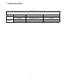
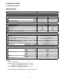
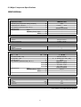
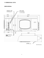
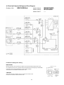
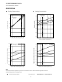
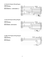
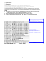
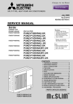
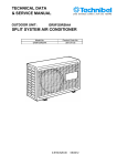
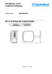
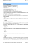
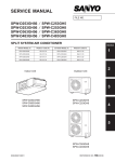
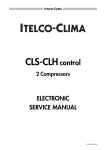
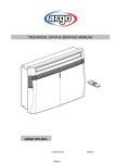
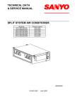
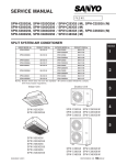
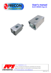
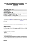
TECHNICAL DATA
& SERVICE MANUAL
GR9FI65R5IAA
.
OUTDOOR UNIT:
TRIAL SPLIT SYSTEM AIR CONDITIONER
Model No.
Product Code No.
GR9FI65R5IAA
.
38.7107.102
0.8180.611.02
09/2012
IMPORTANT!
Please read before installation
This air conditioning system meets strict safety and operating
standards.
For the installer or service person, it is important to install or
service the system so that it operates safely and efficiently.
For safe installation and trouble-free operation, you must:
• Carefully read this instruction booklet before beginning.
• Follow each installation or repair step exactly as shown.
• Observe all local, state and national electrical codes.
• Pay close attention to all warning and caution notices given in
this manual.
•The unit must be supplied with a dedicated electrical line.
• Ground the unit following local electrical codes.
• The Yellow/Green wire cannot be used for any connection
different from the ground connection.
• Connect all wiring tightly. Loose wiring may cause overheating
at connection points and a possible fire hazard.
• Do not allow wiring to touch the refrigerant tubing, compressor,
or any moving parts of the fan.
• Do not use multi-core cable when wiring the power supply and
control lines. Use separate cables for each type of line.
When transporting
Be careful when picking up and moving the indoor and outdoor
units. Get a partner to help, and bend your knees when lifting to
reduce strain on your back. Sharp edges or thin aluminium fins on
the air conditioner can cut your fingers.
WARNING
This symbol refers to a hazard or unsafe practice which can result
in severe personal injury or death.
CAUTION
This symbol refers to a hazard or unsafe practice which can result
in personal injury or product or property damage.
If necessary, get help
These instructions are all you need for most installation sites and
maintenance conditions.
If you require help for a special problem, contact our sale/service
outlet or your certified dealer for additional instructions.
In case of improper installation
The manufacturer shall in no way be responsible for improper
installation or maintenance service, including failure to follow the
instructions in this document.
When installing...
... In a ceiling or wall
Make sure the ceiling/wall is strong enough to hold the unit-weight.
It may be necessary to build a strong wooden or metal frame to
provide added support.
... In a room
Properly insulate any tubing run inside a room to prevent
"sweating", which can cause dripping and water damage to walls
and floors.
... In moist or uneven locations
Use a raised concrete base to provide a solid level foundation for
the outdoor unit.
This prevents damage and abnormal vibrations.
... In area with strong winds
Securely anchor the outdoor unit down with bolts and a metal
frame. Provide a suitable air baffle.
... In a snowy area (for heat pump-type systems)
Install the outdoor unit on a raised platform that is higher than
drifting snow. Provide snow vents.
SPECIAL PRECAUTIONS
• During installation, connect before the refrigerant system and
then the wiring one; proceed in the reverse orden when removing
the units.
WARNING
When wiring
ELECTRICAL SHOCK CAN CAUSE SEVERE
PERSONAL INJURY OR DEATH. ONLY A QUALIFIED,
EXPERIENCED ELECTRICIANS SHOULD ATTEMPT
TO WIRE THIS SYSTEM.
When connecting refrigerant tubing
• Keep all tubing runs as short as possible.
• Use the flare method for connecting tubing.
• Apply refrigerant lubricant to the matching surfaces of the flare
and union tubes before connecting them; screw by hand and
then tighten the nut with a torque wrench for a leak-free
connection.
• Check carefully for leaks before starting the test run.
NOTE:
Depending on the system type, liquid and gas lines may be either
narrow or wide. Therefore, to avoid confusion, the refrigerant
tubing for your particular model is specified as narrow tube for
liquid, wide tube for gas.
• Do not supply
power to the unit until all wiring and tubing are
0.8180.531.00
05/2007
completed or reconnected and checked, to ensure the grounding.
• Highly dangerous electrical voltages are used in this system.
Carefully refer to the wiring diagram and these instructions when
wiring.
Improper connections and inadequate grounding can cause
accidental injury and death.
2
When servicing
• Turn the power OFF at the main power board before opening
the unit to check or repair electrical parts and wiring.
• Keep your fingers and clothing away from any moving parts.
• Clean up the site after the work, remembering to check that no
metal scraps or bits of wiring have been left inside the unit being
serviced.
• Ventilate the room during the installation or testng the refrigeration
system; make sure that, after the installation, no gas leaks are
present, because this could produce toxic gas and dangerous
if in contact with flames or heat-sources.
Table of Contents
Page
1. OPERATING RANGE
4
2. SPECIFICATIONS
5
2-1 Unit Specifications
2-2 Major Component Specifications
2-3 Other Component Specifications
5
6
7
3. DIMENSIONAL DATA
8
4. REFRIGERANT FLOW DIAGRAM
9
4-1 Trial Split System Refrigerant Flow Diagram
4-2 Dual Split System Refrigerant Flow Diagram
4-3 Mono Split System Refrigerant Flow Diagram
5. PERFORMANCE DATA
9
10
11
12
5-1 Performance Charts
12
6. ELECTRICAL DATA
13
6-1 Electrical Characteristics
6-2 Electric Wiring Diagram
6-3 Trial Split System Wiring Diagram
6-4 Dual Split System Wiring Diagram
6-5 Mono Split System Wiring Diagram
13
14
15
15
15
7. FUNCTION
16
7-1 Diagnostic
16
3
1. OPERATING RANGE
GR9FI65R5IAA
.
Cooling
Heating
Temperature
Indoor Air Intake Temp.
Outdoor Air Intake Temp.
Maximum
32°C D.B. / 23°C W.B.
43°C D.B.
Minimum
10°C D.B. / 6°C W.B.
-15°C D.B.
Maximum
27°C D.B.
24°C D.B. / 18°C W.B.
Minimum
5°C D.B.
-15°C D.B.
4
2. SPECIFICATIONS
2-1 Unit Specifications
GR9FI65R5IAA
Power source
220 - 240 V ~ 50 Hz
Voltage rating
230 V
Performance *
Capacity
MPA9FIB0R5I x1 + MTAFIA0R5I x2
kW
BTU/h
m³/h
Liters/h
Air circulation (High)
Moisture removal (High)
V
A
W
%
W/W
A
Features
Fan speed
Compressor
Refrigerant / Amount charged at shipment
Refrigerant control
Power noise level
Hi
Refrigerant tubing connections
Max. allowable tubing length at shipment
Refrigerant
Narrow tube
tube diameter
Wide tube
Package dimensions
Weight
Heating
7,30
24909
600
1,5
-
Cooling
Electrical Rating
Available voltage range
Running amperes
Power input
Power factor
C.O.P.
Compressor locked rotor amperes
Dimensions & Weight
Unit dimensions
Cooling
6,50
22179
g
dB-A
m
mm(in.)
mm(in.)
Height
Width
Depth
Height
Width
Depth
Net
Shipping
mm
mm
mm
mm
mm
mm
kg
kg
m3
Shipping volume
Heating
198 ~ 264
8,90
2000
98
3,25
-
7,50
1690
98
4,32
-
3 (hi755 - me395 - lo258)
Twin Rotary (Hermetic) DC inverter
R410A / 2700
Electronic expansion valve
64
Flare type
see installation instruction
6,35 (1/4)
9,52 (3/8) - 12,7 (1/2)
735
1030
340/400
900
1140
420
64,0
70,0
0,43
DATA SUBJECT TO CHANGE WITHOUT NOTICE
Remarks:
Rating Conditions are:
Cooling: Indoor Air Temperature 27°C D.B. / 19°C W.B.
Outdoor Air Temperature 35°C D.B. / 24°C W.B.
Heating: Indoor Air Temperature 20°C D.B.
Outdoor Air Temperature 7°C D.B. / 6°C W.B.
*
For other INDOOR UNITS' MODELS, please refer to catalogue
5
2-2 Major Component Specifications
GR9FI65R5IAA
Compressor
Type
Compressor model
Nominal input (compressor rating condition)
Compressor oil…Amount
Coil resistance (Ambient temp. 20°C)
Overload relay
Safety devices
Type
Operating Temp. Open
Close
W
cc
Ω
°C
°C
Twin Rotary (Hermetic) DC inverter
TNB220FLHMT
2200
FV50S …… 870
0,64
Software Protection
-
Controller PCB
Part No.
Controls
Control circuit fuse
sac dci ODU
Microprocessor
6,3x32 - 12,5A
Expansion PCB
Part No.
Controls
Control circuit fuse
sac espansion multi dci
-----
Fan & Fan Motor
Type
Q'ty ……. Ø
Fan motor model…Q'ty
No. Of poles…rpm
Nominal output
Coil resistance (Ambient temp. 25 °C )
Safety devices
°C
°C
Propeller
1…. Ø 460
KFC6T-91C5P
6 ... 3 speed (755 - 395 - 258)
65,66
BRN-WHT: 127.3
WHT-VLT: 56.73
VLT-YEL: 15.04
YEL-PNK: 7.235
Thermal Protector
130 °C
-
mm
m2
Aluminium plate fin / Copper tube
2
1,4
0,60
Nr. … mm
W
Ω
Ω
Ω
Ω
Type
Operating temp. Open
Close
Heat Exch. Coil
Coil
Rows
Fin pitch
Face area
Acrylic baked-on enamel finish
External Finish
DATA SUBJECT TO CHANGE WITHOUT NOTICE
6
2-3 Other Component Specifications
GR9FI65R5IAA
.
4-way Valve (20S)
Coil rating
Coil resistance
Electronic Expansion Valve A
Coil rating
Coil resistance / phase
Electronic Expansion Valve B-C
Coil rating
Coil resistance / phase
Defrost Valve
Coil rating
Coil resistance
Ω (at 20°C)
LDK-41 (Coil) V2-410060-300 (Valve)
AC 220/240 V, 50 Hz
1600 ± 5%
Ω (at 20°C)
UKV-U030E (Coil) UKV-18D31 (Valve)
DC 12 V
46 ± 3%
Ω (at 20°C)
CAM-MD12EX(Coil) ZCAM-BD15EX (Valve)
DC 12 V
46 ± 4%
Ω (at 20°C)
FQ-235-RK (Coil) FDF6A-049-RK (Valve)
AC 220/240 V - 50 Hz
1273 ± 10%
kΩ
NTC-THERMISTOR
10 at 25 °C
Thermistor (compressor discharge sensor)
Resistance
kΩ
NTC-THERMISTOR
10 at 25 °C
Thermistor (inlet air sensor)
Resistance
kΩ
NTC-THERMISTOR
10 at 25 °C
Thermistor (wide tube A sensor)
Resistance
kΩ
NTC-THERMISTOR
10 at 25 °C
Thermistor (narrow tube A sensor)
Resistance
kΩ
NTC-THERMISTOR
10 at 25 °C
Thermistor (wide tube B sensor)
Resistance
kΩ
NTC-THERMISTOR
10 at 25 °C
Thermistor (narrow tube B sensor)
Resistance
kΩ
NTC-THERMISTOR
10 at 25 °C
Thermistor (wide tube C sensor)
Resistance
kΩ
NTC-THERMISTOR
10 at 25 °C
kΩ
NTC-THERMISTOR
10 at 25 °C
Thermistor (coil sensor)
Resistance
Thermistor (narrow tube C sensor)
Resistance
Crank case heater
Resistance
Ω (at 20°C)
20W - RESISTANCE
2640 ± 10%
Base heater
Resistance
Ω (at 20°C)
75W - FLEXELEC CSC2
705 ± 10%
DATA SUBJECT TO CHANGE WITHOUT NOTICE
7
3. DIMENSIONAL DATA
GR9FI65R5IAA
.
NARROW TUBE
3x ø.6,35 (1/4")
WIDE TUBE
2x ø.9,52 (3/8")
1x ø.12,7 (1/2")
SERVICE VALVE
TUBE
2x ø.6,35 (1/4")
4 - Ø12
for anchor bolt
dimension [mm]
8
4. REFRIGERANT FLOW DIAGRAM
4-1 Trial Split System Refrigerant Flow Diagram
Outdoor Unit:
GR9FI65R5IAA
Indoor Unit A:
Indoor Unit B:
Indoor Unit C:
Insulation of Refrigerant Tubing
IMPORTANT
Because expansion valve is used in the outdoor unit, both the wide and narrow tubes of this
air conditioner become cold. To prevent heat loss and wet floors due to dripping of condensation,
both tubes must be well insulated with a proper insulation material.
The thickness of the insulation should be a min. 8mm.
CAUTION
After a tube has been insulated, never try to bend it into a narrow curve
because it can cause the tube to break or crack.
9
MPA9FIB0R5I..
MTAFIA0R5I..
MTAFIA0R5I..
4-2 Dual Split System Refrigerant Flow Diagram
Outdoor Unit:
GR9FI65R5IAA
Indoor Unit A:
Indoor Unit B:
Indoor Unit C:
Insulation of Refrigerant Tubing
IMPORTANT
Because expansion valve is used in the outdoor unit, both the wide and narrow tubes of this
air conditioner become cold. To prevent heat loss and wet floors due to dripping of condensation,
both tubes must be well insulated with a proper insulation material.
The thickness of the insulation should be a min. 8mm.
CAUTION
After a tube has been insulated, never try to bend it into a narrow curve
because it can cause the tube to break or crack.
10
MPA9FIB0R5I..
MTAFIA0R5I..
--
4-3 Mono Split System Refrigerant Flow Diagram
Outdoor Unit:
GR9FI65R5IAA
Indoor Unit A:
Indoor Unit B:
Indoor Unit C:
"BRIDGE"
TUBE
Insulation of Refrigerant Tubing
IMPORTANT
Because expansion valve is used in the outdoor unit, both the wide and narrow tubes of this
air conditioner become cold. To prevent heat loss and wet floors due to dripping of condensation,
both tubes must be well insulated with a proper insulation material.
The thickness of the insulation should be a min. 8mm.
CAUTION
After a tube has been insulated, never try to bend it into a narrow curve
because it can cause the tube to break or crack.
11
MPA9FIB0R5I..
---
5. PERFORMANCE DATA
5-1 Performance charts
GR9FI65R5IAA
Cooling Characteristics
Heating Characteristics
10,0
32
Indoor inlet air
D.B. (°C)
9,0
27
Indoor inlet air
D.B. (°C)
25
19
8,0
20
Operating current (A)
Operating current (A)
8,0
6,0
19
27
32
4,0
15
7,0
32
6,0
27
19
2,0
5,0
1
0,0
10
15
20
25
30
35
4,0
40
0
Outdoor inlet air D.B. temperature (°C)
5
7
10
15
20
Outdoor inlet D.B. temperature (°C)
1,20
Indoor inlet air
D.B. (°C)
Indoor inlet air
D.B. (°C)
2,9
25
1,10
High pressure at wide tube service valve Mpa
Low pressure at wide tube service valve MPa
2,7
1,00
32
0,90
27
0,80
19
0,70
0,60
0.8180.531.00
05/2007
0,50
2,5
20
2,3
15
2,1
1,9
1,7
1,5
10
15
20
25
30
35
40
0
Outdoor inlet air D.B. temperature (°C)
5
7
10
15
20
Outdoor inlet air D.B. temperature (°C)
Note
Overload prevention operates to protect the air conditioner when outdoor ambient temperature reaches
extremely high values in heating mode.
Points of Rating condition
Data referred to
12
MPA9FIB0R5I x1 + MTAFIA0R5I x2
6. ELECTRICAL DATA
6-1 Electrical characteristics
Outdoor unit:
GR9FI65R5IAA
COOLING
3 Indoor Unit
Fan Motor
Performance at
Rating conditions
Rating Conditions:
Running Amps.
Power input
A
kW
0,66
0,148
Outdoor unit
Fan Motor + Compressor
230 V - 1 Phase - 50 Hz
8,24
1,852
Complete Unit
8,9
2,000
Indoor Air Temperature 27°C D.B. / 19°C W.B.
Outdoor Air Temperature 35°C D.B. / 24°C W.B.
HEATING
3 Indoor Unit
Performance at
Rating conditions
Rating Conditions:
Running Amps.
Power input
A
kW
0,66
0,148
Outdoor unit
Fan Motor + Compressor
230 V - 1 Phase - 50 Hz
6,84
1,542
Indoor Air Temperature 20°C D.B.
Outdoor Air Temperature 7°C D.B. / 6°C W.B.
NOTE: Data referred to 3 indoor unit, MPA9FIB0R5I x1 + MTAFIA0R5I x2
For other indoor unit models there could be some differences.
13
Complete Unit
7,5
1,690
6-2 Electric Wiring Diagram
GR9FI65R5IAA
14
6-3 Trial Split System Wiring Diagram
Outdoor unit:
GR9FI65R5IAA
Indoor unit:
MPA9FIB0R5I x1 + MTAFIA0R5I x2
6-4 Dual Split System Wiring Diagram
Outdoor unit:
GR9FI65R5IAA
Indoor unit:
MPA9FIB0R5I + MTAFIA0R5I
6-5 Mono Split System Wiring Diagram
Outdoor unit:
GR9FI65R5IAA
Indoor unit:
MPA9FIB0R5I
15
7. FUNCTION
7-1 Diagnostic
With this feature is possible to have a visual signal that a trouble is occurring.
This mode is always active and the signalling is made through the display board LEDS .
In case of no troubles the LEDS status follows its normal function.
The detected troubles are showed to the user/technician using the 3 (5) leds of the indoor unit receiver
and the 5 leds on the outdoor pcb. For each fault there are different effects upon the operation of the A/C:
NOTES
The troubles are showed according to a priority list that is in case of more than one trouble present,
is always showed, at first, the one with the highest priority (3 2 1 etc).
Sensor damaged means a situation where sensor is short-circuited or opened.
In case of damaged sensors, the system (CM, FMO, FMI etc), if in OFF state, does not start.
system does not operate. To restart the system,
power re-setting (off-on) is required
note: before restoring power, adjust the dip-switch
status on idu according to the connection pipes
system does not operate.
as soon as fault is cleared, the system
automatically restart after 3 min
during this time, the signalling is showed
EFFECTS
16
R.D. 28 Reyrieux BP 131 - 01601 Trévoux CEDEX France
Tél. 04.74.00.92.92 - Fax 04.74.00.42.00
R.C.S. Bourg-en-Bresse B 759 200 728