1
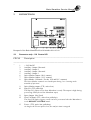
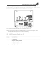
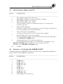
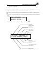
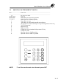
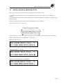
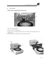
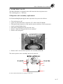
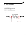
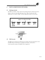
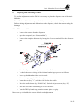
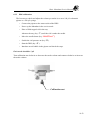
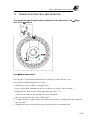
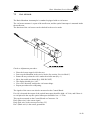
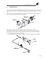
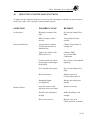
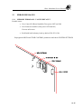
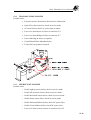
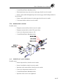
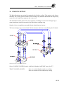
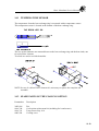
BASIC MARATHON SERVICE MANUAL
Version 1.0, September 1995
Part no. 0060.100
P.O. BOX 388,
7800 AJ EMMEN,
THE NETHERLANDS
Phone: (31) 591 - 631700
Fax: (31) 591 – 630035
E-mail: [email protected]
Basic Marathon Service Manual
Version 1.0
Basic Marathon Service Manual
Version 1.0
TABLE OF CONTENTS
Page:
IMPORTANT NOTICE
SPECIFICATIONS
1
PROGRAMMING CHART
1.1
2
CONNECTIONS
2.1
2.1
2.2
2.3
2.4
2.5
2.1
2.3
2.4
2.4
2.5
3
4
5
6
7
CONTROL I/O STRIP
AUX 1 - 2
CONTROL I/O
VIAL NUMBER OUTPUT
RS 232 SERIAL INTERFACE
SERVICE MODE
3.1
3.1
3.2
HOW TO USE THE SERVICE KEYS
DISASSEMBLING
4.1
4.1
4.2
4.3
4.1
4.2
4.2
REARPANEL
TOP COVER
TRAY COVER
INJECTION VALVE
5.1
5.1
5.2
5.3
5.1
5.2
5.2
INJECTION VALVE ASSEMBLY REPLACEMENT
INJECTION VALVE REPLACEMENT
PORT CONNECTIONS OF THE INJECTION VALVE
DIGITAL DISPENSER SYSTEM
6.1
6.1
6.2
6.3
6.1
6.1
6.2
6.2
6.3
6.4
WORKING PRINCIPLE
DDS-CASSETTE
ADJUSTING AND CALIBRATING THE DDS
6.3.1 DDS CASSETTE BLOCK
6.3.2 ADJUSTING THE DDS CASSETTE BLOCK
6.3.3 DDS CALIBRATION
NEEDLE
7.1
7.1
7.2
7.3
7.2
7.3
7.4
NEEDLE HEIGHT ADJUSTMENT
NEEDLE PENETRATION ADJUSTMENT
VIAL SENSOR
8
COMPRESSOR
8.1
9
SAMPLE FLOW PATH
9.1
10
INJECTION SYSTEM MALFUNCTION
10.1
11
BASIC MARATHON TEST PROCEDURE
11.1
11.1
EXAMPLE OF TESTCHROMATOGRAM
11.2
12
FIRMWARE
12.1
13
ERROR MESSAGES
13.1
13.1
13.2
13.3
13.1
13.2
13.2
MEMORY ERROR
TRAY ROTATION FAILURE
NEEDLE UNIT FAILURE
Basic Marathon Service Manual
Version 1.0
13.4
13.5
DISPENSER FAILURE
INJECTION VALVE ERROR
13.3
13.3
14
COOLING OPTION
14.1
TEMPERATURE SENSOR
14.2
SPARE PARTS OF THE COOLING OPTION
14.1
14.2
14.2
15
SPARE PARTS NOT SHOWN IN DRAWINGS
15.1
APPENDIX A CHEMICAL RESITANCE OF KALREZ
DRAWINGS
INJECTOR VALVE ASSY
DIGITAL DISPENSER
NEEDLE ARM ASSY 816
KEYBOARDHOUSE BASIC
TRAY-NEEDLE SUB ASSY (SET OF 3 PAGES)
DISPENSER / VALVE FRAME 816
MAINS INLET
REARPANEL 816
BASIC CABINET
71.0816.301
71.0816.302
71.0816.308
71.0816.320
71.0816.400
71.0816.401
71.0816.410
71.0816.601
71.0816.900
SCHEMATICS
WIRING DIAGRAM BASIC Till serial number 0816.4.3.60
WIRING DIAGRAM BASIC From serial number 0816.5.1.01
CONTROL I/O BOARD BASIC Till serial number 0816.4.3.60
CONTROL I/O BOARD BASIC From serial number 0816.5.1.01
31.0816.900 Revision:1
31.0816.900 Revision:4
31.0816.601 Revision:1
31.0816.601 Revision:3
Basic Marathon Service Manual
Version 1.0
1 PROGRAMMING CHART
Basic Marathon Service Manual
Version 1.0
2
CONNECTIONS
Rearpanel of the Basic Marathon till serial number 0816.4.3.60
2.1
Connector strip J 16 Control I/O
_____________________________________________________________________________
PIN N0
Description
_________________________________________________________________
_
1
2
3
4
5
6
7
8
+ 24 Volts DC
Auxiliary Output 2 Inverted
Auxiliary Output 2
Auxiliary Output 1 Inverted
Auxiliary Output 1
Inject Marker Output (N.O. contact)
Inject Marker Output ( N.C. contact)
Inject Marker Common ( For the N.O and N.C. contacts)
The Inject Marker contacts are closed/open during 1 sec. starting at the
moment of injection !
9
10
Inject Marker output (TTL, active low)
Stop I/O (TTL pulled up)
The Stop I/O output is low when Marathon is ready. The output is high during
processing (When forced low Marathon stops)
11
12
Spare Output (Not Used)
Next Vial Input (TTL, active low, pulled up)
The Next Vial Input triggers a next vial to be processed when the Marathon is
in the REMOTE CONTROL mode.
13
Freeze (TTL, active low, pulled up)
As long as the Freeze input is low, the analysis time is stopped.
Basic Marathon Service Manual
Version 1.0
14
Next Injection input (TTL, active low, pulled up)
The Next Injection Input triggers a next injection when Marathon is in the
REMOTE CONTROL mode. Can be used as a start input (also when
Marathon is not in REMOTE CONTROL mode)
15
16
NOTE:
Ground
Ground
Î The auxiliaries are open collector outputs, max. 250 mA, 28 Volts.
Î The duration of input 10,12 and 14 must be at least 20 mSec.
TTL Input
TTL Output
Contact closures outputs
Basic Marathon Service Manual
Version 1.0
In order to meet IEC 1010 regulations connector strip J16 is divided into two sub D-connectors
(J16 and J24) The pin description from Serial Number 816 5.1.01 is now:
New rearpanel of the Basic Marathon from serial number 0816.5.1.01
NOTE: A new control I/O Board can still be placed in a previous model rearpanel, only a
screening label must be placed over the previous screening.
2.2
J16 D-Connector (Female) Aux.1-2
_____________________________________________________________________________
PIN NO
DESCRIPTION
_____________________________________________________________________________
1
2
3
4
5
6-9
+ 24 Volts DC
Auxiliary Output 2 Inverted
Auxiliary Output 2
Auxiliary Output 1 Inverted
Auxiliary Output 1
Ground
Basic Marathon Service Manual
Version 1.0
2.3
J24 D-Connector (Male) Control I/O
_____________________________________________________________________________
PIN NO.
DESCRIPTION
_____________________________________________________________________________
1
2
3
4
Inject Marker output (TTL, active low)
Inject Marker Common ( For the N.O and N.C. contacts)
Inject Marker Output ( N.C. contact)
Inject Marker Output (N.O. contact)
The Inject Marker contacts are closed/open during 1 sec. starting at the
moment of injection !
5
Stop I/O (TTL pulled up)
The Stop I/O output is low when Marathon is ready. The output is high during
processing (When forced low Marathon stops)
6
Freeze (TTL, active low, pulled up)
As long as the Freeze input is low, the analysis time is stopped.
7
Next Vial Input (TTL, active low, pulled up)
The Next Vial Input triggers a next vial to be processed when the Marathon is
in the REMOTE CONTROL mode.
8
Next Injection input (TTL, active low, pulled up)
The Next Injection Input triggers a next injection when Marathon is in the
REMOTE CONTROL mode. Can be used as a start input (also when
Marathon is not in REMOTE CONTROL mode)
9-15
Ground
2.4
Connector J 14 (Female) VIAL NUMBER OUTPUT
8-bit BCD coded VIAL NUMBER OUTPUT (True logic, TTL) representing vial numbers 196; active when corresponding vial is processed.
_____________________________________________________________________________
PIN NO
DESCRIPTION
_____________________________________________________________________________
1
2
3
4
8
9
10
11
12
15
Bit D0 units 1
Bit D2 units 4
Bit D4 units x 10
Bit D6 units x 40
Ground
Bit D1 units 2
Bit D3 units 8
Bit D5 units x 20
Bit D7 units x 80
Inject Marker (TTL, active low)
Basic Marathon Service Manual
Version 1.0
Examples of BCD VIAL NUMBER OUTPUT
D7
D6
D5
D4
D3
D2
D1
D0
80
40
20
10
8
4
2
1
OUTPUT
1
0
0
1
0
1
1
0
96
OUTPUT
0
1
0
1
1
0
0
1
59
OUTPUT
0
0
0
1
0
0
0
0
10
BCD
2.5
VIAL
NUMBER
Connector J12 RS 232 Serial Interface
The Basic Marathon can be controlled by a PC using the RS 232 interface and the
“SPARKLINK” Application software from Spark Holland (optional). Refer to the
“SPARKLINK” manual (part no.: 0060.101) for operating instructions
J12 D-Connector (Female) Serial Interface
_____________________________________________________________________________
PIN NO
DESCRIPTION
_____________________________________________________________________________
1
2
3
4
5
7
20
Shield
Tx
Rx
RTS
CTS
GND
DTR
Basic Marathon Service Manual
Version 1.0
3
SERVICE MODE
The software of the Basic Marathon is provided with a service mode. In the service mode it is
possible to control all the outputs and mechanical movements.
Since the service mode is only to be used by an qualified service engineer, it is protected by a
code.
To access the service mode; turn off the power and switch the instrument on while holding the
CL” key down. The display will show:
“
SERVICE MODE -- °C
PRESS F0 TO EXIT
To access the control mode enter the service code
73
The Marathon will now display the following screen.
Inj Valve in
INJECT position
Inj.Valve in
LOAD position
TRAY Sensor
VIAL Detected
Temp of the
Coolsensor
INJ LOAD TRAY VIAL --°C
EV ODD HOR DWN DDS S
Serial Test Code
DDS Sensor
Stop Sensor Horizontal
Movement
Sensor Needle Arm Outer
Ring:Odd Vials
Sensor Needle Arm Inner
Ring:Even Vials
Basic Marathon Service Manual
Version 1.0
3.1
HOW TO USE THE SERVICE KEYS
_____________________________________________________________________________
KEY
FUNCTION
_____________________________________________________________________________
CL
Start the service mode
START/STOP
Needle up
HOLD/CONT
Needle down (only in correct tray position)
PROG/END
Needle left (only in needle up position)
À
Needle right (only in needle up position)
1
2
3
0
4
5
9
6
7
8
NOTE:
Tray makes one step
Tray makes one step and the needle moves down.
The needle moves down and up in every second position of the tray
To STOP function 3
Dispenser ON
Dispenser OFF
Compressor ON (Overhead vial pressure 0.5 bar)
Compressor OFF
Injection valve in LOAD position.
Injection valve in INJECT position
To exit the service mode turn the main power OFF
10.12
Basic Marathon Service Manual
Version 1.0
3.2
SERIAL MODE HARDWARE TEST
In the service mode it is also possible to check the proper function of the serial port.
To check the communication port a short circuit should be made between pin number 2 and 3 on the RS 232
connector.
The autosampler will sent out data via the TXD and receives the same data back via the RXD, it compare the send
and received data.
Remove all remote connectors and power up the autosampler in the service mode.
The layout of the connector is as follows:
25 pins D-connector Female
Pressing the “CL” key, in the service mode, will result in a B followed by an ! on the right corner of the display.
When the communication is not established, a ? is displayed.
Initial service mode screen:
INJ LOAD TRAY VIAL --°C
EV ODD HOR DWN DDS S
After pressing the “CL” key:
INJ LOAD TRAY VIAL --°C
EV ODD HOR DWN DDS B
When the communication is established:
INJ LOAD TRAY VIAL --°C
EV ODD HOR DWN DDS !
10.13
Basic Marathon Service Manual
Version 1.0
4
DISASSEMBLING
4.1
REARPANEL
To open the rear panel proceed as follows:
• Remove the two screw marked A
• Remove the keyboard/display flatcable from the control I/O Board.
A
A
The picture below shows the Basic Marathon with open rear side
Injection
Valve Motor
Air Pressure
Regulator
Eprom
10.14
Basic Marathon Service Manual
Version 1.0
4.2
TOP COVER
• Remove the cassette block and his screw
B
B
B
B
B
• Open the keyboard/display.
• Remove all the screws Marked B
• Lift the top cover and Keyboard display house up and place them behind the Basic. See
figure below.
In this position the Basic Marathon is still complete operational.
B
B
B
B
10.15
Basic Marathon Service Manual
Version 1.0
4.3
TRAY COVER
For disassembling the Tray cover it is necessary to remove the following items:
• Remove the vial stripper/injection valve drain (located under the injection valve).
• Remove the 4 tray segments and the white tray support screw; located inside the leaking bath
under the needle arm (only in non-cool versions).
• Remove the 4 screws marked C (two on each side) and lift the tray cover up at the front.
C
C
C
C
NOTE: Make sure the drain connection is made after reassembling of the tray cover.
Injection
Valve
Assembly
Compressor
Basic Marathon with removed topcover and traycover.
10.16
Basic Marathon Service Manual
Version 1.0
5 INJECTION VALVE
The Basic Marathon is equipped with a full electrical driven injection valve.
The switching time is < 100 msec.
5.1Injection valve assembly replacement
For Disassembling/Replacing the entire injection valve proceed as follows:
•
•
•
•
•
•
•
Turn mains power off
Open rear panel and remove connector J15 of the control I/O Board.
Disconnect both connectors of the optical sensors (mark one of the connectors).
Open keyboard/display house
Disconnect plumbing from the injection valve
Remove from the front panel the screws marked C
Remove the front panel
C
C
C
C
C
•
Remove the 2 screws of the injection valve assembly marked B
The entire injection valve assembly can now be removed
For more detailed information see drawing 71.0816.301
10.17
Basic Marathon Service Manual
Version 1.0
5.2
Injection valve replacement
For Disassembling/Replacing the injection valve proceeds as follows:
•
•
•
•
•
•
•
Turn mains power off
Open keyboard/display
Disconnect plumbing from the injection valve
Remove the front panel
Remove the 4 screws marked A
Remove the injection valve and mounting plate
Remove the valve lever from the injection valve
The injection valve can now be replaced.
For more detailed information see drawing: 71.0816.301
10.18
Basic Marathon Service Manual
Version 1.0
Notes for reassembling:
• Make sure the detector strap is in-line with the optical sensors.
• Place the injection valve manually in the inject position (detector strap is inside of the inject
sensor.
• Turn the motor leaver in the position with the white bearing down (Out of the leaver
springs!)
• Switch the injection valve manually to check if there are any mechanical obstructions.
5.3
Port Connections of the Injection Valve
Port Number Description
1
2
3
4
5
6
Loop
Needle → Valve tubing
Dispenser tubing
Loop
HPLC Pump
Column
10.19
Basic Marathon Service Manual
Version 1.0
6
6.1
DIGITAL DISPENSER SYSTEM (DDS)
Working principle:
The DDS is a miniature “finger” pump. The operating principle is shown in fig. below.
Fingers 1 and 3 act as inlet and outlet pinch valves. Finger 2 provides the fluid
displacement. The stroke of finger 2 is factory adjusted to provide 2 µL per stroke.
6.2
DDS Cassette
The DDS cassette is built up out different types of tubing. The most important one is the
KALREZ tubing. This black piece of tubing is protected by a silicon sleeve.
For the chemical resistance of KALREZ refer to appendix A.
10.20
Basic Marathon Service Manual
Version 1.0
6.3
Adjusting and calibrating the DDS.
To perform adjustments on the DDS it is necessary to place the dispenser out of the Basic
Marathon.
For calibration of the volume per stroke it is not necessary to remove the dispenser.
Before making adjustments and calibrations on the dispenser, check the cassette tubing for
damages
6.3.1 DDS cassette block.
•
Remove the cassette from the dispenser.
•
Open the rear panel (see “Disassembling”)
•
Remove the complete dispenser by loosing the 2 screws marked D for the dispenser
plate
•
Place the dispenser on the top cover and reinstall the cassette.
•
To check the correct closing of the inlet and outlet finger proceed as follows:
•
Power up the Marathon in the service mode
•
Place an empty capped vial in the tray.
•
Rotate the tray (key ”1”) until the vial is below the needle.
•
Move the needle down (key “Hold/Cont”). Switch vial pressure on (key “9”).
•
Place the end of the waste tubing in a vial with water.
•
Turn the DDS by hand using rotation counter plate as a grip.
If there are any air bubbles the cassette block needs adjustment.
10.21
Basic Marathon Service Manual
Version 1.0
6.3.2 Adjusting the DDS cassette block:
•
Set the Marathon up as described in the previous section.
•
Loosen the two marked screws E
•
Press the cassette carefully down until the air flow in the waste outlet stops
Cassette block
E
E
•
Tighten up the screws and check if it is still possible to turn the disc clockwise
without any obstructions.
•
Check for correct closure on every position of the disc.
10.22
Basic Marathon Service Manual
Version 1.0
6.3.3
DDS calibration:
The best way to check and adjust the volume per stroke is to use a 100 µL volumetric
pipette or a 100 µL syringe.
•
Connect the pipette to the waste outlet of the DDS.
•
Power up the Marathon in the service mode
•
Place a filled capped vial in the tray.
Advance the tray (key “1”) until the vial is under the needle.
•
Move the needle down (key “Hold/Cont.”).
•
Switch the vial pressure on (key “9”).
•
Start the DDS (key “4”).
•
Introduce an air bubble in the pipette and check the steps.
Each stroke should be 2 µL
Turn calibration nut clockwise to decrease the stroke volume and counter-clockwise to increase
the stroke volume
Calibration nut
10.23
Basic Marathon Service Manual
Version 1.0
7
NEEDLE
Needle connection:
* To achieve a low dead volume connection between needle and tubing, make sure that
the end of the tubing is straight.
Partnumber
Description
0042.565
Nut
0042.793
Needle body
0810.718
Air needle (including seal)
0810.720
Set of 3 sample needles (including slice of silicone tubing)
2049.560
Teflon ferrule
3796.032
Rheodyne reflex ferrule
3796.033
Rheodyne reflex nut
7100.703
Teflon tubing OD=1.6mm / ID=0.25mm
7.1
NEEDLE HEIGHT ADJUSTMENT
10.24
Basic Marathon Service Manual
Version 1.0
•
•
•
•
•
Power up the Marathon in the Service Mode
Place an uncapped vial in the tray
Advance the tray (key “1”) until the vial is under the needle.
Loosen the needle height adjustment screw on the left side of the needle arm, and set the
needle body as high as possible
Tighten the needle height adjustment screw.
•
•
•
•
•
Move the needle arm down (key “Hold/Cont”).
Loosen the needle height adjustment screw
Lift the needle body until the tip of the needle is about 1 mm above the bottom of the vial.
Tighten the needle height adjustment screw.
Leave the Service Mode(Power off).
NOTE: Make sure to use the same type of vials, that is normally used in the lab.
10.25
Basic Marathon Service Manual
Version 1.0
7.2
NEEDLE PENETRATION ADJUSTMENTS:
The needle penetration point can be adjusted in two directions. Left ↔ Right
and Front ↑↓to Back
Left ↔ Right adjustment
For left right “Y”penetration adjustment it is necessary to remove the top cover.
(See section:”Dissasembling the Top Cover”)
• fill the tray’s with a couple of uncapped vials.
• Power up the Basic Marathon in the service mode (see section:”Service Mode”)
• Rotate the tray until, a vial is under the needle arm. (key: ”1”).
(The tray will make on step and stop at a correct position)
• Move the needle arm down (Key:“Hold/Cont”).
• To adjust the left ↔ right position, loosen the screws marked Y and position the needle into
the vial centre.
• Tighten the screws and check in the next vials the correct penetration point.
10.26
Basic Marathon Service Manual
Front ↑↓to Back
Version 1.0
For Front ↑↓to Back “X”penetration adjustment it is necessary to remove the following parts:
- Tray’s
- Tray disc
- Tray support screw (white plastic; positioned under the needle arm)
- Tray cover
Replace the tray disc and tray’s
Adjustments in front to back position can be done by changing the stop position of the tray. This
stop position is fixed by an optical interrupter which is mounted on a aluminium plate. This
place can rotate around the spindle foot of the tray and is held in place with screw marked X
• Place a couple of empty decapped vials in the tray’s
• Power up the Basic Marathon in the service mode
• Push key “3” The needle moves down and up in every second position of the tray.
• Turning screw marked X counter clockwise will resulting in an earlier stop position of the
tray under the needle arm.
10.27
Basic Marathon Service Manual
Version 1.0
7.3
VIAL SENSOR
The Basic Marathon Autosampler is standard equipped with an vial sensor.
The vial sensor actuator is a part of the needle arm, and the optical interrupter is mounted inside
the needle arm.
The function of the vial sensor can be checked in the service mode
Check or Adjustment procedure:
•
•
•
•
•
•
•
Place the lowest capped vial in the tray
Power up the Marathon in the service mode (See section “Service Mode”)
Rotate the tray so that the vial is under the needle arm.(Key: 1)
Move the needle arm down (Key: HOLD/CONT)
The display should give:“vial”
If no vial is detected; readjust the vial sensor hinge.
Repeat procedure after readjusting.
The signals of the sensor can also be measured on the Control Board.
If a vial is detected the output of the optical interrupter should be high: >4 Volts, and if there is
no vial placed in the tray the optical interrupter should be low: <1 Volts.
This can be measured on the Control Board on Connector J4.
Pin 9 (Blue wire) is the sensor signal
Pin 8 (Red wire) is the sensor power line (5V)
Pin 7 (Black wire) is the sensor ground line
10.28
Basic Marathon Service Manual
Version 1.0
8
COMPRESSOR
The compressor of the Basic Marathon takes care for the overhead vial pressure of 0.5 Bar for a
improved injection system. The timebased loopfilling mode needs also the compressor to fill the
loop.
The compressor is a solid state membrane type and delivers a pressure from approximately 1.5
Bar, and is located under the injection valve assembly.
The pressure form the compressor is reduced via an pressure regulator to 0.5 Bar
The headspace pressure of the vial should be 0.5 Bar ±20% and can be readjusted with the
pressure regulator. The pressure can be measured in an empty capped vial; the pumptubing
cassette should be closed, with an pressure gauge.
For some applications it is necessary to change the pressure (very high viscosity samples).
10.29
Basic Marathon Service Manual
Version 1.0
10
INJECTION SYSTEM MALFUNCTIONS
To make sure the analytical problem is caused by the Autosampler, and the rest of your system
works fine, make a few injections with an manual injector.
SYMPTOM
POSSIBLE CAUSE
REMEDY
No Injection
Blockage in sample flow
path.
See section Sample Flow
Path.
HPLC pump not on/no
solvent.
Turn pump on/check
solvent.
Loopvolume in settings
list (F9) not the same as
installed loop.
Change Loopvolume in
settings list.
Volume per stroke of the
DDS not correct
Calibrate DDS
See section DDS
Calibration.
Cassette block not closed
by the inlet or outletfinger
of the DDS
See section Cassette Block
adjusting.
No overhead vial pressure
See section Sample Flow
Path
Rotor Seal defect
Replace rotor seal
(Check Stator surface)
Handtight fittings
overtightened
Replace the tubing and
ferrules
Loop not correct in the
injection valve ports fitted
Install a new loop.
Needle/Valve tubing not
straight
Make the tubing’s end
straight.
Rotor seal worn-out
Replace rotor seal.
Check stator for scratches.
Bad reproducibility
Memory Effect
10.30
Basic Marathon Service Manual
Version 1.0
10.31
Basic Marathon Service Manual
Version 1.0
11
BASIC MARATHON TEST PROCEDURE
The Basic Marathon is factory tested for reproducibility and carry over according to the
following test procedure.
The conditions of the analytical system are as follows:
Basic Marathon settings
_____________________________________________________________________________
SYSTEM SETTINGS
RUN PARAMETERS
LOOPVOLUME
:
20µl
FIRST VIAL
:
1
SAMPLE VOLUME
:
STD
LAST VIAL
:
7
FLUSH
:
VOLUME
NO.OF INJ/VIAL
:
3
NEEDLE WASH
:
NO
PREFLUSH
:
30µl
AUXILIARIES
:
NO
ANALYSE TIME
:
1:00 min.
SECOND OVEN TEMP
:
NO
_____________________________________________________________________________
Analytical Parameters
_____________________________________________________________________________
FLOW
:
1.5 ml/min.
PUMP
ELUENT
:
distilled water
DETECTOR WAVELENGTH
:
254 nm
SAMPLE
:
Uracil in distilled water (50 PPM)
_____________________________________________________________________________
Vials 1,4-7 filled with Uracil sample (50 PPM)
Vials 2 and 3 filled with distilled water (ELUENT)
NOTE: Some pumps require a backpressure of approximately 20 bar (250 psi) in order to supply
a constant flow. In those cases an extra capillary as restriction needs to be placed between the
pump and the injection valve.
11.32
Basic Marathon Service Manual
Version 1.0
0.05
0.06
11.1 EXAMPLE OF TESTCHROMATOGRAM
0.04
0.03
Absorbtion
0.02
0.01
0
0
4
8
12
16
20
24
28
Time (min)
Above is an test chromatogram example printed. From the integration results the Relative
Standard Deviation (RSD.....%) can be calculated.
The necessary formula’s are printed below:
Peak area =
σ n −1 =
∑ Peak area
n
∑ ( Peak area
RSD% =
− Peak area
n −1
)
2
σ n −1
× 100%
Peak area
Calculating the RSD% from the example
integration results will give a RSD% of
0.36%
Peak
Number
--------1
2
3
4
5
6
7
8
9
10
11
12
13
14
15
Retention
Time
-------------0.877
2.181
3.480
13.363
14.665
15.964
17.513
18.815
20.114
21.680
22.693
24.281
25.831
27.129
28.430
Integration results
Peak
Area
------------------14.57611
14.65836
14.71600
14.59072
14.61937
14.62571
14.59504
14.65542
14.67614
14.58954
14.64998
14.49563
14.57137
14.58835
14.62109
11.33
Basic Marathon Service Manual
Version 1.0
12
FIRMWARE
The firmware of the Basic Marathon is programmed in an EPROM.
For firmware replacement proceeds as follows:
• Make a notice of the system settings and run parameters
• Turn main power off
• Open the rear panel (See section disassembling rear panel)
•
•
•
Replace the EPROM (U7 located on the top of the control I/O Board)
Close the rearpanel and reassemble the screws.
Check and Reprogram the system settings and run parameters.
CAUTION: The EPROM is highly sensitive for Static discharges.
11.34
Basic Marathon Service Manual
Version 1.0
13
ERROR MESSAGES
13.1 MEMORY ERROR ALL VALUES DEFAULT
Possible cause:
•
New Control I/O Board installed (Turn power OFF and ON)
•
New firmware installed (Turn power OFF and ON)
If errors still occurs:
•
RAM with built in battery back up defect (P/N:2510.210)
Reprogram all RUN and TEMP.CONTROL parameters and check SYSTEM SETTINGS
11.35
Basic Marathon Service Manual
Version 1.0
13.2 TRAY ROTATION FAILURE
Possible cause:
•
Tray movement is obstructed; check/remove obstruction.
•
Optical Tray Sensor defect; check in service mode
•
AC motor defect; check AC power lines to motor.
•
Loose wire from motor or sensor to connector J11
•
Loose wire from Bridge rectifier to connector J17
•
Loose soldering on motor or capacitor
•
Control Board Basic Marathon defect
•
Tooth wheel on gearbox loosened
13.3 NEEDLE UNIT FAILURE
Possible cause
•
Needle right up sensor defect; check in service mode
•
Needle left up sensor defect; check in service mode
•
Needle horizontal sensor defect; check in service mode
•
Needle down sensor defect; check in service mode
•
Needle Horizontal Motor defect; check DC power lines
•
Needle Vertical Motor defect; check DC power lines
•
Loose wire from sensors /motors to connector J4 or J9
11.36
Basic Marathon Service Manual
Version 1.0
•
Control Board Basic Marathon defect
•
Horizontal motor stop vane not in sensor gap; check in service mode
Sensor vane needle left/right & up not in sensor gap; check both positions in
service mode
•
•
Sensor vane needle down not in sensor gap; check in service mode
•
Vial sensor defect; check in service mode
13.4 DISPENSER FAILURE
Possible cause:
•
Dispenser sensor defect; check in service mode
•
Dispenser motor defect; check DC power lines
•
Loose wire from motor/sensor to J10
•
Control Board Basic Marathon defect
13.5 INJECTION VALVE ERROR
Possible cause
•
Sensor Inject defect; check in service mode
•
Sensor Load defect; check in service mode
•
Injection valve motor defect; check in service mode
•
Loose wire from motor/sensors to J15
•
Control Board Basic Marathon defect
•
Injection valve screws over tightened
11.37
Basic Marathon Service Manual
Version 1.0
14 COOLING OPTION
The Basic Marathon can optional be equipped with a Peltier cooling. This option is only factory
installed. The cooling option includes a heat exchange ring mounted underneath the sample tray,
a special set of sample tray segments and a tray cover
The aluminium bottom plates of the tray segments are sliding over the heat exchange ring to
ensure maximum contact between the tray and the heat exchange ring.
Sample vials are completely surrounded by the aluminium tray inserts.
The heat exchange ring is cooled with 2 Peltier elements which are controlled by the I/O board.
NOTE: See section 14.2 for available spare parts
Select COOLING CONTROL mode, with Basic Marathon in READY status, key F,7.
TRAY COOLING (ON/OFF);
Press 1 to switch ON the sample tray cooling
Press 0 to switch OFF the sample tray cooling
11.38
Basic Marathon Service Manual
Version 1.0
14.1 TEMPERATURE SENSOR
The temperature from the heat exchange ring is measured with a temperature sensor.
This temperature sensor is located at the bottom of the heat exchange ring.
The two peltier elements are mounted between the heat exchange ring and the heat sinks, one
for each peltier element.
Two fans are used to cool the heatsinks.
.
NOTE: In case of a defect Peltier element it is necessary to replace the complete sub
assemble.
14.2 SPARE PARTS OF THE COOLING OPTION
Partnumber
Description
2682.006
0816.740
0816.741
0043.588
Fan
Cool option replacement kit (including fan’s and sensor)
Temp sensor assy. 816
Cooling cover
11.39
Basic Marathon Service Manual
Version 1.0
15
SPARE PARTS NOT SHOWN IN DRAWINGS
Part Number
Description
0810.329
0810.327
PUMPTUBING CASSETTE
SERUM PUMPTUBING CASSETTE
0810.718
0810.720
0810.711
0810.712
2997.844
AIR NEEDLE (INCLUDING SEAL)
INJ. NEEDLE PCK/3
SERUM AIR NEEDLE (INCLUDING SEAL)
SERUM INJ. NEEDLE PCK/3
TEFLON COATED LONG LIFE NEEDLE PCK/1
2002.223
2002.230
2002.242
RHEODYNE 7010-122 INJECTION VALVE
RHEODYNE 9010 PEEK INJECTION VALVE
VALCO 22-2006 SPHM INJECTION VALVE
3796.004
3796.050
3796.005
RHEODYNE 7010 ROTOR SEAL
RHEODYNE 7010 TEFZEL ROTOR SEAL
RHEODYNE 7010 STATOR
3796.040
3796.041
3796.042
RHEODYNE 9010 ROTOR SEAL
RHEODYNE 9010 STATOR
RHEODYNE 9010 STATOR FACE ASSY.
3796.043
3796.044
VALCO 22-2006 ROTOR SEAL
VALCO 22-2006 STATOR
3796.032
3796.033
RHEODYNE ‘RHEFLEX’ FERRULE
RHEODYNE ‘RHEFLEX’ NUT
3796.020
3796.021
VALCO FERRULE 1/16”
VALCO NUT 1/16”
3796.035
3796.009
3796.010
3796.011
3796.012
3796.013
3796.014
3796.015
RHEODYNE 5µL LOOP
RHEODYNE 10µL LOOP
RHEODYNE 20µL LOOP
RHEODYNE 50µL LOOP
RHEODYNE 100µl LOOP
RHEODYNE 200µl LOOP
RHEODYNE 500µL LOOP
RHEODYNE 1000µL LOOP
3796.076
3796.016
RHEODYNE 20µL PEEK LOOP
RHEODYNE 100µL PEEK LOOP
3796.046
3796.029
3796.030
3796.031
VALCO 5µL LOOP
VALCO 20µL LOOP
VALCO 200µL LOOP
VALCO 500µL LOOP
11.40


![TSQ Series Getting Started Guide Version C [FR]](http://vs1.manualzilla.com/store/data/006357565_1-ae930521dae4517a45cdbc191dde2ba3-150x150.png)