1
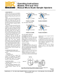
®
Operating Instructions
Type 90 and Type 3000 Switching Valves
1.0 DESCRIPTION
Type 90 and Type 3000 valves are manual
switching valves containing six or seven
ports for a wide range of applications. Type
90 ports accept 1/16" fittings. Type 3000
ports accept 1/8" fittings and are for
preparative scale applications. All Type 90
valves, Models 3000, and 3030 are PEEK
versions, while Models 3000-038 and 3030038 are stainless steel versions. Model 9010
contains a position sensing switch.
Model 9010 can be used as a manual
sample injector with two-positions. A sample
loop attached at Port 1 and Port 4 comes
standard. When the sample loop is
repositioned to Port 1 and Port 5, Model
9010 can be used in a 4-Way configuration.
Removing the sample loop completely
makes Model 9010 into a switching valve.
Model 3000 or 3000-038 can also be used
as a 4-Way valve (two-position) by
connecting a loop to Port 1 and Port 5.
Models 9030, 3030, and 3030-038 are
Double 3-Way valves (two-position) and
Model 9060 is a Six-Position valve.
Figure 1 shows the flow diagrams of Type
90 and Type 3000 switching valves. The
circles represent the ports in the valve stator.
The dark grooves represent the connecting
passages in the rotor seal. See Figure 3 for
the flow diagram of Model 9010 as an
injector.
2.0 SUPPLIED WITH THE VALVE
Supplied in a separate bag are RheFlex®
Fittings sets for all ports and the following
items. Model 9010 also includes a 20 µL
sample loop in a separate bag.
• Hex Keys
• Mounting Screws
• Luer Tube (Model 9010 only)
3.0 SPECIFICATIONS
• Maximum Operating Pressure: Models
3000 and 3030 - 28 MPa (276 bar, 4000 psi);
All other models - 34 MPa (345 bar, 5000
psi)
• Maximum Operating Temperature: 50°C
• Flow Passage Diameters: Type 90 - 0.3 mm
(0.013") and 0.5 mm (0.018"); Type 3000 1.0 mm (0.040")
• Wetted Surfaces: Models 9010, 9030,
9060 - PEEK, ceramic, and an inert polymer;
Models 3000-038, 3030-038 - stainless steel
and PEEK; Models 3000, 3030 - PEEK
6
1
2
5
2
4
3
6
1
Position A
5
4
3
Position B
Models 3000 and 9010 Switching Valve
Two-Position, Six-Port
6
1
2
3
5
4
Position A
6
1
2
3
5
4
Position B
Models 3000 and 9010
with Connecting Loop
Four-Way
Position A
Position B
Models 3030 and 9030
Double Three-Way
2
3
1
7
4
6
5
Model 9060
Six-Position, Seven-Port
Fig. 1. Flow diagrams of Rheodyne switching valves. The stainless steel versions have the same flow
diagrams.
4.0 IMPORTANT SAFETY NOTICES
4.1 Warning: (Using 9010 as an injector):
When using sample loops larger than
100 µL, shield yourself from mobile phase
coming out of the needle port when the valve
is turned from INJECT to LOAD. Example:
1 mL loop ejects 20 µL upon decompression
from 19 MPa (200 bar, 2898 psi).
4.2 Warning: Burst pressure of PEEK
tubing depends on dimensions, solvents,
temperature, and duration of exposure.
A pinhole rupture in PEEK tubing can emit a
high velocity jet of fluid that can penetrate
skin and eye tissue.
4.3 Caution: Do not mount the valve with
the ports facing up. Leakage due to a
damaged rotor seal or loose fittings can
cause the bearings to corrode.
4.4 Caution: Rinse the valve thoroughly
after using buffer solutions to prevent salt
crystals from forming, which can cause
damage to the rotor seal and stator face
assembly.
4.5 Caution: When using PEEK valves, use
only RheFlex® PEEK fittings sets in the
stator ports. Metal ferrules can cause
irreparable damage to the PEEK stator.
5.0 INSTALLATION
All switching valves can be panel mounted.
Model 9010, as a sample injector, connects to
different system components. See Caution 4.5.
a) Connect the luer tube to Port 5 and the vent
line to Port 6. Place the injection port at the
same horizontal level as Vent Line 6 to avoid
siphoning.
b) Connect the pump to Port 2 and the column
to Port 3. Leave the column disconnected from
the valve during initial flushing.
6.0 OPERATION
6.1 INJECTIONS (MODEL 9010 ONLY)
Before connecting the column to the
injector, flush the injector with mobile phase
in both the LOAD and INJECT positions.
After flushing the injector, turn to LOAD,
and connect the column.
With the accessory injection port (P/N 9012
or 9013) or the luer tube supplied, you can
load the injector by two methods: CompleteFilling and Suction Loading.
Rheodyne LLC • A Unit of IDEX Corporation • 600 Park Court • Rohnert Park, CA 94928 • (707) 588-2000 • Fax (707) 588-2020
www.idex-hs.com
Page 1 of 4
2320662B
10/08
6.1.1 COMPLETE LOOP FILLING
In complete-filling, the volume of sample
injected is set by the volume of the loop (this
includes the valve passages). This method
produces the highest precision.
Overfill the loop with at least two to five
loop volumes of sample. Six to ten loop
volumes will provide even better precision.
An excess of sample is needed because
mobile phase near the wall of the loop is
displaced slowly due to the laminar flow
effect shown in Figure 2.
To completely fill the loop (see Figure 3):
a) See Warning 4.1 and turn to LOAD.
b) Insert the syringe into the injection port.
c) Load the sample.
d) Leave the syringe in position and turn to
INJECT.
6.1.2 SUCTION LOADING
The preceding method exposes the sample
to the metal needle of the loading syringe.
Metal can be completely avoided by using a
syringe to draw sample into the loop.
The steps are as follows (see Figure 4):
a) In LOAD, dip the tube attached to Port 6
into the sample.
b) Insert an empty syringe into the injection
port and draw sample into the loop.
c) Leave the syringe in position and turn to
INJECT.
The metal needle of the syringe will contact
the sample if an excess of sample is drawn
into the syringe, but this excess sample is
external to the sample loop and will not be
injected. The syringe can be used many
times before it needs to be emptied.
To load the loop with all of the available
sample, the loop should be at least four times
the volume of sample loaded. The loop is
first filled with mobile phase via the dip
tube, then the whole sample is drawn into the
dip tube and loop, followed by more mobile
phase. The sample is now sandwiched
between two zones of mobile phase in the
loop.
Sample
Mobile Phase
Tube Wall
Fig. 2. Laminar flow effect.
Flow
6.2 MODEL 9010 AS A 4-WAY
Model 9010 can serve as a switching valve
and a 4-Way valve by simply removing or
changing the position of the external sample
loop (see Figure 1). For 4-Way operation,
reposition the 20 µL sample loop to Ports
1 and 5.
Pressure
Loading
Pump
2
Column
Waste
1
6
Loop Filler
Port
5
4
3
Instrument Panel
or Mounting Bracket
Syringe
Sample Loop
Fig. 3. Using a luer tube to fill the loop by pressure loading.
Suction
Loading
Pump
1
2
Column
Dip Tube
6
4
3
Instrument Panel
or Mounting Bracket
Loop Filler
Port
Sample
Vial
5
Syringe
Sample Loop
Fig. 4. Using a luer tube to fill the loop by suction loading. In suction loading sample is sucked from a
vial into the loop using a dip tube.
6.3 SUGGESTED APPLICATIONS FOR
SWITCHING VALVES
Flush the valve with mobile phase before
connecting the valve to system components.
Suggested applications for switching valve
applications are shown in Figures 5, 6, and 7.
7.0 ADJUSTING FOR LEAKAGE OR
HIGHER PRESSURE OPERATION
A single pressure adjusting nut at the
handle end of the valve is used for pressure
adjustment. If you need operation up to a
higher pressure or if there is a leak between
the stator and stator ring, remove the handle
set screws. This gives access to the pressure
adjusting nut. Using a wrench, tighten the
adjusting nut about 1/20th turn. Use the red
dot and punch mark as guides.
Column A
Sample Injector
2
1
6
3
4
Column B
Position A
5
Detector
If there is still leakage at this new setting,
repeat the process. Finish by retightening the
handle set screw into the hole on the shaft.
Replace the rotor seal and stator face
assembly if the leak continues.
Note: When the valve is not panel
mounted, the pressure adjusting nut can be
hard to turn. In this case, loosen the three
stator screws a 1/4 turn before adjusting the
nut. Retighten the stator screws before
testing for leaks.
Note (Model 9010 Injector only): Vent Line
6 should be the same horizontal level as the
luer tube to avoid siphoning. A siphoning
leak will stop when the vent line and sample
loop are empty. A leak due to a damaged
rotor seal will continue.
Column A
Sample Injector
2
1
6
3
4
Column B
5
Detector
Position B
Fig. 5. Two column selection using Model 3000, 3000-038, or 9010 (without the loop).
Rheodyne LLC • A Unit of IDEX Corporation • 600 Park Court • Rohnert Park, CA 94928 • (707) 588-2000 • Fax (707) 588-2020
www.idex-hs.com
Page 2 of 4
2320662B
10/08
Pump A
Pump A
Sample
Injector
1.00
Analytical
Column
2
Detector
1.00
1
6
3
4
Position A
5
Pre-Column
Waste
Pump B
Analytical
Column
Detector
1.00
Fig. 6. Stripping method of sample clean-up using Model 3000, 3000-038, or 9010 (without the loop).
Pump
1.00
Sample
Injector
2
3
1
2
5
4
4 5
3
1
4
6
3
4
5
Position B
Pre-Column
Waste
Pump B
1.00
valves), stator, stator face assembly, and
stator ring from the body.
e) Pull the rotor seal off the pins.
f) Leave the isolation seal and bearing ring
in place. On Model 9010, remove the
isolation seal.
6
7
2
1
Handle Assembly
3
2
Detector
1
Sample
Injector
6
5
Fig. 7. Five column selection using two Model
9060 valves. The tube connecting Port 6 in the
valves is used as a flush-out line.
8.0 MAINTENANCE
The only parts that may need eventual
replacement are the rotor seal and stator face
assembly. Abrasive particles in the sample
can damage the rotor seal and stator face
assembly surfaces.
Genuine Rheodyne® parts are easily
replaced by the following instructions.
8.1 DISASSEMBLY
To disassemble the valve, refer to Figure 8
and proceed as follows:
a) Remove the handle assembly by
loosening the handle set screw(s).
b) Remove the valve if mounted on a panel.
c) Remove the three stator screws.
d) Remove the stator support ring (Type 90
Stator Screws
(Type 3000 valves only)
Pressure Adjusting Nut
Body
Thrust Bearing
Spring Washers (4)
8.2 REASSEMBLY
Shaft Assembly*
Body Locating Pin
To reassemble the valve, refer to
Figures 8 and 9 and proceed as follows:
Position Sensing Switch
(Model 9010 only)
a) On Model 9010, put the new isolation
60° Stop Ring
seal on the shaft assembly with the open side
Seal Pins (4)
facing the handle.
Bearing Ring
b) Orient the new rotor seal as shown in
Isolation Seal
Figure 9. For six-position valves, orient the
Rotor Seal
rotor seal on the rotor relative to the arrow on
the shaft. The rotor seal grooves face the
Stator Ring
stator.
c) Replace the stator ring so that the pin in
Stator Locating Pin
the stop ring enters the mating hole in the
Stator Face Assembly
stator ring. For Type 90 valves, confirm that
the position sensing switch falls into the
mating hole in the stator ring.
Stator
d) On Type 90 valves, place the stator
Stator Support Ring
support ring onto the stator. Be sure the
(Type 90 valves only)
stator support ring's bumpy inner contour fits
into the mating contour of the stator.
Stator Screws
e) Place the pins in the new stator face
(Type 90 valves only)
assembly into the mating holes in the stator.
The three stator face assembly pins in the
* Shaft assembly includes shaft, rotor, and pins.
Type 3000 valves fit into the mating holes in
Fig. 8. Exploded view of Rheodyne switching
the stator only one way.
valves.
f) Replace the stator and stator face
the two handle set screws into the hole on the
assembly on the valve so that the pin in the
shaft.
stator ring enters the mating hole in the
stator.
g) Replace the three stator screws. Tighten
each screw a 1/2 turn past fingertight.
h) If panel mounted, remount the valve onto
the panel.
i) Replace the handle assembly and tighten
Page 3 of 4
2320662B
10/08
Rheodyne LLC • A Unit of IDEX Corporation • 600 Park Court • Rohnert Park, CA 94928 • (707) 588-2000 • Fax (707) 588-2020
www.idex-hs.com
Stop Ring
Shaft End
Rotor Pin
Notch
Models 3000(-038)
and 9010
Models 3030(-038)
and 9030
Model 9060
Fig. 9. Correct rotor seal orientation as viewed from the stator.
8.3 POSITION SENSING SWITCH IN
MODEL 9010
The switch is a magnetic reed switch
actuated by a magnet sealed inside the shaft.
The switch is rated for 100 V at 200 mA.
To replace or remove the switch:
a) Remove the three stator screws.
b) Remove the stator support ring, stator,
stator ring, and stop ring.
c) Pull the switch out of the stop ring.
d) Replace with new switch, or leave the
hole empty if the switch is not needed.
e) Follow the steps in Section 8.2 to
reassemble.
8.4 DETENT MECHANISM (SIXPOSITION VALVES ONLY)
If mounting the six-position valve on an
actuator, the detent mechanism must be
disabled:
a) Remove the stator screws, stator support
ring, stator, stator ring, and stop ring.
b) Loosen the handle set screw(s) on the
knob and remove the handle assembly.
c) Push the shaft through the body.
d) Remove the two springs and two balls
from the stop ring.
e) Replace the shaft back into the body
(shaft fits only one way).
f) Follow the steps in Section 8.2 for
reassembly.
9.0 OPERATING SUGGESTIONS AND
TROUBLESHOOTING
9.1 LEAKAGE
If you see liquid between the stator and
stator ring, tighten the pressure adjusting nut
as explained in Section 7.0. Replace the rotor
seal and stator face assembly if the leak
continues.
9.2 USE OF AQUEOUS BUFFERS OR
SALT SOLUTIONS
To prevent the formation of salt crystals in
the valve, flush out the passages and vent
line(s) with water after using salt solutions.
9.3 ACCURACY OF SAMPLE LOOPS
Sample loop sizes are not actual values.
The actual volume can differ by ± 10% for a
20 µL loop and ±5% for a 10 mL loop. There
is a greater difference for smaller loops.
10.0 RECOMMENDED SPARE PARTS
Rheodyne offers a RheBuild® Kit,
including all the necessary parts, tools, and
instructions for Model 9010, and offers
genuine Rheodyne® replacement parts to
maintain the quality performance of your
valve.
11.0 WARRANTY
All Rheodyne products are warranted
against defects in materials and
workmanship for a period of one year
following the date of shipment by Rheodyne.
Rheodyne will repair or replace any
Rheodyne product that fails during the
warranty period due to a defect in materials
or workmanship at no charge to the
customer. The product must be returned to
Rheodyne’s factory in original packaging or
equivalent, transportation prepaid. Damage
occurring in transit is not covered by the
warranty. This limited warranty is
Rheodyne’s sole warranty of its products,
and all other warranties of merchantability or
fitness for any particular purpose are hereby
disclaimed. Under no circumstances will
Rheodyne be liable for any consequential or
incidental damages attributable to a claimed
failure of a Rheodyne product, even if
Rheodyne has been placed on notice of
possibility of such damages.
9010-999 RheBuild Kit for Model 9010
7030-015 Rotor Seal for Model 9030
7060-074 Rotor Seal for Model 9060
3710-008 Rotor Seal for Models 3000
and 3000-038
3030-005 Rotor Seal for Models 3030
and 3030-038
8125-094 Stator Face Assembly for
Model 9030
9060-015 Stator Face Assembly for
Model 9060
Rheodyne LLC • A Unit of IDEX Corporation • 600 Park Court • Rohnert Park, CA 94928 • (707) 588-2000 • Fax (707) 588-2020
www.idex-hs.com
Page 4 of 4
2320662B
10/08