1
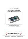
ADVR-073
Hybrid Universal Analog Digital
Voltage Regulator Operation Manual
Self Excited 7 Amp Analog / Digital Voltage Regulator
For shunt and auxiliary windings generators
With over-excitation and lost of sensing protection
Headquarters : No.3, Lane 201, Chien Fu ST., Chyan Jenn Dist., Kaohsiung, TAIWAN
Tel : + 886-7-8121771
Fax : + 886-7-8121775
URL : http://www.kutai.com.tw
1. SUMMARY
The ADVR-073 is an advance (Hybrid Analog/Digital
Voltage Regulator) design for general-purpose
isochronous stand alone applications. The
ADVR-073 uses an extremely reliable CPU (Central
Processing Unit) in its design. This eliminates
complex analogue components and circuits that are
inherently over sensitive to temperature anomalies,
as a result eliminating voltage instability and drift.
In addition, we added over excitation and loss of
sensing shutdown protections, with matching U/F,
O/E LED indicator lights. Consequently, this AVR
prevents the generator from excitation overload,
with its resulting exciter and regulator damage. It is
easy to install and flexible for use in both shunt type
and generators with auxiliary windings.
2. SPECIFICATION
Sensing Input
Voltage
Frequency
Power Input
Voltage
Output
Voltage
Current
Resistance
170 ~ 520 VAC, 1 phase 2 wire
DIP switch selectable
50 / 60 Hz, DIP switch selectable
External Volts Adjustment
7% with 1K ohm 1 watt trimmer
EMI Suppression
Internal electromagnetic interference filtering
100 ~ 300 VAC, 1 phase 2 wire
Unit Power Dissipation
Max. 8 watt
Max. 63 VDC @ 220 VAC input
Continuous 7A
Intermittent 15A for 10 sec
9 to 100 ohm
Under Frequency Protection (Factory Setting)
At 50 Hz - knee point set at 45 Hz
At 60 Hz - knee point set at 55 Hz
Voltage Regulation
< ± 0.5% ( with 4% engine governing )
Voltage Build-up
Residual voltage at AVR terminal > 5 VAC
Thermal Drift
0.03% per °C change in AVR ambient
Over Excitation Protection
78 ±5VDC @220VAC 5sec
Soft Start Ramp Time
3 sec.
Dimensions
150mm L * 115mm W * 51.5mm H
Weight
430g ± 2%
3. WIRING
3.1 A to C : Sensing Input
3.3 Power Input Voltage Selection
● DIP SW-2 is switch ON, voltage sensing range
from 170 to 260V (See Figure 2 & 3)
If generator rated voltage is 220VAC (Line to line
phase voltage), the power input B, C and sensing
input A, C can be joined (See Figure 3) or
separately (See Figure 2).
● DIP SW-2 is switch OFF, voltage sensing range
from 340 to 520V (See Figure 4)
3.2 B to C : Power Input
Power Input terminals from B to either C use 100 to
300VAC shunt or auxiliary windings.
______________________________________________________________________________________
2
ADVR-073
3.4 F+, F−
− : Connect generator field wires
5.2 Over Excitation Protection
● F+ and F− are the positive and negative excitation
output terminals.
● If you are using a standard AVR and you
overload the generator or the sensing wires get
disconnected (on a auxiliary powered AVR) , the
excitation voltage rapidly increase, causing
severe damage to the AVR or exciter. The
ADVR-073 has over excitation protection
shutdown that cuts excitation at once.
● EXT.VR is the connections for the external
voltage adjustment. Use a (1K ohm 1W) rheostat
when not in use, keep terminals shorted.
※ Always use high quality connection wire AWG16
or 1.25mm2 85-degrees C, 600V to connection
terminals A, B, C, F+ and F−.
4. DIP SWITCH SETTING
4.1 SW-1 Frequency
● DIP SW-1 switch ON, for use in 50Hz
● DIP SW-1 switch OFF, for use in 60Hz
4.2 SW-2 Sensing Voltage Selection
● DIP SW-2 switch ON, input voltage 170 to 260V
● When over excitation protection is activated and
the excitation voltage exceeds 78 ±5VDC @220V
for over 5 seconds, the AVR immediately
shutdown the excitation output, leaving only the
residual voltage output and turning on the O/E
shutdown LED. To reset, the engine must come
to a complete stop for at least 10 seconds and
then restarted.
● If over excitation protection is disabled, the
warning LED indication turn on, but the excitation
output is not disconnected.
● DIP SW-2 switch OFF, input voltage 340 to 520V
6. ADJUSTMENT
4.3 SW-3 Activate Over-Excitation Protection
6.1 VOLT : Voltage Adjustment
● DIP SW-3 switch ON, Over Excitation Protection
Disabled. If over excitation occurs, the O/E LED
turns-on, but the ADVR will not shutdown and
protect.
● DIP SW-2 switch ON, input voltage 170 to 260V
● DIP SW-3 switch OFF. Over Excitation Protection
activated. If over excitation occurs, the O/E LED
turns-on and the ADVR will shutdown excitation.
5. System Protection
5.1 Under Frequency Protection (Roll off)
● To prevent over excitation, if the generator runs
at the wrong speed the ADVR activates the under
frequency protection and decreases field
excitation.
● Dip switch 1 together with the U/F adjustment,
sets the Knee-Point frequency were this
activation takes place. This adjustment is already
factory preset.
● DIP SW-2 switch OFF input voltage 340 to 520V
6.2 STAB : Stability Adjustment
● careful adjust the STAB (Stability) adjustment,
improves the AVR and generator feedback time
to improve voltage stability.
6.3 U/F : Setting the under-frequency knee
point
● DIP SW-1 set to ON, set for 50Hz operation.
● U/F adjustment range at 50Hz is from 40 to 50Hz
(Factory preset @ 45Hz).
● DIP SW-1 set to OFF, set for 60Hz operation.
● U/F adjustment range at 60Hz is from 50 to 60Hz
(Factory preset @ 55Hz).
● When engine frequency falls under the
Knee-Point frequency setting, the U/F protection
indication LED turn on. However, when the
Generator frequency is higher than the
Knee-Point frequency the LED turns off.
______________________________________________________________________________________
ADVR-073
3
7. Startup Adjustment
7.1 Voltage Adjustment (VOLT)
WARNING
Excessive field flashing may cause damage
to the AVR or the generator exciter coil.
Set VOLT and STAB full CCW. Start generator and
wait until it reaches rated frequency. Slowly adjust
VOLT CW to its rated voltage. If you are using an
external VR, set it first to its center position before
setting volts.
7.2 Stability Adjustment (STAB)
If the generator voltage oscillates back and forth,
adjust the STAB to steady the output voltage. Over
adjustment, CW may give you large voltage swings
when changing loads, Use an analog type voltmeter
when setting STAB. Connect the voltmeter to
terminals F+ and F− and slowly adjust STAB for
minimum needle movement when varying load.
7.3 Under Frequency Adjustment (U/F)
To adjust the U/F setting, select working HZ using
DIP SW 1, start the engine and adjust engine speed
to either 55Hz or 45Hz slow adjust U/F until the red
U/F LED turns ON. Returning the engine speed
back to normal turns the LED light off.
8. Field Flashing
When setting up the AVR for the first time, the
polarity of the residual magnetism may be reversed
or too weak to operate the regulator. If reversing the
field connections does not induce build-up, and the
residual voltage is less than 5 VAC, shut down the
engine and continue with the following steps.
● Stop the generator and disconnect the field wires
(F+ and F−), apply a DC Voltage (3 to 12VDC)
using a car batteries positive to terminal F+ and
battery negative to terminal F−, using a
current-limiting resistor from 3 to 5 ohms 20 watt.
(See Figure 5).
● Flash for 3 seconds before removing the battery.
● Disconnect the AVR AC power input terminals
and restart the generator, measure the residual
voltage. If this voltage is now greater than 5VAC,
reconnect the voltage regulator, now voltage
build-up should be successful. If the voltage is
still less than 5VAC, repeat steps 7.1 and 7.2.
● If residual voltage is greater than 5VAC, but still
unable to build up voltage output, replace with a
new voltage regulator.
______________________________________________________________________________________
4
ADVR-073
9. TROUBLE SHOOTING
SYMPTOM
No Voltage Output
Low Voltage Output
Blown Fuse
Over Voltage Output
Unstable Voltage
Output
CAUSE
Engine under speed
Low residual voltage
B, C, F+, F–, Terminal connection
not properly connected
Defective generator
A, C, B, C, Terminal incorrect
connection
Defective VR or not properly
connected
Under frequency
Incorrect exciter specification
AVR Incorrect voltage selected
Over excitation current / incorrect
wiring
A, C, terminals not properly
connected or incorrectly connected
AVR Incorrect voltage selected
“STAB” Stability incorrectly adjusted
CORRECTION
Please refer to generator service manual
Please refer to section 7 “Field Flashing”
Reference from Figure 2 ~ Figure 4
Please refer to generator service manual
Reference from Figure 2 ~ Figure 4
Check connection and VR
Please refer to generator service manual
Please refer to generator service manual
Please refer to section 3 “DIP Switch setting”
Reference from Figure 2 ~ Figure 4
Reference from Figure 2 ~ Figure 4
Please refer to section 3 “DIP Switch setting”
Please refer to section 5 “Adjustment”
ATTENTION
1. AVR can be mounted directly on the engine, genset, switchgear, control panel, or any position that will not
affects operation. For dimension reference, please see Figure 1.
2. All voltage readings are to be taken with an average-reading voltmeter Meggers and high-potential test
equipment must not be used. Use of such equipment could damage the AVR.
10. FIGURE AND SIZE
N
R
G
S
~
T
1000 OHM
EXT. VR
ADVR-073
ADVR-073
UNITS:MM
SW-2 ON
Figure 1
Outline Drawing
170 ~ 260VAC
Figure 2
______________________________________________________________________________________
ADVR-073
5
N
N
R
R
S
G
S
~
T
G
~
T
1000 OHM
EXT. VR
1000 OHM
EXT. VR
ADVR-073
SW-2 ON
ADVR-073
170 ~ 260VAC
SW-2 OFF
Figure 3
340 ~ 520VAC
Figure 4
Field
N
R
G
S
20~200 OHM
SWITCH
~
T
Aux. winding
DIODE
Field
BATT.
ADVR-073
Flash with Battery
Figure 5
1000 OHM
EXT. VR
ADVR-073
With Aux. Winding
Figure 6
※ Use only original supplied spare protection fuse for fuse replacement.
※ Please accept our sincere apology if any modification in performance, specification or appearance is
made without prior notice.
______________________________________________________________________________________
6
ADVR-073