1
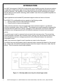
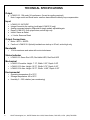
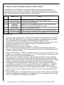
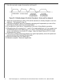
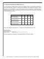
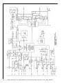
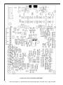
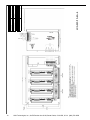
OPERATION & SERVICE MANUAL LCAM 5/15 TABLE OF CONTENTS Introduction Page 4 Features Page 5 Application Note Page 6 Technical Specifications Page 8 Startup and Calibration Page 9 APPENDIX 3 Drawing, LCAM 5/15, Installation Page 15 Drawing, LCAM 5/15, Schematic, Installation Page 16 Drawing, LCAM 5/15, Printed Circuit Board Assembly, Amplifier Page 17 Drawing, LCAM 5/15, 2-Axis Baseplate Assembly Page 18 Drawing, LCAM 5/15, 4-Axis Baseplate Assembly Page 19 H2W Technologies, Inc., 26470 Ruether Ave. #102, Santa Clarita, CA 91350, U.S.A. (888) 702-0540 INTRODUCTION The H2W Technologies LCAM 5/15 H bridge linear servo amplifier provides the optimum solution for applications which require high current loop bandwidth, low radiated electrical noise and low crossover distortion. This amplifier is constructed using surface mount technology and incorporates the latest in heat transfer technology which makes it one of the most powerful amplifiers for a given form factor. Typical applications are brushed DC permanent magnet motors and voice coil motors. The LCAM 5/15 is configurable and can operate in the following modes: 1. Velocity mode for motors with tachometer feedback. 2. Current mode for torque mode operation. A basic velocity mode servo loop for a brush type motor is shown in figure A. An external controller commands a given velocity (RPM). The velocity loop summing amplifier compares this command with the actual motor velocity, supplied by a DC tachometer on the motor shaft, and produces an error voltage proportional to the difference between the actual and commanded velocity. The velocity error is used to command motor current in the inner servo-loop. The current loop summing amplifier compares the command current (velocity error) with the actual current in the motor and produces an error voltage proportional to the difference between the actual and commanded current. Finally, the current error signal is used to produce an output to drive the motor. The velocity loop may be bypassed, and an external current command fed directly to the current loop. In this case, the external command signal controls the torque of the motor, rather than the velocity. This is known as current-mode operation. Figure A - Velocity mode servo loop for a brush type motor 4 H2W Technologies, Inc., 26470 Ruether Ave. #102, Santa Clarita, CA 91350, U.S.A. (888) 702-0540 FEATURES 5 Ergonomic Design Easy access to connections, adjustments and test points. SMT construction Provides ultra compact size, cost competitive package and high reliability. Bandwidth All servo amplifiers have a nominal 10 kHz current loop bandwidth which varies with the motor inductance. Linear output stage Provides high bandwidth, low noise and zero crossover distortion. Multimode operation Velocity mode (tachometer feedback) and Current mode (torque) . Operating Voltage Operating input voltage range: 24-75 VDC for standard LCAM 5/15 module. Basic versions Velocity and current modes. Fault protection Short from output to output, short from output to ground, amplifier RMS over current, and amplifier over temperature. Status indicator LEDs indicate status on the LCAM 5/15. Dedicated inputs Command signals, +/- limits, inhibit, reset, and fault. Dedicated outputs Fault out and motor current monitor. Current limit Peak motor current is adjustable. External fault reset An input is provided to reset the amplifier in the event of a fault. CE compliant All servo amplifiers are CE marked. H2W Technologies, Inc., 26470 Ruether Ave. #102, Santa Clarita, CA 91350, U.S.A. (888) 702-0540 APPLICATION NOTE POWER DISSIPATION CONSIDERATIONS AND CALCULATIONS WHEN USING LINEAR DC SERVO AMPLIFIERS: When selecting a linear amplifier, the following ratings of the amplifier should be known in order to properly size the amplifier to your system requirements: 1– The total wattage, peak current, and voltage rating of all the semiconductors installed on the heat sink of the output power stage of the amplifier. Output transistor ratings for the LCAM 5/15 series are: Voltage: 250 Volts Peak current: 60 A; Continuous current: 30 A (Normally shipped with 12-20A limit) Total wattage @25 deg C.:1200 Watts The LCAM 5/15 series amplifier is a module style amplifier requiring an external unregulated single polarity DC power supply. H2W Technologies offers various unregulated power supplies for the LCAM 5/15 series amplifiers. The LCAM 5/15series amplifier is also available in multi-axis configurations. That is, there are two basic baseplate assemblies namely 2-axis and 4-axis baseplate assemblies that have built-in AC to DC power supplies (un-regulated) and cooling fans. The 2-axis baseplate assembly contains one AC to DC power supply, one fan, and up to two LCAM 5/15 amplifier modules. The 4axis baseplate assembly contains one AC to DC power supply, two fan, and up to four LCAM 5/15 amplifier modules. For multi-axis applications, it is always recommended to use three phases power transformers for minimizing ripple voltage during high current demand scenarios where all axis motors are running at full load simultaneously. H2W Technologies offers various isolated three phases power transformers. 2– Typical continuous internal rating of the amplifiers running at normal room conditions is: LCAM 5/15 series; 250 Watts continuous For most applications, the above heat sinking is adequate. However, if you have a usage mode where the heat sink temperature becomes excessive, please contact H2W Technologies and we can furnish a larger heat sink with greater air flow for your application. 6 H2W Technologies, Inc., 26470 Ruether Ave. #102, Santa Clarita, CA 91350, U.S.A. (888) 702-0540 Use the following relationships to calculate amplifier dissipation : 1) Pd = Im x Vb (watts) Where: Pd = Total watts delivered from bus Im = Motor current Vb = Bus voltage 2) Pm = Im x Vm (watts) Where: Pm = Total power (watts) dissipated in motor Vm = Motor voltage 3) Pa =Im x Vb - Im x Vm Where: Pa = Total watts dissipated at amplifier From the above relationship, it can be surmised that the worst case dissipation occurs when the amplifier has to deliver a high continuous current at a low motor speed, i.e., less motor BEMF and more current. For some applications, a power resistor can be added in series with the motor thus shifting some of the power dissipation from the amplifier to the resistor. 7 H2W Technologies, Inc., 26470 Ruether Ave. #102, Santa Clarita, CA 91350, U.S.A. (888) 702-0540 TECHNICAL SPECIFICATIONS Output LCAM 5/15: 15A peak, 5A continuous, (forced air cooling required) Note: Large motor and Small motor versions have different velocity loop compensation. Input LCAM 5/15: 24-75VDC Integral forced air fan cooling (multi-axis LCAM 5/15 only) Analog command signals: differential & single ended, adjustable gain Reset: LCAM 5/15: pull up/pull down, active high only Inhibit: Same as Reset +/- Limits: Same as Reset Output Connections Motor : MTR + & MTRFault out: LCAM 5/15: Optically isolated can sink up to 50 mA, active high only Bandwidth 10 kHz maximum and varies with motor inductance Status Indicator LCAM 5/15: Green Run LED, Red Inhibit LED, Red Fault LED Mechanical LCAM 5/15 module: Height: 7.13”, Width: 2.23”, Depth: 5.69” LCAM 5/15 2-Axis: Height: 10.75”, Width: 9.75”, Depth: 6.93” LCAM 5/15 4-Axis: Height: 10.75”, Width: 14.90”, Depth: 6.93” Environmental 8 Operating temperature 0 to 55°C Storage temperature -40 to 80°C Humidity 5 – 95% relative (non-condensing) H2W Technologies, Inc., 26470 Ruether Ave. #102, Santa Clarita, CA 91350, U.S.A. (888) 702-0540 STARTUP AND CALIBRATION This section contains the procedure required for initial start up and amplifier calibration. The LCAM 5/15 series amplifier can be configured to run in velocity mode (x.x) and current mode (y.y). Required Equipment: Oscilloscope, voltmeter & battery box. The battery box serves as a step input voltage command, applying and removing a flashlight battery can also be used for this function. Refer to the technical specifications page and the drawings in the appendix for the information needed to supply the correct power and to wire the model you are starting up. An isolation transformer is needed for the multi-axis LCAM 5/15. An isolated power supply (unregulated is OK) providing the necessary voltage is required for the LCAM 5/15 module. H2W can provide appropriate transformers and power supplies. Consult an H2W applications engineer or sales person for assistance. A. Initial Start Up: When applying power to start up your amplifier system for the first time, we recommend you follow this procedure. If you have already gone through this procedure you can skip to the appropriate calibration procedure. 1. Check for any loose or damaged components. 2. Check that all connections are tight. 3. Be sure that the motor mechanism is clear of obstructions. If the mechanism has limited motion, e.g: a lead-screw, set the mechanism to mid-position. 4. Disconnect the signal and auxiliary inputs. 5. Be sure the Loop-Gain pot(s) are fully CCW (RV6 for LCAM 5/15). This will prevent the motor from running away in velocity mode when power is applied. 6. Check for the correct AC voltage before connecting to LCAM 5/15 multi-axis amplifier. The DC Bus (amplifier supply-voltage) will be 1.4 times greater than the AC value. If the voltage is correct, remove power and connect AC source to amplifier inputs. For the LCAM 5/15 module amplifier, check for the correct DC voltage before connecting to the amplifier power input. 7. Work on only one amplifier axis at a time for LCAM 5/15 multi-axis amplifiers. 9 H2W Technologies, Inc., 26470 Ruether Ave. #102, Santa Clarita, CA 91350, U.S.A. (888) 702-0540 B. Calibration of the Velocity Mode Amplifier (LCAM 5/15 Series): The amplifier, in this configuration, receives an analog, bi-polar input command which is proportional to the motor velocity. The amplifier receives velocity feedback from a tachometer which is usually mounted to the rear of the motor. The following pots will be set during calibration: (Note: RV6 is a single turn pot and RV1-RV5 are 10-turn pots.) Pots Name of Pot Notes RV1 Signal Gain, SIG Sets the input voltage to velocity ratio for signal input. RV4 Tach Gain, TACH Sets the DC tachometer gain. RV6 Loop Gain, LOOP GAIN Used to shut off uncalibrated amplifiers. When the loop gain is fully CCW, no current is delivered to the motor. RV2 Balance, BAL Used to null any offset in system. RV3 Compensation, COMP Used in conjunction with tach. gain to set the system bandwidth. RV5 Current Limit, I LIMIT Sets the maximum motor current. Shipped set CCW (min. current). PROCEDURE: 1. Apply main power and fan power. Visually confirm a green LED. Depending on the configuration of the Inhibit, Reset and +/-Limits, it may be necessary to make appropriate connections to those terminals before the amplifier will be enabled and energize the motor. 2. Slowly turn the Loop Gain (RV6) CW fully. Motor should be stopped or turning slowly. If the motor starts running away, remove the power, reverse the tach leads, and retest. 3. Set Balance (RV2) for zero motor rotation. 4. Install a micro-shunt at J3 connector (across J3-1 to J3-2). Note: For single-ended signal input amplifier, a micro-shunt is permanently installed at J3 connector. On the other hand, the micro-shunt should be removed for differential input amplifier after the calibration process. 5. Connect oscilloscope to J1-7 (MTR I) and battery box to J1-1 (J1-4 is common for both). The voltage on J1-7 is a function of motor current: 1V = 2.0A. While applying a step input voltage, adjust Current Limit (RV5) for desired peak current. The purpose of the following procedure is to set the system bandwidth to obtain a criticallydamped response or a one hook overshoot response with the maximum possible Tach. Gain. There are many possible settings of Tach. Gain and Compensation which will yield the desired waveform: The optimum setting will occur when Tach Gain is as CW as possible and Compensation is as CCW as possible. However, the servo loop may become unstable (the motor oscillates or hunts) with a very low (near CCW) setting of Compensation. In this case, stability is the limiting factor: At no time should the servo-loop be allowed to be unstable. Amplifiers are normally shipped with the Tach. Gain (RV4) set at 100%. This is a good place to start. If you are unsure of where the Tach. Gain is set, turn the Tach Gain (RV4) fully CW (up to 10 turns). 6. Connect oscilloscope to J1-3 (TACH IN) and J1-4 is common. Set battery box for a DC signal output to obtain approximately 400RPM. The RPM may be set by measuring the tach voltage at J1-3, e.g., 2.8VDC for a 7V/KRPM tach is 400RPM. 10 H2W Technologies, Inc., 26470 Ruether Ave. #102, Santa Clarita, CA 91350, U.S.A. (888) 702-0540 7. Pulse the input and compare the waveform with figure B. Figure B - Critically damped, One Hook Overshoot, Under and Over damped 8. Adjust the Compensation pot (RV3) CCW until the waveform is critically damped or one hook overshoot. Then proceed to step 10. 9. If the desired waveform cannot be obtained by adjusting the Compensation pot, back off the Tach Gain pot (CCW) a few turns and repeat step 8. 10. Do not adjust the Tach Gain or Compensation for the rest of the calibration procedure. 11. With battery box still connected at J1-1 and J1-4 for single-ended input (or if your system uses the Differential input, move battery box to J1-1 and J1-2, and remove micro-shunt at J3 connector), set battery box for a known DC voltage. Adjust the Signal Gain pot (RV1) to obtain the desired motor velocity. 12. If the motor is rotating in the wrong direction for a given input polarity, remove the power and reverse both the motor leads and the tach leads. 13. Remove the battery box, and repeat step 3. 14. Calibration complete. Reconnect signal wires. 11 H2W Technologies, Inc., 26470 Ruether Ave. #102, Santa Clarita, CA 91350, U.S.A. (888) 702-0540 C. Calibration of the Current Mode Amplifier (LCAM 5/15 Series): The amplifier in this configuration, receives an analog, bi-polar input command which is proportional to the required motor current (motor torque). The following potentiometers (pots) will be set during calibration: (Note: RV6 is a single turn pot and RV1-RV5 are 10-turn pots.) Pots Name of Pot Notes RV1 Signal Gain, SIG Sets the input voltage to velocity ratio for signal input. RV4 Tach Gain, TACH Sets the DC tachometer gain. RV6 Loop Gain, LOOP GAIN Used to shut off uncalibrated amplifiers. When the loop gain is fully CCW, no current is delivered to the motor. RV2 Balance, BAL Used to null any offset in system. RV3 Compensation, COMP Used in conjunction with tach. gain to set the system bandwidth. RV5 Current Limit, I LIMIT Sets the maximum motor current. Shipped set CCW (min. current). PROCEDURE: 1. Apply main power and fan power. Visually confirm a green LED. Depending on the configuration of the Inhibit, Reset and +/-Limits, it may be necessary to make appropriate connections to those terminals before the amplifier will be enabled and energize the motor. 2. Slowly turn the Loop Gain (RV6) pot CW fully. The Motor should be stopped or turning slowly. Set the Balance (RV2) for 0V at J1-7 (MTR I). 3. Install a micro-shunt at J3 connector (across J3-1 to J3-2). Note: For single-ended signal input amplifier, a micro-shunt is permanently installed at J3 connector. On the other hand, the micro-shunt should be removed for differential input amplifier after the calibration process. 4. Connect an oscilloscope to J1-7 (MTR I) and a battery box to J1-1 (J1-4 is common for both). The voltage on J1-7 is a function of motor current: 1V = 2.0A. While applying a step input voltage, adjust the Current Limit (RV5) for the desired peak current. If the desired peak current cannot be achieved with the Current Limit pot full CW, increase the input Signal Gain (RV1) by turning in the CW direction. 5. With the battery box still connected at J1-1 and J1-4 for single-ended input (or if your system uses the Differential input, move battery box to J1-1 and J1-2, and remove micro-shunt at J3 connector), set the battery box for a known DC voltage. Apply ±input signal pulses and adjust the Signal Gain pot (RV1) to obtain the desired current gain of the amplifier. 6. If the motor is rotating in the wrong direction for a given input polarity, remove the power and reverse the motor leads. 7. Remove the battery box, and repeat step 2. 8. Calibration complete. Reconnect signal wires. 12 H2W Technologies, Inc., 26470 Ruether Ave. #102, Santa Clarita, CA 91350, U.S.A. (888) 702-0540 D. Calibration Setup Record (LCAM 5/15 Series): It is good practice to keep a record of all the pot settings. Doing so will facilitate calibration on future units and repair on this unit. Although not a substitute for the calibration procedure, it will at least get you "in the ballpark." Remove the power and allow all capacitors to discharge before taking measurements. Note: The balance pot should not be measured in this fashion, set per step 3 in the calibration procedure. Pot/Dip-Switches AMP1 AMP2 AMP3 AMP4 Signal Gain pot wiper TP2 to common (ohms): Tach Gain pot wiper TP3 to common (ohms): Compensation pot wiper TP4 to common (ohms): Current Limit pot wiper TP5 to common (ohms): Note: Tach voltage is measured at J1-3. Common for all measurements is at J1-4. Date data taken: / / Serial number S/N: _________________________________ Model number: LCAM 5/15_________________________ Note any changes to components or any special features in the space below: 13 H2W Technologies, Inc., 26470 Ruether Ave. #102, Santa Clarita, CA 91350, U.S.A. (888) 702-0540 APPENDIX 14 H2W Technologies, Inc., 26470 Ruether Ave. #102, Santa Clarita, CA 91350, U.S.A. (888) 702-0540 15 H2W Technologies, Inc., 26470 Ruether Ave. #102, Santa Clarita, CA 91350, U.S.A. (888) 702-0540 5.0 A @ 25°C Ambient (with forced air cooling) Adjustable Latches when current exceeds ±5 A fo 2 seconds Amplifier faults and is inhibited if the heat sink temperature reaches 75°C Amplifier enabled, normal operating condition Input Command Signal Gain Low Speed Electronic Circuit Breaker (LS/ECB) Amplifier Over Temperature Green Run LED -40°C to +80°C 5% to 95% non-condensing Storage Temperature Humidity Molex P/N: 22-12-2154-7478 Signal Connector (J1) 10 A FAST, Bussman P/N: BK-AGC-10 1 A FAST, Bussman P/N: BK-AGC-1 DC Input BUS Fuse (F1) Ground Fuse (F2) Fuse Table Phoenix P/N: 17 92 78 6 Motor and DC Input Connector (J2) Mating Connectors 0°C to +55°C Operating Temperature Red Fault LED Amplifier disabled, non-latched condition (External Inhibited) Amplifier over temperature or LS/ECB (Latched Condition) 15 A @ 25°C Ambient (with forced air cooling) Continuous Output Current Red Inhibit LED 24 - 75 VDC max. Peak Output Current Specifications and Features DC Bus input Voltage 16 H2W Technologies, Inc., 26470 Ruether Ave. #102, Santa Clarita, CA 91350, U.S.A. (888) 702-0540 LCAM 5/15 CIRCUIT BOARD ASSEMBLY 17 H2W Technologies, Inc., 26470 Ruether Ave. #102, Santa Clarita, CA 91350, U.S.A. (888) 702-0540 18 H2W Technologies, Inc., 26470 Ruether Ave. #102, Santa Clarita, CA 91350, U.S.A. (888) 702-0540 110 - 130 VAC, Single Phase, 50/60 Hz Unregulated 70 VDC max. @ 50 VAC Input 5.0 A @ 25°C Ambient (with forced air cooling) per amplifier LCAM 5/15 (QTY:4) Derived DC Bus Voltage Continuous Output Current Amplifier Modules Molex P/N: 22-12-2154-7478 Signal Connector LCAM 5/15-2A-2 Phoenix P/N: 17 92 78 6 Motor and DC Input Connector Mating Connectors 17 - 53 VAC, Single or Three Phase Fan Input Voltage Specifications and Features AC Input Voltage 19 H2W Technologies, Inc., 26470 Ruether Ave. #102, Santa Clarita, CA 91350, U.S.A. (888) 702-0540 LCAM 5/15 (QTY:4) Molex P/N: 22-12-2154-7478 Signal Connector LCAM 5/15-4A-4 Phoenix P/N: 17 92 78 6 Motor and DC Input Connector Mating Connectors 5.0 A @ 25°C Ambient (with forced air cooling) per amplifier Unregulated 70 VDC max. @ 50 VAC Input Amplifier Modules 110 - 130 VAC, Single Phase, 50/60 Hz Derived DC Bus Voltage Continuous Output Current 17 - 53 VAC, Single or Three Phase Fan Input Voltage Specifications and Features AC Input Voltage 26470 Ruether Avenue #102, Santa Clarita, California 91350, USA. Telephone: (661) 251-2081 | Fax: (61) 251-2067 www.h2wtech.com e-mail: [email protected]