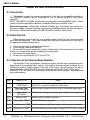
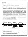
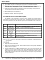
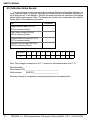
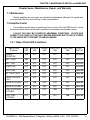
1
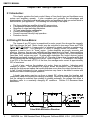
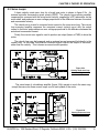
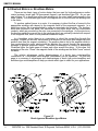
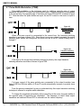
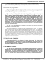
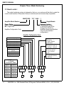
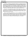
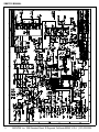
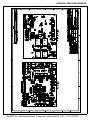
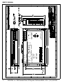
OPERATION
&
SERVICE MANUAL
for
Torque-Switch Series®
Model SMA7215
Brush Type Amplifier System
MANUAL#: 7015-2040
REVISION: (A)
DATE: 15APR98.
208 Standard Street, El Segundo, California 90245, U.S.A. (310) 322-3026
Table of Contents
Page
Introduction............................................................................................................... 5
Chapter One: Description, Features and Specifications
1.1 Description .................................................................................................. 6
1.2 Features ...................................................................................................... 6-7
1.3 Specifications .............................................................................................. 8
1.3.1 Input and Output Power .................................................................. 8
1.3.2 Signal Inputs ................................................................................... 8
1.3.3 Digital Inputs ................................................................................... 8
1.3.4 System ............................................................................................ 8
1.3.5 Outputs............................................................................................ 8
1.3.6 Mechanical ...................................................................................... 8
Chapter Two: Theory of Operation
2.1 Introduction.................................................................................................. 9
2.2 Driving DC Servo Motors............................................................................. 9
2.3 Servo Loops................................................................................................. 10
2.4 Brushed Motors vs Brushless Motors .......................................................... 11-12
2.5 Operation of Output Switching Transistors ................................................. 12
2.6 “ H ” Type Output Bridge Configuration ...................................................... 12
2.7 Pulse-Width-Modulation (PWM).................................................................. 13-14
2.8 Current-Loop Operation .............................................................................. 14
2.9 Velocity-Loop Operation .............................................................................. 14
2.10 Protection Circuits...................................................................................... 14
GLENTEK Inc. 208 Standard Street, El Segundo, California 90245, U.S.A. (310) 322-3026
2
SMA7215 MANUAL
Chapter Three: Model Numbering
Page
3.1 How to order ................................................................................................ 15
Chapter Four: Installation
4.1 Introduction .................................................................................................. 16
4.2 Mounting ...................................................................................................... 16
4.3 Wiring........................................................................................................... 16-19
4.3.1 RFI/EMI and Wiring Technique .......................................................... 16
4.3.2 Wire Size and Type ............................................................................ 17
4.3.3 Connector Size and Type ................................................................... 17-18
4.3.3.1 The Power Connector............................................................... 18
4.3.3.2 The Signal Connector ............................................................... 19
4.3.4 Amplifier Connections ........................................................................ 18-19
4.3.4.1 The Power Connections ........................................................... 18
4.3.4.2 The Signal Connections............................................................ 18-19
4.3.5 Test Point ........................................................................................... 19
Chapter Five: Configuration
5.1 Introduction .................................................................................................. 20
5.2 Logic Input Configuration ............................................................................. 2 0
5.2.1 +15V/+5 Logic Level Configuration .................................................... 20
5.2.2 Velocity/Voltage Feedback Mode and Current Mode Configuration....20
5.2.3 Integrator Configuration...................................................................... 20
Chapter Six: Start Up and Calibration
6.1 Introduction .................................................................................................. 21
6.2 Initial Start Up .............................................................................................. 21
6.3 Calibration of the Velocity Mode Amplifier ................................................... 21-23
6.4 Calibration of the Current Mode Amplifier.................................................... 23-24
6.5 Calibration Setup Record............................................................................. 25
3
GLENTEK Inc. 208 Standard Street, El Segundo, California 90245, U.S.A. (310) 322-3026
TABLE OF CONTENTS
Page
Chapter Seven: Maintenance, Repair, and Warranty
7.1 Maintenance ................................................................................................ 26
7.2 Amplifier Faults ............................................................................................ 26-29
7.2.1 Table of Fault LED Conditions ........................................................ 26
7.2.2 Under Voltage Fault ........................................................................ 27
7.2.3 High Speed Electronic Circuit Breaker (HS/ECB) Fault.................. 27
7.2.4 Low Speed Electronic Circuit Breaker (LS/ECB) Fault ................... 27
7.2.5 Over Temp Fault ............................................................................. 27
7.2.6 Over Voltage Fault .......................................................................... 28
7.2.7 Resetting A Fault............................................................................. 28
7.3 Amplifier Failure........................................................................................... 28
7.4 Factory Repair ............................................................................................. 28
7.5 Warranty ...................................................................................................... 29
Appendix: Amplifier Drawings
SMA7215 Power Board Installation Schematics (7015-2044-000).................... 31
SMA7215 Power Board Assembly Drawing (7015-2002-000)........................... 32
SMA7215-1 Installation Drawing (7015-2030-000)............................................ 33
GLENTEK Inc. 208 Standard Street, El Segundo, California 90245, U.S.A. (310) 322-3026
4
SMA7215 MANUAL
Introduction
Glentek's brush type DC servo motors and amplifiers offer the ultimate in low maintenance
and high performance motion control. Glentek offers a full line of matched motors and amplifiers
to meet virtually every motion control application.
This manual provides all the technical information necessary to install, configure, operate,
and maintain our TORQUE-SWITCH™ series, brush type servo amplifier, model SMA7215.
There is also an informative theory-of-operation chapter.
We suggest that you take the time to read this manual from cover-to-cover before
attempting to work with these amplifiers for the first time. If at any time you have questions,
or have any special requirements, please feel free to call and discuss them with a Glentek
applications engineer. We are happy to provide both off-the-shelf and custom products. With over
three decades in the servo-motor/amplifier business, we have a vast pool of applications
knowledge waiting to assist you.
Thank you for selecting Glentek for your motion control needs. It is our goal to save you time,
money, and to provide you with a superior product.
5
GLENTEK Inc. 208 Standard Street, El Segundo, California 90245, U.S.A. (310) 322-3026
CHAPTER 1: DESCRIPTION, FEATURES AND SPECIFICATIONS
Chapter One: Description, Features and Specifications
1.1 Description:
This brush type servo amplifier system has been designed to offer you, our customer, a
large degree of flexibility and customization with a standard, in stock product. The amplifier is
of a modular, ‘open’ construction for ease of installation and service.
Each amplifier accepts a bipolar DC control input. The polarity of this signal determines
the direction of rotation. This signal may be used to control either the velocity (RPM) or the
current (torque) of the motor(see Servo Loops, section 2.3). The amplifier provides
Pulse-W idth Modulated (PWM) power to the motor in proportion to the input signal.
Each amplifier has several ‘logic’ inputs to stop the motor in one or both directions.
These inputs are very useful for connecting to mechanical limit switches or digital equipment.
Each amplifier has several protection circuits to protect the amplifier, motor, and operator
from almost any kind of fault. Several LED’s show what fault has occurred, and a separate
output can be used to signal other equipment.
1.2 Features:
• Ergonomic design:
Easy access to connections, adjustments, and test points.
• Wide operating
24-220VDC.
• Complete isolation:
Complete isolation from input to output.
• Signal input:
Input has up to 15,000A/V gain and will accept +/-13VDC.
buss voltage:
• Dual mode operation: The amplifier may be configured for velocity (RPM) control or
current (torque) control.
• BEMF velocity mode This mode uses back EMF to deduce motor speed for feedback with
IR Comp.
(Factory Option):
• Current limit:
control. Optional IR compensation yields 3% or better velocity
control without a tachometer.
Maximum motor current is adjustable.
• Digital limit/enable
Three separate logic inputs can stop the motor in either or both
Inputs:
directions. Inputs may be configured for active-high or active- l o w ,
pull-up or pull-down termination, and a 0 to +5VDC or 0 to +15VDC range. See Logic Input
Configuration, section 5.2.
GLENTEK Inc. 208 Standard Street, El Segundo, California 90245, U.S.A. (310) 322-3026
6
SMA7215 MANUAL
7
•
Open-collector output goes low in the event of a fault.
Externally forcing the output low will inhibit the amplifier. T h i s
allows all fault outputs in a multi-axis system to be connected together (wire-ORed) to shut
down all amplifiers
should any amplifier have a fault.
•
Silent operation:
Carrier frequency is 20KHz.
•
Short circuit protection:
Complete short circuit and ground fault protection.
•
LED diagnostics:
Red LED(S) illuminate to display various fault conditions and
a green LED illuminates to indicate normal operating
conditions.
•
Frequency response:
750 Hz minimum for Velocity Loop.
•
Frequency response:
2 KHz minimum for Current Loop.
•
Manual and external
fault reset:
Push button and a separate input is provided to reset the
amplifier after a fault.
•
High-Speed Electronic
Circuit Breaker
(HS/ECB):
Instantly shuts down the amplifier in the event of a short
across outputs and or ground fault condition.
(i.e. amplifier exceeds 80A for 10microseconds)
•
Low-Speed Electronic
Circuti Braker
(LS/ECB):
Shuts down the amplifier if the amplifier is operated above
the maximum continuous current rating(i.e. 13A for standard
18A for high power) for 5seconds.
•
Foldback current limit:
Folds back the continuous current delivered by the amplifier
to 15A(standard) or 20A(high power) if the amplifier is
operated above the maximum continuous current rating for
2 seconds.
•
Over/under voltage
and over temperature:
These circuits constantly monitor amplifier powersupply voltages, and amplifier-heatsink temperature. They
will shut down the amplifier in the event of any out-ofspecification condition. The overvoltage protection circuit is
set to turn on at 250VDC.
•
Surface mount
technology:
Constructed with surface mount components.
•
Clamp Circuitry:
Apply brake to motor and releases after 100msec to inhibit
the amplifier.
Fault input/output:
GLENTEK Inc. 208 Standard Street, El Segundo, California 90245, U.S.A. (310) 322-3026
CHAPTER 1: DESCRIPTION, FEATURES AND SPECIFICATIONS
1.3 Specifications:
The amplifier module requires an external DC power supply which must include a bridge
rectifier, buss capacitor, solid-state relay and shunt regulator. Forced air cooling is required to
meet the maximum power ratings specified below.
1.3.1 Input and Output Power:
•
•
Buss Voltage, B+:
Output Power:
24-220VDC.
15A(continuous), 25A(peak).
20A(continuous), 40A(peak).
Standard
High Power
1.3.2 Signal Inputs:
Signal Input
Single-ended
Voltage
VDC
(maximum)
+/-70
Impedance
(minimum)
Ω
10,000
+/-90
10,000
Tachometer input
Velocity Gain Current Gain
Amp./Volt
Amp./Volt
15,000
0-5
7,000
1.3.3 Digital Inputs:
•
•
•
+/-Limit, Clamp and Reset:
Fault (as input):
Typical for all digital inputs:
+/-50V max. Terminated by 10,000Ω.
+40V/-5V max. Terminated by 10,000Ω.
Digital inputs have hysteresis with thresholds at
1/3 and 2/3 of +5V or +15V depending on
range
select dip-switch.
1.3.4 System:
•
•
•
•
•
Drift offset over temperature reference to input:
Frequency response (Velocity loop):
Frequency response (Current loop):
Dead band:
Form factor:
0.01mV/ o C max.
750Hz min.
2KHz min.
None.
1.01.
1.3.5 Outputs:
•
Fault (as output):
•
•
Motor current:
LS/ECB, HS/ECB
Overvolt, Overtemp:
Active low. Open-collector output can sink 100mA
maximum through 10Ω.
Bipolar output. 1V=5A.
Open-collector outputs can sink 40mA max.
1.3.6 Mechanical:
Dimensions L x W x H (inches): 7.12 x 1.36 x 4.79
Weight (lbs):
1.28
GLENTEK Inc. 208 Standard Street, El Segundo, California 90245, U.S.A. (310) 322-3026
8
SMA7215 MANUAL
Chapter Two: Theory of Operation
2.1 Introduction:
This chapter contains the basic control theory of how brush type and brushless servo
motors and amplifiers operate. It also compares and contrasts the advantages and
disadvantages of brushless and brush type motors and amplifiers to help you select which is
best suited for your application. The following is a summary of the topics:
•
•
•
•
•
•
•
The theory behind an amplifier driving DC servo motors.
A comparison between brush type and brushless motors.
Operation of output switching transistors.
“H Type” output bridge configuration.
Pulse-Width-Modulation (PWM).
Current-Loop and Velocity-Loop operation..
Protection circuits.
2.2 Driving DC Servo-Motors:
The torque of any DC motor is proportional to motor current: the stronger the magnetic
field, the stronger the pull. Motor current may be controlled in two ways: linear and PWM
(Pulse-W idth Modulation). Linear control is achieved by simply inserting a resistance in
series with the motor. This resistance is usually a partially turned on transistor. The
transistor is said to be in its "linear" region. Linear amplifiers are simple, accurate, and
effective. However, they are very inefficient and they generate a lot of heat. Linear amplifiers
are used when low electrical noise, high bandwidths (2KHz or higher) and or low inductance
(less than 1mH) motors are used. In pulse-width modulation the control devices (output
transistors) are rapidly turned full on and full off. The ratio of the on time (the pulse width) and
off time determines the average motor current. Refer to figure 2.1. For example: if the output
is on 25% of the time and off 75% of the time, the average motor current is approximately
25% of maximum.
A coil of wire, such as the windings of a motor, forms an inductor. Inductors resist
changes in current. This resistance to change, known as reactance, acts to dampen or
average the high-current spikes that would otherwise occur when the output devices are on.
In fact, if motor inductance is low, external inductors may have to be added in series with
each motor lead to ensure proper operation.
A brush type motor may be run from a steady DC voltage since the brushes and
commutator switch the current from winding to winding. However, a brushless motor requires
that the voltage be switched from winding to winding externally; the voltage that drives a
brushless motor is a constantly changing AC waveform. Section 2.5 discusses these
waveforms.
Figure 2.1
Pulse Width Modulation Waveform
9
GLENTEK Inc. 208 Standard Street, El Segundo, California 90245, U.S.A. (310) 322-3026
CHAPTER 2: THEORY OF OPERATION
2.3 Servo Loops:
A basic velocity mode servo loop for a brush type motor is shown in figure 2.2a. An
external controller commands a given velocity (RPM). The velocity loop summing amplifier
compares this command with the actual motor velocity, supplied by a DC tachometer on the
motor shaft, and produces an error voltage proportional to the difference between the actual
and commanded velocity.
The velocity error is used to command motor current in the inner servo-loop. The current
loop summing amplifier compares the command current (velocity error) with the actual
current in the motor and produces an error voltage proportional to the difference between the
actual and commanded current.
Finally, the current error signal is used to produce an output (linear or PWM) to drive the
motor.
The velocity loop may be bypassed, and an external current command fed directly to the
current loop. In this case, the external command signal controls the torque of the motor,
rather than the velocity. This is known as current-mode operation.
Figure 2.2a
Velocity mode sevo loop
for a brush type motor
The servo-loops of a brushless amplifier (figure 2.2b) operate in much the same way,
except there are now three current loops, one for each phase of the motor.
Figure 2.2b
Velocity mode sevo loop
for a brushless motor
GLENTEK Inc. 208 Standard Street, El Segundo, California 90245, U.S.A. (310) 322-3026
10
SMA7215 MANUAL
2.4 Brushed Motors vs. Brushless Motors:
There are two basic types of motor design that are used for high-performance motion
control systems: brush type PM (permanent magnet), and brushless type PM. As you can
see in figure 2.3, a brush type motor has windings on the rotor (shaft) and magnets in the
stator (frame). In a brushless type motor, the magnets are on the rotor and the windings are
in the stator.
To produce optimal torque in a motor, it is necessary to direct the flow of current to the
appropriate windings with respect to the magnetic fields of the permanent magnets. In a
brush-type motor, this is accomplished by using a commutator and brushes. The brushes,
which are mounted in the stator, are connected to the motor wires, and the commutator
contacts, which are mounted on the rotor, are connected to the windings. As the rotor turns,
the brushes switch the current flow to the windings which are optimally oriented with respect
to the magnetic field, which in turn produces maximum torque.
In a brushless motor there is no commutator to direct the current flow through the
windings. Instead, an encoder, hall sensors or a resolver on the motor shaft senses the rotor
position (and thus the magnet orientation). The position data is fed to the amplifier which in
turn commutates the motor electronically by directing the current through the appropriate
windings to produce maximum torque. The effect is analogous to a string of sequencing
Christmas lights: the lights seem to chase each other around the string. In this case, the
magnets on the rotor "chase" the magnetic fields of the windings as the fields "move" around
the stator.
The relative advantages and/or disadvantages of a brush type motor/amplifier
combination vs. a brushless motor/amplifier combination can be significant. On the next
page is a summary of advantages and disadvantages of brush type motor/amplifiers and
brushless type motor/amplifiers to help you decide which type to select for your applications.
Figure 2.3
Brush type and Brushless type Motors
11
GLENTEK Inc. 208 Standard Street, El Segundo, California 90245, U.S.A. (310) 322-3026
CHAPTER 2: THEORY OF OPERATION
Brushless Motors/Amplifiers
Brushed Motors/Amplifiers
Advantages
Disadvantages
No scheduled maintenance and no brush dust
is generated.
Motor brushes must be checked periodically for
wear and excess brush dust.
Higher RPM limits.
Approximately 3000RPM maximum.
Lower inertia/torque ratio.
Higher inertia to torque ratio.
Dissipates heat more efficiently due to windings Not as efficient at dissipating heat. Heat is
being located in stator.
trapped at rotor and shortens bearing life.
Safer for explosive atmospheres. Quieter and
less electrical noise generated.
Brushes spark and generate electrical and
audible noise.
Disadvantages
Advantages
Amplifiers are complicated and expensive.
Amplifiers are simpler and less expensive.
Higher torque ripple.
Lower torque ripple.
No Industry standard packaging.
Industry standard packaging.
2.5 Operation of Output Switching Transistors:
The output transistors, for all intents and purposes, operate in only two states. They are
analogous to ON/OFF switches. When an output transistor is OFF , there is no current
flowing through it (its resistance is infinite). When an output transistor is ON, current flows
through it (its resistance is near zero). When the transistor is ON, it is technically referred to
as being in saturation.
2.6 “H” Type Output Bridge Configuration:
The output configuration of the amplifier is an “H TYPE” bridge (see figure 2.4 for
schematic representation of an output bridge with a motor connected).
Figure 2.4
Schematic representation of
an output bridge with a
motor connected.
The advantage of an “H TYPE” output bridge configuration is that by controlling the
switching of the opposite pairs of transistors, current can be made to flow through the motor
in either direction using a single-polarity power supply.
To provide motor current in one direction, transistor A and C are turned ON, while B and
D remain in the OFF state. To provide motor current in the other direction, B and D are
turned ON, while A and C remain in the OFF state.
GLENTEK Inc. 208 Standard Street, El Segundo, California 90245, U.S.A. (310) 322-3026
12
SMA7215 MANUAL
2.7 Pulse-Width-Modulation (PWM):
Pulse-width-modulation is the technique used for switching opposite pairs of output
transistors ON and OFF to control the motor drive current. When zero current is commanded
to the current loop, the opposite pairs of transistor are turned ON and OFF as shown in figure
2.5. Note that since the pulse widths are equal, the net DC current in the motor is equal to
zero.
Figure 2.5
Transistor switching
waveform at zero
current
When a non-zero current is commanded to the current loop, the transistor switching
waveform is as shown in figure 2.6A. Since there is a non-zero current command, the output
transistor pulse widths will change and the motor will see a net DC current flowing from A
through C.
Figure 2.6A
Transistor switching
waveform when current
flows from A through C
If the input to the current loop had been changed in polarity, the output transistor
switching waveform would be as shown in figure 2.6B.
Figure 2.6B
Transistor switching
waveform when current
flows from B through D
If a larger current of the same polarity was commanded to the output transistor (see
figure 2.6B) the ON-time widths of B and D would automatically increase to provide more
current.
From the previous examples it is easy to understand why this output transistor switching
technique is referred to as pulse-width-modulation.
To change the magnitude and polarity of the current flow in the motor, the pulse widths of
the opposite pairs of transistors are modulated. The frequency at which these output
transistors are switched ON and OFF is referred to as the ‘carrier frequency’.
13
GLENTEK Inc. 208 Standard Street, El Segundo, California 90245, U.S.A. (310) 322-3026
CHAPTER 2: THEORY OF OPERATION
Now that we have a good understanding of how the current is provided from an “H TYPE”
pulse-width-modulated (PWM) bridge, let’s analyze the operation of the current loop.
2.8 Current Loop Operation:
Please refer to figure 2.2A for a diagram of the current loop. In control electronics the
symbol Sigma (with the circle around it) is referred to as a ‘summing junction’. The manner
in which this summing junction operates is as follows:
The current-command signal (also referred to as the velocity error signal when received
from the output of the velocity loop, as shown in figure 2.2A) is added to the current feedback
signal. The signal resulting from this addition, is referred to as the “current error” signal. This
current-error signal is fed into the current amplifier, which in turn produces a current in the
motor. A voltage which is proportional to the motor current is developed across Rs (shunt
resistor). This voltage is referred to as the “current feedback” signal. The current in the
motor increases until the current-command signal. At this point the current error signal drops
to zero. and the actual current is equal to the commanded current. If anything happens to
disturb either the current command signal, or the current feedback signal, the same process
occurs again until the current feedback signal is equal in magnitude to the current command
signal, but opposite in polarity.
The type of loop described above is referred to as a “servo loop” because the current
servos about a commanded value.
We are surrounded in our everyday lives by a multitude of servo loops. For example,
many of today’s luxury cars have what is called ‘automatic climate control’. To operate this
servo loop, you set the climate control to the temperature that you wish to be maintained in
the interior of the car (current command signal). The selected temperature is then summed
with the actual temperature from a thermometer (current feedback), and the output (current
error signal) activates either the heater or the air conditioner until the actual temperature as
measured by the thermometer (current feedback signal) is equal in magnitude, but opposite
in polarity, to the set temperature.
2.9 Velocity Loop Operation:
Please refer to figure2.2A for a diagram of a typical velocity loop. The velocity loop’s
operational description is analogous to the current loop description, except for the fact that
the input signal is called the Velocity Command and the feedback signal from the DC
tachometer is called the Velocity Feedback.
2.10 Protection Circuits:
The High and Low Speed Electronic Circuit Breakers(HS/ECB and LS/ECB) protect the
amplifier and motor from being damaged by high motor current(specified max. peak and rms
current values). The Over Temperature and Over Voltage detection circuits will shut off the
amplifier when the temperature of the amplifier or the buss(B+) voltage exceeds a specified
limit. Also, there are circuits which limit the motor from running in either or both directions.
GLENTEK Inc. 208 Standard Street, El Segundo, California 90245, U.S.A. (310) 322-3026
14
SMA7215 MANUAL
Chapter Three: Model Numbering
3.1 How to order:
The model numbering system is designed so that you, our customer will be able to create the
correct model number of the product that you need as quick and as accurately as possible.
SMA7215XX - YYY - QQQ - 1
Amplifier Model Number
Single Module
Power Rating
Omit = Standard
HP = High Power
Amplifier Configuration Code
Optional Custom
Configuration Code
(A numerical code will be
assigned by Glentek to
amplifiers whose specifications
vary from the standard
configuration.)
Amplifier Configuration Code
±Limit
±Limit
Clamp
Clamp
Reset
Reset
0=L, 1=H
0=U, 1=D
0=L, 1=H
0=U, 1=D
0=L, 1=H
0=U, 1=D
Differential or Single-ended
Signal Inputs:
0 = Single; (Default)
1 = Differential;
Velocity or Current Mode:
(see section 2.8 and 2.9)
0 = Velocity; 1 = Current,
On Board Power Supply
+15V/+5V on pull-up:
0 = +15V; (Default)
1 = +5V;
DC Buss Voltage
0 = 24-220VDC;(Default)
1 = SPECIAL;
↑ See section 5.2 ↑
Type A: U=0 & L=0
(Default)
Type B: D=1 & H=1
Type C: U=0 & H=1
Type D: D=1 & L=0
4-BIT Binary
to Digital
Conversion Table
0000=0
1000=8
0001=1
1001=9
0010=2
1010=A
0011=3
1011=B
0100=4
1100=C
0101=5
1101=D
0110=6
1110=E
0111=7
1111=F
15
0
0
GLENTEK Inc. 208 Standard Street, El Segundo, California 90245, U.S.A. (310) 322-3026
CHAPTER 4: INSTALLATION
Chapter Four: Installation
4.1 Introduction:
This chapter provides the necessary information to make all the wiring connections for
the amplifiers to operate properly.
4.2 Mounting:
Appendix contains all the assembly drawings, and mechanical information necessary to
install the amplifiers. The amplifier package should be mounted in a clean, dry enclosure, free
of dust, oil, or other contaminants.
NEVER INSTALL THE AMPLIFIER PACKAGE IN ANY LOCATION
WHERE FLAMMABLE OR EXPLOSIVE VAPORS ARE PRESENT.
IMPORTANT: At least 3 inches must be allowed between the cooling fans and any other
surface. The clearance to any other side of the amplifier package is not critical, although
sufficient space should be allowed for easy wiring and servicing.
4.3 Wiring:
DO NOT APPLY POWER UNTIL INSTRUCTED TO DO SO.
4.3.1 RFI/EMI and Wiring Technique:
IMPORTANT: All PWM equipment inherently generates radio-frequency
interference (RFI), and wiring acts as antennae to transmit this interference. In addition,
motors inherently generate electromagnetic interference (EMI). Unless the wiring is very
short, some sort of shielding on the motor wires is necessary to meet FCC RFI/EMI
guidelines and to protect other equipment from the effects of RFI/EMI. We recommend
that shielded wire be used, or the wires should be run in metallic conduit. The shield or
conduit should be connected to the amplifier baseplate, which in turn must be earth
grounded. In addition, a conductor of the same gauge as the motor wires must be
connected from the motor case to the amplifier baseplate to provide protection from
shock hazard. The earth grounding is necessary to meet National Electrical Code (NEC)
requirements as well as suppressing RFI/EMI.
Additional RFI suppression may be obtained by placing inductors in each motor
lead near the amplifier. Consult a Glentek applications engineer for inductor
recommendations. Glentek stocks a complete line of inductors for virtually every
application.
IMPORTANT: The signal wiring to tachometer (if used) and the signal inputs to
the amplifier are susceptible to noise pickup. Excessive noise pickup will cause erratic
amplifier operation. We urge that each signal input line each be run in separate,
twisted-pair, shielded cable. In each case the shield should be terminated at the amplifier
end only to a common terminal. We also recommend that the signal lines be kept as far
as possible from any power or motor wires.
GLENTEK Inc. 208 Standard Street, El Segundo, California 90245, U.S.A. (310) 322-3026
16
SMA7215 MANUAL
4.3.2 Wire Size and Type:
IMPORTANT: To ensure safe operation, Glentek strongly recommends that all wiring
conform to all local and national codes.
Recommended Wire Size and Type:
•
Motor Wires:
•
•
•
•
•
Motor Case Ground:
Main Power:
Fan Power:
Signal & Tach Input:
Logic Inputs/Outputs:
14AWG, shielded - Standard Version.
12AWG, shielded - High Power Version.
Same as motor wires, or use metallic conduit.
14AWG, twisted.
16AWG, twisted.
22AWG, twisted-pair, shielded.
22AWG, shielded with its return lead.
4.3.3 Connector Size and Type:
4.3.3.1 The Power Connector - TB1:
All amplifiers are shipped with the right angle AUGAT terminal block mounted as it
power connector . The vertical angle AUGAT terminal block and the PHOENIX connector
are two options one can choose to use for the power connector. The specifications of all
the mentioned connectors are listed as follows:
17
•
AUGAT® RDI 6 Series Tri-Barrier Terminal Blocks(AUGAT P/N: 6PCR-04) - Default
:
- Screw Size/Spacing: 6 (#6-32 on .375" centers).
- Terminal Style: PC (Printed Circuit Pin).
- Terminal Orientation: R (Right Angle).
- Number of Screw Terminals: 04 (4 screw positions).
- Terminal lugs: Thomas & Betts (T&B P/N: A116 for 18awg wire, B19 for
14awg wire and C133 for 12/10awg wire).
•
AUGAT® RDI 6 Series Tri-Barrier Terminal Blocks(AUGAT P/N: 6PCV-04):
- Screw Size/Spacing: 6 (#6-32 on .375" centers).
- Terminal Style: PC (Printed Circuit Pin).
- Terminal Orientation: V (Vertical Angle).
- Number of Screw Terminals: 04 (4 screw positions).
- Terminal lugs: Thomas & Betts (T&B P/N: A116 for 18awg wire, B19 for
14awg wire and C133 for 12/10awg wire).
•
PHOENIX CONTACT, COMBICON Headers and Plugs with 7.62mm pitch
(HEADER PART# GMSTBA 2,5/4-G-7,62),
(PLUG PART# GMVSTBR 2,5/4-ST-7,62):
- header with side panels, plug-in direction parallel to PCB.
- 4 positions.
- color: green.
GLENTEK Inc. 208 Standard Street, El Segundo, California 90245, U.S.A. (310) 322-3026
CHAPTER 4: INSTALLATION
4.3.3.2 The Signal Connector - J1:
The signal connector is supported by the molex® KK .100" (2,54mm) Centerline
Connector System.
• Mating Header: molex® 7478 Series Right Angle Square Pin Friction Lock
•
Header (molex P/N: 22-12-2164):
- 16 pins.
- .025" (0,64mm) right angle square brass pins.
- 94V-0 nylon housing.
Mating Connector: molex® 2695 Series .100" (2,54mm) Center Crimp Terminal
•
Housing (molex P/N: 22-01-3167):
- red nylon housing.
- 16 positions.
- with polarizing rib.
Crimp Terminals: molex® Crimp Terminals (molex P/N: 08-55-0102):
- 15 microinch select gold plated.
- brass.
4.3.4 Amplifier Connections:
4.3.4.1 The Power Connections - TB1:
Signal Name
Terminal
Notes
BUS RETURN,
B-
TB1-1
DC Buss -
BUSS, B+
TB1-2
DC Buss +
MOTOR -
TB1-3
Motor -
MOTOR +
TB1-4
Motor +
4.3.4.2 The Signal Connections - J1:
Signal Name
Terminal
Notes
DIFF SIG IN (+)
J1-1
Differential signal input, NOT USED.
DIFF SIG RET (-)
J1-2
Differential signal return, NOT USED.
SIG IN (+)
J1-3
Single-ended signal.
COMMON
J1-4
Common for all signals and shields.
TACH IN
J1-5
Tachometer Input. Not used in current-mode operation.
GLENTEK Inc. 208 Standard Street, El Segundo, California 90245, U.S.A. (310) 322-3026
18
SMA7215 MANUAL
Signal Name
Terminal
Notes
MTR CUR
J1-6
Scale factor: 1V=5A.
LIMIT +
J1-7
Inhibits the motor in the +direction.
LIMIT -
J1-8
Inhibits the motor in the -direction.
CLAMP
J1-9
Brakes the motor and go into inhibit after a period of 100m
seconds.
FAULT
J1-10
Goes low if there is a fault in the amplifier. May be
externally forced low to stop motor rotation in both
directions.
COMMON
J1-11
Common for all signals and shields.
RESET
J1-12
Resets the fault latch. May also be used as an inhibit input.
LS/ECB
J1-13
Goes high if the Low Speed Electronic Circuit Breaker
turns on.
HS/ECB
J1-14
Goes high if the High-Speed Electronic Circuit
Breaker turns on.
OVERVOLT
J1-15
Goes high if the buss voltage rises above 250VDC.
OVERTEMP
J1-16
Goes high if the temperature of the amplifier and motor
rises above the specified temp.
4.3.5 Test Point - J2:
Signal Name
19
Terminal
Notes
COMMON
J2-1
Common for all signals and shields.
SIG
J2-2
Single-ended signal input.
TACH
J2-3
Tachometer input. Not used in current-mode operation.
DIFF SIG GAIN
J2-4
Differential signal Input gain. NOT USED.
SIG GAIN
J2-5
Single-ended signal Input gain.
TACH GAIN
J2-6
Tachometer feedback gain.
COMP
J2-7
Compensation. Use in conjunction with tachometer gain to
set the system bandwidth.
GLENTEK Inc. 208 Standard Street, El Segundo, California 90245, U.S.A. (310) 322-3026
CHAPTER 5: CONFIGURATION
Chapter Five: Configuration
5.1 Introduction:
Each amplifier has several configuration options. This chapter describes these options
and how to implement them. If desired, Glentek will be happy to pre-configure your amplifiers.
NOTE: Each amplifier is configured and shipped according to the model number
(instructions to construct a model number is in chapter three) when the order is placed. It is
important for the user to realize that any adjustment on the dip-switches by the user will result
in discrepancies between the model number and the actual configuration of the amplifier.
5.2 Logic Input Configuration:
There are three logic inputs: Limit+/-, Clamp and Reset. They may be configured for
active-high or active-low signals, and pulled-up or pulled-down termination (type A, B, C, and
D). All logic inputs have a selectable 0 to +5VDC or 0 to +15VDC range.
Type "A": Requires grounding of input to disable the amplifier (pull-up, active-low).
Type "B": Requires a positive voltage at input to disable the amplifier (pull-down,
activehigh).
Type "C": Requires grounding of input to enable the amplifier (pull-up, active-high).
Type "D": Requires a positive voltage at input to enable the amplifier (pull-down,
activelow).
The following table shows the dip switches that need to be configured for the Type A, B,
C, and D configurations. The standard configuration is shown in bold.
Type A
Type B
Type C
Type D
LIMIT+/-
S1-4 - OFF
S1-7 - ON
S1-4 - ON
S1-7 - OFF
S1-4 - OFF
S1-7 - OFF
S1-4 - ON
S1-7 - ON
CLAMP
S1-3 - OFF
S1-7 - ON
S1-3 - ON
S1-7 - OFF
S1-3 - OFF
S1-7 - OFF
S1-3 - ON
S1-7 - ON
RESET
S1-2 - OFF
S1-5 - ON
S1-2 - ON
S1-5 - OFF
S1-2 - OFF
S1-5 - OFF
S1-2 - ON
S1-5 - ON
5.2.1 +15V/+5V Logic Level Configuration (Default:S1-1=ON):
•
+15V: S1-1 = ON; +5V: S1-1 = OFF;
5.2.2 Velocity/Voltage Feedback Mode and Current Mode Configuration:
•
•
Velocity or BEMF Voltage Feedback Mode: S1-9:ON and S1-10:OFF;
Current Mode: S1-10:ON and S1-9:OFF;
5.2.3 Integrator Configuration (Default:S1-8=OFF):
The integrator switch is turned ON to lower the integration proportional break point in the
velocity PID loop. The lower break point may be required with motors having high inductance
amatures. This switch should remain off unless instructed to turn on.
GLENTEK Inc. 208 Standard Street, El Segundo, California 90245, U.S.A. (310) 322-3026
20
SMA7215 MANUAL
Chapter Six: Start Up and Calibration
6.1 Introduction:
This chapter contains the procedure required for initial start up and amplifier calibration.
The SMA7215 amplifier can be configured to run in velocity mode(6.3) and current
mode(6.4).
NOTE: The SMA7215 amplifier can also be pre-configured to run in the BEMF mode. Please
consult a Glentek applications engineer for detailed information on BEMF mode.
Required Equipment: Oscilloscope, voltmeter & battery box. The battery box serves as a
step input voltage command, applying and removing a flashlight battery can also be used for
this function. Glentek sells a battery box BB-700 which is ideal for this function.
6.2 Initial Start Up:
When applying power to start up your amplifier system for the first time, we recommend
you follow this procedure. If you have already gone through this procedure you can skip to
the appropriate calibration procedure.
1. Check for any loose or damaged components.
2. Check that all connections are tight.
3. Be sure that the motor mechanism is clear of obstructions. If the mechanism has limited
motion, e.g: a lead-screw, set the mechanism to mid-position.
4. Disconnect the signal inputs.
5. Be sure the Loop-Gain pot (RV1) is fully CCW.
6.3 Calibration of the Velocity Mode Amplifier:
The amplifier, in this configuration, receives an analog, bi-polar input command which is
proportional to the required motor velocity. The amplifier receives velocity feedback from a
tachometer which is usually mounted to the rear of the motor. The following pots will be set
during calibration: (Note: RV1-RV5 are single turn pots and RV6-RV13 are 12-turn pots.)
Note: RV2, RV3, RV4 and RV5 are factory set and should not be adjusted. Adjusting these
pots voids warranty.
Pots
Name of Pot
RV1
RV8
Loop Gain,
LOOP GAIN
Differential Gain,
DIFF SIG GAIN
Signal Gain,
SIG GAIN
Balance, BAL
RV9
Tach. Gain, TACH
RV6
RV7
Notes
Used to shut off uncalibrated amplifiers. When the loop gain is
fully CCW, no current is delivered to the motor.
Sets the input voltage to velocity ratio for differential signal input.
Sets the input voltage to velocity ratio for single-ended signal input.
Used to null any offsets in system.
Sets the DC tachometer gain.
RV10 Compensation, COMP Used in conjunction with tach. gain to set the system bandwidth.
RV13
21
Current Limit, I LIMIT
Sets the maximum motor current. Shipped set CCW (min. current).
GLENTEK Inc. 208 Standard Street, El Segundo, California 90245, U.S.A. (310) 322-3026
CHAPTER 6: START UP AND CALIBRATION
PROCEDURE:
1. Apply main power and fan power.
2. Slowly turn Loop Gain (RV1) CW. Motor should be stopped or turning slowly. If motor starts
running away, remove power, reverse the tach leads, and retest.
3. Set Balance (RV8) for zero motor rotation.
4. Connect oscilloscope to J1-6 (MTR I) and battery box to J1-3 (J1-4 is common for both). The
voltage on J1-6 is a function of motor current: 1V=5A. While applying a step input voltage,
adjust Current Limit (RV13) for desired peak current.
The purpose of the following procedure is to set the system bandwidth to obtain a criticallydamped response or a one hook overshoot response with the maximum possible Tach. Gain.
There are many possible settings of Tach. Gain and Compensation which will yield the
desired waveform. The optimum setting will occur when Tach Gain is as CW as possible and
Compensation is as CCW as possible. However, the servo loop may become unstable (the
motor oscillates or hunts) with a very low (near CCW) setting of Compensation. In this case,
stability is the limiting factor. At no time should the servo-loop be allowed to be unstable.
Amplifiers are normally shipped with Tach. Gain (RV9) set at 75%. This is a good place to
start. If you are unsure of where Tach. Gain is set, turn Tach Gain (RV9) fully CW (up to 12
turns), then CCW 4 turns.
5. Connect oscilloscope to J1-5 (TACH IN) and J1-4 is common. Set battery box for a DC signal
output to obtain approximately 400RPM. The RPM may be set by measuring the tach voltage
at J1-5, e.g., 2.8VDC for a 7V/KRPM tach is 400RPM.
6. Pulse the input and compare the waveform with figure 6.1.
Figure 6.1
Critically damped, One Hook Overshoot,
Under and Over damped waveforms
7. Adjust the Compensation pot CCW until the waveform is critically damped or one hook
overshoot. Then proceed to step 9.
8. If the desired waveform cannot be obtained by adjusting the Compensation pot, back
off(CCW) the Tach Gain pot a few turns and repeat step 7.
GLENTEK Inc. 208 Standard Street, El Segundo, California 90245, U.S.A. (310) 322-3026
22
SMA7215 MANUAL
9. Do not adjust Tach Gain or Compensation for the rest of the calibration procedure.
10. With battery box still connected at J1-3 and J1-4 for single-ended input, set battery box for a
known DC voltage. Adjust Signal Gain (RV7) to obtain the desired motor velocity.
11. If the motor is rotating in the wrong direction for a given input polarity, remove power and
reverse both the motor leads and the tach leads.
12. Remove battery box, and repeat step 3.
13. Calibration complete. Reconnect signal wires.
6.4 Calibration of the Current Mode Amplifier:
The amplifier in this configuration, receives an analog, bi-polar input command which is
proportional to the required motor current(motor torque). The following potentiometers (pots) will
be set during calibration: (Note: RV1-RV5 are single turn pots and RV6-RV13 are 12-turn pots.)
Pots
Name of Pot
RV1
Loop Gain
LOOP GAIN
Differential Gain
DIFF SIG GAIN
Signal Gain
SIG GAIN
Balance
BAL
Current Limit
I LIMIT
RV6
RV7
RV8
RV13
Notes
Used to shut off uncalibrated amplifiers. When the loop gain is
fully CCW, no current is delivered to the motor.
Sets the input voltage to current ratio for differential signal input.
Sets the input voltage to current ratio for single-ended signal input.
Used to null any offsets in system.
Sets maximum motor current. Shipped set at full CCW
(minimum current limit).
Note: RV2, RV3, RV4 and RV5 are factory set and should not be adjusted. Adjusting these pots
voids warranty.
PROCEDURE:
1. Apply main power and fan power.
2. Slowly turn Loop Gain(RV1) pot CW. Motor should be stopped or turning slowly. Set Balance
(RV8) for 0V at J1-6 (MTR I).
3. Connect oscilloscope to J1-6 (MTR I) and battery box to J1-3 (J1-4 is common for both). The
voltage on J1-6 is a function of motor current: 1V=5A. While applying a step input voltage,
adjust Current Limit (RV13) for desired peak current. If desired peak current cannot be
achieved with Current Limit pot full CW, increase either the input signal or Signal Gain (RV7)
for single-ended input.
23
GLENTEK Inc. 208 Standard Street, El Segundo, California 90245, U.S.A. (310) 322-3026
CHAPTER 6: START UP AND CALIBRATION
4. With battery box still connected at J1-3 and J1-4 for single-ended input, set battery box for a
known DC voltage. Apply ±input signal pulses and adjust the Signal Gain (RV7) pot to
obtain the desired current gain of the amplifier.
5. If the motor is rotating in the wrong direction for a given input polarity, remove power and
reverse the motor leads.
6. Remove battery box, and repeat step 2.
7. Calibration complete. Reconnect signal wires.
GLENTEK Inc. 208 Standard Street, El Segundo, California 90245, U.S.A. (310) 322-3026
24
SMA7215 MANUAL
6.5 Calibration Setup Record:
It is good practice to keep a record of all pot settings. Doing so will facilitate calibration on
future units and repair on this unit. Although not a substitute for the calibration procedure, it
will at least get you "in the ballpark." Remove the power and allow all capacitors to discharge
before taking measurements. Note: The balance pot should not be measured in this fashion,
set per step 3 in the calibration procedure.
Pot
Resistance
Signal Gain pot wiper (RV7) at
J2-5 to common (ohms):
Tach Gain pot wiper (RV9) at
J2-6 to common (ohms):
Compensation pot wiper (RV10) at
J2-7 to common (ohms):
Current Limit pot wiper (RV13) at
TP1-K to common (ohms):
Dip-switch
1
2
3
4
5
6
7
8
9
10
S1
Note: Tach voltage is measured at J2-3. Common for all measurements is at J1-11.
Date data taken:
/
/
Serial number S/N: _________________________________
Model number:
SMA7215_________________________
Note any changes to components or any special features in the space below:
25
GLENTEK Inc. 208 Standard Street, El Segundo, California 90245, U.S.A. (310) 322-3026
CHAPTER 7: MAINTENANCE, REPAIR, and WARRANTY
Chapter Seven: Maintenance, Repair, and Warranty
7.1 Maintenance:
Glentek amplifiers do not require any scheduled maintenance, although it is a good idea
to occasionally check for dust build up or other contamination.
7.2 Amplifier Faults:
If an amplifier should cease to operate and one or more of the fault LED's are lit, review
the sections which follow on the fault in question for information and possible causes.
A FAULT CAN ONLY BE CAUSED BY ABNORMAL CONDITIONS. LOCATE AND
CORRECT THE CAUSE OF THE FAULT BEFORE REPEATED RECYCLING OF POWER
TO THE AMPLIFIER TO PREVENT POSSIBLE DAMAGE.
7.2.1 Table of Fault LED Conditions:
Input or Fault
Condition
RUN
LED
HS/ECB
LED
LS/ECB
LED
OVER VOLT
LED
OVER TEMP
LED
FAULT
OUTPUT
NORMAL
OPERATION
ON
OFF
OFF
OFF
OFF
GROUND
LIMIT + (ON)
ON
OFF
OFF
OFF
OFF
GROUND
LIMIT - (ON)
ON
OFF
OFF
OFF
OFF
GROUND
CLAMP (ON)
OFF
OFF
OFF
OFF
OFF
GROUND
RESET (ON)
OFF
OFF
OFF
OFF
OFF
PULL-UP
EXT. FAULT (ON)
OFF
OFF
OFF
OFF
OFF
PULL-UP
UNDER VOLTAGE
(+15V)
OFF
OFF
OFF
OFF
OFF
PULL-UP
HS/ECB (LATCHED)
OFF
ON
OFF
OFF
OFF
PULL-UP
LS/ECB (LATCHED)
OFF
OFF
ON
OFF
OFF
PULL-UP
OVER VOLTAGE B+
(LATCHED)
OFF
OFF
OFF
ON
OFF
PULL-UP
OVER TEMP
(LATCHED)
OFF
OFF
OFF
OFF
ON
PULL-UP
GLENTEK Inc. 208 Standard Street, El Segundo, California 90245, U.S.A. (310) 322-3026
26
SMA7215 MANUAL
7.2.2 Under Voltage Fault:
When the +15VDC power supply is below +12VDC, a level that would cause unreliable
operation, the Run LED will turn off, a Fault Output is generated, and the amplifier is inhibited.
This is not a latched condition: that is, if the problem is resolved the amplifier will resume
operation.
The following is a list of possible causes:
Main buss line voltage is too low.
Bad power supply.
•
•
7.2.3 High Speed Electronic Circuit Breaker (HS/ECB) Fault:
When the peak output of the amplifier exceeds 80A for 10 microseconds, the Run LED
will turn off, the HS/ECB LED will turn on and a Fault Output is generated, and the amplifier is
inhibited. NOTE: This is a latched condition.
The following is a list of possible causes:
Shorted motor leads.
Motor inductance too low.
Short from a motor lead to ground.
•
•
•
7.2.4 Low Speed Electronic Circuit Breaker (LS/ECB) Fault:
When the RMS output of the amplifier exceeds 13A for standard or 18A for high power
for 5 seconds, the Run LED will turn off, the LS/ECB LED will turn on and a Fault Output is
generated, and the amplifier is inhibited. NOTE: This is a latched condition.
The following is a list of possible causes:
Binding or stalling of motor shaft due to excessive mechanical overload.
Overload of amplifier output to motor.
Large reflected load inertia.
•
•
•
7.2.5 Over Temp Fault:
When the amplifier heatsink temperature has reached a level that, if exceeded, would
damage the output transistors, the Run LED will turn off, the OVER TEMP LED is latched on,
a Fault Output is generated, and the amplifier is inhibited. NOTE: This is a latched condition.
The following is a list of possible causes:
Loss of cooling or fans are defective or airflow is blocked.
Excessive rise in cooling air temperature due to cabinet ports being blocked or excessive
hot air being ingested.
• Extended operational duty cycle due to mechanical overload of motor or defective motor.
•
•
27
GLENTEK Inc. 208 Standard Street, El Segundo, California 90245, U.S.A. (310) 322-3026
CHAPTER 7: MAINTENANCE, REPAIR, and WARRANTY
7.2.6 Over Voltage Fault:
When the DC Buss voltage reaches 250VDC, the Run LED will turn off, the
Overvoltage LED will turn on and a Fault Output is generated, and the amplifier is
inhibited. NOTE: This is a latched condition.
The following is a list of possible causes:
Main Buss line voltage is too high.
Decelerating a large inertial load. When decelerating, a DC motor acts as a
generator. If the inertial load is large, the generated voltage can pump up the
DC-Buss. If this fault occurs, you may need a Regen Clamp. Consult Glentek.
•
•
7.2.7 Resetting A Fault:
The fault latch may be reset by pushing the Reset button, activating the Reset input
J1-12 or by removing power and allowing the filter capacitor(s) to discharge. Note that
the fault latch will not reset unless the fault has been cleared.
7.3 Amplifier Failure:
If an amplifier should fail, that is, if it should cease to operate with no apparent fault, the
drawings in appendix will enable a skilled technician to trouble shoot an amplifier to even
lower levels.
7.4 Factory Repair:
Should it become necessary to return an amplifier to Glentek for repair, please follow the
procedure described below:
1. Reassemble the unit, if necessary, making certain that all the hardware is in place.
2. Tag the unit with the following information:
A. Serial number and model number.
B. Company name, phone number, and representative returning the unit.
C. A brief notation explaining the malfunction.
D. Date the unit is being returned.
3. Repackage the unit with the same care and fashion in which it was received. Label
the container with the appropriate stickers (e.g: FRAGILE: HANDLE WITH CARE).
4. Contact a Glentek representative, confirm that the unit is being returned to the
factory
and obtain an RMA (Return Material Authorization) number. The RMA
number must
accompany the unit upon return to Glentek.
5. Return the unit by the best means possible. The method of freight chosen will
directly affect the timeliness of its return.
Glentek also offers a one day repair service in the unlikely event that your system is down
and you do not have a replacement amplifier module.
GLENTEK Inc. 208 Standard Street, El Segundo, California 90245, U.S.A. (310) 322-3026
28
SMA7215 MANUAL
7.5 Warranty:
Any product, or part thereof, manufactured by Glentek, Inc., described in this manual,
which, under normal operating conditions in the plant of the original purchaser thereof, proves
defective in material or workmanship within one year from the date of shipment by us, as
determined by an inspection by us, will be repaired or replaced free of charge, FOB our
factory, El Segundo, California, U.S.A. provided that you promptly send to us notice of the
defect and establish that the product has been properly installed, maintained, and operated
within the limits of rated and normal usage, and that no factory sealed adjustments have been
tampered with. Glentek's liability is limited to repair or replacement of defective parts.
Any product or part manufactured by others and merely installed by us, such as an
electric motor, etc., is specifically not warranted by us and it is agreed that such product or
part shall only carry the warranty, if any, supplied by the manufacturer of that part. It is also
understood that you must look directly to such manufacturer for any defect, failure, claim or
damage caused by such product or part.
Under no circumstances shall Glentek, Inc. or any of our affiliates have any liability
whatsoever for claims or damages arising out of the loss of use of any product or part sold to
you. Nor shall we have any liability to yourself or anyone for any indirect or consequential
damages such as injuries to person and property caused directly or indirectly by the product
or part sold to you, and you agree in accepting our product or part to save us harmless from
any and all such claims or damages that may be initiated against us by third parties.
29
GLENTEK Inc. 208 Standard Street, El Segundo, California 90245, U.S.A. (310) 322-3026
Appendix
Amplifier Drawings
GLENTEK Inc. 208 Standard Street, El Segundo, California 90245, U.S.A. (310) 322-3026
30
SMA7215 MANUAL
31
GLENTEK Inc. 208 Standard Street, El Segundo, California 90245, U.S.A. (310) 322-3026
APPENDIX: AMPLIFIER DRAWINGS
GLENTEK Inc. 208 Standard Street, El Segundo, California 90245, U.S.A. (310) 322-3026
32
GLENTEK Inc. 208 Standard Street, El Segundo, California 90245, U.S.A. (310) 322-3026
J2
TEST POINTS
POTS
COMMON
SIGNAL
TACH
DIFF SIG GAIN
SIG GAIN
TACH GAIN
COMP
RUN
S1
LEDS
CUR MODE
VEL MODE
INTEGRATOR
LIM & CLAMP H/L
N/A
RESET H/L
LIMIT U/D
CLAMP U/D
RESET U/D
+15/+5
OVER TEMP
33
DIFF GAIN
SIG GAIN
BAL
TACH
COMP
IR COMP
OVER VOLT
FLDBK
LS/ECB
I LIMIT
HS/ECB
J1
DIFF SIG +
DIFF SIG
SIGNAL IN
COMMON
TACH
MTR CUR
LIMIT +
LIMIT
CLAMP
FAULT
COMMON
RESET
LS/ECB
HS/ECB
OVERVOLT
OVERTEMP
1
2
3
4
5
6
7
8
9
10
11
12
13
14
15
16
LOOP GAIN POT
RESET SWITCH
SMA7215-1
CAUTION
HIGH VOLTAGE
TB1
BRUSHTYPE AMPLIFIER
BUS RET 1
B+ 2
MOTOR
3
MOTOR + 4
SMA7215 MANUAL
High Bandwidth Brush Type Servo Amplifiers
•
•
Linear Brush type servo amplifiers to 2.25KW
PWM (Pulse-width-modulated) Brush type servo amplifiers to 70KW
High Bandwidth Brushless Servo Amplifiers
•
•
Linear Brushless servo amplifiers to 2.25KW
PWM (Pulse-width-modulated) Brushless servo amplifiers to 65KW
Permanent Magnet DC Brush Type Servo Motors
•
•
Continuous Torques to 335 in. lb.
Peak Torques to 2100 in. lb.
Permanent Magnet DC Brushless Servo Motors
•
•
Continuous Torques to 1100 in. lb.
Peak Torques to 2200 in. lb.
208 STANDARD STREET, EL SEGUNDO, CALIFORNIA 90245, USA.
TELEPHONE: (310)322-3026 FAX: (310)322-7709
208 Standard Street, El Segundo, California 90245, U.S.A. (310) 322-3026


![MX2 sync [final].vp](http://vs1.manualzilla.com/store/data/005975841_1-4533d2555e3004ab9339335fb150c7a8-150x150.png)