1
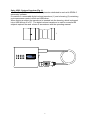
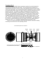
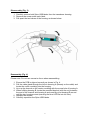
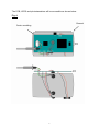
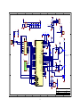
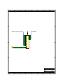
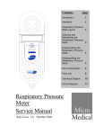
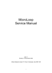
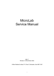
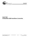
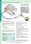
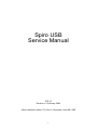
Spiro USB Service Manual 075-12 Revision 1.0 February 2004 Micro Medical Limited, P.O. Box 6, Rochester, Kent ME1 2AZ 1 Spiro USB - System Overview (Fig. 1) The Spiro USB is a PC connected spirometer dedicated to work w ith SPIDA 5 spirometry software. It consists of a removable digital volume transducer (1) and a housing (2) containing a microprocessor control circuit and USB driver. When testing a subject the transducer is inserted into the housing, which is plugged into a USB socket of a PC. The digital volume transducer is used to measure the subjects expired flow and volume in accordance with the operating manual. 1 2 2 Transducer (Fig. 2) The Micro Medical digital volume transducer consists of an acrylic tube with a vane positioned between two swirl plates. The low inertia vane is attached to a stainless steel pivot which is free to rotate on two jewelled bearings mounted at the centre of the swirl plates. As air is passed through the transducer a vortex is created by the swirl plates which causes the vane to rotate in a direction dependant upon the direction of air flow. The number of rotations is proportional to the volume of air passed through the transducer and the frequency of rotation is proportional to the flow rate. The transducer housing consists of a main body which contains a pair of light emitting diodes (LED’s) and phototransistors. The transducer is fixed to the mouthpiece holder which pushes into the main body and is captured by an “O” ring seal. The LED’s produce infra red beams which are interrupted by the vane twice per revolution. This interruption is sensed by the phototransistors. The output from the collector of each phototransistor will be a square wave with a phase difference between the two of + or - 90 degrees depending upon the direction of flow. There is no routine maintenance required for the transducer other than cleaning according to the instructions in the operating manual. Micro Medical Digital Volume Transducer Rotating vane Infra red emitter Swirl plate Jewelled bearing Infra red detector Volume = k X No. of pulses Volume proportional to the number of pulses Flow proportional to the puse frequency Flow = k / pulse period 3 Disassembly (Fig. 3) 1. Carefully remove both Spiro USB labels from the transducer housing. 2. Remove the screw under each label. 3. Pull apart the two halves of the housing as shown below: Reassembly (Fig. 4) Please note: Do not use excessive force when reassembling. 1. Ensure the PCB is aligned correctly as shown in Fig. 4. 2. Pull the cable gland through the hole in housing A (already on the cable) and locate the centre moulding into the housing. 3. Line up the channel on the centre moulding with the screw hole of housing A. 4. When refitting housing B, locate the moulded bracket (with the nut) between the end of the channel and housing A and carefully pivot housing B around until the two housings meet (ensuring the blue LED fits into it’s hole). 5. Replace the screws. 6. Carefully reposition the Spiro USB labels. 4 The PCB, LED’S and phototransistors will be accessible as shown below: Fig. 4. Channel Centre moulding 5 Microprocessor control circuit, see drawing 075-01 and 075-02 The microprocessor control circuit monitors the transducer pulses, carries out the spirometry routines, and communicates with the PC via a USB driver under the control of it’s internal program. Power for the processor circuit is derived from the 5 volt USB power line. The power line is filtered by C12, L1 and C13. The filtered 5 volt is regulated down to 3.3 v olts by the linear regulator, U7. U7 also provides a reset signal for the microprocessor. The microprocessor, U3, is a Hitachi HD64F2318 16 bit microprocessor with 256K of flash memory and 8K of Ram. The system clock is supplied by 12MHz crystal, X1. There is also 512 Kbytes of external RAM, U8, used for storing pulses during a spirometry manoeuvre. The internal flash memory is used to store the microprocessor firmware. Calibration data and system data is stored in an EEPROM, U2. Communication to the EEPROM is carried out using a two wire serial connection to pins 54 and 55 of the microprocessor. If the device is ever replaced, the unit will have to undergo factory recalibration. Ambient temperature is monitored by a solid-state temperature sensor, U9. It communicates with the microprocessor via a one wire serial interface on pin 90. The ambient temperature reading is used for adjusting inspiratory volume at ambient temperature to volume at body temperature. The supply to the two series LED’s, mounted inside the transducer housing, is provided through TR1, which is switched on by pin 4 of the microprocessor during a spirometry manoeuvre. Inside the transducer housing the two phototransistors used to detect the interrupted infra-red beam are in open collector configuration. The pull up resistor for the two phototransistors is provided by R7 and R8. Pulses from the phototransistor, TR2, are applied to the pulse timing input of the processor, pin 5, after being squared up by the action of the Schmitt i nverter, U4. Pulses from the second phototransistor, TR3, after conditionings, U5, are applied to pin 6 of the microprocessor and are used to determine the direction of flow. The pulse count is used to determine the volume passed through the transducer since the start of the test and the pulse period is used to determine the flow at each volume increment. The microprocessor communicates with the host PC via a USB interface, U6. U6 is connected to the microprocessor data bus and one address line, A0. The 512k x 8 static RAM, U8, is located on the underside of the PCB and communicates with the processor on the 19-bit address bus and 8-bit data bus. The speaker, J1, is directly connected to ports on pins 91 and 92 that are toggled at 1 KHz to generate the sound. 6 Drawing No. 075-00 Revision No. 1.4 Designation Part No. Date 07/01/04 Page: 1 OF 3 Description. U1 U2 U3 U4 U5 U6 U7 U8 U9 TR1 R1 R2 R3 R4 R5 R6 R7 R8 R9 R10 R11 R12 R13 C1 C2 C3 C4 C5 C6 C7 C8 C9 C10 C11 C12 C13 L1 X1 LED LED2 LED3 TR2 TR3 Individual CMOS Schmitt NAND gate 128 bit serial EEPROM Hitachi microcontroller Individual CMOS Schmitt inverter Individual CMOS Schmitt inverter USB interface 3V3 regulator with integrated RESET 512k X 8 bit CMOS static RAM, Digital thermometer NPN digital transistor 100K resistor 1% 100K resistor 1% 180 Ohm resistor 1% 10K resistor 1% 10K resistor 1% 1K resistor 1% 4.7K resistor 1% 4.7K resistor 1% 22 Ohm resistor 1% 22 Ohm resistor 1% 1.5K resistor 1% 120 Ohm resistor 1% 100K resistor 1% 33pF ceramic capacitor 33pF ceramic capacitor 100nF ceramic capacitor 100nF ceramic capacitor 100nF ceramic capacitor 100nF ceramic capacitor 1nF ceramic capacitor 1nF ceramic capacitor 100nF ceramic capacitor 100nF ceramic capacitor 4.7uF ceramic capacitor 100nF ceramic capacitor 1uF ceramic capacitor 220nH inductor 12MHz crystal Blue LED Infra red LED Infra red LED Infra red photo transistor Infra red photo transistor BU4S11 24LC00-OT HD64F2318VTE25 BU4S584 BU4S584 SL811HST MAX6349TL K6X4008T1F-VF70 DS18S20 DTD113EK LQW18ANR22G00D L934MBC SEP8705 SEP8705 SDP8405 SDP8405 7 1 2 3 4 5 6 7 8 VCC VCC 5V CON1 R1 100K VCC U7 1 1 2 3 4 5 TX RX VCC OUT 6 MODE 5 IN 2 D GND SET 3 /MR /RST 5 10UF/6V3 4 RESET- C10 0.1uF C9 0.1uF C6 0.1uF C5 0.1uF C4 0.1uF U1 + C11 FWE D 1 PROGRAMMING PORT VCC VCC 4 2 MAX6349SL 3 BU4S11 R13 100K 5V U9 L1 C12 0.1UF 1 2 3 TEMP_SEN 220nH C13 1UF X1 12MHz C2 C1 VDD DQ GND DS18S20 VCC 33pF 33pF VCC 5 DACKM/S CM D0 D1 D2 D3 D4 D5 D6 D7 U6 SL811HST Ram RAM.sch A[0..18] D[0..7] B A[0..18] D[0..7] CSRDWR- D0 D1 D2 D3 D4 D5 D6 D7 23 24 25 26 27 28 29 30 A0 A1 A2 A3 A4 A5 A6 A7 32 33 34 35 36 37 38 39 A8 A9 A10 A11 A12 A13 A14 A15 41 42 43 44 45 46 47 48 A16 A17 A18 50 51 52 53 99 100 1 2 69 70 71 72 73 74 75 76 97 96 95 94 93 PD0/D8 PD1/D9 PD2/D10 PD3/D11 PD4/D12 PD5/D13 PD6/D14 PD7/D15 PC0/A0 PC1/A1 PC2/A2 PC3/A3 PC4/A4 PC5/A5 PC6/A6 PC7/A7 PB0/A8 PB1/A9 PB2/A10 PB3/A11 PB4/A12 PB5/A13 PB6/A14 PB7/A15 PA0/A16 PA1/A17 PA2/A18 PA3/A19 P10/A20 P11/A21 P12/A22 P13/A23 5V 57 58 61 MODE 60 FWE VCC R3 1K C 1 TIMER_A 4 2 P30/TXD0 P32/RXD0 P34/SCK0/IRQ4 P31/TXD1 P33/RXD1 P35/SCK1/IRQ5 P14/TIOCA1 P15/TIOCB1/TCLKC P16/TIOCA2 P17/TIOCB2/TCLKD P20/TIOCA3 P21/TIOCB3 P22/TIOCC3/TMRI0 P23/TIOCD3/TMCI0 P24/TIOCA4/TMRI1 P25/TIOCB4/TMCI1 P26/TIOCA5/TMO0 P27/TIOCB5/TMO1 P40/AN0 P41/AN1 P42/AN2 P43/AN3 P44/AN4 P45/AN5 P46/AN6/DA0 P47/AN7/DA1 AVCC VREF PF7/CLK PF6/AS PF5/RD PF4/HWR PF3/LWR/IRQ3 PF2/WAIT/IRQ2 PF1/IRQ1/CS5 PF0/IRQ0/CS4 AVSS 8 10 12 C7 BU4S584 9 11 13 TR2 TDET500C LED3 TEMT1288C 1nF LED LED TX RX Note: LED2, LED3, TR2 and TR3 3 4 5 6 are external components. 54 55 56 59 89 90 91 92 VCC VCC TEMP_SEN 1 2 R6 1K0 BUZZER J1 79 80 81 82 83 84 85 86 R8 4K7 U5 1 B LED2 TEMT1288C TR3 TDET500C 4 DIR 2 BU4S584 C8 1nF VCC 77 78 87 VCC VCC R5 10K TR1 DTD113EK 1 R4 10K VCC U2 PG4/CS0 PG3/CS1/CS7 PG2/CS2 PG1/CS3/IRQ7/CS6 PG0/IRQ6 SCL 1 2 SDA 3 HD64F2318VTE25 A R7 4K7 U4 1 16 D0 D1 D2 D3 D4 D5 D6 D7 DRQ- 21 27 28 29 31 32 33 39 MD0 MD1 MD2 FWE 3 40 IRQ 42 VCC 2 43 A0 R12 120R RESET- 2 44 D- 4 45 3 18 1 19 CSRDWRRST- 2 8 USB_CON D+ 66 67 62 64 63 5 7 XTAL EXTAL RES STBY NMI 5V R2 100K VCC PE0/D0 PE1/D1 PE2/D2 PE3/D3 PE4/D4 PE5/D5 PE6/D6 PE7/D7 3 R10 22R U3 14 15 16 17 19 20 21 22 1K5 5 22R 3 R9 X1 1 2 3 4 X2 CON2 C 17 Temperature Sensor R11 SCL VCC 5 VSS SDA NC C3 100nF 4 A 24LC00-OT Title Size USB SPIROMETER Number 1 2 3 4 5 8 6 Revision 075-01 A3 Date: File: 12-Feb-2004 G:\Archive\Temp\075-01.sch 7 1.2 Sheet of Drawn By: Arthur Sadler 8 1 2 3 4 5 6 7 8 D D VCC A[0..18] D[0..7] D[0..7] 32 A[0..18] C A0 A1 A2 A3 A4 A5 A6 A7 A8 A9 A10 A11 A12 A13 A14 A15 A16 A17 A18 12 11 10 9 8 7 6 5 27 26 23 25 4 28 3 31 2 30 1 24 29 22 RDWRCS- A0 A1 A2 A3 A4 A5 A6 A7 A8 A9 A10 A11 A12 A13 A14 A15 A16 A17 A18 VCC C D0 D1 D2 D3 D4 D5 D6 D7 OE WE CS1 13 14 15 17 18 19 20 21 D0 D1 D2 D3 D4 D5 D6 D7 512K x 8 U8 K6X4008T1F-VB70 B B A A Title Size Spiro USB - Circuit diagram, memory Number A3 Date: File: 1 2 3 4 5 9 6 7 Revision 075-02 12-Feb-2004 G:\Archive\Temp\075-02.sch Sheet of Drawn By: 1.0 Arthur Sadler 8