1
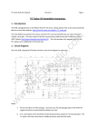
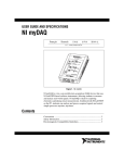
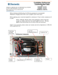
171-0005 Procoin 330 Coin sorter Service Manual Version 1.0 – Jan 2006 INDEX 1. Electric controlling parts…………………………………………………..1 1). Main Board (CPU)…………………………………………………………4 2). Input and Output board (I&O)…………………………..……………….6 3). Amplifier Board (ADC)……………………………………………………8 4) Power supply board (PS)…………………………………………………...9 5). Keypad & LCD Display…………………………………...…..………….10 6). Counting and Detecting Sensor………………..…………………………11 2. Testing functions………………………………………………….……….12 1). Voltage testing…………………………………..……………….………..12 2). Test 1………………………………………………..……………….…….12 3). Accumulated Total Display…………………………….…………….…..13 4). Restoration of Working Parameters…………………………………….13 5). Value Setting…………………………………………….……….……….14 3. Self-study of Coin Parameters………………………….………………..14 4. Mechanical Adjustment………………………………..….…..………….16 5. Error Warning Information……………………………….…..…….…..20 6. Error and Trouble-shooting………………………..…………….….…..20 Enclosure: YFJ-3XX machine’s spare parts drawings and list….…….….22 1. ELECTRIC CONTROLLING PARTS The electric controlling parts of PRC300 series coin rail sorters consist of 5 main parts : ⑴ Main Board(YBJ600CPU-S) ⑵ Input & Output Board(NYFJ400I/O-S) ⑶ Amplifier Board(YFJ500ADC-S) ⑷ Power Supply Board(SGS600P) ⑸ Keypad & LCD Display(YFJ600KDC-S) PRC300 series are installed with the same electric controlling parts. But as they have different channels, their length is different. This version of service manual is covering PRC 330: Front view of the machine PRC330: picture (1) Hopper Keypad and display Foreign coin channel Channels (8pcs) Picture 1 Rear view of the machine PRC330: picture (2) Power supply board Main Board I/O board AMP board Picture 2 The wiring diagram of YFJ-300 series coin rail sorters is as follows:(NEXT PAGE) Picture (3) 1). Main Board The microprocessor of this machine uses W78E58 series. The parallel controlling bus is used as its base. Input and output uses a framework design。 The microprocessor’s working frequency is 16MHZ,using X25045 serial EEPROM to store systematical data under power off,SRAM is 62256(32K byte),DS12887is real time clock, GAL16V8(PLD)is interpretation code,74HC245 is bus driver。The whole process is driven by the signals of clock, and all the operation is performed chronologically strictly. The main board consists of CPU controlling circuit、bus circuit、RS232 communication interface and DIP-8 optional circuit etc. The controlling software is stored in CPU chip and all the working parameters are stored in EEPROM。 Main board: picture (4) CPU Version YBJ600CPU-S Board 8-dip encoder switch Picture 4 Ports on the main board: Main board sockets CN1 40-pin port Remarks Display port,providing working voltage and controlling signals CN2 26-pin port CN3 5-pin port CN4 6-pin port CN5 34-pin port Printer port,providing working voltage and controlling signals Communication interface. Can be connected with RS232 Remote display port(optional) Bus port,connected with ADN board and I&O board Specific functions of the DIP-8 encoder switches: NO ON / OFF 1 2 3 4 FUNCTIONS Factory setting ON To amend values OFF Cannot amend values ON 5 Factory setting OFF ON 6 7 OFF Factory setting ON Self-study, details refer to chapter3 OFF Can’t self-study 8 ON Chinese display OFF English display 2). I&O Board It consists of bus port circuit, solenoid-driving circuit, motor driving circuit, power-regulating circuit, and solenoid-accelerating power circuit. It functions to detect the signals of switches and drive the motors and solenoids. I&O Board: picture (5) Fuse 1 A Lamp L2---24V NYFJ400I/O- Lamp L1----5V Picture 5 Ports on I&O board: I&O board CN1 34-pin port REMARKS Bus port, connected with CPU board and ADC board CN2 2-pin port Connected with coin jam sensor,judging whether coins in the disk are jammed.(See picture 6) CN3 2-pin port Connected with the coin-rejecting solenoid,when foreign coins are detected,CPU sends out signals to reject them. CN4 3-pin port Connected with 220V A.C. CN5 3-pin port Connected disk motor CN6 3-pin port Starting capacitor 1.8UF CN7 4-pin port Pins 1、2&4 are connected with PS Board CH2“1、 2、3”+5V CN8 4-pin port Pins1&3 are connected with PS Board CH3“1、3” +24V CN9 3-pin port Reserved for infrared start-up sensor Coin jam view: picture (6) Coin jam sensor(contact plate) Coin Disk Picture 6 3). AMP Board It consists of AMP board1, AMP board2, AMP board3, AMP board4, compensation circuit, A/D circuit, and power regulation circuit etc. It utilize TLC0820 high-speed AD chip for fast collection of the data of the coins passing by the sensor. AMP Board: picture (7) AMP board1 Potentiometer W3 AMP board2 Potentiometer W2 AMP board4 AMP board3 Potentiometer W1 Compensation board YFJ500ADC-S Datum voltage Potentiometer W4 、W5 、W6 Picture (7) Ports on ADC AMP board: AMP board CN1 port CN2 socket CN3 socket CN4 socket 34-pin CN5 socket 4-pin Remarks Bus socket,to CPU board and I&O board, 3-pin Emitting terminal of the counting and detecting sensor 3-pin Receiving terminal of the counting and detecting sensor 3-pin Pin6 ,+12V ; pin4 ,GND; pin5,-12V Infrared sensor(mounted inside the counting and detecting sensor) CN6 socket 3-pin 78L09 three-phase power-regulator; pin1 +16V; pin2 ,GND; pin3,+9V CN7 socket 3-pin 79L09 three-phase power-regulator; pin1, GND;pin2, - 16V; pin3,-9V There are 4 potentiometers on the ADC AMP board. Voltage adjustment and testing point is as follows Adjust Test point Potentiometer W1 TP10 Potentiometer W2 TP17 Potentiometer W3 TP21 Requirements Observe the wave of the test points with a oscillograph. Make sure that no cut occurs to the sinusoid shape wave. TP26 Potentiometer W4 TPH Potentiometer W5 TPM Potentiometer W6 TPL TP27 Under self-learn mode, adjust the potentiometers. When testing with the smallest size coins, the collected value should be no less than 20. When testing with largest coins ,the collected value should be around 220. A/ D reference voltage 4V 4).Power Supply Board The board functions to transform the output A.C. voltage from the power transformer into D.C voltage through commutation, filtering and regulation. Voltage on each point is as follows: Picture (8) Output 5V Output ±12V Power supply board Fuse 4A Output 24V Picture 8 The power unit is compatible to variable input voltage ,with its range between A.C. 100V to 240V. And the four output groups voltage are respectively:+5V、+12V、-12V、+24V。 Ports on PS board: PORT REMARKS CN1 2-pin Connected with 220V A.C. CN2 6-pin pins1、2&3 are +5V,supplying voltage for integrated circuit blocks;pins4、5&6 are ±12V. CN3 3-pin CN2 Pins 1&3 are +24V 6 pins:Pins1、2&3 are +5V output, Pins 4&5 are -12V output,regulated by three terminal circuit 79L09 to-9V, supplying working voltage for the integrated circuit blocks on the AMP Board. Pins4&6 are +12V output,regulated by three terminal circuit 79L09 to +9V, supplying working voltage for the integrated circuit blocks on the AMP Board. 5). Keypad and Display They mainly consist of bus circuit, contrast adjustment circuit and keypad displaying circuit etc. The display shows the machine’s working status, value sum, and statistics etc. And the operator can select corresponding function according to necessity. It uses 240×64 dots LCD display and provides English operation screen, which can realize the friendly dialogues between operators and machines. Keypad and display: picture (9) LCD display YFJ500KDC-S Keys (12) Picture 9 The contrast potentiometer of the KDC board has been fixed, so when the machine is switched on with SET key pressed, the LCD contrast degree cannot be adjusted. KDC board Connected with 40 poles cable wire CPU board 40 poles cable wire 6). Counting and detecting sensor COINSURE (Picture 10) All the coins passing by the sensor have difference in materials and parameters from each other, which are analyzed and compared by CPU to realize the function of counting and detecting. Counting and detecting sensor (black) Hopper Picture 10 During counting the machine can count coin quantity , sum value and foreign coin sum,and store and print all the data of counted coins. 2.TESTING FUNCTION 1).Test 1 This is mainly to test the condition of two sensors、coin-rejecting solenoid and the disk motor . Operate as follows: Switch on the machine with RESET key pressed and enter test1, the machine displays: TEST 1 S2:1 S3:1 S6:1 S7:1 S4:1 S5:1 Picture 11 S4: Activating sensor S5: 1= coins detected 0= without coins Jam detecting sensor Coin under the counting and detecting sensor , Coin jam:0 0=coin jam 1=no coin jam See Picture (6) S4:0 No coin under the counting and detecting sensor, Press ◄ key,the display shows in its right lower part“REJECT”,with the sound“TA,TA”,which indicates the solenoid works normally,and press start/stop to stop; Press start/stop ,the display shows in its right lower part“MOTOR”,and press start/stop to stop; Press REV key, the display shows in its right lower part “MOTOR R”,and press start/stop to stop; 2.) Test 2 Under Test1 status, press CAS to enter TEST 2 TEST2 Picture(12) This test is mainly to adjust the working voltage of sensor (8pcs) to the best point. Adjust potentiometer W1, W2, W3, respectively until OK is shown. Decrease by turning clockwise, and increase by turning anti-clockwise. 3). Display Accumulated Number When the machine is first switched on, it first carries out a self-check. Then it will display the machine type, software version and accumulated number. 4). Restoration of the Working Parameters Place switch 4 on the DIP-8 encoder switches to ON, press MR key and switch on the machine, it will display “FORMAT?”. Press SET , 15 seconds later it returns to mix count. And the initializing is over. Parameters stored in CPU will be used as working parameters. Then put switch4 to OFF, and turn off the machine. 5). Value Setting Place switch 4 on the DIP-8 encoder switches to ON, then switch on the machine and enter the normal working condition. Press SET to enter the main menu. Select “2. VALUE”. Press SET to enter “value setting”. Press ▲ ▼ to modify the channel number that is flashing. When the value flashes, press M+, MR, PRINT, REV to modify the different digits of the values. Press RESET to clear the value, and/or press SET to save. Press START/STOP to return to normal working condition. 3. SELF-STUDY OF THE COINS’ PARAMETERS The parameters, such as diameter, thickness and material (alloy) of each coin denomination must be stored into the machine. This step is completed by the Self-Study mode as follows: Switch on the machine and the display shows “MIX COUNT’, then press SET to enter “MAIN MENU”. Then by pressing the arrow keys, select “6.LEARN” and press SET to confirm – as shown in picture (18). The display will show the denomination’s parameters such as low frequency, middle frequency and high frequency and the 4th parameter’s maximum and minimum values as well as the difference range. Alternatively directly switch on the machine with START/STOP pressed to enter the SELF-STUDY mode directly. SELF-LEARN 2003.11.20 12׃ 30 Channel:1 Value:0.01 # 92 Parameter 4 # 116 Parameter3 # 114 # 79 Max. .of parameter1 Min. of parameter 1 Parameter 2 Difference range Picture(12) a). Press ▲ ▼ to select the channel. Put between 100-200 coins of each denomination at a time into the hopper and press START/STOP to feed the coins through the machine to allow the Self-Study process to be done for each denomination. b). Press 1000/M+ to save the studied data, when the data flashes it means the data is stored into EEPROM. The result of the self-study of each coin’s parameters are directly related to the accuracy of the machine’s counting and detecting capability. c). Press ◄ to select cyclically print, clear, restore, adjustment or self-learn, and then press SET to confirm. The selection is shown in the upper left area of the display. a. PRINT: to print the parameters of the denomination studied b. CLEAR: to clear the parameters of the denomination studied c. RESTORE: to restore the cleared parameters d. ADJUST: to adjust the parameters of the denomination studied. When selecting adjustment, you can modify the “difference range”. This is done as follows: Press the ▲ ▼. keys to pre-select the “difference range” to be adjusted. The pre-selected range will flash. Then press ► to select the number to be modified. After modification, press SET to save, or press RESET to exit without saving. d). During the process of saving parameters, if the machine finds that two different denominations overlap, it will display the two values. This requires that the parameter study of these two denominations be repeated until the “SAVE” process is OK. * The coin denomination values per channel are fixed - the following is for the EURO coins on the PRC-420: TABLE (1): VALUE 0.01 CHANNEL FOREIGN 1 0.02 0.1 0.2 0.05 1.00 0.50 2.00 2 3 4 5 6 7 8 COIN BOX Table (1) (Euro) It could be possible that 2 different issues of a denomination may be required to be counted and/or split. In this case, the parameters of one of these issues can be stored under channel 9 4. MECHANICAL ADJUSTMENT 4.1 Drive disk(66)and hopper(26) Adjustment:when mounting hoppers、ensure the left side gap between the hopper (26) and the disk(66) Note:If the surface of the centering disk is higher than that of the driver disk , this will slow down the sorting speed,and easily causes coin jams. In the middle should be adjusted to be 5.7mm with a 5.7mm gauge(Fig.1). There is a 1~2mm adjustable gap between the hopper and hopper spacer. When coin jam occurs ,the hopper can be moved outward 1~2mm automatically to remove coin jams by itself.(Fig. 2) 66 2mm 26 (Fig .1) (Fig. 2) If the gap is not appropriately adjusted; the machine cannot automatically remove the coin jams. 4.2 Drive disk(31)and centering disk(32)adjustment Belt wheel (67) must be threaded tightly by the drive disk( 66) screw S1 ,and the surface of the centering disk (65) must be even to or lower than the surface of the drive disk belt wheel. S1 67 (Fig . 3) 66 65 (Fig. 4) Note:If the surface of the centering disk is higher than that of the driver disk , this will slow down the sorting speed,and easily causes coin jams. 4.3 Adjustments of Rail and Back up Plate for Rail Adjustment:The rail and back up plate must be level off. Adjust the flatness of the rail by the screw wholes on it。The back up plate must be flat and straight,and adjust it with the suck-head screw。 phenomena:Rail and back up plate must be flat and straight. If not, when coins roll down, they may jump or roll off the rail, which will cause error counting. 4.4 Limit block adjustment 1.The distance between the front sharp angle of the triangle limit block (23 )and the surface of the rail ( 24) should be equivalent to the diameter of the biggest coin plus 2mm(Fig.5),the distance between the side of the contact plate(27 ) and the sliding plate should be the thickness of the thickest coin plus 0.5mm(Fig.6). 24 23 L1 H1 (Fig. 5) (Fig.6) 27 2.Deflector(40)height H2(between deflector and the rail),should be equivalent to the diameter of the corresponding coin denomination to deflect the coin into the channel . If the contact plate is mounted improperly, two overlapping coins may pass on to the rail. If the limit block is amounted improperly, three coins may pass on to the rail simultaneously, which will cause error counting. If the deflector is mounted too high, it will lose its function of guiding coins. If it is mounted too low, coin jams will occur. 4.5 Adjustment of Motor Belt Adjustment:Belt(68) should not be too loose. If the belt is too loose, loosen the four screws (72)in the motor to move the motor downward. (Fig.7) phenomena:If belt(68 ) is too loose,it will slide and slow down the sorting speed。 Note:1、The belt wheel of the motor and the belt wheel on the disk must be in the same plane. 2、After mounting the cover,it should not prevent the movement of the hopper. 68 72 (Fig. 7) 5. ERROR INFORMATION Errors During Sorting, Error displayed Coin jam! Reason Correction Short circuit between jam Remove the coin and press RESET sensor and rail Coin under sensor 1 ! There is coin under counting and detecting Remove the coin and press RESET sensor 1. Empty the drawer,press START Foreign coins reach 200 Box full! pcs 2.Press ▲ and RESET simultaneously to clear foreign coins number only. BATCH OK! Batch number is reached Press RESET 6. ERRORS AND TROUBLE SHOOTING 1). Hesitant Coin Transportation After the machine is used for a period of time or it is heavily used every day, some parts may suffer from normal wear and tear., which will influence the normal counting and detecting accuracy of the machine, so the corresponding parts should be changed. Details refer to Chapter5. 2). Parameters Adjustment If the machine works abnormally or wrongly rejects coins, especially after any mechanical adjustment has been carried out, then the coin parameters should be re-Studied/learnt.- refer to “3. Self-learn of the parameters of coins” 3). Display Panel Damaged If the display panel displays characters lacking strokes or unknown marks, please check whether the 40-pin power line is in good condition or change the display panel. 4) Sensors Damaged Over time, some of machine’s sensors may age. The machine will warn with errors messages. The condition of the sensors can be tested in test1. For the specific test, please refer to “2.test function”. 5). Circuit Board Damaged ① Fuse melts due to short circuit. I/O board fuse: 1pc F1-------1A disk motor Power fuse: 1pc 3.15A------220V A.C. INPUT Power board fuse: 1pc F1------4A AND board fuse: 2pc F1------1A (regulated) 9V F2------1A (regulated)-9V ② CN3(24V)on power supply board can not be tested:PS board PKE200 orTOP227 is damaged. CN2(5V)on power supply board can not be tested:PS board TL431 is damaged。 ③ TPH、TPM、TPL voltage on ADC board cannot be tested : L1 lamp AND is off,78L09 is damaged。 7). Motor Damaged Motor does not rotate:capacitor malfunctions or fuse melts;Or the failure of its own. Change corresponding components according to situation or error information. If there is any problem that cannot be handled by yourself, please contact the local distributor. 7. Enclosure: YFJ-3XX Machine’s Spare Parts Drawings and List Rail Coin Sorter Parts List NO. DISCRIPTION QTY 1 Rubber pad 4 4.75 2 Base plate 1 250.00 3 Suspect coin box 1 30.00 4 Suspect coin channel 1 32.00 5 Left frame 1 110.00 6 Side plate 1 12.00 7 Ground connector 2 2.00 8 Hexagon bolt 2 0.70 9 Lock nut 5 1.50 10 Coin scraper 8 5.00 11 Side plate (left) 1 5.00 12 Back plate 1 14.00 13 Guide rail 1 80.00 14 Back up plate for rail 1 100.00 15 Coin guide plate 1 1.00 1 3.00 16 Baffle plate(1) UNIT PRICE(¥) 17 Suspect coin box 1 18.60 18 Sunk-head screw M3 1 0.13 19 Sensor 1 3.00 20 Plastic plate (big) 1 4.50 REMARK 21 Plastic plate (small) 1 6.00 22 Coin exit channel 1 120.00 23 Limit block for coin dia. 8 5.00 25 Feed plate for rail 1 100.00 26 Back up plate 1 54.00 1 5.00 24 27 Round channel(2) 28 Disk support frame 1 36.70 29 Belt wheel (big) 1 37.50 30 Oil bush 2 1.00 31 Drive disk 1 111.50 32 Centering disk 1 24.50 33 Contact plate 1 2.50 34 Hopper 1 150.00 35 Compression spring 1 0.60 36 Aluminum tube 1 2.00 37 Hexagon head bolt 1 0.70 38 Hinge 1 20.10 39 Pad hinge 1 20.00 40 Upper plate 1 126.00 41 Drawer 9 25.50 42 Lower cover 1 1 32.00 43 Lower cover 2 1 1.06 44 Belt wheel (small) 1 18.00 45 Motor feet 4 1.20 46 Motor 1 570.00 47 Power board 1 408.00 48 Socket 1 60.00 49 Switch 1 11.40 50 Socket holder 1 12.00 51 Fuse holder 1 8.40 52 Aluminum fixed plate 1 6.00 53 CPU board 1 115.72 54 Aluminum back plate 1 46.00 55 Right frame 1 114.00 56 A/D board 1 397.69 57 Aluminum slope bar 1 13.50 58 Belt 1 24.00 59 Shaft 1 8.70 60 Hopper cover 1 25.50 61 Hinge 2 5.60 62 Hinge 2 5.60 63 Plastic door 1 1.02 64 Cover 1 542.00 65 Display panel 1 100.91 66 Rear cover 1 11.84 67 Fixture plate 1 50 68 PS board holder 1 11.98 69 I/O board 1 193.71 70 Fixture strip 1 1 7.31 71 Fixture strip 2 1 7.31 8. Electronic Boards Layout. Coin-rejecting solenoid Disk pulse sensor Magnet safty switch Micro-switch Hopper sensor Coin -rejecting activating sensor Disk sensor Case full sensor Coin-stopping solenoid YFJJAM°å 2 CN4 (IO-CN4) CN2 (IO-CN2) CN5 8 2 CN6 7 1 4 3 3 2 5 4 1 2 Ï 1 6 5 4 3 2 6 2 1 5 2 3 2 1 1 2 8 2 6 7 1 5 4 2 2 3 1 1 ÉÏ 6 1 CN2 CN7 (IO-CN5) (IO-CN7) I&O Board 5uF Coin-climbing motor Coin-climbing motor capacitor Hopper motor High voltage switch Disk motor capacitor 2 1 6 (IO-CN17) 5 4 3 2 1 2 3 220V AC power Disk motor L PE N Out put 220V AC voltage Picture(6) Wiring diagram of I/O BOARD PS-CN3 35V AC 1 2 3 Connector +15V +5V +24V 1.8uF CN17 (IO-CN16) 1 3 2 1 3 3 2 1 M M CN16 (IO-CN14) 2 1 M CN14 CN13 (IO-CN13) 1 CN12 (IO-CN12) 3 2 1 3 2 1 3 2 (IO-CN11) 1 (IO-CN10) 6 (IO-CN9) 5 CN11 (IO-CN8) 4 CN10 3 CN9 2 1 F504-X0200-00 CN8 Solenoid accelerating-power 1 2 3 4 5 6 7 8 RST C2 30P VCC VCC 35 44 6 5 2 SCK SI SO 1 VCC /WP RST GND /CS U6 X25045 8 3 7 4 R1 10K X2 GND VCC P10 P11 P12 P13 P14 P15 P16 P17 EA/VP VCC 2 3 4 5 6 7 8 9 P10 P11 P12 P13 P14 P15 P16 P17 Q1 T0 RXD TXD VCC 16 11 13 T0 RXD TXD 3 18 4 17 7 14 8 13 1 OE LE 2 3 4 5 6 7 8 9 A8 A9 A10 A11 A12 A13 A14 A15 ALE RST INT0 INT1 T1 Q0 Q7 Q1 Q6 Q2 Q5 Q3 Q4 A0 A1 A2 A3 A4 A5 A6 A7 2 19 5 16 6 15 9 12 11 A0 A1 A2 A3 A4 A5 A6 A7 A8 A9 A10 A11 A12 A13 A14 /WR /RD ALE 10 9 8 7 6 5 4 3 25 24 21 23 2 26 1 27 22 11 12 13 15 16 17 18 19 D0 D1 D2 D3 D4 D5 D6 D7 D0 D1 D2 D3 D4 D5 D6 D7 /RD /WR ALE 17 15 14 1 12 1 4 5 6 7 8 9 10 11 D0 D1 D2 D3 D4 D5 D6 D7 MOT VSS D0 D1 D2 D3 D4 D5 D6 D7 2 3 4 5 6 7 8 9 19 21 /IRQ SQW RN1 VCC 13 O5 24 18 VCC 20 /CS 1 VDD C7 VCC 0.01U R6 2 3 4 5 6 7 8 9 A0 A1 A2 A3 A4 A5 A6 A7 /RST L1 R4 1K RN4 O4 /CE 10K 1 VCC RN3 OE CLK U8 74HC374 2 19 5 16 6 15 9 12 Q0 Q7 Q1 Q6 Q2 Q5 Q3 Q4 D0 D7 D1 D6 D2 D5 D3 D4 OE CLK 3 18 4 17 7 14 8 13 D0 D1 D2 D3 D4 D5 D6 D7 1 11 RST O1 3 18 4 17 7 14 8 13 D0 D1 D2 D3 D4 D5 D6 D7 1 11 RST O7 1K Q2 9012 R5 3K BZ1 5V Q5 O2 O3 19 1 CN1 A0 A1 A2 A3 A4 A5 A6 A7 2 3 4 5 6 7 8 9 D0" D1" D2" D3" D4" D5" D6" D7" O8 O7 O6 O5 O4 O3 O2 O1 12 13 O8 O7 14 15 16 17 18 19 O6 O5 O4 O3 O2 O1 /RD /WR INT0 INT1 T1 2 3 4 5 6 7 8 9 VCC VCC D5" 18 17 16 15 14 13 12 11 U15 74HC245 B0 B1 B2 B3 B4 B5 B6 B7 D7" A0 A1 A2 A3 A4 A5 A6 A7 2 3 4 5 6 7 8 9 A15" A14" A13" A12" A11" A10" A1" A0" C2- A14" A13" A12" A11" 1 U7 74HC245 10K*8 E DIR 1 A10" U16 74HC245 VCC 1 2 3 4 5 6 7 8 9 C1- A15" SW1 1 2 3 4 5 6 7 8 5 U9 ICL232 16 15 14 13 12 11 10 9 2 3 4 5 6 7 8 9 A0 A1 A2 A3 A4 A5 A6 A7 E B0 B1 B2 B3 B4 B5 B6 B7 19 18 17 16 15 14 13 12 11 O8 D0 D1 D2 D3 D4 D5 D6 D7 /RD /WR RST 18 17 16 15 14 13 12 11 19 B0 B1 B2 B3 B4 B5 B6 B7 A0" A0 A1 A2 A3 A4 A5 A6 A7 E DIR 2 3 4 5 6 7 8 9 /RD" /WR" RST" /RD" /WR" RST" 1 2 3 4 5 6 7 8 9 10 11 12 13 14 15 16 17 18 19 20 21 22 23 24 25 26 27 28 29 30 31 32 33 34 35 36 37 38 39 40 D0 D1 D2 D3 D4 D5 D6 D7 2 3 4 5 6 7 8 9 O6 /RD 19 1 A15 A14 A13 A12 A11 A10 A1 A0 2 3 4 5 6 7 8 9 1 CN5 1 2 3 4 5 6 7 8 9 10 11 12 13 14 15 16 17 18 19 20 21 22 23 24 25 26 27 28 29 30 31 32 33 34 D0' D1' D2' D3' D4' D5' D6' E DIR U12 74HC245 A0 A1 A2 A3 A4 A5 A6 A7 DIR D7' A15' A14' 18 17 16 15 14 13 12 11 B0 B1 B2 B3 B4 B5 B6 B7 A15' A14' A13' A12' A11' A10' A1' A0' A13' A12' A11' A10' A1' A0' /RD' /WR' INT0' 19 E INT1' T1' RST' A2' U13 74HC245 2 3 16 15 14 7 8 9 /RD /WR INT0 INT1 T1 RST A2 VCC C26 100U/16V 1 D0' D1' D2' D3' D4' D5' D6' D7' 18 17 16 15 14 13 12 11 B0 B1 B2 B3 B4 B5 B6 B7 VCC 1 A0 A1 B2 B3 B4 A5 A6 A7 18 17 4 5 6 13 12 11 B0 B1 A2 A3 A4 B5 B6 B7 DIR /RD' /WR' INT0' INT1' T1' RST' A2' B VCC 19 E VCC 8 13 7 14 15 (CTS) (RXD) (RTS) (TXD) D3" D6" A15 A14 A13 A12 A11 A10 A1 A0 19 DIR 2 4 C4 22U /16V V+ C2+ D2" RN2 C5 22U/16V R 2I R 1I T 2O T 1O G ND 3 VC1+ D1" D4" E DIR VCC U10 GAL16V8 I1 I2 I3 I4 I5 I6 I7 I8 CLK OE 2 3 4 5 6 7 8 9 1 11 /RD /WR A15 A14 A13 A12 A11 A10 RST D0" A1" 9 12 10 11 16 C6 22U/16V C3 22U /16V 5 6PIN RS232 PORT 4 3 2 1 18 17 16 15 14 13 12 11 RN5 6 1 CN3 D0 D1 D2 D3 D4 D5 D6 D7 U11 74HC245 A0 A1 A2 A3 A4 A5 A6 A7 I/O PO RT 5K1 R7 D0 D7 D1 D6 D2 D5 D3 D4 U14 74HC245 B0 B1 B2 B3 B4 B5 B6 B7 34PIN -DC 2 R2 P15 2 19 5 16 6 15 9 12 VCC 40PIN- DC2 P14 P15 T0 Q1 Q2 Q3 Q4 Q5 U17 74HC374 Q0 Q7 Q1 Q6 Q2 Q5 Q3 Q4 DISPLAY PORT(1) (CLK) (BUSY) (SEL) C R8 5K1 R3 10K R2O R1O T2I T1I V CC 26PIN -D C2 PRINT PORT 1 21 25 3 4 5 6 7 8 9 10 11 12 13 14 15 16 17 18 19 20 22 23 24 2 26 9012 VCC Q3 Q4 TXD P17 RXD P16 CN2 B Q1 P13 P10 Q2 P11 1 (KEYIN) (SCL) (CS) (SDA) 10K *8 6PIN 2 3 4 5 6 DISPLAY PORT( 2) CN4 C D 10K*8 20 22 D0 D1 D2 D3 D4 D5 D6 D7 A8 A9 A10 A11 A12 A13 A14 A15 /WR /RD 43 42 41 40 39 38 37 36 24 25 26 27 28 29 30 31 18 19 32 33 10 14 15 17 U5 DS12887 DS R/W AS 1 P00 P01 P02 P03 P04 P05 P06 P07 P20 P21 P22 P23 P24 P25 P26 P27 WR RD PSEN ALE/P RESET INT0 INT1 T1 U4 62256 A0 A1 A2 A3 A4 A5 A6 A7 A8 A9 A10 A11 A12 A13 A14 WE OE 10K *8 X1 HD1 16M U2 74HC373 D0 D7 D1 D6 D2 D5 D3 D4 10K*8 D NC NC NC NC U1 AT89C52 21 1 12 23 34 VCC C1 30P C28 C29 C24 C27 22U/16V VCC VCC C25 0.01U C32 22U/16V C11 A 22U/16V VCC C23 0.01U C12 0.01U C13 0.01U C14 0.01U C15 0.01U C16 0.01U C17 0.01U C18 0.01U C19 0.01U C20 0.01U C21 0.01U C22 0.01U C9 0.01U C10 0.01U C30 22U/16V C31 22U/16V 22U/16V YBJ600CPU-S Title 0.01U Size A 220U/16V Number Revision A3 Date: File: 1 2 3 4 5 6 26-May-2005 E:\99\Ybj600.ddb 7 Sheet of Drawn By: 1 1 8 D0" D1" D2" U2 74HC245 A7 A6 A5 A4 A3 A2 A1 A0 B7 B6 B5 B4 B3 B2 B1 B0 DIR D3" E 11 12 13 14 15 16 17 18 1 D0 D1 D2 D3 D4 D5 D6 D7 /RD 19 O2 D0 D1 D2 D3 D4 D5 D6 D7 9 8 7 6 5 4 3 2 O3 19 D0 D1 D2 D3 D4 D5 D6 D7 8 13 7 14 4 17 3 18 RST O5 1 11 5 U1 74HC245 A7 A6 A5 A4 A3 A2 A1 A0 B7 B6 B5 B4 B3 B2 B1 B0 E DIR 11 12 13 14 15 16 17 18 6 PB7 PB6 PB5 PB4 PB3 PB2 PB1 PB0 10K*8 TO LED D R1 VCC 6.8/0.5W 1 D4" P B5 P B4 P B3 P B2 D6" P B1 P B0 D5" D7" A15" A14" A13" A11" A15" A14" A13" A12" A11" A10" A1" A0" A10" A1" A0" /RD" 4 3 2 5 6 7 8 9 /WR" RST" 1 U3 74HC245 A2 A1 A0 A3 A4 A5 A6 A7 DIR B2 B1 B0 B3 B4 B5 B6 B7 E 16 17 18 15 14 13 12 11 A15 A14 A13 A12 A11 A10 A1 A0 U8 74HC374 D3 D4 D2 D5 D1 D6 D0 D7 Q3 Q4 Q2 Q5 Q1 Q6 Q0 Q7 9 12 6 15 5 16 2 19 S7 12*12·½¼ü S8 12*12·½¼ü S9 12*12·½¼ü S10 12*12·½¼ü S11 12*12·½¼ü S12 12*12·½¼ü S1 12*12·½¼ü S2 12*12·½¼ü S3 12*12·½¼ü S4 12*12·½¼ü S5 12*12·½¼ü S6 12*12·½¼ü D2 1N4148 OE CLK 19 VCC C4 0.01U B /RD" /WR" RST" 4 3 2 5 6 7 8 9 VCC C9 0.01U C14 0.01U 1 U4 74HC245 A2 A1 A0 A3 A4 A5 A6 A7 DIR B2 B1 B0 B3 B4 B5 B6 B7 E 16 17 18 15 14 13 12 11 /RD /WR RST A15 A14 A13 A12 A11 A10 /RD /WR 2 3 4 5 6 7 8 9 RST 1 11 U5 GAL16V8 I1 I2 I3 I4 I5 I6 I7 I8 R4 1K O1 O2 O3 O4 O5 O6 O7 O8 19 18 17 16 15 14 13 12 R5 1K O1 O2 O3 O4 O5 O6 O7 O8 VCC /CS /INC U/D VSS 8 3 5 6 VCC VH VW VL O1 D0 D1 D2 D3 D4 D5 D6 D7 R3 20k C19 1000P Q1 9013 VCC C13 10U/16V C11 0.1U VCC W1 5K 22U/16V C10 C7 0.01U C8 0.01U B CN2.19=GND 19 VCC 1 2 3 4 5 6 7 8 9 10 11 12 13 14 15 16 17 18 19 20 /WR /RD O4 A0 R2 0 U7 X9313W 7 1 2 4 C18 510P CLK OE VCC C6 0.01U CN2 VCC VCC C3 22U/16V C D1 1N4148 LC D POR T A12" VCC C5 0.01U 8 CN3 2PIN-2.54 RN1 1 VCC 7 20 PI N-DC 2 40 PI N-DC 2 T O YB J600 CP U CN1 C 1 2 3 4 5 6 7 8 9 10 11 12 13 14 15 16 17 18 19 20 21 22 23 24 25 26 27 28 29 30 31 32 33 34 35 36 37 38 39 40 9 8 7 6 5 4 3 2 4 1 2 D0" D1" D2" D3" D4" D5" D6" D7" CN1 D 3 2 3 4 5 6 7 8 9 2 PB 0 PB 1 PB 2 PB 3 PB 4 PB 5 PB 6 PB 7 1 10U/16V 2 1 4 3 U6 ICL7660 CP+ N.C CPGND V+ OSC LV VO 8 7 6 5 C15 10U/16V 2 1 4 3 C12 10U/16V A U9 ICL7660 CP+ N.C CPGND V+ OSC LV VO C1 C2 0.01U 8 7 6 5 C17 0.01U C16 10U/16V A ±ê¼Ç ÊýÁ¿ ¸ü¸Äµ¥ºÅ Éè ¼Æ Éó ºË ±ê×¼»¯ Åú ×¼ 1 2 3 4 5 6 °ü×°»ú ¼üÅÌÏÔʾ°å £¨±íÌù°å£© 7 Ç©Ãû YBJ600KDC-S ½×¶Î±ê¼Ç µÚ 1 ÕÅ ÉÙ Ê¿ SOUTH 8 ¹² ÈÕÆÚ 1 ÕÅ 1 2 3 4 5 6 7 8 D D yfjADC-1 yfjADC-S.S01 yfjADC-3 yfjADC-S.S03 FQ CY FQ CY HIN HOUT MIN MOUT LIN LOUT I/O BUS INT0 C HIN HOUT MIN MOUT LIN LOUT I/O BUS C INT0 yfjADC-2 yfjADC-S.S02 yfjADC-4 yfjADC-S.S04 FQ CY B HIN HOUT MIN MOUT LIN LOUT I/O BUS B I/O BUS INT0 A A ±ê¼Ç ÊýÁ¿ Éè ¼Æ Éó ºË ±ê×¼»¯ Åú ×¼ 1 2 3 4 5 6 Ä£Äâ´¦Àí°å £¨±íÌù°å£© 7 ¸ü¸Äµ¥ºÅ Ç©Ãû ÈÕÆÚ YFJ500ADC-S ½×¶Î±ê¼Ç µÚ 1 ÕÅ ÉÙ Ê¿ SOUTH 8 ¹² 5 ÕÅ 1 2 3 D D0' D1' D2' D3' D4' D5' D6' D7' 2 3 4 5 6 7 8 9 U1 74HC245 A0 A1 A2 A3 A4 A5 A6 A7 4 5 6 7 D B0 B1 B2 B3 B4 B5 B6 B7 DIR E 18 17 16 15 14 13 12 11 D0 D1 D2 D3 D4 D5 D6 D7 1 19 /RD O1 VCC C1 22U/16V C2 0.01U C3 0.01U C4 0.01U C5 0.01U C6 0.01U VCC D0 D1 D2 D3 D4 D5 D6 D7 D2' D3' D4' D5' D6' A15' A14' A13' A12' A11' A10' A1' A0' D7' A15' A14' A13' A12' A11' 2 3 4 5 6 7 8 9 A10' A1' A0' A0 A1 A2 A3 A4 A5 A6 A7 DIR B0 B1 B2 B3 B4 B5 B6 B7 E 18 17 16 15 14 13 12 11 A15 A14 A13 A12 A11 A10 A1 A0 C RN1 VCC 19 /RD' /WR' INT0' VCC RST' A2' /RD' /WR' INT0' RST' A2' 2 3 16 15 14 7 8 9 1 U3 74HC245 A0 A1 B2 B3 B4 A5 A6 A7 DIR B0 B1 A2 A3 A4 B5 B6 B7 E 18 17 4 5 6 13 12 11 2 3 4 5 6 7 8 9 RST 1 11 U4 GAL16V8 I1 I2 I3 I4 I5 I6 I7 I8 O1 O2 O3 O4 O5 O6 O7 O8 19 18 17 16 15 14 13 12 A15 A14 A13 A12 A11 A10 A1 A0 O1 O2 O3 O4 O5 O6 O7 O8 2 3 4 5 6 7 8 9 RN2 CLK OE B VCC /RD /WR INT0 INT1 T1 RST A2 1 VCC A15 A14 A13 A12 A11 A10 /RD /WR 10 K* 8 1 1 U2 74HC245 2 3 4 5 6 7 8 9 1 0K* 8 D0' D1' /RD /WR INT0 INT1 T1 RST A2 19 2 3 4 5 6 7 8 9 1 0K*8 3 4PIN TO YBJ60 0CP U CN5 B 1 2 3 4 5 6 7 8 9 10 11 12 13 14 15 16 17 18 19 20 21 22 23 24 25 26 27 28 29 30 31 32 33 34 1 CN1 C 8 RN3 VCC I/O BUS A A ±ê¼Ç ÊýÁ¿ Éè ¼Æ Éó ºË ±ê×¼»¯ Åú ×¼ 1 2 3 4 5 6 Ä£Äâ´¦Àí°å £¨±íÌù°å£© 7 ¸ü¸Äµ¥ºÅ Ç©Ãû YFJ500ADC-S ½×¶Î±ê¼Ç µÚ 2 ÕÅ ÉÙ Ê¿ SOUTH 8 ¹² ÈÕÆÚ 5 ÕÅ 3 4 6 +9 C14 0.01U C15 0.01U C16 22U/16V C17 0.01U C18 22U/16V RST 6 TJ1 C10 1200P C10' 2200P C D7 O8 2 3 4 5 6 7 8 9 19 1 A0 A1 A2 A3 A4 A5 A6 A7 3 18 4 7 13 8 14 17 18 17 16 15 14 13 12 11 RST O2 1 11 FK3 FK2 FK1 CM 10 CL TJ5 +9 VCC U7 74HC374 21 20 19 18 8 15 14 17 U18 7 Q0 Q7 Q1 Q2 Q4 Q3 Q5 Q6 2 19 5 6 12 9 15 16 CSH CSM CSL /INC U/D CYA A0 A1 A2 25 24 23 O6 22 O7 9 6 10 OE CLK 17 13 12 R3 200 ADC0808CCV msb2-1 2-2 2-3 2-4 2-5 2-6 2-7 lsb2-8 IN-0 IN-1 IN-2 IN-3 IN-4 EOC IN-5 ADD-A ADD-B ADD-C IN-6 IN-7 ALE ENABLE START CLOCK +9 ref(-) ref(+) D7 BAT42 D8 BAT42 C73 0.01U C74 0.01U C75 0.01U I/O BUS 2 3 28 1 2 4 TP27 5 16 +9 12 U16A 8 1 4 3 6 9 11 12 13 14 15 16 CSH CSM CSL /INC U/D CYA 3 C68 22U/16V R28 U21D 9 5 74HC14 74HC14 U21E 8 YFJ500ADJ-S HADJ MADJ LADJ CSH CSM CSL /INC U/D CYA HIN HOUT MIN MOUT LIN LOUT +9V GND -9V VCC 1 2 4 5 7 8 17 18 19 20 2 3 11 +9 TL431 R27 R26 6k8 2K +9 12 A 74HC14 ±ê¼Ç ÊýÁ¿ ¸ü¸Äµ¥ºÅ 5 1 B U21F 10 13 74HC14 -9 C70 220P 4 (SEE PAGE 3) C69 0.01U 6 Ç©Ãû ÈÕÆÚ YFJ500ADC-S Éè ¼Æ Éó ºË ±ê×¼»¯ Åú ×¼ 1 HIN HOUT MIN MOUT LIN LOUT VCC 2 4 U21C U19 3 C71 0.01U R29 10K 6 C20 0.01U 27 74HC14 C76 0.01U C55 0.01U 26 3k A C78 0.01U C77 0.01U D6 BAT42 U21B 74HC14 VCC HIGHT= (100T) C U20 U21A 1 LOW=(120T) -9 VCC CY FQ CN2 3PIN -9 LM358 (SEE PAGE 3) 1 2 3 Q2 2SB772 R5 10K RFK 33K TJ43 R8 4.7/0.25W C12 100P D2 1N4148 TP3 TP2 TP1 -9 TJ44 C11'' D0 D1 D2 D3 D4 D5 D6 D7 9 8 1 TP4 TJ6 0.022U E DIR D0 D7 D1 D2 D4 D3 D5 D6 CH 0.01U B0 B1 B2 B3 B4 B5 B6 B7 10K D0 D1 D2 D3 D4 D5 D6 D7 FLI TPL TPM TPH TJ4 C11' R30 B 7 TJ3 C11 2200P U22 74HC245 2 TJ2 N.C 18 OUT FMI 11 220P C9' FHI VSS COUT C9 12 3 GND COUT 16 15 14 13 12 11 10 9 D1 1N4148 16 9 1 2 3 4 5 6 7 8 VDD 10 JP1 7 5 4 6 14 13 15 1 2 3 Q4 Q5 Q6 Q7 Q8 Q9 Q10 Q12 Q13 Q14 R1 1M U6 YFJ500SENT-S 15 HD1 8M C8 30P CIN Q1 2SD882 R2 200 TP26 14 11 U5 74HC4060 D R4 10K C19 0.01U -9 C7 30P 8 +9 D C13 22U/16V 7 ANALOG OUTPUT S VCC 5 R6 1 0 /0 .2 5W 2 R7 1 0/0 .2 5W 1 Ä£Äâ´¦Àí°å £¨±íÌù°å£© 7 ½×¶Î±ê¼Ç µÚ 3 ÕÅ ÉÙ Ê¿ SOUTH 8 ¹² 5 ÕÅ 5 6 TJ7 CN3 3PIN ANALOG INP UTS D LOW=(120T) HIGHT= (140T) R12 100K 2 R10 10k 1 2 3 -9 4 1 8 3 6 5 C21 TJ9 +9 TP6 C22 TJ11 TP5 +9 1 FIN1 2 5 FIN2 TP1 3 FIN3 4 FIN4 22 GND 75P TJ12 C23 22P C23' N.C TJ13 TJ14 C24 22P -9 HOUT U10 YFJ500HAMP-S 16 W3 15 W2 14 W1 13 TP4 12 WX 11 TP3 FIN5 FIN6 TP5 TP2 9 10 17 8 D 100K TP8 TJ15 TP10 TP7 TJ16 C26 30P TJ17 C25 30P C30' 75P C30 100P TJ26 TP13 C31' 200P C31 150P TJ29 TJ30 FIN3 TP2 4 FIN4 10 WX1 W1 TP6 19 18 TP3 WX2 TP5 17 16 FIN5 FIN7 FIN8 14 15 11 12 FIN6 TP4 C32 150P C32' 200P B 25 24 23 22 21 20 6 7 TJ28 28 3 R13 5K6 TJ27 VSS OUT CY FQ TP7 W3 W2 TJ45 TJ35 TJ36 C35'' 3300P C35' 1800P TJ46 TJ37 -9 TP17 MOUT MIN 50K (SEE PAGE 2) C36'' 3300P TP18 TP16 W2 TJ38 C36' 1800P TJ31 13 TP14 TJ33 R14 TJ32 C34' 75P C34 100P 1 C36 470P TP15 TJ34 C33 100P TJ47 C33' 75P TJ39 C37'' 1800P 2 3 15K TP19 U12 YFJ500LAMP-S FIN1 FIN2 TP1 4 WX1 5 TP2 7 FIN4 C37' 1500P +9 +9 C43 0.01U C44 0.01U C50 22U/16V C48 0.01U C49 0.01U +9 FIN3 6 R15 2K TP21 LOUT (SEE PAGE 2) LIN TP25 W3 100K TJ41 C38' 1500P C47 0.01U C38 300P D4 1N4148 TP20 1 12 TJ48 20 7 C65 0.01u VCC 11 10 18 19 9 C38'' 1800P U16B LM358 7 6 D5 1N4148 +9 1 12 R31 2K U25B LM358 7 6 5 W5 10K R33 2K U25A LM358 1 2 3 W6 10K TP-L VCC C52 0.01U C53 0.01U C54 0.01U R16 3K3 U8 TL431 C41 C72 0.01U 0.01U R32 3K3 U23 TL431 C79 0.01U C80 0.01U R34 3K3 U24 TL431 20 7 11 10 18 19 9 +9 C51 0.01U C 2 3 4 5 14 15 16 17 13 6 8 D0 D1 D2 D3 D4 D5 D6 D7 O3 /WR /RD U14 TLC0820A AIN D0 RE+ D1 D2 VCC D3 MOD D4 D5 RED6 GND D7 /OF /CS NC /WR /IT /RD 2 3 4 5 14 15 16 17 13 6 8 D0 D1 D2 D3 D4 D5 D6 D7 O4 /WR /RD U15 TLC0820A AIN D0 RE+ D1 D2 VCC D3 MOD D4 D5 RED6 GND D7 /OF /CS NC /WR /IT /RD 2 3 4 5 14 15 16 17 13 6 8 D0 D1 D2 D3 D4 D5 D6 D7 O5 /WR /RD B VCC VCC C46 0.01U TJ42 I/O BUS U13 TLC0820A AIN D0 RE+ D1 D2 VCC D3 MOD D4 D5 RED6 GND D7 /OF /CS NC /WR /IT /RD VCC TP-M W4 10K A C45 22U/16V WX2 TP3 9 8 +9 5 -9 W1 TP4 13 12 11 10 18 19 9 4 C42 0.01U 19 18 17 16 15 14 20 7 C25' N.C TP-H +9 C40 22U/16V OUT CY FQ TP5 W3 W2 -9 C39 22U/16V VCC VCC C66 0.01u TJ40 C37 300P 1 12 C64 0.01u C35 470P 8 TJ25 TP1 27 VSS TJ24 C29 100P FIN2 5 GND D3 1N4148 +9 GND C29' 75P 2 26 22 C28 150P TP11 TJ23 VDD VDD 1 U11 YFJ500MAMP-S FIN1 21 TJ22 C28' 220P TP12 150P 20 C27 C26' N.C TJ18 VCC C TP9 W1 (SEE PAGE 2) CY FQ TJ20 C27' 220P TJ21 (SEE PAGE 2) HIN 19 18 20 C24' N.C TJ19 75P TJ10 C22' N.C U9A TLE2082 R11 100K U9B TLE2082 7 8 TJ8 C21' N.C 21 R9 10k 7 23 4 VSS 3 VDD 2 CY FQ OUT 1 C81 C82 0.01U 0.01U A ±ê¼Ç ÊýÁ¿ ¸ü¸Äµ¥ºÅ 1 2 3 4 5 2 6 Ç©Ãû YFJ500ADC-S Éè ¼Æ Éó ºË ±ê×¼»¯ Åú ×¼ -9 Ä£Äâ´¦Àí°å £¨±íÌù°å£© 7 ½×¶Î±ê¼Ç µÚ 4 ÕÅ ÉÙ Ê¿ SOUTH 8 ÈÕÆÚ ¹² 5 ÕÅ 1 2 3 4 5 CN6 2.54-3P 1 2 3 D F1 1A 6 7 8 D (7809) TP23 +9 R17 1K5 TO TRANSFORME R C56 1000U/25V CN4 3PIN C58 0.01U C60 0.01U C62 22U/16V L1 BG1 KBJ210 1 2 3 R18 1K5 C57 1000U/25V C59 0.01U C61 0.01U C63 22U/16V L2 F2 1A C 1 2 3 C CN7 2.54-3P (7909) -9 TP24 +9 R22 10K B CN5 4PIN 1 2 3 4 R19 1K U17A LM393 3 R21 1K 1 2 INT0 5 (SEE PAGE 1) 6 U17B LM393 7 B 4 START SENSOR 8 R20 20K C67 1000P R24 680 R25 100K R23 20K +9 A A ±ê¼Ç ÊýÁ¿ 1 2 3 4 5 3 6 ¸ü¸Äµ¥ºÅ Ç©Ãû YFJ500ADC-S Éè ¼Æ Éó ºË ±ê×¼»¯ Åú ×¼ Ä£Äâ´¦Àí°å £¨±íÌù°å£© 7 ½×¶Î±ê¼Ç µÚ 5 ÕÅ ÉÙ Ê¿ SOUTH 8 ¹² ÈÕÆÚ 5 ÕÅ 1 2 3 U1 74HC245 D D0' D1' D2' D3' D4' D5' D6' D7' 2 3 4 5 6 7 8 9 A0 A1 A2 A3 A4 A5 A6 A7 B0 B1 B2 B3 B4 B5 B6 B7 DIR E 4 18 17 16 15 14 13 12 11 D0 D1 D2 D3 D4 D5 D6 D7 1 19 /RD O1 5 6 7 VCC C1 22U/16V C2 0.01U C3 0.01U C4 0.01U C5 0.01U C6 0.01U VCC CN1 1 D0' D1' D0 D1 D2 D3 D4 D5 D6 D7 D2' D3' D4' D5' D6' U2 74HC245 A15' A14' A13' A12' A11' A10' A1' A0' D7' A15' A14' A13' A12' A11' 2 3 4 5 6 7 8 9 A10' A1' A0' A0 A1 A2 A3 A4 A5 A6 A7 B0 B1 B2 B3 B4 B5 B6 B7 DIR E A15 A14 A13 A12 A11 A10 A1 A0 18 17 16 15 14 13 12 11 2 3 4 5 6 7 8 9 10 K* 8 1 2 3 4 5 6 7 8 9 10 11 12 13 14 15 16 17 18 19 20 21 22 23 24 25 26 27 28 29 30 31 32 33 34 RN1 VCC 19 /RD' /WR' U4 GAL16V8 VCC INT1' T1' RST' A2' U3 74HC245 /RD' /WR' 2 3 16 15 14 7 8 9 INT1' T1' RST' A2' 1 A0 A1 B2 B3 B4 A5 A6 A7 B0 B1 A2 A3 A4 B5 B6 B7 DIR E 2 3 4 5 6 7 8 9 RST 1 11 I1 I2 I3 I4 I5 I6 I7 I8 19 18 17 16 15 14 13 12 O1 O2 O3 O4 O5 O6 O7 O8 A15 A14 A13 A12 A11 A10 A1 A0 O1 O2 O3 O4 O5 O6 O7 O8 RN2 CLK OE VCC /RD /WR INT0 INT1 T1 RST A2 18 17 4 5 6 13 12 11 2 3 4 5 6 7 8 9 1 VCC A15 A14 A13 A12 A11 A10 /RD /WR 10 K* 8 1 1 /RD /WR INT0 INT1 T1 RST A2 19 2 3 4 5 6 7 8 9 1 0K* 8 B 34 PIN TO YBJ600CP U CN5 C 8 RN3 VCC I/O BUS A ±ê¼Ç ÊýÁ¿ Éè ¼Æ Éó ºË ±ê×¼»¯ Åú ×¼ 1 2 3 4 5 4 6 YFJ400I&O ½Ó¿Ú°å £¨±íÌù°å£© 7 ¸ü¸Äµ¥ºÅ Ç©Ãû Y400I&O-S-Y ½×¶Î±ê¼Ç µÚ 1 ÕÅ ÉÙ Ê¿ SOUTH 8 ¹² ÈÕÆÚ 2 ÕÅ 1 2 3 4 5 6 7 8 VCC VCC R1 1K VD1 1N4007 D R4 100K R2 1K R3 1K CN2 2PIN CN9 3PIN VCC 3 1 2 C7 0.1U VD2 1N4007 VD3 1N4007 8 1 4 2 R19 10k R18 20k R17 4k7 1 2 3 D U5B LM393 5 R5 2K2 T1 7 1 2 3 4 6 U5A LM393 R6 3K3 CN7 4PIN VCC R20 100k VCC R16 330 R21 20k +24 VCC INT1 VD4 FR203 R7 1K VCC U7 TLP521-1 +24 R8 22K C D6 D7 3 4 13 14 17 18 7 8 RST O2 1 11 D0 D1 D4 D5 D6 D7 D2 D3 1 2 VD5 FR203 R9 10K Q0 Q1 Q4 Q5 Q6 Q7 Q2 Q3 CN6 3PIN 2 5 12 15 16 19 6 9 Q2 9012 U8 S202C1 VCC 1 2 3 GND1 R10 1K VCC B CN5 3PIN U9 TLP521-1 1 2 3 +24 Q3 2N5551 I/O BUS VD6 1N4007 R13 4K7 F1 1A MOTOR CN4 3PIN 1 2 3 REL1 B 220V AC 943-1C-24D GND1 VCC MOTOR C1 (1UF) R12 47/2W R11 RMZ470V OE CLK C8 0.1U/250V +24 R14 1K C9 100U/16V REJECT C U6 74HC374 D0 CN3 2PIN Q1 IRF540 1 2 3 4 C10 0.01U L1 VCC R15 6K8 CN8 4PIN C11 100U/35V C12 0.01U C13 0.01U L2 A A GND1 ±ê¼Ç ÊýÁ¿ Éè ¼Æ Éó ºË ±ê×¼»¯ Åú ×¼ 1 2 3 4 5 5 6 YFJ400I&O ½Ó¿Ú°å £¨±íÌù°å£© 7 ¸ü¸Äµ¥ºÅ Ç©Ãû Y400I&O-S-1-Y ½×¶Î±ê¼Ç µÚ 2 ÕÅ ÉÙ Ê¿ SOUTH 8 ¹² ÈÕÆÚ 2 ÕÅ 2 3 C32 0.033U/250AC Z2 P6KE200 4 5 D8 R10 36K/2W D D7 T2 EI-25 6 7 UF4004 8 +12 UF4004 2 C14 1000U/25V U8 7912 Vin -5V -12 3 GND 1 C19 0.01U/63V D C24 0.01U/63V 1 C16 0.01U/63V C26 1000U/25V C18 1000U/16V B2 KBL06 AC + AC - D4 MUR1620 I2 C12 0.1U/100V C35 0.01U/250VAC C22 1000U/16V 4 1 1 3.3UH C33 1000P/630V U2 TOP223Y U4 U7 LM2940 Vin C23 0.01U/63V C17 1000U/25V C37 0.01U/63V CH2 2.54-6P +5 1 2 3 4 5 6 C31 100U/16V C30 100U/16V R13 R11 510R PC817 I5 3.3UH 3 +5V 5K6 -12 +12 S C D 2 C3 100UF/400V GND 3 R9 330K/0.5W 3 I3 33MH*2 D6 1N4148 2 D5 BYV26C 0.1U/250VAC R8 220R C13 47UF/16V C20 2200PF/1KV C C21 2200PF/1KV VR2 3 F1 250V/4A 10K U6 TL431 2 C29 0.1U/250VAC R6 Z1 P6KE200 R12 36K/2W D3 MUR3020 T1 EI-28 560K/0.5W C10 1000U/35V I1 C9 1000U/35V U9 +24 1 Vin 1 7812 C27 0.01U/63V Vin 2 C11 3 +18V GND 3.3UH C36 1000P/630V U10 7818 D1 BYV26C 0.1U/250VAC D2 1N4148 3 +12V GND 2 1 220VÊäÈë 2 CH1 3.96-2P C25 0.1U/100V R2 6.2R 1 C 1 2 C1 GND1 C5 B + AC - B R4 1K 0.1U/100V 4 3 AC C34 0.01U/250VAC 1 R5 33K U1 TOP227Y C15 1000U/16V R3 1K C28 0.01U/63V GND1 2.54-5PIN +24 C8 0.1U/100V CH4 2.54-2PIN 1 2 U5 TL431 R1 3 6.2R C6 2200PF/1KV C7 2200PF/1KV GND1 GND1 VR1 10K 2 C4 47UF/16V CH3 5 4 3 2 1 PC817 1 2 S D I4 33MH*2 U3 C 2 B1 KBL06 C2 150UF/400V 1 3 R7 330K/0.5W A A GND1 ±ê¼Ç Éè¼Æ ÉóºË ¿ª¹ØµçÔ´°å (SGS600P) Åú×¼ 2 3 4 5 6 6 Ç©Ãû ÈÕÆÚ SGS600P-Y ±ê×¼»¯ 1 ÊýÁ¿ ¸ü¸Äµ¥ºÅ 7 ½×¶Î±ê¼Ç µÚ 1 ÕÅ ÉÙ Ê¿ SOUTH 8 ¹² 1 ÕÅ