1
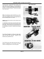
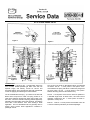
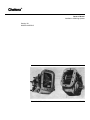
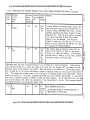
TM 5-4210-227-24&P-5
TECHNICAL MANUAL
ORGANIZATIONAL, DIRECT SUPPORT, AND
GENERAL SUPPORT MAINTENANCE MANUAL
(INCLUDING REPAIR PARTS AND
SPECIAL TOOLS LIST)
FOR
85' AERIAL LADDER
FIRE FIGHTING TRUCK
NSN 4210-00-965-1254
HEADQUARTERS, DEPARTMENT OF THE ARMY
5 NOVEMBER 1986
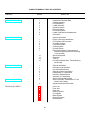
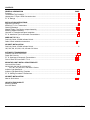
COMPLETE MANUAL TABLE OF CONTENTS
Publication
TM 5-4210-227-24&P-1
Section
Section Title
1
2
3
4
5
6
7
8
9
Introduction/Tabulated Data
Chassis Assembly
Pump Assembly
Ladder Assembly
Hydraulic System
Electrical System
Pneumatic System
Ladder Calibration and Adjustments
Illustrations
TM 5-4210-227-24&P-2
General Information
Engine (less major assemblies)
Fuel System and Governors
Air Intake Systems
Lubrication System
Cooling System
Exhaust System
Electrical Equipment, Instruments and
Protective Systems (Sections 8 through
11 not included)
Special Equipment
Operation
Tune-up
Preventive Maintenance, Troubleshooting
and Storage
1
2
3
4
5
6
7
12
13
14
15
TM 5-4210-227-24&P-3
TM 5-4210-227-24&P-4
TM 5-4210-227-24&P-5
1
2
3
4
5
6
7
8
1
2
General Information
Description and Operation
Preventive Maintenance
General Overhaul Information
Disassembly of Transmission
Rebuild of Subassemblies
Assembly of Transmission
Wear Limits and Spring Data
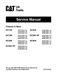
Allison Automatic Transmission HT 700
Series Parts Catalog
Supplemental Parts Information
1
2
3
4
5
6
7
8
Drive Line
Front Axle
Rear Axle
Steering System
Fuel System
Brake System
Electrical System
Miscellaneous
A
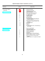
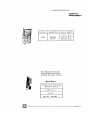
COMPLETE MANUAL TABLE OF CONTENTS (Continued)
Publication
TM 5-4210-227-24&P-5
(continued)
Section
Section Title
9
10
11
General Information
Installation Instructions
Troubleshooting and Service
General Information
Engine (less major assemblies)
Fuel System and Governors
Air Intake System
Lubricator System
Cooling System
Exhaust System
Electrical Equipment, Instruments and
Protective Systems
Power Take-off and Torque Converter
Transmissions (Sections 10 and 11 not
included)
Special Equipment
Operation
Tune-up
Preventive Maintenance, Troubleshooting
and Storage
TM 5-4210-227-24&P-7
1
2
3
4
5
6
7
8
9
12
13
14
15
TM 5-4210-227-24&P-8
TM 5-4210-227-10
Parts List and Foldouts
Tools and Equipment
Introduction/Tabulated Data
Operator's Instructions
Operator Maintenance
Illustrations
Operator's Manual, Series 92 Engines
Operator's Manual, Series V-71 Engines
Built-in Parts Book for Detroit Diesel
Engines
Operator's Manual, Fire Apparatus Chassis
1
2
3
4
5
6
7
8
B
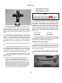
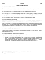
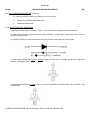
FOREWORD
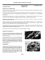
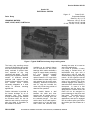
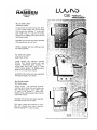
Descriptions, instructions and parts listing pertaining to the Model QWT 85 are discussed throughout this manual under
the general headings Chassis, Pump and Ladder. Foldout illustrations and schematics are located at the rear of this
volume. The foldout format is provided in order that illustrations and schematics may be referred to while the supporting
text is being examined and studied.
A detailed description is given in the Introduction of each volume to assist the user in finding the information required to
maintain the equipment.
•
Operator's Manual (TM 5-4210-227-10)
This manual is designed to provide the information necessary for a fire fighter or mechanic to properly operate
the truck, the pump and the ladder.
•
Maintenance Manual (TM 5-4210-227-24&P)
This manual is divided into 8 volumes and contains the information necessary for an experienced mechanic to
maintain and repair all facets of the apparatus. Each volume is individually indexed for ease of reference. This
manual contains all the information necessary to obtain assemblies and subassemblies or individual parts,
required to repair and maintain the fire truck.
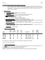
i/(ii blank)
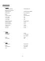
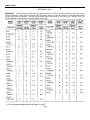
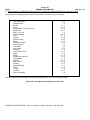
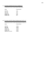
TABULATED DATA
a) Fire Truck
Federal Stock Number:
4210-00-965-1254
Manufacturer's Serial No.:
Registration Nos.:
CM3653 through CM3664
Manufacturer:
Pierre Thibault Inc.
Model:
QWT 85
Contract Number:
DAAJ10-84-A218
Truck Length:
459”
Truck Width:
108"
Truck Height:
138"
Capacity or Payload:
51,000 GVWR
Shipping Weight:
43,880
Ground Clearance:
10.25"
Weight Loaded:
45,940
Front Axle
19,740
Rear Axle
26,200
b) Chassis
Manufacturer:
Duplex
I.D. Number:
I.C. 1D91 D31
D6F 1008468
Model:
D350
Wheel Base
230"
c) Engine
Manufacturer:
Detroit Diesel
Model:
8V-71 Turbo
Serial Number:
8VA437868
Fuel:
Diesel
iii
d) Transmission
Manufacturer:
Model:
Serial No.:
Capacity:
Allison
HT-740
2510087501
7 1/2 Gals
e) Firefighting Water Pump
Manufacturer:
Model:
Capacity:
Hale
QSM FHD100
1000 GPM @ 150 psi
f)
f)
f)
Front Axle
Manufacturer:
Model:
Capacity:
Serial No.:
Rockwell International
FL 941 QX-70
20,000 lbs.
N766718
1. Front Shock Absorbers
Manufacturer:
Model:
Duplex
7605-1258
2. Front Springs
Manufacturer
Model:
Duplex
7804-6731
g) Rear Axle
Manufacturer:
Model:
Capacity:
Serial No.:
Rockwell International
U-170 PX-99
31,000 lbs.
NW8454892
g) 1. Rear Suspension
Manufacturer:
Model:
Hendrickson
Single Axle RS-SA-340
iv
h) Alternator
Manufacturer:
Model:
Amp.:
i)
j)
Delco Remy
145
Batteries
Manufacturer:
Model:
Voltage:
Harris
7605-0670
12
Battery Isolator
Manufacturer:
Model:
Rated Power:
Sure Power
1602
3709 BHP @ 2,100 rpm
k) Steering Gear
Manufacturer:
Model:
l)
Sheppard
7605-5478
Power Steering Pump
Manufacturer:
Model:
Vickers
7605-5256
m) Windshield Wipers
Manufacturer:
Model:
Type:
American Bosch
WWC-12L
Electric
n) Radiator
Manufacturer:
Model:
Blackstone
7605-3750
o) Air Cleaner
Manufacturer:
Model:
FAAR
62891-3
v
p) Driver's Seat
Manufacturer:
Model:
Type:
Bostrom
Four-way Adjustable
Standard
q) Wheels
Front:
Manufacturer:
Size:
Firestone
22.5 x 16.5
r)
Rear:
Manufacturer:
Size:
Firestone
20 x 8.5
Tires
Front:
Manufacturer:
Size:
Capacity:
Goodyear
16.5 R 22-5 - 18 P.R.
20,000 lbs.
Rear:
Manufacturer:
Size:
Capacity
Michelin
12:00 R 20X - 18 P.R.
31,000 lbs.
s) Muffler
Manufacturer:
Model:
t)
Nelson
86130-21
AC Inverter
Manufacturer:
Model:
Dynamote
A40-120
u) Siren/PA
Manufacturer:
Model:
Code 3
3100
vi
CAPABILITIES
Fire Truck
Turning Radius - Inside 31.5' - Outside 42.25'
Rated Power: 370 BHP @ 2,100 rpm
Engine Governor Setting: No Load - 2,100; Top
Speed 58 mph
Acceleration: 0 - 35 mph - 14 Seconds
Braking: 20 to 0 mph - 15 feet
Angle of Departure: Front - 15 degrees;
Rear - 15 degrees
Pump
Single Stage Centrifugal
Midship Mounted
Driven by the truck engine from the output shaft of
transmission
Min discharge - 1000 gpm @ 150 psi
Min discharge - 100 gpm @ 200 psi
Min discharge - 500 gpm @ 250 psi
From dry condition- - take suction and discharge water in 30
sec. with a lift of 10 deg. through 20' of 6”suction hose
12 VDC Priming Pump
Water Tank - 2b0 gals.
Ladder
Basic Weight - 11,560 lbs.
Outrigger Operation Speed
Lower: Front - 9 sec.
Rear - 18 sec.
Raise: Front - 9 sec.
Rear - 18 sec.
Complete extension, elevation and 90 degrees rotation
in 60 sec.
Hydraulic Tank: 45 gals. (Imp.)
-vii-
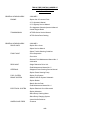
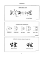
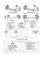
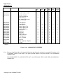
TRUCK FIRE FIGHTING LADDER 85'
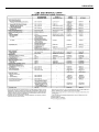
INDEX TO COMMERCIAL
PUBLICATIONS
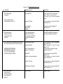
GENERAL HEADING INDEX
ENGINE
- VOLUME 2
- Duplex List of Common Parts
- V-71 Operator's Manual
- V-71 Highway Service Manual
- Fire Apparatus Chassis Operator's Manual
- Jacobs Engine Brake
TRANSMISSION
- HT700D Series Service Manual
- HT700 Series Parts Catalog
GENERAL HEADING INDEX
DRIVE LINES
- VOLUME 3
- Duplex Drive Lines
- Spicer Service Manual
- Spicer Trouble Shooting Guideline
FRONT AXLE
- Front Suspension
- Front Axle
- Rockwell Field Maintenance Manual No. 2
- Lubrication
REAR AXLE
- Single Reduction Drive Unit
- Field Maintenance Manual No. 5
STEERING
- Sheppard Power Steering Service Manual
- Duplex Power Steering Pump
FUEL SYSTEM
- Duplex Fuel System
BRAKE SYSTEM
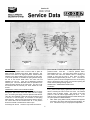
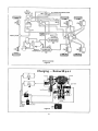
- Model D-350 Air System Schematic
- Duplex Brakes
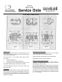
- Bendix Service Data
- Field Maintenance Manual No. 4
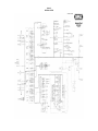
ELECTRICAL SYSTEM
- Duplex Electrical Circuit Schematic
- Duplex Alternator
- Delco Remy Cranking Motor
- Delco Remy Charging System
- Leece Neville Switches
WHEELS AND TIRES
- Firestone
-viii-
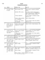
MISCELLANEOUS
- Duplex Bumper
- Duplex Tow Hooks
- Air Horn
- Electric Wiper
- Mirror Assembly
- Cab Exterior
- Exterior Cab Lights
- Cab Interior
- Heater Assembly
TAB INDEX VOLUME 3
CHASSIS
PUMP
HYDRAULICS
1.
- PTO
2.
- Body Hardware
3.
- Electrical
4.
- Tools and Equipment
5.
- Lights
6.
- Siren/PA, Intercom
10.
- Butterfly Valves
11.
- Drain Valves
13.
- Feecon Foam Systems
14.
- Hale Pump and Valves
15.
- Gauges
16.
- Controls
17.
- Water Tower Tip
20.
- Bourdon Tube
21.
- Relief/Unloader Valve
22.
- Directional Valves
23.
- Selector Valves
24.
- Pumps and Motors
25.
- Solenoid Valves
26.
- Regulators
27.
- Cylinders
28.
- Electrical Controls
-ix-
MAINTENANCE MANUAL
SECTION I
1.
INTRODUCTION/TABULATED DATA
1.1
INTRODUCTION
1.1.1.
TM 5-4210-227-24&P, Organizational, Direct Support, and General Support Maintenance Manual
for the 85' Aerial Ladder Fire Fighting Truck is divided into eight volumes. These eight volumes are
further subdivided into specific sections consisting of both Government and commercial literature. TM 54210-227-10, Operator's Manual for the 85' Aerial Ladder Fire Fighting Truck is one separate manual
consisting of four separate sections.
1.1.2.
This volume consists of 11 sections and is arranged as follows:
1.
Drive Line
2.
Front Axle
3.
Rear Axle
4.
Steering System
5.
Fuel System
6.
Brake System
7.
Electrical System
8.
Miscellaneous
9.
General Information
10.
Installation Instructions
11.
Troubleshooting and Service
x
Section I
Section I
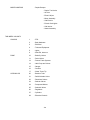
DRIVE LINES
FOREWORD
This manual is presented as a guide in solving problems associated with drive shafts. No attempt has been
made to discuss technical consideration of design or theory of vibrating systems.
In discussing installation of drive shafts, no hard and fast rule or fine dividing line has been drawn between
satisfactory and unsatisfactory operation.
The limits set forth in this manual correspond with our own standards. Our long experience in the manufacture
and installation of drive shafts has proven these standards to be accurate.
INDEX
Subject ....................................................................................
Page
Function ..................................................................................
3
Construction ............................................................................
4
Nomenclature ..........................................................................
5, 6
Universal Joint Seals ...............................................................
7
Lube Specs..............................................................................
8, 9
Recommended Lubricants .......................................................
9
Service Instructions .................................................................
10-12
Removal..................................................................................
10
Disassembly ............................................................................
11
Cleaning & Inspection..............................................................
12
Failure Analysis .......................................................................
12
Rebuilding ...............................................................................
13
Installation ...............................................................................
14-16
© 1967 DANA CORPORATION
LITHO IN U.S.A.
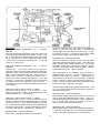
2
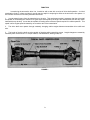
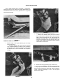
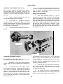
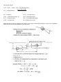
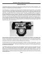
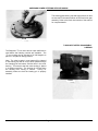
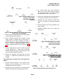
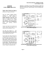
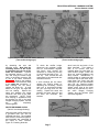
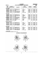
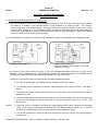
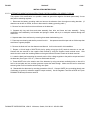
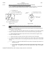
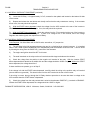
FUNCTION
In examining the automotive drive line, it would be well to start with a review of drive shaft operation. A critical
examination of why it is there and what it must do may be helpful in analyzing its effect on the entire drive line system. A
drive shaft's functions can be briefly described as follows:
1. It must transmit torque from the transmission to the axle. This requirement makes it necessary that the drive shaft
be capable of transmitting the maximum low gear torque developed by the engine and transmission ratio and any shock
loads which may develop. It must also be capable of rotating at the maximum speed required for vehicle operation. This
speed is often engine speed increased by an overdrive ratio in the transmission.
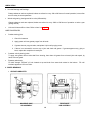
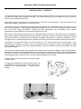
2. The drive shaft must operate through constantly changing relative angles between transmission drive shaft and
axle.
3. The length of the drive shaft must be capable of changing while transmitting torque. Length changes are caused by
necessary axle movement Sue +o torque reaction, road deflections, braking loads, etc.
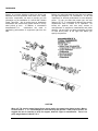
FIGURE 1
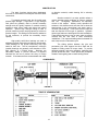
3
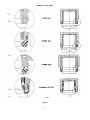
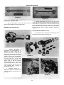
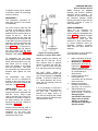
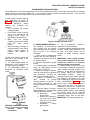
CONSTRUCTION
or abrasive material, needle bearing life is seriously
affected.
The basic functions having been designated,
let's look at conventional universal joint and drive shaft
construction.
Abrasive material is a major problem where a
vehicle operates under conditions of extreme moisture
and dirt.
Off-highway installations are especially
critical in this respect. Military trucks represent the
extreme in this direction and were the first to show the
shortcomings in the conventional cork seals used in
universal joint bearings. It was found that an improved
seal was required for this type of operation. Synthetic
rubber-type seals were developed for these installations.
These seals have been in use for many years on military
vehicles and are now used in most commercial
installations. The improved sealing shows increased life
and a less critical re-lubrication cycle.
To transmit required loads, the drive shaft must
possess high strength. Forged steel, or high strength
cast yokes are generally used to provide necessary
strength and the rigidity required to maintain bearing
alignment under torque loads and during high speed
operation. Special high strength tubing is used to
provide maximum torque carrying capacity at minimum
practical weight. This tubing must be securely welded to
its end members, to provide the necessary torque
capacity.
High quality anti-friction bearings are used to
withstand required loads while oscillating at high speeds.
These bearings on the journal cross carry very high
loads for their size. The full complement, roller-type
(needle) bearings are generally used because of their
high capacity in a limited space.
Bearings are
individually sealed to provide retention of required
lubricants as well as to prevent the entry of foreign
material. If lubricants become contaminated with water
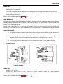
The sliding splines between slip joint and
permanent joint must support the drive shaft and be
capable of sliding under full torque loads. To provide
adequate strength and wear resistance, hardened and
ground splines are used. These splines are phosphate
coated to resist galling and to reduce sliding friction.
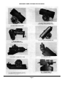
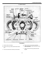
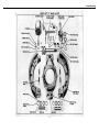
COMPONENTS
FIGURE 2
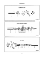
4
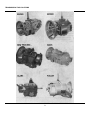
COMPONENTS
FIGURE 3
FIGURE 4
FIGURE 5
5
COMPONENTS
FIGURE 6
FIGURE 7
FIGURE 8
6
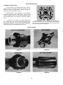
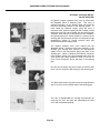
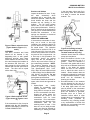
UNIVERSAL JOINT SEALS
Figure 9
7
LUBE SPECS
Don't Neglect Spicer
Drive Shaft Lubrication!
Lack of adequate or proper lubrication is among the most
common causes of U-Joint and drive shaft failure
Proper servicing of the drive shaft is an essential part of
vehicle maintenance and should not be overlooked in routine
shop procedure.
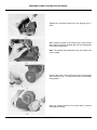
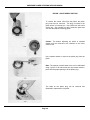
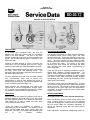
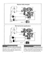
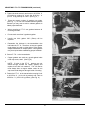
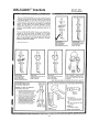
Universal Joints
In the Vehicle or Application
To insure proper lubrication of all four bearing assemblies
on Spicer universal joints, it is essential that mechanics add
lubricant until it appears at all journal cross bearing seals
(Illustration A). This assures removal of dirt particles and other
contaminants that may find their way into the bearings and
indicates to the mechanic that the bearings are fully lubricated.
Do not assume that bearing cavities have been filled with
new lubricant unless flow is noticed around all four bearing
seals!
Spicer journal cross seals are designed to relieve.
However, if all the seals do not "pop" when being lubed, move
the driveshaft laterally in all four directions and pull or push on
the drive shaft in the direction opposite to the journal cross seal
not relieving while lube gun pressure is being applied to the
alemite fitting. An increase in line pressure may also be
necessary.
Drive Shaft Assembly
Spicer factory assembled drive shafts are lubricated at the
plant prior to shipment. However, shipping, handling and
installation of the drive shaft assembly into the vehicle usually
results in some loss of lube. Therefore, it is recommended that
all universal joints be relubricated after installation of the drive
shaft prior to putting vehicle in service
Journal and Bearing Kits
Spicer replacement universal joint kits contain only enough
grease to provide needle bearing protection during storage.
It is therefore necessary to completely lubricate each
replacement kit prior to assembly into the drive shaft yokes. Each
journal cross lube reservoir should be fully packed with a
recommended grease and each bearing assembly should also be
wiped with the same grease; filling all the cavities between the
rollers and applying a liberal grease coating on the bottom of each
race. After the kits are installed into the driveshaft yokes and prior
to placing into service, they should be relubed, through the zerks,
using the same grease.
8
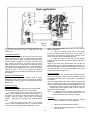
LUBE SPECS
Lubricants
For driveshaft applications involving shaft speeds over 500
RPM, a high quality extreme pressure (EP) grease
recommended by lubricant manufacturers for universal joints
should be used. Lithium soap base greases meeting *NLGI
Grade 1 and Grade 2 specifications are preferred. The use of
greases that tend to separate and cake should be avoided.
For driveshaft applications involving shaft speeds below
500 RPM, a mineral oil in the SAE 140 to SAE 250 viscosity
range should be used.
*National Lubricating Grease Institute
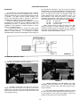
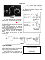
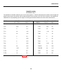
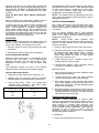
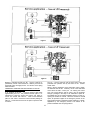
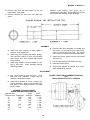
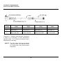
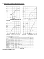
Relube Cycles
Relubrication cycles for drive shaft universal joints and slip
splines will vary with service requirements and operating
conditions. The following re-lubrication schedule has been
used successfully.
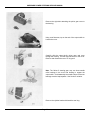
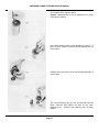
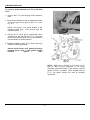
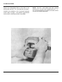
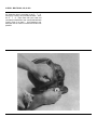
Relube spline at the intervals prescribed above. Apply
grease gun pressure to lubrication zerk until lubricant appears
at pressure relief hole in welch plug at sleeve yoke end of
spline. (Illustration B). At this point, cover pressure relief hole
with finger and continue to apply pressure until grease
appears at sleeve yoke seal. (Illustration C). This will insure
complete lubrication of spline.
RE-LUBE CYCLE
OPERATING CONDITION
Normal
*Severe
Miles
Hours
6000-8000
2000-3000
150-200
50-75
* For applications where conditions such as high speeds, high
ambient temperatures or high angles are present.
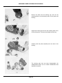
Center Bearings
Initial lubrication is done by the bearing manufacturers. No
attempt is made to add or change grease within the
commercial bearing itself.
However, when servicing a
driveshaft in the field with a new center bearing, it is necessary
to fill the entire cavity around the bearing with waterproof
grease to shield the bearing from water and contaminants. The
quantity should be sufficient to fill the cavity to the extreme edge
of the slinger surrounding the bearing.
Sliding Spline Sections
Lubricants
Steel Splines: Driveshaft steel splines should be lubricated
with a good extreme pressure grease as recommended by
lubricant manufacturers. Extreme pressure grease satisfying
NLGI Grade 1 has been adopted as the standard by our
factories.
Glidecote TM Splines: Any high grade multi-purpose grease
can be used.
Greases-recommended by lubricant
manufacturers for universal joints have been found satisfactory
for Glidecote splines.
Lubricants used must be waterproof. Consult your grease
supplier for recommendation.
9
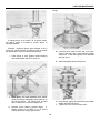
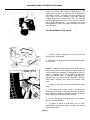
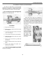
SERVICE INSTRUCTIONS
Spicer needle bearing joints are simple in construction,
easily removed from the vehicle and readily disassembled and
reassembled without the use of any special tools or any special
mechanical knowledge.
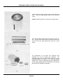
FIGURE 13
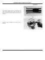
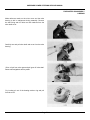
2. Double End, Yoke Type (U-Bolt Construction)
Remove the U-Bolts, Nuts, and Lock Washers
from the End Yokes. Slide the Sleeve Yoke toward the
shaft to free the Bearings from their seats between the
shoulders in the End Yokes. Care should be taken not
to drop the two Bearings from the trunnion ends of the
Journal Cross at both ends of the drive shaft. The End
Yokes remain on the vehicle.
FIGURE 11
REMOVAL FROM THE VEHICLE
1.
Double Flange, Yoke Types (Bearing Cap and Snap
Ring Construction)
All Double Flange Yoke Type Joints are removed
as a complete assembly by removal of the Companion
Flange Bolts, Nuts, and Lock Washers, which allows
the assembly to slip out from between the Companion
Flanges.
FIGURE 14
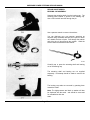
3. Double End Yoke Type (Bearing Cap Construction)
Remove the cap screws, lock plates and bearing and
retaining cap sub-assemblies, from the transmission and
axle end yokes. Remove the drive shaft with the remaining
journal crosses and bearings as a unit. The end yokes
remain on the vehicle.
FIGURE 12
10
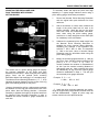
SERVICE INSTRUCTIONS
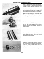
FIGURE 15
FIGURE 16
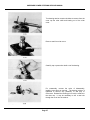
REMOVAL OF THE SLIP JOINT
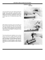
2. ARROW MARKS-Make sure arrow marks are stamped
on the shaft and sleeve yoke before removing the slip joint. If
1. Slip Joint (All Types). Unscrew the dust cap from the
arrow marks are not readily seen, mark both members so that
sleeve yoke and slide the joint off the drive shaft.
when reassembled they will be in exactly the same relative
position, since the sleeve yoke lugs must be in the same plane
as the stub ball yokes to prevent excessive vibration in
BEARING CAP CONSTRUCTION
operation.
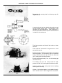
DISASSEMBLING UNIVERSAL JOINT
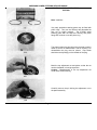
1. LOCK STRAP (98) - Bend down the locking lugs with a
screwdriver and remove the cap screws (73).
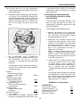
2.
NEEDLE BEARINGS &
RETAINING CAP SUBASSEMBLY (6)
Remove by using a large pair of
channel lock pliers on retaining cap
edges, turn retaining cap and bearing
sub-assembly at the same time lifting
upward to remove the sub-assembly
from the journal trunnion diameter and
out of the yoke hole. Turn the joint
over and tap the exposed end of the
journal cross (5) until the opposite
needle bearing is free. Use a soft
round drift with flat face about 1/32"
smaller in diameter than the hole in the
yoke, otherwise there is danger of
damaging the bearing.
FIGURE 17
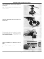
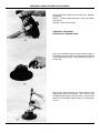
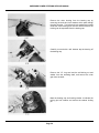
3.
JOURNAL CROSS (5)
Remove by sliding it to one side of the
yoke and tilting it over the top of the
yoke lug.
FIGURE 18
11
FIGURE 19
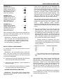
SERVICE INSTRUCTIONS
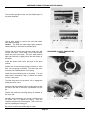
CLEANING AND INSPECTION
1. Clean All Parts Use a suitable cleaning fluid. Allow the
parts to remain in the cleaner for some time to loosen up any
particles of grease or foreign matter. Remove any burrs or
rough spots from any machined surfaces.
2. Needle Bearings - Do not disassemble. Clean with short
stiff brush and blow out with compressed air. Work a small
quantity of lubricant (140 S.A.E. Oil) into each bearing cap and
turn the needle bearing on the trunnion to check wear. Replace
if worn.
3. Journal Cross - Because worn needle bearings used
with a new journal cross or new needle bearings used with a
worn journal cross will wear more rapidly making another
replacement necessary in a short time, always replace the
journal cross and four needle bearings caps as a unit,
Journal and Bearing Kit -To facilitate the replacement of
journals and bearings, a Journal and Bearing Kit is available.
The use of the Kit insures having the correct individual parts
when required and saves valuable time.
TYPICAL FAILURES
FIGURE 21
FIGURE 22
FIGURE 23
FIGURE 24
12
REBUILDING DRIVESHAFTS
be sure parts are centralized. This can be done by mounting
shaft assembly on center and straightening at fittings until ends
of tube run concentric within about .005 TIR. The welding of the
tube in the fittings must provide for adequate strength and
prevent distortion which could cause excessive runout. It is
often desirable to tack weld and recheck for runout before
proceeding with final weld. After welding, the entire drive shaft
should be straightened to the following limits: (See Fig. 25)
.005 TIR
On shaft neck
.015 TIR
On ends of tubing 3" from welds
.010 TIR
In center of tube
These runouts should be taken with entire drive shaft
assembly mounted on master attaching flanges or yokes,
selected for dynamic balance to eliminate as much unbalance
as possible. During balancing, the drive shaft again should be
mounted on these selected flanges or yokes.
BALANCING
The rebuilding of a drive shaft assembly usually consists of
replacing worn journal cross and bearings with a new kit.
These kits replace the part of a drive shaft most subject to wear
in operation. The slight off-center condition present in the
journal cross assemblies makes it desirable to balance the
assembly after installing new journal and bearing kits.
Generally, unbalance resulting after installation of a journal
and bearing kit is equivalent to the unbalance existing after
straightening the shaft. If balancing cannot be done, it is
advisable to check assembly for smooth operation in vehicle
before it is put into operation.
It is sometimes necessary to revise drive shaft lengths
when rebuilding a vehicle. This job requires proper facilities to
produce a quality assembly. It is necessary to properly
assemble fittings into the tube and straighten, before welding, to
FIGURE 25
ASSEMBLING UNIVERSAL JOINT
1. Seal - If unnecessary to install a new kit make sure that
four new seals are installed in the journal retainers.
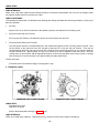
FIGURE 27
3.
NEEDLE BEARING AND RETAINING CAP SUBASSEMBLY Insert from outside of yoke. Press into place with
an arbor press or tap with a soft round drift taking care not to
mar any surfaces.
FIGURE 26
2. JOURNAL CROSS With the relief valve facing the
flange yoke, insert one trunnion of the journal cross into the
bearing hole in the yoke lug from the inside between the lugs
and tilt until the trunnion of the journal cross will clear the hole
in the opposite yoke lug.
4. LOCK STRAP AND CAP SCREWS Assemble and bend
the lugs of the lock strap up against the flat of the cap screw. If
the joint appears to bind, tap the lugs lightly to relieve any
pressure of the bearing on the end of the journal.
13
INSTALLATION
5/16"-24 Thread
3/8"-24 Thread
7/16"-20 Thread
1/2"-20 Thread
22 to 24 lbs. ft.
40 to 44 lbs. ft.
63 to 70 lbs. ft.
98 to 108 lbs. ft.
NOTE
In cap and bolt construction joints (Fig. 7), be sure to
torque the cap screws to 100 lbs. ft. These joints are
usually the Spicer 1650 Series interaxle assemblies.
2. U-Bolt Style Yokes: On smaller size universal joints, a
"U" bolt style end yoke is used. This construction permits
easier assembly where the smaller size bearings allow its use.
The bearing race is seated in a half round hole and under
locating ears. Be sure that mounting faces are cleaned of rust,
paint and other foreign material. The "U" bolts are assembled
over the bearing races to retain them in the end yokes. Spring
lock washers and nuts should be used with these "U" bolts at
assembly. The following torque loads are suggested for use
with these parts:
FIGURE 28
1650 SERIES JOURNAL CAPS WITH LOCK FLATS When installing new journal kit caps into yoke ear holes, the
lock flat on two of the journal caps must be kept in alignment
with the locking flats near the front of the yoke ears. Proper
location of locking flats will assure that the journal cap will not
rotate.
5/16"-24 Thread
3/8"-24 Thread
7/16"-20 Thread
The installation of a drive shaft into the vehicle does not
present any unusual mechanical difficulties. Before actual
installation, the drive shaft should be checked for the following
items: 1. No damage or dents on drive shaft tubing which
could cause unbalance. If the dents are severe enough they
can weaken the tube and a failure might occur under torque
load.
14 to 17 lbs. ft.
20 to 24 lbs. ft.
32 to 37 lbs. ft.
These torque loads are somewhat lighter than normally
used with these thread sizes, however, the lower torques
are required to prevent bearing race distortion.
ASSEMBLING SLIP JOINT ON SHAFT
2. Splines should slide freely with slight drag from spline
seal.
Lubricate the splines thoroughly (refer to page 9) and
assemble on the Shaft. BE SURE that the arrows or marks on
the Shaft and Slip Joint are in line, since the Sleeve Yoke Lugs
must be in the same plane as the Stub Ball Yoke lugs to
prevent excessive vibration.
3. Bearings should flex and be free from excessive bind. A
slight drag is the most desirable condition on a new universal
joint. This drag is from the bearing seals. When rotating, yoke
lug deflections cause some additional clearance. Excessive
looseness is not desirable due to the resulting unbalance.
The cork washer should be replaced if necessary before
assembling with the dust cap and steel washer on the Sleeve
Yoke.
4. Mounting flanges and pilots should be free from burrs,
paint and foreign substances which would not allow proper
seating at assembly.
The drive shaft is mounted using flange bolts, bearing cap
screws, or "U" bolts depending upon the size and
construction. These bolts must carry high torque loads and
should be of quality material and properly torqued. The
following reviews requirements on these bolts: 1. Flange
Bolts: Flange Bolts should be alloy steel equivalent to SAE
Grade 8, high-strength bolts. These bolts used with spring
lock washers and nuts provide the capacity required. The
nuts should be torqued to the following specifications:
14
INSTALLATION
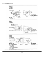
4.
If a vehicle has drive shafts that do not have
intersecting angles but parallel angles throughout the
drive line system, the yokes or flanges must be held
parallel to within 1°of each other.
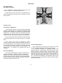
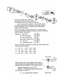
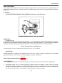
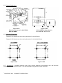
UNIVERSAL JOINT PHASING (See Fig. 29)
When U-joints or yokes are assembled to their shafts in
the same plane, they are in phase. When they are
assembled to the shaft in different planes, they are out
of phase. To obtain vibration free operation, check the
following.
INSTALLING DRIVESHAFT
1.
Drive Shaft Assembly Place in a pair of
centers and check the Shaft for runout if not previously
done during assembly. The runout on the Tube should
not be more than .015" indicator reading, and on the neck
of the Slip Stub Shaft the runout should not be more than
.005" indicator reading. Mark the high and low points on
the shaft with chalk and straighten if necessary. Install
with the Slip Joint nearest the source of power. Tighten
the Flange Bolts evenly after the Nuts and NEW Lock
Washers are in place.
1.
Yokes or flanges between the main and
auxiliary transmission must be "In Phase".
2.
In the case of a two-piece drive shaft
assembly, between the transmission (Main or Auxiliary)
and the forward rear axle, the joints on this shaft should
be assembled "In Phase", unless otherwise specified by
the manufacturer of the vehicle.
3.
Phase".
The inter-axle drive shaft yokes must be "In
FIGURE 30
FIGURE 31
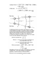
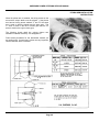
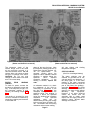
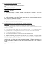
CHECKING DRIVESHAFT ANGLES
be understood to be the same as 0° on the horizontal
plane. Thus, if a vertical reading is 85°, the angle being
measured is 5°.
3.
All angles should be read within ¼ ° (15 min.)
and they should be measured with the protractor held
plumb on a clean, flat surface.
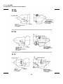
The procedure to check drive shaft angles for proper
universal joint operating angles follows:
1.
Remember to check drive shaft angles both
with the tractor fifth wheel unloaded, and loaded with a
trailer.
4.
Inflate all tires to the pressure at which they
are normally operated. Park the tractor on a surface
which is as nearly level as possible both from front-torear and from side-to-side.
2.
To determine drive shaft angles, a spirit
level protractor is required. When angles are read from
the 0° mark (for example, measuring inter axle shaft
angle 5°), record and use the angle shown on the
protractor. When angles are read from either of the 90°
marks (vertically) for example, measuring yoke angles,
do not record the angle shown on the protractor since
the 90°marks must
5.
The tractor must be in its normal operating
position. Do not attempt to level the truck by jacking up
the front or rear axles to obtain a level condition
15
INSTALLATION
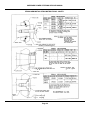
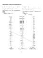
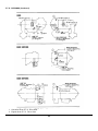
11. With all the above angles recorded, these
values are checked to obtain the journal cross operating
angles of each drive shaft set to determine if they are
operating to within a 3° maximum of each other. If the
operating angles or journals exceed 3°, it will cause early
wear, and possible seizure of the journal to the needle
bearing in the journal cap.
FIGURE 32
6.
Check and record the angle on the engine and
main transmission. This reading can be taken at the rear
of the main transmission on the output yoke, or flange.
Record this reading on a sketch similar to Fig. 32.
(Example on Figure 32-1°down).
7.
Move protractor to the 0° reading and check
drive shaft angle between transmission and forward axle
(Example 4°30' down).
8.
Check front axle input yoke angle with
protractor (Example angle up 2°30'), also check front axle
output yoke (Example angle down 2°20').
9.
Measure the angle of the tandem drive shaft
between the front axle and first rear axle (Example 5°
down).
10. Measure the rear axle input yoke angle
(Example 12°up).
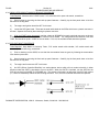
FIGURE 33
TORQUE ARM SHIMMING
The adding or removing of shims' from the rear axle
torque arm will change the angle of the interaxle drive
shaft. Therefore, it is necessary to take the drive shaft
angle and the rear axle yoke angle after each adjustment is
made, to determine the journal operating angle.
SHORT COUPLED JOINTS
Short coupled joints must be installed so that the
front and rear joints will have equal angles which should
not exceed 3°.
BULLETIN 3304-1
16
For further information write to:
Universal Joint Division
Dana Corporation
P.O. Box 374
Toledo, Ohio 43601
Rev. 4-73
Section I
DRIVE LINES
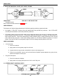
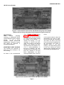
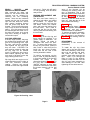
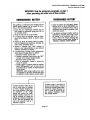
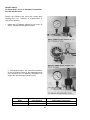
Universal joint failures, as a rule, are of a progressive nature, which, when they occur, generally accelerate rapidly
resulting in a mass of melted trunnions and bearings.
Some recognizable signs of universal joint deterioration are:
1) Vibrations Driver should report to maintenance.
2) U-Joint Looseness-End play across bearings.
3) U-Joint discoloration due to excessive heat build-up.
4) Inability to purge all four trunnion seals when re-lubing U-joint.
Item 2) thru 4) should be checked at re-lube cycle and if detected reported to the maintenance supervisor for
investigation.
Experience with universal joint failures has shown that a significant majority are related to lubricating film
breakdown. This may be caused by a lack of lubricant, inadequate lube quality for application, inadequate initial
lubrication or failure to lubricate properly and often enough.
Failures which are not a result of lubrication film breakdown are associated with the installation, angles and speeds
and manufacturing discrepancies.
Drive shaft failures through torque, fatigue and bending are associated with overload, excessively high U-joint
angles and drive shaft lengths excessive for operating speeds.
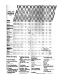
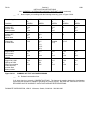
The trouble shooting chart in this bulletin is intended to provide service people with an aid to enable them to
associate complaints with some of the probable causes and probable corrections. Which through normal vehicle
maintenance and recognition of discrepancies may enable them to make necessary corrections to ward off a serious
breakdown.
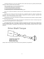
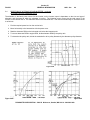
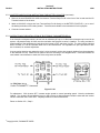
Drive Shaft Torque
Usually a result of torque overload - How much torque can be generated in your application?
2
Here is how to figure!
L.G.T. = N.E.T. x Trans. L.G.R. x .85 (efficiency factor)
D.L.T. (to Slip Wheels) =
WR x C.O.F. x R.R.
12 x A .R.
A.R. = Axle ratio
L.G.T. = Low gear torque
C.O.F. = Coefficient of friction (.7)
N.E.T.= Net engine torque
D.L.T. = Drive line torque
R.R. = Tire loaded rolling radius
L.G.R. = Low gear ratio
WR = Weight on drive axle
Relate the lesser of above to Spicer U-joint ratings. If your torque exceeds Spicer rating for U-joint size in application
switch to a size with a rating compatible to your calculation.
3
4
5
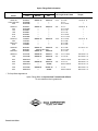
7
6
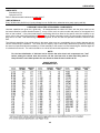
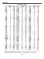
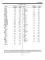
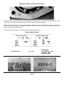
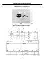
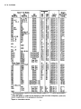
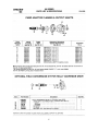
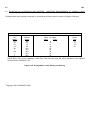
Spicer Flange Bolt Information
Part Numbers
Series
Bolt
Washer
Nut
1000/1100
1350/1410/1550
1550*
5-73-414
5-73-2216
5-73-1125
500357-10
"
"
231421-2
"
1280/1310
1610
1710
1760
1610*
1710*
6-73-316
6-73-1219
6-73-220
6-73-220
6-73-325
6-73-1227
500357-11
"
"
"
"
"
231421-3
1350/1410
1810
1350/1410*
1810*
7-73-219
7-73-122
7-73-126
7-73-228
500357-12
"
"
"
231421-4
"
"
1480/1550
1650
1480/1550*
8-73-122
8-73-123
8-73-228
1880/1910
Diameter, Thread,
and Length Under Head
Recommended
Torque
5/16" -
24 x 7/8"
24 x 1"
24 x 1-9/16"
22-26 Lb. Ft.
"
"
3/8" -
24 x 1"
24 x 1-3/16"
24 x 1-1/4"
24 x 1-1/4"
24 x 1-9/16"
24 x 1-11/16"
40-48 Lb. Ft.
"
7/16" -
20 x 1-3/16"
20 x 1-3/8"
20 x 1-5/8"
20 x 1-3/4"
63-75 Lb. Ft.
"
"
"
500357-13
231421-5
(Bearing Race Cap)
500357-13
231421-5
1/2" -
20 x 1-3/8"
20 x 1-7/16"
20 x 1-3/4"
97-116 Lb. Ft.
"
"
10-73-131
500358-15
231421-7
5/8" -
18 x 1-15/16"
194-232 Lb. Ft.
1950
12-73-140
500358-17
231421-8
3/4" -
16 x 2-1/2"
341-409 Lb. Ft.
2010
9.55-73-11
---
231483
18mm x 75mm
277-319 Lb. Ft.
2050
14-73-264
500358-19
231421-9
9 x 3-1/2"
543-652 Lb. Ft.
2110
9.60-73-11
---
231482
20mm x 80mm
397-457 Lb. Ft.
2150
16-73-164
500358-21
231421-10
12 x 4"
810-976 Lb. Ft.
2210
9.65-73-11
---
231481
22mm x 90mm
534-575 Lb. Ft.
"
"
"
"
"
"
"
7/8" -
1"
-
*- Tru Stop Brake Applications
Spicer Flange Bolts are Special Heat Treated Grade 8 Bolts.
Do not substitute inferior grade bolts.
Form 3119-1 5/84
"
"
"
"
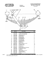
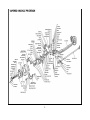
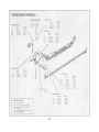
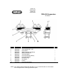
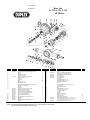
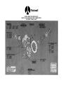
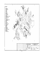
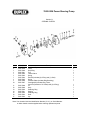
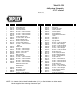
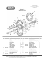
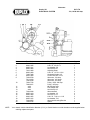
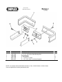
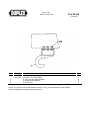
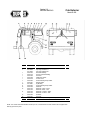
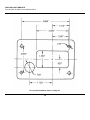
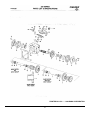
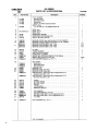
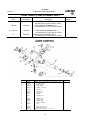
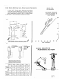
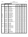
Section II
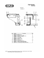
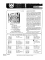
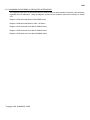
FRONT AXLE
Item
1
2
3
4
5
6
7
8
9
10
11
12
13
14
15
16
17
18
19
20
21
22
23
24
25
26
NOTE:
Part No.
7605-1350
7810-6394
7808-1978
7601-7831
7602-7938
8850-1008
7604-1781
7810-3750
7601-7822
7604-6339
7605-1258
7804-6731
7801-7734
7810-1645
7605-0175
8820-1555
8855-1012
8850-1307
7801-7662
8850-1312
7810-6397
7808-1979
7604-1780
8867-1001
7604-1706
8851-1106
8863-1309
7800-6279
Description
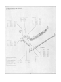
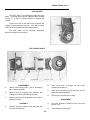
Spring Hanger
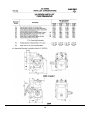
RH Frame Shock Bracket (Shown)
LH Frame Shock Bracket
H.H.C.S. 1/2-13 x 1-1/2
Hard Washer 1/2
Hex Nut 1/2-13
Mounting Stud
Rubber Bushing
Hard Washer 5/8
Lock Nut 5/8-18
Shock Absorber
Spring Assembly
Spring Clip Seat
Spring Clip
Spring Hanger
H.H.C.S. 7/16-20 x 2-1/2
Lockwasher 7/16
Hex Nut 7/16-20
Spring Seat
Hex Nut 3/4-16
RH Axle Shock Mount (Shown)
LH Axle Shock Mount
Spring Pin
Lube Fitting
H.H.C.S. 3/8-24 x 5-1/4
Castle Nut 3/8-24
Cotter Pin 3/32 x 3/4
Bushing
Qty.
2
1
1
4
4
4
4
8
4
8
2
2
2
4
2
12
12
12
2
16
1
1
6
6
2
2
2
2
Your chassis Vehicle Identification Number (V.I.N.), or Serial Number on older chassis must be supplied
when ordering replacement parts
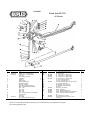
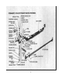
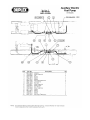
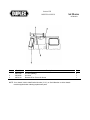
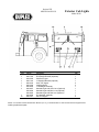
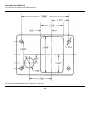
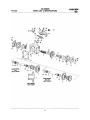
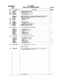
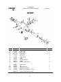
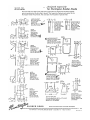
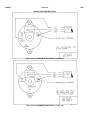
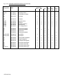
SectionII
Front Axle FL-931
All Models
Item
1
2
Part No.
7605-2007
7605-1996
3
4
5
6
7
8
9
10
11
12
13
14
15
16
17
18
7605-1997
Description
Key
Steering Arm – LH (Ross Gear)
Steering Arm – LH (Spicer Gear)
Cotter Pin
Nut – Steering Arm Ball
Lockwasher
Capscrew
Grease Fitting
Steering Knuckle Cap
Knuckle Cap Gasket
Brushing – Knuckle
Nut – Steering Knuckle Draw Key
Seal – Knuckle Pin Upper Assembly
Shim – .005
Shim –.010
Shim –.030
Shim -.015
Seal – Steering Knuckle Lower Assembly
Thrust Bearing
Cotter Pin
Axle Center
Key – Steering Knuckle DR. Upper
Qty.
3
1
1
3
1
12
12
4
4
4
4
4
2
2
2
2
2
2
2
4
1
2
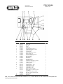
Item
19
20
Part No.
7605-2009
7605-2010
7605-1998
7605-1999
21
22
23
24
25
26
27
28
29
7605-2000
30
7605-2005
7605-2006
7605-2001
7605-2002
7605-2003
7605-2011
7605-2004
Description
Key - Steering Knuckle DR. Lower
Nut - Tie Rod End
Arm - Cross Tube L.H. (Ross Gear)
Arm - Cross Tube L.H. (Ross Gear)
Arm - Cross Tube L.H. (Spicer Gear)
Arm - Cross Tube L.H. (Spicer Gear)
Tie - Rod – End Assembly R.H.
Tie - Rod – End Assembly L.H.
Cross Tube Assembly (Items 3,19,21,23,24,25)
Bolt – Steering Cross Tube
Clamp Steering Cross Tube End
Nut – Steering Cross Tube Clamp
Knuckle Pin
Stop Screw – Axle Center
Locknut – Stopscrew
Knuckle – Steering Assembly L.H.
Knuckle – Steering Assembly R.H. (Ross Gear)
Knuckle – Steering Assembly R.H. (Spicer
Gear)
Ball – Steering Arm 1-3/4 Dia
Knuckle Pin Kit (Items 5,6,8,9,10,11,12,13
14,15,18,26)
NOTE: Your chassis Vehicle Identification Number (V.I.N.) or Serial Number on order chassis must be supplied
when ordering replacement parts.
Qty.
2
2
1
1
1
1
1
1
1
2
2
2
2
2
2
1
1
1
1
2
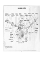
Section II
FRONT AXLE
1
TABLE OF CONTENTS
SUBJECT
PAGE
DISASSEMBLY - FRONT AXLE ..................................................................................................................................
Remove the Steering Knuckle ............................................................................................................................
PREPARATION FOR ASSEMBLY ..............................................................................................................................
Reconditioning of Components ...........................................................................................................................
Cleaning .............................................................................................................................................................
Rough Parts........................................................................................................................................................
Drying.................................................................................................................................................................
Corrosion Prevention ..........................................................................................................................................
Aluminum Beam Galvanic Corrosion Protection .................................................................................................
Inspection ...........................................................................................................................................................
Tie Rod and Tie Rod End Inspection...................................................................................................................
Rebuilding Tie Rod End Assemblies ...................................................................................................................
Wheel Bearing Inspection...................................................................................................................................
Repair and Check Procedures for Aluminum Beam Axles...................................................................................
ASSEMBLE FRONT AXLE..........................................................................................................................................
Replacement of Bronze or Steel Backed Bronze Steering Knuckle Bushings ......................................................
Bushing Removal and Installation Tool ...............................................................................................................
Bushing Installation.............................................................................................................................................
Bushing Sizing Methods .....................................................................................................................................
Reaming Procedure............................................................................................................................................
Reaming Specifications ......................................................................................................................................
Grease Seal Installation......................................................................................................................................
Thrust Bearing Seal Assembly............................................................................................................................
Knuckle to Axle Center Assembly .......................................................................................................................
Thrust Bearings with Seals .................................................................................................................................
Installation of King Pin Caps, Welsh Plugs and Retainers...................................................................................
Greasing Procedure............................................................................................................................................
Installation of Steering and Tie Rod Arms...........................................................................................................
Tie Rod Assembly and Installation ......................................................................................................................
General Wheel Bearing Adjustment....................................................................................................................
Steering Stop Adjustment ...................................................................................................................................
Non-Driving Front Axle Camber Specifications ...................................................................................................
Troubleshooting Guide........................................................................................................................................
5
5
9
9
9
9
9
9
9
10
10
10
10
12
12
12
12
12
13
14
15
16
17
17
17
22
22
22
23
23
24
26
27
SERVICE NOTE: For safety purposes and to maintain the mechanical integrity of components being serviced, it
is of utmost importance to follow completely all the procedures including all "caution" and "important" items
throughout this manual.
2
3
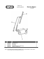
4
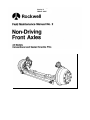
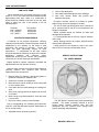
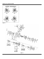
NON-DRIVING FRONT AXLES
CONVENTIONAL MODELS: 900, 901 AND 970
SEALED KNUCKLE PINS AND PERMANENTLY LUBRICAT ED CROSS TUBE MODELS: 921, 931, 932, 933,
934 AND 971
"EASY STEER" TM MODELS: 941 SERIES INCLUDES 941, 942, 943, 944
ALUMINUM BEAM MODELS: 931A SERIES INCLUDES 931-A AND 941-A
TUBULAR BEAM MODELS: 951, ALL FU SERIES AND FAE
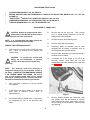
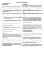
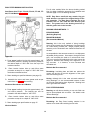
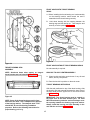
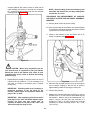
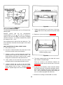
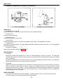
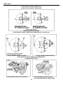
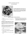
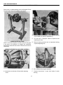
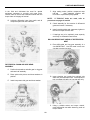
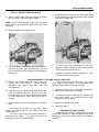
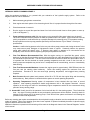
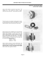
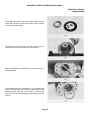
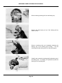
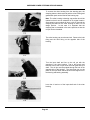
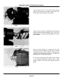
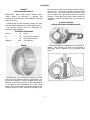
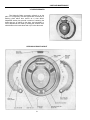
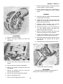
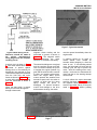
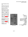
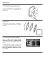
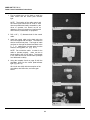
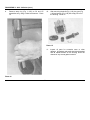
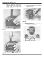
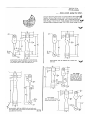
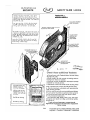
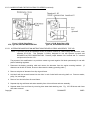
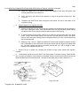
DISASSEMBLY - FRONT AXLE
CAUTION: Heating of components to aid in
disassembly is not allowed because it has a
detrimental effect on axle components.
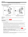
B.
Remove the hub cap from hub. Then, remove
jam nut, wheel bearing adjusting nut and lock
washers from knuckle spindle.
NOTE: It is recommended that safety glasses be
worn during disassembly and assembly.
C.
Remove the outer wheel bearing cone.
D.
Remove wheel and hub assembly.
E.
Disconnect brake air chamber lines on units
equipped with air brakes, or hydraulic lines on
units equipped with hydraulic brakes.
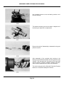
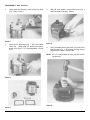
F.
Remove brake assembly from steering knuckle if
knuckles are to be rebuilt.
G.
If knuckles are to be rebuilt or tie rod to be
serviced, remove cross tube end nut and
disassemble cross tube assembly from cross tube
arm (Figure 1).
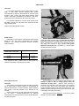
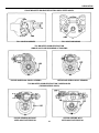
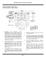
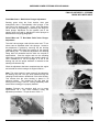
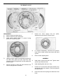
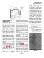
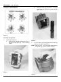
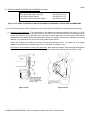
REMOVE THE STEERING KNUCKLE
A.
Jack up the front end of vehicle so that tires clear
floor. Block up securely at this position and
remove jacks.
CAUTION: To prevent the vehicle from
falling, do not disassemble or perform
knuckle repair with vehicle supported by
jacks only.
NOTE: The aluminum beam axle (FF-931-A) is
designed to allow jacking on the bottom surface of
the beam. UNDER NO CIRCUMSTANCES SHOULD
IT BE JACKED UNDER THE SPRING. Be sure to
jack up the aluminum beam with care to prevent
grooving or notching the lower surface of the beam.
Rockwell recommends the following procedures:
1.
Use a jack with a minimum of 10 tons (20,000
lbs.) capacity.
2
A jack with a low pick-up height of 8" should be
used with a minimum power raise of
approximately 5".
3.
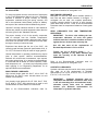
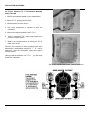
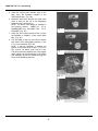
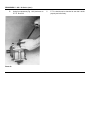
Figure 1
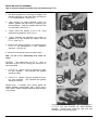
H.
The Walker 93660 or 93662 jacks, or equivalent,
are acceptable for use on the aluminum axle
beam.
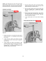
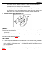
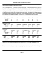
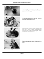
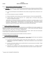
5
Remove steering knuckle cap capscrews, caps
and gaskets from top and bottom of knuckle.
Some models may have a welsh plug in place of
the lower king pin cap assembly. Remove snap
ring and plug.
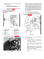
I.
Straight knuckle pins may be removed from the
bottom of the knuckle where adequate clearance
is provided; however, on some models such as
those with riveted backing plates, less work is
involved by tapping the knuckle pin out the top of
knuckle. In either case the adjacent parts, such
as air chambers, hydraulic lines or fittings, etc.
that might cause an obstruction to the knuckle pin,
must be removed first. Refer to brake manual for
brake disassembly.
Depending upon type of axle being serviced,
proceed as follows:
a.
Straight knuckle pin models (901, 921, 931,
941 and 951) continue from here.
b.
Tapered knuckle pin models (900, 910, 930
and 970) start on page 7.
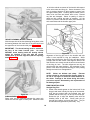
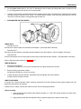
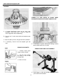
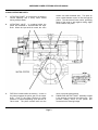
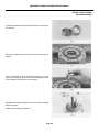
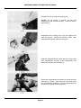
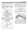
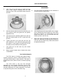
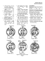
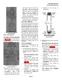
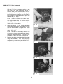
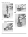
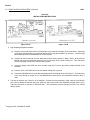
STRAIGHT KNUCKLE PINS
(901, 921, 931, 941, 951, 970 & 971
Series Models)
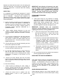
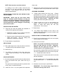
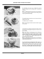
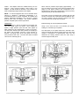
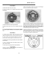
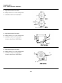
B.
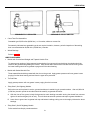
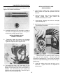
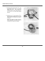
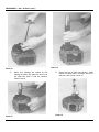
Draw Key Removal (Two per King Pin)
1.
Plain draw keys should be driven out
from the small end ("D" shaped) using a steel drift and a
brass hammer (Figure 4).
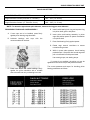
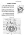
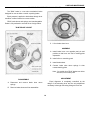
Figure 2
1.
2.
3.
4.
5.
6.
A.
Draw Key - Upper
Knuckle Pin
Knuckle BushingUpper
King Pin Cap
Shims
Draw Key - Lower
7.
8.
9.
10.
11.
Thrust Bearing
Expansion Plug
Expansion Plug
Lock Ring
Knuckle Bushing
Lower
Knuckle/Spindle
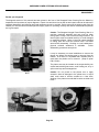
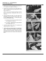
Figure 4
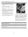
Straight Knuckle Pin Removal (Figure 3)
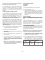
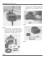
2.
Threaded draw keys (current model axles) should
be removed as follows:
a.
Loosen locknut and turn it out to the end of
the threads. The end of the nut should be
flush with the draw key end.
b.
With a brass drift and a hammer, firmly
strike the end of the nut to loosen the draw
key.
NOTE: Failure to strike the draw key
square may result in a damaged key
causing removal difficulties.
c.
Figure 3
6
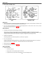
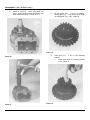
Remove the nut and key from the axle
center.
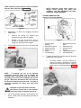
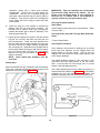
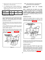
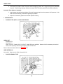
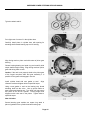
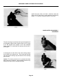
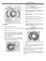
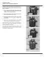
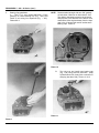
NOTE: Aluminum beam axles do not have machined
draw key flat on the king pin (Figure 5).
NOTE: Aluminum beam axles employ an
integral thrust bearing and lower seal
assembly. DO NOT SEPARATE THE SEAL
FROM THE THRUST BEARING.
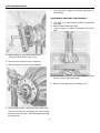
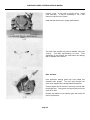
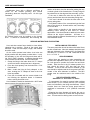
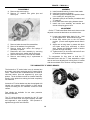
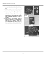
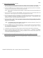
TAPERED KNUCKLE PINS
(900, 910, 930 and 970 Models)
Figure 5
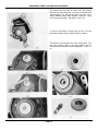
C.
D.
Disassembly of Draw Key Wedges Aluminum
Beam Axles
1.
Remove the locking nut, washers and
capscrew from the draw key wedges.
2.
Wedges can then be removed using a
wooden or rawhide mallet or by using the
prying slots provided on the wedges.
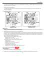
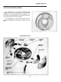
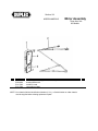
Figure 7
1. Knuckle Upper
Bushing
2. Knuckle Pin Sleeve
3. Upper Dust Cap
4. Knuckle Pin Nut
5. Shims
6. Thrust Bearing
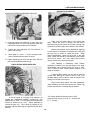
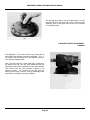
Tap out the knuckle pin by use of a bronze drift
(Figure 6).
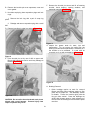
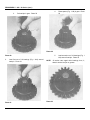
A.
7.
8.
9.
10.
11.
Tapered knuckle pins must be removed from the
bottom side of the knuckle.
1.
On some models it will be necessary to
remove the brake components to provide
clearance for knuckle pin removal. Refer to
brake manual for brake disassembly (Figure
8).
Figure 6
NOTE:
If bushings are not to be replaced
precautions must be taken not to damage the
bushings while removing the king pin. Grind off
any flaring on the end of the drift which will contact
the pin. Wrap tape around the drift 1/16" thick for
the first inch from the end of the drift. This step is
especially important for Delrin and easy steer
bushings.
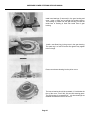
CAUTION: Do not strike these hardened
steel pieces directly with a steel hammer.
Personal injury from chips or splinters may result.
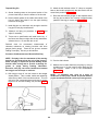
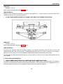
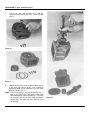
E.
Lift off the knuckle assembly, thrust bearing and
shims. Retain shims, thrust bearing and seal for
assembly.
Figure 8
7
Expansion Plug Lock
Ring
Expansion Plug
Knuckle Lower
Bushing
Tapered Knuckle Pin
Knuckle/Spindle
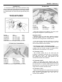
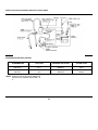
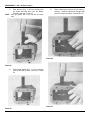
F. Remove the knuckle pin sleeve and lift off steering
knuckle, thrust bearing, spacing washers, and
backplate assembly (Figure 11).
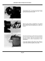
B. Remove the knuckle pin cover capscrews, cover and
cover gasket.
C. Knuckles employing lower expansion plugs and lock
rings:
1. Remove the lock ring with a pair of snap ring
pliers.
2. Dislodge and remove expansion plug with a small
drift.
D. Remove knuckle pin cotter key and nut (Figure 9).
Figure 11
G. Inspect the grease seals for tears, rips and
deterioration. Do not remove the seals from the
steering knuckle unless replacement is necessary or if
the knuckle is to be rebushed. If a seal must be
removed, pry it out with a screwdriver (Figure 12).
Figure 9
E. Drive knuckle pin out by use of drift on upper end.
Bronze drift should be used to avoid any damage to
threads (Figure 10).
Figure 12
H. Bushing Removal
1. Delrin bushings require no tools for removal
Bronze and Easy Steer bushings require a 5ton
press and a simple tool. See assembly section
for details. Fixture the knuckle rigidly with the
king pin hole vertical. Press the bushings out
slowly with frequent stops to check alignment of
the tool with the bushing bore and with the press
ram face.
Figure 10
CAUTION: Do not strike these hardened steel pieces
directly with a steel hammer. Personal injury from
chips or splinters may result.
8
PREPARATION FOR ASSEMBLY
RECONDITIONING OF
COMPONENTS
ROUGH PARTS
Rough parts such as cast brackets and some brake parts,
may be cleaned in hot solution tanks with mild alkali
solutions, providing these parts are not ground or
polished. The parts should remain in the tank long
enough to be thoroughly cleaned and heated. This will
aid the evaporation of the rinse water. The parts should
be thoroughly rinsed after cleaning to remove all traces of
alkali.
Repair or reconditioning of any front axle components is
not allowed. Rockwell strongly recommends replacement
of any component which is damaged or out of
specification. All of the major components are heat
treated and tempered and cannot be bent, welded, heated
or repaired in any fashion without experiencing a strength
or fatigue life reduction.
CAUTION: Exercise care to avoid skin rashes and
inhalation of vapors when using alkali cleaners.
This is a partial list of operations strictly prohibited on
front axle components. For further items or explanation
contact your local Rockwell Technical Representative.
DRYING
1. Welding of, or to, steering arms, tie rod arms, steering
knuckles, king pins, axle centers, tie rod assemblies,
hubs, drums or brakes.
Parts should be thoroughly dried immediately after
cleaning. Use soft, clean, lintless, absorbent paper towels
or wiping rags free of abrasive material, such as lapping
compound, metal filings or contaminated oil. Bearings
should never be dried by spinning with compressed air.
2. Hot or cold bending of spindles, steering arms, tie rod
arms, bull studs, axle centers or tie rod assemblies for
any reason.
CORROSION PREVENTION
3. Redrilling and bushing of axle center king pin holes.
Parts that have been cleaned, dried, inspected and are to
be immediately assembled, can be coated with light oil to
prevent corrosion. If these parts are to be stored for any
length of time, they should be treated with a good RUST
PREVENTIVE and wrapped in special paper or other
material designed to prevent corrosion.
4. Redrilling of draw key holes.
5. Spray welding of bearing diameters on spindles or in
machined bores.
6. Milling or machining of any component.
ALUMINUM BEAM GALVANIC
CORROSION PROTECTION
7. Relocation of tie rod clamps.
CLEANING
The following recommendations are for protection against
galvanic corrosion of the steel-aluminum contact points
on aluminum beam axles:
Parts having ground and polished surfaces such as
knuckle pins, knuckle pin sleeves, bearings and spindles,
should be cleaned in a suitable solvent such as kerosene
or diesel fuel.
Using an aluminum spacer between the steel spring and
the axle beam will eliminate galvanic corrosion on the
axle beam. If it is necessary for the steel spring to be in
direct contact with the aluminum axle, it is recommended
that the spring pad area be treated with a zinc chromate
paint. The entire spring pad, as well as the inner surface
of the dowel and U-bolt should be covered.
CAUTION: Exercise care to avoid skin rashes, fire
hazards and inhalation of vapors when using solvent
type cleaners. GASOLINE SHOULD NOT BE USED AS
A SOLVENT.
DO NOT clean these parts in a hot solution tank or with
water and alkaline solutions such as sodium hydroxide,
orthosilicates or phosphates.
The U-bolt should be. used with flat washers that are
cadmium plated and dichromate converted per Federal
Specification QQ-P-416, Type II. The clearance space
9
between the U-bolt and the holes in the axle spring pad
should be filled with a rust preventive compound, such
as.Texaco Compound L, to prevent water from standing
in this space.
IMPORTANT: Any indication of looseness in the total
steering linkage arrangement under normal steering
loads is sufficient cause to immediately check all
pivot points for wear, regardless of accumulated
mileage. Steering linkage pivot points should be
checked each time the axle assembly is lubricated.
INSPECTION
It is impossible to overstress the importance of careful
and thorough inspection of steering knuckle components
prior to assembly.
Thorough visual inspection for
indications of wear or stress, and the replacement of such
parts as are necessary, will eliminate costly and avoidable
front end difficulties.
TIE ROD AND TIE ROD END
INSPECTION
A.
A. Inspect the steering knuckles, king pins, steering arms
and tie rod arms and replace if indications of
weakness, cracks or excessive wear is found. Cracks
can be located by die check, magnetic particle or
fluorescent particle inspection performed by a
qualified technician.
B.
C.
IMPORTANT: Rockwell does not recommend
attempts to salvage damaged ends by repacking and
replacing the boot seal on non-greasable ends.
Check spindle bearing diameters for size and
condition. Replace spindle if bearing diameters are
under specification, discolored from heat or severely
scored.
B. 1. Check the turning torque value between the ball
stud and the ball cavity. If torque value is less
than five (5) inch pounds, the cross tube end
assembly should be serviced.
If tie rod arm or steering arm has been removed,
inspect tapers for fretting pits. If the tapered hole in
the knuckle is fretted and pitted replace both the
knuckle and the arm. If only the arm taper is fretted,
replace only the arm.
2. No lateral or vertical movement should be found in
any tie rod assembly when checked by hand.
Leverage or prying with a tool can produce
vertical movement in most tie rod ends which is
inherent in their design.
Use of tools for
checking free play is not recommended.
D. If the king pin has worn through the bushing and into
the knuckle, replace the knuckle.
3.
E. Check the tightness of the steering connections such
as cross tube arms, steering arm, etc.
F. For units with sealed knuckle pins, check knuckle pin
seal for rips, tears and excessive wear. Do not
remove the seals from the steering knuckle unless
replacement is necessary or the knuckle is to be
rebushed.
G.
J.
Permanently lubricated and extended lube end
assemblies should be replaced if found below
specifications. Serviceable models should be
rebuilt.
C. Any tie rod tubes found to be cracked, bent, dented or
severely gouged should be replaced.
REBUILDING TIE ROD END ASSEMBLIES
Remove the thrust bearing seal from the thrust
bearing case and inspect the seal for wear, rips and
tears. On aluminum axles with integral seals, do not
remove seal.
Some older models contain tie rod assemblies which are
rebuildable. These are however limited in the number of
rebuilds. A determination must first be made of the
condition of the socket forging. Those excessively worn
must not be used again, but replaced. These can be
replaced with new rebuildable or non-rebuildable end
assemblies.
H. Check thrust bearing.
1.
Check seals visually for any indication of damage,
also check to make sure that the seal is securely
seated on the socket. If the cross tube end has a
grease fitting, replace damaged seals. Ends not
having greasing provisions, the entire tie rod end
should be replaced if seals are damaged or loose.
Check knuckle pin bushings for wear, flaking or
scoring. Compare diameter with correct specification,
if the bushing diameter is .010" greater than the new
bushing dimension, replace the bushings.
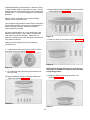
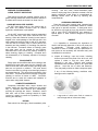
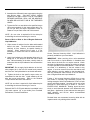
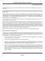
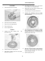
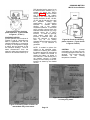
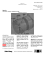
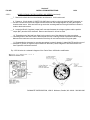
WHEEL BEARING INSPECTION
Wheel bearings should be very closely inspected at the
time of knuckle inspection or when knuckle repair is being
made.
Check axle center bore for condition and size.
Replace center if bore is .001" greater than
specification.
10
Inspect wheel bearing cones and cups. Replace if rollers
or cups are worn, pitted or damaged in any way. If wheel
bearing cups are to be replaced, remove from hubs with a
suitable puller. To avoid hub damage don't use drifts and
hammers.
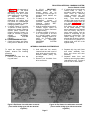
3. Bright rubbing marks on the dark phosphate surfaces
of the bearing cage (Figure 15).
Remove all the old grease from the wheel bearings,
spindle, hub cavity, and hub cap.
(The old grease may contain moisture which would lead to
an early bearing failure if not removed.) Use kerosene or
diesel fuel and a stiff brush. Gasoline and heated
solvents should be avoided.
Allow the cleaned parts to dry, or dry them with a clean
absorbent cloth or paper. Clean and dry hands and all
tools used in the service operation. Grease will not
adhere to a surface which is wet with solvent, and solvent
may dilute the lubricant.
Figure 15
4. Etching or pitting on functioning surfaces (Figure 16).
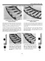
Bearings must be replaced if any of the following
conditions exist:
1. Large ends of rollers worn flush to recess or radii at
large ends of rollers worn sharp (Figure 13).
Figure 16
Figure 13
NOTE: Repeat bearing failures are a result of out of
round hubs or spindles or indicate a poor assembly
or adjusting practice.
2. (a) Visible step wear, particularly at the small end of
the roller track.
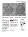
5. Spalling or flaking on bearing cup and/or cone
surfaces (Figure 17).
(b) Deep indentations, cracks or breaks in bearing cup
and/or cone surfaces (Figure 14).
FIGURE 14
Figure 17
11
(aluminum alloy 7075-T73 or 7075-T76) with an
interference fit of .000" to .003". The bushing should be
shrunk by freezing prior to installation in the enlarged
hole.
Pressing the bushing into place at ambient
temperature is not recommended.
Under no
circumstances should the axle center dowel hole be
expanded by heating during installation of the bushing.
REPAIR AND CHECK
PROCEDURES FOR ALUMINUM
BEAM AXLES
Rockwell disapproves of heating, welding, bending,
altering or drilling the aluminum axle center.
Repair of the spring seat howl hole is permitted, if
necessary. Our recommendation is to drill out the dowel
hole so that the new diameter is no more than .5" larger
than the original diameter. Install an aluminum bushing
NOTE: If brakes require service, refer to RKc6kwell
Field Maintenance Manual No. 4 for CamMaster,
Brakes. (Also Disc.)
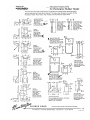
ASSEMBLE FRONT AXLE
REPLACEMENT OF BRONZE OR
STEEL BACKED BRONZE
STEERING KNUCKLE BUSHINGS
B. The new bushings will be installed with the same tool.
The pilot of this tool prevents collapse or distortion of
bushing during installation.
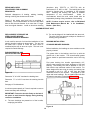
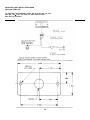
A tool used for removal of old and the installation of new
steering knuckle bushings is shown below. The tool can
be made from a piece of round bar stock which is
machined with a step to serve as a pilot. This tool is not
required for Delrin bushings.
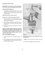
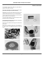
BUSHING INSTALLATION
STANDARD BRONZE BUSHINGS
Before installation, the bushings on some models must be
properly oriented.
BUSHING REMOVAL AND
INSTALLATION TOOL (Figure 18)
The grease hole in the bushing must line up with the
grease hole in the knuckle. The circumferential grease
groove should be positioned toward the end of the king
pin.
First press bushing into knuckle approximately 1/8",
relieve press pressure and check alignment of tool and
bushing. The bushing can now be pressed in until it is
flush with the top machined surface of the knuckle. For
those designs that have king pin seals, the bushing can
be pressed in until it is .135" to .165" from the inside
machined surface of the knuckle. This applies to both
upper and lower bushings. Do not install seals until after
the reaming operation is completed (Figure 19).
Figure 18
Dimension "X" is 0.010" less than the bushing bore.
Dimension "Y" is 0.010" less than the steering knuckle
bore.
See page 15 for dimensions.
A minimum press capacity of 5 tons is required to remove
bronze and easy steer bushings.
IMPORTANT: Fixture the knuckle firmly on the bed of
the press to avoid knuckle slippage during bushing
removal or Installation.
A. The worn bushings are pressed out of the knuckle,
employing tool shown.
Figure 19
12
EASY STEER BUSHING INSTALLATION
For all other models follow the bronze bushing sealed
king pin design installation procedure for installation and
use chart page 15 for new bushing diameter.
Steel Beam Axle FF-941, FG-943, FG-941, FF-942, FF943, FF-944 Models (Figure 20)
NOTE: Easy Steer retrofit kit may contain king pin
seals which are not part of the original design of the
axle assembly. The Easy Steer bushings are to be
installed .135" to .165" from the inner knuckle yoke
faces. The grease hole in the bushing must line up
with the grease hole in the knuckle.
BUSHING SIZING METHODS D
ELRIN BUSHINGS
(No Sizing Required)
BRONZE BUSHINGS
(Recommended Method)
Reaming -this is the only method of sizing bushings
which gives accurate size and alignment of bores as good
as a new factory finished part. Single purpose piloting
reamers per the illustration and charted dimensions are
the best.
An acceptable but less accurate reamer is a multipurpose
adjustable piloting reamer. One reamer, through trial and
error, can accurately be sized to fit several axle sizes.
This is not a preferred method since the cutter cannot be
gaged for diameter and bushing bore alignment is not
very accurate. It is however, a more universal and
affordable tool.
Figure 20
A. Press upper bushing into knuckle approximately 1/8"
and relieve pressure. Bushing can now be pressed to
the desired depth of .352"1.382" from the top of the
machined surface.
B.
Methods Not Recommended
Place knuckle bottom side up and follow same
procedure as step #1 to a depth of .352"1.382" from
the bottom machined surface.
Burnishing- burnishing bars and balls are seldom the
correct size and do not provide alignment of the upper
and lower bushing bores.
C. Ream bushings to specified diameter (see page 15).
Honing -although this is the most universal method of
sizing bushings, it is not recommended because it does
not provide good bushing bore alignment. Bushing bore
size is good with this method.
D. Assemble the upper and lower grease seals as per
instructions on page 16 after reaming.
Aluminum Beam Axles 941-A Models
EASY STEER BUSHINGS
A. Press upper bushing into knuckle approximately 1/8"
and relieve pressure. The bushing can now be
pressed to the desired depth of .445"1.475".
B.
Reaming -as with bronze bushing, a new axle finish can
only be accomplished with a reamer. See details under
"Bronze Bushings."
Place knuckle bottom side up and follow same
procedure as step #1 to a depth of .290"1.320".
Methods Not Recommended
Burnishing- the Easy Steer bushing material is too
resilient to be sized with burnishing bars or balls.
C. Ream bushings per specifications on page 15.
All other Models
13
Honing -this method does not work well with the Easy
Steer bushing material and does not provide proper
alignment of the bores. This can be used as a last resort
but must be done dry (no lubricant) and with new stones.
4.
After the reamer sizes most of the upper bushing,
support the reamer so that it does not drop to the
bottom bushing as it completes the cut.
5. After the upper bushing has been sized, gently slide
the reamer through until it engages the bottom
bushing. Repeat steps 3 and 4 for the bottom
bushing.
REAMING PROCEDURE
REAM UPPER BUSHING FIRST (Figure 21)
6. Slide the reamer out through the bottom. If the reamer
must be pulled back up through the bushing do so
only while rotating the reamer in reverse. Any other
way will damage the bushings.
7.
Clear bushing debris from bores before installing
seals.
REAM LOWER BUSHING SECOND (Figure 22)
Figure 21
1. Position the knuckle in a vise with soft metal shims to
protect the knuckle. It is preferable to have the king
hole vertical.
2.
Gently slide the reamer pilot through the upper
bushing until the reamer cutters begin to engage the
upper bushing.
3.
Begin rotating the reamer and applying a light
downward pressure with your hand at the same time.
Do not force the reamer by applying too much
downward force. The reamer can be rotated at any
speed but should be done smoothly.
Figure 22
14
REAMING SPECIFICATIONS
NOTES: (1)
required.
On Models equipment with Delrin bushings, the reamer and the removal/installation tool are not
15
GREASE SEAL INSTALLATION
IMPORTANT: Do not install seals until bushings have
been reamed; seals will be damaged during reaming.
BRONZE BUSHING KNUCKLES
A.
Place steering knuckle bottom side up in a vise
equipped with soft metal protectors. Position upper
knuckle boss (top end down) between jaws of vise
and lock securely.
NOTE: Seals must be oriented as shown.
Reversal of a seal will prevent purging of grease.
B. With the top end of the knuckle held firmly in this
position, place the seal over the knuckle counterbore,
with the rubber lip facing up.
C. Using a suitable sleeve and a bronze drift, tap the seal
into the knuckle until it bottoms against the bushing or
counter bore.
D. Repeat this procedure by reversing the knuckle for the
lower seal.
NOTE: In the absence of a suitable driver, do not tap
the seal in with a hammer. See the seal in the
opening and cover it with a rigid flat metal plate. Tap
the plate with a hammer directly over the seal until
the seal is flush with the machined surface. Do not
drive the seal any further.
EASY STEER BUSHING KNUCKLES
Figure 23
A. Follow instructions for bronze bushed knuckles A, B
and C.
EASY STEER RETROFIT INTO NON-SEALED AXLE
DESIGNS ONLY
B. Using a suitable sleeve and a bronze drift tap the seal
into the knuckle bore until it is flush with the machined
surface as shown in Figure 23.
A. A driver is required to position the seals in the knuckle
bore.
B. Position the seals against the bushings as shown.
16
FRONT AXLES WITH THRUST BEARING
SEALS
A. Before installing the thrust bearing and seal assembly
on the steering knuckle, make certain the seal is
assembled to the thrust bearing correctly.
B.
Hold thrust bearing with the opening between the
bearing cage and the retainer up. Then snap the seal
securely over the opening (Figure 26).
Figure 26
Figure 24
FRONT AXLES WITHOUT THRUST BEARING SEALS
THRUST BEARING SEAL
ASSEMBLY
No sub-assembly is required.
KNUCKLE TO AXLE CENTER ASSEMBLY
NOTE: Aluminum beam axles employ an integral
thrust bearing and seal assembly (Figure 25).
A. Clean knuckle and axle center bores of any dirt and
debris, and dry components.
B. Place the knuckle in position on the axle center.
THRUST BEARINGS WITH SEALS
With the seal positioned on top of the thrust bearing, slide
the bearing and seal assembly between the lower face of
the axle center and the upper face of the lower knuckle
yoke (Figure 27).
Figure 25
IMPORTANT: The thrust bearing must be seated on
the upper face of the lower knuckle yoke. On axles
WITH thrust bearing seals the seal must always cover
the opening between the bearing cage and retainer.
Always install the bearing and seal assembly in the
axle with the seal on top (Figure 27).
NOTE: Some of the thrust bearings used in front
axles have the word "TOP" stamped on the flat face
of the bearing retainer. The stamped word "TOP"
should NOT be used for bearing installation
purposes. Refer to the following instructions for
proper bearing positioning.
17
to limit the vertical movement of the knuckle with respect
to the axle center and king pin. Some clearance in this
area is required however to allow grease to purge from
the upper bushing area. Carefully inspect shims, new or
used, to be sure none are kinked, bent or torn. Discard
any that are damaged. Select a quantity of shims to
obtain as little vertical end play as possible. Lift the
knuckle in position and slide the shim pack between the
axle center boss and the knuckle upper yoke.
Figure 27
THRUST BEARINGS WITHOUT SEALS
With the open side of the thrust bearing facing down, slide
the bearing between the lower face of the axle center and
the upper face of the lower knuckle yoke (Figure 28).
IMPORTANT: The thrust bearing must be seated on
the face of the lower knuckle yoke.
On axles
WITHOUT thrust bearing seals the bearing should
always be installed in the axle with the closed
retainer face up and the cage face (with the opening)
down (Figure 28).
Figure 29
Alignment of the king pin hole in the knuckle and axle
center is now required for king pin installation. While
looking down through the king pin hole, shift the knuckle
to align it with the axle center. Now align the shims to be
flush with the axle center around the entire circumference
of the king pin hole. The shim alignment can only be
done through the upper bushing. Any protrusion of any
portion of the shim will prevent the king pin from passing
through and result in a damaged shim.
NOTE: Shims are delicate and sharp. Extreme
caution should be exercised while aligning shims so
as not to cut fingers or bend the Inside diameter of
the shims. Damage to the shims during this entire
procedure requires disassembly and replacement of
the damaged parts.
KING PIN INSTALLATION
Straight King Pins
A. Smear clear chassis grease on the bottom half of the
king pin and insert it slowly into the top of the knuckle.
King pins are marked with the Rockwell logo, part
number and the word “top" on the top end of the pin.
Rotate the pin to align the drawkey slots with the
drawkey holes in the axle. Slowly push the pin
through the bushing, seal and shim pack. The pin
should slide through the shim pack freely. Any
Figure 28
SHIM ASSEMBLY (Figure 29)
Shims must now be positioned between the upper axle
center face and the upper knuckle yoke. Shims are used
18
resistance greater than a hand push indicates
misalignment. Remove the pin and realign the
components. After the pin is inserted through the
shim pack a brass hammer may be used to assist in
installation. Care must be taken not to dislodge the
lower grease seal as the king pin enters the lower
knuckle yoke.
B.
IMPORTANT: Both the threaded and non-threaded
keys must be solidly seated in this manner. The nut
torque on the threaded design is only sufficient to
hold the key in position and is not adequate to
properly seat the key (except aluminum axle).
Securing Threaded Drawkeys
(Steel Axles)
Center the king pin in the knuckle to equalize the
distance fr6m the top and bottom surfaces. For
knuckles with a bottom welsh plug arrangement,
increase the bottom gap to allow for assembly of the
welsh plug and snap ring.
Install flanged locknut and torque to specification. (Refer
to torque chart. )
Securing Double Key With Through Bolt (Aluminum
Axles)
C. Lightly tap the drawkeys into position, flat side toward
king pin; do not firmly seat them until after the end
play measurement. Install the lower drawkey from
the front side and the upper drawkey from the rear.
Aluminum axles use a double drawkey arrangement
with a through bolt. Assemble so the wedged ends of
the two keys contact the king pin and torque to restrict
pin from moving while the end play is measured.
Measure end play per procedure on page 21 and
adjust if necessary.
NOTE: Never install both drawkeys from the
same side.
Torque to specification.
Securing Plain Drawkeys
Plain drawkeys are secured by staking with a pointed
punch and must therefore be only slightly below the
forged surface of the axle center. King pin kits are
supplied with three different length upper (shorter) and
lower (longer) drawkeys.
The seated drawkeys should be 1/32" minimum to 1/8"
maximum below the forged surface of the axle center
boss. If the key falls out of this range, drive it out and
replace it with the appropriate size.
Seating Keys
After the specified end play is obtained, seat the drawkeys
firmly with a hammer and drift all except aluminum axle
which does not require seating (Figure 30).
Use a sharp pointed steel punch to indent the forging in 3
places around the drawkey hole (Figure 31). This partially
collapses the hole and wedges material against and
behind the drawkey to prevent the key from backing out.
Figure 30
Figure 31
19
B. Attach the dial indicator with a "C" clamp or magnetic
base to the knuckle spindle such that the knuckle can be
turned freely as shown (Figure 33).
Tapered King Pin
A. Smear chassis grease on the tapered section of the
pin and insert the pin from the bottom of the knuckle.
C. Place the dial indicator plunger on the exposed end of
the king pin so that its line of action is approximately
parallel to the king pin center line (Figure 33).
B. Smear chassis grease on the inside and outside of the
king pin sleeve and insert it into the upper bushing
bore over the king pin.
C. Install king pin nut, and torque only enough to seat the
king pin for end play measurement.
D.
Measure end play per procedure on page 21 and
adjust if necessary.
E. Torque nut to specification and install cotter key. If
the cotter hole does not align with the nut castellation,
advance the nut. Do not back the nut off.
Rockwell does not recommend measurement of
clearance tolerances on steering knuckles with shim
gauges (feeler gauge). These will not give an accurate
reading of end play. Use only a dial indicator.
Procedure for Measurement of Knuckle End Play
Figure 33
NOTE: End play is the free movement of the steering
knuckle up and down along the axis of the king pin.
Some end play is required to prevent binding of the
knuckle while turning and to provide a passage for
grease to purge during bushing lubrication.
Excessive end play can cause interference between
the king pin and end caps or retainers.
D. Zero the dial indicator.
E. Measure the knuckle clearance (end play) by using a
suitable lever to lift the knuckle while observing the
dial indicator. Make a note of the measurement
(Figure 34).
A. With king pin caps off, turn the knuckle to the straight
ahead position. Take a rubber mallet and repeatedly
strike the top draft of the knuckle as shown. This will
shift all of the components down and remove grease
layers so an accurate reading may be taken (Figure
32).
NOTE:
A protective pad, such as a piece of
cardboard or heavy tape, should be placed between
pry bar and aluminum axle center to prevent grooves.
Figure 32
Figure 34
20
A small hydraulic jack under a block of wood can be
used beneath the knuckle to provide the necessary
lift. Keep lifting the knuckle until the dial indicator
reading levels off (Figure 35).
NOTE: Normal seating of the thrust bearing, seal
and shims will increase the end play reading after
a short time in service.
PROCEDURE FOR MEASUREMENT OF KNUCKLE
AND END PLAY WITH TIRE AND WHEEL ASSEMBLY
MOUNTED:
A. Securely block vehicle to prevent rolling.
B. Place a jack under the axle beam as close as possible
to the knuckle end being checked and jack the vehicle
up until the tire is clear of the floor.
C. Attach a dial indicator to the axle beam with a "C"
clamp or magnetic base (Figure 36).
Figure 35
CAUTION: When using a hydraulic jack, be
sure that the axle is supported by two jack stands.
Raising the end in this manner may cause an axle
supported only in the -center to tip and fall causing
personal injury.
F. Repeat Steps A through E with the knuckle in the full
right and left turn positions. This is necessary to be
sure that no binding or excessive play is present
during turns.
Figure 36
D. Place the dial indicator plunger on top of the king pin
cap or knuckle forging so that its line of action is
approximately parallel to the king pin center line.
IMPORTANT: If binding exists or zero end play is
measured anywhere in the full travel of the
knuckle, remove shims as required to obtain end
play of .001" to .025".
E. Zero the dial indicator.
F. Measure the knuckle clearance (end play) by using a
suitable lever to lift the knuckle while observing the
dial indicator. Make a note of the measurement. On
axles in service, the end play may increase to a
maximum of .065" (1.70 mm) at which time it will be
necessary to re-shim end play back to .001 "-.025"
(.02-.64 mm)
IMPORTANT: After measuring knuckle clearance
(end play) of over .025" add shims between upper
knuckle pin boss and axle center end, as
required, to obtain an end play of .001"-.025" (.02.64 mm) through full range of turn.
21
NOTE: Both knuckles should be checked.
where used.
If a reading of over .065" is taken, remove the tire
and king pin cap and remeasure as per rebuild
procedure. If the reading is still over .065" then
reshim to specifications.
C. Install the felt, retainer and lock ring on the protruding
straight pins that are not provided with covers or caps.
GREASING PROCEDURE
INSTALLATION OF KING PIN CAPS, WELSH PLUGS
AND RETAINERS
IMPORTANT: Before king pin caps and/or welsh
plugs are Installed recheck drawkeys and king pin
nut to be sure the final staking or torquing procedure
has been completed. Omission of the final king pin
securing steps may result in damaged or broken king
pins and axle centers.
A.
Grease upper bushing first then lower. (Grease
specification 617 A or B). If grease does not flow
through the thrust bearing it will be necessary to raise
the knuckle with a jack to close off passage of grease
around the thrust bearing.
Regrease the lower
bushing and thrust bearing then remove jack.
B.
Rotate knuckle lock to lock to help distribute the
grease. Note the knuckle will now be noticeably
harder to rotate than during the end play
measurement. This is normal.
KING PIN CAPS AND COVERS
A.
C. Repeat step 1.
Align king pin caps and gaskets and assemble to
knuckles with capscrews and washers.
D.
1. Gaskets do not have a top or bottom orientation
and may be installed in either position.
INSTALLATION OF STEERING AND TIE ROD ARMS
2. Caps do require orienting the flat side toward the
gasket and knuckle.
The flat, sealing side
contains no numbering or lettering.
A. Press fit key into steering arm and tie rod arm keyway
near the small end of the taper.
B. Torque fasteners to specification.
B. Insert arms into knuckle.
WELSH PLUGS
NOTE: It is possible to mistakenly reverse the left
hand and right hand tie rod arms. Distinction
between left and right arm can be made by
visualizing the tie rod assembly position.
A. Place welsh plug into the lower knuckle bore with the
rounded (convex) side toward the king pin.
B. Install lock ring.
C.
On models using drawkeys fill the voids in the
drawkey holes with grease to prevent corrosion and
ease future disassembly.
On center point models FE970 and FF971 the tie rod
ball stud is assembled into the arm from the top side;
i. e. , the ball stud is above the arm.
On models not grooved for lock rings, secure the
plugs in place by staking in four equally spaced
places.
KING PIN RETAINERS
This is also true for FU series axles with tie rod ends
that are rebuildable.
A. On units employing grooved knuckle pins that protrude
below the knuckle lower yoke, install lock ring in
groove.
All other models have tie rod assemblies that install
from the bottom side; i. e. , the ball stud is below the
arm.
C. Assemble nuts and torque to specification.
The upper ends of steering knuckle are protected with
covers, caps, or retainers and felts.
IMPORTANT: The correct torque range must be
reached on steering arms and tie
B. Install the cover or cap and gasket with capscrews
22
GENERAL WHEEL BEARING
ADJUSTMENT
ASSEMBLY
rod arms. Torques below minimum will not seat the
tapers properly and reduce service life.
D. Install cotter keys. If the cotter hole does
with the nut castellation, advance the nut to
castellation. Do not exceed the maximum
torque value. Do not back nut off for cotter
alignment.
not align
the next
specified
key hole
A. Assemble bearings and hub on the axle spindle.
B. Install thrust washer, if used.
C. Install the wheel bearing adjusting nut. Thread the nut
against the bearing or thrust washer. Be sure there is
sufficient clearance between the brake shoe and drum
so brake shoe drag will not interfere with the bearing
adjustment.
TIE ROD ASSEMBLY AND INSTALLATION
Tie rod assemblies with straight tubes contain left hand
threads on one end and right hand threads on the other.
These mate with similarly threaded tie rod ends. The
ends therefore are not interchangeable. This type of
assembly does not require removal from the arm for toein adjustment and provides very fine adjustment.
SEATING BEARINGS
NOTE: It is recommended that a torque wrench be
employed for assembly of the adjusting nut and jam
nut.
Tie rod assemblies with drop center tube contain coarse
pitch threads on one side and fine pitch on the other.
Ends for these are also not interchangeable. This type of
assembly requires removal from the tie rod arm for
adjustment since the drop center tube cannot be rotated.
The differences in thread pitch provide a finer adjustment
range for setting toe-in.
Tighten the adjusting nut to 100 lb. ft. torque while
rotating the wheel in both directions to be sure all bearing
surfaces are in contact. Loosen the nut completely and
then re-torque to 50 lb. ft. while rotating the wheel.
FINAL BEARING ADJUSTMENT
The final bearing adjustment is designed to result in .001"
to .010" end play. Always be sure that this end play has
been obtained after the jam nut has been torqued or when
the cotter pin has been installed.
A. Thread end assembles into tube equally on both sides
to the approximate overall length required.
B. Torque clamp lock nuts to specification.
IMPORTANT: Failure to obtain end play as specified
will cause bearing overload and premature failure.
C. Assemble tie rod assembly into the tie rod arms on the
axle assembly.
D.
Torque the end assembly nuts to specification and
install cotter key.
E.
If cotter pin hole does not align with the nut
castellation, advance to the next castellation and
install pin. D6 not exceed the maximum specified
torque while doing this. Do not back nut off to align
the cotter hole.
A. For axles that have single nut construction, back off
adjusting nut 1/6 to 1/8 turn. Install cotter pin and
measure end play, adjusting if necessary.
B. For axles that have double nut and lock construction,
back off adjusting nut 1/4 to 1/3 turn. Assemble
wheel bearing lock ring if used, jam nut lock and jam
nut. Tighten jam nut to torque specified below.
Measure end play and adjust if necessary.
LB. FT. TORQUE
NUT SIZE
MIN.
MAX.
1-1/8" to 2-5/8"
100
150
2-5/8" and over
100
200
NOTE: If tie rod end assemblies, tie rod tubes or
tie rod arms have been removed or replaced, toe
in must be checked and readjusted.
23
C. Bend the jam nut lock over the jam nut and over the
adjusting nut if no lock ring is used.
D.
NOTE: Do not adjust the turn angle beyond that
specified by the vehicle manufacturer.
For assemblies using a dowelled adjusting nut,
pierced lock washer, and no jam nut lock washer
torque jam nut as follows, measure end play and
adjust if necessary.
NUT SIZE
1-1/8" to 2-5/8"
2-5/8" and over
MIN.
200
250
POWER
STEERING
ADJUSTMENT
GEAR
(OR
CYLINDER)
NOTE:
Rockwell does not approve any power
steering system without provision for pressure relief
or positive mechanical stop to be set BEFORE
maximum turn angle Is reached. The power must be
cut off or reduced substantially ahead of the axle
stop to prevent unnecessary stressing of the axle
components.
LB. FT. TORQUE
MAX.
300
400
STEERING STOP ADJUSTMENT
MECHANICAL RELIEF
All Rockwell axles are delivered with steering stop screws
preset. Adjustments are often made by the vehicle
manufacturer to accommodate various chassis designs
and tire sizes. steering stop adjustments on new vehicles
are therefore not required.
Vehicles with mechanical Pitman arm stops or assist
cylinder stops should be adjusted to end the travel of the
Pitman arm or cylinder 1/8" before the steering stop screw
would contact the axle boss (Figure 38).
These adjustments of both axle steering stops and power
steering unit should be periodically checked and corrected
if necessary.
The stop adjustment should be checked and corrected
any time any part of the steering system is disassembled,
replaced, added or adjusted.
Adjust the left and right knuckle steering stops to contact
when the maximum turning angle of the specific axle is
reached, and lock with jam nut (Figure 37). Refer to
torque chart on page 24.
Figure 38
Maximum turn angle will then be determined by the arm
or cylinder stop and not the axle stop. This must be done
for full left and full right turns.
HYDRAULIC RELIEF
Hydraulic steering gears equipped with poppet valves
should be adjusted while a 1/4" to 3/16" spacer is held
between the axle stop pad and stop screws. The poppet
valves should be adjusted to allow pressure bypass at this
position with spacer in place in full left and right turn
positions. During this setting the steering gear pressure
should be at a minimum, 600 psi or less (Figure 39).
Figure 37
24
Figure 40
Figure 39
TOE-IN RECOMMENDATIONS
The following recommendations are for all Rockwell front
steering axles.
F.
Rockwell concurs with the tire manufacturer's
recommendation of 1/16"
1/32" toe-in for bias ply or
radial ply tires with the weight of the empty (unloaded)
vehicle on the axle. For vehicles measured fully loaded
the ,setting is 1/32" ± 1/32".
Position the trammel bar at the front of the tires.
Adjust scale end so that pointers line up with scribe
marks.
G. Read toe-in (or toe-out) from scale (Figure 41).
Do not measure toe-in with the front axle jacked up. The
toe-in should be measured with the weight of the vehicle
on the axle.
MAKE SURE VEHICLE IS ON A LEVEL FLOOR
A. Jack up the front axle.
B. Use paint or chalk and whiten the center area of both
front tires around the entire circumference.
C.
D.
E.
Position a scribe or pointed instrument against the
whitened part of each tire and rotate the tires. The
scribe must be held firmly in place so that a single
straight line is scribed all the way around the tire.
Figure 41
H. The same measurements can be made with a steel
tape measure at spindle height.
Lower vehicle on floor and then move the vehicle
backward and then forward approximately ten feet.
Toe-in (or. toe-out) is the difference between the
measurement taken at the front and rear of the tires
(Figure 41).
Position trammel bar at rear of tires and adjust
pointers to line up with scribe lines and lock in place
(scale should be set on zero). Pointers must be
raised to spindle height on the tire as shown (Figure
40).
I If an adjustment is necessary, loosen cross tube clamps
and rotate cross tube as required and tighten clamps.
Move vehicle backward and then forward about 10
feet. This is particularly important when setting the
toe-in on vehicles equipped with radial tires.
J. Recheck toe-in setting to make SURE it is correct.
25
NON-DRIVING FRONT AXLE CAMBER SPECIFICATIONS
FF FG FL Series
CONDITIONS
1. Camber angles machined into axles.
• less hubs.
• axle not mounted under vehicle.
• no load.
2. Camber angles of axle equipped with hubs.
• axle not mounted under vehicle.
• no load.
LEFT (DRIVER'S) SIDE
+3/4°nominal
RIGHT SIDE
+ 1/4°nominal
+ 3/4°(± 7/16°)
or
+1-3/16°to +5/16°
(final reading)
+11/16°to -3/16°
(final reading)
+1/4°(±7/16°)
or
+11/16°to -3/16°
(final reading)
+3/16°to -11/16°
(final reading)
+ 13/16°to -1/16°
(final reading)
+ 5/16°to - 9/16°
(final reading)
3. Camber angles of FF-931, FF-941, FL-931 and
FL-951 axles under rated load.
• axle mounted under vehicle.
4. Camber angles of FF-931A and FF-941A aluminum
beam axles under rated load.
• axle mounted under vehicle.
IMPORTANT: Camber is not adjustable. ROCKWELL DOES NOT APPROVE OF CHANGING THE CAMBER
ANGLE OR BENDING OF STEEL OR ALUMINUM BEAMS. Bending the axle beam to alter camber angles is
detrimental to the integrity of the axle beam.
If camber angles, of models mentioned, do not meet specifications shown in the chart, contact your area Rockwell
Technical Service Representative for assistance.
Most other models have a + 10 nominal camber on the left and right sides, for condition #1. Conditions #2 and #3 are
proportionally higher.
CASTER
Caster settings are determined by the vehicle manufacturer; generally, manually steered vehicles operate best at 1°to 21/2°positive caster. Power steered vehicles are generally set between 2°and 4-1/2°positive caster.
Center point models FE970 and FF971 are the only exceptions. These operate best at 1/2°to 2°caster.
16900 and 17100 series axles have + 30 caster machined into the axle center. All other models must be adjusted for the
caster at assembly.
For maximum steering effort reduction, easy steer axles should be set at 10 positive caster.
26
TROUBLESHOOTING GUIDE
1a. Rapid or Uneven Tire Wear
•
Incorrect toe-in setting
•
Improper tire inflation
•
Unbalanced tires
•
Improper Ackerman steering geometry
•
Tandem alignment
Severely contaminative environment
•
Failure of protective rubber boot
4. Bent or Broken Cross Tube, Broken Ball Stud, Bent or
Broken Steering Arm or Cross Tube Arm
b. Toe-in Control
•
•
When setting toe-in, it is important to neutralize
the component and tire deflections by backing up
and then going forward and rechecking the toe-in.
This is especially important with radial tires. The
check and possible re-set should be followed
even if bearing plates are used.
•
Excessive power steering system pressure
•
Misadjusted power steering cut-off
•
Operational (curbing)
•
Improper installation of add-on power steering
5. Heavily Worn or Broken Steering Arm Ballstud
2. Hard Steering
•
Over tightened draglink
•
Inadequate or improper lubrication
•
Misadjusted power steering stops
•
Low power steering system pressure
•
Improper assembly of steering gear box
•
Worn or missing seals and gaskets
•
Inadequate or improper lubrication of knuckle pins
•
Improper type of grease
•
Inadequate mechanical advantage of steering
system in steering box ratio, lengths of pitman
arm and steering arm
•
Inadequate lubrication frequency
•
Improper lubrication technique
•
Improper caster
•
•
Tight draglink or tie rod ends
Inadequate lubrication frequency due to extreme
operating conditions such as abrasive dust and
sandy environments
•
Worn thrust bearing
6. Excessive Wear of Knuckle Pins and Bushings
7. Front Axle Shimmy or Vibration
3. Rapid Wear of Cross Tube Ends
•
Incorrect caster setting
•
Inadequate or improper lubrication
•
Wheels and/or tires not properly balanced
•
Improper installation of add-on type power
steering cylinders
•
Worn shock absorbers
27
28
29
FMM #2 (10-84)
16579
Copyright Rockwell International 1984
Litho in USA
Section II
FRONT AXLE
LUBRICATION
INDEX
Introduction .............................................................................................................................................................. 3
Recommended Lubrication Practices .................................................................................................................... 3
New and Reconditioned Axle Service ................................................................................................................ 3
Regular Axle Service ......................................................................................................................................... 4
Lubricant Change Schedule ............................................................................................................................... 4
Magnetic Drain Plugs ........................................................................................................................................ 4
Temperature Indicators ..................................................................................................................................... 5
Seals ................................................................................................................................................................. 5
Traction Equalizer Additives .............................................................................................................................. 5
Recommended Lubricants ..................................................................................................................................... 6
Proper Lubricants .............................................................................................................................................. 6
Lube Specification Chart ................................................................................................................................... 6
Oil Viscosities .................................................................................................................................................... 7
Single Grade Lubricants ..................................................................................................................................... 7
Multi Grade Lubricants ...................................................................................................................................... 7
Gear Lubricants for Low Temperatures............................................................................................................... 7
Synthetic Lubricants .......................................................................................................................................... 7
Lubricant Specifications and Change Intervals, .................................................................................................... 8
1. Front Non-Driving Axles ................................................................................................................................ 8
2. Front Drive Steering Axles., ........................................................................................................................ 10
3. Planetary Axles .......................................................................................................................................... 11
4. Wheel Bearings........................................................................................................................................... 12
• Grease Lubricated ................................................................................................................................. 12
• Oil Lubricated........................................................................................................................................ 13
5. Transfer Cases............................................................................................................................................ 14
6. Brakes......................................................................................................................................................... 15
• Stopmaster Wedge Brakes.................................................................................................................... 15
• Cam-Master Cam Brakes ...................................................................................................................... 16
• Dura-Master Air Disc Brakes ................................................................................................................. 17
7. Spring Seats................................................................................................................................................ 18
• Bushing Type ........................................................................................................................................ 18
• Roller Bearing Type............................................................................................................................... 18
• AC-6W 6 Rod Type .............................................................................................................................. 19
8. Drive Units (Differentials): .......................................................................................................................... 19
9. Drive Line Universal Joints, Slip
Yokes and Splines .................................................................................................................................... 24
10. Steering Shaft Universal Joints.................................................................................................................. 24
Lubricant Capacities of Rockwell Components .................................................................................................. 25
Single Axles .................................................................................................................................................... 25
Tandem Axles ................................................................................................................................................. 27
Planetary Axles ............................................................................................................................................... 28
Transfer Cases ................................................................................................................................................ 29
Lube and Interval Reference Chart ...................................................................................................................... 30
2
LUBRICATION
INTRODUCTION
Proper lubrication depends upon using the right type of
lubricant, at the proper intervals and filling to the specified
capacities. Past experience has shown that many service
problems can be traced to an improper lubricant or to
incorrect lubrication procedures.
The efficiency and life of mechanical equipment is as
dependent upon proper lubrication as it is upon proper
engineering design. All mechanical components rely on
lubrication to:
1. provide a lubricating film between the moving parts to
reduce friction.
All of the Rockwell recommended lubrication practices,
specifications and most of the product capacities are
covered in this manual. It is essential to follow these
procedures for adequate and proper lubrication of
Rockwell components.
2. help cool the contacting sliding parts.
3. keep dirt and wear particles away from the mating
parts.
RECOMMENDED LUBRICATION PRACTICES
NEW AND RECONDITIONED AXLE SERVICE
differential assemblies whenever the axle lubricant is
changed, initially, at scheduled intervals, or at
overhauls. For this purpose these types of carriers
employ separate oil drain and fill holes located in
either the inter-axle differential cover or the inter-axle
differential housing.
Drain and flush the factory-fill axle lubricant of a new or
reconditioned axle after the first 1,000 miles (1,600 km)
but never later than 3,000 miles (4,800 km). Drain the
lubricant (while the unit is still warm) from the
carrier/housing, and, if a drain plug is employed, from the
inter-axle differential assembly of the forward carrier of
tandem axles. Flush axle with clean GL-5 axle lubricant
of the same viscosity as used in service. Do not flush
axles with solvent such as kerosene.
Also, change the oil filter of drive units employing a
pump forced lubrication system. Initially the filter
should be changed at the same time as the oil, or
1,000-3,000 miles, (1,600-4,800 km.).
Fill axles to bottom of level hole (in carrier or housing)
with specified lubricant with the vehicle on level ground.
If the axle employs an inter-axle differential of the type
that can be directly filled through a top filler plug hole,
pour an additional 2 U. S. pints (0. 946 liters) of the
same lubricant into the inter-axle differential housing.
IMPORTANT:
The design of certain Rockwell
forward/rear tandem axle carriers such as the LHD,
OHD, TDD, UDD AND FDD models include separate
cast housings to enclose their respective inter-axle
differential assemblies.
Baffles and dams are
incorporated in these cast housings to maintain a
reservoir of lubricant but may also trap wear particles
and debris. Therefore, it is important to always purge
the lubricant that is retained in these inter-axle
IMPORTANT: The angle of the drive pinion, as
mounted under the vehicle, will determine which oil
fill/level plug hole should be used.
3
LUBRICATION
conditions and magnetic drain plug maintenance.
Lubricant changes should be made as climatic
temperatures demand regardless of vehicle mileage or
established change schedule. Refer to pages 8 through
24 for recommended lubricants and change intervals of
specific equipment being serviced.
Except for "Top Mounted" or pinion inverted type carriers,
use the following information to locate the fill/level hole. Measure the drive pinion angle-if angle is less than 70
(above horizontal) use the hole located in the side of
carrier. If the angle is more than 70 (above horizontal)
use the hole located in the axle housing bowl. Note:
Some axle models may have only one lube fill hole which
is located in the housing bowl. With these models use
this lube filler hole for all pinion angles. On axles
employing "Top Mounted" or pinion inverted type carriers,
the fill/level hole is always located in the axle housing
bowl. Some axle models have a small tapped and
plugged hole located near, but below the housing
lubricant level hole. This smaller hole has been provided
for the use of a lubricant temperature indicator only and
must not be used as a fill or level hole.
IMPORTANT: The normal operating temperature
of compounded lubricants during the summer
season is approximately 160°F to 220°F.(71°C.
104°C.) The chemicals and additives that give
these lubricants increased load carrying capacity
oxidize faster at temperatures above 200°F.
(104°C.) contributing to more rapid lubricant
deterioration. For this reason lubricants of this
type that operate continuously at high
temperatures must be changed more frequently to
realize the inherent advantages they offer. Refer
to pages 6 and 7 for detailed information on
recommended lubricants and temperature ranges.
After filling the axle with lubricant drive the vehicle,
unloaded, for one (1) or two (2) miles (1. 6 to 3. 2 km) at
speeds not to exceed 25 miles per hour (40 kph) to
thoroughly circulate the lubricant throughout the axle and
carrier assemblies.
MAGNETIC DRAIIN PLUGS
REGULAR AXLE SERVICE
Follow "New and Reconditioned Axle" procedures except
for initial 1000-3000 mile (1600-4800 km) drain and flush
instructions. Change lubricant at recommended intervals.
LUBRICANT CHANGE SCHEDULE
There are very practical reasons for recommending
lubricant changes. Fluid lubricants serve more than one
purpose. They not only lubricate but they transport
chemically reactive additives, they wash away minute
wear particles, serve as a corrosion inhibitor and also act
as a heat transfer medium. Draining and refilling with a
fresh supply assists in eliminating both magnetic and non
magnetic wear particles which may not have been
trapped by a magnetic plug. Exposure to heat and use
may also alter the desirable performance properties which
are reassured through a lubricant change.
Any drive axle, while it is working, generates small metal
wear particles at a fairly steady rate. These wear particles
are very fine but hard. If these hard wear particles are
allowed to circulate in the lubricant, the internal
components will wear at a much faster rate than normal.
Magnetic drain plugs perform the vital function of trapping
these small metallic particles that circulate in the
lubricant. The magnet must be strong enough to firmly
hold the particles under service conditions.
We
recommend plugs having a minimum pickup capacity of
1. 5 pounds (0. 7 kg. ) of low carbon steel in plate or bar
form.
A regular schedule for changing the axle lubricant in a
particular vehicle and operation can be accurately
determined by analysis of samples taken from the
assembly at specified intervals or mileages. The lubricant
supplier frequently makes available his laboratory
facilities for determining the useful life of his product
under actual service conditions.
The finally
recommended schedule may be correlated, for economic
reasons, with lubricant changes governed by climatic
Magnets will rapidly lose effectiveness if excessive
material is allowed to collect on the element. It is
recommended that the plugs be changed or cleaned
between lubrication intervals. The plugs can be reused if
they maintain the minimum pickup capacity. Spare clean
plugs should be kept on hand for replacement if required.
4
LUBRICATION
oils not having special additives. Occasionally it is found,
however, that the traction equalizer will tend to slip and
produce irregular intervals of sharp noises. This generally
occurs when the vehicle is operating at low speeds on
fairly sharp turns. This slip-stick condition can often be
corrected by the addition of certain "friction modifiers"
which reduce the static coefficient of friction to a value
equal to or lower than the sliding coefficient.
NOTE: For maximum protection against wear
particles it is desirable that magnetic plugs be
employed at all oil drain hole locations. Further,
magnetic plugs can be used at fill or level hole
locations if clearance allows. However, the use of
a magnetic drain plug in the axle housing is
specifically recommended.
TEMPERATURE INDICATORS
These friction modifiers generally deteriorate faster than
the conventional E. P. additives, and the lubricant
change schedule should be shortened when these are
used.
Many Rockwell axles have a tapped hole in the housing
for the installation of a lubricant temperature indicator.
The installation and use of an indicator will aid in reducing
the failure of critical axle parts as a result of overheated
lubricant. The indicator is particularly useful in throughdrive tandem units where severe operating conditions and
mismatched or unequally inflated tires may cause a
sudden and dangerously high change in lubricant
temperature.
For axles equipped with Rockwell Traction Equalizers, the
following are approved additives, quantities and lube
change intervals:
•
Rockwell axles may operate above 190°F. (88°C. )
without damage.
However, when the lubrication
temperature reaches 250°F. (121°C. ) the vehicle should
be immediately stopped and checked for the cause of
overheating.
Additives (typically referred to as "Limited Slip
Friction Modifiers" by lubricant suppliers):
1. For all GL-5 gear oils (mineral oil or synthetic) other
than Mobil, add any one of the following materials:
Elco #2 - The Elco Corporation
Lubrizol #6178 - Lubrizol Corporation
Hi-Tec E-336 - Edwin Cooper, Inc.
SEALS
The R-170 series axle requires 43 pints (20.3 litres) of
lubricant. With a Rockwell Traction Equalizer, this
same axle requires 40 pints (18.9 litres) of lubricant
and 3 pints (1.4 litres) of one of the above additives.
The purpose of seals and gaskets is to keep lubricant in
and dirt out of the component. Worn or damaged seals,
usually caused by improper installation or extreme hot or
cold temperature, will leak and result in low lubricant
levels. It is recommended that periodic inspections for
seal leakage be made, especially during cold weather.
Keep in mind that many lubricants are colorless or semitransparent, and are difficult to see on the exterior of the
axle. Always replace faulty seals with proper tools and
installation techniques.
2. For Mobilube HD (mineral oil) and Mobilube SHC
(synthetic) use:
Mobil #204 - Mobil Oil Corporation
When using Mobilubes in the R-170 series axle with a
Rockwell Traction Equalizer, use 41 pints (19.3 litres) of
lubricant and 2 pints (.9 litres) of Mobil #204 additive.
TRACTION EQUALIZERID ADDITIVES
•
Traction equalizers are employed by many drive units to
maintain an appreciable amount of wheel end traction in
all operating conditions while still allowing the vehicle to
negotiate turns smoothly. This is accomplished with the
ability of the traction equalizer to slip above a certain
torque value, and remain rigid below this torque value.
Lubrication change interval:
The original, factory-installed, drive axle lubricant should
be replaced with approved lubricants and the above
recommended additives. Thereafter, the recommended
lubrication change interval (including additive), on axles
equipped with Rockwell Traction Equalizers, should be no
more than 50,000 miles (80,000 km).
Rockwell Traction Equalizers will normally operate with
5
LUBRICATION
ROCKWELL RECOMMENDED LUBRICANTS
all cases the lubricant supplier assumes all
responsibility for the performance of his product
and for product and patent liability.
PROPER LUBRICANTS
Improper lubricants or lubricants with the wrong additives
are a major cause of gear set failures. Rockwell hypoid or
amboid gear sets require lubricants that have an API-GL5 grade. Transfer case gearing and worm gearing require
an API-GL-1 or 2 grade of lubricant. Gear lube not
meeting these requirements will not provide adequate
service life and premature failures of the gears will occur.
It is important that the following lubrication specifications
be adhered to.
Lubricant suppliers may obtain copies of any referenced
Rockwell Material Specifications by writing to Rockwell
International, Heavy Vehicles Components Operations,
2135 West Maple Road, Troy, Michigan 48084.
As a quick guide to Rockwell Material Specifications, the
following are very brief descriptions of the various
recommended lubricants, specific cross references and
outside (climatic) temperature ranges. They are not
meant to replace the complete specifications, or to serve
in their place.
IMPORTANT: It is advisable to consider the
reputation of the refiner or vendor when
selecting. a lubricant. He is responsible for the
quality and correct application of his product. In
6
LUBRICATION
OIL VISCOSITIES
temperature limitations of each grade of oil.
For service purposes and the convenience of description
in this Field Maintenance Manual the term "Standard"
indicates a lubricant of proper viscosity for average
temperature conditions during the spring, summer, and
fall in the continental United States (except for Alaska),
and a part of the continental United States during winter.
MULTIGRADE LUBRICANTS
Multigrade oil must be used where vehicles operate in
both cold and warm weather between oil changes. If
multigrade oils are used, the complete specification,
including viscosity stability in service, of each viscosity
grade listed must be met. Refer to the Recommended
Lubricants chart for temperature limitations of each grade
of oil.
"Optional" viscosity lubricants should be used whenever
vehicles are parked at outside temperature-lower than the
minimum given for the "Standard" lubricant.
GEAR LUBRICANTS FOR LOW TEMPERATURE
OPERATIONS
IMPORTANT: For drive units utilizing the low
temperature lubricants, oil seals and gasket
materials must be in excellent condition to insure
against the loss of these lower viscosity oils.
The proper viscosity of oil for the specific component
shall be selected from the "Outside Temperature"
columns on the "Recommended Lubricants" chart. Where
more than one lubricant can be selected from this table,
the higher viscosity oil should be used.
Use oils that meet all the requirements of
Rockwell Specification 0-76-J or 0-76-K.
Experience has shown that the use of an S.A.E. 140
viscosity grade lubricant (Rockwell specifications 0-63, 073, 0-76, 0-76-A and 0-76-B) will result in longer gear life.
Further, the use of thinning agents, i. e. ,
kerosene, gasoline or any other dilutants that
lower the viscosity of the lubricant IS NOT
PERMISSIBLE.
Unusual temperature or operating conditions may require
other or more specific lubricant recommendations.
Rockwell will review these circumstances, upon request,
and make optional gear oil or grease recommendations.
It is essential that all details of vehicle operation, loads,
area temperature, etc. , are clearly and completely stated
when applying to our Engineering Department for an
optional lubricant recommendation.
Refer to the Recommended Lubricants
temperature limitations of each grade of oil.
IMPORTANT:
Synthetic lubricants must be
compatible with standard commercial seals used
in the axle assembly (drive unit and wheel ends),
otherwise special seals must be installed.
Contact your Rockwell representative for
information on synthetic lubricants.
Low viscosity single grade oils S.A.E. 70W, S.A.E. 75W,
S.A.E. 80W or S.A.E. 85W should only be used in cold
climates where no warm weather is encountered.
to
the
Recommended
Lubricants
chart
for
SYNTHETIC LUBRICANTS
Synthetic lubricants may be used in drive axles, provided
they meet all of the requirements of Rockwell
specifications 0-76, 0-76-A, 0-76-B, 0-76-C, 0-76-D, 0-76E, 0-76-F, 0-76-J or 0-76-K.
SINGLE GRADE LUBRICANTS
High viscosity single grade oils S.A.E. 140 or S.A.E. 90
should only be used in warm climates where no cold
weather is encountered.
Refer
chart
for
7
LUBRICATION
LUBRICANT SPECIFICATIONS AND CHANGE INTERVALS
NOTE: The illustrations used in the following sections are typical examples and may not necessarily show all
lubrication points for all models discussed.
1. FRONT NON-DRIVING AXLES
SEALED KNUCKLE PIN
CONVENTIONAL. KNUCKLE PIN
LUBRICANTS:
0-617-A or 0-617-B - All knuckle pins, bushings, cross tube end assemblies, drag link ball sockets and wheel
bearings.
Refer to Recommended Lubricants on pages 6 and 7.
LUBE INTERVALS:
The following are minimum recommended intervals. More frequent lubrication will prolong product life.
•
Knuckle Pins and Bushings:
Conventional (standard) straight and tapered pin models (FC, FD, FF, FH, FL and FQ-900,,901, 903 or 970
Series; 16900,16930, 16931, FAE-951 and 952, FU-910, 930 and 935 Series)--3,000 miles (4,800 km.).
Sealed knuckle pin models (FD, FF, FG and FL-921, 930, 931, 932, 933, 934, 951 and 971 Series; and the
17100 axle)-50,000 miles (80,500 km.) or 12 months, whichever comes first.
"Easy-Steer" models (FF and FG-941 and 943-in regular common carrier on-highway service only) - Grease
when axle is new, and again after a 4,000 mile (6,500 km.) break-in period only.
IMPORTANT: The recommended greasing procedures must be followed. Refer to page 9.
Also greasable cross tube end assemblies used in "Easy-Steer" axles must still be greased every 50,000
miles (80,500 km.) or 12 months, whichever comes first.
If periodic knuckle pin greasing is desired with on-highway "Easy Steer" models, follow the 50,000 mile
sealed knuckle pin interval.
"Easy-Steer models (FD, FF, FG, and FL-941, 942, 943 and 944 Series in on/off highway service) - grease every
50,000 miles (80,500 km.) or 12 months, whichever comes first.
8
LUBRICATION
PERMANENTLY LUBRICATED
•
GREASABLE CROSS TUBE END
Cross Tube End Assemblies:
Greasable type-50,000 miles (80,500 km.) or 12 months, whichever comes first.
Permanently lubricated non-greasable type do not require lubrication, however, periodic inspection of the sealing
boot is recommended at 96,000 mile (154,000 km.) intervals.
•
Wheel Bearings:
Refer to page 12
LUBE PROCEDURES:
• Models with Conventional Straight and Tapered Knuckle Pins:
To assure proper purging of old grease and contamination from upper and lower bushings, the wheels should be
raised off the ground while greasing the knuckle. After this has been done and the tires are lowered to the ground
the lower bushing should be re-greased to purge and fill the thrust bearing.
•
Models with Sealed Knuckle Pins:
These assemblies should be greased with the tires on the ground. Apply grease pressure until new grease is seen
purging from the thrust bearing seal and from the upper shim pack area.
•
Tie Rod Ends:
Apply grease pressure until new grease is seen purging from the boot area.
•
“Easy-Steer" (On-Highway) Models:
Before the new axle is placed in service, grease knuckles as in sealed king pin procedure above. After a 4,000 mile
(6,500 km.) break-in period the knuckles should be carefully re-greased as follows:
A. With the tires off the ground, slowly feed grease into each bushing area while turning the wheels from extreme
right to left and back again (lock to lock). This will eliminate small air pockets and improve grease distribution.
B. Lower tires to ground and re-grease both top and bottom bushings, taking care to thoroughly lubricate the thrust
bearings.
•
"Easy-Steer" (On/Off Highway) Models:
Follow sealed knuckle pin procedures above.
9
LUBRICATION
2. FRONT DRIVE STEERING AXLES
CARDAN UNIVERSAL
JOINT
CONSTANT VELOCITY
UNIVERSAL JOINT
LUBRICANTS:
• 0-617-A or 0-617-B All universal joints (Cardan and Constant Velocity types), knuckle bushings or bearings, cross
tube end assemblies, axle shaft thrust washers, and wheel bearings.
•
Drive units (differentials)Standard-0-76, 0-76-A or 0-76-B Optional-0-76-C, 0-76-D, 0-76-E, 0-76-F, 0-76-J or 0-76-K
Refer to Recommended Lubricants on pages 6 and 7.
LUBE INTERVALS:
•
All steering universal joints, knuckle bearings or bushings:
The frequency of lubricant changes depends upon individual operating conditions, speed and loads. Change
whenever seals are replaced, when brakes are relined, at 30,000 mile (48,000 km.) or 2,000 hour intervals. If yearly
mileage is less than 30,000 miles or 2,000 hours of operation, change twice a year (spring and fall).
•
Crosstube end assemblies:
Standard greasable type-3,000 miles (4,800 km.) or 200 hours of operation.
•
Drive units (differentials):
25,000 to 30,000 miles (40,000 to 48,000 km.) or 1600 to 2000 hours of operation when yearly use is in excess of
60,000 miles (96,500 km.) or 4000 hours. Otherwise change twice a year (spring and fall).
•
Wheel bearings-refer to page 12.
•
Universal joints and drive lines-refer to page 24.
LUBE PROCEDURES
• Cardan steering joints.
1. Check for looseness.
2. Apply grease until new grease purges from all seals.
3. If grease does not purge at seals, manipulate the U-Joint until purging occurs.
10
LUBRICATION
4. If above is not successful, remove cup or joint and check old grease. If grease appears rusty, gritty or burnt,
replace the complete universal joint.
•
Constant velocity steering joints:
To apply new grease, remove axle shaft from housing, then clean old grease from universal joint and repack, by
hand, with new grease.
3. PLANETARY AXLES
CARDAN
UNIVERSAL JOINT
CONSTANT VELOCITY
UNIVERSAL JOINT
LUBRICANTS:
• 0-617-A or 0-617-B All steering universal joints (Cardan and Constant Velocity types), knuckle sleeves, bearings and
bushings, crosstube end assemblies, yokes and flanges.
•
Wheel end gearing, bearings and drive units (differentials):
Use lubricants with viscosity grades 90 or below only in planetary axle wheel ends with a common wheel end/axle
housing oil level. Lubricants with viscosity grades above 90 must be limited to the housing bowl area of axles without
a common wheel end/axle housing oil level. Further, an API-GL-5 lubricant is recommended for all planetary axle
wheel end gearing, bearings and drive units.
Axles with common wheel end/axle housing oil level:
Standard-0-76-C or 0-76-D
Optional-0-76-E, 0-76-F, 0-76-J or 0-76-K.
Axles without common wheel end/axle housing oil level:
Wheel end only:
Standard-0-76-C or 0-76-D
Optional-0-76-E, 0-76-F, 0-76-J or 0-76-K
Axle housing (drive unit) only:
Standard-0-76, 0-76-A or 0-76-B
Optional-0-76-C, 0-76-D, 0-76-E, 0-76-F, 0-76-J, or 0-76-K
Refer to Recommended Lubricants on pages 6 and 7.
LUBE INTERVALS:
• Cardan steering Joints-every 200 hours of operation.
•
Constant velocity steering joints-every 1000 to 1500 hours of operation or twice a year (spring and fall).
11
LUBRICATION
•
Knuckle Bearings and Bushings:
Change whenever seals are replaced, brakes are relined or every 100 to 200 hours of normal operation, but as often
as once a day in severe operations.
•
Wheel end gearing, bearings and drive units (differentials):
Change whenever seals are replaced, brakes are relined or every 1000 to 1500 hours of operation or twice a year
(spring and fall).
•
Universal Joints and Drive Lines: Refer to item 9 on page 24.
LUBE PROCEDURES:
•
Cardan steering joints:
1. Check for looseness.
2. Apply grease until new grease purges from all seals.
3. If grease does not purge at seals, manipulate U-joint until purging occurs.
4. If above is not successful, remove cup or joint and check old grease. If grease appears rusty, gritty or
burnt, replace the complete universal joint.
•
Constant velocity steering joints:
To apply new grease, remove axle shaft from housing, then clean old grease from universal joint and repack, by
hand, with new grease.
•
Planetary wheel ends:
Fill hubs through "Fill/Drain" oil hole located at top and drain from same hole rotated to the bottom. Fill until
lubricant appears at "Oil Level" hole.
4. WHEEL BEARINGS
• GREASE LUBRICATED
NON-DRIVE AXLE
HUB ASSEMBLY
DRIVE AXLE
HUB ASSEMBLY
12
LUBRICATION
LUBRICANTS:
Standard-0-61 7-A (Preferred)
Optional-0-617-B (Acceptable)
0-617-A has a consistency which is preferred to take advantage of its slumping characteristic and for insurance
against the possibility of fretting corrosion in wheel bearings. 0-617-B has a consistency which may be preferred for
ease of packing wheel bearings.
Refer to Recommended Lubricants on Pages 6 and 7.
LUBE INTERVALS:
The frequency of lubricant changes depends upon individual operating conditions, speeds and loads. Change whenever
seals are replaced, when brakes are relined or at 30,000 miles (48,000 km). If yearly mileage is less than 30,000 miles,
change twice a year (spring and fall).
For low mileage trailer operations, i.e., Container and Piggyback, grease may not need changing until every 50,000 miles
(80,500 km) or two years. However, check grease twice a year (spring and fall) for contamination and change if required
LUBE PROCEDURES:
1. At rebuild time, before installing wheel bearings onto the spindle, coat the bearing journals with a film of
grease to deter fretting corrosion.
2. Pack bearing with pressure packer, if possible. If a packer is not available, pack the bearing by hand,
forcing the grease in the cavities between the rollers and cage from the large end of the cone.
3. Pack the hub between the two bearing cups with grease to the level of the cups' smallest diameter.
•
OIL LUBRICATED
NON-DRIVE AXLE HUB ASSEMBLY
(TRAILER SHOWN)
DRIVE AXLE HUB ASSEMBLY
LUBRICANTS:
Standard-0-76-C or 0-76-D
Optional-0-76-E, 0-76-F, 0-76-J or 0-76-K. (Also 0-76, 0-76-A or 0-76-B if drive axle has a common hub/axle
housing oil level and axle requires these lubes for proper operation.)
Refer to Recommended Lubricants on pages 6 and 7.
13
LUBRICATION
LUBE INTERVALS:
Check every 1000 miles (1600 km) and change whenever oil becomes contaminated, drive unit lube is changed, seals
are replaced, brakes relined or at least once a year.
LUBE PROCEDURES:
The following will assure that oil lubricated wheel bearings are initially lubricated after servicing and before vehicle is put
back into operation.
•
All Axles:
Wipe a film of oil on the inner shoulder of the spindle to prevent rust behind the inner bearing cone.
•
Drive Axle Hubs With Oil Fill Holes:
Pour one pint (0.473 liters) of oil (same as used in drive unit) directly into each hub.
•
Drive Axle Hubs Without Oil Fill Holes:
Pour the specific amount of recommended drive unit lubricant through the carrier or housing bowl oil fill hole. Next
tilt the vehicle to the right and to the left enough to allow the oil to flow into the hub cavities. This may be
accomplished by jacking up the axle from each end. Keep the axle in each tilted position for one minute to allow all
the hub cavities to fill. Approximately one pint (0.473 liters) of oil will be trapped in each hub cavity. With the
vehicle back on level surface add the appropriate amount of drive unit lubrication back into the carrier or housing
bowl to bring the oil up to the proper level, approximately two pints (0.946 liters).
•Trailer Axle Hubs:
Fill the hub with oil to the bottom edge of the plug hole in cap.
5. TRANSFER CASES
TRANSFER CASE-3 SHAFT DESIGN
TRANSFER CASE-4 SHAFT DESIGN
LUBRICANTS:
Standard-0-62 or 0-63
Optional-0-76 Series
Refer to Recommended Lubricants on pages 6 and 7.
LUBE INTERVALS:
Check every 1000 miles (1600 km). Drain and fill every 12,000 to 25,000 miles (19,000 to 40,000 km).
14
LUBRICATION
LUBE PROCEDURES:
Pour recommended amount of lubricant, less two pints, through filler hole. Add one pint of oil each to the power take off
and de-clutch assemblies if used. If transfer case is not mounted under vehicle do not fill unit to specified level until after
installation.
6. BRAKES
• STOPMASTER WEDGE BRAKES AND CHAMBERS (On-Highway and Off-Highway)
STOPMASTER WEDGE BRAKE AND AIR CHAMBER
LUBRICANTS:
Standard-0-616-A
A high temperature water-proof grease, NLGI Grade No. 1, is recommended for lubricating the brake actuation system.
It should be a smooth textured corrosion resistant grease free of fillers and abrasives. It should maintain a satisfactory
softness under normal parking and storage temperatures. The following greases meet all of these conditions:
Texaco Thermotex EP #1 or Shell Darina #1
A suitable grease can also be obtained under Rockwell Part No. A-1 779-W-283.
Optional-0-645
Vehicles operating in extremely cold weather (below -40'F) may require a grease conforming to this Rockwell
specification (Part No. 2297-X-4574). The following grease meets this specification.
Mobil 28
Refer to Recommended Lubricants on pages 6 and 7.
LUBE INTERVALS:
• On-highway-Change whenever seals are replaced, when brakes are relined or at 100,000 miles (160,000 km).
•
Off-highway-Change every 12 months (maximum), whenever seals are replaced or when brakes are relined.
However, the change interval may be shorter depending on severity of operations. This can be determined by
initially scheduling an inspection of internal parts and lubricant every two months until the first 12 month period is
up. At each inspection look for contaminated or hardened grease or for lack of grease.
15
LUBRICATION
•
CAM-MASTER CAM BRAKES (On-Highway and Off-Highway)
"P" TYPE S CAM BRAKE
AUTOMATIC SLACK ADJUSTER
LUBRICANTS:
Standard0-617-A or 0-617-B
Manual slack adjusters, camshaft roller journals, metal or nylon camshaft bushings.
Standard 0-616
Anchor pins (where specified).
Standard-0-616-A
Automatic slack adjusters internal parts.
Optional-0-645
Extreme cold weather grease, for automatic slack adjuster internal parts. (See Stopmaster Lubricants)
Standard-0-637
Worm wheel and camshaft splines. A metallic based temperature resistant anti-seizing compound. The following grease
meets this specification:
Southwest SA 8249496
Refer to Recommended Lubricants on pages 6 and 7.
LUBE INTERVALS:
•
On Highway
Brakes-Every 50,000 miles (80,000 km) or every six months depending on severity of service. For brakes with
extended lube features on regular common carrier type vehicles and the "Q" Series brakes change every 100,000
miles (160,000 km).
Automatic slack adjusters-Every chassis lube interval, every brake assembly lube interval, at reline or at least every
25,000 miles (40,000 km) or three months, whichever comes first.
•
Off Highway
Brakes and automatic slack adjusters-For all components, change grease every four months (maximum), whenever
seals are replaced or when brakes are relined. However, the change interval may be shorter than four months
depending on the severity of operation. This can be determined by initially scheduling an inspection of internal parts
and lubricant every two weeks until the first four month period is up. At each inspection look for contaminated or
hardened grease or for lack of grease.
LUBE PROCEDURES:
•
Care must be exercised when lubricating camshaft bushings and anchor pins. Over lubrication could cause
lubrication saturation of brake linings and possible safety problems.
16
LUBRICATION
•
For off-highway brakes (20¼ /4", 22" or 26" in diameter) the use of meter type fittings which have a maximum of 40
lb. (18.14kg) pressure relief at shut off is recommended.
•
Lubricate current model automatic slack adjusters through grease fitting until old grease is purged and new grease
emerges through the pressure relief fitting. On models without pressure relief fitting the pawl assembly must be
removed to allow old grease to be purged through the pawl slot.
•
DURA-MASTER AIR DISC BRAKES
LUBRICANTS:
Standard 0-616-A
Internal parts of brake caliper and automatic slack adjuster. (See Stopmaster Lubricants)
Standard 0-637
Slide pins, slide pin retainers, powershaft and slack adjuster worm wheel splines. (See Cam-Master Lubricants)
Optional 0-645
Extreme cold weather use for internal parts of brake caliper and automatic slack adjuster. (See Stopmaster Lubricants)
Refer to Recommended Lubricants on pages 6 and 7.
LUBE INTERVALS:
•
Automatic slack adjuster:
25,000 miles (40,000 km) or every three months and/or at regular chassis lube intervals.
•
Brake actuating components (caliper):
50,000 miles (80,000 km) or every six months.
•
Caliper slide pins, slide pin retainers, powershaft and slack adjuster worm wheel splines:
At brake reline and caliper overhaul.
LUBE PROCEDURES:
At regular lube intervals lubricate caliper actuating components and slack adjuster through grease fittings until lube
purges through pressure relief fittings.
At brake reline or caliper overhaul with wheel removed, use the following procedures:
Caliper Assembly
1. Insert the appropriate Rockwell slack adjuster template or a .060"-.090" gauge between the brake piston
and inboard lining.
2. Apply grease through the slack adjuster fitting until grease purges at the pressure relief fitting.
17
LUBRICATION
3. Hold down the pressure relief fitting and continue applying grease until it purges through the powershaft
cap seal. Discontinue grease gun pressure and wipe off all excessive grease from the caliper assembly.
Automatic Slack Adjuster Assembly
1. Apply grease through the slack adjuster fitting until grease purges from the pressure relief capscrew in the
side of the slack housing. Discontinue grease gun pressure.
2. Wipe off all excessive grease from the slack adjuster housing.
7. SPRING SEATS
•
BUSHING TYPE (METAL, NYLON AND DELRIN)
LUBRICANT:
Standard 0-74
Optional 0-73
Use 0-73 (S.A.E. Grade 140) if 0-74 (S.AE. Grade 250) is not available. However it will be necessary to check oil
levels more frequently when using the lighter grade 140 lubricant.
Refer to Recommended Lubricants on pages 6 and 7.
LUBE INTERVALS:
As required. Keep reservoir filled with specified oil.
•
ROLLER BEARING TYPE
18
LUBRICATION
LUBRICANT:
Standard - 0-617-B
Refer to Recommended Lubricants on pages 6 and 7.
LUBE INTERVALS:
Whenever wheel bearings are lubricated or at 30,000 miles (48,000 km). If yearly mileage is less than 30,000 miles
(48,000 km) change twice a year (spring and fall).
•
AC-6W 6-ROD BRONZE BUSHING TYPE SPRING SEATS AND STEEL BUSHED TORQUE RODS
LUBRICANT:
Standard - 0-617-A
Refer to Recommended Lubricants on pages 6 and 7.
LUBE INTERVALS:
The spring seat assembly should be lubricated regularly, with frequency depending upon the type of service and
conditions under which the vehicle operates. The suggested lubrication interval for units in continuous use is monthly.
However, if unit is used in more extreme weather and road conditions shorter intervals may be necessary.
The lubrication interval for steel bushed torque rods, if used, would be the same as for the spring seat assembly (at least
once a month).
8. DRIVE UNITS (DIFFERENTIALS)
• HYPOID, AMBOID AND SPIRAL BEVEL GEARS-SINGLE AND DOUBLE REDUCTION
The design of these gear teeth, which mesh with a sliding action, enables them to withstand higher unit pressures.
Therefore, the lubricant used must have extreme pressure properties. Only lubricants with S.A.E. designation API-GL-5
meet these requirements and are recommended for hypoid, amboid and spiral bevel gearing.
19
LUBRICATION
FRONT MOUNTED SINGLE REDUCTION
(Single Axles or Rear/Rear Tandem Axles)
AMBOID AND HYPOID GEARING
FRONT MOUNTED SINGLE REDUCTION-PLANETARY AXLE APPLICATION
HYPOID GEARING-PINION STANDARD
HYPOID GEARING-PINION INVERTED
FRONT MOUNTED SINGLE REDUCTION TANDEM AXLES
(FORWARD/REAR AXLES)
HYPOID GEARING WITH INTER-AXLE DIFF.
HYPOID GEARING WITH INTER-AXLE
DIFF. AND PUMP FORCED LUBRICATION
20
LUBRICATION
FRONT MOUNTED DOUBLE REDUCTION AND 2 SPEED AXLES
FILL HOLE IN CARRIER
FILL HOLE IN HOUSING
TOP MOUNTED DOUBLE REDUCTION
(SINGLE AXLES OR REAR/REAR OFTANDEMS)
HYPOID AND SPIRAL BEVEL GEARING
HYPOID AND SPIRAL BEVEL GEARING
TOP MOUNTED DOUBLE REDUCTION TANDEM AXLES
(FORWARD/REAR AXLES)
HYPOID GEARING WITHOU T
INTER-AXLE DIFFERENTIAL
HYPOID GEARING WITH
INTER-AXLE DIFFERENTIAL
21
LUBRICATION
LUBRICANTS:
•
Drive unit gearing
Standard-0-76, 0-76-A, 0-76-B
Optional-0-76-C, 0-76-D, 0-76-E, 0-76-F, 0-76-J, 0-76-K
•
Output bearings (two tapered bearing design only)
Standard-Same as above plus 0-622. Refer to the following intervals and
procedures.
Refer to Recommended Lubricants on pages 6 and 7.
LUBE INTERVALS:
•
All new and reconditioned units-Drain and refill initial fill lubricant after the first 1000 miles (1600 km) but never later
than 3000 miles (4800 km). Drain the lubricant while the unit is still warm from the carrier, housing and if a drain
plug is employed, from the inter-axle differential of the forward carrier of tandem axles.
•
Heavy duty on-highway, on/off-highway and off-highway service-Check levels every 1000 miles (1600 km). Drain
and refill to bottom of filler hole or top of filler neck every 25,000 to 30,000 miles (40,000 to 48,000 km) when yearly
mileage is in excess of 60,000 miles (96,000 km). If yearly mileage is less than 60,000 miles (96,000 km) change
twice a year (spring and fall).
•
Regular common carrier type duty on-highway service-Change every 100,000 miles (160,000 km) or once a year if
yearly mileage is less than 100,000 miles (160,000 km).
•
Output bearings (two tapered bearing design only) at overhaul time only, the output bearings must first be coated
with oil then packed with 0-622 grease. Refer to following lube procedures.
•
Oil filter-Replace the oil filter of units employing a pump forced lubrication system every time the oil is changed.
•
Oil pump (SQHP only-on and off highway models)New units: Pre-lubricate oil pump gears with 2 oz. (56 gr) of
recommended axle lubricant through the oil pump to filter passage. Reconditioned units: Pack the pump cavity with
grease (0-622) before installing pump cover.
LUBE PROCEDURES:
•
After filling drive unit and/or housing with lubricant add two extra pints (0.946 liters) of same lubricant to axles
employing inter-axle differentials of the type that can be directly filled through a top filler hole. Refer to capacities on
page 27. Drive the vehicle, unloaded, for one or two miles (1.6 to 3.2 km) at speeds not to exceed 25 miles per hour
(40 kph) to thoroughly circulate the lubricant throughout the axle and carrier assemblies.
•
Output bearing (two tapered bearing design only.)
22
LUBRICATION
1. Reassemble the output shaft and bearing cage assembly, dry, without coating the parts with lubricant.
2. Adjust output bearings to the correct preload or end play specifications.
3. After bearings are adjusted, squirt oil through the inner and outer openings of the bearing cage to coat
bearings. Use the same recommended GL-5 lubricant used in the axle.
4. After oiling, pack both the inner and outer bearings with 0-622 grease. Use a suitable grease gun with a
flexible nozzle to pack the bearing cavities through the inner and outer openings of the bearing cage.
•
TWO SPEED HYPOID/PLANETARY GEARING (600 Series)
LUBRICANTS:
Because of the planetary design of Rockwell 600 Series hypoid/planetary two speed drive units use only SAE 85/90
viscosity API-GL-5 grade hypoid gear oil.
Standard-0-76-C
Optional-Unusual temperature or operating conditions may require other or more specific lubricant
recommendations. Rockwell will review these circumstances upon request, and make optional gear oil or grease
recommendations.
Refer to Recommended Lubricants on pages 6 and 7.
LUBE INTERVALS:
•
All new and reconditioned units Drain and refill initial fill lubricant after the first 1000 miles (1600 km) but never later
than 3000 miles (4800 km). Drain the lubricant while the unit is still warm from the carrier and housing.
•
Check every 1000 miles (1600 km). Drain and refill every 25,000 to 30,000 miles (40,000 to 48,000 km) when yearly
mileage is in excess of 60,000 miles (96,000 km). If yearly mileage is less than 60,000 miles (96,000 km) change
twice a year (spring and fall).
LUBE PROCEDURES:
Except for Inter-axle Differential information use same procedures as for "Hypoid, Amboid and Spiral Bevel Gears" on
page 22.
23
LUBRICATION
9. DRIVE LINE UNIVERSAL JOINTS, SLIP YOKES, SPLINES
LUBRICANTS:
Standard-0-634-B
Refer to Recommended Lubricants on pages 6 and 7.
LUBE INTERVALS:
The frequency of lubricant change depends upon individual operating conditions, speeds and loads.
•
On highway "X-TRA-LIFE" universal joints and shafts-50,000 miles (80,000 km) maximum.
universal joints and shafts-1 6,000 miles (25,600 km) maximum.
•
Off highway Change intervals will differ greatly and be determined largely upon the type of machinery being used,
type of operation and severity of service. The lubricant change interval could be, for example, one day maximum or
three months maximum. This can be determined by initially scheduling daily or weekly inspections of the universal
joints, shaft and slip yoke parts. Check seals, bearings, splines, etc., and check condition of grease or for lack of
grease. Also check to make sure that grease purges from all four bearing and seal positions of the cross.
Non "X-TRA-LIFE"
LUBE PROCEDURES:
•
Universal Joints:
1. Check for looseness
2. Apply grease until new grease purges from all seals.
3. If grease does not purge at seals, manipulate the U-joint until purging occurs.
4. If above is not successful, remove cup or joint and check old grease If grease appears rusty, gritty or burnt,
replace the complete universal joint.
•
Slip yokes and splines:
1. Check for looseness or sideplay.
2. Apply grease until purging takes place at air hole in end of slip yoke.
10. STEERING SHAFT UNIVERSAL JOINTS
STEERING SHAFT UNIVERSAL JOINT
24
LUBRICATION
LUBRICANTS:
Standard-0-617-A
Optional-0-617-B
Refer to Recommended Lubricants on pages 6 and 7.
LUBE INTERVALS:
Every 30,000 miles (48,000 km) if yearly mileage is over 30,000 miles, otherwise twice yearly (spring and fall).
LUBRICANT CAPACITIES OF ROCKWELL COMPONENTS
Lubricant capacities are given as a guide only. All measurements are taken still filled, with the pinion shaft on the
horizontal centerline (unless otherwise stated *), to top of filler neck on earlier models and bottom of the tapped level
hole on later models. If the pinion shaft angle is something other than listed or the specific axle lube capacity is not
given, refer to the guide lines mentioned on page 3 and 4 ("Proper Lubricant Levels") for pinion angle versus proper fill
plug hole to be used. After determining the proper plug hole, fill the axle with the specified lubricant to bottom of that
hole.
The lubricant capacities of two similar axles in the same series may vary considerably due to design changes and the
vehicle manufacturer's installation. The actual service capacity may be accurately determined by carefully measuring
the amount of specified lubricant necessary to fill the assembly to the correct level and measuring the lubricant again as
it is drained from the unit. The vehicle should be on a level floor when this inspection is made.
NOTE:
For the best distribution of lubricant and to assure that axle wheel end components are "wet"
before putting the vehicle back into service, tilt the axle from side to side after filling with oil.
Keep the axle in each tilted position for one minute to allow all wheel cavities to fill.
SINGLE AXLES
REFERENCE ONLY
25
LUBRICATION
SINGLE AXLES
26
(CONT.)
LUBRICATION
TANDEM AXLES
REFERENCE ONLY
27
LUBRICATION
PLANETARY STEERING AND RIGID AXLES
REFERENCE ONLY
IMPORTANT: To assure that the wheel ends of planetary axles with a common wheel end/housing bowl oil level are
initially lubricated, fill each wheel end directly with the specific amount of lubricant listed in the following chart before
vehicle is put back into operation. Use the amount listed under housing bowl for drive units only. DO NOT FILL THE
AXLE THROUGH THE DRIVE UNIT OR HOUSING BOWL ONLY.
28
LUBRICATION
TRANSFER CASES†
REFERENCE ONLY
The capacities of Transfer Cases are given in the vertical position. Transfer Cases may be mounted at various approved
angles by the vehicle manufacturer and normally should be filled to the top of the filler neck or bottom of the tapped hole.
Capacities will vary depending upon the angle of mounting and should be obtained from the vehicle manufacturer.
MODEL
T-32
CAPACITY
U.S. Pints
4
CAPACITY
Litres
2.0
T-50
81/2
4.0
T-154
91/2
4.5
T-59
2
1.0
T-167
10
4.75
T-70
24
11.5
T-179
1 1/2
.75
T-73
24
11.5
T-180
2
1.0
T-76
4
2.0
T-212
2
1.0
T-77
7
3.25
T-221
4
2.0
T-79
6
2.75
T-223
5
2.5
T-96
7
3.25
T-226
6 1/2
3.0
T-98
46
21.5
T-228-D
21
10.0
T-99
2 1/2
1.25
T-228-PD
24
11.5
T-136
14
6.5
T-236
22
10.5
T-138
14
6.5
T-282
19
9.0
† For correct lubricant specifications, see Page 14.
29
MODEL
T-152
CAPACITY
U.S.pints
5
CAPACITY
Litres
2.5
LUBRICATION
30
LUBRICATION
31
ROCKWELL INTERNATIONAL
Heavy Vehicles Components Operations
Rockwell International Corporation
2135 West Maple Road
Troy, Michigan 48084 U.S.A.
Section III
REAR AXLE
Section III
REAR AXLE
RSA-340 Suspension
All Models
Item
1
2
3
4
5
6
7
8
9
10
Part No.
7605-3867
7605-3868
7605-3866
4605-3857
7605-3858
7605-3861
7605-3860
7605-3859
7605-3862
7605-3865
7605-3864
7605-3863
Description
Frame Hanger LHF, RHR
Frame Hanger RHF, LHR
Load Cushion
Saddle Assembly LH (Shown)
Saddle Assembly RH
Front Bolt (Short)
Lower Axle Pad LH (Shown)
Lower Axle Pad RH
Rear Bolt (Long)
Flat Washer
Locknut
Dowel Pin (Not Shown)
NOTE: Your chassis Vehicle Identification Number (V.I.N.) or Serial Number on order chassis
must be supplied when ordering replacement parts.
Qty.
2
2
4
1
1
4
1
1
4
16
8
2
Section III
Rear Axle
R-170, S-170, U-170
All Models
Section III
Item
1
2
3
4
5
6
7
8
9
10
11
12
13
14
15
16
17
18
19
20
21
22
23
24
25
26
Part No.
7605-2744
7605-2745
7605-2746
7605-2747
7605-2748
7605-2749
7605-2729
7605-2696
7605-2750
7605-2751
7605-2752
7605-2753
7605-2754
7605-2755
Description
Drive Pinion Nut
Pinion Cage Cover & Seal Assembly (Item 4)
Gasket
Oil Seal
Bearing Cone, Outer
Bearing Cup, Outer
Cage & Cup Assembly (Items 6, 12)
Bearing Cage Shim
Washer
Capscrew
Shim
Bearing Cup, Inner
Bearing Cone, Inner
Drive Gear & Pinion Assembly (Specify Ratio)
Rear Drive Pinion Bearing
Washer
Snap Ring
Capscrew, Carrier to Housing, Short
Capscrew, Carrier to Housing
Capscrew, Carrier to Housing
Stud, Carrier to Housing (Not Shown)
Nut, Carrier to Housing (Not Shown)
Washer, Carrier to Housing
Thrust Block Adjusting Screw
Nut
Differential Bearing Adjusting Nut, L.H.
Capscrew
Washer
Differential Bearing Adjusting Nut Lock
Capscrew
Qty
1
1
1
1
1
1
1
A/R
8
8
A/R
1
1
1
1
1
1
6
2
2
4
4
14
2
2
1
4
4
2
4
Item
27
28
29
30
31
32
33
34
35
36
37
38
39
40
41
42
43
44
45
46
47
48
49
50
51
52
Part No.
7605-2756
7605-2757
7605-2700
7605-2702
7605-2703
7605-2704
7605-2758
7605-2759
NOTE: Your chassis Vehicle Identification Number (V.I.N.), or Serial Number on older chassis
must be supplied when ordering replacement parts.
Description
Washer
Dowel
Carrier & Cap Assembly (Items 26, 27)
Gasket Carrier to Housing (Silastic)
Differential Bearing Adjusting Nut, R.H.
Plug Carrier Filler
Magnetic Drain Plug
Breather Assembly
Axle Housing
Differential Bearing Cup, L.H.
Differential Bearing Cone, L.H.
Differential Case Bolt, Long
Washer
Differential Case Assembly (Items 3, 39, 51)
(Specify Ratio)
Side Gear thrust Washer
Spider
Differential Bearing Cone, R.H.
Differential Bearing Cup, R.H.
Pinion Thrust Washer
Pinion Gear
Side Gear
Capscrew, Gear to Case
Washer, Gear to Case
Nut, Gear to Case
Differential Case Bolt, Short
No-Spin Unit (Replaces Items 41, 42, 45, 46, 47)
Carrier Overhaul Kite (Items 1, 3, 4, 5, 6, 8, 11, 12,
13, 15, 30, 36, 37, 41, 42, 43, 44, 45, 46, 47)
Gasket & Shim Kit (Items 3, 8, 11, 30)
Qty.
4
4
1
1
1
1
1
1
1
1
1
8
12
1
2
1
1
1
4
4
2
16
16
16
4
1
1
1
Section III
REAE AXLE
Field Maintenance Manual No. 5
Single-Reduction
Drive Unit
Hypoid Gearing
Rockwell International
...where science gets down to business
2
ROCKWELL SINGLE-REDUCTION DRIVE UNITS
CARE AND MAINTENANCE
The Rockwell Single-Reduction Final Drive employs a
heavy duty hypoid drive pinion and ring gear. The
differential and gear assembly is mounted on tapered roller
bearings. The straddle mounted pinion has two tapered
roller bearings in front of the pinion teeth which take the
forward and reverse thrust and a third bearing behind the
pinion teeth to carry the radial load.
SINGLE-REDUCTION CARRIER
REMOVAL DIFFERENTIAL CARRIER FROM HOUSING
G. Remove top nuts and washers and work carrier free A
small pinch bar may be used to straighten the carrier
in the housing bore. However, the end must be
rounded to prevent indenting the carrier flange. Use
a roller jack to safely remove carrier from using
A. Remove plug from bottom of axle housing and drain
lubricant.
B.
Remove the axle shaft stud nuts, lockwashers and
tapered dowels.
IMPORTANT: To loosen the dowels, hold a 1 1/2 inch
diameter brass drift against the center of the axle shaft
head, INSIDE THE CIRCULAR DRIVING LUGS. Strike
the drift a sharp blow with a 5 to 6 pound hammer or
sledge. A 1½ inch diameter brass hammer is an excellent
and safe drift.
CAUTION: Do not hit the circular driving lugs on the shaft
head this may cause the lugs to shatter and splinter. Do
not use chisels or wedges to loosen the shaft or dowels
this will damage the hub, shaft and oil seal.
C.
Remove the axle shaft from the drive unit and
housing.
D. Disconnect universal at pinion shaft.
E.
Remove carrier to housing stud nuts and washers.
Loosen two top nuts and leave on studs to prevent
carrier from falling.
F. Break carrier loose from axle housing with rawhide
mallet.
3
CARE AND MAINTENANCE
DISASSEMBLE CARRIER
Place carrier in suitable holding fixture as illustrated. Prints
of carrier repair stand are available upon request.
B. Center punch one differential carrier leg and bearing
cap to identify for properly reassembling.
C.
CARRIER IN REPAIR STAND
NOTE: If the initial inspection indicates that the drive gear
is not going to be replaced, we suggest the established
backlash be measured and noted for reference and used at
reassembly.
Cut lock wire if employed. Remove capscrews and
adjusting nut locks.
D. Remove bearing cap stud nuts or capscrews, bearing
caps and adjusting nuts.
REMOVE DIFFERENTIAL AND GEAR ASSEMBLY
E. Lift out differential and gear assembly.
A. Loosen jam nut and back off thrust block adjusting
screw.
F.
4
Remove thrust block, if used, from inside of carrier
housing
SINGLE REDUCTION DRIVE UNIT
DISASSEMBLE DIFFERENTIAL CASE
ASSEMBLY
AND
GEAR
EXAMPLE OF HOW HOLES IN FLANGE WERE
ELONGATED WHEN RIVETS WERE CHISELED OUT
A.
If original identification marks are not clear, mark
differential case halves with a punch or chisel for
correct alignment when reassembling.
B. Cut lock wire, if used, remove bolts and separate case
halves.
C. Remove spider, pinions, side gears and thrust washers.
D.
If necessary, remove rivets and separate gear and
case.
E.
If necessary to replace differential bearings, remove
with a suitable puller and / or press.
REMOVE GEAR RIVETS
REMOVE PINION AND CAGE ASSEMBLY
1. Carefully center punch
rivets in center of head.
2. Use drill 1/32" smaller
than body of rivet to drill
through head.
3. Press out rivets.
A.
5
Hold flange or yoke with suitable tool and remove
pinion shaft nut and washer.
CARE AND MAINTENANCE
F.
Wire shim pack together to facilitate adjustment on
reassembling.
DISASSEMBLE PINION AND CAGE ASSEMBLY
A. Tap shaft out of cage with soft mallet or press shaft
from cage.
B. Remove outer bearing from cage.
C. Remove spacer or spacer combination from pinion
shaft.
B. Remove flange or yoke with a suitable puller.
Driving the flange off will cause runout.
C. Remove pinion cage stud nuts or capscrews.
D. Remove bearing cover and oil seal assembly.
D.
If necessary to replace rear thrust bearing or radial
bearing, remove with suitable puller.
E. Remove oil seal assembly from bearing cover.
E. Remove bearing cage. Original may have puller holes.
The use of a pinch bar will damage the shims. Driving
pinion from inner end with a drift will damage the bearing
lock ring groove.
6
SINGLE-REDUCTION DRIVE UNIT
cleaning. Use soft, clean, lintless absorbent paper
towels or wiping rags free of abrasive material, such as
lapping compound, metal filings or contaminated oil.
Bearings should never be dried by spinning with
compressed air.
PREPARE FOR REASSEMBLY
CLEAN, INSPECT AND REPAIR
Parts having ground and polished surfaces such as
gears, bearings, shafts and collars, should be cleaned in
a suitable solvent such as kerosene or diesel fuel oil.
CORROSION PREVENTION
Parts that have been cleaned, dried, inspected and
are to be immediately reassembled should be coated
with light oil to prevent corrosion. If these parts are to
be stored for any length of time, they should be treated
with a good RUST PREVENTIVE and wrapped in
special paper or other material designed to prevent
corrosion.
GASOLINE SHOULD BE AVOIDED.
Do NOT clean these parts in a hot solution tank or
with water and alkaline solutions such as sodium
hydroxide, orthosilicates or phosphates.
We do NOT recommend steam cleaning assembled
drive units after they have been removed from the
housing. When this method of cleaning is used, water is
trapped in the cored passage of the castings and in the
close clearances between parts as well as on the parts.
This can lead to corrosion (rust) of critical parts of the
assembly and the possibility of circulating rust particles
in the lubricant. Premature failure of bearings, gears
and other parts can be caused by this practice.
Assembled drive units cannot be properly cleaned by
steam cleaning, dipping or slushing. Complete drive
unit disassembly is a necessary requisite to thorough
cleaning.
INSPECT
It is impossible to overstress the importance of
careful and thorough inspection of drive unit parts prior
to reassembly.
Thorough visual inspection for
indications of wear or stress, and the replacement of
such parts as are necessary will eliminate costly and
avoidable drive unit failure.
A. Inspect all bearings, cups and cones, including
those not removed from parts of the drive unit, and
replace if rollers or cups are worn, pitted or
damaged in any way. Remove parts needing
replacement with a suitable puller or in a press with
sleeves. Avoid the use of drifts and hammers.
They may easily mutilate or distort component parts.
ROUGH PARTS
Rough parts such as differential carrier castings, cast
brackets and some brake parts may be cleaned in hot
solution tanks with mild alkali solutions providing these
parts are not ground or polished. The parts should
remain in the tank long enough to be thoroughly cleaned
and heated through. This will aid the evaporation of the
rinse water. The parts should be thoroughly rinsed after
cleaning to remove all traces of alkali. CAUTION:
Exercise care to avoid skin rashes and inhalation of
vapors when using alkali cleaners.
If any of the following bearing conditions exist,
bearings must be replaced:
COMPLETE ASSEMBLIES
Completely assembled axles, torque dividers and
transfer cases may be steam cleaned on the outside
only, to facilitate initial removal and disassembly,
providing all openings are closed. Breathers, vented
shift units, and all other openings should be tightly
covered or closed to prevent the possibility of water
entering the assembly.
1.
DRYING
Parts should be thoroughly dried immediately after
7
Large ends of rollers worn flush to recess or
radii at large ends of rollers worn sharp.
CARE AND MAINTENANCE
B. Inspect hypoid gears for wear or damage.
Gears which are worn, ridged, pitted or scored,
should be replaced. When necessary to replace
either the pinion or gear of hypoid set, the entire
gear set should be replaced.
C. Inspect the
following:
differential
assembly
for
the
1. Pitted, scored or worn thrust surfaces of
differential case halves, thrust washers,
spider trunnions and differential gears.
Thrust washers must be replaced in sets.
The use of a combination of old and new
washers will result in premature failure.
2. Wear or damage to the differential pinion
and side gear teeth.
Always replace
differential pinions and side gears in sets.
2 (a)Visible step wear, particularly at the small end
of the roller track.
D. Inspect axle shafts for signs of torsional
fractures or other indication of impending
failure.
(b)Deep indentations, cracks or brakes in bearing
cup and/or cone surfaces.
REPAIR
A. In the interest of safety and preserving the
service life of drive axle assemblies,
Rockwell recommends that axle assemblies
not be repair welded. Repair welding can
detract from the structural integrity of a
component, particularly as to heat treated
parts where the benefit of heat treatment
may be nullified by the welding.
Since it can be extremely hazardous and
detrimental to repair weld components of any
kind, repair welding can be approved only
where stringent controls are imposed and
equipment, customarily located only at
manufacturing facilities, is employed, so as
to minimize the potentially detrimental
effects of repair welding.
3. Bright rubbing marks on the dark phosphate
surfaces of the bearing cage.
In deciding whether to repair or scrap any damaged
part, always keep in mind that we, as
manufacturers, never hesitate to scrap any part
which is in any way doubtful.
4. Etching or pitting on functioning surfaces.
B. Hex nuts with rounded corners, all lock
washers, oil seals and gaskets should be
replaced at the time of overhaul.
Use only genuine Rockwell replacement parts for
satisfactory service. For example, using gaskets of
foreign material generally leads to mechanical trouble
due to variations in thickness and the inability of certain
materials to withstand compression oil, etc.
5. Spalling or flaking on bearing cup and/or cone
surfaces.
8
SINGLE-REDUCTION DRIVE UNIT
CAUTION: Failure to use appropriate gasket material
will cause axle to leak.
C. Remove nicks, mars and buffs from machined
or ground surfaces. Threads must be clean and free to
obtain accurate adjustment and correct torque. A fine
mill file or India stone is suitable for this purpose. Studs
must be tight prior to reassembling the parts.
REASSEMBLE CARRIER
IMPORTANT: If a new gear set (drive pinion
and ring gear) is being installed into the carrier,
refer to the following gear set information
before starting reassembly. However, if the
original gear set is to be installed start with
"Reassemble Pinion and Cage Assembly" on
page 11.
D. When assembling component parts use a press
where possible.
E. Tighten all the nuts to the specified torque.
Where lockwire is employed, use soft iron locking wire
to prevent possibility of wire breakage.
F. The burrs, caused by lock washers, at the spot
face of stud holes of cages and covers should be
removed to assure easy reassembly of these parts.
GEAR SET IDENTIFICATION
The following information is marked on current
drive pinion and gear sets, and will be used for
identifying, matching and adjusting procedures.
SILICONE (RTV)
GASKET APPLICATION
The items listed are keyed to the following
illustration.
NOTE: Where silicone RTV gasket material is used,
Dow Silastic No. RTV-732 Black and General Electric
No. RTV-1473 Black meet our requirements. However,
silicone RTV is also available in bulk under Rockwell
part number 1199-Q-2981; in 10 oz. tubes, part number
1250-X388, or in 3 oz. tubes, part number 1199-T-3842.
SERVICE
Removal of all gaskets including silicone RTV is
accomplished by peeling or scraping the used gasket off
both mating surfaces.
STRADDLE MOUNTED PINION
(Shown with parallel sided splines)
1. Part Number
Application of silicone RTV gasket material is as
follows:
1. Remove dirt, grease or moisture from both
mating surfaces.
2. Dry both surfaces.
3. Apply thin bead, approximately 1/8" diameter
completely around one mating surface and all
fastener holes to assure complete sealing and
prevent
leakage.
CAUTION.
Minor
concentrations of acetic acid vapor may be
produced during application.
Adequate
ventilation should be provided when silicone R
TV is applied in confined areas.
2. Tooth Combination Number The Part Number
and Tooth Combination Number are found on the
shank or threaded end of all pinions. On the ring
gears the numbers are normally found on the
front face of the gear. However, as an option,
they may be located at the gear O. D.
For any given pinion and gear set the ring gear
always has an even part number (i. e. 36786)
and the matched pinion has the odd number (i.
e. 36787). The tooth combination. number (i.
e. 5-37) indicates the gear set has a 5 tooth
pinion and a 37-tooth ring gear, the equivalent of
a 7. 4 to 1 gear ratio.
Further, eye contact with these silicone RTV
gasket materials may cause irritation; if eye
contact takes place, flush eyes with water for 15
minutes and have eyes examined by a doctor.
Always refer to the Part Number and' Tooth
Combination Number before starting the
reassembly. Check to be certain the pinion and
gear match.
4. Assemble the components immediately to permit
silicone RTV gasket material to spread evenly.
3. Gear Set Matching Numbers All Rockwell drive
pinion and gear sets are manufactured and sold
only in matched sets. Both pieces of the set
have a matching number such as 'M29" or any
combination of a letter and number.
When rebuilding any assembly, always use torque
values on fasteners as specified by either Rockwell or
the vehicle manufacturer.
9
CARE AND MAINTENANCE
On most pinions the number is usually marked on
the head end. However, on pinions with parallelsided splines the number may be marked on the top
flat of one of the splines.
because pinion and gear sets for a specific series of
axles cannot be manufactured exactly alike, and
there may be slight differences in the Mounting
Distance of the individual gear sets. This P. C.
On the ring gear the number is usually found on the
front face of the gear, although sometimes it may be
on the gear O. D. A gear and pinion which do not
have the same matching numbers must not be run
together.
Variation Number must be used to modify the Nominal
Pinion Gauging Dimension when using a pinion setting
gauge or when calculating pinion cage shim pack
thicknesses.
The Pinion Cone Variation Number (i. e. P. C. +3 or P.
C. -5) is normally found on the pinion head end;
however, it may sometimes be located on a spline of a
pinion with the larger parallel sided-type splines or on
the ring gear O. D.
Therefore if either a pinion or a ring gear should
require replacement both must be replaced in a
matched set.
4. Pinion Cone Variation Number
NOTE: The nominal pinion mounting distance and
backlash setting is not marked on current gear sets.
Refer to the following charts for this information.
Each pinion has a Pinion Cone (P. C. ) Variation
Number which indicates variations (in thousandths
of an inch) from the nominal mounting distance.
This Pinion Cone Variation Number is necessary
NOMINAL PINION MOUNTING DISTANCE
NOMINAL PINION
MOUNTING DISTANCE
5.250" (133.35 mm)
6.125" (155.58 mm)
6.500" (165.10 mm)
AXLE MODELS
B-I00, B-101
C-100
D-100
D-140
F-106
F-130
F-140, F-142, F-145, F-146, F-147, F-149
H-140, H-141, H-145
H-150
H-162
H-170, H-172
L-100
with 3.545 thru 5.833 ratios except 4.875 ratios
with 6.166 thru 8.600 ratios
including 4.875 ratio
L-140, L-145, L-148
L-155
with 3.545 thru 5.833 ratios except 4.875 ratios
with 6.166 thru 8.600 ratios
including 4.875 ratio
L-172
Q-145, Q-146, Q-148
R-I00, R-110
R-114, R-115
R-120
R-140, R-141, R-143
R-155, R-158
R-160, R-162, R-164
R-170, R-171, R-173
R-180
U-140
U-170
U-180
6.812”(173.03 mm)
7.500" (190.50 mm)
7.156" (181.77 mm)
7.625”(193.68 mm)
7.562" (192.08 mm)
7.688" (195.28 mm)
7.625" (193.68 mm)
7.562" (192.08 mm)
7.688”(195.28 mm)
7.625" (193.68 mm)
8.250" (209.55 mm)
8.750" (222.25 mm)
10.000" (254.00 mm)
8.750" (222.25 mm)
10.000" (254.00 mm)
10
SINGLE-REDUCTION DRIVE UNIT
BACKLASH SETTING
CARRIER TYPE & PITCH DIAMETER
BACKLASH SETTING
Single Reduction Carriers*(Less than 17" Pitch Dia.)
.005" - .015' (.13-.39 mm)
Single Reduction Carriers *(17”Pitch Dia. & over)
.008" - .020" (.21-.51 mm)
*NOTE: To determine approximate pitch diameter, measure the ring gear outer diameter.
D. Install radial bearing lock ring and squeeze ring
into pinion shaft groove with pliers.
REASSEMBLE PINION AND CAGE ASSEMBLY
A. If new cups are to be installed, press firmly
against pinion bearing cage shoulders.
B. Lubricate bearings and cups
recommended axle lubricant.
with
E. Insert pinion and bearing assembly in pinion
cage and position spacer or spacer combination
over pinion shaft.
the
F. Press front bearing firmly against spacer.
G. Rotate cage several revolutions to assure
normal bearing contact.
H. While in press under pressure, check bearing
preload torque. Wrap soft wire around cage and
pull on horizontal line with pound scale.
Use rotating torque, not starting torque.
If a press is not available, the pinion nut may be
tightened to the correct torque and preload checked.
The correct pressures and torque for checking pinion
bearing preload are as follows:
C. Press rear thrust and radial bearings firmly
against the pinion shoulders with a suitable
sleeve that will bear only on bearing inner race.
11
CARE AND MAINTENANCE
L. Hold flange and remove pinion shaft nut and
flange.
If rotating torque is not within 5 to 15 pound inches,
use thinner spacer to increase or thicker spacer to
decrease preload.
Example: Assuming pinion cage diameter to be 6
inches, the radius would be 3 inches and with 5 pounds
pull would equal 15 pound inches preload torque.
M. Lubricate pinion shaft oil seal and cover outer
edge of seal body with a non-hardening sealing
compound. Press seal against cover shoulder
with seal driver.
I. Press flange or yoke against forward bearing
and install washer and pinion shaft nut.
N. Install new gasket and bearing cover.
J. Place pinion and cage assembly over carrier
studs, hold flange and tighten pinion shaft nut to
the correct torque. The flange must be held
with a suitable tool or fixture to tighten nut.
O. Press flange against forward bearing and install
washer and pinion shaft nut..
P. Tighten nut to the correct torque value.
K. Recheck pinion bearing preload torque.
If
rotating torque is not within 5 to 15 pound
inches, repeat the foregoing procedure.
12
SINGLE-REDUCTION DRIVE UNIT
To accurately install and adjust the pinion and cage
assembly in a typical single reduction carrier using a
pinion setting gauge, follow these procedures:
ADJUSTING THE PINION CAGE SHIM
PACK THICKNESS WITH A PINION
SETTING GAUGE.
The correct use of a pinion setting gauge will simplify
the accurate installation of the pinion and cage
assembly into the carrier. When using the pinion setting
gauge, never use the nominal pinion mounting
dimension without first modifying it to a workable value.
The Nominal Pinion Mounting Dimension (i. E. 7. 875)
indicates the proper distance from the center of the ring
gear to the bearing shoulder on the pinion.
1.
Record the Nominal Pinion Mounting Dimension
and the original shim pack thickness for future
reference.
2.
With a micrometer or vernier scale, measure the
length of the pinion head from its nose to its
bearing shoulder. Mark the spot on the pinion
nose from which this measurement was taken.
Later, when using the pinion setting gauge,
measure to or clamp step plate to this same spot
for consistency in the calculations.
3.
Substract the measured pinion head length from
the Nominal Pinion Mounting Dimension to
establish the pinion nominal gauge dimension.
Repeating the example in the illustration this
would be 7. 875 3. 066 = 4. 809. The remainder
4. 809 is the basic value or Nominal Gauge
Dimension used for calculations when using the
pinion setting gauge.
4.
Modify the nominal gauge dimension (4. 809) by
the Pinion Cone Variation Number etched on the
pinion (i. e. P. C. +3 or P. C. -5). This P. C.
number indicates the variation in thousandths of
an inch from the nominal mounting distance of
that specific gear set. Add or subtract this value
as indicated by its sign from the nominal gauge
dimension established in Step 3. This will give
the corrected pinion gauge dimension.
Example: P. C. = +3
4. 809 + . 003 = 4. 812"
Example: P. C. = -5
4. 809 . 005 = 4. 804"
However, because the opinion setting gauge measures
the distance from the ring gear center to the nose of the
pinion rather than the bearing shoulder, it becomes
necessary to subtract the length of the pinion head from
the Nominal Pinion Mounting Dimension in order to
establish the correct nominal or gauge dimensions to
work with.
5. Install the pinion and cage assembly into carrier,
using the original shim pack that was removed when the
unit was disassembled. Tighten all pinion cage cap
screws or stud nuts to the specified torque.
13
CARE AND MAINTENANCE
was removed when the unit was disassembled.
Tighten all pinion cage cap screws or stud nuts to
the specified torque.
to the specified torque, recheck the micrometer
measurement again to be certain of the correct
pinion adjustment.
6. Assemble the pinion setting gauge and step plate
(if required) into the differential bearing bores
using proper adapter discs. Refer to Technic Aid
Section 8, Aid #19 for specifics on adapter discs.
Adjust the micrometer arbor so it is directly over
and. at a 90° angle to the pinion nose or step
plate.
C. ADJUSTING THE PINION CAGE SHIM
PACK THICKNESS WITHOUT A- PINION
SETTING GAUGE.
A second means of accurately installing a new
pinion and cage assembly into the carrier is to
mathematically calculate the proper pinion cage
shim pack thickness.
The following are the procedures to use:
1. Measure the thickness of the original shim
pack used with the gear set being replaced.
Use a micrometer or vernier gauge. Record
this measurement for future use.
2. Observe the "PC" or variation number on the
original pinion being replaced. If this number
is a plus (+) value subtract it from the original
shim pack measurement . taken in item "1".
If the variation number is a minus (-) value
add it to the measurement from item "1".
Make a note of this value
NOTE: The value calculated in item "2" will
establish a "standard shim pack thickness",
without a variation. This value will be used in
calculating the shim pack thickness used with
a new pinion and gear set.
7. Run the micrometer down to measure the
distance to the pinion or step plate. Make note of
this measurement and use the
following
procedures to calculate for correct shim pack
thickness.
3. Observe the "PC" or variation number on the
new pinion, (locations of the "PC" number
are shown above). Add or subtract this
Number as indicated by the variation sign (+
add or subtract) from the calculated
"standard shim pack thickness" determined in
item "2".
If a step plate is required, subtract its thickness (.
400") from the corrected pinion gauge dimension
calculated in Step 4.
Example:
Corrected Nominal Gauge
Distance (4.809"-.005")
4.804"
Example:
Corrected Nominal Gauge
Distance (4.809"-.005")
4.804"
Step Plate Thickness
-.400"
Corrected Micrometer
Distance (Final measurement
to be obtained)
4.404"
Initial Micrometer
Reading (Using original
shim pack)
-4.384"
Shim Pack Correction
(To be added)
.020"
8. After making the necessary corrections to the
shim pack and tightening the cap screws or nuts
The resulting answer indicates the thickness
(in thousandths) of the new shim pack to be
used. Refer to the following examples which
cover all the possible combinations of + or
original and new "PC" variations.
EXAMPLES OF CALCULATION:
EXAMPLE NO. 1
Original Pack Thickness
Original Variation (PC +2)
Standard- Pack Thickness
New Variation (PC +5)
New Pack Thickness
14
.030"
-.002
.0280
+.005
.033"
SINGLE-REDUCTION DRIVE,UNIT
EXAMPLE NO. 2
Original Pack Thickness
Original Variation (PC -2)
Standard Pack Thickness
New Variation (PC +5)
New Pack Thickness
+
+
EXAMPLE: NO. 3
Original Pack Thickness
Original Variation (PC +2)
Standard Pack Thickness
New Variation (PC -5)
New Pack Thickness
EXAMPLE NO. 4
Original Pack Thickness
Original Variation (PC -2)
Standard Pack Thickness
New Variation (PC -5)
New Pack Thickness
-
+
-
Proper service replacement of the differential ring
gear onto the differential case half is necessary for
correct gear adjustment and longer drive unit service
life. For correct installation, Rockwell recommends
heating the ring gear in water to approximately 160°
180°F for about ten minutes before assembly. This
will allow an easier fit of the gear over the differential
case pilot, without the use of a press, and without
damaging the case and ring gear mating surfaces.
.030"
.002
.032"
.005
.037"
.030"
.002
.028"
.005
.023"
The gear should not be pressed or driven on the case,
as this would cause excessive metal particles to lodge
between the gear and case, thus resulting in gear
runout.
Proper installation should, therefore,
incorporate preheating the gear as described above to
assure correct interference fit and to eliminate metal
pick-up.
.030"
.002
.032"
.005
.027"
A. Rivet the hypoid gear to the case half with new
Rockwell rivets. Rivets should not be heated, but
always upset cold. When the correct rivet is used,
the head being formed will be at least 1/8'" larger in
diameter than the rivet hole. The head will then be
approximately the same height as the preformed
head. Excessive pressure will cause distortion of
the case holes and result in gear eccentricity.
After calculating the shim pack thickness, assemble the
new pinion and cage assembly with the correct shim
pack into the carrier as follows:
IMPORTANT: Remember, that all Rockwell drive
pinion and gear sets are manufactured and sold
only in matching sets. Therefore, if either a pinion
or a ring gear should require replacement both
must be replaced in a matching set.
Tonnage required for squeezing cold rivets.
These pressures are approximate for annealed steel
rivets and pressure can be adjusted to suit individual
working conditions.
DIAMETER OF RIVET
7/16 ”"
1/2"
9/16
5/8"
INSTALL PINION & CAGE ASSEMBLY
A. Position the correct shim pack between the pinion
cage and carrier.
IMPORTANT: Use a minimum of three (3) shims per
pack. If the pack is made up from various thicknesses
of shims locate thinnest shims on both sides of the pack
for maximum sealing ability.
TONNAGE REQUIRED
22
30
36
45
Final pressure should be held for approximately
one minute to make sure the rivet has filled the
hole.
After installing rivets, check for proper fit between gear
and case half. Using a feeler gauge . 003" maximum
thickness check for gap between back face of gear and
case flange. Check at four equally spaced locations
around the assembly. If gauge can be inserted more
than one half the distance between the flange O. D.
and gear pilot diameter, the gear must be removed.
Check for cause, correct and reassemble gear onto case
half.
B. Install the pinion and cage assembly with shims into
carrier and tap into position with soft mallet.
C. Install pinion cage capscrews. Tighten capscrews to
the correct torque.
D. After the differential and gear assembly is installed
into carrier make a gear tooth contact check.
ASSEMBLE DIFFERENTIAL AND GEAR
Differential case and gear bolts are available for
service replacement of rivets. The use of bolts greatly
facilitates servicing these units
IMPORTANT: The ring gear must be heated before
assembling onto the case half, otherwise damage to the
case half will result.
15
CARE AND MAINTENANCE
in the field and eliminates the need for special
equipment necessary to correctly cold upset rivets.
Consult chart for service bolt instruction shown with the
torque chart on last page of manual.
F. Align mating marks, position component case
half and
draw assembly together with
four bolts or capscrews equally spaced.
NOTE:
lf "DRI-LOC" bolts are used, refer to
procedures on pages 21 and 22.
B. Lubricate differential case inner walls and all
component parts with axle lubricant.
G. Check assembly for free rotation of differential
gears and correct if necessary.
H. Install remaining bolts and capscrews, tighten to
the correct torque and lock wire.
I. If bearings are to be replaced, press squarely
and firmly on differential case halves.
ROLLING RESISTANCE CHECK OF DIFFERENTIAL
NEST
A. Place differential and ring gear assembly in a
vise IMPORTANT: Use soft metal covers over
vise jaw to protect ring gear.
DIFFERENTIAL PINION AND SIDE GEARASSEMBLY
C. Position thrust washer and side gear in ring gear
and case half assembly.
D. Place spider with pinions and thrust washers in
position.
B. Insert checking tool (made from splined axle
shaft end) into differential nest. Allow splines of
tool to engage with spline of one side gear only.
E. Install component side gear and thrust washer.
C. Using a suitable socket and torque wrench,
rotate differential nest while observing scale on
torque wrench.
16
SINGLE-REDUCTION DRIVE UNIT
Correct rolling resistance of differential assembly is 50
lb. ft. torque maximum applied to one side gear. This
applies to all differential assemblies.
INSTALL DIFFERENTIAL AND
GEAR ASSEMBLY
A.
After checking related parts, coat the differential
bearing cones and cups with specified rear axle
lubricant.
B.
Place the bearing cups over the assembled differential bearing cones, then position the
differential assembly in the carrier.
C.
Insert bearing adjusting nuts and turn hand-tight
against bearing cups.
D. Install bearing caps in the correct location as marked
and tap lightly into position.
D. A suitable checking tool can be made by cutting an
axle shaft to an appropriate length and welding a nut
on the end to accept a wrench socket.
INSTALL BEARING CUPS IN
CARRIER LEG BORES
A.
Temporarily install the bearing cups, threaded
adjusting rings where employed and bearing caps.
Tighten the capscrews to the proper torque.
If bearing caps do not position property, adjusting
nuts may be cross threaded.
Remove caps and
reposition the adjusting nuts. Forcing caps into position
will result in irreparable damage to the carrier housing or
bearing caps.
E.
B. The bearing cups must be of a hand push fit in the
bores, otherwise the bores must be re- worked with a
scraper or some emery cloth until a hand push fit is
obtained. Use a blued bearing cup as a gauge and
check the fits as work progresses. Once the cups fit
properly, remove the bearing caps.
17
Install flat washers where used and stud nuts or
capscrews. Tighten stud nuts or capscrews to
correct torque.
CARE AND MAINTENANCE
CHECK TOOTH CONTACT
ADJUST DIFFERENTIAL BEARING PRELOAD
Apply oiled red lead lightly to the hypoid gear
teeth. When the pinion is rotated, the red lead is
squeezed away by the contact of the teeth, leaving bare
areas the exact size, shape and location of the contacts.
A. Using dial indicator at backface of gear, looser the
bearing adjusting nut on the side opposite gear only
sufficient to notice end play on the indicator.
B.
Tighten the same adjusting nut only sufficient to
obtain .000 end play.
C.
Check gear for runout. If runout exceeds .008",
remove differential and check for cause.
Sharper impressions may be obtained by applying
a small amount of resistance to the gear with a flat steel
bar and using a wrench to rotate the pinion. When
making adjustments, check the drive side of the gear
teeth. Coast side should be automatically correct when
drive side is correct. As a rule, coating about twelve
teeth is sufficient for checking purposes.
D. Tighten adjusting nuts one notch each from .000 end
play to preload differential bearings.
After obtaining a satisfactory tooth contact,
especially in relation to the top and bottom of the tooth,
the backlash can be altered within the limits of .005".015" to obtain a better contact position relative to the
length of the tooth.
CHECK HYPOID GEAR BACKLASH
A high backlash setting can be used to keep the
contact from starting too close to the toe, and a low
backlash setting can be used to keep the contact from
starting too far away from the toe.*
After correct tooth contact has been established,
install adjusting nut locks and cap screws. Tighten cap
screws and lock wire to bearing cap cap screws.
*For further detailed information refer to SAE
Paper SP-228, Section 2, by W. A. Johnson and
R. F. Cornish.
If the drive gear is not going to be replaced, we
suggest the established backlash recorded be- fore
disassembly be used. For new gears the new backlash
should be initially set at .010". Adjust backlash by
moving the gear only. This is done by backing off one
adjusting ring and advancing the opposite ring the same
amount.
18
SINGLE-REDUCTION DRIVE UNIT
CORRECT TOOTH CONTACT ASSURES LONGER GEAR LIFE
SATISFACTORY TOOTH CONTACT
(GEARS UNLOADED)
SATISFACTORY TOOTH CONTACT
(GEARS LOADED)
With adjustments properly made (pinion at correct depth
and backlash set at .010") the above contacts will be
procured. The area of contact favors the toe and is
centered between the top and bottom of the tooth.
The pattern on the coast side of teeth will appear the
same width as the drive side shown above; however, the
over-all length will be centered between the toe and heel
of gear tooth.
The hand rolled pattern shown above (gears unloaded),
will result in a pattern centered in the length of the tooth
when the gears are under load shown at right. The
loaded pattern will be almost full length and the top of
pattern will approach the top of the gear tooth.
Set used hypoid gear to have the tooth contacts to
match wear patterns. Hand rolled patterns of used
gears will be smaller in area and should be at the toe
end of wear patterns.
INCORRECT TOOTH CONTACT
A high contact indicates pinion is
too far out. Set the pinion to the
correct depth by removing shims
under the pinion cage. Slight outward movement of hypoid gear may
be necessary to maintain correct
backlash.
A how contact indicates pinion is too
deep. Set the pinion to the correct
depth by adding shims under the
pinion cage. Slight inward movement
of the hypoid gear may be necessary
to maintain correct backlash.
19
CARE AND MAINTENANCE
INSTALL THRUST SCREW QR BLOCK
D. Install thrust screw and lock nut and tighten thrust
screw sufficient to locate thrust block firmly against
back face of hypoid gear.
A. Remove carrier from stand and position with back
face of hypoid or spiral bevel gear upward.
NOTE: Current carrier designs employ only the thrust
screw, which may replace the thrust screw and block
assembly.
B. Remove adjusting screw and lock nut.
C. If a thrust block is employed, place thrust block on
rear face of hypoid gear and rotate gear until the
hole in the thrust block is aligned with the adjusting
screw hole.
E.
To secure the correct adjustment of .010"-.015"
clearance, loosen adjusting screw (or thrust screw)
1/4 turn and lock securely with nut.
F.
Recheck to assure minimum clearance of .010"
during full rotation of bevel gear.
CLEAN AND INSPECT .HOUSING, INSTALL DRIVE UNIT
Install lock washers and stud nuts on any studs
A. Remove any accumulation of dirt, grit or gum from
housing bowl and sleeves.
Clean housing
under carrier housing offsets. It is impossible to start
thoroughly with solvent and blow dry with
these nuts after carrier is drawn into housing.
compressed air.
D. Tighten the four nuts over flat washers alternately to
B. Inspect housing for cracks, loose studs, nicks, and
draw carrier squarely into axle housing.
burrs at machined surfaces. Remove nicks and
burrs with stone or file. Make all necessary repairs
E. If necessary, remove nuts and flat washers and
or parts replacement before installing drive unit in
install taper dowels, lock washers and stud nuts.
housing.
Tighten to the correct torque.
C. Install new drive unit to housing gasket over housing
studs.
F. Connect universal at pinion shaft.
G. Install axle shafts.
Roll carrier into position on roller jack. Start
carrier into housing with four flat washers and nuts
equally spaced.
Do not drive carrier into housing with a hammer at
the carrier stud flange. The flange may easily be
distorted and cause severe oil leakage.
PREPARATION FOR STORAGE
In the event the carrier is a spare and may not be
immediately installed, all gears and bearings should be
thoroughly oiled and the carrier placed in a dustproof
container.
20
SINGLE-REDUCTION DRIVE UNIT
LUBRICATION
Fill axle housings to bottom of level hole with
Proper lubrication of the drive units is extremely
specified lubricant with the vehicle level.
important. Our "Standard" recommended lubricant is
Rockwell-Standard Specification 0- 76, 0-76-A, 0-76-B
or 0-76-D SAE 140 viscosity, multipurpose gear
REGULAR AXLE SERVICE
lubricant.
Unusual operating conditions such as
Refer to Field Maintenance Manual No. 1, "Lubextremes in climatic temperatures may require
rication," for recommended service interval.
lubricants of "Optional" viscosities.
However,
experience has shown that the use of an SAE 140
Completely drain the lubricant while the unit is
viscosity grade lubricant will result in longer gear life.
warm.
Refer to Field Maintenance Manual No. 1, "Lubrication,"
for detailed information.
Some newer model axles have a smaller tapped
and plugged hole located near and below the housing
Since
Rockwell
lubricant
specifications
are
lubricant level hole.
This smaller hole has been
periodically revised, always refer to Field Maintenance
provided for the use of a lubricant temperature indicator
Manual No.
1 for current complete lubricant
only and should not be used as a fill or level hole.
specifications and applications.
MAGNETIC DRAIN PLUGS
A. Fill axle housing to the correct level with specified
lubricant.
Magnetic drain plugs perform the vital function of
trapping small metallic particles that circulate in the
B. Lubricate universal joint.
lubricant, through the gears and bearings, causing rapid
wear and premature failure. The magnet must be strong
C. Drive the vehicle, unloaded, for one to two miles at
enough to firmly hold the particles under service
speeds not to exceed 25 miles per hour to
conditions. We recommend plugs with elements having
thoroughly circulate the lubricant throughout the
a minimum pick-up capacity of 2 pounds of low carbon
assembly.
steel in plate or flat bar form. See Plug section in Field
Maintenance Manual No. 1.
NEW AND RECONDITIONED AXLE SERVICE
Spare clean plugs should be kept on hand for
replacement at regular intervals. The change schedule
The original rear axle lubricant should be drained at the
can easily be established by periodic plug examination.
end of the drive-away or before the maximum of 3,000
miles prior to placing the vehicle in regular service.
Drain the lubricant initially used in the assembly
following reconditioning at the same interval.
Completely drain the lubricant while the unit is warm.
FASTENER TORQUES
Rockwell employs two methods of fastener retention:
When new Dri-Loc bolts are used, identified by a visible
Original design single reduction carriers employ a lock
patch of adhesive on threads, the locking feature is
wire. Current design models employ Dri-Loc bolts or
usable only once. When the same bolt is reused, liquid
Loctite 277/Rockwell Part No. 2297-C-3747 Liquid
adhesive must be applied to the threaded hole in the
Adhesive.
case to achieve the locking feature. Use the following
procedures:
When service is required, rebuild these assemblies with
new Dri-Loc bolts or reuse the old bolts by applying
New Dri-Loc Bolts
liquid adhesive to the threaded holes in the cases.
(NOTE: Dri-Loc bolts or liquid adhesive is not used in
1. Wipe excess oil and any residue from the threaded
nut and bolt constructed cases.)
holes in the case. The holes should be relatively oil
free, however, no special cleaning is required.
21
CARE AND MAINTENANCE
2. Assemble the differential case components using the
new Dri-Loc bolts.
DO NOT APPLY LIQUID
ADHESIVE OR ANY OTHER TYPE OF FASTENER
RETAINER MATERIAL, SEAL- ANT OR ADHESIVE
ON NEW DRI-LOC BOLTS OR IN THE THREADED
HOLES.
3. Tighten the Dri-Loc case bolts to the specified torque
value recommended for the same regular bolt. DriLoc will not alter the torque requirement. Refer to
Fastener Torque Chart at the end of this manual.
NOTE: No cure time is required for Dri-Loc bolts prior
to rebuilding the axle and returning it to service.
Reuse of Dri-Loc Bolts or Use of Regular Bolts and
Liquid Adhesive
1. Wipe excess oil residue from the bolts and threaded
holes in the case. The bolts and holes should be
relatively oil free, however, no special cleaning is
required. When reusing Dri-Loc bolts, it is not
necessary to remove the Dri-Loc residue from the
threads.
Center, Florence, Kentucky 41042. Liquid adhesive is
presently available at your local dealer.
2. Apply liquid adhesive to the threaded holes only, by
letting four or five drops run down the side of each
hole. Before threading in the bolts, visually check to
make sure that the liquid adhesive has contacted the
threads.
IMPORTANT : When servicing drive units assembled
with Dri-Loc bolts or liquid adhesive in threaded case
holes where the bolts do not require removal -Check
each bolt for tightness by applying the minimum amount
of torque specified for that size fastener. If the bolt does
not rotate, it is satisfactory. If the bolt rotates to any
degree, it must be removed from the case halves and
liquid adhesive must be applied to the threaded hole.
Use the procedures under "Reuse of Dri-Loc Bolts or
Use of Regular Bolts and Liquid Adhesive".
IMPORTANT : Do not apply liquid adhesive to the bolt,
since trapped air in the hole will create back pressure
and "blow out" the liquid adhesive as the bolt advances.
3. Tighten the bolts to the specific torque value recommended for that size bolt. Liquid adhesive will not
alter the torque requirement. Refer to the Fastener
Torque Chart at the end of this manual.
Further, if bolt removal becomes difficult due to worn
bolt heads or unusually high breakaway torques, the
locking strength of either liquid adhesive or Dri-Loc bolts
can be reduced by heating. Heat the bolt for only a few
seconds at a time while trying to loosen it. DO NOT
EXCEED 350°F MAXIMUM. Heating should be done
slowly to avoid thermal stresses in the differential case
and gears. Application of heat reduces the strength of
liquid adhesive and Dri-Loc below recommended
installation torque.
NOTE: No cure time is required for liquid adhesive prior
to rebuilding the axle and returning it to service.
Rockwell 2297-C-3747 liquid adhesive is available in ten
(10) bottle cartons (10 cc per bottle) from Rockwell
International, Florence Distribution
Rockwell does not recommend removing bolts with an
impact wrench or by striking with a hammer.
22
SINGLE REDUCTION DRIVE UNITS
(SINGLE AXLES AND REAR / REAR TANDEM UNITS)
FASTENER TORQUE CHART
REV 8-79
ROCKWELL INTERNATIONAL
PRINTED IN U.S.A .
Section IV
R. H. SHEPPARD CO., INC.
101 PHILADELPHIA ST.
HANOVER, PA 17331
PHONE 717-637-3751
SER. CAT. 0832
INTRODUCTION
This Sheppard Power Steering Service Manual covers repair procedures for the steering gear assembly only. The
vehicle manufacturers' service manuals should be used for removal and reinstallation instruction, and hydraulic supply
pump specifications.
All information, illustrations and specifications referenced in this publication are the latest available at the time of printing.
The right is reserved to make changes at any time without notice.
Any reference made in this publication as to brand name, special tools or item part numbers are made only as a guide.
An equivalent product may be used at the discretion of the repairer.
SAFETY NOTICE
The repair procedures outlined in this manual are intended to be used as a guide for repairing the Sheppard Integral
Power Steering Gear. To ensure safe and reliable operation, service and repair procedures should be carefully
considered. For each repair, a limited number of special tools are required and should be used as recommended.
This manual contains a number of cautions and notes that should be read carefully in order to avoid personal injury or
faulty repairs which could cause a vehicle accident at a later date. It is not possible to know, evaluate, and advise the
repairer of all possible ways in which repairs might be completed, or of the possible hazardous consequences of each
way.
The repairer must ensure himself that the repair procedure he selects to use will not endanger his personal safety nor
safe operation of the vehicle.
SHEPPARD POWER STEERING SERVICE MANUAL
How to use this manual.
This service manual will contain information covering all current and past model Sheppard Power Steering Gears. The
Sheppard Short Series Steering Gear is used as the base line and earlier and later production models will be covered in
this manual as variations.
Use the identification guide to determine which particular Sheppard Steering Gear you are working with. Follow the
disassembly, cleaning and inspection, and repair procedures in this manual using the variation(s) procedures as they
apply to your steering gear.
INDEX
Page
Operating Principles . ................................................................. 4
Model Identification .................................................................... 5-6
Parts Identification ..................................................................... 7-8
Lubrication ................................................................................. 9
General Diagnosis ...................................................................... 10-16
Hydraulic Supply Diagnosis ........................................................ 17-18
Oil Flow Requirements .............................................................. 19
Disassembly .............................................................................. 20-24
Cleaning & Inspection................................................................. 25
Repair ........................................................................................ 26-43
Reassembly ............................................................................... 44-45
Integral Relief Valve ................................................................... 46-47
Pitman Arm Installation............................................................... 48-49
Bleeding System ........................................................................ 50
Relief Valve Plunger Adjustment ................................................ 50-51
Dual Integral Gear Systems........................................................ 52-55
Torque Specifications ................................................................. 55
Miter Gear Repair ...................................................................... 56-62
Swivel Miter Gear Repair ........................................................... 62-65
"T" Box Miter Gear Repair ......................................................... 65-66
Special Tools ............................................................................. 67-68
Page 1
SHEPPARD POWER STEERING SERVICE MANUAL
DESIGN ADVANTAGES YOU GET WITH -, SHEPPARD INTEGRAL POWER STEERING
1
2
3
Dependable
and
trouble-free
service.
ADJUSTABLE STOPS prevent damage and
unnecessary wear. When wheels are turned to a
desirable extreme in either direction, adjustable
stops automatically unload the complete hydraulic
system. Thus all parts of the steering mechanism
are protected from undue stress and damage. Oil
in the hydraulic system is prevented from
overheating. Service life of both pump and bypass valve are prolonged.
Fast responsive steering control. With Sheppard
integral design there is only ONE HIGHPRESSURE LINE from pump to gear. This
eliminates drift and mushy steering caused by the
swelling and breathing of a complex of external
pressure lines between separate valve, pump,
cylinder and gear.
The Sheppard unit is mounted similar to the
mechanical steering gear. Accidental snagging
and damage over rough terrain is avoided
because GEAR DOES NOT PROTRUDE below
frame.
Page 2
4
Parts wear is negligible because there are ONLY
4 MOVING PARTS.
5
With Sheppard integral design, steering response
is immediate and precise because the CONTROL
VALVE IS LOCATED WITHIN THE PISTON.
This eliminates springy hydraulic pressure lines
that can cause lag and hesitation.
6
In event of hydraulic malfunction, BUILT-IN
MECHANICAL STEERING allows for safe control
of the vehicle.
7
Integral Pressure Relief Valve.
An optional
pressure relief valve is available which limits the
maximum pressure in the steering system. This
feature will avoid rapid temperature build-up
caused by normal pressure relief and oil
recirculation within the pumping chamber or pump
body.
SHEPPARD POWER STEERING SERVICE MANUAL
4 BASIC OPERATING PARTS:
1.
ACTUATING SHAFT is connected to the steering
column assembly with a heavy Acme thread
having mulitiple starts.
2.
ACTUATING VALVE is contained within the
piston and threaded to accommodate the input
shaft. When the input shaft is turned, the valve
3.
PISTON is located within the housing. A rack on
the piston engages the pinion gear on the output
shaft. Ports in the piston function for either
pressure or exhaust depending upon direction of
valve travel. The piston centers itself over the
travels over shaft threaded area. Two ports on
valve outside diameter control oil flow through the
pistion. The valve has a linear motion, permitting
edges of the ports to seat against mating edges
on the inside of the piston.
4.
Page 3
valve to provide steering action.
PINION AND OUTPUT SHAFT assembly located
in the housing is turned by the piston rack. This
provides rotating action at the pitman arm
connected to the steering linkage.
SHEPPARD POWER STEERING SERVICE MANUAL
OPERATING PRINCIPLES
The Sheppard Integral Power Steering Gear provides full-time hydraulic steering which is light and responsive. Only
sufficient manual input effort to overcome the reversing springs and close the control valve to cause a pressure build-up
is required. Full rated axle loads can be steered with ease.
The actuating shaft (1) is connected to the steering column and is threaded with an Acme type thread. (2) The actuating
valve (3) is threaded to accommodate the actuating shaft and is centered within the piston by reversing springs.-The
valve moves in a linear motion within the piston permitting the edges of the valve to overlap mating edges on the inside
of the piston. This causes high-pressure oil to build up at one end of the piston. This higher pressure on one end of the
piston causes the piston to move in the bore of the gear housing. The output shaft and pinion gear (4) are engaged to a
rack gear (5) machined into one side of the piston. As the piston moves, the output shaft and pitman arm are rotated by
the rack and pinion gear and steering operation is performed. When rotation or input from the actuating shaft ceases,
pressure on, or movement of the actuating valve stops and the reversing springs (6) at the ends of the valve center the
valve in the piston relieving the high pressure and power to the steering ceases. Movement of the actuating valve, to
control oil pressure is controlled by the deflection of the reversing spring at either end of the valve. Total movement of
the valve is approximately .040 of an inch. Relief valve plungers (7) or adjustable stops are provided at the bearing cap
and cylinder head. When the plungers are adjusted properly, they will automatically unload the hydraulic system if the
wheels are turned to either extreme direction.
When the engine is running there is constant oil flow through the steering gear at low pressure. This constant oil flow
provides for instant response and absorbs road shock to help eliminate steering wheel kick and protect the steering gear.
Pressure is equal throughout the steering gear and oil cooling and lubrication are assured. Care should be used in towing
or moving a vehicle where the engine or hydraulic supply pump are inoperative. In this instance the ability of the
steering gear to protect itself is reduced and mechanical damages can be encountered.
An optional pressure relief valve integral with the steering gear is available on the Series 5 Steering Gears. This valve
limits maximum steering system relief pressure at the steering gear, a point in the steering system which is farthest from
the supply pump, pumping chamber. This effectively reduces system temperature by avoiding high-pressure by-pass
and recirculation within the pump.
The Sheppard Integral Power Steering Gears have been designed to provide long service life and simple service and
repair. The rack and pinion gear set does not require adjustment. There is no center point adjustment. The highpressure seal at the input/actuating shaft is the only seal which is exposed to high pressure and motion. This seal is
protected by a dirt seal and a salt seal which are separated by a grease pack that is flushed during lubrication. The
clearance between the cylinder bore and the piston is closely controlled to eliminate the need for seals on the piston.
With reasonable care and limited maintenance the Sheppard Steering Gear will provide many miles of trouble free and
effortless performance.
Page 4
SHEPPARD POWER STEERING SERVICE MANUAL
Page 5
SHEPPARD POWER STEERING SERVICE MANUAL
A number is cast into the steering gear housing and identifies the basic family to which the steering gear belongs. 392-S
would indicate a :392 short series steering gear. See series 4 and series 5 example below.
Stamped letters and numbers on an exposed machined surface of the housing identifies the particular member of a
family. In the above example the complete identification is Model 392 SCU-4. 392-S cast number plus SCU-4 would
refer to a short series 392 steering gear.
A serial number is also assigned to each steering gear and is interpreted below:
SERIAL NUMBER SYSTEM
THIS SERIAL NO.
83 D 1856
Page 6
REPRESENTS:
(83) YEAR BUILT - 19B3
(0) MONTH - APRIL
(1856) REF. ONLY
Page 7
SHEPPARD POWER STEERING SERVICE MANUAL
OIL SPECIFICATIONS
10W-40 API SD SE,
(FORMERLY MS)
MIL SPEC L-2104C
LUBRICATION - STEERING GEARS
The lubricant used in the power steering system is the medium by which hydraulic pressures are applied and relieved,
under control, to effect steering assist.
In addition the lubricant also lubricates moving parts and dissipates heat which reduces efficiency and accelerates wear.
It is of the utmost importance to use a lubricant specified and approved by R. H. Sheppard Co., Inc. in the Sheppard
Steering Gear.
The Sheppard Gear requires the use of 10W-40 (API SD-SE) Motor Oil. Highway vehicles should have the oil changed
twice a year or every 50,000 miles. Off-highway vehicles will require more frequent change intervals.
The Series-5 steering gears may be operated with hydraulic fluid or Dexron.
Manufacturer's Recommendations.
Motor oil is preferred.
See Vehicle
The power steering pump reservoir must be kept filled to the proper indicator level and free of air. When filling the
reservoir, start the engine and turn the steering wheel from left to right and continue filling until proper level is
maintained. (See final adjustments section for system bleeding procedures).
A replaceable type filter element is located in the pump reservoir. Carefully clean any build-up of dirt and grease from
the reservoir cover. Remove the reservoir cover and filter element. Clean inside of reservoir with a lint free cloth. Install
a new filter element, refill with oil and replace cover.
The filter element should be changed when the oil in the steering system is changed.
LUBRICATION - BEARING CAP
To lubricate the dirt and salt seals in the bearing cap, and
flush out any contaminants that have passed these seals,
chassis grease should be added with low pressure when
the vehicle is serviced.
'The grease between the dirt and salt seals protects the
actuating shaft from rust and corrosion and in addition
keeps foreign materials from getting into the high-pressure
seal area. The bearing cap should be serviced at least four
times a year, more frequently where the truck is operating
in an atmosphere where dust and abrasive or corrosive
materials are present.
ADJUSTMENTS
The Sheppard Power steering gear requires no adjustment.
The relief plunger adjustment is provided for differences in
tire sizes. If the original equipment tire size is changed, the
relief plungers should be readjusted to ensure that the
steering pressure is relieved in the steering gear before the
road wheels reach their maximum steering angles. Follow
the procedures detailed under Relief Valve Plunger
Adjustment in the final adjustments section.
Page 9
SHEPPARD POWER STEERING SERVICE MANUAL
GENERAL DIAGNOSIS
Whenever steering complaints are encountered it is important that the complete steering system be inspected. Special
body or equipment installations should also be considered for their affect on steering performance.
The steering system consists of the Sheppard Integral Power Steering Gear, a hydraulic supply pump with pressure and
flow controls and an oil reservoir, the front axle and mechanical components and the steering column or input shaft and
connecting linkages. The front tires and wheels must also be considered as part of the total steering system.
Steering performance can be affected by out of line conditions anywhere in the total steering system. Other factors
outside the steering system can also contribute to poor steering performance.
Many times a steering gear is removed and disassembled needlessly, because an organized diagnosis procedure has not
been followed. Start your diagnosis by:
I.
Defining the complaint
(a).
(b).
II.
Visual Inspection
(a).
(b).
(c).
(d).
III.
Talk to and question the driver
Drive the vehicle
Look for poor loading practices
Check tires for mismatch and proper air pressure
Check for dry fifth wheel or improper location
Check suspension for sagging or shifting (out of line rear axles will tend to steer the front end of the vehicle).
Mechanical Components Inspection
(a).
(b).
(c).
(d).
Check all front axle components for wear looseness or seizure.
Inspect front and rear suspension components
Check steering gear mounting to be sure it is tight and not shifting on the chassis or axle
Inspect steering column components
IV. Hydraulic Supply System Inspection
Evaluate hydraulic supply system performance. Follow procedures in "Hydraulic Supply-Diagnosis" section of this
manual. Oil pressure and oil flow must be within the vehicle manufacturer's specifications.
The following diagnosis charts list possible symptoms, causes and corrective action. Careful and complete diagnosis will
enable you to solve steering problems quickly.
Note: Keep in mind that the same problems that upset manual steering will also affect power steering.
Page 10
SHEPPARD POWER STEERING SERVICE MANUAL
Symptom
Oil leaking at output shaft of steering gear
Possible cause
Remedy
Clogged oil filter in reservoir (high back
pressure)
Replace filter
Increase change frequency
Pinched or restricted oil return line
Locate and correct
Check back pressure
Damaged quad ring seal
Replace quad ring seal
Damaged bronze bearings
Replace Bronze bearings
Polish output shaft or replace to remove
bronze deposits
Oil leaking at actuating shaft
of steering gear
Worn or damaged oil seal
Replace seals
Damaged actuating shaft seal surface
Replace damaged parts
Lube bearing cap more often
Oil leaking at supply pump drive shaft
Damaged oil seal
Replace oil seal
Oil seal-heat damaged
Check operating temperature
Loose or damaged bushing on pump drive Repair pump per pump service instructions
shaft
Oil leaking between reservoir
and pump body
Seal or gasket damaged
Replace damaged parts
Lubricant milky or white in appearance
Water entry through reservoir venting
system
Clean vent system or replace cap assembly
Oil forced out of reservoir
Clogged oil filter
Change oil and oil filter
Increase change intervals
Loose pump drive belts
Adjust belts or replace
Air in system
Bleed air from system
Check for air leak on suction side of supply
pump
Faulty supply pump (Cavitation)
Check supply pump following "Hydraulic
Supply-Diagnosis"
Repair pump per pump service instruction
Engine Oil in power steering reservoir
(Gear driven pump)
Relief plungers of steering gear not
adjusted properly
Adjust relief plungers (see final adjustments)
Operating temperatures too high
Follow "Hydraulic Supply-Diagnosis"
procedures
Faulty seal at pump drive shaft
Repair pump
Faulty seal at accessory shaft driving
supply pump
Repair accessory drive
Page 11
SHEPPARD POWER STEERING SERVICE MANUAL
Symptom
Possible cause
Remedy
Lubricating Oil discolored or smells bad
Operating temperatures too high
Check and correct cause of overheating
Change intervals too long
Increase oil change frequency
Incorrect lubricant used
Drain, flush and refill with 10W-40 motor oil
Oil flow restriction
Check back pressure (see Hydraulic Supply
Diagnosis section of this manual)
Oil flow too high
Check maximum oil flow (see Hydraulic
Supply - Diagnosis section)
Air leak in suction side of supply pump
Refer to pump servicing instructions
Pump cavitating
Check for restriction in pump supply
Oil overheating
See high operating temperatures
Incorrect lubricant
Change to 10W-40 motor oil
No power steering on cold start
Hydraulic supply pump vanes not
extending (Vane type pump only)
Increase engine speed momentarily to extend
vanes and start pump action. Usually a
temporary and infrequent occurrence and not
cause for pump repair or replacement.
Excessive pump pressure with steering
gear in neutral position.
Pinched oil return line
High back pressure
Relocate line
Binding steering column
Repair steering column
Damaged actuating shaft bearing
Replace damaged parts as required.
Wheel cuts restricted
Relief plungers misadjusted
Adjust relief plungers (see final adjustments)
Erratic steering or no steering at all
Insufficient volume of oil being metered by
flow divider to steering gear induced by
foreign particles on flow divider valve,
causing.
Polish flow divider valve to remove foreign
particles and burrs
Refer to pump servicing instructions
valve to hang up in the bore
(Check supply system as detailed in
"Hydraulic Supply - Diagnosis" section)
Flow divider spring takes permanent set
because of fatigue, thereby, allowing flow
divider valve to move easily and reduce oil
volume
Replace flow divider spring
Refer to pump servicing instructions.
Broken by-pass spring in flow divider
Replace with flow divider valve assembly,
which includes by-pass spring
Refer to pump servicing instructions
Sticking pressure relief valve
Repair or replace relief valve as required
Refer to pump servicing instructions.
High Operating Temperatures
Oil in Reservoir - Foaming
Page 12
SHEPPARD POWER STEERING SERVICE MANUAL
Symptom
Possible cause
Remedy
Hard Steering
Loose belts
Tighten or replace belts
Worn pulley(s) due to belt slipping
Replace pulley(s) and belts (keep belt tight)
Faulty supply pump
Follow "Hydraulic Supply - Diagnosis"
procedures
Refer to pump servicing procedures
Front axle overloaded
Correct loading practices
Faulty steering geometry
Align front end
High operating temperature
Locate and correct cause of overheating
Bent or damaged king pins and tie rods
Repair or replace king pins and tie rods
Refer to servicing instructions
Front end load too great for rated axle
capacity
Lighten load or install larger steering gear
Fatigued by-pass valve spring in pump
Replace with flow control valve assembly
Refer to pump servicing instructions
Low oil level in steering system
Fill oil reservoir as required
See "Lubrication"
Air in system
Bleed system and check for cause of air
(See final adjustments)
Caster and camber degree incorrect
Correct to "Specifications"
Metal or foreign material caught in
actuating valve
Actuating valve worn or chipped by dirt
Remove actuating valve
Clean and check parts for damage
If damage is excessive replace damaged
parts as required
Wheel steering hard in one direction
Broken reversing springs in steering gear.
Replace reversing springs and damaged parts
Refer to repair procedures to check for
additional damage
Metal or foreign material in relief ball seat
Remove piston and clean relief valve seats or
in piston of steering gear
replace damaged parts
Foreign material in relief valve
Clean relief valve
Bent or damaged reversing springs
Check for impact or accident damage
Replace damaged parts (see "Inspection"
Paragraph)
Wheel steering hard in one or
both directions
Steering extremely light in one or both
direction
Page 13
SHEPPARD POWER STEERING SERVICE MANUAL
Symptom
Possible cause
Remedy
Steering input not smooth (seizing,
binding)
Worn universal joint
Check and replace as required
Universal joint not phased properly
See paragraph last page this section
Low oil flow
Idle speed too slow
Drive belts slipping
Supply pump not to specifications (see
"Hydraulic Supply - Diagnosis")
Pump cavitating
Correct pump supply
Overheating
Correct cause of overheating
Oil flow too high
Supply pump not to specifications (see
"Hydraulic Supply - Diagnosis")
Air trapped in steering gear
Bleed system (see final adjustments)
Looseness, worn front end parts
Front end alignment not correct
Check and repair as required
Align front end - Caster
Radial tire sidewall flex
Check for out of line tread
Check tire pressure
Darting, wandering (oversteering)
Contact tire manufacturer representative
Excessive wear or damage in steering gear
Check and repair as required.
Overloading
Reduce loads
Steering column u-joint phasing incorrect
See note end of this paragraph
Mechanical bind in steering gear
Check steering gear mounting for distortion
Check for damaged or distorted steering gear
components.
Note: Universal Joints
Universal joints are designed to operate best when the angle between the drive and driven shafts is a maximum of 20 to
25 degrees. Angles greater than this will cause undesirable velocity changes between the two shafts. This velocity
change may upset steering performance. When two universal joints are used, it is in most instances possible to phase
the two joints to match a high and low velocity in a manner that will provide equal velocity between the drive and driven
shafts. A third universal joint in the shaft arrangement can upset the phasing of the first two joints and it is important that
this third joints operating angle is limited to a maximum of 20-25 degrees.
Phasing of the universal joints in the steering column can be checked quite easily. Using an inch-pound graduated dial
reading type torque wrench, read the variation in the torque reading while steering from lock-to-lock, with a socket on the
steering shaft nut under the horn button. Variation of more than 15 in.-lb. indicates improper phasing. This reading is
taken with the vehicle stationary and the engine running.
Phasing can usually be accomplished by rotating the two piece intermediate shaft one spline at a time until the torque
reading remains the same all the way around the 360 degree rotation of the steering wheel.
Page 14
SHEPPARD POWER STEERING SERVICE MANUAL
Symptom
Possible cause
Remedy
Excessive backlash
Worn universal joint
Replace universal joint
Worn pins and keys universal joint to
actuating shaft and universal joint to
steering shaft
Replace pins and keys.
Low oil volume
Check flow divider and pump drive belts
Pitman arm ball worn "egg-shaped"
Replace pitman arm assembly where riveted
ball is used or only where bolted ball is used
(vertical socket)
Improperly adjusted drag link, pitman arm
to drag link and steering arm to drag link
Adjust drag link, drag link to pitman arm and
drag link to steering arm
Loose bracket frame to bracket or
bracket to gear
Remove bracket, clean frame and bracket
check radius of frame making sure bracket
is not bearing on radius surface
Check bracket for wear from working
Replace bracket and tighten to recommended
torque rating according to size and grade
of bolts
If necessary, replace bracket with new one
Rack on piston damaged
Replace parts as required
Damaged pinion gear on output shaft
Replace pinion gear
Damaged output shaft splines
Replace output shaft
Worn output shaft bushings
Replace bushings and polish shaft to
remove bronze deposits
Worn actuating shaft and valve threads
Replace worn parts as required
Follow "Hydraulic Supply Diagnosis"
procedures to locate cause of wear
Free play in miter gears of angle drive
Remove miter gear housing shims to mesh
gears
Damaged reversing springs
Check and repair as required
Universal joint yoke loose on
Repair or replace damaged parts
actuating shaft
No positive caster
Set to 4°to 6°positive caster
Steering column bind
Check and repair U-joints and support bearings
Steering gear mounting distorted
bore interference
Shim mounting pads to correct piston to
Linkage ball sockets seized or binding
Check and repair or replace
No attempt to return straight ahead
from turns
Page 15
SHEPPARD POWER STEERING SERVICE MANUAL
Symptom
Possible cause
Remedy
No attempt to return straight ahead
from turns (cont'd)
King pins seized or binding
Repair or replace
Knuckle clearance misadjust
Adjust clearance to specifications
Oil flow rate incorrect
Check and correct supply pump or controls
Note:
Acme thread wear generally comes from inadequate lubrication or excessive manual steering of the vehicle. Manual
steering results from inadequate pump pressure or flow, or an overloaded front axle where you need steering forces in
excess of the hydraulic design of the steering gear.
Note: Freeplay
The movement of the shuttle type actuating valve within the piston, along with the normal clearances required between
operating parts in the steering gear will produce a certain amount of unresponsive motion at the rim of the steering
wheel. This unresponsive motion is inherent to the design and must be considered normal. With recent advances in
technology and manufacturing methods it has been possible to considerably reduce the amount of this unresponsive
motion. Steering gears in service prior to July 1978 could be expected to have 31/2 to 4 inches unresponsive motion.
Current production Sheppard steering gears in service will have 1 1/2 to 21/2 inches of unresponsive motion. Various
combinations of steering gear ratios and steering wheel diameters could effectively reduce these maximum allowances.
Unresponsive motion is measured at the rim of the steering wheel. It must, therefore, be noted that any freeplay in the
steering column and related components will affect your measurement. The steering gear mounting must be tight and
steering linkage wear adjusted out or worn parts replaced.
The vehicle should be standing on a smooth shop floor with the engine idling when unresponsive motion is checked.
Measurement is made at the rim of the steering wheel from initial tire and wheel movement left steer to initial tire and
wheel movement right steer.
Page 16
SHEPPARD POWER STEERING SERVICE MANUAL
HYDRAULIC SUPPLY - DIAGNOSIS
The Sheppard Integral Power Steering Gear is dependent upon adequate supplies of oil pressure and volume of oil flow
to enable the steering gear to operate as designed. Oil pressure reacting on a piston creates the force to cause the
piston to move and assist steering effort.
As the piston moves it is displaced in the cylinder bore by a volume of oil under pressure. How fast the piston can be
displaced is dependent upon adequate oil flow and volume.
Oil pressure and oil flow requirements are engineering considerations that are established during the design of a total
power steering installation. When diagnosing power steering problems you must be able to determine that oil pressure
and oil flow meet design specifications. Pressure and flow specifications vary considerably and the vehicle
manufacturer's recommendations must be followed carefully at all times.
Back pressure and operating temperature are two additional factors that must be considered during the diagnosis of
power steering problems. High back pressures will restrict the movement of the piston in the power steering gear and this
back pressure must be overcome before steering power is available. Back pressure is caused by restrictions to oil flow.
A clogged oil filter, undersized fittings and lines, pinched lines and high flow rates are possible causes of back pressure.
High system oil temperatures reduce the overall efficiency of the steering pump and the steering gear. High
temperatures are caused by restriction to flow or inadequate system oil capacity to allow for heat dissipation during
normal operation. A supply pump which constantly operates at maximum pressure relief will also generate more heat
than can be dissipated.
Various types of pressure gauges and flow meters are available and can be used to diagnose power steering problems.
A pressure gauge which reads at least 3000 PSI and a flow meter with a capacity to 10 GPM are used to check pressures
and oil flow. A shutoff valve downstream from the pressure gauge makes it possible to isolate the steering pump from
the steering gear and by closing the valve, maximum pump relief pressure can be read.
A simple thermometer in the reservoir will indicate system
oil temperatures.
The gauge set illustrated will indicate pressure (PSI) and
flow (GPM) with a single connection in series with the highpressure line to the steering gear. A shutoff valve is
included.
S-5
S-14
Page 17
SHEPPARD POWER STEERING SERVICE MANUAL
HYDRAULIC SUPPLY-DIAGNOSIS PAGE 2
Using the equipment available to you, proceed with your evaluation of the hydraulic supply system.
diagnosis chart for further assistance.
Refer to the
1.
Make necessary gauge/meter connections.
2.
Start engine and check system oil level assuring that oil flow is in proper direction through the flow meter.
3.
Place thermometer in reservoir.
4.
Run the engine at correct idle speed and steer from lock-to-lock several times to allow system to warm up.
(140 to 160 degrees F.)
5.
Pump maximum pressure relief With the engine running at specified idle speed, slowly turn the shutoff
valve until closed and read the pressure at which the pressure relief valve opens. (Open the shutoff valve as
quickly as possible to avoid heat build-up or possible damage to the steering pump.) This pressure reading
should equal the maximum pump pressure specified by the manufacturer of your chassis. Check your
specifications.
Caution: A malfunctioning pressure relief valve may not relieve pump pressure and closing the shutoff valve
may cause severe pump damages or high-pressure hoses to rupture. Constantly observe the pressure
gauge while closing the shutoff valve. If pressure rises rapidly or appears to be uncontrolled do not
completely close the valve before inspecting the pump and pressure relief valve.
6.
Flow Test Minimum Recommended Flow With the engine running at a specified idle speed, vehicle
stationary on the shop floor and with a normal load on the front axle, steer the wheels from full right to full left
turn and observe the flow meter. The flow must not fall below the minimum GPM flow specification. Note: It
is important that flow be checked at normal operating temperature and with a load on the front axle, or
steering response complaints may not be found. Inadequate flow will cause binding, uneven or intermittently
hard steering.
7.
Flow Test Recommended Maximum Increase the engine speed to approximately 1500 RPM and note the
flow rate with the steering wheel stationary. Check this reading against the maximum flow rate
specifications. Excessive oil flow can cause high operating temperature, and sluggish heavy steering
response.
8.
Back Pressure Normal system back pressure will be 50 to 75 PSI with the engine idling and the steering
wheel stationary. Back pressure is checked with the system at normal operating temperature.
9.
Operating Temperatures Steering system oil temperature is best checked after two hours of normal
operation. Ideal operating temperature should range between 140 to 160 degrees Fahrenheit. Normal
operation in this range will allow for intermittently higher temperatures which will be encountered during
periods of heavy steering usage.
10. Aerated Oil Visually check for the presence of air mixed with the oil in the steering system. The oil should be
clear. Any signs of frothing indicate air entry and steering performance will be affected. Carefully check for
leakage on the suction side of the steering pump. Drain and refill the system and bleed for air following the
procedure under final adjustments.
Before any steering gear repairs are attempted the above hydraulic supply evaluation must be completed and corrections
made as required. Many times steering gears have been repaired or replaced needlessly because a hydraulic supply
system evaluation had not been made.
Additional references to pressure and flow testing will be made in the diagnosis charts in the "General Diagnosis" section
of this manual.
Page 18
SHEPPARD POWER STEERING SERVICE MANUAL
OPERATING PRESSURE & OIL FLOW SPECIFICATIONS
The R. H. Sheppard Co. Inc., manufactures two series of steering gears. A low pressure series designed to operate in
the range of 0-1300 PSI and a high-pressure series with design capabilities to 2000 PSI. Each vehicle manufacturer
specifies the maximum operating pressure at which their various steering installations are to be operated. Refer to your
vehicle manufacturer's specifications for correct relief settings for each of your vehicles. Do not increase the maximum
operating pressure without consulting the vehicle manufacturer or serious damages can be encountered.
Oil flow for the Sheppard steering gears are outlined below by Model number. The indicated Model numbers correspond
with the Model number cast into the steering gear housing. Oil flow requirements remain the same for all similar Models
and do not change from installation to installation. Follow the O.E.M. Truck Manufacturer's recommendations.
Low Pressure Series
Model
Oil Flow (GPM) U.S.
Minimum*
Maximum
High Pressure Series
Model
Oil Flow (GPM) U.S.
Minimum*
Maximum
Dual Systems
Model
Ratio
Oil Flow (GPM) U.S.
Minimum*
Maximum
Model
Ratio
Oil Flow (GPM) U.S.
Minimum*
Maximum
188
191
39
491
51
59
1.9
2.4
2.2
2.7
3.6
4.4
4.3
5.3
4.8
6.0
5.7
7.0
192
252,292 ALL
372,382,352
392 ALL
492 ALL
592 ALL
2.2
2.7
3.2
4.0
3.6
4.4
3.6
4.4
4.3
5.3
5.7
7.0
292W/292
Low
Slave
High
372-382W/292 Slave
Low
High
392W/392
Low
Slave
High
4.5
5.5
4.0
5.0
5.0
6.0
4.0
4.5
5.0
6.0
4.0
5.0
392W/292
Low
Slave
High
492W/492
Low
Slave
High
592W/592
Low
Slave
High
5.0
6.0
4.0
5.0
6.0
7.0
5.0
6.0
8.0
9.0
7.0
8.0
*Minimum flow is checked at operating temperature while steering from full left to full right with the engine at idle.
To determine low or high ratio, disconnect the master gear drag link, turn the steering wheel from full left to full right and
count the number of turns. If total turns is 5 or less the ratio is low. Over 5 turns is high ratio.
Page 19
SHEPPARD POWER STEERING SERVICE MANUAL
DISASSEMBLY
Review your diagnosis
The diagnosis section of this manual has been placed in the front of the Sheppard Power Steering Service Manual to
emphasize the importance of proper diagnosis. Repair time and down time as well as total repair costs can be reduced if
needless disassembly and steering gear parts replacements can be avoided. Before removing the steering gear from the
chassis you must be certain that the hydraulic supply system is operating correctly and that all mechanical components
are in good repair.
Caution: The Sheppard Integral Power Steering Gear is a
precision machined assembly and care must be taken
during repair to keep it free of dirt and foreign material. All
internal parts must be handled carefully to avoid damages
to machined surfaces. Nicks or burrs can cause damages
to mating parts and must be removed with a fine hand
stone before reassembly. Working on a soft cardboard or
plywood surfaced workbench is advisable.
Follow
disassembly procedures as required.
It may be necessary on some installations to remove the
pitman arm before the steering gear is removed from the
chassis. In all cases, it is important that a suitable puller is
used when the pitman arm is removed. (Snap-on puller
P/N CG 283)
The pitman arm may be located on the output shaft by two
socket head retaining set screws, a self locking nut, or by a
split nut and cap screw arrangement.
Caution: Do not pound on the pitman arm or apply
excessive heat as damages to the pitman arm or output
shaft could cause a serious accident at a later date.
Welding of the pitman arm and shaft must be avoided at all
times.
S-15
S-16
S-17
Page 20
SHEPPARD POWER STEERING SERVICE MANUAL
The pitman arm may also be drawn onto the tapered
spline of the output shaft with a one-piece installation and
safety retainer. The 592 steering gear may also use a
similar installation and safety retainer. However, it may
be of a two-piece design. See below. S-23 S-24
To remove the retainer, a short piece of 5/8 or 3/4 inch
hard steel hexagon stock is inserted into the retainer.
The retainer is now screwed out of the output shaft. The
two piece retainer used on the 592 steering gear is
removed with a standard socket arrangement. S-23 - S24
Page 21
SHEPPARD POWER STEERING SERVICE MANUAL
Separate the mounting bracket from the steering gear, if
used.
Make reference marks on the bearing cap; cylinder head
and housing so that the steering gear can be reassembled
in the same configuration.
Note: The cylinder head and bearing cap will fit either end
of the housing.
Remove the relief valve plungers from the cylinder head
and the bearing cap. This will protect them from damage
during repairs.
Clean the exposed portion of the output shaft to prevent
damaging the bearing.
Page 22
SHEPPARD POWER STEERING SERVICE MANUAL
Remove the eight bolts attaching the pinion gear cover to
the housing.
Using a soft hammer, tap on the end of the output shaft to.
Loosen the cover.
Carefully slide the output shaft, pinion gear, and cover
through the housing. Pull the output shaft out of the cover.
Remove and discard the cover "O"-ring seal.
Note: The Series 5 steering gear may use loose needle
roller bearings in the cover and housing to support the
output shaft. On disassembly the needle rollers for the two
bearings must be kept separate. See Series 5 variation.
Remove the cylinder head and discard the seal ring.
Page 23
SHEPPARD POWER STEERING SERVICE MANUAL
Remove the bolts from the bearing cap, and turn the
actuating shaft to free the bearing cap from the piston and
housing.
Support the bearing cap and turn the actuating shaft until it
is free of the piston. Remove and discard the seal ring.
Carefully slide the piston assembly from the bore of the
housing.
The steering gear has now been disassembled into
subassemblies which can be further disassembled and
repaired as required.
Page 24
SHEPPARD POWER STEERING SERVICE MANUAL
CLEANING & INSPECTION
Cleaning
Cleanliness is of utmost importance. Dirt and foreign material introduced into the steering system during repair
operations can cause damages and steering malfunctions at a later date. Due to the close tolerances between mating
parts it is advisable to have all parts at the same temperature for reassembly.
Clean machined parts individually to avoid damage due to "bumping" together. Use clean solvent to wash parts. Dry
parts with compressed air. Nicks or burrs must be removed with a fine hand stone before assembly. Use only clean
motor oil to coat parts to ease assembly.
All "O"-rings, seals and gaskets should be replaced as a part of any repair.
All hoses, lines and the reservoir and filter should be cleaned before reinstalling repaired steering gear or after pump
replacement.
Inspection
A careful visual inspection of all steering gear parts must be made. Worn parts as well as any parts that show signs of
stress or fatigue must be replaced.
Caution: Steering gears that have been accident damaged should be considered suspect. Impact loads transmitted
through the front axle and steering linkage into the steering gear can stress parts to a point just short of failure. Further
use is unsafe and replacement of the steering gear assembly and pitman arm is strongly recommended. Distorted
pitman arms, broken or bent reversing springs, twisted output shafts, broken or cracked rack and pinion gear teeth are
some signs of impact damages. Broken or damaged mounting brackets should not be replaced without further
investigation.
Steering Gear parts inspection may reveal problems in other areas of the steering system. To avoid repeat problems
each clue gained from parts inspection should be followed to conclusion. Listed below are the more common
observations you may make during steering gear inspection and their possible cause. This information should be
considered carefully when repairing low mileage vehicles. Remember it is more important to repair the cause than to
repair the results.
Note on scoring
Minor scoring and scuffing of the piston and housing of the steering gear should not be cause for alarm. During
operation at relatively high pressures and flow rates this minor damage will not affect the safety or operation of the
steering gear. If scoring is severe leakage will affect steering reaction time and slow, binding, or uneven steering input
will be noticeable. In this case the damaged parts should be replaced. Minor scoring should be polished with a fine hand
stone or crocus cloth to allow free movement of mating parts. The cylinder bore should not be honed or bored out as this
will increase leakage. Slow, binding, or uneven steering input can also be caused by problems with the hydraulic supply
pump and it is important that the pump is operating properly. See "Hydraulic Supply Diagnosis" section of this manual.
Page 25
SHEPPARD POWER STEERING SERVICE MANUAL
REPAIR - SHORT SERIES PISTONS
To remove the control valve from the piston, the piston
plug must first be removed. The plug is locked to the
piston with a 1/8 inch soft pin. Use a 5/64 inch drill to drill
out the pin. See variation on early production gears and
372 and 382 step-bore steering gears.
Caution: The bottom adjusting nut which is exposed
should never be removed or the reference to the valve
center is lost.
Use a spanner wrench to remove the piston plug from the
piston.
Note: The spanner wrench shown here can be fabricated
using a piece of flat stock with two cap screws bolted in
place with the proper spacing to fit the piston plug.
The seals on the piston plug can be removed and
discarded if replacement is required.
Page 26
SHEPPARD POWER STEERING SERVICE MANUAL
Mark the top adjustment nut and piston so that the nut can
be reinstalled in its original position.
Caution: Misadjustment of the top adjustment nut could
cause erratic steering.
Use a 5/64 inch drill to drill out the adjusting nut lock pin. A
piece of stock material is used to turn the adjusting nut out
of the piston.
Carefully slide the control valve and reversing springs out
of the piston.
The valve positioning pin can now be removed from the
piston. Remove and discard the seal on the valve
positioning pin. Remove the remaining two reversing
springs.
Page 27
SHEPPARD POWER STEERING SERVICE MANUAL
A 3/16 inch allen wrench is used to remove the relief valve
seats. There is a slight spring tension on the relief ball
valves.
Caution: Handle carefully to avoid loss or personal injury.
The relief passage is drilled through the piston from end-toend. There is a ball valve and a valve seat at each end.
The ball valves are held against their seats by a spiral
spring.
The components of the piston and actuating valve
assembly can now be cleaned and inspected.
The
reversing springs and the relief system parts are the only
replaceable parts in the piston. The reversing springs
should be flat. Bent or dished springs are an indication of
severe impact damages and all components of the steering
gear should be inspected for damages.
Page 28
SHEPPARD POWER STEERING SERVICE MANUAL
Carefully reassemble the piston. Place two reversing
springs on the center of the adjusting nut in the piston.
Put a new 0-ring seal on the valve positioning pin and
screw the pin into the piston until the top of the pin is
below the surface of the piston.
Reinstall the actuating valve in the piston with the long
locating slot in line with the valve positioning pin. Turn
the valve positioning pin until it lines up with the slot of
the valve and the valve slides into the reversing springs.
Note: Some Short Series 3 and 4 pistons also use a
tapered valve positioning pin, which is adjustable.
These pistons can be identified by the piston plug which
uses seal rings. These pistons will also have a control
valve with a maximum inch and three quarters diameter.
Place the two reversing springs on the nose of the
valve. Screw the adjusting nut into the piston until the
nut contacts the reversing springs and the valve has no
end play. Now turn the adjusting nut to line up your
reference marks and the locking pin will enter the
original pin holes.
If the lock pin will not enter the original holes a second
hole is provided and the adjusting nut can be drilled and
the pin installed in this position. The tip of the pin must
be below the surface of the piston.
Install a new O-Ring expander and a new square ring
seal on the piston plug and install the plug in the piston.
Tighten plug securely. Drill and pin the plug to the
piston. The tip of the pin must be below the surface of
the piston.
Reinstall the relief valve seats, balls and springs.
Page 29
SHEPPARD POWER STEERING SERVICE MANUAL
VARIATION - SERIES
5 PISTONS
The valve positioning pin which locates and guides the
actuating valve in the piston of the Series 5 gear is
tapered. This tapered valve positioning pin must be
adjusted when the piston is reassembled. Install a new
O-Ring Seal on the valve positioning pin and screw it
into the piston until it is flush with the surface of the
piston.
Make reference marks with a pencil on the piston and
the pin and then install the actuating valve in the piston,
lining up the long guide slot in the valve with the guide
pin. When the valve positioning pin has entered the
valve and the valve has bottomed, check the valve for
radial movement and freedom of movement over the
valve positioning pin.
The valve positioning pin is adjusted 1/4 turn at a time
until the valve has no radial movement and slides
smoothly over the valve positioning pin. Each time the
valve positioning pin is adjusted the actuating valve will
have to be pulled out of the piston far enough to
disengage the valve positioning pin. When the valve
positioning pin is properly adjusted complete assembly
of the piston as previously detailed for Series 5 Steering
Gears.
S-54
Page 30
SHEPPARD POWER STEERING SERVICE MANUAL
VARIATIONS - EARLY PRODUCTION
PISTONS
Note: Variations
Very early production steering gears may be fitted with
piston rings. They can be removed and discarded as
they are no longer required.
The 372/382 series
steering gears with the step-bore housing and piston
flange will continue to use the piston ring.
The piston bottom plug should not be removed except in
cases of severe oil contamination, and for cleaning. On
reinstallation the plug must be pinned. Pipe sealer
should be used sparingly on the threads of the plug.
Mark the top adjustment nut and piston so that the nut
can be reinstalled in its original position.
Caution: Misadjustment of the top adjustment nut
could cause erratic steering.
Carefully remove the pin locking the adjustment nut to
the piston assembly.
Page 31
SHEPPARD POWER STEERING SERVICE MANUAL
Using a spanner wrench remove the top -adjusting nut
from the piston.
Note: The bottom adjustment nut inside piston should
never be removed.
Remove the top reversing spring from the nose of the
actuating valve.
Pull the actuating valve from the piston. Do not force
the valve from the piston bore. The actuating valve and
piston are serviced only as an assembly due to the
critical tolerances in this area.
Remove the actuating valve positioning pin from the
piston.
Note: The positioning pin on later production steering
gears will have-an "O"-ring oil seal.
Page 32
SHEPPARD POWER STEERING SERVICE MANUAL
The reversing springs are the only serviceable parts in
the piston assembly.
Use an allen wrench to remove the relief ball seats,
relief balls and spring.
Caution: The balls are under slight spring pressure.
Handle carefully to avoid loss or personal injury.
Position the relief valve spring and one relief valve ball
into the valve bore. Then, using a 3116" allen wrench,
install one of the valve seats. The valve seats must be
tight and flush with or slightly below the end surface of
the piston.
REASSEMBLY- EARLY PRODUCTION
PISTONS
Install the second relief valve ball seat in the same
manner.
Position one of the reversing springs in bottom of valve
bore. Be sure spring is centered. The end of the valve
must enter the inside diameter of the spring.
Install the valve positioning pin in the piston. Turn pin
inward with a screwdriver until it is below the outside
surface of the piston.
The flats must enter into the piston 1/4" to engage the
mating slot in the valve.
Carefully slide the actuating valve into the piston so that
the slot on the end of the valve is positioned over the
pin.
Position the remaining reversing spring on shoulder of
the valve end.
Reinstall valve adjustment nut, turning it clockwise into
the piston until it is against the spring. Align the
reference marks on the nut and piston. Then, lock nut in
place by installing the locking pin.
Be sure pin is below the outside edge of piston.
Page 33
SHEPPARD POWER STEERING SERVICE MANUAL
PISTON VARIATION - 372-382 SERIES STEP-BORE
The step-bore 372-382 pistons are disassembled the
same as the standard piston, except the piston ring
flange is factory located and installed and must not be
removed.
The piston ring is replaceable in the case of wear or
breakage.
Page 34
SHEPPARD POWER STEERING SERVICE MANUAL
REPAIR SHORT SERIESBEARING CAP ASSEMBLY
Separate the actuating shaft from the bearing cap. The
actuating shaft retainer is pinned to the bearing cap.
Use a 5/64 inch drill and drill through the pin.
Use a spanner wrench to remove the retainer.
You can fabricate your own spanner wrenches as
required using discarded retainers and a piece of stock
as a handle and two roll pins. Drill through the retainer
and drive the roll pins through the retainer. Weld the
stock material as a handle to the retainer.
S-70A
Carefully tap or press the actuating shaft and bearing
out of the bearing cap.
The actuating shaft and bearing are not supplied
separately. No attempt should be made to remove the
bearing.
The bearing cap seals are removed by pressing them
toward the inside.
Note: The high-pressure seal back up washer will also
be displaced with the seals. and should be recovered
for reinstallation with new
seals.
Page 35
SHEPPARD POWER STEERING SERVICE MANUAL
Reassembly of actuating shaft and bearing cap with
integral salt seal.
A second salt seal and an umbrella style seal are used
on some model steering gears. The illustration to the
left details this seal arrangement. Seal replacement is
the same as detailed below except the second salt seal
is installed in the bearing cap.
Take backup washer and reinstall with under cut down
as shown.
Take a piece of round stock 2" long and turn to 1.615
and smooth one end.
Put the piece of round stock in the bearing end against
the backup washer. Set the bearing cap on a press and
evenly install the dirt seal, lip out from the other end
until it rests against the backup washer.
Evenly install the salt seal, lip out, into the bearing cap
until flush with top.
Turn bearing cap over and evenly install the highpressure oil seal until it rests against the backup washer.
Lubricate all three seals with grease before installing
actuating shaft assembly.
Caution: If the backup washer is not installed properly,
the oil leak will return on the first application of pressure.
Page 36
SHEPPARD POWER STEERING SERVICE MANUAL
Press the actuating shaft into the bearing cap. Reinstall
the bearing
retainer. Tighten retainer securely to keep the bearing
from having
end play. Install a new lock pin.
VARIATION - VERY EARLY
PRODUCTION - BEARING CAPS
Some early production steering gears used two seals in
the bearing cap and the back up washer was machined
in the bearing cap housing. Use a screwdriver to pry out
the dirt seal.
With the dirt seal removed, two access holes to the
high-pressure seal are uncovered. Use a punch to tap
the high-pressure seal out of the housing. Care must be
taken to avoid damage to the housing or oil leakage will
reoccur.
Page 37
SHEPPARD POWER STEERING SERVICE MANUAL
REPAIR - SHORT SERIES - OUTPUT
The pinion gear is located and held in place on the
SHAFT AND PINION
output shaft with a retaining pin. A roll pin through the
pinion gear will keep the retaining pin from backing out
of place. To remove the pinion gear, punch out the roll
pin and drill out the retaining pin. Press the pinion gear
off the output shaft.
Note: If the retaining pin cannot be drilled out, it can be
sheared off with approximately 10 tons of pressure on a
press. Drive half the pin out of the, pinion gear and now
drill the remaining half out of the shaft.
Caution: Use safety precautions when shearing the pin
under pressure.
To reassemble the pinion gear to the output shaft, align
the timing arrows on the output shaft to the arrow on the
pinion gear. Press the gear on to the shaft splines until
the locating pin can be driven through the gear and into
the locating hole in the shaft. Install the roll pin through
the gear.
To provide 100 degrees of pitman arm travel some
series 5 steering gears use a one piece forged output
shaft and pinion gear assembly.
Service of this
assembly is by replacement only.
The 372/382 series output shaft and pinion gear are
different in appearance but are serviced in the same
manner as the high-pressure or short series gears.
Page 38
SHEPPARD POWER STEERING SERVICE MANUAL
VARIATION: LOW PRESSURE SERIES
OUTPUT SHAFT & PINION
Use an allen wrench to remove the cap screws. The
retaining nut is now removed by turning it counterclockwise off the output shaft. Press the gear off the shaft.
The pinion gear on low pressure steering gears is held to
the output shaft with a retaining nut threaded to the output
shaft and locked to the pinion gear with two cap screws.
When the pinion gear is reinstalled on the output shaft the
distance between the end of the shaft to the face of the
retainer must be adjusted. Place the gear on the shaft
splines, aligning the timing marks and thread the retainer
onto the shaft against the pinion gear. The distance
between the end of the shaft and the face of the retainer
should be adjusted by moving the gear on the shaft until
the following dimension is obtained:
Model 39 - 1 10/32 "
Model 59 - 1 25/32"
Model 491 - 1 13/32"
Now the retainer is backed off until the drilled holes in the
retainer align with the tapped holes in the pinion gear.
Install and tighten retaining screws drawing the gear tightly
against the retainer. It may be necessary to press the gear
onto the shaft or back against the retainer.
Page 39
SHEPPARD POWER STEERING SERVICE MANUAL
REPAIR - SHORT SERIES HOUSING ASSEMBLY
The bronze bearings are presized and boring or honing are
not required.
Remove the Quad ring oil seal from the gear housing and
discard.
Use a drift punch to drive the bronze bearing out of the
housing. Alternately tap one side of the bearing and then
at an opposite side to keep it moving evenly.
Withdraw the bronze bearing from the cover with a suitable
bushing remover.
Owatonna Tools puller illustrated
Page 40
SHEPPARD POWER STEERING SERVICE MANUAL
Install new bearings (if removed) in the gear housing and
cover, using a press and a straight line pushing action.
The bushing is. pushed into the gear housing, so that the
inside face of bushing is flush with inside face of gear
housing.
Install a new Quad ring in the groove in the gear housing.
The quad ring is a "stuff-fit" and at first glance may appear
to be too large.
Press a new bronze bearing into the pinion cover.
The bronze bearing should be recessed 1/2 inch below the
face of the cover, on all 292, 392 and 492 steering gears.
The 592 bearing is recessed 5/16". All other bearings are
installed flush with the face of the cover.
Page 41
SHEPPARD POWER STEERING SERVICE MANUAL
VARIATION - SERIES 5HOUSING REPAIR
The output shaft oil seal used in the Series 5 Gear is of the
metal clad type and is held in the housing with a retainer
and four allen head screws.
To replace the seal, remove the four screws and the
retainer and pull the output shaft out of the housing.
Use a long straight tip screwdriver to lever the seal out of
the housing bore.
If the needle bearing in the housing is to be replaced the
output shaft seal must be removed to gain access to the
bearing locating snap ring in the housing. Remove the
snap ring from the housing and press the bearing out of the
housing.
Page 42
SHEPPARD POWER STEERING SERVICE MANUAL
On reassembly the snap ring is installed first and the
bearing is pressed into the housing until it contacts the
snap ring.
Note: The 59255 bearing has the snap ring on the bearing.
In this case the bearing is pressed into the housing until the
snap ring contacts the housing.
The needle bearing in the pinion cover is removed using a
bushing removal tool.
An Owatonna puller is illustrated.
Note: The bearing should not be removed unless it is going
to be replaced.
A new bearing is pressed into place flush with the face of
the bearing bore and against the spacer in the bore of the
pinion housing.
Note: Some Series 5 steering gears use a double row
needle bearing where the needle rollers are loose. During
service, care must be taken to ensure that the needle
rollers are installed in the bearing housing which they came
out of. Use chassis lube to hold the needle rollers in the
bearing races during reassembly.
Note: The 59255 bearing has the snap ring on the bearing.
In this case the bearing is pressed into the cover until the
snap ring contacts the cover.
The output shaft seal is installed with the shaft in place. To
protect the seal, wrap the splined end of the shaft with
greased paper and slide the seal into place over the shaft.
The seal can be drawn into place using the retainer and the
allen screws. Alternately tighten the allen screws until the
seal is in place and the retainer is secured to the housing.
Page 43
SHEPPARD POWER STEERING SERVICE MANUAL
REASSEMBLY
Typical overhaul seal kit
Put a light coat of motor oil in the cylinder bore.
Carefully install piston in cylinder bore with opening for
actuating shaft towards bearing cap end of housing.
Align timing mark on piston rack with center of pinion gear
housing.
Grease housing bearing and quad ring and carefully slide
output shaft through housing. Align timing marks on pinion
gear with timing mark on rack.
Caution: If the rack is not properly timed to the pinion gear
of the forged one-piece shaft and gear assembly it is
possible for the gears to disengage in service.
Install cylinder head with new gasket or seal. Align
reference marks and tighten bolts to specified torque.
Using a new gasket or seal on the bearing cap, thread
actuating shaft into the valve. Line up punch marks on
gear housing and bearing cap. Turn shaft until cap comes
into place on the end of cylinder. Check plunger hole
alignment with valve seat in the piston. Tighten bolts to
specified torque.
Note: Variation
Several steering gear models use square ring seals in
place of gaskets on the cylinder head and bearing cap.
Page 44
SHEPPARD POWER STEERING SERVICE MANUAL
Position a new "O"-ring seal on housing cover. Install
cover assembly. It may be necessary to use a soft
hammer to tap the cover in place.
Install the bolts and torque to proper specifications.
The relief valve plungers may now be installed, using new
"O"rings. Turn them approximately six turns. Final
adjustment of the plungers are made when the steering
gear is installed on the vehicle.
Note: Variation
Later production steering gears may have slotted and
recessed relief plunger. The later style plungers are
removed or adjusted with a straight bladed screwdriver.
These plungers can be turned out until they are flush with
the plunger boss. Turning them out beyond this point could
cause an oil leak.
Reinstall the bracket on the steering gear and torque the
bolts to specification.
Page 45
SHEPPARD POWER STEERING SERVICE MANUAL
OPTIONAL- INTEGRAL RELIEF
VALVE SERVICING
An optional, integral, pressure relief valve is offered with
the Sheppard Series 5 Steering Gear. This valve is
mounted externally on the Steering Gear and limits the
maximum operating pressure in the steering system. In
most cases the hydraulic supply pump will have a
maximum relief pressure setting several hundred pounds
higher than the relief valve integral with the steering gear.
Therefore, when maximum relief pressures are reached in
the steering system the excess pressure is relieved at the
steering gear and the supply pump is not subjected to high
temperatures caused by normal pressure relief and
recirculation within the supply pump.
The optional pressure relief valve offered with the
Sheppard Series 5 Steering Gear bolts externally to the
steering gear housing and connects the high-pressure
supply circuit to the low pressure pinion gear area of the
steering gear. When oil pressure exceeds the maximum
relief pressure setting of the pilot operated relief valve the
valve opens and excess pressure is bled off into the oil
return circuit through the pinion gear bore of the steering
gear.
One bolt and a square ring seal connect the exhaust side
of the valve to the pinion gear housing of the steering gear.
Two bolts and a square ring seal connect the high-pressure
side of the valve to the cylinder head of the steering gear.
The valve is disassembled for cleaning and inspection by
removing the valve end plug and withdrawing the relief
valve and compensating spring.
Page 46
SHEPPARD POWER STEERING SERVICE MANUAL
When the pressure relief valve is reassembled to the
steering gear housing, it is important that attaching bolts
are properly torqued. The single cap screw attaching the
relief valve to the pinion housing of the gear must be
installed and torqued to specifications first. The two cap
screws attaching the relief valve to the cylinder head are
then installed and torqued. This procedure will avoid
causing distortion which could lead to binding of the relief
valve in its bore.
TESTING INTEGRAL RELIEF VALVE
1. Connect pressure gauge and flow meter into the
steering circuit as illustrated.
2. Close valve on gauge assembly and read supply pump
relief pressure.
Caution: A malfunctioning pressure relief valve may not
relieve pump pressure and closing the shutoff valve may
cause severe pump damages or high-pressure hoses to
rupture. Constantly observe the pressure gauge while
closing the shutoff valve. If pressure rises rapidly or
appears to be uncontrolled do not completely close the
valve before inspecting the pump and pressure relief
valve.
3. If supply pump does not meet specifications, repair
pump.
4. If the supply pump is okay, place a 1/2-inch spacer
between the axle stops on one side and turn the steering
wheel hard in the direction necessary to pinch the spacer
block. Record the maximum pressure reading.
5. Remove the spacer and repeat test in the opposite
direction. Record pressure.
6. If pressure is equal on both sides, but not within
specifications, remove and repair or replace the integral
pressure relief valve.
Page 47
SHEPPARD POWER STEERING SERVICE MANUAL
PITMAN ARM INSTALLATION
INSTRUCTIONS
When the pitman arm is installed, the timing arrows on the
arm and the output shafts must be aligned. If the pitman
arm has two timing arrows marked "L" and "R" the same
arm is used on both the master and the slave gear. The
"L" arrow is used on the left or master gear and the "R"
arrow is used on the right or slave gear.
The following charts detail the various pitman arm
installation methods offered by The Sheppard Co.
Follow these procedures for the attachment method you
are working with. Correct torque values are very important.
Use the lubricant where 'indicated.
Page 48
SHEPPARD POWER STEERING SERVICE MANUAL
PITMAN ARM INSTALLATION INSTRUCTIONS - CONT'D.
Page 49
SHEPPARD POWER STEERING SERVICE MANUAL
FINAL ADJUSTMENTS
correct oil level is maintained.
Bleeding air from system
The steering gear by design is self bleeding; however, in
some installations where the gear is positioned at an
odd angle or where the piston does not make a full
stroke in the cylinder bore air can be trapped in the
steering gear. To avoid this possibility the air should be
bled from the system anytime the oil has been changed
or the steering system is repaired.
2.
Set parking brake or block wheels. Start engine
and allow it to operate at fast idle speed.
3.
With engine running, turn steering wheel from left
to right and return making three complete cycles
to remove all air from the steering system.
4.
Stop engine. Reconnect the drag link.
After reinstalling the steering gear on the vehicle but
prior to connecting the drag link to the pitman arm,
bleed the air from the steering system in the following
manner:
Following these procedures will ensure that the piston
bottoms in both directions of steer, opens the relief
valve in the piston, and allows the air to escape to the
reservoir and into the atmosphere. (A)
1.
Check and adjust the relief valve plungers as required
Fill pump reservoir with recommended oil. It will
be necessary to continue filling after starting the
engine and during the bleeding operation until
speed.
Adjusting relief valve plungers
The relief valve plunger adjustment is provided to
automatically reduce the steering pressure when the
road wheels have reached their limits of turn. This
keeps the supply pump from operating at maximum
relief pressure when the road wheels are at their
steering limits. System temperatures are therefore
reduced and high stress loads on the mechanical
components of the steering system are relieved.
High-pressure oil at either end of the piston will push the
relief ball valve off its seat and fill the relief passage
with oil at high pressure. At the opposite end of this
passage the relief ball valve is held against its seat and
holds the high pressure in the relief passage. As the
piston moves close to its limits of stroke, the adjustable
relief plungers push the relief ball valve off its seat and
the pressure is relieved. The distance the piston can
move is dependent upon the total front axle/steering
system geometry and tire size.
The relief valve
plungers are adjustable to allow for variations or
changes in these areas.
Adjust the relief valve plungers as follows:
1.
2.
With full weight of the vehicle on all wheels, turn
the steering wheel in one direction until a highpressure hiss is heard or the axle stops contact.
3.
Turn the relief valve plunger in or out until the
high-pressure hiss is heard when there is 1/8 to
3/16 inch clearance between the axle stops. (B)
4.
Repeat this procedure for the opposite direction of
steer, and adjust the relief valve plunger on the
opposite end of the steering gear.
Turning the plungers in will increase the space between
the axle stops. Turning the plungers out will decrease
the clearance between the stops. Do not turn the slotted
plungers out beyond flush with the plunger boss or a
leak will occur. Axle stops should only be adjusted in
accordance
with
the
vehicle
manufacturer's
specifications.
After relief valve plunger adjustment always check to
ensure that the road wheels and tires have adequate
clearance between suspension, brake and frame
components.
Start the engine and allow it to operate at idle
Page 50
SHEPPARD POWER STEERING SERVICE MANUAL
FINAL ADJUSTMENTS - STEERING
GEARS WITH MITER INPUT
Fixed Miter Gears - Relief Valve Plunger Adjustment
Steering gears using the fixed location miter gear
arrangement have a nonadjustable relief plunger in the
miter end of the steering gear. Proper relief adjustment
can be made by lengthening or shortening the drag link.
Relief plunger adjustment for the opposite end of the
steering gear are made by adjusting the relief plunger as
detailed in the foregoing paragraphs.
Swivel Miter and "T" Box Meter Relief Valve Plunger
Adjustment
The relief valve plunger used with the swivel and "T" box
miters uses an adjustable relief valve plunger. Access to
this adjustment is gained by removing the two housing
retaining clamps and lifting the housing off the steering
gear bearing cap. To make the adjustment, the retaining
clamp bars are reinstalled and the bolts are torqued to
specifications. Start the engine and turn the actuating
shaft using a socket and ratchet on the actuating shaft nut.
Use a screwdriver to, turn the plunger in or out of the
bearing cap until the proper clearance is obtained at the
steering knuckle axle stop.
When the adjustment has been completed stop the engine
and reinstall the miter housing at its original location.*
Note: The miter housing in most cases will be indexed to
the bearing cap with a roll pin which passes through the
clamping bar and enters a drilled hole in the miter housing.
This ensures that the miter housing is placed in its
optimum position. The locating pin will also keep the
housing from turning in service. During reassembly make
sure that the locating pin is properly installed.
Caution: Retorque the actuating shaft nut to proper
specifications as it may have loosened during the
adjustment procedures. Torque the nut to 50 lb. ft.
Page 51
SHEPPARD POWER STEERING SERVICE MANUAL
DUAL STEERING SYSTEMS
Two integral steering gear units are sometimes used where high front axle loads or installation space limitations are
encountered.
The secondary gear assembly differs from the master steering gear in that it does not have an actuating shaft, nor does
the piston have an actuating valve. Both gears are connected to the steering linkage, drag links, pitman arms and rack
and pinion gears.
Pressure to operate the secondary,. or slave gear, is passed through ports in the cylinder head and bearing cap of the
master gear and is routed through high-pressure lines to the proper end of the slave gear. Thus, as the actuating valve
of the master gear is moved to cause pressure build up on the piston of the master gear, pressure is also directed to the
slave gear piston. Fig. I illustrates a typical dual steering gear layout. Fig. 2 illustrates a typical master gear and slave
gear used in dual steering gear installations.
Fluid exhausted from the low pressure end of the master gear is routed through the low pressure pinion gear area of the
slave gear and ther back to the reservoir.
Early production dual gear systems routed the exhaust fluid from the master gear pinion gear area directly to the
reservoir. Later systems route the exhaust fluid from the pinion gear area of the master gear through the pinion gear
area of the slave gear and then to the reservoir. The later production method of oil return flow provides faster warm up
of the slave gear and offers further assurance that air entrapment in the slave gear is avoided. The pressure relief check
valve in the slave gear piston also allows entrapped air to escape to the low pressure side of the piston and be purged
from the system. Early slave gear pistons have two check valves. Present versions have only one check valve which
might be found on either end of the piston, and is located in the piston end plug.
Pressure relief valve plungers are not required on slave gears as pressure relief is provided by the master gear.
Bleeding Air From System Dual Steering
To bleed the air from the steering system on the vehicle after installing the steering gears, the pitman alms may be
installed if there is no clearance problem with the pitman arm striking any object using the full travel of the gear. Install
them by aligning the timing mark on output shaft with the timing mark on the pitman arm. For torquing see pitman arm
torquing assembly. Then proceed in the following manner.
1.
Fill pump reservoir with recommended engine oil. (Continue filling after starting engine and during the bleeding
operation until correct oil level is maintained.)
2.
Set parking brake. Start engine and allow it to operate at fast idle speed.
3.
(See Figs. I &, 2) With engine running, drag links disconnected, turn steering wheel to the left and hold until the
secondary (slave) gear pitman arm moves the full travel. Then turn to the right and hold until the secondary
(slave) gear pitman arm again moves the full travel, repeat this process three or more times.
4.
(See Figs. I & 2) Connect the drag link to the master gear. Do not connect the secondary (slave) gear drag link at
this time. Turn steering wheel to the left and hold until the secondary (slave) gear pitman arm moves the full
travel. Then turn to the right and hold until the secondary (slave) gear pitman arm again moves the full travel.
Repeat this process three or more times. Turn the steering wheel until the secondary (slave) gear pitman arm lines
up with the drag link. Then install the pitman arm. (DO NOT move the pitman arm by hand or air will be pulled
back into the system.)
Page 52
SHEPPARD POWER STEERING SERVICE MANUAL
Page 53
SHEPPARD POWER STEERING SERVICE MANUAL
INTEGRAL SLAVE GEARS
The Sheppard Integral Slave Gears are quite simple in
operation and require few repairs.
The major components in the slave gear are the power
piston and the pinion gear/output shaft assembly.
Disassembly of the slave gear requires the removal of the
cylinder heads and the pinion cover or mounting bracket.
The pinion gear/output shaft assembly is removed and the
piston is pulled out of the housing bore.
The output shaft bearings are serviced using the same
procedures used for the master gear.
On reassembly the timing marks on the piston rack and the
pinion gear must be carefully timed.
Some slave gear models use seal rings on the ends of the
power piston.
New seals are installed by placing the 0-ring expander in
the piston groove and installing the square cut seal ring
over it.
Page 54
SHEPPARD POWER STEERING SERVICE MANUAL
You will have to carefully work the piston ring past the
pinion gear opening in the cylinder bore.
While
maintaining pressure on the end of the piston, use the blunt
end of a wooden stick to press the piston seal into the ring
groove. As the piston ring is compressed into the ring
groove the piston will slide further into the bore until the
piston ring has passed the pinion gear opening.
Note: Due to the nature of the seal material it will stretch as
it is fitted to the ring groove. If you let the piston set with
the seal rings in place they will contract and it will become
easier to install it in the piston bore.
TORQUE SPECIFICATIONS
APPLICATION
SIZE
FT. LBS.
CYLINDER HEAD AND BEARING CAP
CYLINDER HEAD AND BEARING CAP
STEERING GEAR COVER (MOUNTED)
STEERING GEAR COVER (MOUNTED)
STEERING GEAR COVER (MOUNTED)
STEERING GEAR COVER (MOUNTED)
STEERING GEAR COVER (MOUNTED)
STEERING GEAR COVER (STANDARD)
STEERING GEAR COVER (STANDARD)
STEERING GEAR COVER (STANDARD)
STEERING GEAR COVER (STANDARD)
STEERING GEAR COVER (STANDARD)
MITER ACT. SHAFT LOCK NUT
5/16-24NF
3/8-24NF
7/16-20NF
1/2-20NF
9/16-18NF
5/8-18NF
5/8- IlNC
7/16-20NF
1/2-20NF
9/16-18NF
5/8-18NF
5/8-1 lNC
20
33
53
83
122
167
152
36
56
81
112
100
50
Page 55
SHEPPARD POWER STEERING SERVICE MANUAL
FIXED MITER- DISASSEMBLY
& REPAIR
Make reference marks on the miter cover and the miter
housing to aid in realignment during assembly. Remove
the lube fitting and four bolts and lock washers from the
miter shaft cover.
Carefully turn and pull miter shaft and cover from the miter
housing.
Drive roll pin from miter gear and pull gear off miter shaft.
Remove shims/gaskets and lay aside.
Pry locating pin out of the bearing retainer ring and pull
from the cover.
Page 56
SHEPPARD POWER STEERING SERVICE MANUAL
Turn bearing retainer counter clockwise to remove from the
cover tap the miter shaft and bearing out of the miter
cover.
Remove seal from miter cover.
Carefully tap or press miter shaft out of the bearing.
For reassembly, reverse the order of disassembly,
installing new parts as required. The bearing retainer is
tightened to remove any possibility of end play or
movement. Reinstall the locating pin to lock the retainer to
the miter cap. It may be necessary to drill a new hole
through the cover into the retainer.
Page 57
SHEPPARD POWER STEERING SERVICE MANUAL
Remove the miter housing from the bearing cap by
removing the bolts and lock washers which pass through
the miter housing. Two bolts and lock washers are located
inside the miter housing and must be removed before the
housing can be separated from the bearing cap.
Carefully turn and with a soft hammer tap the housing off
the bearing cap.
Remove the "O" -ring seal and the self-locking nut and
washer from the actuating shaft, and remove the miter
gear from the shaft.
Mark the bearing cap and bearing retainer to indicate the
locking pin hole location and remove the retainer locking
pin.
Page 58
SHEPPARD POWER STEERING SERVICE MANUAL
Remove bearing retaining nut from the bearing cap.
Remove the shims laying on top of the bearing and lay
aside for reuse.
Remove remaining bolts and lockwasher attaching the
bearing cap to the steering gear housing. Turn the
actuating shaft and bearing cap out of the steering gear.
Carefully tap or press the actuating shaft and bearing out of
the bearing cap. If necessary for replacement press the
bearing off the actuating shaft.
Page 59
SHEPPARD POWER STEERING SERVICE MANUAL
If the fixed plunger in the bearing cap is damaged it can be
removed by pulling out the locking pin and pulling the
plunger out of the bearing cap.
Tap the high-pressure actuating shaft seal out of the
bearing cap if replacement is required.
Press a new seal in the bearing cap with the lip of the seal
facing inside. Carefully install the actuating shaft and
bearing through the seal and into the bearing cap. Replace
bearing retainer and install locking pin.
Reinstall the shimns on the bearing surface and install the
miter gear and washer and retaining nut and torque to 60
ft. lbs.
Page 60
SHEPPARD POWER STEERING SERVICE MANUAL
Reinstall the miter housing to the bearing cap.
Caution: Do not neglect to reinstall the bolts and
lockwashers inside the miter housing. Torque all bolts to
specifications.
Reassemble miter housing cover using new gaskets and
seals as required. Realign all reference marks made
during disassembly and install all locking pins.
Install the reassembled miter cover into miter housing with
shim pack/gaskets removed during disassembly and
secure with two bolts and lockwashers.
Check back lash between miter gears by turning the miter
shaft with your fingers. Add or remove miter cover shims
until zero backlash is obtained. The miter gears should be
dry and free of grease for this adjustment.
Page 61
SHEPPARD POWER STEERING SERVICE MANUAL
Install and torque miter cover bolts. Install the miter lube
fitting and fill miter with a good waterproof ball bearing
grease, i.e. Fiske Multi Purpose Grease or equivalent.
SWIVEL MITER- DISASSEMBLY
AND REPAIR
The miter housing on the swivel miter input arrangement of
the Sheppard Integral Power Steering Gear can be turned
a full 360 degrees and clamped in the most desirable
design location to compliment the steering column and Ujoint angles.
A clamping bar on each side of the miter housing clamps
the housing to the bearing cap. Three bolts pass through
each bar and the bearing cap and thread into the steering
gear housing.
Caution: The steering should not be operated with these
bolts removed or loosened. High operating pressures may
damage the bearing cap or bearing cap seals.
Page 62
SHEPPARD POWER STEERING SERVICE MANUAL
To remove the miter housing from the steering gear, the
clamping bars are both removed and the miter housing and
gasket/shim pack can be lifted off the bearing cap.
Note: The miter housing to bearing cap position should be
marked so that it can be reinstalled in its original location.
Some steering gear models will have a roll pin through the
clamping bar and into the miter housing to index it to its
design position. In this case it is important that the
clamping bar is reinstalled in the same position so that the
roll pin can be reinstalled.
The miter housing can now be serviced. Remove the lube
fitting and the relief fitting on the opposite side of the
housing.
Turn the input shaft and line up the roll pin with the
openings in the miter housing. Use a drift punch and
hammer to drive the roll pin out of the miter gear and input
shaft. The roll pin must be pushed through the hole in the
opposite side of the housing. The miter gear can now be
pried off the input shaft and the shaft can be tapped out of
the housing and bearing assembly.
Lever the oil seal out of the input shaft end of the miter
housing.
Page 63
SHEPPARD POWER STEERING SERVICE MANUAL
Use a spanner wrench to turn the bearing retainer out of
the miter housing.
The double row bearing can now be drawn or tapped out of
the housing for inspection or replacement.
Reverse the order of disassembly to reassemble using new
parts as required.
After reassembly of the complete miter housing to the
bearing cap the backlash between the bevel gears must be
checked. With the gears free of grease turn the input shaft
with the fingers to judge the clearance between the gears.
Add or remove proper shims to obtain zero clearance.
The miter housing should be filled with Fiske Multi Purpose
Grease or an equivalent waterproof lubricant.
Page 64
SHEPPARD POWER STEERING SERVICE MANUAL
The steering gear bearing cap and high-pressure oil seal
are serviced in the same manner as the fixed miter gear
assembly. Refer to the fixed miter section of this manual
for complete details..
T-BOX INPUT MITER- DISASSEMBLY
& REPAIR
The Sheppard "T" box miter has two input shafts and is
used where dual steering controls are desirable. The "T"
box housing can be swiveled a full 360 degrees to place it
in its optimum design position.
Note: The miter housing in most cases will be indexed to
the bearing cap with a roll pin which passes through the
clamping bar and enters a drilled hole in the miter housing.
This ensures that the miter housing is placed in its
optimum position. The locating pin will also keep the
housing from turning in service. During reassembly make
sure that the locating pin is properly installed.
Page 65
SHEPPARD POWER STEERING SERVICE MANUAL
The two halves of the "T" box miter are serviced the same
as the fixed miter cap and the swivel miter cap. Follow
repair instructions previously outlined.
When the miter housing is reassembled to the steering
gear the backlash must be adjusted to zero. Remove or
install housing to bearing cap gaskets/shims to obtain zero
backlash.
Once the miter housing is in place and the gear clearance
has been checked and adjusted, the second input shaft and
miter cap is installed. Again the gear clearance must be
adjusted by removal or addition of gaskets/shims to obtain
zero backlash.
Fill the miter housing with Fiske Multi Purpose Grease or
an equivalent waterproof lubricant until a small quantity
comes out the relief valve opposite the lube fitting.
Page 66
SHEPPARD POWER STEERING SERVICE MANUAL
The steering gear bearing cap and high-pressure oil seal
are serviced in the same manner as the fixed miter gear
assembly. Refer to the fixed miter section of this manual
for complete details..
S-164
T-BOX INPUT MITER- DISASSEMBLY
& REPAIR
The Sheppard "T" box miter has two input shafts and is
used where dual steering controls are desirable. The
"T" box housing can be swiveled a full 360 degrees to
place it in its optimum design position.
Note: The miter housing in most cases will be indexed
to the bearing cap with a roll pin which passes through
the clamping bar and enters a drilled hole in the miter
housing. This ensures that the miter housing is placed
in its optimum position. The locating pin will also keep
the housing from turning in service.
During reassembly make sure that the locating pin is properly
installed.
S-165
Page 65
SHEPPARD POWER STEERING SERVICE MANUAL
The two halves of -the "T" box miter are serviced the
same as the fixed miter cap and the swivel miter cap.
Follow repair instructions previously outlined.
S-166
When the miter housing is reassembled to the steering
gear the backlash must be adjusted to zero. Remove or
install housing to bearing cap gaskets/shims to obtain
zero backlash.
S-167
Once the miter housing is in place and the gear
clearance has been checked and adjusted, the second
input shaft and miter cap is installed. Again the gear
clearance must be adjusted by removal or addition of
gaskets/shims to obtain zero backlash.
Fill the miter housing with Fiske Multi Purpose Grease
or an equivalent waterproof lubricant until a small
quantity comes out the relief valve opposite the lube
fitting.
S-168
Page 66
SHEPPARD POWER STEERING SERVICE MANUAL
Available from the R. H. Sheppard Co. Inc.
Pitman Arm Installation TooI Set
S-169
• Easy to use - Assures accurate torque settings
• Fill your requirements now!
• A must for the busy shop!
Page 67
R. H. SHEPPARD CO., Inc., HANOVER, PA 17331
Phone Area Code 717 637-3751
Heavy-Duty Power Steering TEST KIT
This Tester is a self contained, direct reading device
to check system, flow, pressure or both
simultaneously.
Requiring
no
electrical
connections, it can detect worn components, verify
flow and pressure control settings or monitor
overall system performance.
S-170
LOW COST -
EASY TO USE -
Only one hose connection is broken, either at the pump
output or at the pressure input to the power steering
gear housing.
SHIPMENT FROM
STOCK
INCLUDES SHEPPARD
SERVICE MANUAL
* Installs between pump and steering gear
* Shutoff valve isolates pump from gear
* Pressure and flow can be read simultaneously
* 0-2000 P.S.I. pressure gauge
* 1-10 G.P.M. flow meter
* Complete with hoses & standard swivel fitting
Page 68
7605-5256 Power Steering Pump
Section IV
STERING SYSTEM
Item
1
2
3
4
5
6
7
8
9
10
Part No.
7605-7918
7305-7919
7605-7920
7605-7921
7605-7922
7605-7923
7605-7924
7605-7925
7605-7926
7605-7927
11
12
13
14
15
16
17
7605-7928
7605-7929
7605-7930
7605-7931
7605-7932
7605-7933
7605-7934
Description
Hex Head Capscrew
Cover
Snap Ring
Plug
Control Valve
Spring
Seal Kit (Includes (2) O Ring and (1) Seal)
Spring
Pressure Plate (Includes Ring Brushing)
Cartridge Kit (Includes Ring, Rotor,
Vane Kit (Consists of 12 Vanes) and (2) O Ring)
Pin
Body
Retaining Ring
Bearing
Retaining Ring
Shaft
Key
Note: Your chassis Vechicle Identification Number (V.I.N.), or Serial Number
on older chassis must be supplied when ordering replacement parts.
Qty.
4
1
1
2
1
1
1
1
1
1
2
1
1
1
1
1
1
Section V
Section V
FUEL SYSTEM
Model D-350
Air System Schematic
4 X 2 Isolated
Section VI
BRAKE SYSTEM
Item
Part No.
1
2
3
4
5
6
7
8
9
10
11
12
13
14
7811-3418
7604-7269
7604-7305
7810-3453
7604-4297
7604-2398
7811-3648
7604-7257
7604-2413
7605-3637
7604-4297
8871-1252
8871-1325
7605-3891
15
16
17
18
19
20
21
22
23
24
25
26
27
28
7605-3372
8127-7407
7811-3671
7605-0481
8871-2302
7605-0506
7811-3415
7605-1104
7604-2399
7605-2404
7604-2396
7604-2403
7604-2396
8126-0137
Description
CAB SECTION
Parking Brake Valve
Air Pressure Gauge
Low Pressure Switch
3/8 Tube – 3/8 NPT 90°Elbow
5/8 Tube – 3/8 NPT 90°Elbow
1/2 Tube – 3/8 NPT 90°Elbow
1/2 Tube – 1/4 NPT 90°Elbow
1/4 NPT Bulkhead Union
1/4 Tube-1/4 NPT 90°Elbow
3/8 NPT Bulkhead Union
5/8 Tube – 3/8 NPT 90°Elbow
3/8 NPT Pug, Square Head
1/4 NPT-1/8 NPT Reducer
1/4 Tube – 1/8 NPT 90°Street
Elbow
Treadle Valve
3/8 Tube – 1/4 NPT Straight
5/8 Tube – 3/8 NPT Straight
1/2 Tube – 1/2 NPT Straight
3/8 NPT- 1/4 NPT Reducer
3/8 NPT – Branch Tee
Stop Light Switch
1/8 NPT Street Tee
1/4 Tube – 1/8 NPT 90°Elbow
1/4 Tube – 1/4 NPT Straight
3/8 Tube – 1/4 NPT 90°Elbow
3/8 Tube – 1/8 NPT Straight
3/8 Tube – 1/4 NPT 90°Elbow
Isolated Air Release Valve
1
2
3
4
5
7605-2811
7605-2812
7605-1663
8688-3030
7605-3804
MAIN SECTION
Air Reservoir
Air Reservoir
Quick Release Valve
Spring Brake Valve
1/2 NPT – 3/8 NPT Reducer
Qty
1
2
3
6
2
1
1
9
2
2
2
2
2
1
1
6
2
1
3
1
1
2
2
2
4
1
1
1
2
3
1
1
1
Item
6
7
8
9
10
11
12
13
Part No.
7810-3575
8452-1057
7810-3577
8668-3293
7605-0492
7605-2815
7605-2818
7605-2816
14
15
16
17
19
20
22
24
25
26
27
28
29
30
31
32
34
35
36
383
9
40
41
42
43
44
45
46
7811-3650
7811-3670
7604-2396
7811-3415
7810-3453
7604-2394
7604-2398
7605-3389
7605-0481
7811-3648
7810-3443
7605-0506
8871-1253
8871-1251
7605-1138
7605-1183
8871-2302
8871-1384
7604-2413
7810-3452
7605-0505
7605-1099
7605-3596
7605-3595
7605-2404
7605-2808
7810-3106
8871-1103
Description
Check Valve
Safety Valve
Automatic Drain Valve
Double Check Valve
Manual Drain Valve
Pressure Regulator
Service Relay Valve
Quick Release Double Check
Valve
Brake Hose, 24”
Brake Hose, 36”
3/8 Tube – 1/4 NPT 90°Elbow
Stop Light Switch
3/8 Tube – 3/8 NPT 90°Elbow
1/2 Tube –3/8 NPT Straight
1/2 Tube – 3/8 NPT 90°Elbow
3/8 NPT – 1/2 NPT 90°Elbow
1/2 Tube – 1/2 NPT Straight
1/2 Tube – 1/2 NPT 90°Elbow
5/8 Tube – 1/2 NPT 90°Elbow
3/8 NPT Branch Tee
1/2 NPT Plug, Square Head
1/4 NPT Plug, Square Head
3/8 NPT – 1/4 NPT Reducer
1/2 NPT Street Tee
3/8 NPT – 1/4 NPT Reducer
1/2 NPT – 1/4 NPT Reducer
1/4 NPT – 1/4 NPT 90°Elbow
1/2 NPT – 1/4 NPT 90°Elbow
1/2 NPT Branch Tee
1/2 NPT –1/4 NPT Reducer
3/8 Tube – 1/2 NPT 90°Elbow
1/4 NPT Branch Tee
1/4 Tube – 1/4 NPT Straight
1/2 NPT Bracket Weldment
Pressure Regulator
1/2 NPT 90°Street Elbow
NOTE: Your chassis Vehicle Identification Number (V.I.N.), or Serial Number on older chassis
Must be supplied when ordering replacement parts.
Qty.
5
1
1
1
5
3
1
1
2
4
7
1
4
3
3
2
1
4
8
2
4
4
3
2
1
3
1
2
2
2
1
1
2
1
1
1
Rear Breaks
16 ½ x 7 “P” Series
All Models
Section VI
BREAK SYSTEM
Item
1
2
3
4
5
6
7
8
9
10
11
21
13
14
15
16
Part No.
7605-5665
7605-2688
7605-2689
7605-5666
Description
Break Shoe & Living Assembly
Washer
Capscrew
Dust Shield
Inspection Plug
Capscrew
Washer, Spacing
Locking, Camshaft
Washer, Spacing
Slack Adjusting
Seal, Camshaft
Brushing, Camshaft
Break Chamber Bracket, L.H.
Break Chamber Bracket, R.H.
Grease Fitting
Gasket, Chamber Bracket
Break Spider
Qty
.
2
4
4
1
1
4
AR
1
AR
1
1
1
1
1
1
1
1
Item
17
18
19
20
21
22
23
24
25
26
27
28
29
30
31
Part No.
7605-5667
7605-5668
7605-5669
Description
Qty.
Retainer, Shoe Roller
Roller, Break Shoe
Pin, Break Shoe Return Spring
“O” Ring
Seal, Camshaft
Washer, Camshaft
Camshaft, R.H.
Camshaft, L.H.
Lock Ring, Anchor Pin
Retainer, Anchor Pin Felt
Felt, Anchor Pin
Brushing, Anchor Pin
Anchor Pin, Break Shoe
Return Spring, Break Shoe
Set Screw, Anchor Pin
Major Show Overhaul Kit
(Incl. Items
1,18,24-30)
2
2
2
1
1
1
1
1
4
4
4
2
2
1
2
1
NOTE: Your chassis Vehicle Identification Number (V.I.N.) or Serial Number on order chassis
must be supplied when ordering replacement parts.
RESERVOIRS
This check valve may serve to meet the legal
requirement for a check valve to protect the service
brake system. in case of failure in the compressor,
discharge lines or first reservoir compartment.
DESCRIPTION
The reservoir is a storage tank; its function is to provide
a volume of compressed air for braking which will be
adequate in relation to the volume used by the brake
chambers and auxiliary devices and to provide a
location in the system where the air, heated by
compression, may be cooled and the water vapor
condensed.
Bendix reservoirs are built in accordance with SAE
Standard Air Brake Reservoir Test Code and Inspection
Procedure SAE J-10-a. They are made from steel
sheet, with stamped heads and rolled shells. The
seams are electrically welded, and each reservoir is
internally coated for corrosion resistance.
Each
reservoir is tested at 300 PSI hydrostatic pressure.
Reservoirs are supplied in various pipe ferrule arrangements and lengths and in diameters from 3-1/2" to 14"
having various volumes from approximately 100 cubic
inches to 7600 cubic inches for tractors and trailers. All
ferrules are tapped to SAE dryseal pipe thread
standards.
Reservoirs are also supplied in double and triple
compartment configuration and in some cases include
an integral check valve between compartments in a
double compartment reservoir. Figure 1 illustrates a two
compartment reservoir. Two styles of check valves are
shown in Figures 2 and 3. Figure 3 is the current
design.
OPERATION
The reservoirs in an air brake system primarily serve to
store energy in the form of compressed air. They also
per- form the less obvious function of providing a means
of cooling the air as delivered from the compressor and
thereby condensing water vapor into a liquid as well as
collecting oil passed by the compressor. This water and
oil collects as an emulsion; the greatest amount in the
reservoir nearest the compressor. It should be drained
off either manually or by means of an automatic drain
device.
OPERATION OF INTEGRAL CHECK VALVE The
integral check valve provides a one-way passage of air
from the upstream compartment to the downstream.
PREVENTIVE MAINTENANCE
All reservoirs should be drained daily. If an automatic
drain device is used, it should be checked periodically
for proper functioning. If an air dryer or aftercooler is
used, the reservoirs should be manually drained
periodically to verify the proper function of the drying
device.
Reservoirs, which have collected a
considerable oily emulsion, should be drained by
opening a drain cock and allow to drain until all drainage
stops.
MAINTENANCE OF THE INTEGRAL CHECK VALVE
Every six months, 1800 operating hours or 50,000 miles
the check valve on the two compartment reservoir
should be tested for leakage, as outlined below, and
parts inspected for damage or deterioration and
replaced if considered unserviceable.
OPERATING AND LEAKAGE TEST FOR TWOCOMPARTMENT RESERVOIR CHECK VALVE
1. Determine the direction of the air flow.
2. Build up system air pressure to governor cut-out and
turn off engine.
3. Completely drain compartment # 1 (see Figure 1).
NOTE: It may be necessary to remove automatic
drain device if so equipped.
4. To determine pressure retention in # 2 compartment,
perform one of the following tests:
a.
b.
c.
Check dash gauge (if connected to # 2
compartment).
Apply service brake (if supplied from # 2
compartment).
Momentarily open drain device on # 2
compartment.
DO NOT COMPLETELY DRAIN # 2 COMPARTMENT.
5.
Apply a soap solution to the drain ferrule #1
compartment. A slight bubble leakage is permitted.
If # 2 compartment fails to hold air pressure or if
excessive leakage is evident at the drain ferrule of # 1
compartment, the check valve should be inspected for
serviceability and its parts replaced if necessary.
Figure 1
DISASSEMBLY
GENERAL
There are two types of two-compartment reservoir check
valves and they are:
DISASSEMBLY OF THE FLAT STYLE CHECK
VALVE (Figure 3)
1. The old ball style check with a removable seat and a
seat spring (see Figure 2).
Completely drain compartments # 1 and # 2.
Block and hold vehicle by means other than air brakes.
Remove cap nut and cap nut 0-ring.
2. The new flat style that has a non-removable stainless
steel seat (see Figure 3).
Remove valve spring.
Both types of check valves are located in a housing
(large ferrule) with a cap nut cover. They are generally
located on top of the reservoir shell.
Remove valve and valve guide.
DISASSEMBLY OF THE BALL STYLE CHECK
VALVE (Figure 2)
Block and hold vehicle by means other than air brakes.
Wash all metal parts in a good cleaning solvent and dry
them thoroughly. All rubber parts should be wiped
clean. Inspect springs for distortion, corrosion, and
cracks. Inspect valves and valve seats for nicks, cuts
and burrs. Inspect all rubber parts for swelling and
deterioration. Replace all parts, particularly rubber
parts, not considered serviceable during these
inspections.
CLEANING AND INSPECTION
Completely drain compartments # 1 and # 2.
Remove cap nut and cap nut 0-ring.
Remove check valve and check valve spring.
Remove seat spring.
With a hook or similar device, carefully remove the
check valve seat and its 0-ring so as not to mar or
scratch it.
ASSEMBLY
GENERAL
Before assembly, the 0-rings should be coated with silicone lubricant BW-650-M Bendix pc. number 291126.
2
The pipe tapped openings in the reservoir should not
under any circumstances be reduced in size from
original installation.
ASSEMBLY OF THE BALL STYLE CHECK VALVE
Replace seat 0-ring and press seat into shelf.
Replace seat spring.
A drain cock or draining device must be installed in the
bottom connection of every reservoir and, in the case of
the two-compartment reservoir, in each compartment.
The first reservoir or first compartment must be
protected by installing a safety valve.
Install check valve and valve spring.
Replace 0-ring on cap nut and install and tighten cap
nut.
MINOR REPAIRS
Minor repairs to the reservoir consist of examining the
reservoir mounting and the inspection of the outside for
corrosion or damage. The outside should be kept
painted to prevent the possibility of corrosion causing a
failure.
ASSEMBLY OF THE FLAT STYLE CHECK VALVE
Replace valve guide on valve and install valve.
Install valve spring.
Replace 0-ring on cap nut and install and tighten cap
nut.
TEST
Perform tests as outlined in "Operation and Leakage
Test" section.
MAJOR REPAIRS
Repairs involving welding should never be performed on
reservoirs. If a reservoir has been damaged so as to be
unfit for use, it should be replaced with a new one.
INSTALLATION
Reservoirs should be securely mounted where they will
be protected against outside damage and so they will
not vibrate or move during normal operation of the
vehicle. A vibrating reservoir usually causes broken
tubing lines.
In exceptional cases where the inside of a reservoir has
become excessively coated with sludge which cannot be
drained off, it is sometimes advisable to remove it and
clean with a solvent, steam, or water. If a solvent is
used to clean the reservoir, the reservoir should be
thoroughly aerated before reinstalling.
They should be the low point in the air brake system and
all lines connected to them should drain toward the reservoir.
IMPORTANT! PLEASE READ
5. Use only genuine Bendix replacement parts and
When working on or around brake systems and
components.
components, the following precautions, should be
observed:
A. Only components, devices and mounting and
attaching hardware specifically designed for use
1. Always block vehicle wheels. Stop engine when
in hydraulic brake systems should be used.
working under a vehicle. Keep hands away from
chamber push rods and slack adjusters; they may
apply as system pressure drops.
B. Replacement hardware, tubing, hose, fittings,
etc. should be of equivalent size, type and
2.
Never connect or disconnect a hose or line
strength as the original equipment.
containing pressure; it may whip. Never remove a
component or pipe plug unless you are certain all
6. Devices with stripped threads or damaged parts
system pressure has been depleted.
should be replaced. Repairs requiring machining
should not be attempted.
3. Never exceed recommended pressure and always
wear safety glasses when working.
4. Never attempt to disassemble a component until you
have
read
and
understand
recommended
procedures. Some components contain powerful
springs and injury can result if not properly
disassembled. Use only pro- per tools and observe
all precautions pertaining to use of those tools.
3
Section VI
BRAKE SYSTEM
QR AND QR-1 QUICK RELEASE VALVES
Figure 1
DESCRIPTION
The function of the Quick Release Valve is to speed up
the exhaust of air from the air chambers. It is mounted
close to the chambers it serves. In its standard
configuration the valve is designed to deliver within one
(1) psi of control pressure to the controlled device;
however, for special applications the valve is available
with greater differential pressure designed into the
valve.
Reference Figure 1, two styles of Quick Release Valves
are available and are functionally the same; the QR
valve, which is of older design and utilizes a spring and
spring seat, and the QR-1 valve, which in its standard
configuration does not employ a spring or spring seat.
(Note: AH-1 Valves with a pressure differential employ
a spring and spring seat.) Porting consists of one (1)
brake valve port, two (2) delivery ports and one (1)
exhaust port.
OPERATION
When a brake application is made, air pressure enters
the brake valve port; the diaphragm moves down,
sealing the exhaust. At the same time, air pressure
forces the edges of the diaphragm down and air flows
out the delivery port.
When air pressure being delivered (beneath the
diaphragm) equals the pressure being delivered by the
brake valve (above the diaphragm), the outer edge of
the-diaphragm will seal against the body seat. The
exhaust port is still
sealed by the center portion of the diaphragm when the
brake valve application is released; the air pressure
above the diaphragm is released back through the brake
valve exhaust; air pressure beneath the diaphragm
forces the diaphragm to rise, opening the exhaust,
allowing air in the chambers to exhaust.
PREVENTIVE MAINTENANCE
Every 12 months, 100,000 miles or 3600 operating
hours; disassemble valve, wash metal parts in mineral
spirits, wipe rubber parts dry. It is recommended that all
rubber parts be replaced. Inspect all parts and replace
any part showing signs of wear or deterioration.
OPERATING AND LEAKAGE TESTS
While holding a foot brake valve application,
1. Coat exhaust port with soap solution; leakage of a
one (1) inch bubble in three (3) seconds is
permitted.
2. Coat body and cover with soap solution. No leakage
permitted between body and cover. If the valve
does not function as described, or if leakage is
excessive, it is recommended that it be replaced
with a new or remanufactured unit, or repaired with
genuine Bendix parts
REMOVING AND INSTALLING
REMOVING
Block vehicle wheels and/or hold vehicle by means
other than air brakes.
Drain all ail brake system reservoirs.
It is recommended that all rubber parts and any other
part showing signs of wear or deterioration be replaced
with genuine Bendix parts.
ASSEMBLY
OR VALVE-,.
1. Position spring seat over the diaphragm and then
install into body.
2. Install spring and cover O-Ring.
3. Install cover; tighten securely. (Torque to 150-400
inch pounds.)
QR-1 VALVE
1. If valve is equipped within spring and spring seat:
a. Position spring in body.
b. Position diaphragm over spring seat.
c. Install O-Ring in cover groove; install cover and
tighten screws evenly and securely. (Torque to
30-60 inch pounds.)
2. If valve is not equipped with spring and spring seat:
a. Install diaphragm.
b. Install O-Ring in cover groove; install cover and
tighten screws evenly and securely. (Torque to
30-60 inch pounds.)
3. Perform tests as outlined in "Operating and Leakage
Tests" section.
IMPORTANT PLEASE READ
When working on or around brake systems and
components, the following precautions, should be
observed:
1.
Always block vehicle wheels. Stop engine when
working under a vehicle. Keep hands away from
chamber push rods and slack adjusters; they may
apply as system pressure drops.
2.
Never connect or disconnect a hose or line
containing pressure; it may whip. Never remove a
component or pipe plug unless you are certain all
system pressure has been depleted.
Disconnect air lines from valve.
Remove mounting bolts, then valve.
INSTALLING
Mount valve with exhaust port pointing down; securely
tighten mounting bolts.
Connect air lines to valve (brake valve application line
to top port; brake chamber line to side ports.)
DISASSEMBLY
QR VALVE
1. Using wrench on square portion of exhaust port,
remove cover:
2.
Remove spring, spring seat and diaphragm.
Remove cover 0-Ring.
3. Never exceed recommended pressure and always
wear safety glasses when working.
4. Never attempt to disassemble a component until you
have
read
and
understand
recommended
procedures. Some components contain powerful
springs and injury can result if not properly
disassembled. Use only proper tools and observe
all precautions pertaining to use of those tools.
5.
QR-1 VALVE
1. Remove four screws.
Use only genuine Bendix replacement parts and
components.
A.
Only components, devices and mounting and
attaching hardware specifically designed for
use in hydraulic brake systems should be
used.
B.
Replacement hardware, tubing, hose, fittings,
etc. should be of equivalent size, type and
strength as the original equipment.
2. Remove spring and spring seat (if so equipped).
3. Remove diaphragm.
4. Remove cover O-Ring.
CLEANING AND INSPECTION
6.
Clean all metal parts in mineral spirits. Wipe all rubber
parts clean.
SD-03-69 4/81
Devices with stripped threads or damaged parts
should be replaced. Repairs requiring machining
should not be attempted.
Section VI
BRAKE SYSTEM
SL-5 STOP LIGHT SWITCH &
DS-2 COMBINED STOP LIGHT SWITCH
&-DOUBLE CHECK VALVE
DESCRIPTION
The stop light switch (SL-5) is an electro-pneumatic 5
psi non-grounded switch that operates in conjunction
with the brake valve and stop lights by completing the
electrical circuit and lighting the stop lights when a brake
application is made.
(SL-5) with a double check valve to perform the function
of both. It operates in conjunction with the brake valve
and hand control valve by directing the flow of air from
whichever delivers the higher pressure into a common
delivery line and to the stop light switch, closing the
electrical circuit to the stop lamps.
The combined stop light switch and double check valve
(DS-2), as the name implies, combines a stop light
switch
The stop light switch can be used with either 12 or 24
volt systems.
The stop light switch is not a serviceable item; and if
found defective in either device, the complete unit
must be replaced.
alternate source and coat the exhaust port of the foot
valve. In either mode a leakage of not more than a 1"
bubble in 5 seconds is permissible.
The shuttle valve in the DS-2 is serviceable and may be
replaced.
3. (SL-5 or DS-2) When pressurized, no leakage is
permitted from the body of the valve or switch.
Both the SL-5 and DS-2 have been tested and meet the
requirements of FMVSS-121.
If the SL-5 or DS-2 does not function as described
above or if leakage is excessive, the valve or switch
should be replaced with a new unit or in the case of the
double check portion of the DS-2 repaired with genuine
Bendix parts available at Bendix outlets.
OPERATION
The stop light switch mechanism is identical in the SL-5
and DS2.
When a brake application is made, air pressure from the
brake valve enters the cavity below the diaphragm. The
air pressure below the diaphragm moves the piston until
it contacts the leaf spring. The leaf spring travels past a
fulcrum at which point the leaf springs snaps a shorting
bar which mates with the contact strips. The stop light
electrical circuit is completed, lighting the stop lights
before the brake application pressures reach 6 psi.
The snap action spring design minimizes arcing.
The Double Check Valve is activated by air being
introduced through either of the two (2) inlet ports. The
greater pressure pushes the shuttle along its guides and
closes the opposite inlet port. The air is then directed
out the common delivery line and to the stop light
switch.
REMOVING AND INSTALLING
REMOVING
1. Block vehicle wheels or hold by means other than
vehicle service brakes.
2.
Disconnect electrical connections from terminal
screws.
3. (SL-5) Remove the switch using a wrench on the hex
portion of the body.
4. (DS-2) Disconnect air lines and remove the DS-2.
INSTALLING
1. Replace the SL-5 or DS-2 in the port from which it
was removed. Do not install with the terminals
pointing down.
2. Secure electrical connections.
PREVENTIVE MAINTENANCE
Every six months, 1800 operating hours or 50,000 miles
check the electrical connections and determine that stop
lamps operate properly.
OPERATING AND LEAKAGE TEST
1. Install an accurate air gauge in the service line (or
brake chamber). Apply brake valve gradually. Stop
lamps should light at 6 psi or less and go out after
the brake application is released. This checks the
electrical function of the stop light switch in either
the SL-5 or DS-2.
2.
(DS-2 only) Apply the foot valve and coat the
exhaust port of the hand valve (or other alternate
source). Reverse the above, applying the hand
valve or other
3. Reinstall air line connections to DS-2 valve.
DISASSEMBLY (Double Check Valve)
1. Remove three cap screws and cap.
2. Remove O-Ring seal from cap.
3. Remove shuttle valve.
CLEANING AND INSPECTION
1. Blow dust or other foreign material out of body. Do
not immerse in cleaning fluid.
2.
Inspect shuttle valve and O-Ring and replace if
deteriorated.
TEST
Repeat "Operating and Leakage Test."
IMPORTANT! PLEASE READ
When working on or around air brake systems and components, the following precautions should be observed:
3. Never exceed recommended air pressure and always
wear safety glasses when working with air pressure.
1. Always block vehicle wheels. Stop engine when
Never look into air jets or direct them at anyone.
working under a vehicle. Depleting vehicle air
system pressure may cause vehicle to roll. Keep
4. Never attempt to disassemble a component until you
hands away from chamber push rods and slack
have
read
and
understand
recommended
adjusters; they may apply as system pressure drops.
procedures. Use only proper tools and observe all
precautions pertaining to use of those tools. Some
2.
Never connect or disconnect a hose or line
components contain powerful springs and injury can
containing air pressure. It may whip as air escapes.
result if not properly disassembled.
Never remove a component or pipe plug unless you
are certain all system pressure has been depleted.
SD-06-7 1/81
Section VI
BRAKE SYSTEM
QR-1C DOUBLE CHECK AND QUICK RELEASE VALVE
DESCRIPTION
The QR-1C is a dual function valve. The valve's
primary function is to serve the emergency side of a
spring brake actuator as a quick release valve. In
addition, it functions as an anti-compound device. The
double check valve prevents a service and emergency
brake application from occurring simultaneously.
The QR-1C Valve is generally mounted on the axle and
serves two spring brake actuators. The air connections
to the QR-1C are as follows:
trol valve. As air Pressure is removed from one side of
the double check valve and quick release diaphragms,
they flex in the opposite direction opening the balance
and exhaust ports. Spring brake emergency pressure is
released at the exhaust port of the valve while the small
amount of air trapped between the two diaphragms is
released through the relay valve or brake valve exhaust.
Anti-compounding
1. QR-1 C delivery port (2) connected to emergency
port of spring brake.
2. QR-1C balance port (1) connected to delivery of
brake valve or relay valve. NOTE: If relay valve is
in- stalled on vehicle, it should be connected to the
delivery side (not service or signal side).
3. QR-1C supply port (1) connected to delivery of park
control valve.
When a service brake application is made with the
spring brakes applied, service air enters the balance
port and flows through the valve into the emergency
ports of the spring brakes.
This prevents the
compounding of a service and spring brake application.
Service air passing through the valve flexes the double
check and quick release diaphragms, sealing the supply
and exhaust ports. When the service application is
released, air is exhausted from the spring brakes.
OPERATION
PREVENTIVE MAINTENANCE
Spring Brakes Released
Every 12 months, 100,000 miles or 3600 operating
hours; disassemble valve, wash metal parts in mineral
spirits, wipe parts dry. It is recommended that all rubber
parts be replaced. Inspect all parts and replace any part
showing signs of wear or deterioration.
When the spring brakes are released, air from the park
control valve flows through the QR-1C Valve, causing
the double check valve and quick release diaphragms to
flex and seal the balance and exhaust ports. Air flows
into the emergency port of the spring brakes from the
QR-1C Valve delivery ports.
Spring Brakes Applied
When the spring brakes are applied, supply line air
pressure to the valve is exhausted through the park con-
REMOVAL
1. Block vehicle wheels and/or hold vehicle by means
other than air brakes.
2. Drain all air brake system reservoirs.
3. Identify and disconnect air lines from valve.
4. Remove mounting bolts, then valve.
DISASSEMBLY
Mark the relationship of the body and cover before
disassembly.
1. Remove cap nut.
2. Remove sealing ring from cap nut.
OPERATING AND LEAKAGE TESTS
Before performing these tests, park the vehicle on a
level surface and hold the vehicle by means other than
the brakes.
1. With the park control valve in the released position,
note that the spring brakes are released.
3. Remove double check valve diaphragm.
4. Remove four Phillips head screws.
5. Separate the body and cover and remove the sealing
ring and quick release diaphragm.
CLEANING AND INSPECTION
Clean all metal parts in mineral spirits. Wipe all rubber
parts clean. It is recommended that all rubber parts and
any other part showing signs of wear or deterioration be
replaced with genuine Bendix parts.
ASSEMBLY
1. Install sealing ring on cap nut.
2. Remove the air line connected to the QR-1C balance
port and apply a soap solution to the exhaust and
balance port.
A 1" bubble.
in 5 seconds is
permissible at either location.
3. Reconnect the QR-1C balance line; and using the
park control valve, park the vehicle. NOTE: A
prompt application of the spring brakes with an
exhaust of air at the QR-1C exhaust port.
4. Remove the air line connected to the supply port of
the QR-1C. With a service brake application hold
applied, apply a soap solution to the supply port and
around the seam between the body and cover. A 1"
bubble in 5 seconds is permissible at the supply port.
No leakage is permitted between the body and cover.
4. Install sealing ring in valve body.
5. Reconnect the supply port air line. If the valve does
not function as described, or if leakage is excessive,
it is recommended that it be replaced with a new or
remanufactured unit, or repaired with genuine Bendix
parts.
5. Install the quick release diaphragm in the cover.
INSTALLATION
6. Install the cover and diaphragm on body, aligning the
marks made during disassembly. Secure together
using the four Phillips head screws and torque to 3060 inch pounds.
Mount valve with exhaust port pointing down; securely
tighten mounting bolts. Reconnect air lines as identified
during removal.
2. Install double check valve diaphragm in body.
3. Install cap nut and torque to 150-400 inch pounds.
7. Re-install the QR-1C; and before putting the vehicle
in service, perform the "Operation and Leakage
Tests."
IMPORTANT! PLEASE READ
When working on or around air brake systems and
components, the following precautions should be
3. Never exceed recommended air pressure and always
observed:
wear safety glasses when working with air pressure.
1. Always block vehicle wheels. Stop engine when
Never look into air jets or direct them at anyone.
working under a vehicle. Depleting vehicle air
system pressure may cause vehicle to roll. Keep
4. Never attempt to disassemble a component until you
hands away from chamber push rods and slack
have
read
and
understand
recommended
adjusters; they may apply as system pressure drops.
procedures. Use only proper tools and observe all
precautions pertaining to use of those tools. Some
2.
Never connect or disconnect a hose or line
components contain powerful springs and injury can
containing air pressure.
It may whip as air
result if not properly disassembled.
escapes. Never remove a component or pipe plug
unless you are certain all system pressure has
been depleted.
SD-03-72 4/83
Section VI
BRAKE SYSTEM
MANUAL SLACK ADJUSTERS
DESCRIPTION
ADJUSTING MECHANISM
In an S-cam type foundation brake, the final link
between the pneumatic system and the foundation
brake is the slack adjuster. The arm of the slack
adjuster is fastened to the push rod of the chamber with
a yoke, and the slack adjuster spline is installed on the
brake cam shaft.
Primarily, the slack adjuster is a lever, converting the
linear force of the air chamber push rod into a torque
which turns the brake cam shaft and applies the brakes.
Standard slack adjusters contain four basic components;
the body, worm, gear and adjusting screw.
The
adjusting screw is provided to adjust the slack caused by
the wear of the brake lining.
All Slack Adjusters utilize the worm and gear principle
and, fundamentally, differ only in torque limit
specifications; A type 20 slack adjuster has a limit of
20,000 inch pounds torque, a type 30 slack adjuster has
a limit of 20,000 inch pounds torque, etc.
The adjusting mechanism of a Slack Adjuster consists of
an adjusting screw (worm shaft), worm and slack
adjuster worm gear. Turning the adjusting screw nut on
the end of the worm shaft rotates the worm shaft and
worm. The worm meshes with and rotates the slack
adjuster worm gear which is connected to the brake cam
by a splined cam shaft. The turning of the slack
adjuster worm gear rotates the cam shaft and brake
cam, spreading the brake shoes, compensating for
brake lining wear.
There are two types of adjusting mechanisms used on
Bendix Slack Adjusters currently manufactured. The
light to medium torque rated slack adjuster (Fig. 1) use
a positive lock mechanism consisting of a spring loaded
lock sleeve, which when positioned properly, engages
the adjusting screw nut, preventing the adjusting screw
(worm shaft) from rotating.
Slack Adjusters are manufactured with various arm
lengths and in various configurations; straight, offset,
etc. to satisfy various installation requirements. Splines
are available in several different types and sizes.
The heavier torque rated slack adjusters (Fig. 2) utilize
the lock ball or plunger and worm shaft indent principle
adjust- ment lock. The lock ball or plunger must engage
the indent on the worm shaft after the adjustment is
completed. An audible metallic click can be heard when
engagement is made.
OPERATION
BRAKE ADJUSTMENT
When the brakes are applied, air pressure forces the air
chamber diaphragm and push rod to move; this rotates
the slack adjuster, which in turn rotates the cam shaft.
This causes the "S" cam to spread the brake shoes
which contact the brake drum.
Using the Positive Lock Slack Adjuster Mechanism:
When the brakes are released, air pressure is
exhausted from the air chamber. The chamber return
spring and the brake shoe return springs return the
brake cam, cam shaft, slack adjuster and chamber push
rod
to
the
released
position.
Wipe the adjusting screw nut and locking sleeve area
clean. Position wrench or socket over the adjusting
screw and disengage the locking sleeve by depressing
the lock sleeve. Make the necessary adjustment by
turning the adjusting screw with the locking sleeve
depressed.
When adjustment is completed, the adjusting screw nut
should be positioned so the locking sleeve engages the
adjusting screw nut, thus locking the adjusting screw in
place. DO NOT ATTEMPT TO TURN THE ADJUSTING
SCREW WITHOUT FULLY DEPRESSING THE LOCK
SLEEVE.
After adjustment, check for brake drag by gently striking
the brake drum with a hammer. When the brake shoes
are away from the drum, a ringing sound will be heard.
A dull sound indicates brake drag and requires
readjustment until the drag is eliminated.
Using the Ball Indent Slack Adjuster Mechanism:
(Figure 2)
NOTE: If the brakes cannot be adjusted per the above
chart, inspect the foundation brake and drum for worn or
damaged components.
Before proceeding with adjustment, measure distance
from top of lock screw head to slack adjuster body.
PREVENTIVE MAINTENANCE
To adjust, back off lock screw (counter clockwise) and
make necessary adjustment by turning the adjusting
screw. After adjustment is complete, retighten lock
screw, making certain that lock ball is engaged on the
plunger shaft. (Proper engage- ment can be confirmed
by checking the measurement from the top of the lock
screw head to the slack adjuster body. It should be the
same before and after the adjustment.)
Every month, 8000 miles or 300 operating hours; check
push rod travel. Stroke should be short as possible
without brakes dragging or chamber rod binding. Adjust
if necessary.
Every six months, 500,000 miles or 1800 operating
hours; lubricate slack adjuster with chassis lube N.L.G.I.
grade 1 or 2. Apply a sufficient amount of grease to
completely fill body cavity.
PROCEDURE
Vehicle brakes should normally be adjusted using the
vehicle or brake manufacturer's recommendations. If
they are not available, the following can be used:
NOTE:
Some Bendix Slack Adjusters were
manufactured without a lubrication provision in the body;
however, the slack adjuster may be lubricated through
the cover as follows:
1. Bring the vehicle to rest on a level surface and chock
the wheels.
1. Remove rubber plugs from both covers and discard.
2. Determine which side of slack adjuster is accessible
for lubrication and install Washer (Pc.No. 230156)
and Grease Fitting (BW Pc.No. 244017) Alemite
#1625 using Alemite tool #5254 to press grease
fitting firmly in place in cover.
2. Mechanically release ("cage") the spring brakes.
Preferred Adjustment Method
Raise the vehicle wheel that is to be adjusted off the
ground so that it turns freely. Turn the slack adjuster
adjusting mechanism until the brakes begin to drag.
Adjustment is then locked off until the wheel turns
freely.
3. Install steel plug (Pc.No. 244400) in other cover,
making certain it is firmly in place.
4. Lubricate Slack Adjuster. Apply a sufficient amount
of grease to completely fill body cavity.
This adjustment method will result in the shortest
possible actuator stroke without the brakes dragging.
SERVICE TESTS
Alternate Adjustment Method
1. Apply brakes and check that Slack Adjusters rotate
freely and without binding.
1. Determine the slack adjuster arm length (Dim. A).
2.
2. Measure push rod movement (stroke) by manually
extending push rod until brake shoes contact drum.
3. With brakes released, check that the angle formed
by the Slack Adjuster arm and actuator push rod is
greater than 90 degrees. All Slack Adjusters should
be set at this same angle.
3. Refer to chart below. If Dim. "B" is greater than
allowable stroke indicated in chart below, adjust
push rod movement (stroke) to 3/8".
Slack Adj. Arm Length
"A" Dim. (in.)
5
5-1/2
6
6-1/2
Release brakes and check that Slack Adjusters
return to the released position without binding.
Push Rod Movement (stroke)
"B" Dim. (in.)
1-1/2
1-1/4
1
3/4
4. With brakes applied, check that the angle formed by
the Slack Adjuster arm and actuator push rod is still
slightly greater than 90 degrees. All Slack Adjusters
should be set at this same angle.
REMOVAL AND INSTALLATION
CAUTION:
Before attempting to remove Slack
Adjusters, proper precautions should be taken so that an
automatic application of the actuators does not occur
while removing or installing Slack Adjusters, thus
causing possible injury. Decreasing air pressure can
cause a sudden full brake application without warning.
Depending on type of system on vehicle, it may be
necessary to drain all air reservoirs or mechanically
back off spring brake chambers.
A. REMOVAL
1. Remove the chamber push rod yoke pin.
2
2.
3.
4.
Remove the retaining mechanism from end of brake cam shaft.
Rotate the slack adjuster by turning the adjusting nut.
Slide the slack adjuster off of the spline end of the brake cam shaft.
B. INSTALLATION
1. Install Slack Adjuster on brake cam shaft so the adjustment screw and grease fitting (if so equipped) are accessible for
servicing.
2. Install retaining mechanism on end of brake cam shaft to hold Slack Adjuster in place.
3. Turn adjusting nut to line up yoke pin hole with arm hole. Install yoke pin and cotter pin.
4. Refer to steps 3 and 4 under "Service Tests" and make sure the proper adjustments are made after installing a Slack
Adjuster.
SLACK ADJUSTER REPLACEMENT
When replacing one type of Slack Adjuster with another type, it is necessary to match or exceed the torque rating and match the arm
length, yoke pin diameter, offset spline diameter and width. It is also necessary to make certain that there is adequate clearance at
released and full stroke.
DISASSEMBLY AND ASSEMBLY
NOTE: Disassembly and assembly instructions apply only to assemblies with riveted covers. Assemblies with welded covers are
considered non-serviceable and are replaced as an assembly.
TYPE 20 TO 30 WITH POSITIVE LOCK MECHANISM AND RIVETED COVER DISASSEMBLY
1. Remove rivets holding covers.
2. Remove welch plug.
3. Before removing worm shaft, measure height from top of adjusting screw to the slack adjuster body. This measurement is
important, as it serves as a reference when the worm shaft is reassembled.
4. Press out worm shaft from worm by pressing in on the end of the worm shaft opposite the adjusting screw nut.
5. Remove worm shaft, worm shaft lock and worm lock spring.
6. Remove worm and slack adjuster worm gear from sl ack adjuster body.
TYPE 35 WITH POSITIVE LOCK MECHANISM DISASSEMBLY
1.
2.
3.
4.
5.
6.
Remove retaining ring holding the cover, cover nut and gear in place.
Remove set screw in worm nut.
Depress worm lock and remove lock nut pin.
Remove worm lock and worm lock spring.
Unscrew worm nut.
Remove worm shaft, worm and gear from slack adjuster body.
7.
8.
Before removing worm shaft, measure height from top of adjusting screw to the slack adjusted body. This measurement
is important, as it serves as a reference when the worm shaft is reassembled.
Press out the worm shaft from worm by pressing on the end of the worm shaft opposite the adjusting screw nut.
TYPE 35 AND TYPE 55 (WITHOUT RIVETED COVER) AND BALL INDENT LOCK MECHANISM DISASSEMBLY
1. Remove cam lock pin, cam lock, thrust washer, plunger spring and plunger.
2. Bend up tab of lock washer and remove worm nut.
3. Remove retaining ring and cover.
4. Before removing worm shaft, measure height from the top of adjusting screw to the slack adjuster body.
measurement is important, as it serves as a reference when the worm shaft is reassembled.
5. Remove worm and shaft and slack adjuster gear.
6. Remove plunger and plunger spring from body.
7. If worm gear is to be pressed from-shaft, note dimension from end of shaft to gear before proceeding.
This
TYPE 35, 40, 55 (WITH RIVITED COVER AND BALL INDENT LOCK MECHANISM) DISASSEMBLY
1. Remove rivets holding the covers.
2. Remove welch plug.
3. Before removing ball indent lock mechanism, measure and note distance from top of lock screw head to slack adjuster
body.
4. Remove ball indent lock mechanism screw.
5. Remove spring and ball.
6. Before removing worm shaft, measure height from top of adjusting screw to the slack adjuster body. This measurement is
important, as it serves as a reference when the worm shaft is reassembled.
7. Press out worm shaft from worm by pressing on end of worm shaft opposite the adjusting nut.
8. Remove worm and slack adjuster worm gear.
CLEANING AND INSPECTION
Wash all parts in mineral spirits and dry. Inspect parts and replace any part showing signs of wear or deterioration.
TYPE 20 TO 30 WITH POSITIVE LOCK MECHANISM AND RIVETED COVER ASSEMBLY
1. Place worm and worm gear in Slack Adjuster body.
2. Position and press the worm shaft, worm shaft lock and spring into the worm and Slack Adjuster body. The recess in the
worm shaft lock must be lined up with the pin in the Slack Adjuster body before pressing into position. Make certain that
when pressing the worm shaft into the body that the height measurement between the top of the adjusting screw and slack
adjuster body is the same before and after removal.
3. Install covers and rivet securely.
3
4.
5.
Install new welch plug in body.
Lubricate as outlined in "Preventive Maintenance"
section.
2.
TYPE 35 WITH POSITIVE LOCK MECHANISM ASSEMBLY
1. Press worm shaft into worm. Care should be
exercised to be sure the worm shaft is pressed into
the proper dimension.
2. Install the worm shaft, worm and gear in the Slack
Adjuster body.
3. Make certain that when pressing the worm shaft into
the body that the height measurement between the
top of the adjusting screw and slack adjuster body is
the same before and after removal.
4. Install worm lock guide pin in worm nut.
5. Screw the worm nut into Slack Adjuster body.
6. Install worm lock and worm lock spring over worm
shaft and adjusting screw nut.
7. Depress worm lock and install lock nut pin in
adjusting screw nut.
8. Install set screw in worm nut.
9. Assemble cover and cover nut to the body by
installing the retaining ring.
10. Lubricate Slack Adjuster as outlined in "Preventive
Maintenance" section.
3.
4.
5.
6.
Press the worm shaft into the worm. The indents in
the worm shaft must be lined up with the ball lock
hole. Make certain that when pressing the worm
shaft into the body that the height measurement
between the top of the adjusting screw and slack
adjuster body is the same before and after removal.
Install covers and rivet securely.
Install ball, spring and ball indent lock mechanism.
Turn adjusting screw, allowing ball to fully engage
indent in shaft. Check for full engagement by
tightening lock mechanism screw to same dimension
as noted in step #3 of "Disassembly" instructions.
Before installing welch plug, grease bottom of shaft.
Install new welch plug.
Lubricate Slack Adjuster as outlined in "Preventive
Maintenance" section.
TEST OF REBUILT SLACK ADJUSTERS
After lubricating rebuilt Slack Adjuster (see "Preventive
Maintenance" section), all moving parts of the Slack Adjusters
should rotate freely and not bind. With Slack Adjuster
installed In vehicle, refer to "Service Test" section. Check that
rebuilt Slack Adjuster functions properly.
TYPE 35 AND TYPE 55 (WITHOUT RIVETED COVER) AND
BALL INDENT LOCK MECHANISM ASSEMBLY
1.
2.
3.
4.
5.
6.
7.
8.
9.
Install plunger spring and plunger in body.
Install Slack Adjuster gear in body.
If worm was removed from shaft, new worm should
be pressed on shaft noting dimension as instructed in
No. 4 of disassembly procedure.
Install worm and shaft. Worm and shaft must be run
in so that the worm fully engages slack adjuster
worm gear. Make certain that when pressing the
worm shaft into the body that the height
measurement between the top of the adjusting screw
and slack adjuster body is the same before and after
removal.
Install cover and retaining ring in groove of body.
Install new lockwasher on worm nut in body and
tighten. Bend up at least 2 tabs of lockwasher, one
of which should fit in groove of body.
Install plunger spring, thrust washer and plunger in
lock hole.
Install cam lock in body. Install pin.
Lubricate Slack Adjuster, as outlined in "Preventive
Maintenance" section.
IMPORTANT! PLEASE READ
When working on or around air brake systems and
components, the following precautions should be observed:
1. Always block vehicle wheels. Stop engine when working
under a vehicle. Depleting vehicle air system pressure
may cause vehicle to roll. Keep hands away from
chamber push rods and slack adjusters; they may apply
as system pressure drops.
2. Never connect or disconnect a hose or line containing air
pressure. It may whip as air escapes. Never remove a
component or pipe plug unless you are certain all system
pressure has been depleted.
3. Never exceed recommended air pressure and always
wear safety glasses when working with air pressure.
Never look into air jets or direct them at anyone.
4. Never attempt to disassemble a component until you
have read and understand recommended procedures.
Some components contain powerful springs and injury
can result if not properly disassembled. Use only proper
tools and observe all precautions pertaining to use of
those tools.
TYPE 35,,40,55 (WITH RIVETED COVER AND BALL
INDENT LOCK MECHANISM).
ASSEMBLY
1.
Place worm and worm gear in slack adjuster body.
SD-051 6/81
4
Section VI
SR-1 SPRING BRAKE VALVE . .
Figure 1
Figure 2
DESCRIPTION:
The SR-1 Spring Brake Valve is used in dual or "split" air
brake systems equipped with spring brake actuators. The
function of the SR-1 is to supply a specific, limited hold-off
pressure to the spring brakes, and in the event of loss of No.
1 service air pressure, to modulate the spring brakes through
the use of the service brake valve. The valve has four
identified 1/4" N.P.T.F. ports and a diaphragm protected
exhaust port. Two 5/16" diameter holes are provided in the
integral mounting bracket of the valve body. The SR-1 must
be mounted with the exhaust port down toward the road
surface.
OPERATION - INITIAL AIR SYSTEM CHARGE
Upon initial charge, air from #1 & #2 service reservoirs flows
through the park control valve and enters the SR-1 supply
port. Air entering the supply port flows past inlet and exhaust
valve B to the underside of piston B and out the delivery port
of the SR-1 to the emergency air connection at the spring
brake actuator. Note that the springs above piston B force it
into contact with inlet and exhaust valve B. In the position
shown the exhaust is closed and toe inlet is open.
port of the SR-1- This air remains under piston A as system
pressure builds. With No. 1 reservoir pressure below
approximately 55 P.S.I. the spring above piston A forces it
into contact with inlet and exhaust valve A causing the
exhaust to seal and the inlet to open. With air system
pressure above approximately 55 P.S.I. in No. 1 & 2 service
reservoirs, piston A has moved against the force of the spring
above it, allowing the inlet of valve A to close and opening the
hollow exhaust passage through piston A.
OPERATION - AIR BRAKE SYSTEM FULLY
CHARGED
When air pressure beneath piston B is approximately 95*
P.S.I., piston B rises slightly, against the force of the springs
above it, allowing the inlet of valve B to close. The exhaust
through valve B remains closed. The closing of the inlet
portion of valve B retains approximately 95* P.S.I. in the
hold-off cavity of the spring brake actuators while allowing full
air system pressure to build elsewhere.
• Note: Other spring brake hold-off pressures are supplied
according to the vehicle manufacturer's specifications. 95
P.S.I. was chosen only for; the purpose of explanation.
Air flowing from the No. 1 reservoir only enters the reservoir
1
Figure 4
Figure 4
2
Figure 5
Figure 6
OPERATION - NORMAL SERVICE RESERVOIRS
1&2 CHARGED
When a service application is made by actuating the dual
brake valve; air, from the No. 2 delivery circuit is delivered
from the brake valve to the control port, and is stopped at the
closed inlet of valve A. No movement of the internal
components of the SR-1 takes place. Air from the No. 1
delivery circuit of the dual brake valve actuates the service
section of the spring brake actuators.
OPERATION - SERVICE APPLICATION WITH LOSS OF
NO. 2 RESERVOIR PRESSURE
In the event air pressure is lost in No. 2 reservoir, the No. 1
reservoir as well as the parking control valve will be protected
through the action of the double and single check valves in the
air system. A service application of the dual air brake valve in
this situation results in little or no air being delivered from the
No. 2 delivery circuit to the control port of the SR-1. No
movement of the SR-1 internal components takes place.
3
Figure 7
Figure 8
Braking is assured because the No. 1 service reservoir is
protected by a check valve and the No. 1 delivery circuit of the
dual brake valve will apply the ser- vice section of the spring
brake actuators.
OPERATION - SERVICE APPLICATION WITH LOSS OF
NO. 1 RESERVOIR PRESSURE
If air pressure in the No. 1 service reservoir falls below
approximately 55 P.S.I., the pressure beneath piston A is
insufficient to resist the spring force above and piston A
moves into contact with valve A. Initial contact between
piston A and valve A closes the hollow exhaust passage of
piston A. Continued movement of the piston opens the inlet
of valve A.
The No. 2 service reservoir and the park control valve are
protected from pressure loss by the action of the. Double
Check Valve.
When a service application of the dual brake valve is made,
air delivered from the No. 2 delivery circuit of the dual brake
valve enters the SR-1 control port. Air entering the control
port, now moves past the inlet of valve A and is conducted
through a passage in the body to the underside of piston B.
The added force of air pressure beneath piston B, moves up,
opening the exhaust of valve B. When the exhaust of valve B
opens, air pressure trapped in the emergency section of the
spring brake actuator is allowed to escape resulting in a brake
application by the emergency section. The amount of air
pressure released from the spring brake is
4
Figure 9
in proportion to the amount of air pressure delivered to the
control port of the SR-1 by the No. 2 delivery of the dual
brake valve.
sure.) If the pressure reading is incorrect, the valve must be
repaired or replaced.
3. Place the parking control valve in the "park"
position, the gauge reading should drop to zero promptly. A
slow release of pressure may indicate faulty operation of the
single check valve (within the Modulating Valve.)
4. Place the parking control valve in the "release"
position. Locate the number one service reservoir and drain it
completely.
Apply the foot brake valve several times and note that the
pressure reading on the gauge decreases each time the foot
brake valve is applied. After several applications, pressure on
the gauge will drop to the point where release of the spring
brake actuators will no longer occur.
OPERATION PARKING
If both systems #1 and #2 are intact and the park control
valve is placed in the "park" or exhaust position, the SR-1
supply of air pressure and the air pressure in the spring brake
actuator cavities is exhausted. The single check valve in the
SR-1 assists this exhaust of air pressure from the spring
brake by allowing the air below piston B to flow back out the
open exhaust of the park control valve. When air pressure
below piston B has dropped sufficiently, piston B moves down
opening the inlet of valve B thus providing an additional
exhaust passage for air exhausting through the SR-1 from the
spring brakes.
LEAKAGE CHECK
With the air system fully charged and the parking control
valve in the "release" position, coat the exhaust port and
around the valve corner with a soap solution. Slight leakage
is permitted.
If the SR-1 Spring Brake Valve does not function as described
above, or leakage is excessive, it is recommended that it be
returned to the nearest Bendix authorized distributor for a new
or remanufactured valve. If this is not possible, the valve can
be repaired with genuine Bendix parts in which case the
following should prove helpful.
Note:
A maintenance kit for the SR-1 Spring Brake Valve
is available from any authorized Bendix outlet. All
parts necessary for minor repair are included.
PREVENTIVE MAINTENANCE
Every 3600 operating hours, 100,000 miles or yearly,
disassemble valve, clean all parts in mineral spirits. Replace
all rubber parts, and any part worn or damaged with genuine
Bendix parts.
SERVICE CHECKS
OPERATING CHECKS
Block vehicle and hold by means other than vehicle brakes.
Charge air brake system to governor cut-out pressure.
1. Place parking control valve in the "park" position.
Observe that the spring brake actuators apply promptly. In
the delivery port of the valve install a test gauge known to be
accurate. Place the parking control valve in the "release"
position. Observe that the spring brake actuators release
fully.
2. With the parking control valve in the "release"
position, note the gauge pressure reading. (Check the vehicle
manual for the correct spring brake actuator hold-off pres
REMOVAL
1. Prior to removing the SR-1 apply the parking
brakes and drain all the vehicle reservoirs.
5
2.
Identify all air lines before disconnecting.
3.
Remove the two mounting bolts from the SR-1 and
remove the valve.
DISASSEMBLY (Refer to Figure 2)
1. Remove the socket head pipe plug (1).
2. Remove the check valve spring (2) and the check valve
(4).
3. Remove the two phillips head screws and remove the
exhaust cover (5).
4. Separate the exhaust diaphragm (6) from the cover.
5. Remove the inlet and exhaust valve assembly (7).
6. Remove the inlet and exhaust valve cap nut (8) and
separate the cap nut o-ring (9).
7. Remove the valve stop (10) valve spring (11) and inlet
and exhaust valve (12).
8. Remove the four phillips head screws and lockwashers
that secure the cover to the body. Caution: the cover is
under a spring load, and should be held while removing
the screws.
9. Remove the cover (13) and the three piston springs
(14). Note: Some SR-1 piece numbers have one large
piston spring.
10. Remove the small piston (15) and the small and large
0-rings (16).
11. Remove the large piston (17). Remove piston 0-rings
(18) & (19).
all o-rings, o-ring grooves, and piston bores with Dow Corning 55-M Pneumatic Grease (Bendix No. 291126).
Note:
All torques specified in this manual are assembly
torques and can be expected to fall off, after
assembly is accomplished. Do not retorque after
initial assembly torques fall.
1.
Assemble the check valve (4), and valve spring (2) and
install in body.
2. Apply pipe sealant to the socket head pipe plug (1) and
install in the body. Tighten to 130-170 inch pounds
torque.
3. Install inlet and exhaust valve assembly (7) in valve
body.
4. Secure the exhaust cover (5) with two 10-24 phillips
screws and lockwashers. Tighten to 20-30 inch pounds
torque.
5. Install exhaust diaphragm (6) into the exhaust cover.
6. Place inlet exhaust valve (12) in the body. Install the
valve spring (11) and valve stop (10).
7. Install o-ring (9) on cap nut and install cap nut (8) in
body. Tighten to 100-125 inch pounds torque.
8. Install the small and large o-rings (16) on the small
diameter piston (15) and install piston in the body.
9. Install large o-ring (18) and small o-ring (19) on the
large diameter piston and install piston in the body.
10. Install the piston springs (14) in their respective
pistons.
11. Secure the cover to body using four 1/4"-20 phillips
head screws and lockwashers. Tighten to 50-80 inch
pounds torque.
CLEANING & INSPECTION
Wash all metal parts in mineral spirits and dry. Inspect all
parts for excessive wear or deterioration. Inspect the valve
seats for nicks or burrs. Check the springs for cracks or
corrosion. Replace all rubber parts and any part not found to
be serviceable during inspection. Use only genuine Bendix
replacement parts.
TESTING THE REBUILT SR-1 SPRING BRAKE VALVE
Test the rebuilt SR-1 Spring Brake Valve by performing the
operation and leakage test outlined in the "Service Checks"
section of this manual.
ASSEMBLY (Refer to Figure 2)
Prior to assembly of the SR-1 Spring Brake Valve, lubricate
IMPORTANT! PLEASE READ
When working on or around brake systems and components,
the following precautions, should be observed:
1.
2.
3.
5.
Always block vehicle wheels.
Stop engine when
working under a vehicle. Keep hands away from
chamber push rods and slack adjusters; they may
apply as system pressure drops.
Never connect or disconnect a hose or line containing
pressure; it may whip. Never remove a component or
pipe plug unless you are certain all system pressure
has been depleted.
Never exceed recommended pressure and always wear
safety glasses when working.
6.
Never attempt to disassemble a component until you have
read and understand recommended procedures. Some
components contain powerful springs and injury can result if
not properly disassembled. Use only proper tools and
observe all precautions pertaining to use of those tools.
6
Use only genuine Bendix replacement parts and
components.
A. Only components, devices and mounting and
attaching hardware specifically designed for use in
hydraulic brake systems should be used.
B. Replacement hardware, tubing, hose, fittings, etc.
should be of equivalent size, type and strength as
the original equipment.
Devices with stripped threads or damaged parts should
be replaced. Repairs requiring machining should not
be attempted.
Section VI
E-6, E-10 DUAL BRAKE VALVE
Figure 1
Figure 2
DESCRIPTION
The E-6 (Fig. 1) and E-10 (Fig. 3) Dual Brake Valves are
floor mounted, treadle-operated type brake valve with two
separate supply and delivery circuits for service and
secondary braking, which provides the driver with a graduated
control for applying and releasing the vehicle brakes.
The E-10 Dual Brake Valve (Fig. 3) is similar to the E-6 Dual
Brake Valve except that a metal coil spring housed in an
upper body assembly replaces the rubber spring used in the
E-6 valve. The use of a metal coil spring (and the upper body
assembly) provides greater travel and, therefore, provides the
driver with a less sensitive "feel" when making a brake
application. The E-10 Dual Brake Valve is generally used on
busses, where smooth brake applications contribute to
passenger comfort.
Figure 3
Figure 4
The circuits in the E-6/E-10 Dual Brake Valves are identified
as follows: The No. 1 circuit portion is that portion of the
valve between the spring seat which contacts the plunger and
the relay piston; the No. 2 circuit portion is that portion
between the relay piston and the exhaust cavity.
The No. 1 circuit portion of the valve is similar in operation to
a standard single-circuit air brake valve, and under normal
operating conditions the No. 2 circuit portion is similar in
operation to a relay valve.
Both No. 1 and No. 2 circuit portions of the Brake Valve use
a common exhaust protected by an exhaust diaphragm.
Figure 5
OPERATION
APPLYING: NORMAL OPERATION - NO.
1 CIRCUIT
PORTION
When the brake treadle is depressed, the plunger exerts force
on the spring seat, graduating spring, and No. 1 piston. The
No. 1 piston which contains the exhaust valve seat, closes
the No. 1 exhaust valve. As the exhaust valve closes, the No.
1 inlet valve is moved off its seat allowing No. 1 air to flow
out the No. 1 delivery port.
equals the mechanical force of the brake pedal application,
the No. 1 piston will move and the No. 1 inlet-valve will
close, stopping the further flow of air from the No. 1 supply
line through the valve. The exhaust valve remains closed
preventing any escape of air through the exhaust port.
BALANCED: NO. 2 CIRCUIT PORTION
When the air pressure on the No. 2 side of the relay piston
approaches that being delivered on the No. 1 side of the relay
piston, the relay piston moves closing the No. 2 inlet valve
and stopping further flow of air from the supply line through
the valve. The exhaust remains closed as the No. 2 delivery
pressure balances the No. 1 delivery pressure.
APPLYING: NORMAL OPERATION - NO.
2 CIRCUIT
PORTION
When the No. 1 inlet valve is moved off its seat, air is
permitted to pass through the bleed passage and enters the
relay piston cavity. The air pressure moves the relay piston,
which contains the exhaust seat and closes the No. 2
exhaust valve. As the No. 2 exhaust valve closes, the No. 2
inlet valve is moved off its seat allowing the No. 2 air to flow
out the No. 2 delivery port. Because of the small volume of
air required to move the relay piston, action of the No. 2
circuit portion of the valve is almost simultaneous with the No.
1 circuit portion.
When applications in the graduating range are made, a
balanced position in the No. 1 portion is reached as the air
pressure on the delivery side of the No. 1 piston equals the
effort exerted by the driver's foot on the treadle. A balanced
position in the No. 2 portion is reached when air pressure on
the No. 2 side of the relay piston closely approaches the air
pressure on the No. 1 side of the relay piston.
When the brake treadle is fully depressed, both the No. 1 and
No. 2 inlet valves remain open and full reservoir pressure is
delivered to the actuators.
APPLYING: LOSS OF AIR IN THE NO. 2 CIRCUIT
Should air be lost in the No. 2 circuit, the No. 1 circuit
portion will continue to function as described above under
"Normal Operation: No. 1 Circuit Portion".
RELEASING: NO. 1 CIRCUIT PORTION
With the brake treadle released, mechanical force is removed
from the spring seat, graduating spring, and No. 1 piston. Air
pressure and spring load moves the No. 1 piston, opening the
No. 1 exhaust valve, allowing air pressure in the No. 1
delivery line to exhaust out the exhaust port.
APPLYING: LOSS OF AIR IN THE NO. 1 CIRCUIT
Should air be lost in the No. 1 circuit, the function will be as
follows: As the brake treadle is depressed and no air pressure
is present in the No. 1 circuit supply and delivery poris, the
No. 1 piston will mechanically move the relay piston allowing
the piston to close the No. 2 exhaust valve and open the No.
2 inlet valve and allow air to flow out the No. 2 delivery port.
RELEASING: NO. 2 CIRCUIT PORTION
With the brake treadle released, air is exhausted from the No.
1 circuit side of the relay piston. Air pressure and spring load
move the relay piston, opening the No. 2 exhaust valve
BALANCED: NO. 1 CIRCUIT PORTION
When the No. 1 delivery pressure acting on the piston
2
allowing air pressure in the No. 2 delivery line to exhaust out
the exhaust port.
leakage is excessive, it is recommended that it be replaced
with a new or remanufactured unit, or repaired with genuine
Bendix parts available at Bendix outlets.
PREVENTIVE MAINTENANCE
EVERY 3 MONTHS, 25,000 MILES OR 900 OPERATING
HOURS
Clean any accumulated dirt, gravel, or foreign material away
from the heel of the treadle, plunger boot, and mounting plate.
REMOVAL
1. Check the vehicle wheels or park the vehicle by
mechanical means. Drain all air system reservoirs.
2.
Identify and disconnect all supply and delivery lines at the
brake valve.
3.
Remove the brake valve and treadle assembly from the
vehicle by removing the three cap screws on the outer
bolt circle of the mounting plate. The basic brake valve
alone can be removed by removing the three cap screws
on the inner bolt circle.
Using light oil, lubricate the treadle roller, roller pin, and hinge
pin.
Check the rubber plunger boot for cracks, holes or
deterioration and replace if necessary. Also, check mounting
plate and treadle for integrity.
Apply 2 to 4 drops of oil between plunger and mounting plate do not over oil!
DISASSEMBLY (Fig. 2)
1. If the entire brake valve and treadle assembly was
removed from the vehicle, remove the three cap screws
securing the treadle assembly to the basic brake valve.
2. Remove the Phillips head screw (9) securing the exhaust
diaphragm (10) and washer (11) to the exhaust cover
(12).
3. Remove the four screws that secure the exhaust cover
(12) to the lower body.
4. Remove the No. 2 inlet and exhaust valve assembly (13)
from the lower body.
5. Remove the four hex head cap screws securing the lower
body to the upper body and separate the body halves.
6
Remove the rubber seal ring (14) from the lower body.
7. E-6 VALVE ONLY - While applying thumb pressure to the
No. 1 piston, lift out and up on the three lock tabs of the
No. 1 piston retainer (15).
EVERY YEAR, 100,000 MILES, OR 3,600 OPERATING
HOURS
Disassemble, clean parts with mineral spirits, replace all
rubber parts or any part worn or damaged. Check for proper
operation before placing vehicle in service.
SERVICE CHECKS
OPERATING CHECK
Check the delivery pressure of both No, 1 and No. 2 circuits
using test gauges known to be accurate. Depress the treadle
to several positions between the fully released and fully
applied positions, and check the delivered pressure on the test
gauges to see that it varies equally and proportionately with
the movement of the brake pedal.
After a full application is released, the reading on the test
gauges should fall off to zero promptly. It should be noted
that the No. 1 circuit delivery pressure will be about 2 PSI
greater than the No. 2 circuit delivery pressure with both
supply reservoirs at the same pressure. This is normal for
this valve.
E-10 VALVE ONLY (Fig. 4)
8.
A. While depressing spring seat (7), remove retaining
ring (8).
B. Remove spring seat and coil spring (5).
9. Using a 3/8" wrench, hold the lock nut (16) on the
threaded end of the stem (17) in the primary piston (2).
Insert a screwdriver in the exhaust passage through the
center of the valve and engage the slotted head of the
stem.
10. Remove lock nut (16), spring seat (18), stem spring (19),
primary piston (2), and primary piston return spring (6).
Remove 0-ring (34).
11. Remove adapter (1). Remove 0-ring (4) from adapter.
CAUTION: Before proceeding with the disassembly, refer to
Figure 4 and note that the lock nut and stem are used to
contain the No. 1 piston return spring, stem spring and the
relay piston spring. The combined force of these springs is
approximately 50 pounds and care must be taken when
removing the lock nut as the spring forces will be released. It
is recommended that the primary piston and relay piston be
manually or mechanically contained while the nut and stem
are being removed.
IMPORTANT -A change in vehicle braking characteristics or a
low pressure warning may indicate a malfunction in one or the
other brake circuit, and although the vehicle air brake system
may continue to function, the vehicle should not be operated
until the necessary repairs have been made and both braking
circuits, including the pneumatic and mechanical devices are
operating normally. Always check the vehicle brake system
for proper operation after per- forming brake work and before
returning the vehicle to service.
LEAKAGE CHECK
1.
Make and hold a high pressure (80 psi) application.
2.
Coat the exhaust port and body of the brake valve with
a soap solution.
3.
Leakage permitted is a one inch bubble in 3 seconds.
If the brake valve does not function as described above or
3
E-6 VALVE ONLY 12.
Using a screwdriver to restrain the stem, as in step
nine, remove the lock nut (16), spring seat (18) and
stem spring (19).
13.
Remove the relay piston (20), relay piston spring (21),
primary piston and primary piston return spring (23)
from the upper body. Use care so as not to nick seats.
NOTE: Certain E-6 valves do not have a relay piston
spring (21). If none is found, none should be replaced.
14.
On valves manufactured after October 7, 1976, a small
washer (24) will be found in the cavity in the lower side
of the primary piston (22).
15.
Disassemble the primary piston by rotating the spring
seat nut (25) counterclockwise. Separate the spring
seat nut, spring seat (26), rubber spring (27) and
remove the piston 0-ring (28).
16.
Remove the large (30) and small (31) 0-rings from the
relay piston (20).
17.
Remove the retaining ring (32) securing the No. 1 inlet
and exhaust valve assembly (33) in the upper body and
remove the valve assembly.
CLEANING AND INSPECTION
1.
Wash all metal parts in mineral spirits and dry.
2.
Inspect all parts for excessive wear or deterioration.
3.
Inspect the valve seats for nicks or burrs.
4.
Check the springs for cracks or corrosion.
5.
Replace all rubber parts and any part not found to be
serviceable during inspection, using only genuine Bendix
replacement parts.
6.
7.
8.
9.
10.
11.
12.
13.
14.
15.
ASSEMBLY
Prior to reassembling, lubricate all 0-rings, 0-ring grooves,
piston bores and metal to metal moving surfaces with Dow
Corning 55-M pneumatic grease (Bendix piece number 291
126).
NOTE: All torques specified in this manual are assembly
torques and can be expected to fall off, after assembly is
accomplished. Do not retorque after initial assembly torques
fall.
IMPORTANT! PLEASE READ
When working on or around air brake systems and
components, the following precautions should be observed:
1.
1.
2.
3.
Install the No. 1 inlet and exhaust assembly (33) in the
upper body and replace the' retaining ring (32) to
secure it.
Be sure the retaining ring is seated
completely in its groove.
Install the large (30) and small (31) 0-rings on the relay
piston.
Install the primary piston 0-ring (28) in the piston 0-ring
groove.
2.
3.
E-6 VALVE ONLY
4.
5.
Install the rubber spring (27), concave side down in the
primary piston (22) and place the spring seat (26), flat
side up, over the rubber spring.
Install the primary piston spring seat nut (25), with its
hex closest to the spring seat, and rotate clockwise
until the top surface of the spring seat is even with the
top surface of the piston. Set aside.
Install large (30) and small (31) 0-rings on relay piston
(20).
Place relay piston, spring (21) (if used) in concave
portion of relay piston and install relay piston through
No. 1 inlet/exhaust assembly (33) and into under side
of upper body.
Place screwdriver, blade up, in vise. Place stem (17) in
relay piston upper body sub-assembly over the blade of
the screwdriver with blade engaged in the slot in the
head of the stem.
Place the washer (24) over the stem. This washer
should be installed in all valves.
Install primary return spring (23) in upper body piston
bore.
Install the primary piston rubber spring sub-assembly
(steps 4 & 5) over the stem, into the upper body piston
bore.
Compress the primary and relay pistons into the upper
body from either side and hold them compressed,
either manually or mechanically.
SEE THE
CAUTIONARY NOTE UNDER STEP 11 IN THE
"DISASSEMBLY" SECTION OF THIS MANUAL.
Place the stem spring (19) over the spring seat nut (25)
and the spring seat (18) over the stem.
Install the lock nut (16) on the stem and torque to 2030 inch pounds.
Install the primary piston retainer (15) over the piston,
making certain all three lock tabs have engaged the
outer lip of the body.
4.
Always block vehicle wheels. Stop engine when
working under a vehicle. Depleting vehicle air system
pressure may cause vehicle to roll. Keep hands away
from chamber push rods and slack adjusters; they may
apply as system pressure drops.
Never connect or disconnect a hose or line containing
air pressure. It may whip as air escapes. Never
remove a component or pipe plug unless you are
certain all system pressure has been depleted.
Never exceed recommended air pressure and always
wear safety glasses when working with air pressure.
Never look into air jets or direct them at anyone.
Never attempt to disassemble a component until you
have read and understand recommended procedures.
Use only proper tools and observe all precautions
pertaining to use of those tools. Some components
contain powerful springs and injury can result if not
properly disassembled.
SD-03-5 1/81
Section VI
PRESSURE PROTECTION VALVES
DESCRIPTION
The pressure protection valve is a normally closed, pressure
control valve which can be referred to as a non-exhausting
sequence valve. These valves are used in many different
applications. An example would be in an air brake system to
protect one reservoir, or reservoir system from another, by
closing automatically at a preset pressure should a reservoir
system failure occur. The valves can also be used to delay
filling of auxiliary reservoirs to insure a quick build-up of brake
system pressure.
The PR-2,and PR-4 pressure protection valves have one 1/4"
N.P.T.F. supply port and one 1/4" N.P.T.F. delivery port
which are identified. Both valves are provided with two 9/32"
mounting holes through the body. The closing pressure of the
PR-2 is externally adjustable while the PR-4 has a fixed
setting.
OPERATION
Air entering the supply port is initially prevented from flowing
out the delivery port by the inlet valve which is held closed by
the pressure regulating spring above the piston. When
sufficient air pressure builds beneath the piston to overcome
the setting of the regulating spring, the piston will move,
causing the inlet valve to unseat (open), and allow air to flow
out the delivery port. As long as air pressure at the supply
port and beneath the piston remains above the specified
closing pressure, the inlet valve will remain open.
NOTE: The PR-2 and PR-4 closing pressure is noted on the
label affixed to the valve. Opening pressures of the valves are
higher than closing pressures. The pressure ranges are noted
below:
PR-2-Opening pressure 15-20 psi higher than closing
pressure.
PR-3 & PR-4-Opening pressure approx. 10 psi higher
than closing pressure.
PR-3-Check valve will retain maximum pressure in
downstream reservoir.
The gauge on the delivery side of the valve should
remain at the highest pressure previously attained.
LEAKAGE CHECKS
1.
Build up the air system to full pressure and shut off the
engine.
2.
Apply a soap solution around the cap of the pressure
protection valve. A one-inch bubble in three seconds or
longer is acceptable. PR-3 No leakage permissable at
bottom of valve.
3.
Drain the air pressure from the delivery side of the
pressure protection valve and disconnect the air line to it.
4.
Apply a soap solution to the delivery port. A one inch
bubble in five seconds or more is acceptable.
GENERAL
If the pressure protection valve does not operate as described
or leakage is excessive, it is recommended that a replacement
be obtained at the nearest Authorized Bendix Distributor.
If for any reason system air pressure is decreased
below the specified closing pressure, the regulating spring will
move the piston closing the inlet valve. The remaining air
pressure at either the supply or delivery side, (depending upon
where the pressure drop has) occurred) will be retained.
REMOVING AND INSTALLING
REMOVING
1.
2.
3.
PREVENTIVE MAINTENANCE
Every three months, 900 operating hours or 25,000 miles,
whichever if first, it is recommended that the operation and
leakage checks described in this manual be performed.
4.
OPERATING AND LEAKAGE CHECKS
OPERATING CHECKS
1.
Provide a pressure gauge and drain valve at the supply
side and delivery side of the pressure protection valve
being checked.
2.
Build up the air system to full pressure and shut off the
engine.
3.
While watching the gauges on the supply and delivery
sides of the valve, slowly begin to exhaust pressure
from the delivery side. Note that both gauges will show
pressure loss until the closing pressure of the pressure
protection valve is reached.
Block or hold the vehicle by means other than air brakes.
Drain all system reservoirs individually, to 0 psi.
Disconnect and identify (supply and delivery) the air lines
leading to and from the pressure protection valve.
Remove the mounting bolts, if any, that secure the valve.
INSTALLING
1.
2.
Re-install the mounting bolts and secure the replacement
valve to the vehicle.
Reconnect the supply delivery air lines to the proper ports
of the replacement valve.
GENERAL
After installing a replacement valve, it is recommended that
the operating and leakage checks be performed as outlined in
this manual. If the closing pressure does not conform to that
shown on the valve label or in the vehicle or a different setting
is desired, the PR-2 may be adjusted by loosening the locknut
and tightening or loosening the adjusting cap as required;
however, if the proper setting cannot be attained by moderate
adjustment of the cap, the valve may have the wrong spring
and will have to be exchanged for the correct valve. The PR-3
and PR-4 are not adjustable.
The pressure protection valve should close at
approximately ( 5 psi) the pressure indicated on the
valve's label or in the vehicle handbook. The gauge on
the delivery side of the valve should continue to show
loss of pressure while the gauge on the supply side
should stop at the same pressure as the setting of the
valve.
PR-3 only) Build pressure up again and shut off engine.
Slowly exhaust air from the supply side of the PR-3.
2
IMPORTANT! PLEASE READ
When working on or around air brake systems and
components, the following precautions should be
observed:
3.
1.
4.
2.
Always block vehicle wheels. Stop engine when
working under a vehicle. Depleting vehicle air
system pressure may cause vehicle to roll. Keep
hands away from chamber push rods and slack
adjusters; they may apply as system pressure
drops.
Never connect or disconnect a hose or line
containing air pressure. It may whip as air
escapes. Never remove a component or pipe
plug unless you are certain all system pressure
has been depleted.
3
Never exceed recommended air pressure and
always wear safety glasses when working with air
pressure. Never look into air jets or direct them at
anyone.
Never attempt to disassemble a component until
you have read and understand recommended
procedures. Use only proper tools and observe all
precautions pertaining to use of those tools.
Some components contain powerful springs and
injury can result if not properly disassembled.
Section VI
DV-2 AUTOMATIC RESERVOIR DRAIN VALVE
Figure 1
DESCRIPTION
The DV-2 Automatic Reservoir Drain Valve ejects moisture
and contaminants from the reservoir in which it is connected.
It operates automatically and requires no manual assistance
or control lines from other sources. The automatic reservoir
drain valve has a die cast aluminum body and cover and is
normally mounted either in the bottom of the reservoir using
the top port of the drain valve or in the end of an end drain
reservoir using the side port of the valve. The DV-2 is also
available with a heater and thermostat cast into the cover for
vehicles operated in subfreezing temperatures
The heated DV-2 is supplied in either a 12 or 24 volt model
and in bottom or end drain configuration. A 1/4" male pipe
adapter is supplied with all DV-2 drain valves, end drain and
bottom drain, both standard and
When reservoir pressure drops slightly (approximately . 2
psi), air pressure in the sump cavity opens the exhaust valve
(Figure 4) and allows moisture and contaminants to be
ejected from the sump cavity until pressure in the sump cavity
drops sufficiently to close the exhaust valve.
heated. This adapter should be installed directly into the
reservoir. Early versions included a filter screen in the
adapter. The filter should be discarded. Later versions may
have a standard pipe nipple instead of the adapter.
NOTE: If a vehicle equipped with a DV-2 Automatic Drain
Valve(s) is operated in subfreezing temperatures, it is
recommended that an alcohol evaporator be installed and
properly maintained regardless of the fact that a heated
reservoir drain valve is installed. The alcohol evaporator
provides complete system freeze-up protection.
The length of time the exhaust valve remains open and the
amount of moisture and contaminants ejected depends upon
the sump pressure and the reservoir pressure drop that
occurs each time air is used from the system.
Manual draining can be accomplished as follows:
OPERATION
Referring to Figure 1, with no air pressure in the system, the
inlet and exhaust valves are closed. Upon charging the
system, a slight pressure opens the inlet valve (Figure 2)
which permits air and contaminants to collect in the sump.
The inlet valve remains open when pressure is ascending in
the system until maximum (governor cut-out) pressure is
reached. The spring action of the valve guide in the sump
cavity closes the inlet valve. The inlet valve and the exhaust
valve are now closed (Figure 3).
Using a tool, move the wire in the exhaust port upward,
holding it in until draining is completed.
The thermostat on the heated model DV-2 automatic drain
valve will activate the heating element when the valve body
reaches a temperature of approximately 450F and will
deactivate the heating element when the valve body is
warmed to approximately 85°F.
Figure 2
Figure 1
Figure 3
Figure 4
2
PREVENTIVE MAINTENANCE
Every 1800 operating hours or 50,000 miles or every 6
months the automatic drain valve should be removed,
disassembled, cleaned, and lubricated.
Parts showing signs of wear or deterioration should be
replaced.
If there is a filter screen in the adapter sitting it should be
removed and discarded.
INSTALLING
Block and hold vehicle by means other than air brakes.
Drain air system.
To avoid early fouling at the DV-2, thoroughly finish and clean
the reservoir before installing the drain valve.
Aerate any tank thoroughly if any solvents have been used in
the cleaning process.
IMPORTANT
SERVICE CHECKS
OPERATING TEST
With system charged, make several foot valve applications
and note each time an application is made, an exhaust of air
occurs at the exhaust port of the drain valve. If no air comes
out, push the wire stem. If no air comes out, there may be a
plugged filter in the adapter which should be removed and
discarded.
When installing a DV-2 drain valve equipped with a heater
and thermostat, first determine if the vehicle electrical system
is 12 or 24 volt, and that the Heater/Thermostat Unit is of the
same voltage. The #14 gauge lead wire on the valve should
be connected to the "on" position of the engine control or
ignition switch. Use an 8 amp fuse for one valve, a 15 amp
fuse for two valves, and a 20 amp fuse for three valves. All
electrical connections must be waterproof.
LEAKAGE TEST
CLEANING AND INSPECTION
With system charged and pressure stabilized in system, there
should be no leaks at the drain valve exhaust A constant
slight exhaust of air at the drain valve exhaust could be
caused by excessive leakage in the air brake system.
Cleaning solvent may be used on metal parts.
Rubber parts should be wiped clean.
Inspect all parts for wear or deterioration.
Discard filter screen if present.
Replace all parts not considered serviceable during these
inspections.
Bendix Field Maintenance Kit 282134 contains all parts
necessary for servicing all models of tire DV-2.
If the DV-2 Automatic Drain Valve does not function as
described or if leakage is excessive, it is recommended that it
be replaced with a new or remanufactured unit or repaired
with genuine Bendix parts available at Bendix outlets.
INSTALLING AND REMOVING
REMOVING
Block and hold vehicle by means other than air brakes.
ASSEMBLY
Before assembling the valve, apply a light film of grease on
inlet valve seat
Drain air system.
Disconnect heater wire if valve is so equipped.
DO NOT APPLY OIL TO THE INLET AND EXHAUST
VALVE.
Remove automatic reservoir drain valve.
Place sealing ring in groove of cover.
DISASSEMBLY Remove 4 cap screws and lock washers.
Place valve guide over inlet and exhaust valve.
Remove cover and sealing ring.
Place valve guide and inlet and exhaust assembly into cover
(wire will project through exhaust port).
NOTE: The heater and thermostat of the DV-2's so equipped
are not serviceable. If the heater or thermostat has failed, the
entire cover must be replaced. Do not remove the thermostat
cover plate. It is moisture sealed and removal could result in
early thermostat failure.
Place body on cover and install cap screws and lockwashers.
Install adapter or pipe nipple in appropriate port.
Install drain valve in reservoir and reconnect heater wire if
drain valve is so equipped.
Remove valve guide.
NOTE: Covers on the standard and heated drain valve scan
be interchanged.
Remove inlet and exhaust valve.
Remove adapter and filter assembly (if filter present).
TESTING REBUILT AUTOMATIC RESERVOIR DRAIN
VALVE
Perform "Operating and Leakage Checks" as outlined in this
section.
Remove filter retainer (if any).
Remove filter (if any).
3
IMPORTANT! PLEASE READ
When working on or around air brake systems and components, the following precautions should be observed:
1.
Always block vehicle wheels. Stop engine when working under a vehicle. Depleting vehicle air system pressure may cause
vehicle to roll. Keep hands away from chamber push rods and slack adjusters; they may apply as system pressure drops.
2.
Never connect or disconnect a hose or line containing air pressure. It may whip as air escapes. Never remove a component
or pipe plug unless you are certain all system pressure has been depleted.
3.
Never exceed recommended air pressure and always wear safety glasses when working with air pressure. Never look into air
jets or direct them at anyone.
4.
Never attempt to disassemble a component until you have read and understand recommended procedures. Some
components contain powerful springs and injury can result if not properly disassembled. Use only proper tools and observe
all precautions pertaining to use of those tools.
SD-03-63 1/81
Section VI
IN-LINE SINGLE CHECK VALVES
Figure 1
Figure 2
DESCRIPTION
The In-Line Single Check Valve is a device placed in an air
line to allow air flow in one direction only and to prevent flow
of air in the reverse direction.
Figure 3
PREVENTIVE MAINTENANCE
Every six months, 1800 operating hours or every 50,000
miles, disassemble, clean and inspect all parts.
Replace any parts showing signs of wear or deterioration.
The three types of In-Line Single Check Valves used in
service are:
Reassemble and check for proper operation.
1.
The ball type (Figure 1).
2.
The disc type with integral seat (Figure 2).
3.
The disc type with a replaceable seat (Figure 3); the
replaceable seat being made of either metal or rubber.
OPERATING AND LEAKAGE CHECK
NOTE: Depending upon installation, it may be easier or
necessary to completely remove check valves so that the
following checks may be made.
An arrow indicating the direction of air flow is cast into the
body of the valve.
With air pressure present at outlet side of check valve and the
inlet side open to atmosphere, coat the open end of the check
valve with soap suds; a 1" bubble in 5 seconds is permissible.
OPERATION
Air flow in the normal direction moves the check valve ball or
disc from its seat, and the flow is unobstructed. Flow in the
reverse direction is prevented by the seating of the ball or
disc, which is caused by a drop in up-stream air pressure and
assisted by the spring.
If the check valve does not function as described, or leakage
is excessive, it is recommended that it be replaced with a new
unit or repaired with genuine Bendix parts available at Bendix
H. V. S. G. outlets.
REMOVING AND INSTALLING
REMOVING
Block and hold vehicle by means other than air brakes.
Rubber parts should be wiped clean.
Inspect ball or disc valve and seat for signs of wear or
deterioration.
Completely drain all reservoirs.
Check spring for cracks, corrosion or distortion.
Disconnect air lines at single check valve and remove.
Inspect body and cap nut for cracks or damage.
INSTALLING
Check and, if necessary, clean or replace air lines to valve.
Replace all parts not considered serviceable during these
inspections.
Install valve making certain that it is installed correctly with
respect to the desired air flow. An arrow indicating the
direction of air flow is cast into the body of the valve.
ASSEMBLY
Position parts in proper order in body.
DISASSEMBLY
Unscrew cap nut from body and remove grommet or gasket
Remove shims (if present), disc valve or steel ball, valve seat
(if present), spring, and valve stop bushing (if present).
Install O-Ring or gasket on cap nut (A new gasket should
always be used. ) Screw cap nut in body and tighten
securely. (Care should be taken that disc valve is not lodged
between cap nut and body when assembling. )
CLEANING AND INSPECTION
Wash all metal parts in mineral spirits.
TESTING OF REBUILT SINGLE CHECK VALVE
Perform "Operating and Leakage Checks. "
IMPORTANT! PLEASE READ
When working on or around brake systems and components,
5.
Use only genuine Bendix replacement parts and
the following precautions, should be observed:
components.
1.
Always block vehicle wheels.
Stop engine when
working under a vehicle. Keep hands away from
chamber push rods and slack adjusters; they may
apply as system pressure drops.
2.
Never connect or disconnect a hose or line containing
pressure; it may whip. Never remove a component or
pipe plug unless you are certain all system pressure
has been depleted.
3.
Never exceed recommended pressure and always wear
safety glasses when working.
4.
Never attempt to disassemble a component until you
have read and understand recommended procedures.
Some components contain powerful springs and injury
can result if not properly disassembled. Use only
proper tools and observe all precautions pertaining to
use of those tools.
6.
A.
Only components, devices and mounting and
attaching hardware specifically designed for use
in hydraulic brake systems should be used.
B.
Replacement hardware, tubing, hose, fittings, etc.
should be of equivalent size, type and strength as
the original equipment.
Devices with stripped threads or damaged parts should
be replaced. Repairs requiring machining should not
be attempted.
SD-03-66 1/81
Section VI
SAFETY VALVE
DESCRIPTION
The Safety Valve protects the air brake system against
excessive air pressure build-up. The valve consists of a
spring loaded, ball valve subjected to reservoir pressure
which will permit air to exhaust reservoir pressure to
atmosphere if reservoir pressure rises above the valves'
pressure setting, which is determined by the force of the
spring.
OPERATION
To illustrate the operation of the Safety Valve, we shall
assume that the Governor cut-out pressure is set at 125
psi. A Safety valve with a setting of 150 psi could then
be used. Should system pressure rise to approximately
150 psi air pressure would force the ball valve off its
seat, and allow reservoir pressure to vent to atmosphere
through the exhaust port in the spring cage.
When reservoir pressure decreases sufficiently, the
spring force will seat the ball check valve, sealing off
reservoir pressure. This would occur at approximately
135 psi for the 150 psi valve. It is important to note that
the desired pressure setting of the Safety Valve is
determined by the governor cut-out pressure. The
opening and closing pressures of the Safety Valve
should always be in excess of Governor cut-out
pressure setting. The pressure setting is stamped on
the lower wrench flat of the valve.
Normally, the Safety Valve remains inoperative and only
functions if for any reason reservoir pressure rises
above the setting of the valve. Constant "popping off"
or exhausting of the Safety Valve can be caused by a
faulty Safety Valve, faulty governor, faulty compressor
unloading mechanism, or a combination of any of the
preceding.
PREVENTIVE MAINTENANCE
Every 100,000 miles, 3600 operating hours, or yearly,
the Safety Valve should be removed, disassembled,
cleaned and checked for proper operation (See
Operating and Leakage Checks).
OPERATING AND LEAKAGE CHECKS
OPERATING TEST: With air pressure in the system,
pull the exposed end of the valve stem removing the
spring load from the ball check valve. Air should
exhaust from the valve's exhaust port. Release the
stem, the air flow should stop. Failure of valve to pass
operating test would indicate the valve should be
disassembled cleaned and rebuilt. (See "Disassembly
and Assembly" section). If adjustment is necessary, see
"Adjustment" section.
LEAKAGE CHECK: Coat the exhaust port with soap
solution. A leakage of a one (1) inch bubble in 5
seconds is permitted. Excessive leakage indicates dirt
in valve, faulty ball valve or seat. Valve should be
disassembled, cleaned and rebuilt. (See "Disassembly
and Assembly" section).
REMOVING AND INSTALLING
REMOVING
1. Block wheels or otherwise secure vehicle and drain
reservoirs.
2. Using wrench flat closest to reservoir, unscrew
valve from reservoir.
INSTALLING
Safety valve should be installed in same reservoir that
Compressor discharge line is connected to Install in a
convenient location in a top port of the reservoir. If
Safety Valve is installed horizontally, exhaust port
should point down, stem of the valve should face rear of
vehicle.
DISASSEMBLY: ST-1 ADJUSTABLE VALVE
1. Clamp lower wrench flat in vise-.(flat nearest pipe
thread).
2. Using upper wrench flat, unscrew lock nut Unscrew
and remove spring cage from body of valve.
3. Remove ball valve, spring and release pin from
spring cage.
DISASSEMBLY: ST-3 NON-ADJUSTABLE VALVE
1. Clamp spring cage in soft jawed vise.
2. Using wrench flat, unscrew body from spring cage.
3. Remove ball valve, spring and release pin from
spring cage.
CLEANING AND INSPECTION
Clean all parts in mineral spirits. Inspect all parts. All
parts not considered serviceable should be replaced
with genuine Bendix replacement parts.
ASSEMBLY: ST-1-ADJUSTABLE VALVE
1. Place the ball valve in body.
2. Install spring and release pin in spring cage with
adjusting screw.
3. Position the release pin over ball valve. Screw body
with ball into the spring cage. Tighten securely.
4. Adjust for proper setting (see "Adjustment" section).
ASSEMBLY: ST-3 NON-ADJUSTABLE VALVE
1. Install spring, release pin in spring cage.
2. Position ball valve in body and screw spring cage
onto body.
3. Hold spring cage in soft jawed vise and tighten body
securely.
TO RAISE PRESSURE SETTING
1. Loosen lock nut.
2. Turn adjusting nut clockwise to obtain correct pressure setting.
3. Tighten lock nut.
TO LOWER PRESSURE SETTING
1. Loosen lock nut.
2. Turn adjusting nut counter clockwise to obtain
correct pressure setting.
3. Tighten lock nut.
TESTING OF REBUILT SAFETY VALVES:
Perform operating and leakage checks.
ADJUSTMENT OF SAFETY VALVE
NOTE: The ST-3 Safety Valve is not adjustable.
The pressure setting of the Safety Valve is stamped on
the cover wrench flat (closest to the pipe thread). The
vehicle manual may also provide the proper pressure
setting. If setting is not known, determine governor cutout pressure setting and adjust Safety Valve so that the
Safety Valve closes at a pressure setting somewhat
above governor cut-out pressure setting (See
"Operation" section).
To adjust, the Safety Valve must be connected to an a
system with air pressure in excess of desired setting. It
is important that 'an accurate gauge be used to check
pressure settings while making adjustments.
PRECAUTIONARY NOTE:
IMPORTANT! PLEASE READ
When working on or around brake systems and
components, the following precautions, should be
observed:
1. Always block vehicle wheels. Stop engine when
working under a vehicle. Keep hands away from
chamber push rods and slack adjusters; they may
apply as system pressure drops.
2. Never connect or disconnect a hose or line
containing pressure; it may whip. Never remove a
component or pipe plug unless you are certain all
system pressure has been depleted.
3. Never exceed recommended pressure and always
wear safety glasses when working.
4. Never attempt to disassemble a component until
you have read and understand recommended
procedures. Some components contain powerful
springs and injury can result if not properly
disassembled. Use only proper tools and observe
all precautions pertaining to use of those tools.
5. Use only genuine Bendix replacement parts and
components.
A. Only components, devices and mounting and
attaching hardware specifically designed for use
in hydraulic brake systems should be used.
B. Replacement hardware, tubing, hose, fittings,
etc. A should be of equivalent size, type and
strength as the original equipment.
6. Devices with stripped threads or damaged parts
should be replaced. Repairs requiring machining
should not be attempted.
SD-03-68 1-79
Section VI
BRAKE SYSTEM
Field Maintenance Manual No. 4
Brakes
Use Only Genuine Rockwell Parts
Rockwell International
...where science gets down to business
ROCKWELL
travel should be observed to prevent sticking cams or
cam "roll over." This condition prevails when the linings
become worn. The service instructions relative to the
use of oversize roller cam followers should be carefully
followed. Drums which have been refaced should be
installed on vehicles operating under the least severe
conditions.
SLACK ADJUSTERS
BENDIX-WESTINGHOUSE AND MIDLAND
BRAKES
CARE AND MAINTENANCE
IMPORTANT - Brake lining contains asbestos fibers.
Caution should be exercised in handling and
maintenance as described in OSHA Regulation (29 CFR
PART 1910.1001).
Different types of brake actuating systems are used.
This equipment is applied by the vehicle manufacturer.
The following outputs must be maintained for
satisfactory brake operation.
OPERATING PRESSURES
Vacuum .............
18
inches
Air ......................
85
PSI minimum-reservoir
...........................
60
PSI minimum-wheels
Hydraulic ............ 1500
PSI maximum
DRUMS
Bendix-Westinghouse and Midland levers permit 360°
rotation. Later models of the B/W lever incorporate a
self-locking device operated by the adjusting screw
wrench.
Rockwell does not encourage the reboring of brake
drums due to the reduced strength of refaced drums. As
an economy measure, in order to salvage drums, some
operators do follow this practice. On the Cam-Master®
"P" Automotive and CamMaster® "P" Trailer series
brakes, under circumstances where refaced drums and
oversize linings are used, precautions regarding cam
1
BRAKES - F.M.M. NO. 4
Service on these units should be obtained through the
vehicle manufacturers, Bendix-Westinghouse or Midland. Rockwell does not supply service or parts for
these assemblies.
The Rockwell enclosed adjustable lever allows 69
degree rotation of the cam shaft from the initial position.
This permits sufficient adjustment to compensate for
approximately 5/16" lining wear. To obtain additional
adjustment, the lever is moved 4 serrations or 1 spline
and readjusted as required.
The use of a lining wear indicator (dial and pointer) on
slack adjusters of cam actuated brakes will show the
progressive degree of brake lining wear. The dial and
pointer, when properly installed, will only give an
approximation of lining wear. However, this is accurate
enough to tell when lining replacement is necessary.
For further information on installing lining wear
indicators refer to Rockwell Technic Aid - Section 6, Aid
#42.
ROCKWELL AUTOMATIC
For information on Rockwell automatic slack adjusters
refer to advance manual "Automatic Slack Adjusters".
BRAKE LINERS
IMPORTANT-Brake lining contains asbestos fiber,.
Caution should be exercised in handling and
maintenance as described in OSHA Regulation (29 CFR
PART 1910, 1001).
ADJUSTMENT
Adjust bolt locks at 1/4 turn intervals. One notch, or 1/4
turn, provides .0025" movement at the shoe center.
When the adjustment limit is reached, loosen clamp bolt
and remove lever. Adjust lever to original position, and
move back four serrations on shaft, or one full spline.
Tighten clamp bolt and adjust as required.
LINING WEAR INDICATOR
(DIAL-& POINTER)
Brake liners vary considerably in both size and
content. This is determined by the joint engineering
departments of Rockwell and the vehicle manufacturer,
depending on the vehicle and its prospective
application. Consequently, liners should be replaced in
accordance with the manufacturer's recommendations.
2
CARE AND MAINTENANCE
rotation of the drum, the first shoe after passing the cam
or wheel cylinder is the forward shoe. Primary lining will
be painted blue on the edge and the secondary, yellow.
If the cam is behind the axle the top shoe is the
primary and the lower shoe the secondary acting shoe.
If the cam is ahead of the axle the lower shoe is the
primary acting shoe.
On hydraulic brakes of the conventional type the front
shoe is the primary or forward and the rear, secondary
or reverse shoe.
While riveting or bonding is the general method of
attaching liners, bolting is also used for certain
applications. New liners should be attached in the same
manner as the original installation. All liners on a
vehicle should be replaced simultaneously to obtain the
most desirable results.
Combination liners with a different coefficient of
friction for the forward (primary) and reverse
(secondary) shoes arc frequently used. On this type
installation
the forward blocks must be installed on the forward
shoe. It should be remembered, that following the
SERVICE INSTRUCTONS FOR RIVETING
Liner and shoe contact faces should be clean before
clamping liner in position. Rivets of the correct body
diameter. head size and shape, length, and material
should be used.
On the earlier pressed steel shoes rivet holes are
slightly smaller than the present punched holes. It may
be necessary to line drill the linings and shoes with a
No. 5 drill (.2055" diameter). If replacing bonded liners
with riveted liners use the No. 5 drill for new holes.
1. Clamp the lining to the brake shoe with "C" clamps
so the rivet holes in both pieces arc in alignment.
2. Drive the rivets squarely into the holes with a 7/16"
flat head drift.
3. Make certain the lining is firmly clamped to the
shoe, locating the "C" clamps as close to the rivet
holes as possible.
4. Form the rivet heads with the correct tubular rivet
set following the sequence shown in illustration
below, working from heel to toe.
Liner installation should be checked with a .002" feeler
gauge to assure liner and shoe contact.
INSTALLING BOLTED LINERS
The same precaution should be taken with bolted liners
as with riveted liners. New lock washers should be used
and nuts tightened to the following 3/8" dia. Brass Bolt
220-280 lb. in. or 18-23 lb. ft ¼ " dia. Brass Bolt 80-100
lb. in. or 7-8 lb. ft.
CIRCLE GRINDING
When liners are installed on brake assemblies not
provided with adjustable anchor pins, the liners should
be circle ground to provide the correct liner and drum
contact. With the cam in the full release position, the
liner should be ground .070" less than the drum
diameter. If 80% of the liner has not cleaned up, the
cam should be adjusted and the liners ground until 80%
contact of the drum diameter is obtained. The 80%
contact must be continuous and in the middle of the
lining.
USE OF OVERSIZE LINERS
Automotive "P" and Trailer "P" Series
To compensate for material removed when refacing
brake drums X (1/16" oversize) and XX (1/8" oversize)
liners are furnished by the lining manufacturers. When
oversize liners are used the drums should also be
machined in increments of 1/16” (RADIUS increased
1/16”).
Enlarging the drum diameter will permit the cam to
rotate beyond its maximum lift when the lining becomes
worn. This can result in sticking cams or cam roll-over.
3
BRAKES - F.M.M. NO. 4
Cam Roll-over
To avoid this condition and obtain maximum lining
wear, oversize roller cam followers, thicker wear plates
or wear plate shims (depending on brake design) should
be installed when the liners become approximately 50%
worn.
Flat Head Cam
ROLLER CAM FOLLOWERS
"S" Head Cam - Cast Shoes
Part No.
1779-K-63
1779-X-102
1199-A-3563
Size
Standard
1/16” Oversize
1/8" Oversize
O.D.
1.245"
1.307"
1.370"
Roller cam followers are available in four sizes, each
having been designed for a specific purpose.
Part No.
Size
O.D.
1199-A-625
Standard
1.250"
1199-M-937
Plus 1/8" (.125")
1.375"
1199-Z-910*
Plus 1/4" (.250")
1.500"
1199-A-911*
Plus 1/2" (.500")
1.750"
*Install when liners are approximately 50% worn.
Standard (1.250”)
Standard rollers are used when installing standard
lining with standard drums, "X" lining with 1/16" oversize
drums and "XX" lining with 1/8" oversize drums.
If the drums were previously refaced and oversize
rollers later installed, the oversize rollers must be
removed and standard rollers installed.
"S" Head Cam - Pressed Shoes
-1/16" Oversize (1.307") - Flat Head Cam Only
1/16” oversize rollers are to be used when original
standard liners are not worn enough for change but are
used with worn or trued drums 1/16" oversize.
1/8" Oversize (1.375")
1/8" oversize rollers are to be used with the
installation of standard liners with worn or trued drums
which are 1/32" oversize. 1/8" oversize rollers should
be installed and the liners circle ground a few
thousandths less than drum diameter.
Part No.
Size
O.D.
1779-R-18
Standard
1.250"
1779-C-81
1/8" Oversize
1.375"
1779-D-82
**1/4" Oversize
1.500"
1779-E-83
**1/2" Oversize
1.750"
**Install when liners are approximately 50% worn.
1/4" Oversize (1.500")
Where "X" liners have been installed with 1/16”
oversize drums and standard rollers, these rollers should
be removed and ¼ " oversize installed before the lining
becomes worn to a point where the brake cam is no
longer effective with the standard rollers.
1/2" Oversize (1.750”)
Where "XX" liners and 1/8" oversize drums have been
used, the standard rollers should be removed when the
liners become approximately 50% worn and 1/2"
oversize rollers installed.
4
CARE AND MAINTENANCE
CAM PLATE SHIMS
When standard liners are installed with worn or trued
drums, or "X" or "XX" liners have been installed and are
approximately 50% worn, shims or a combination of
shims should be installed under each of the cam wear
plates to permit the cam to be returned to the full
release position.
Thickness
1/64" (.015625")
1/32" (.03125")
1/16" (.0625")
Part Number
2203-P-432
2203-Q-433
2203-R-434
PREVENTIVE MAINTENANCE
A schedule for the periodic adjustment, cleaning,
inspection and lubrication of brake equipment should be
established by the operator on the basis of past
experience and severity of operation. Linings and
drums are parts particularly subject to wear
depreciation. To compensate for this wear, brakes
should be adjusted as frequently as required to maintain
satisfactory
operation
and
maximum
safety.
Adjustments should provide uniform lining clearance,
correct travel of levers and proper equalization.
2. Cam or shoe abutments.
3. Cam shaft needle bearings and nylon bushings.
4. Cam roller follower shafts and journals and
hardened wear pads.
Excessive lubricant should be avoided as grease
soaked lining cannot be salvaged or cleaned.
The use of meter type fittings which have a maximum
40 lb. pressure relief or shut off is recommended for all
fittings on camshafts.
Wheel cylinders should be checked for leaks and
damaged boots replaced.
It is recommended that ill new lock rings be installed
where used.
Wheel bearings should be properly adjusted before
making brake adjustments.
Linings should not be allowed to wear to the point
where rivets or bolts may contact brake drums.
SERVICE INSTRUCTIONS
"DH" SERIES BRAKES
Brakes should be cleaner, inspected, lubricated and
adjusted each time the hubs are removed.
During a major overhaul, the following parts should be
carefully checked and replaced with Genuine
Replacement Parts as required:
1. Backing plates for distortion, and backing plates or
spiders for looseness or sheared rivets.
2. Anchor pins for wear or misalignment.
3. Brake shoes for wear at anchor pin holes, wear pads
or lever contact areas.
4. Cam shafts and cam shaft bearings or bushings for
wear.
5. Shoe return springs should be replaced at the time
of overhaul.
6. Brake linings for grease saturation, wear and loose
rivets or bolts.
7. Drums for cracks, scoring or other damage.
Prior to reassembling, the following parts should be
LIGHTLY COATED with brake lubricant, Specification 0615 or the equivalent:
The "DH" Brake is a dual primary brake, hydraulically
actuated. This brake, commonly referred to as the
Duplex Brake, features identical shoe and liner
assemblies and four identical return springs which
simplify assembly and disassembly.
1. Adjustable anchor pin bearing surface.
5
BRAKES-F.M.M. NO. 4
"DH" BRAKE LAYOUT
DISASSEMBLY
A.
Remove wheels and brake drums.
B.
Remove cotter key from guide bolts.
C.
Install wheel cylinder clamp to prevent forcing
pistons out of wheel cylinders.
D.
E.
Holding the shoe against the brake backing plate with
one hand (after guide bolt cotter keys have been
removed), remove the guide bolt nut and washer with
the other hand.
Allow the springs to rotate the shoe abutment end
until the spring tension is released.
6
F.
Unhook the return springs from the
adjustment bolt and shoes. Remove shoes.
spider,
G.
Fir complete disassembly, disconnect the hydraulic
lines, remove wheel cylinder cap screws and wheel
cylinder.
H.
Remove brake adjusting bolts.
ASSEMBLY
A.
Install wheel cylinder and push rods. Tighten wheel
cylinder cap screws securely.
B.
Install adjusting bolts and turn in fully. .
C.
Position lever so that ends mate with pushrod at top
and adjusting bolt at the bottom. (There are right and
left hand levers.)
D.
Hook short ends of both springs into brake shoe we b
holes.
CARE AND MAINTENANCE
ADJUSTMENT
E.
Hook long end of upper spring on spider and long
end of lower spring in adjusting bolt end. Lean
abutment ends of shoe web against spider abutment
are bolts
F.
With both hands rotate shoe and liner assembly over
lever pressure bottom and guide bolt into position
against the lever.
G.
Hold shoe and liner assembly against lever with one
hand and install washer and nut on guide bolt with
the other.
H.
Tighten guide bolt nut so that shoe and lever will
have clearance of .015". When the spring type guide
bolt washer is used, tighten the guide bolt nut until
the cotter pin can be inserted in the guide pin.
I.
Lock guide bolt nut with cotter key and connect
hydraulic lines.
J.
Bleed Hydraulic System after all brakes have been
re-assembled.
"FSH" SERIES BRAKES
The "FSH" brake is a floating shoe hydraulic brake.
Actuation permits the shoes to center themselves in drum
with equal effectiveness in either direction. This brake is
supplied either with or without a built-in mechanical parking
brake.
The "FSH" brake is also built with automatic
adjustment for use on special applications. On the "FSH"
automatic type, one actuation of the foot pedal sets the
automatic adjustment. No further adjustment of the brake
is required during the full life of the brake lining.
7
A.
The "DH" Brakes are adjusted from the backface of
the backing plate at slotted holes.
B.
Insert adjusting spoon through slotted hole to engage
lugs on adjusting bolt. Move handle up or down using
slot end as a fulcrum. To expand shoes move tool
handle down when in the L.H. slot and move tool
handle up when in the R.H. slot.
C.
Shoe liners should be brought out tight against the
brake drum. Adjusting bolt should then be backed off
until the drum can rotate freely. Brake shoes should
be adjusted individually.
G.
"FSH" BRAKE LAYOUT
A.
B.
Install on units employing the mechanical hand
brake, the hand brake lever assembly and insert clip,
spacer and cotter key.
C.
Insert push rod end of shoe in wheel cylinder and
position brake shoe.
D.
Assemble "hold down nails," cups and springs.
E.
Assemble "U spring." Place hook in one shoe and
stretch spring opposite hook into the other shoe.
F.
Assemble bottom "clip spring" into shoes over "U
spring."
G.
To position adjusting pawl on brakes with automat ic
adjustment, tap shoe in with lead hammer until brake
assembly will go into drum.
DISASSEMBLY
A.
Remove wheels and brake drums.
B.
Remove "clip spring" over "U spring" with suit able
tool.
C.
Unhook and remove "U spring."
D.
Hold from turning, the "hold down nail outer spring
cup" with one hand, depress spring until pliers can
grip the nail. Turn nail 1/4 turn and remove cup,
spring and hold down nail.
Remove brake shoes.
E.
F.
BRAKES-F.M.M. NO. 4
For complete disassembly, disconnect hydraulic line,
remove wheel cylinder attaching screw, cap screw
and wheel cylinder.
ASSEMBLY
Install wheel cylinder and tighten screw and cap
screw securely. Connect hydraulic line.
A.
ADJUSTMENT
The "FSH" adjustable type brake has two eccentric
cams that may be adjusted by use of a 15/ G open
end wrench on adjusting bolts.
On "FSH" brakes incorporating the mechanical hand
brake, remove the cotter key on lever and remove
spacer, clip and hand brake assembly.
B.
Upon reassembly, first actuate brake to center shoes
in drum.
C.
Adjust liners out until a slight drag can be felt while
drum is in rotation. Back off adjusting bolt until drum
can rotate freely.
Subsequent adjustments to compensate for lining wear
may be made by moving shoe in or out by turning the
eccentric cam in direction desired.
"FSH" brakes which are not equipped with the parking lever
feature, usually have an upper coil spring rather than the
"U" spring.
8
CARE AND MAINTENANCE
"H" SERIES BRAKES
The Hydraulic Brake commonly referred to as the
plain "H" is a light duty, two shoe type brake, mounted on a
backing plate which also serves as a dust shield.
Adjustable anchor pins provide a means of centering the
brake shoe arc in relation to the drum, and secondary or
minor adjustments are made by rotating the eccentric cam
which bears on the brake shoe web or pin in the shoe web.
HYDRAULIC BRAKE LAYOUT
9
BRAKES-F.M.M. NO. 4
DISASSEMBLY
made to both properly locate the curvature of the lining to
the drum and obtain the proper clearance.
A. Disconnect brake shoe return spring.
B. Remove anchor pin "C" washers and guide pin locks
and washers.
C. Remove brake shoe and lining assemblies.
D. Remove anchor pin lock nuts, lock washers and anchor
pins.
E. For complete disassembly remove cap screws, washers
and wheel cylinder assembly and disconnect hydraulic
lines.
REASSEMBLY
A. Position wheel cylinder, install cap screws and lock
washers and tighten securely. Re-connect hydraulic lines.
B. Insert anchor pins and install washers and lock nuts.
(Punch marks must be together and wrench flats in line.)
C. Position shoe and lining assemblies and install washers
and lock rings.
D. Back off adjusting cams and position shoes on push
rods in wheel cylinder.
E. Hook shoe return spring in brake shoe web holes.
ADJUSTMENT
Following overhaul or when new linings are installed, the
initial adjustment should be carefully
10
Each shoe must be adjusted to center the brake shoe arc in
relation to the drum. Adjust cam to bring lining into contact
with the drum and rotate anchor pin sufficiently to relieve
drag. Repeat until additional rotation of anchor pin will no
longer relieve drag. Lock anchor pin lock nut and back off
cam sufficiently to permit wheel to turn freely.
Subsequent adjustments to compensate for lining wear are
made with the eccentric cam only. Turn cam to bring lining
into contact with the drum. Back off sufficiently to permit
free rolling drum. Repeat on opposite shoe.
CARE AND MAINTENANCE
THE CAM-MASTER "T" SERIES BRAKES
The "T" series brake is an air actuated two shoe
brake, each shoe employing a one, piece liner of uniform
thickness. These brakes are either unit mounted with all
component parts assembled on a backing plate or spider,
or have inboard cam supports where operation warrants
locating the air chambers toward the axle centers.
Some sizes of "T" brakes employ fabricated shoes
with hardened steel cam roller followers while other sizes
employ either heat treated malleable cast shoes with
hardened cam follower wear pads or cam roller followers.
Anchor pins of two different designs are used in various
sizes of "T" series brakes. Some sizes use eccentric pins
while others use fixed anchor pins.
The "T" series brakes are re-equipped with Rockwell
enclosed adjustable levers when shoe liner thickness does
not exceed 7/ 16". The Rockwell enclosed adjustable lever
on these will permit the maximum liner wear. "T' series
brakes with thicker liners, up to .and 2 1/2". are with slack
adjusters.
“T” BRAKE LAYOUT
11
BRAKES - F.M.M. NO. 4
ASSEMBLY
A. Install camshaft bushing if removal was made.
B. Install cam and spacer washers.
C. Assemble guide pin washers and position shoes
over anchor pins and guide pins.
D. Assemble guide pin and anchor pin washers and
"C" washers.
E. Hook brake shoe return spring between shoes.
F. Install cam lever assembly and washer and
secure with spring groove lock.
DISASSEMBLY
A. Remove shoe return spring.
B. Remove "C" washers from guide pins and
anchor pins.
ADJUSTMENT
On the "T" Fabricated Steel Brake each shoe must be
adjusted to center the brake shoe arc with the drum.
A. Loosen cam bracket bolts Apply full air. Hold
air and tighten bolts. Be sure bolts are tight.
B. Rotate both anchor pins to the full release
position. (Punch marks together-wrench flats in
line.)
C. Adjust cam to bring liners in contact with drum
and rotate anchor pins sufficiently to relieve
drag. Repeat until additional rotation of anchor
pins will no longer free drag.
D. Tighten anchor pin lock nuts and back off cam
to minimum running clearance.
C. Remove brake shoe and liner assemblies.
D. Remove flat washers from guide pins.
E. Remove brake shoe rollers and springs if
necessary to replace.
F. Disconnect cam lever assembly by removing
first the spring lock, washer and the clevis pin.
G. Remove the cam lever, cam and cam washer.
H. Remove cam bushing only if replacement is
necessary.
To compensate for liner wear on both the "T"
Fabricated Steel and the "T" Cast assemblies, adjust
cam at cam lever adjusting bolt to bring liners in contact
with drum and back off to minimum running clearance.
THE CAM-MASTER "P" SERIES BRAKES
The Automotive "P" series brake is an air actuated two
shoe brake, each shoe employing two 3/4" tapered block
liners. These shoes are of fabricated steel, mounted on
individual anchor pins and supported by open type
spiders. The air chamber mounts on a bracket that bolts
directly to the spider thus making the brake completely
unit mounted.
Automotive "P" series brakes may also be equipped with
inboard cam supports where operation or axle design
requires mounting the air chambers toward the axle
centers.
Dust shields are available for use when protection
becomes desirable.
The "P" series brakes are actuated by the "S" type
constant lift cams which are forged integrally with shaft
and supported in nylon bushings. Cam pressure is
applied through roller cam followers.
12
CARE AND MAINTENANCE
"P" BRAKE LAYOUT
DISASSEMBLY
A. Remove shoe return spring.
D. Remove anchor pins and shoe assemblies.
E. Unhook cam follower retainer spring and remove
roller cam follower.
B. Remove lock rings, retainers and felts from anchor
pins.
F. Remove cam end lock ring, washer and slack
adjuster.
C. Cut lock wire and remove anchor pin lock screws.
13
BRAKES - F.M.M. NO. 4
I.
G. Remove cam shaft with felt, washer for felt and
large washer, from spider.
Remove nylon bushing from spider only if
replacement is necessary. See suitable tool for both
the removal and installing of nylon bushings.
H. Remove washers and felts from cam shaft and
spider.
ASSEMBLY
D. Position brake shoe assembly over spider and
tap anchor pin into position with brass punch,
"flat" in line with lock screw hole. See special
instructions if combination lining has been used.
A. Install new nylon bushing in brake spider if
required, using suitable tool.
B. Install roller cam followers and retainer springs.
See instruction relative to roller cam followers
where drums have been refaced and oversize
liners installed.
E. Install lock screws, tighten securely and thread
with lock wire.
F. Position felts, retainers and install lock rings.
C. Install large washers, felt and washer on cam
end of cam shaft. Install assembly through
spider and bracket.
G. Install shoe return spring.
H. Install slack adjuster on splined end of cam
shaft and adjust as required.
ADJUSTMENT
A. New liners should be circle ground to . U'(U"
less than drum diameter.
Adjust cam as
required to obtain 80% contact.
CORRECT POSITION OF CHAMBER PUSH-ROD
AND
SLACK ADJUSTER IN "OFF" POSITION
B. Adjust slack adjusters or levers to obtain free
running clearance. When travel increases from
liner wear to the maximums listed in the table
below, readjust.
CHAMBER STROKE AT WHICH
BRAKE SHOULD BE READJUSTED
Chamber Size
"Brake
"RotoEffective Area "Diaphragm" Chamber"
chamber"
9”
1 3/8"
1 1/2
1 1/2"
12”
1 3/8"
1 1/2"
1 1/2"
16"
1 3/4
1 3/4"
1 7/8"
20”
1 3/4"
1 7/8"
24"
1 3/4”
1 3/4"
1 7/8
30"
2"
21
2 1/4
36"
2 1/4"
2 1/2
2 5/8
50
3"
14
CARE AND MAINTENANCE
THE CAM-MASTER TRAILER AXLE POWER BRAKES
The Trailer "P" series brake is a two shoe brake
designed for use with power. The shoes are fabricated
steel and are mounted on individual anchor pins on
either replaceable open spiders or fixed open spiders.
The air chambers are mounted on brackets that are
welded to the beam and inner cam supports are
adjustable for cam shaft alignment.
Trailer brake shoe anchor pins (depending on
model) may be either the stationary type secured by use
of spider set screws or the free rolling type held in place
by a locking pin. The brakes are actuated by the "S"
type constant lift cams which are forged integrally with
the shaft and supported in nylon bushings at both inner
and outer ends. Cam pressure is applied through roller
cam followers.
DISASSEMBLY
A suitable punch for
the removal of these
locking pins may be
made from a 5" rod
9132" in diameter by
turning or grinding one
end to 3/16c, diameter
1/8" long. This smaller
end will pilot in the pin
and prevent punch
from slipping.
See
illustration of suitable
punch below.
A. Remove shoe return spring.
B. Remove lock ring, retainer and felt from anchor
pin if employed.
C. Cut lock wire and remove anchor pin lock screw
or drive out locking pin.
D. Tap out anchor pin and remove shoe assembly.
E. Unhook shoe web retainer spring and remove
roller cam follower.
F. Remove inner cam end lock ring, washer and
slack adjuster.
G. Remove washers and felts from cam shaft and
spider.
H. Remove nylon bushing from spider only if
replacement is necessary.
I. If inner cam end nylon bushing is to be replaced
remove bolts and separate adjustable support bracket
and remove the bushing.
15
BRAKES - F.M.M. NO. 4
ASSEMBLY
G. Position "S" cam at zero and install slack
adjuster, washer and lock ring.
A. Install the spider (outer) nylon bushing, felts and
retainers first if (outer) nylon bushing has been
replaced.
H. Attach roller cam follower to brake shoe web
with retainer spring.
B. Loosely assemble the camshaft inner nylon
bushing retainers to the nylon bushing and then
loosely attach the retainers and nylon bushing
assembly to the housing bracket.
I. Assemble brake shoe assembly to spider and
tap anchor pin in place.
J. Secure anchor pin with lock screw and lock wire
or locking pin depending on type employed.
C. Lubricate the inner surfaces of both the (outer)
nylon and (inner) nylon bushing.
K. Install felts, retainers and lock rings if employed.
D Install camshaft with large flat washer into
spider and nylon bushing assembly. When end
of camshaft clears bushing assembly install lock
ring on camshaft and proceed with shaft into
and through the inner nylon bushing.
L.
Install shoe return spring.
ADJUSTMENT
E. Slide lock ring over shaft and secure into groove
next to spider.
Follow adjustment procedure as outlined under "P"
Brake section, located on bottom of page 14.
F. Align the parts and carefully tighten the
retainers around the nylon bushing, then tighten
the retainer and bushing.
THE CAM-MASTER HEAVY DUTY "P" SERIES BRAKES
The HEAVY DUTY "P" series brake is an air
actuated two shoe brake designed for heavy duty and
special equipment where greater shoe and drum areas
are necessary. This heavy duty series ranges in
diameter from 18" to 22" and in width from 4" to 7".
The shoes are of heat treated malleable castings
mounted on open spiders by individual anchor pins.
Each shoe has hardened cam pressure pads and
employs two 3!4" tapered block liners.
The camshaft and air chamber support bracket is
mounted directly on the brake spider making the
assembly complete as a unit, however the heavy duty
brake may also be equipped with inboard cam supports
where operation or axle design requires mounting the air
chambers toward the axle centers.
On these HEAVY DUTY brakes, cam pressure is
applied to the shoe hardened wear pads through the
double "S" cam which is supported in needle bearings.
16
CARE AND MAINTENANCE
17
BRAKES - F.M.M. NO. 4
J. Remove chamber bracket mounting cap screws
and lock washers. Remove bracket.
K. Remove needle bearings, only if replacement is
to be made, by pressing out with a suitable
sleeve.
ASSEMBLY
A.. Install new cage and needle bearing assemblies
if replacement is necessary.
B. Locate and secure with cap screw and lock
washers the air chamber mounting bracket and
tighten cap screws securely.
C. Lubricate needle bearings with lubricant
(specification of 0-615 or the equivalent).
D. Install slack adjuster on cam so that shoes are
in a fully released position and install cam
washer and cam groove lock ring.
E. Mount air chamber on bracket and secure with
chamber mounting stud nuts and washers.
F. Connect slack adjusting lever to air chamber
pushrod clevis with clevis pin and cotter key.
DISASSEMBLY
A. Remove shoe return springs.
G. Install brake shoes with anchor pins and secure
pins with felts, felt retainers and pin groove
locking rings.
B. Remove lock rings, retainers and felts from
anchor pins.
H. Install anchor pin locking screws and lock wire,
C. Cut lock wire anchor remove anchor pin lock
screws.
D. Remove anchor pins and shoe assemblies.
I. Connect brake shoe return springs.
E. Remove air chamber mounting stud nuts and
lock washers.
ADJUSTMENT
Follow adjustment procedure as outlined under "P"
Brake section, located on bottom of page 14.
F. Remove air chamber clevis pin cotter key,
clevis pin and air chamber.
G. Remove cam end lock ring and flat washer.
H. Remove slack adjuster lever.
I. Remove cam by tapping out from rear.
18
CARE AND MAINTENANCE
"DLM" DUPLEX LEVER MECHANICAL BRAKES
The "DLM" brake is a two shoe mechanical brake
designed for use as either a control or parking brake.
Equal pressure is applied to both shoes through lever
actuation in either forward or reverse rotation.
"DLM" brake shoes and springs are interchangeable.
Brake is fully enclosed to exclude dirt or foreign matter.
"DLM" BRAKE LAYOUT
C. Lift out brake shoe lever.
ASSEMBLY
A. Install brake lever over opposite pawl pin and
position so that lever arm lies in backing plate
depression.
B. Install roller on remaining pawl.
C. Install brake shoes.
D. Connect brake shoe return springs in slots
nearest backing plate.
Note: On smaller size "DLM" brakes two rollers
are used, one on each pawl.
ADJUSTMENT
DISASSEMBLY
Equal alignment is completely controlled by the
design of the actuating lever and the only adjustment
necessary is through connecting linkage to lever arm
A. Disconnect and remove brake shoe return
springs.
B. Remove brake shoes and liner assemblies.
19
BRAKES-F.M.M. NO. 4
"DM" DUPLEX MECHANICAL BRAKES
The "DM" brake is a two shoe mechanical brake
designed for either service or parking use. The shoes are
actuated by a lever and wedge and are self-aligning. The
two shoes are interchangeable and do an equal amount of
work in either forward or reverse direction.
The adjusting bolts in the abutment bracket provide a
means for adjusting the brake shoe clearance with the
drum.
"DM" BRAKE LAYOUT
20
CARE AND MAINTENANCE
DISASSEMBLY
A.
Insert straight end of return spring in shoe web and
hook rounded end into backing plate catch.
E.
Install brake shoe levers (formed pressure points
contacting web pressure points).
F.
Insert operating lever through top abutment slot.
G.
Lubricate with specification 0-615 the wedge
assembly side slots and install by spreading the shoe
and lever assemblies.
A.
Insert adjusting spoon through slotted hole to engage
lugs on adjusting bolt. Move handle up or down
using slot end as a fulcrum. To expand shoes move
tool handle down when in the L.H. slot and move tool
handle up when in the R.H. slot.
B.
Shoe liners should be brought out tight against the
brake drum. Adjusting bolt should then be backed
off until the drum can rotate freely. Brake shoes
should be adjusted individually.
C.
Replace adjusting slot cover.
Disconnect brake shoe return springs.
B.
Remove shoe and liner assemblies.
C.
Remove levers and wedge assembly.
D.
Remove abutment pins.
E.
Screw out adjusting bolts.
ASSEMBLY
A.
D.
Lubricate and install
specification 0-615.
adjusting
bolts.
Use
B.
Position abutment pins in adjusting bolts.
C.
Install shoes on backing plate with web pressure
points above center line.
21
BRAKES-F.M.M. NO. 4
"VEE" BRAKES
The "VEE" brake is a mechanical wedge shoe type
brake. The wedge shoe and liner assembly when actuated
into the "V" of drum is equally effective in forward and
reverse.
The drum mounts on the shaft to be controlled and
pressure is applied through the lever. The "VEE" brake is
used both as a service brake and a parking brake.
The "VEE" brake can be completely assembled
before mounting into its enclosure.
"VEE" BRAKE LAYOUT
A.
DISASSEMBLY
Unhook return spring ends. (Use a buttonhook
type of spring stretcher.)
B.
Remove lever by dropping shoe assembly and
rotating lever cam to pass through opening.
C.
Remove shoe and spring assembly and unhook
springs from shoe.
Insert small hook of springs into shoe with
opposite hook ends out.
C.
Install lever and rotate cam so that shoe may be
raised into actuating position.
D.
Hook spring end hooks into housing.
ADJUSTMENT
ASSEMBLY
A.
B.
Lubricate housing abutment, shoe cam pad and
lever cam bearing area.
22
A.
Pull lever forward to maximum cam travel and
back off 3/8”.
B.
Insert linkage connection pin.
Rockwell International
Heavy Vehicles Components Operations
Rockwell International Corporation
2135 West Maple Road
Troy, Michigan 48084 U.S.A.
REVB-79
1984 ROCKWELL INTERNATIONAL
PRINTED IN U.S.A.
Section VII
ELECTRICAL SYSTEM
Electrical Circuit Schematic
All Models
Wire
No.
1
1A
2A
2B
2C
3
5A
6
7
9
9A
10
11
12
13
18
18A
18B
19
19A
22
24
25A
26
29
31
31A
33
39
40
41
43
44
45
45A
46
46A
50
51
53
54
54A
54B
55
56
58
Circuit
Start Button #1 to Starter Solenoid
Start Button #2 to Starter Solenoid
Start Button #1 to Start Button #2
Ignition Relay #2 to Neutral Start Switch
Ignition Relay #2 to Start Button
Circuit Breaker to Front Spotlights
Tail Light Relay to License Plate Light
Circuit Breaker to Right and Left Turn Signals
Headlight Switch to Gauge and Indicator Lights
Headlight Switch to Clearance & Parking and
Tail Light Relays
Headlight Switch to Circuit Breaker
Fuel Gauge to Fuel Level Sender
Circuit Breaker to Positive Terminals of Gauges and
Warning Lights
Circuit Breaker to Dash Engine Stop Button
Fuel Switch to Fuel Relay Coil
Dimmer Switch to Left Hi-Beam
Dimmer Switch to Right Hi-Beam
Dimmer Switch to Hi-Beam Indicator Light
Dimmer Switch to Left Low-Beam
Dimmer Switch to Right Low-Beam
Horn Button to Horn Relay
Circuit Breaker to Horn Relay
Circuit Breaker to Stop Light Switch
Stop Light Switch to Steering Column Turn
Signal Switch
Horn Relay to Electric Horn
Circuit Breaker to Ignition Relay #1 & Fuel Pressure stat
Ignition Relay #1 to Nartron Warning Alarm &
Fuel Pressure stat
Ground System in All Harnesses
Speedometer to Front Axle Wheel Sensor
Speedometer to Front Axle Wheel Sensor
Tachometer to Alternator A.C. Phase Post
Front Air Gauge to Front Air Tank Pressure Sender
Rear Air Gauge to Rear Air Tank Pressure Sender
Warning Alarm to Front Low Air Warning Light
Front Low Air Warning Light to Front Air Tank
Low Pressure Switch
Warning Alarm to Rear Low Air Warning Light
Rear Low Air Warning Light to Rear Air Tank
Low Pressure Switch
Circuit Breaker to Windshield Wiper Switches
Circuit Breaker to Windshield Washer Switch
Windshield Washer Switch to Washer Fluid Bottle
Circuit Breaker to Left & Right Door Jamb Switches
Left Door Jamb Switch to Interior Courtesy Light
Right Door Jamb Switch to Interior Courtesy Light
Circuit Breaker to Engine Enclosure Light Switch
Circuit Breaker to Heater Blower Motor Switch
Oil Pressure Gauge to Engine Oil Pressure Sender
Wire
No.
59
62
62A
62B
63
63A
64
64A
65
66
70
70A
71
71A
72
80
81
86
87
88
90
92
96
97
98
99
100
101
102
102
103
104
104A
105
.106
106A
107
108
109
110
126
127
Circuit
Water Temperature Gauge to Engine Water
Temperature Sender
Circuit Breaker to Turn Signal Flasher
Turn Signal Flasher to Steering Column
Turn Signal Flasher to Steering Column
Steering Column to Right Front Turn Signal &
Side Turn Signal
Steering Column to Right Turn Dash Indicator
Steering Column to Left Front Turn Signal &
Side Turn Signal
Steering Column to Left Turn Dash Indicator
Steering Column to Right Rear Turn Signal
Steering Column to Left Rear Turn Signal
Warning Alarm to Oil Pressure Warning Light
Warning Alarm to Water Temperature Warning Light
Transmission Temperature Warning Light to
Transmission Temperature Switch
Warning Alarm to Transmission Temperature
Warning Light
Transmission Temperature Gauge to Transmission
Temperature Sender
Circuit Breaker to Back-Up Light Switch
Back-Up Light Switch to Back-Up Lights &
Back-Up Alarm
Water Temperature Warning Light to Water
Temperature Switch
Oil Pressure Warning Light to Oil Pressure Switch
Circuit Breaker to Parking Brake Switch
Parking Brake Switch to Dash Indicator Light
Circuit Breaker to Auxiliary Power/Optional
Accessory
Headlight Relay to Dimmer Switch
Clearance & Parking Light Relay to Cab Clearance
Lights and Right & Left Turn Signals
Circuit Breaker to Clearance & Parking Light Relay &
Tail Light Relay
Circuit Breaker to Neutral Start Switch
Circuit Breaker to Jake Brake (Option)
Jake Brake Switch to Jake Brake (Option)
Jake Brake Switch to Jake Brake (Option)
Jake Brake Switch to Jake Brake (Option)
Jake Brake Switch to Jake Brake (Option)
Fast Idle Switch to Fast Idle Solenoid (Option)
Circuit Breaker to Fast Idle Switch (Option)
Auxilliary Gauge to Optional Accessory
Fuel Pump Switch to Fuel Pump (Option)
Fuel Pump Switch to Circuit Breaker
Circuit Breaker to Air Dryer
Circuit Breaker to Fuel Water Separator
Ignition Switch to Circuit Breaker
Ignition Switch to Tachometer, Ignition Relay #1 &
Ignition Relay #2
Ammeter Positive to Ammeter Shunt
Ammeter Negative to Ammeter Shunt
Note: Your chassis Vehicle Identification Number (V.I.N.), or Serial Number
on older chassis must be supplied when ordering replacement parts.
Alternator
Section VII
ELECTRICAL SYSTEM
Item
1
2
3
4
5
6
7
8
9
10
11
12
13
14
15
16
17
18
19
20
NOTE:
Part No.
7808-0202
8820-1035
8855-1011
8850-1006
7810-1828
8820-1068
7602-7938
8852-1008
7604-5799
7811-3243
7605-0198
7804-7736
7808-0471
w/alt.
w/alt.
w/alt.
7604-2248
8855-1013
8850-1008
8820-1052
8855-1012
7604-6506
7604-5145
Description
Adjusting Mounting Bracket
H.H.C.S. 3/8-16 x 1
Lockwasher 3/8
Hex Nut 3/8-16
Adjusting Strap
H.H.C.S. 1/2-13 x 1-3/4
Hardened Washer 1/2
Crown Lock Nut 1/2-13
Alternator, 130 Amp
Alternator, 145 Amps
Alternator, 160 Amp
Pulley, 130 & 160 Amp
Pulley, 145 Amp
#8 Woodruff Key
Flat Washer 5/8
Hex Nut 5/8-18
Alternator Belt
Lockwasher 1/2
Hex Nut 1/2-13
H.H.C.S. 7/16-14 x 1-1/2
Lockwasher 7/16
Alternator Mounting Bracket
Spacer
8V-71TA
130, 145 & 160 Amp
Qty.
1
1
1
1
1
3
3
1
1
1
1
1
1
1
1
1
2
3
2
2
2
1
1
Your chassis Vehicle Identification Number (V.I.N.), or Serial Number on older chassis must be supplied when
ordering replacement parts.
Service Bulletin 1M-153
Section VII
ELECTRICAL SYSTEM
Pages: 12
Dated 5-1-80
Supersedes Bulletin
Dated 3-1-69, 11-1-73
Reference: 1B-115, 1B-116
1M-186, 1M-187, 1M-188
1S-180, 1S-186, 1S-187, 1M-188
Delco Remy
CRANKING MOTORS
30-MT, 35-MT, 40-MT, 50-MT Series
Figure 1- Typical 50-MT Series heavy duty cranking motor
The heavy duty cranking motors
covered in this bulletin have a shift
lever and solenoid plunger that are
totally enclosed to protect them
from exposure to dirt, icing
conditions and splash. The nose
housing can be rotated to obtain a
number of different solenoid
positions with respect to the
mounting flange, which is a feature
that
makes
these
motors
universally adaptable to a wide
variety of different mounting
applications.
Available as an optional feature
are oil reservoirs for the bronze
bearings which makes available a
larger oil supply thereby extending
the
time
required
between
lubrication
periods.
Another
optional feature is "O" rings which
can be added to resist entry of dirt
and moisture into the entire motor
assembly. When the oil reservoirs
and "O" rings are included, the
motor will provide long periods of
attention-free operation.
Positive lubrication is provided to
the bronze bushings by an oil
saturated wick that projects
through the bushings and contacts
the armature shaft. Oil can be
added to each wick by removing a
pipe plug which is accessible on
the outside of the motor.
Many models feature a seal
between the shaft and lever
housing and all models have a
rubber boot or linkage seal over
the solenoid plunger. The seal
and the boot, when used together,
prevent entry of oil into the motor
main frame and solenoid case,
DELCO REMY
allowing the motor to be used on
wet clutch applications.
Four kinds of clutches, a heavy
duty sprag, a Positork drive, an
intermediate duty type and a
splined drive, may be used with
enclosed heavy duty type cranking
motors. All four types are moved
into mesh with the ring gear by the
action of the solenoid. The pinion
remains engaged until starting is
assured and the solenoid circuit is
interrupted. In case of a butt
engagement with the heavy duty
sprag clutch or Positork drive, the
motor will not be energized to
prevent damage to the pinion and
gear teeth. The spline drive is
normally used on gas turbine
applications, and can be engaged
into the turbine spline gear before
the turbine gear has coasted to a
stop.
DIVISION OF GENERAL MOTORS CORPORATION, ANDERSON, INDIANA
CRANKING MOTORS
1M-153 Service Bulletin
Figure 2 - Cross-sectional view of motor with DR-250 heavy duty drive (50-MT)
(Some model use heavy duty sprag clutch illustrated in Figures 14 and 15.)
MAINTENANCE
Under
normal
operating
conditions, no maintenance will be
required between engine overhaul
periods.
At time of engine
overhaul, motors should be
disassembled, inspected, cleaned,
and tested as described in
succeeding paragraphs.
ADJUSTABLE NOSE HOUSING
Two methods are employed to
attach the nose housing to the
lever housing.
As shown in the cross-sectional
views of Figure 2, Figure 3, and
Figure 4, one method attaches the
nose housing to the lever housing
by means of bolts located around
the outside of the housing. To
relocate the housing, it is only
necessary to remove the bolts,
rotate the housing to the desired
position, and reinstall the bolts.
The bolts should be torqued to 1317 lb. ft. during reassembly. In
this type of assembly, the lever
housing and the commutator end
frame are attached to the field
frame independently by bolts
entering threaded holes in the field
frame.
In the second method, where the
intermediate duty clutch is used,
the lever housing and commutator
end frame are held to the field
frame by thru-bolts extending from
the commutator end frame to
threaded holes in the lever
housing. The nose housing is held
to the lever housing by internal
attaching bolts extending from the
lever housing to threaded hole in.
Figure 3-Cross sectional view of motor with spline drive (50-MT)
Page 2
Section VII
ELECTRICAL SYSTEM
CRANKING MOTORS
Service Bulletin 1M-153
Figure 4-Cross-sectional view of motor with intermediate duty clutch.
(35-MT) Note different attaching bolt construction than Figure 5.
the nose housing (Fig. 5). With
this arrangement, it is necessary to
partially disassemble the motor to
provide access to the attaching
bolts when relocating the nose
housing.
To accomplish this, remove the
electrical connector and the
screws attaching the solenoid
assembly to the field frame and
then remove the thru-bolts from
the commutator end frame.
Separate the field frame from the
remaining assembly, and pull the
armature away from the lever
housing until the pinion stop rests
against the clutch pinion. This will
clear the nose housing attaching
bolts so they can be removed with
a box or open end wrench,
permitting relocation of the nose
housing.
During reassembly,
torque the nose housing attaching
bolts to 11-15 lb. ft.
OPERATION
There are many different cranking
motor circuits used on various
applications. The cranking circuit
may contain a key start switch or
push switch, or both, a relay,
magnetic switches, solenoids, oil
pressure switch, fuel pressure
switch and other protective
devices, such as an "ALDO" relay.
Figure 5-Cross-sectional view of motor with intermediate duty
clutch. Note different attaching bolt construction than Figure 4.
Page 3
CRANKING MOTORS
1M-153 Service Bulletin
Figure 7-Typical thermostat.
Figure 6-Basic wiring circuit.
Reference should be made to
the
vehicle
manufacturer's
wiring diagram for the complete
cranking circuit.
magnetic switch winding and the
thermostat to ground, as shown in
Figure 6.
The magnetic switch
closes, connecting the motor
solenoid "S" terminal to the battery.
A typical circuit is shown in Figure
6. The motor shown has a built-in
thermostat to protect against
damage due to over-cranking for
excessively long periods of time.
Thermostat components separated
from the field coils and motor
frame are shown in Figure 7. Also
a motor with harness disconnected
from the thermostat is shown in
Figure 8.
The solenoid windings are energized
and the resulting plunger and shift
lever movement causes the pinion
to engage the engine flywheel ring
gear and the solenoid main contacts
to close, and cranking takes place.
When the engine starts, pinion
overrun protects the armature from
excessive speed until the switch is
opened, at which time the return
spring causes the pinion to
disengage. To prevent excessive
overrun and damage to the drive
and armature windings, the switch
When the start switch is closed,
battery current flows through the
through a thermostat.
must be opened immediately when the
engine starts.
A cranking period for all types of
motors should never exceed 30
seconds without stopping to allow the
motor to cool. If over-cranking should
occur, the thermostat will open and the
cranking cycle will stop to protect the
motor. After the cranking motor cools,
usually 1-6 minutes, the thermostat will
close and then a new starting attempt
can be made.
A circuit without the motor thermostat
would be the same as Figure 6, except
the magnetic switch winding terminal
would be grounded directly to the point
noted in Figure 6, without passing
Figure 8 Typical motor snowing thermostat connector.
Page 4
CRANKING MOTORS
Service Bulletin 1M-153
Figure 9-No-load test circuit.
TROUBLESHOOTING THE
CRANKING CIRCUIT
Before removing any unit in a
cranking circuit for repair, the
following checks should be made:
Battery: To determine the condition
of the battery, follow the testing
procedure outlined in Service
Bulletin 1B-115 or 1B-116. Insure
that the battery is fully charged.
Wiring: Inspect the wiring for
damage. Inspect all connections to
the cranking motor, solenoid,
magnetic switch, ignition switch or
any other control switch, and battery,
including all ground connections.
Clean and tighten all connections as
required.
Magnetic Switch, Solenoid and
Control Switches: Inspect all
switches to determine their condition.
From the vehicle wiring diagram,
determine which circuits should be
energized with the starting switches
closed. Use a voltmeter to detect
any open circuits.
Thermostat,
or
Overcrank
Protection:
To check the thermostat for
continuity, detach wiring harness
connector and connect an ohmmeter
to the two thermostat terminals on
the motor. (Fig. 8). The ohmmeter
should read zero. If not, thermostat
is open circuit. DO NOT check
thermostat when hot, since it is
supposed to be open-circuit above
certain temperatures.
Motor: If the battery, wiring and
switches
are
in
satisfactory
condition, and the engine is known to
be functioning properly, remove the
motor and follow the test procedures
outlined below.
CRANKING MOTOR TESTS
Regardless of the construction,
never operate the cranking motor
more than 30 seconds at a time
without pausing to allow it to cool at
least two minutes.
On some
applications, 30 seconds may be
excessive. Overheating, caused by
excessive cranking will seriously
damage the cranking motor (without
thermostat).
With the cranking motor removed
from the engine, the armature should
be checked for freedom of rotation
by prying the pinion with a
screwdriver.
Tight bearings, a bent armature
shaft, or a loose pole shoe screw will
cause the armature to not turn freely.
If the armature does not turn freely
the motor should be disassembled
immediately.
However, if the
armature does rotate freely, the
motor should be given a no-load test
before disassembly.
No-Load Test (Fig. 9)
Connect a voltmeter from the motor
terminal to the motor frame, and use
an r.p.m. indicator to measure
armature speed. Connect the motor
and an ammeter in series with a fully
charged battery of the specified
voltage, and a switch in the open
position from the solenoid battery
terminal to the solenoid switch
terminal.
Close the switch and
compare the r.p.m., current, and
Page 5
voltage
reading
with
the
specifications in Service Bulletins
1M-186, 1M-187, or 1M-188. It is
not necessary to obtain the exact
voltage specified in these bulletins,
as an accurate interpretation can be
made by recognizing that if the
voltage is slightly higher the r.p.m.
will be proportionately higher, with
the current remaining essentially
unchanged. However, if the exact
voltage is desired, a carbon pile
connected across the battery can be
used to reduce the voltage to the
specified value. If more than one
12-volt battery is used, connect the
carbon pile to only one of the 12-volt
batteries. If the specified current
draw does not include the solenoid,
deduct from the ammeter reading
the specified current draw of the
solenoid hold-in winding.
Make
disconnections only with the switch
open. Interpret the test results as
follows:
Interpreting Results of Tests
1. Rated current draw and no-load
speed indicates normal condition
of the cranking motor.
2. Low free speed and high current
draw indicate:
a. Too much friction-tight, dirty,
or worn bearings, bent
armature shaft or loose pole
shoes allowing armature to
drag.
Figure 10-Rerhoving retainer from
snap ring.
CRANKING MOTORS
1 M-153 Service Bulletin
b. Shorted armature. This can
be further checked on a
growler after disassembly.
c. Grounded armature or fields.
Check
further
after
disassembly.
3. Failure to operate with high
current draw indicates:
a. A direct ground in the
terminal or fields.
b. "Frozen"
bearings
(this
should
have
been
determined by turning the
armature by hand).
4. Failure to operate with no
current draw indicates:
a. Open field circuit. This can
be
checked
after
disassembly by inspecting
internal connections and
tracing circuit with a test
lamp.
b. Open armature coils. Inspect
the commutator for badly
burned
bars
after
disassembly.
c. Broken brush springs, worn
brushes,
high
insulation
between the commutator bars
or other causes which would
prevent good contact between
the brushes and commutator.
5. Low no-load speed and low
current draw indicate:
a. High internal resistance due to
poor connections, defective
leads, dirty commutator and
causes listed under Number 4.
6. High free speed and high
current draw indicate shorted
fields.
If shorted fields are
suspected, replace the field coil
assembly
and
check
for
improved performance.
Figure 11-Typical motor circuits.
Page 6
DISASSEMBLY
Normally the cranking motor should be
disassembled only so far as is
necessary
to
make
repair
or
replacement of the defective parts. As
a precaution, it is suggested that safety
glasses be worn when disassembling or
assembling the cranking motor.
Intermediate Duty Clutch Motor
1. Note the relative position of the
solenoid, lever housing, and nose
housing so the motor can be
reassembled in the same manner.
2. Disconnect field coil connector from
solenoid
motor
terminal,
and
remove solenoid mounting screws.
3. Remove thru-bolt or cap screws.
4. Remove commutator end frame
from field frame and field frame
from lever housing.
CRANKING MOTORS
Service Bulletin 1M-153
3. On motors which have brush inspection
plates, remove the plates and then remove
the brush lead screws. This will disconnect
the field leads from the brush holders.
Figure 12-Disassembled view of
early type intermediate
duty sprag clutch drive
assembly
4. Remove the attaching bolts and separate the
commutator end frame from the field frame.
5. Separate the nose housing and field frame
from lever housing by removing attaching
bolts.
6. Remove armature and clutch assembly from
lever housing.
7. Separate solenoid from lever housing by
pulling apart.
Figure 13-Disassembled view of late type intermediate duty
spray clutch drive assembly.
5. Remove nose housing attaching bolts and separate
nose housing from lever housing.
6. Slide a standard half-inch pipe coupling or other
metal cylinder of suitable size (an old pinion of
suitable size can be used if available) onto shaft so
end of coupling or cylinder butts against edge of
retainer. Tap end of coupling with hammer, driving
retainer towards armature and off snap ring (Fig.
10).
Figure 14-Disassembled view of early
type heavy duty sprag
clutch drive assembly.
7. Remove snap ring from groove in shaft using pliers
or other suitable tool. If snap ring is too badly
distorted during removal it may be necessary to use
a new one when reassembling clutch.
8. Remove the armature and clutch from the lever
housing. 9. Separate the solenoid from the lever
housing.
Figure 15-Disassembled view of late
type heavy duty sprag
clutch drive assembly.
Heavy Duty Clutch, Positork Drive, and Spline Drive
Motors
1. Note the relative position of the solenoid, lever
housing, and nose housing so the motor can be
reassembled in the same manner.
2. Disconnect field coil connector from solenoid motor
terminal, and lead from solenoid ground terminal.
Figure 16-Disassembled view of DR-250 drive.
Page 7
CRANKING MOTORS
1M-153 Service Bulletin
Figure 17-Basic solenoid circuit.
(Types shown in Figures 1, 2,
and 3.)
CLEANING
The drive, armature and fields
should not be cleaned in any
degreasing tank, or with grease
dissolving solvents, since these
would dissolve the lubricant in the
drive and damage the insulation in
the armature and field coils. All
parts except the drive should be
cleaned with mineral spirits and a
brush. The drive can be wiped
with a clean cloth.
Figure 1-Basic solenoid circuit.
(Types shown in Figures 4 and
5.)
If the commutator is dirty it may be
cleaned with No. 00 sandpaper.
NEVER USE EMERY CLOTH TO
CLEAN COMMUTATOR.
Brushes and Holders
Inspect the brushes for wear. If they
are
worn
excessively
when
compared with a new brush, they
should be replaced. Make sure the
brush holders are clean and the
brushes are not binding in the
holders.
The full brush surface
should ride on the commutator to
give proper performance. Check by
hand to insure that the brush spring
(are giving firm contact between the
brushes and commutator. If the
springs are distorted or discolored
they should be replaced.
ARMATURE SERVICING
If the armature commutator is worn,
dirty, out of round, or has high
insulation, the armature should be
put in a lathe so the commutator can
be turned down. The insulation
should then be undercut 1/32 of an
inch wide and 1/32 of an inch deep,
and the slots cleaned out to remove
any trace of dirt or copper dust. As
a final step in this procedure, the
commutator should be sanded
lightly with No. 00 sandpaper to
remove any burrs left as a result of
the undercutting procedure. NOTE:
The undercut operation must be
omitted on cranking motors having
Test Specifications 2412, 2415,
3501, 3564, 3574 and 3599 as listed
in Delco Remy Service Bulletins IM186, 1M-187, and IM-188. Do not
undercut commutators on motors
having these specifications.
The armature should be checked for
opens, short circuits and grounds as
follows:
1. Opens-Opens
are
usually
caused by excessively long
cranking periods.
The most
likely place for an open to occur
is at the commutator riser bars.
Inspect the points where the
conductors are joined to the
commutator bars for loose
connections. Poor connections
cause arcing and burning of the
commutator
bars
as
the
cranking motor is used. If the
bars are not too badly burned,
repair can often be effected by
resoldering or welding the leads
Page 8
in the riser bars (using rosin flux),
and turning down the commutator
in a lathe to remove the burned
material. The
Figure 19-Checking solenoid
hold-in and pull-in windings. (Note:
Terminal locations may vary.)
insulation should then be undercut
except as noted above.
2. Short Circuits-Short circuits in the
armature are located by use of a
growler. When the armature is
revolved in the growler with a steel
strip such as a hacksaw blade held
above it, the blade will vibrate
above the area of the armature
core in which the short circuit is
located. Shorts between bars are
sometimes produced by brush dust
or copper between the bars. These
shorts can be eliminated by
cleaning out the slots.
3. Grounds-Grounds in the armature
can be detected by the use of a
110-volt test lamp and test points.
If the lamp lights when one test
point is placed on the commutator
with the other point on the core or
shaft, the armature is grounded.
Grounds occur as a result of
insulation failure which is often
brought about by overheating of the
cranking motor produced by
excessively long cranking periods
or by accumulation of brush dust
between the commutator bars and
the steel commutator ring.
CRANKING MOTORS
Service Bulletin 1M-153
Figure 20 - Forcing snap
ring over shaft.
FIELD COIL CHECKS
The various types of circuits used
are shown in the wiring diagrams
of Figure 11. The field coils can
be checked for grounds and opens
by using a test lamp.
Figure 21-Forcing retainer
over snap ring.
Grounds-If the motor has one or
more coils normally connected
to
ground,
the
ground
connections
must
be
disconnected during this check.
Connect one lead of the 110-volt
test lamp to the field frame and
the other lead to the field
connector. If the lamp lights, at
least one field coil is grounded
which must be repaired or
replaced. This check cannot be
made if the ground connection
cannot be disconnected.
Opens-Connect test lamp leads to
ends of field coils. If lamp does
not light, the field coils are open.
FIELD COIL REMOVAL
Field coils can be removed from the
field frame assembly by using a
pole shoe screwdriver. A pole shoe
spreader should also be used to
prevent distortion of the field frame.
Careful installation of the field coils
is necessary to prevent shorting or
grounding of the field coils as the
pole shoes are tightened into place.
Where the pole shoe has a long lip
on one side and a short lip on the
other, the long lip should be
assembled in the direction of
armature rotation so it becomes the
trailing (not leading) edge of the
pole shoe.
CLUTCH ASSEMBLY
Disassembly procedures for the
various types of clutches are
outlined below.
A. Intermediate Duty Sprag Clutch.
An early type clutch and late type
clutch are shown in Figures 12
and 13.
1. Remove the lock wire, collar,
and jump spring from the
sleeve assembly.
2. Remove the spring stop
washer and second lock wire
from the early type clutch
(Fig. 12).
3. Remove the retainer ring and
large washers.
Do not
remove the sleeve assembly
or sprags from the shell
assembly.
4. Lubricate the sprags and
saturate the felt washer with
No. 5W20 oil. Heavier oil
must not be used.
Page 9
5. Assembly is
disassembly.
the
reverse
of
Figure 22-Brush with
offset hole assembled
to brush arm.
B. Heavy Duty Sprag Clutch and DR250 Drive.
An early type and a late type heavy
duty sprag clutch are shown in
Figures 14 and 15 and the DR-250
drive is shown in Figure 16.
1. Remove the cupped pinion stop
and split washer. In removing the
cupped pinion stop, it will
probably be damaged. A new
one will be required at time of
reassembly.
2. Remove the other parts as
illustrated.
3. Do not lubricate the sprags on
heavy duty clutches, as they are
lubricated for life with special oil
at the factory.
4. Assembly is the reverse of
disassembly.
C. Spline Drive and Positork Drive.
These types of drive assemblies
are
serviced
by
complete
replacement only.
CRANKING MOTORS
1M-153 Service Bulletin
Figure 23Circuit for checking
pinion clearance. (Types shown
in Figures 1, 2 and 3.)
SOLENOID CHECKS
A basic solenoid circuit is shown in
Figures 17 and 18. Solenoids may
differ in appearance but can be
checked electrically by connecting
a battery of the specified voltage,
a switch, and an ammeter to the
two solenoid windings. With all
leads disconnected from the
solenoid, make test connections as
shown to the solenoid switch (S or
SW) terminal and to ground, or to
the second switch terminal, (G), if
present, to check the hold-in
winding (Fig. 19). Use the carbon
pile to decrease the battery
voltage to the value specified in
Service Bulletins IS-180, 1S-186,
1S-187 and IS-188 and com- pare
the
ammeter
reading
with
specifications.
A high reading
indicates
a
shorted
hold-in
winding, and a low reading
excessive resistance. To check the
pull-in winding connect from the
solenoid switch terminal (S) to the
solenoid motor (M or MOT)
terminal. To check for grounds,
move battery lead from "G"
terminal to solenoid case, and
from "M" terminal to solenoid
case. (Fig 19, not shown)
Ammeter should read zero for both
windings.
If not solenoid is
grounded.
NOTE: If needed to reduce the
voltage to the specified value,
connect the carbon pile between
the battery and the "M" terminal as
shown in dashed red instead of
across the battery as shown in
solid red lines. If the carbon pile is
not needed, connect a jumper
directly from the battery to the "M"
terminal as shown by the dashed
red line.
Figure 24-Circuit for checking
pinion clearance. (Types shown
in Figures 4 and 5.)
CAUTION:
To
prevent
overheating, do not leave the pullin winding energized more than 15
seconds. The current draw will
decrease
as
the
winding
temperature increases.
Figure 26-Checking pinion clearance
on heavy duty motor.
Figure 25-Checking pinion clearance on
intermediate duty clutch motor.
Page 10
CRANKING MOTORS
Service Bulletin 1M-153
Middle bearings are support
bearings and prevent armature
deflection during cranking.
As
compared to end frame bearings,
the clearance between middle
bearing and shaft is large and the
clearance provides a loose fit
when assembled.
A magnetic switch can be checked
in the same manner by connecting
across its winding.
REASSEMBLY
The reassembly procedure for
each type of motor is the reverse
of disassembly.
On motors using a snap ring and
re- tainer on the shaft as a pinion
stop, the ring and retainer can be
assembled in the manner shown in
Figures 20 and 21.
With the
retainer placed over the shaft with
the cupped surface facing the end
of the shaft, force the ring over the
shaft with a light hammer blow and
then slide the ring down into the
groove (Fig. 20). To force the retainer over the snap ring, place a
suit- able washer over the shaft
and squeeze with pliers (Fig. 21).
REMOVE THE WASHER.
To reassemble the end frame
having eight brushes onto the field
frame, pull the armature out of the
field frame just far enough to
permit the brushes to be placed
over the commutator. Then push
the commutator end frame and the
armature back against the field
frame.
On intermediate duty clutch
motors, be sure to assemble all
brushes to the brush arms so the
long side of the brush is toward the
riser bars. See Figure 22.
LUBRICATION
All bearings, wicks and oil
reservoirs should be saturated with
SAE No. 20 oil. Place' a light
coat of lubricant Delco Remy No.
1960954 on the washer located on
the shaft between the armature
and shift lever housing. Washer is
identified in Figure 2.
PINION CLEARANCE
There are no provisions for
adjusting pinion clearance on
motors using the intermediate duty
clutch (Fig. 5). However, all types
should
be
checked
after
reassembly to make sure the
clearance is within specifications.
In- correct clearance where not
adjustable indicates excessive
wear, and worn parts should be
replaced.
Figure 27-Checking pinion
clearance on spline drive motor.
To check pinion or drive clearance
follow the steps listed below.
Before pressing the bearing into
place, dip it in SAE No. 20 oil.
Also, tangent wicks (if present)
should be soaked with SAE No.
20 oil. Insert the wick into place
first, and then press in the bearing.
1.
DO NOT DRILL, REAM or
MACHINE sintered bearings in any
way! These bearings are supplied
to size. If drilled or reamed, the
I.D., (inside diameter) will be too
large, also the bearing pores will
be sealed over.
It is not necessary to cross-drill a
sintered bearing when used with a
tan- gent wick.
Because the
bearing is so highly porous, oil
from the wick touching the outside
bearing surface will bleed through
and lubricate the shaft.
Sintered bronze bearings used in
these motors have a dull finish, as
compared to the early type
machined, cast bronze bearings
which had a shiny finish.
Page 11
2.
3.
4.
5.
Make connections as shown
in Figure 23 or Figure 24.
Momentarily flash a jumper
lead shown in blue color in
Figure 23 or Figure 24. The
drive will now shift into
cranking position and remain
so until the battery is
disconnected.
Push the pinion or drive
back towards the
commutator end to eliminate
slack movement.
Measure the distance
between drive and drive
stop (Figs. 25, 26, and 27).
Adjust clearance by
removing plug and turning
shaft nut (Figs. 26 and 27).
Although typical
specifications are shown,
always refer to 1M-188,
1M-187, or 1M-186 for
specifications applying to
specific models.
CRANKING MOTORS
1M-153 Service Bulletin
NOTES
CO: 1.2, 1 WDS & PS, 1.2X. 131,132 16, 1.2-52 1FD
Reprinted 10-83
PRINTED IN U.S.A.
Page 12
Service Bulletin 1G-285
Section VII
ELECTRICAL SYSTEM
Pages: 12 Date: 12-1-75
Supersedes Bulletins
Dated 5-23- 75
9-1-71
References: 1B-115, 1B-116
Delco-Remy
Tests of
DELCOTRON ® INTEGRAL CHARGING SYSTEM
(40-SI Series, 150 Type)
INTRODUCTION
The Integral Charging System or
generator, illustrated in Figures 1
and 2 features a solid state
regulator that is mounted inside
the slip ring end frame. The
regulator voltage setting can be
adjusted
externally
by
repositioning a voltage adjustment
cap in the slip ring end frame.
This feature is covered in detail in
Figure 8. Only one wire is needed
to connect the Integral Charging
System to the battery, along with
an adequate
® A Trademark of General Motors.
Figure 1-Typical integral charging system.
ground return. An "R" terminal is
provided to operate auxiliary
equipment in some circuits. Also,
some models have three a.c.
terminals to which a transformerrectifier combination may be
connected for conversion to 110
volts d.c.
The rotor bearing in the slip ring
end frame contains a supply of
lubricant sufficiently adequate to
eliminate the need for periodic
lubrication. The drive end frame
bearing is sealed on both sides
and is serviced by complete
replacement. Two brushes carry
current through the two slip rings
to the field coil mounted on the
rotor, and under normal conditions
will provide long periods of
attention-free service.
IMPORTANT: This bulletin covers
generators with a two-terminal
regulator having two male blade
terminals and also generators with
a three-terminal regulator having
two male blade terminals plus a
threaded stud terminal.
The
procedures in this bulletin cover
both types of generators; namely,
the two-terminal type and the
three-terminal type.
Page 2
DELCOTRON INTEGRAL CHARGING SYSTEM
Service Bulletin 1G-285
OPERATING
PRINCIPLES
(THREE-TERMINAL REGULATOR)
Capacitor C1 smoothes out the voltage across R3, resistor R4
prevents excessive current through TR1 at high temperatures, and
diode D2 prevents high- induced-voltages in the field windings when
TR1 turns off.
Typical wiring diagrams are shown in
Figures 5 and 6. The basic operating
principles are explained 'as follows.
With the Integral Charging System
operating, a.c.
voltages initially are
generated in the stator .windings by
residual magnetism in the rotor. The
diodes in the rectifier bridge change the
stator a.c. voltages to a d.c. voltage
which appears between ground and the
"BAT” terminal. As speed increases,
current is provided for charging the
battery
and
operating
electrical
accessories.
Current also flows from the stator and
rectifier bridge through resistor R1 and
resistor R4 to turn transistor TR1 on.
Figure 5-Typical wiring diagram showing internal circuits.
(Two-rectifier bridge type)
The stator then supplies d.c.
field
current through the diode trio, the field,
TR1, and then through the diodes in the
rectifier bridge back to the stator.
As the speed and voltage increase the
voltage between R2 and R3 increases to
the value where zener diode D1 conducts. Transistor TR2 then turns on and
TR1 turns off. With TR1 off, the field
current and system voltage decrease and
D1 then blocks current flow causing TR1
to turn back on. The field current and
system voltage increase and this cycle
then repeats many times per second to
limit the voltage to the adjusted value.
Figure 6-Typical wiring diagram showing internal circuits.
(Three-rectifier bridge type)
Page 3
DELCOTRON INTEGRAL CHARGING SYSTEM
1G-285 Service Bulletin
TROUBLESHOOTING PROCEDURES
(Close adherence to the following procedures in the order presented will lead to the location and correction of charging
system defects in the shortest possible time. Only a portion of these procedures need be performed. It will never be
necessary to perform all the procedures in order to locate the trouble.)
A basic wiring diagram showing
lead connections is shown in
Figure 7. To avoid damage to the
electrical
equipment,
always
observe
the
following
precautions:
• Do not polarize the Integral
Charging System.
• Do not short across or ground
any of the terminals in the
charging circuit except as
specifically instructed herein.
• Make
sure
the
Integral
Charging System and battery
have
the
same
ground
polarity.
• When connecting a charger or
a booster battery to the vehicle
battery, connect negative to
negative and positive to
positive.
Trouble in the charging system will
show up as one or more of the
following conditions:
A. An undercharged battery, as
evidenced by slow cranking and
low specific gravity readings.
B. An overcharged battery, as
evidenced by excessive water
usage.
INTEGRAL CHARGING SYSTEM
Figure 7-Typical wiring diagram
showing
basic
lead
connections.
Figure 8-Voltage adjustment cap.
A. UNDERCHARGED BATTERY
This condition, as evidenced by
slow cranking and low specific
gravity readings, can be caused by
one or more of the following
conditions:
1. Insure that the undercharged
condition has not been caused by
accessories having been left on for
ex- tended periods.
2. Check the drive belt for proper
tension.
3. If a battery defect is suspected,
check per Delco-Remy Service
Bulletin 1B-115 or IB-116.
4. Inspect the wiring for defects.
Check all connections for tightness
and cleanliness, including the
cable clamps and battery posts.
5.
Connect a voltmeter from
"BAT"
terminal
on
Integral
Charging System to ground. A
zero reading indicates an open
between voltmeter connection and
battery.
6. If previous Steps 1 through 5
check satisfactorily, check Integral
Charging System as follows:
a. Disconnect
battery
ground cable.
b. Connect an ammeter in
the circuit at the "BAT"
terminal of the Integral
Charging System.
c. Reconnect
battery
ground cable.
Page 4
d. Turn on accessories. Connect a
carbon pile across the battery.
e. Operate engine at moderate speed as
required, usually 4000 generator r.p.m.
or more, and adjust carbon pile as
required, to obtain maximum current
output.
IMPORTANT: Initial voltage build-up
is by residual magnetism in the rotor.
Increase the speed as re- quired to
obtain maximum current output.
f. If ampere output is within 10 per- cent
of rated output as stamped on generator
frame, Integral Charging System is not
defective. In this case, an adjustment of
the voltage setting may correct the
undercharged condition.
Raise the
setting by removing the voltage adjusting
cap, rotating in increments of 90°, and
then reinserting the cap in the connector
body. As illustrated in Figure 8, the cap
is set for low voltage. With position 2
aligned with the arrow, the setting is
increased to medium low, position 3 is
medium high, and position "HI" is the
highest regulator setting. After adjusting
the setting, check for an improved
battery condition after a service period of
reasonable length, such as one week.
IMPORTANT: The voltage adjustment
in Figure 8 is for purposes of
illustration only. The actual
adjustment as shipped from
the factory may be in some
other position such as position
3,
depending
on
the
application requirement.
If
readjusting the setting does
not correct the undercharged
condition, proceed to "Integral
Charging System Repair."
g. If ampere output is not within
10 percent of rated output as
stamped on Integral Charging
System frame, remove the
Integral Charging System for
repair as covered in section
entitled"
INTEGRAL
CHARGING
SYSTEM
REPAIR."
B. OVERCHARGED BATTERY
1. Check the battery per DelcoRemy Service Bulletin 1B-115
DELCOTRON INTEGRAL CHARGING SYSTEM
Service Bulletin 1G-285
or 1B-116.
IMPORTANT5. If voltage does not exceed the
Remember that an overvalues listed in Step 4
heated
battery
will
be
preceding, adjust voltage to a
overcharged even though no
lower value by removing
charging circuit defects are
voltage adjusting cap and
present.
reinserting
into
connector
2. If battery is not defective or
body.
Then check battery
overheated,
connect
a
condition after a service period
voltmeter between Integral
of reasonable length, such as
Charging
System
"BAT”
one week. Figure 8 is for
terminal and ground.
purposes of illustration only,
3. With all accessories turned off,
and shows the cap adjusted
increase engine speed as
for the lowest setting. The
required to obtain maximum
actual adjustment as shipped
voltage reading.
from the factory may be in
4. If voltage exceeds 15 volts on
some other position, such as
a 12- volt system, or 30 volts
position 3, depending on the
on a 24-volt system, remove
application requirement. The
Integral Charging System for
lowest setting is with "LO"
repair as covered under
aligned with the arrow, position
heading
of
"INTEGRAL
2 is medium low, position 3 is
CHARGING
SYSTEM
medium high, and "HI" is the
REPAIR."
highest setting.
INTEGRAL CHARGING SYSTEM REPAIR
To repair the Integral Charging
System, observe the following
procedure.
DISASSEMBLY
1. Remove end plate from slip
ring end frame.
2. Hold shaft with hex wrench
inserted into hex hole in end of
shaft while removing shaft nut.
Remove washer, pulley, fan
and slinger.
3. Remove four thru-bolts from
drive end frame.
Figure 9-End frame view with stator removed.
(Two-rectifier bridge type with two-terminal
regulator)
4. Separate slip ring end frame
and stator assembly from
drive end frame and rotor
assembly.
5. Separate stator from end
frame by removing three stator
lead attaching nuts. Figures 9
and 10, and 11 and12 show
Figure 10-End frame view with stator removed.
(Three-rectifier bridge type with two-terminal
regulator)
Page 5
DELCOTRON INTEGRAL CHARGING SYSTEM
1G-285 Service Bulletin
Figure 11-End frame view with stator removed.
(Two-rectifier bridge type with three-terminal
regulator)
end
frame
with
stator
removed.
6. Place tape over bearing and
shaft to protect from dirt. Use
pressure sensitive tape and
not friction tape that would
leave a gummy deposit.
7. Inspect all leads for burned
connec- tions or opens, and
brushes for excessive wear.
Inspect springs for distortion or
discoloration.
Replace as
required. C1ean brushes with
a soft dry cloth if they are to
be reused. During servicing
and reassembly hold brushes
and springs in holder with a
pin or toothpick inserted
through end frame hole.
REGULATOR CHECK
Check first the voltage adjustment
connector
body
for
opens.
Remove the connector
Figure 12-End frame view with stator removed.
(Three-rectifier bridge type with three-terminal
regulator)
body from the regulator and check
with an ohmmeter using the
middle range scale as shown in
Figure 13. Connect the ohmmeter
to each adjacent pair of terminals,
making four checks in all. If any
one check is infinite, replace the
connector body.
To check the regulator, remove
from the end frame and use an
approved
regulator
tester,
available from commercial test
equipment manufacturers. Follow
the manufacturer's recommended
test procedure.
DIODE TRIO CHECK
The diode trio is identified in
Figures 14 and 15. To check the
diode trio, remove it from the end
frame assembly
Page 6
Figure 13-Checking connector
body.
DELCOTRON INTEGRAL CHARGING SYSTEM
Service Bulletin 1G-285
Figure 14-End frame view with stator removed.
(Two-rectifier bridge type)
by detaching the nuts and
attaching screw. Note that the
insulating washer on the screw
is assembled over the top of the
diode trio connector. Connect
an ohmmeter having a 11/2 volt
cell, and using the lowest range
scale, to the single connector and
to one of the three connectors
(Fig. 16). Observe the reading.
Then reverse the ohmmeter leads
to the same two connectors. If
both readings are the same,
replace the diode trio. A good
diode trio will give one high and
one low reading.
Repeat this
same test between the single
connector and each of the other
two connectors.
NOTE: Diode
trios differing in appearance may
be specified for use in the same
Integral Charging System, and the
two
are
completely
interchangeable.
Figure 15-End Frame view with stator removed.
(Three-rectifier bridge type)
To check the rectifier bridge,
disconnect the regulator jumper
lead on three-terminal regulator
end frame, then connect the
ohmmeter to a heat sink and one
of the three terminals (Figs. 17
and 18). Then reverse the lead
connections to the same heat sink
and same terminal.
If both readings are the same,
replace the rectifier bridge by
detaching the necessary screws
and nuts. A good rectifier bridge
will give one high and one low
reading. Repeat this same test
between the same heat sink and
the other two terminals, and
between
the
other heat sink and each of the
three terminals. This makes a
total of six checks, with two
readings taken for each check on
each rectifier bridge. Check the
other two rectifier bridges in the
same manner. IMPORTANT: If
rectifier bridge is constructed with
flat metal clips at the three studs,
press down very firmly onto flat
metal clips, and not onto threaded
stud (Fig, 18). Rectifier bridges
differing in appearance and with or
without metal clips at the three
studs may be specified for use in
the same Integral Charging
System, and the different types
are interchangeable.
RECTIFIER BRIDGE CHECK
(Omit for overcharged battery)
Note that each rectifier bridge has
a grounded heat sink and an
insulated heat sink. The insulated
heat sinks are connected together,
and electrically are -connected to
the output or "BAT" terminal.
Figure 16- Checking diode trio.
Figure 16-Checking diode trio.
Page 7
DELCOTRON INTEGRAL CHARGING SYSTEM
1G-285 Service Bulletin
Figure 17-Parts stack-up and ohmmeter check.
(Stator and diode trio removed)
The ohmmeter check of the
rectifier bridge, and of the diode
trio as previously covered, is a
valid and accurate check. Do not
replace either unit unless at least
one pair of readings is the same.
CAUTION: Do not use high
voltage to check these units such
as a 110-volt test lamp.
ROTOR
FIELD
WINDING
CHECKS
To check for opens, connect the
test lamp or ohmmeter to each slip
ring. If the lamp fails to light, or if
the ohmmeter reading is high
(infinite), the winding is open (Fig.
19).
The winding is checked for short
circuits or excessive resistance by
connecting a battery and ammeter
in series with the
Figure 18-Parts stack-up and ohmmeter checks.
(Stator and diode trio removed)
edges of the two slip rings. Note
the ammeter reading and refer to
Delco-Remy Service Bulletin 1G187 for specifications.
An
ammeter reading above the
specified value indicates shorted
windings; a reading below the
specified
value
indicates
excessive resistance.
If the
winding is shorted, replace the
rotor.
An alternate method is to check
the resistance of the field by
connecting an ohmmeter to the
two slip rings (Fig. 19). If the
resistance reading is below the
specified value, the winding is
shorted; if above the specified
value the winding has excessive
resistance.
The
specified
resistance
value
can
be
determined by dividing the voltage
by the current given in Bulletin 1G187. Remember that the winding
resistance and ammeter reading
Page 8
will vary slightly with winding
temperature changes.
STATOR CHECKS
(Omit for overcharged battery)
The stator windings may be
checked for grounds with a 110volt test lamp or an ohmmeter. If
the lamp lights, or if the meter
reading is low when connected
from any stator lead to a clean me
part of the frame, the windings .
grounded (Fig. 20). The delta
windings cannot be checked for
opens or for short circuits without
laboratory
test
equipment.
However, if all other electrical
checks are normal and the
generator fails to supply rated
output, butt will supply at least 10
amperes output, shorted stator
windings are indicated.
BRUSH
HOLDER
AND
REGULATOR REPLACEMENT
After removing the stator and
diode trio, the brush holder and
regulator may be replaced by
removing the two remaining
screws. Note the two insulators
located over the top of the brush
clips and that these two screws
have special insulating sleeves
over the screw body above the
threads. The third mounting screw
may or may not have an insulating
sleeve. If not, this screw must not
be interchanged with either one of
the other two screws, as a ground
may result, causing no output or
uncontrolled output.
SLIP RING SERVICING
If the slip rings are dirty, they may
be cleaned and finished with 400
grain or finer polishing cloth. Spin
the rotor, and hold the polishing
cloth against the slip rings until
they are clean. CAUTION: The
rotor must be rotated in order that
the slip rings will be cleaned
evenly. C1eaning the slip rings by
hand without spinning the rotor
may result in flat spots on the slip
rings, causing brush noise.
Slip rings which are rough or out of
round should be trued in a lathe to
.002 inch maximum indicator
reading.
Remove only enough
material to make the rings smooth
DELCOTRON INTEGRAL CHARGING SYSTEM
Service Bulletin 1G-285
and round. Finish with 400 grain
some of the lubricant will be
or finer polishing cloth and blow
contacting the bearing when the
away all dust.
plug is assembled. Use a new
seal, and press in to the dimension
BEARING REPLACEMENT AND
shown in Figure 21. Coat the seal
LUBRICATION
lip with the lubricant to facilitate
The drive end frame bearing is
assembly of the rotor shaft into the
sealed on both sides, and cannot
bear- ing. Note that the lip of the
be lubricated. To replace the
seal is toward the bearing.
bearing, press the rotor from the
end frame, remove the retainer
Figure 22 Only
plate, and press the bearing from
The type bearing shown in Figure
the end frame. Use a tube or
22 is a complete assembly, and
collar that just fits over the outer
the bearing, seal and grease
race to press the new bearing into
reservoir cannot be separated.
the end frame.
To replace the bearing assembly,
push out from either end. Push
Figure 21 Only
the new bearing in as directed in
The bearing in the slip ring end
Figure 22. The bearing need not
frame should be replaced if its
be relubricated.
grease supply is exhausted. No
attempt
should
be made to
REASSEMBLY
relubricate and reuse the bearReassembly is the reverse of
ing. To remove the bearing from
disassembly.
the slip ring end frame, press out
with a tube or collar that just fits
To install the slip ring frame
inside the end frame housing.
assem- bly to the rotor and drive
Press from the out- side of the
end frame assembly, remove the
housing towards the inside.
tape over the bearing and shaft,
and make sure the shaft is
To install a new bearing, use the
perfectly clean after removing the
tube or collar to press the bearing
tape. Insert a pin through the
in from the outside of the housing
holes to hold up the brushes.
towards the inside to the
Carefully install the shaft into the
dimension shown in Figure 21. Fill
slip ring end frame assembly to
the plug with Delco-Remy No.
avoid damage to the seal. After
1948791 lubricant so that when
tightening the thru-bolts remove
pressed in flush with the end frame
the grease reservoir will be half
filled.
Insure
that
Figure 19-Checking rotor.
Figure 20
Page 9
Checking stator.
DELCOTRON INTEGRAL CHARGING SYSTEM
1G-285 Service Bulletin
the brush retaining pin to allow the
brushes to fall down onto the slip
rings.
Assemble the slinger, fan, pulley,
washer and nut. Hold the shaft
with a hex wrench inserted into the
hex hole in the shaft end, then
tighten the nut to 70- 80 lb. ft.
MAGNETIZING THE ROTOR
IMPORTANT: The rotor normally
retains magnetism to provide
voltage build-up when the engine
is started. After disassembly or
servicing, however, it may be
necessary to reestablish the
magnetism. To magnetize the
rotor connect the Integral Charging
System to the battery in a normal
manner, then momentarily connect
a jumper lead from the battery
positive post to the Integral
Charging System relay terminal,
identified in Figure 1.
This
procedure will restore the normal
residual magnetism in the rotor.
INTEGRAL CHARGING SYSTEM
BENCH CHECK
The Integral Charging System may
be checked on the bench for
output by connecting an ammeter
in the circuit (Fig.
7) and a
voltmeter from the "BAT" terminal
to ground, then following the
procedure
in
the
"TROUBLESHOOTING
PROCEDURES" section.
Figure 21-Slip ring end bearings
and seal locations.
Page 10
Figure 22-Slip ring end bearing
location..
DELCOTRON INTEGRAL CHARGING SYSTEM
Service Bulletin 1G-285
Page 11
DELCOTRON INTEGRAL CHARGING SYSTEM
1G-285 Service Bulletin
NOTES
REPRINTED 4-80
CO: 1.2, 1 WDS & PS, 1.2X. 131, 132: 16, 1.2-52 1FD
PRINTED IN U.S.A.
Page 12
Section VII
ELECTRICAL SYSTEM
DISASSEMBLY
1.
Remove the two Keps nuts from the coil terminals
and the one from the center stud. Lift the base and
contact stud assembly from the switch housing.
Remove the remaining Keps nut from the top of the
switch housing and pull the center stud out.
DESCRIPTION
This group of totally enclosed switches is designed for
use in cranking motor circuits. They are controlled by a
hand snitch usually located in a position readily
accessible to the operator. The major parts of these
switches are an operating coil, a contactor shaft assembly and a pair of heavy duty contacts.
When the operating coil is energized the. contactor is
forced against the main contacts and completes the
circuit between the two contact terminal studs. When
the operating coil is de-energized a spring returns the
contactor to the open position.
INSTALLATION
Mount the magnetic switch in a vertical position with the
terminals at the bottom. The leads from the battery and
cranking motor should be kept as short as the
installation permits. Refer to the Wire Size Table for
proper size of the connecting leads.
The contactor plate and shaft can now be removed
without disturb)ing coil leads and terminal studs.
REPAIR
1.
Check the contact surfaces. Pitted or burned
contacts should be resurfaced with a smooth file.
Should the contact or disc be burned or rough the disc
should be reversed on the shaft, to provide a new
contact surface. This is done by compressing the spring
back of the disc and removing the snap ring. Make
sure the snap ring is seated in the shaft groove when
reassembling.
2.
With an ohmmeter, check resistance of the
operating coil. The values should agree as shown in the
switch characteristic table.
Coils not checking out to the values as shown in the
switch characteristic table indicate replacement of the
coil and shell assembly.
OPERATIONAL CHECK
REASSEMBLY AND TEST
Should the switch fail to operate properly it should be
removed from the vehicle and the following tests made.
Reassemble the switch in the reverse order of
disassembly with special care on the following:
1.
1.
Make sure the fiber spacer is in place with the coil
leads between the spacer and shell.
2.
The contactor plunger must move freely on the
center stud. DO NOT USE OIL OR OTHER
LUBRICANT.
3.
With the cupped washer and return spring in place
and the "O" ring on the contact basepush the base
over the center stud. Make certain the "O" ring is
properly seated and the coil terminals in place.
Secure assembly by tightening the Kep nuts on
the terminal screws, then tightening the two nuts
on the center stud.
2.
With a test lamp check each of the four terminals
for grounds to the switch base. Check to be
certain there is no circuit between the two main
contac4 terminals.
Apply the rated battery voltage to the operating
coil terminals to determine if contactor plunger is
operating properly.
If the above tests indicate that the switch is operating
properly and no grounds or shorts are present the other
parts of the cranking motor wiring circuit should be
checked before disassembling the magnetic switch.
Section VIII
MISCELLANEOUS
Bumper
All Models
Item
1
2
3
4
5
6
Part No.
7605-1489
7605-1668
7905-1666
7602-7938
8852-1208
8820-1067
Description
Stainless Steel Bumper
½” x 1-1/2” LG Chrome PlatedChrriage Bolt
Bumper Bracket
½” Hard Washer
½” – 13 Cas. Pl. Locknut
½” – 13 x ½ LG. Cas Pl. Hex Head Capscrew
NOTE: Your chassis Vehicle Identification Number (V.I.N.) or Serial Number on older chassis,
must be supplied when ordering replacement parts.
Qty.
1
4
1
10
10
6
Section VIII
MISCELLANEOUS
Tow Hook
All Models
Item
1
2
3
4
Part No.
7604-5673
7604-5674
Description
Tow Hook – L.H. (Shown)
Tow Hook - R.H. (Not Shown)
¾”-10x1-3/4 Hex Head Capscrew
¾” Hardened Flat Washer
¾”-10 Hex Nut
NOTE: Your chassis Vehicle Identification Number (V.I.N.), or Serial Number on older chassis
must be supplied when ordering replacement parts.
Qty.
1
1
6
6
6
Section VIII
MISCELLANEOUS
Air Horns
All Models
Item.
1
2
3
Part No.
7605-0109
7605-1142
7605-2586
7605-0110
Description
Air Horn (Grover)
Air Horn (Hadley)
Air Valve
Bracket Kit for Grover Air Horns
NOTE: Your chassis Vehicle Identification Number (V.I.N.), or Serial Number on older chassis
must be supplied when ordering replacement parts.
Qty.
2
2
1
1
Section VIII
MISCELLANEOUS
Electric Wipers
All Models
Item
1
2
3
4
5
Part No.
7605-0281
7605-0282
7605-3781
7605-3616
7605-0279
7605-5126
Description
Wiper Motor L.H.
Wiper Motor R.H.
Wiper Arm
Wiper Blade
Pantograph Adapter Kit (Not Shown)
Washer Jet (Not Shown)
NOTE: Your chassis Vehicle Identification Number (V.I.N.), or Serial Number on older chassis
must be supplied when ordering replacement parts.
Qty.
1
1
2
2
2
2
Section VIII
MISCELLANEOUS
Mirror Assembly
Three Arm Unit
All Models
Item
1
2
3
4
Part No.
7808-1477
7810-3424
7611-7325
7611-7324
Description
Head & Loop Assembly (Includes Items 3,4)
Mounting Bracket Kit
Flat Mirror Head
Convex Mirror Head
NOTE: Your chassis Vehicle Identification Number (V.I.N.), or Serial Number on older chassis
must be supplied when ordering replacement parts.
Qty.
2
2
2
2
Section VIII
MISCELLANEOUS
Cab Exterior
Model D-350
Item
Part No.
Description
Qty.
1
2
15
16
7605-3333
7611-6833
7611-6834
7605-4103
7605-4110
7605-4109
7605-4106
7605-3376
7605-1893
7605-4101
7611-6881
7605-1893
7605-4100
7605-1754
7605-1755
7605-1752
7605-1753
7605-4104
7605-4107
1
1
1
2
2
2
2
2
2
2
3
2
2
2
2
2
2
2
2
17
7605-4113
Cab
Cozy Wing Ventilator LH
Cozy Wing Ventilator RH
Rain Gutter Moulding
Aluminum Window Moulding
Door Glass
Outside Door Handle
Air Intake Cover
Window Moulding & Key Rubber
Rear Side Glass
Drip Moulding
Window Moulding & Key Rubber
Windshield
Rear Rider’s Back – Black
Rear Rider’s Back – Red
Rear Rider’s Cushion – Black
Rear Rider’s Cushion – Red
Fenderette
Door Hinge
OPTIONAL EQUIPMENT (Not Shown)
Fender Liner
3
4
5
6
7
8
9
10
11
12
13
14
2
NOTE: Your chassis Vehicle Identification Number (N.I.N.0, or Serial Number on older chassis must be supplied when
Ordering replacement parts.
Section VIII
MISCELLANEOUS
Exterior Cab Lights
Model D-350
Item
1
2
3
4
5
6
7
8
9
10
Part No.
7605-1143
7605-1145
7604-7035
7605-1144
7605-0132
7605-3726
7605-4005
7605-4047
7605-4048
7605-4049
7605-4006
7605-1911
Description
Spotlights (Optional)
RH Spotlight Bracket (Optional)
Clearance Lights
LH Spotlight Bracket (Optional)
Arrow Turn Signal
Headlight Bezel
LG Headlight Assembly
Mars 888 Light with Clear Lens (Optional)
Mars 888 Light with Blue Lens (Optional)
Mars 888 Light with Red Lens (Optional)
RH Headlight Assembly
Side Turn Signal
Qty.
2
1
5
1
2
2
1
1
1
1
1
2
NOTE: Your chassis Vehicle Identification Number (V.I.N.), or Serial Number on older chassis must be supplied when
ordering replacement parts.
Section VIII
MISCELLANEOUS
Cab lnterior
Model D-350
Item
Part No.
Description
Qty.
1
7605-4105
7605-5373
7605-4102
7605-0275
7605-0276
7611-6863
7611-6864
7611-6865
7611-6866
7611-6902
7611-6908
7611-6909
7611-6910
7611-6867
7611-6872
7611-6869
7611-6871
7611-6872
7611-6873
7611-6873
7611-6870
7605-4108
7605-1718
7605-1749
7605-1750
7605-1751
7605-3373
7605-2430
Rear Partition Window
Partition Glass
Dome Light
Sunvisor
Sunvisor Clip
Door Glass Channel (Top) 23” Lg.
Door Seal Rubber (Specify Length)
Door Window Rubber
Door Grab Handle
Remote Assembly R.H. (Shown)
Remote Assembly L.H.
Door Lock Assembly R.H. (Shown)
Door Lock Assembly L.H.
Inside Door Handle
Handle Escutcheon
Male Dovetail
Door Glass Lift Handle
Handle Escutcheon
Door Glass Lift Assembly R.H. (Shown)
Door Glass Lift Assembly L.H.
Door Bottom Rubber
Door Check Strap
Front Rider Cushion – Black
Front Rider Cushion – Red
Front Rider Back – Black
Front Rider Back – Red
Seat Belt – Rider & Jump Seat
Seat Belt Retractor – Rider & Jump seat
(Not Shown)
Seat Belt – Driver Seat (Not Shown)
Tether Strap – Driver Seat (Not Shown)
Female Dovetail
Striker Plate
1
2
4
2
2
2
2
2
4
1
1
1
1
2
2
2
2
2
1
1
2
2
1
1
1
1
4
4
2
3
4
5
6
7
8
9
10
11
12
13
14
15
16
17
18
19
7605-3375
7605-33743
7611-6880
7605-4099
1
1
2
2
Note: Your chassis Vehicle Identification Number (V.I.N.), or Serial Number on older chassis must be supplied when
Ordering replacement parts.
Section VIII
MISCELLANEOUS
Item
1
2
3
4
5
6
7
8
9
10
11
12
13
14
Heater Assembly
Part No.
Description
Qty.
7605-7457
Core
1
7605-7458
Defroster Grille
1
7605-7459
Heater Grille
1
7605-7460
Control Panel Knob
3
7605-7461
Elbow (Not Shown)
2
7605-7462
Blower Switch
1
7605-7463
Control Panel
1
7605-7464
Blower Assembly
1
7605-3757
Heater Support
1
7605-3924
Heater Cover
1
8820-1002
Hex Head Capscrew
12
7605-5376
Hose Clamp
2
7605-1601
Hose 5/8
AR
7605-3793
Heater & Kit
1
7605-7465
Heater Defroster Control Cable (Not Shown)
1
7605-7466
Heater Control Cable (Not Shown)
1
7605-7467
Water Valve (Not Shown)
1
Note: Your chassis Vehicle Identification Number (N.I.N.), or Serial Number on older chassis must be supplied when
ordering replacement parts.
Owner’s Manual
Installation & Shifting Options
Section VIII
MISCELLANEOUS
Printed in U.S.A. 681
379135
CONTENTS
GENERAL INFORMATION
PAGE
Foreword..............................................................................................................................................................2
Transmission Tag Locations ................................................................................................................................3
Horsepower • Torque • RPM Conversion chart ...................................................................................................4
P.T.O. Ratings ....................................................................................................................................................5
INSTALLATION INSTRUCTIONS
Application Questions ..........................................................................................................................................6
Mounting P.T.O. to Transmission ......................................................................................................................7-8
Checking Backlash ........................................................................................................................................9--11
Adapter Plates, Filler Blocks, Adapter Assembly ............................................................................................... 12
Mounting Adapter Assembly............................................................................................................................... 13
Lubricant in Transmission/Inspect Installation .................................................................................................... 14
P.T.O. Installation Tips for Automatic Transmissions.......................................................................................... 14
WIRE SHIFT P.T.O.'s
Continuity Check, 378969 Indicator Switch.............................................................................................................
Cable Control Installation Instructions .......................................................................................................... 16-29
AIR SHIFT INSTALLATION
Continuity Check, 378969 Indicator Switch ........................................................................................................ 15
100, 220, 260, 812, 381, 410, 420 and 431 Series
AUTOMATIC TRANSMISSIONS
Pressure Lube Hose Connection . ...................................................................................................................... 21
Power Shift Circuitry . ................................................................................................................................... 22-23
P.T.O. Openings for Automatic Transmissions . ............................................................................................ 24-26
Circuit Check for Power Shift P.T.O.'s .......................................................................................................... 27-29
INDICATOR LIGHT INSTALLATION TEMPLATE
Lever and Wire Control
220,260,812,100,300,321,322,340,350,
370, 381, 410, 420,.431, 450 and 611 Series
Indicator Light Installation................................................................................................................................... 30
Indicator Light Dash Drilling Template ............................................................................................................... 30
P.T.O. Shifting Procedure & Precautions............................................................................................................ 31
AIR SHIFT INSTALLATION
New Air Shift Valves . ................................................................................................................................... 32-38
LOOSE IN THIS BOOKLET
Mounting Gaskets
Sun Visor Decal
© 1981 DANA CORPORATION
FOREWORD
Before you order new trucks be sure that you're getting
the right transmission/P.T.O. combination. It is of vital
importance for efficient performance to have adequate
power. To help you select the proper type, size and
design of P.T.O. it is advisable to discuss your specific
requirements with a Chelsea P.T.O. specialist. He
knows his products and has easy access to
manufacturers of equipment, transmissions and power
takeoffs. He can inform you about everything you need
to know about power, at the right time, before you
specify components.
Since it is our major objective to show you how to get
additional and more profitable miles from truck, tractor
and trailer components, we want to provide you with
information on the installation of 6 and 8 Bolt Chelsea
Power Take-Offs. We all realize that an inadequate
transmission will overwork any power take-off in a very
short period of time.
In addition, a mismatched
transmission/P.T.O.
combination can result in
satisfactory performance of equipment right from the
start.
CAUTION
When a P.T.O. has the pump flange (direct mount) option, the pump being bolted to the 6 Bolt or
Counter Shaft P. T. O. should weight no more than forty (40) pounds. If the pump is heavier, we
suggest the use of a bracket or strap for support, bolted to engine or transmission. There is no
pump weight limit on 8 Bolt P.T.O.'s.
2
TRANSMISSION TAG LOCATIONS
3
HORSEPOWER • TORQUE,• RPM CONVERSION CHART
TO FIND THE HP . Given: 3 foot pounds- torque at
1750 RPM.
Then: with a straight edge on the "T" scale at 3 (Middle)
and on the RPM scale at 1750.
TO FIND THE TORQUE. Given: 100 HP at 1750 RPM.
Then: with a straight edge on HP scale at 100 (Left
Side) and on RPM scale at 1750.
Find Answer on T scale = 300 foot pounds torque
(Middle).
Formula:
HP x 5252 = T Foot
RPM
Pounds Torque
Find Answer on the HP scale = 1 Horsepower (Left
Side)
Formula:
TxRPM=HP
5252
Horsepower.
4
P.T.O. RATINGS
5
APPLICATION QUESTIONS
Here are some of the questions that are relevant to
the Proper Selection of a Transmission Mounted
Power Take-Off
1. What is the make and model of your transmission?
2. Which P.T.O. opening will be used?
3. What accessory is to be driven?
4. How much horsepower is required to drive the
accessory?
5. What is the required rotation of the P.T.O. ?
6.
What is required P.T.O. output shaft speed as a
percent of engine speed?
7. What is the required method of shifting the P.T.O.
cable, lever of air?
Once all of the answers to these questions have been
determined, a transmission mounted P. T. O. can be
selected to meet the horsepower, speed and rotation
that you require.
Having made the selection of a P.T.O. , you are ready
to start the installation.
SAE 8 Bolt Standard SAE Power Take-Off Apertures
6
MOUNTING P.T.O. TO TRANSMISSION
For 6 or 8 Bolt Applications
1. Drain the oil from the transmission and remove the
P.T.O. aperture cover plate. (See Fig.1.)
2. Discard the cover plate and cover plate gasket then
clean the aperture pad using a putty knife or wire
brush. (See Fig. 2.)
NOTE: Stuff a rag in the aperture opening to prevent
dirt from entering the transmission while you are
cleaning it.
Fig. 1
3. Using your hand, rock the P.T.O. driver gear in the
transmission (see Fig.3) and the driven gear in the
P.T.O. assembly (see Fig. 4). Rocking the gears
provides two important factors.
(a) It shows you the amount of backlash that has
been designed into each unit.
Fig. 2
(b) It is helpful in establishing the proper backlash
when installing the P.T.O.
4. Install the proper studs in the P.T.O. aperture pad
using a stud driver. (See Fig. 5. )
5.
Where holes are tapped through the transmission
case, use Permatex or equivalent to prevent leaks.
NOTE: Avoid contact of Permatex with automatic
transmission fluid in automatics. Always check to be
sure that the studs do not interfere with transmission
gears.
Fig 3
Fig. 4
Fig. 5
7
313
MOUNTING P.T.O. TO TRANSMISSION (continued)
6. Tighten the studs securely and torque to 30-35 lbs. ft.
(4.14-4.84 kg meters) for 6 bolt and 45-50 lbs. ft.
(6.22-6. 91 kg meters) for 8 bolt. (See Fig. 6. )
7.
Place the correct number of gaskets over studs.
(See Fig. 7.). Do not use Permatex between gaskets
because you may want to add or subtract gaskets to
obtain proper backlash.
•
When mounting a P.T.O. use gaskets between all
mounting surfaces.
•
Do not stack more than 3 gaskets together.
•
Usually one thick gasket .020 (.50mm) will be
required.
•
Remember the lubricant in the transmission also
lubricates the P.T.O. Therefore, at least one gasket
must always be used on either side of filler blocks,
adapter assemblies or adapter plates. More gaskets
may be required when establishing proper backlash.
Fig. 6
8. Secure P.T.O. to the transmission.
•
•
Fig. 7
Copper gaskets are used as a guard against leaks
under cap screw, head. (See Fig. 8.)
NOTE: If holes in the P.T.O. aperture are not
drilled through, discard the copper gaskets and
replace them with lock washers. The 220 Series
must always have a copper washer under its one
cap screw head that goes through inside of housing.
9. Fasten the P.T.O. to the transmission torquing 6 bolt
to 30-35 lbs. ft. (4.14-4.84 kg meters) and 3 bolt to
45-50 lbs. ft. (6.22-6.91 kg meters.) (See Fig. 9.)
Fig. 8
Fig. 9
8
CHECKING BACKLASH
To check for proper backlash on P.T.O.'s with shift
cover
1. Remove the P.T.O. shift housing and/or inspection
plate.
2. Mount the dial indicator so that it registers movement
of the input gear (driven gear) of the P.T.O. (See
Fig. 10. )
NOTE: See Figure 11 for proper location of dial
indicator contact point. (Two common type dial
indicators shown. )
3. Hold the P.T.O. driver gear in transmission with a
screwdriver or bar and rock the P.T.O. input gear
(driven gear) back and forth with your hand Note the
total movement on the dial indicator.
Fig. 10
4. Establish backlash at .006"-.012" (.15mm-.30mm) by
adding or subtracting gaskets.
General rule-A Chelsea .010" gasket will change
backlash approx. .006". A .020" gasket changes
backlash
approx.
.012".
Fig. 11
NOTE: When using a 220,260 or 270 Series P.T.O.
with the New AJ gear designation on an Allison
Automatic transmission with a six bolt opening, a special
gasket (35-Fl41) is supplied. When installed with the
P.T.O. this gasket reduces the need for backlash
adjustment.
9
270 AND 800 SERIES
Remove the Dump-Back Plate on the side of the
housing and rock the P.T.O. Input Gear with your hand.
NOTE: The 270 - AAJ & BAJ come with a special
gasket (35-P-4 1) which when installed with the P. T. 0.
on a six (6) bolt opening on an Allison automatic reduces
the need for backlash adjustment.
Correlate this backlash to the unmounted backlash
found in Step 3 on page 7. Use Gaskets to get backlash
feel as close to unmounted condition as possible.
10
2 GEAR - BOLTS-822, 832, & 852
An inspection hole is provided in the P. T. O.
housing for feeling, the mounted backlash. Rock
the P. T. O. Input Gear with your hand and
correlate this backlash to the unmounted backlash
found in Step 3 on page 7. Use Gaskets to get
backlash feel as close to unmounted condition as
possible.
11
ADAPTER PLATES
Adapter plates are used to permit mounting a 6 bolt P.
T. O. on a transmission that has an 8 bolt aperture.
NOTE: A wire locking stud kit is recommended when
mounting a 6 Bolt P. T. O. to an adapter plate on a
bottom opening.
FILLER BLOCKS
Filler blocks may be required where it is necessary to
use a spacer to mount the power take-off to a particular
transmission.
P.T.O. APPLICATION AND ADAPTER ASSEMBLY
Figure 13 illustrates typical adapter assembly
configurations.
Some P.T.O.
applications require
adapter assemblies because it is impossible to reach the
P.T.O. driver gear in the transmission without this
assembly.
An adapter assembly will change the rotation of the
P.T.O. and this may be necessary for driving pumps or
other accessory equipment. Obstructions, such as a
bulge in the transmission, exhaust pipes or motor
mounts can sometimes be compensated for through the
use of an adapter.
Fig. 13
12
MOUNTING ADAPTER ASSEMBLY
How to mount an adapter assembly to the transmission and P.T.O.
1. Use same procedure for mounting the adapter and
checking backlash as was used when mounting the
P.T.O. to transmission. (See Fig.14.)
2.
After checking for proper backlash remove the
adapter, gaskets and filler block (if required) from
the transmission. Keep the gaskets and filler block
as a "package"' (See Fig.15. )
3.
Bench mount the adapter to the P.T.O. using
appropriate length studs. (See Fig.16.)
4.
Proper backlash will determine the number of
gaskets to be used between the adapter and the
P.T.O. (See Fig.17.)
Fig. 14
5. Remount the adapter assembly, all gaskets and the
P.T.O. to the transmission in their respective
sequence. (See Fig.18.)
Fig. 15
6. Secure all nuts and cap screws to proper torque.
Now....run the P.T.O. momentarily and check for
noise!
CAUTION: The transmission and P.T.O. have no
lubrication at this time so running time should be as
short as possible.
•
If the P.T.O. whines it may be mounted too tight,
too little backlash. This indicates that gaskets
should be added.
•
If the P.T.O. clatters it may be mounted too loose,
too much backlash. This indicates that gaskets
should be removed.
Fig. 16
General Rule: A Chelsea .010 (.25mm) gasket will
change backlash approximately .006 (.15mm) and a
.020 (.50mm) gasket changes backlash approximately
.012 (.30mm).
Fig. 18
Figure 19 illustrates a typical input gear (driven gear) in
a P.T.O. that was mounted too deep-insufficient
backlash. Extreme heat turned the gear blue and
resulted in gear and bearing failure.
13
LUBRICANT IN TRANSMISSION/INSPECT INSTALLATION
1. Remove the filler plug from the transmission and add
recommended transmission lubricant to the level
prescribed by the transmission or truck manufacturer.
(See Fig. 20.)
NOTE: If the P.T.O. is mounted below oil level,
additional lubricant will be required.
2. Run the P.T.O. for 5-10 minutes and check for oil
leaks and noise.
3.
Should a quiet P.T.O. become noisy after the
universal joint connection is made, check the P.T.O.
driveline components for an out of phase condition,
excessive or unequal joint angles or possibly worn
parts in the driven accessory.
4. Re-torque all mounting bolts, nuts, cap screws and
set up inspection routine of the P.T.O. driveline
components and the driven auxiliary equipment.
Fig. 20
P.T.O. Installation Tips For Automatic Transmissions
The procedure for installing a P.T.O. on an automatic
is basically the same as for a mechanical
transmission.
Power take-offs for automatic
transmissions are assembled with a special drilled
input shaft which allows the input gear to be pressure
lubricated during operation. (see page 21).
NOTE: Anticipate slight increase in P. T. 0. noise
level as oil thins out at operating temperatures. Fig.
20
After installing a P.T.O. on an automatic
transmission, connect pressure lubrication hose to
the P.T.O. and the transmission per installation
instructions shown on page 22 of this booklet.
WARNING: Adapter assemblies are never used on an automatic transmission because they do not have
pressure lubricated design features.
WARNING: Use only wire control with P.T.O. made for wire cable control. If lever is desired, order P.T.O. for
lever control. The internal shifting mechanism for wire is not designed for heavy forces usually encountered
with lever control linkage.
14
CONTINUITY CHECK
378969 and 379110 INDICATOR SWITCHES
In order to insure that the switch is functioning properly,
the following procedure can be used with the unit on a
bench, or installed.
1. Use a continuity checker, battery type, either meter
or light. Attach one (1) probe to the screw on the
378969 or 379110 Indicator Switch .
2. With the other probe, make contact with the shifter
cover or housing (see Figs. #1 & 2).
Fig. 1
3. Actuate shifting device and the meter or light* should
be actuated when P.T.O. gear is engaged (see
Figs. #3 & 4).
4. Shift unit out of gear and the meter or light* should
return to normal as shown (see Figs. #1 and 2).
This test procedure can be used to check Chelsea wire,
lever, and air shifter covers, although an air source
would be necessary for the latter.
*If a meter is not available the light in the 328751 X can
be used (see Figs. #2 & 4). A six volt battery is all that
is necessary for a power source.
Fig. 2
Fig. 3
Fig. 4
15
WIRE SHIFT P.T.O.'s'*
Cable Control Installation Instructions
1. Find a suitable area on the dash to install the
cable control and the control plate indicator
light.
NOTE: The location of the cable control and
the control plate should be as close to each
other as possible and easily accessible by the
driver or operator, but should not be an
obstacle to driver movement nor interfere with
other controls, instruments, or equipment.
Fig. 1
2. Drill a 1/2" (. 5") diameter hole for the control
cable.
3. Install the control cable on the dash using the
hex nuts supplied with the cable. The knob can
then be screwed into place. The length of cable
can then run through the firewall and back to the
P. T. O. making sure it is kept away from the
exhaust, moving parts, etc. (Fig. #1, 2)
Fig. 2
NOTE: Do not kink the cable. In order for the
cable to operate properly,. there can be no
bends smaller than 6 inch radius. Total bends
in the cable should not exceed 3600 (example
four 900 bends in cable).
4. Using the template found on page 30 drill the
necessary holes for the control plate-indicator
light (Fig. #3 & 4).
Fig. 3
All six bolt wire shifts with the exception of the
reversibles, dual shift units, and some gear
boxes.
Fig. 4
Fig. 5
16
WIRE SHIFT P.T.O.'s (continued)
5. Install the control plate indicator light on the
dash using the hardware supplied in the
328751Xparts bag. (Fig. #5)
6. Determine from which direction the cable must
come in order for the unit to be disengaged
when the knob is all the way in.
NOTE: The shifter must always be installed in
the following manner: CABLE IN: P.T.O.
DISENGAGED (Fig. #6) CABLE OUT: P.T.O.
ENGAGED (Fig. #7)
Fig. 6
7. Install the wire control bracket found in either
the 328380X or 328380-1 X wire control parts
bag. (Fig. #8)
8. Line the cable up with the wire control bracket
and shifter lever (disengaged position) on the
P.T.O. cover assembly (Fig. #9)
NOTE: It may be necessary to change the
position of the shifter lever on the P.T.O. To do
this, remove the shifter cover from the unit.
This will prevent the possible loss of the poppet
and/or spring into the transmission if the shifter
post assembly should be pushed through the
cover when reinstalling the lever.
Fig. 7
Fig. 8
Fig. 9
17
WIRE SHIFT P.T.O. 's (continued)
9. Shift the P.T.O. to the engaged position to see
how much of the cable casing must be cut to
allow the lever enough travel to shift in and out
completely. The casing need only go just
beyond the bracket, whereas, the wire must be
long enough to go through the swivel pin in the
shifter lever. (Fig. #10)
NOTE: In some instances the cable control
may not be long enough. Chelsea has available
four longer lengths than the standard ten-foot
cable. These come in five foot increments (i.e.,
328346-15X = 15-foot cable).
Fig. 10
10. When the length of the casing has been
determined, pull the wire back through until the
case can be cut without cutting the wire. Use a
hacksaw or heavy pair of side cutters to cut the
casing. (Fig. #11)
NOTE: The cable can be held by a bench vise
as long as the jaws are not tightened to the point
where the case mushrooms. If a vise is not
accessible, a pair of vise grips will do the job.
11. Push the wire back through and install the cable
using the hardware from the previously
mentioned wire control parts bag (Step #7), (Fig.
#12). See exploded drawing.
Fig. 11
Fig. 12
Fig. 13
18
WIRE SHIFT P. T. O.' s (continued)
12. Cut the excess wire after the cable casing and
wire have been installed and tightened. (Fig.
#13)
13. Shift the P.T.O. to insure enough casing has
been removed to allow full gear engagement.
14. Install the wiring for the indicator light using the
schematic from page 30 (Fig. #14).
NOTE: Check both the cable and indicator light
wires to be certain that they are not near the
exhaust system or any moving parts. Carefully
fasten to stationary parts of the vehicle if
necessary.
Fig. 14
15. Shift the P.T.O. The following should be
adhered to: CABLE IN: P.T.O. DISENGAGED:
LIGHT OUT (Fig. #14 & 15) CABLE OUT:
P.T.O. ENGAGED: LIGHT ON (Fig. #16 & 17)
NOTE: The P.T.O. should be checked for
continuity as per the instructions in this manual.
Fig. 16
Fig. 17
19
WIRE SHIFT INSTALLATION INSTRUCTIONS
(Reversibles, dual shift units, and some gear boxes)
1. Use step #1 #5 from previous instructions.
2. In step #6 the cable can come from either
direction since the P.T.O. will always be
engaged when all the way in or out.
3. Follow step #7 and #8.
4. In step #9 shift the P.T.O. from forward to
reverse or vice versa to determine the amount
of travel needed and the length of casing to be
cut. Follow step #10 - #14.
5. Step #15 will show the following:
CABLE IN:. P.T.O.
ENGAGED: LIGHT ON
CABLE OUT (1st position):
P.T.O. DISENGAGED:
LIGHT OUT
CABLE OUT (2nd position):
P.T.O. ENGAGED: LIGHT ON
20
AUTOMATIC TRANSMISSIONS
Pressure Lube H6se Connection
TEE
FITTING
D
378840
.750-16 U.N.F.2A
378880
.875-14 U.N.F.2A
378970
1.062-16 U.N.F.2A
378897
1.312-12 U.N.2A
E
.250-18 N.P.T.F.
.250-18 N.P.T.F.
.250-18 N.P.T.F.
.250-18 N.P.T.F.
F
.750-16 U.N.F.2B
.875-14 U.N.F.2B
1.062-16 U.N.F.2B
1.312-12 U.N.2B
The specific "T" Fitting for each Automatic Transmission
is called out at the bottom of each transmission's
application sheet. If a "T" fitting is not called out, then a
standard pipe tee will adapt.
NOTE: The .032" orifice is built into all pressure
Tubed idler shafts. No additional orifices
are required when using these pressure
lubed shafts.
21
POWER SHIFTS
P.T.O. Hose Connection Illustration
A. High Pressure Line From Valve.
B. Dump Line to P.T.O. From 3 Way Valve.
C. Lubrication Line From Transmission
A. High Pressure Line From Valve.
B. Dump Line to P.T.O. From 3 Way Valve.
C. Lubrication Line From Transmission.
Attach to either End of IDLER Shaft.
A. High Pressure Line From Valve.
B. Dump Line to P.T.O. From 3 Way Valve.
C. Lubrication Line From Transmission.
Attach to either End of IDLER Shaft.
22
Shifter Component Installation Sketch For Power Shifts
SOLENOID VALVE APPLICATION
TRANSMISSION
VOLTAGE
SOLENOID VALVE NO.
COLOR CODE
ALL ALLISON
(260 P.S.I.)
300 P.S.I.
300 P.S.I.
12 V.
24 V.
12V
24V
378882-1 *
378882-2*
379193-1
399193-2
Black
Blue
Green
Brown
*NOTE: These two valves are being phased out
and are being replaced by 379193-1 &
2.
23
P.T.O. OPENINGS
For Automatic Transmissions Allison Models
24
P.T.O. OPENINGS (Continued)
1. Converter driven P.T.O. Drive Gear
2. Engine driven P.T.O. Drive Gear
25
P.T.O. OPENINGS (continued)
1. Converter driven P.T.O. Drive Gear
26
CIRCUIT CHECK
For Power Shift P.T.O.'s on Automatic Transmission
270, 800 and 852 Series
Perform the following and record the results when
installing the P.T.O. originally, as a replacement, or
while trouble shooting.
1. Install two (2) Pressure Gauges in the circuit, as
shown: 300-400 PSI Gauges for Allisons
2. With Solenoid Valve "Off" record the pressuresat inlet to Solenoid Valve for the transmission both
cold (ambient) and at operating temperature for
engine idle rpm and engine maximum rpm
RPM
Engine Idle
Engine Maximum
Transmission
Cold (Ambient)
PSI
PSI
Transmission
At Operating Temperature
PSI
PSI
27
3. With the Solenoid Valve "On" record the
corresponding pressures at the two (2) gauges
with the transmission both cold (ambient) and at
operating temperature for engine idle rpm and
engine maximum rpm.
For Allisons should be 90-270 PSI.
Engine
RPM
Idle
Maximum
Into
Solenoid
Transmission
Cold (Ambient)
Into
P.T.O.
PSI
PSI
If at any time the above pressures are below 90 PSI or
there is a 50 PSI or more difference in two of the
corresponding readings in Part 3:
(a) Check circuit for correct installation
(b) Check hoses
obstruction
and
screens
(2)
for
28
PSI
PSI
Transmission At
Operating Temperature
Into
Into
Solenoid
P.T.O.
PSI
PSI
PSI
PSI
CIRCUIT CHECK (continued)
4. Remove the "B" line from the P.T.O. with
the Solenoid Valve "On" no oil should
appear from line.
Then turning the
Solenoid Valve to "Off" should dump the
oil from the P.T.O. Clutch Pack through
this line.
5. Remove the "C" line from the P.T.O.
Idler shaft end (except 800 P.T.O.) and
confirm that oil is running to this shaft for
lubrication.
Retain the findings of these tests for
future comparison. Re-check oil level in
tranmission after testing is complete.
29
INDICATOR LIGHT INSTALLATION/ DASH
DRILLING TEMPLATE
For Indicator Light Installation of 220, 260, 812,100, 300, 321, 322,
340, 350*, 370 *, 381, 410, 420, 431, 450* and 611 Series
Wire and Lever Control
30
P.T.O. SHIFTING PROCEDURE & PRECAUTIONS
A. With Converter Driven Gear
This vehicle is equipped with a Power Take-off.
Consult operating instructions before using. (See
sun visor).
POWER
TAKE-OFF
STATIONARY
OPERATION
1. Shift transmission lever into any of the
drive positions (This will stop transmission
gear from turning.)
-VEHICLE
2. Shift power take-off into gear.
I. Mechanical Transmission
1. A power take-off is, and should be,
operated as an integral part of the main
transmission.
3. Shift transmission into neutral. (This will
start transmission gears turning).
B. With Engine Driven Gear
2. Before shifting the power take-off into or
out of gear disengage the clutch and wait
for transmission or P.T.O. gears to stop
rotating.
1. Shift. P.T.O. into gear before starting
engine. This procedure should eliminate
gear clash.
Ill.
II.
Automatic Transmission with Manual Shift
P.T.O.'s (Includes Air Shift)
Automatic Transmission with Power Shift
P.T.O.'s
Engage P.T.O. with engine at idle speed.
Power Shift P.T.O.'s: Engine must be at
idle when P.T.O. is engaged.
See
transmission manufacturer's instructions
for special procedures.
On automatic transmission , the gears in
the
transmission
turn
when
the
transmission is in neutral, therefore, gear
clashing will occur if the power take-off is
shifted into gear at this time.
IMPORTANT: Failure to follow proper
shifting or operating sequences will
result in premature P.T.O. failure with
possible damage to other equipment.
WARNING
Make sure to block any moving or raised device that
may injure a person working on or under the truck.
A lever or its linkage may be accidentally moved
causing movement of the device which could cause
injury to a person near the device.
Use only wire control with P.T.O. made for wire
cable control. If lever control is desired, order
P.T.O. for lever control. The internal shifting
mechanism for wire is not designed for heavy
forces usually encountered with lever control
linkage. Do not attempt to work on an installed
power take off with the engine running.
31
AIR SHIFT
Installation Sketch for 340 and 350 Series Using:
New Williams Valve
32
AIR SHIFT
Installation Sketch for 370 Series Using:
New Williams Valve
33
AIR SHIFT
Installation Sketch for 822, 832, 900, 910, and 920 Series Using:
New' Williams Valve
34
AIR SHIFT
Installation Sketch for 100, 220, 260, 381, 410, 420, 431 and 812 Series
Using: New Williams Valve
35
DASH DRILLING TEMPLATE
For 6 & 8 Bolt Air Shift for New Williams Valve
For use with Installation sketch on Page 35.
36
DASH DRILLING TEMPLATE
For 6 & 8 Bolt Air Shift for New Williams Valve
For Use with installation Sketches on Pages 32, 33 and 34.
38
Printed in U.S.A. 6-81
Section VIII
MISCELLANEOUS
Weatherly Index No. 086
P40DS
P4304-DSD
Date: July, 1979
Chelsea
A22 & 26 Series P.T.O.
Service Manual
Side Mounted, S.A.E. Six Hole
One Speed. Two Gears
CONTENTS
INTRODUCTION
A22 & 26 Series
bearings. The following chart shows the necessary
The 22 series is designed for low-speed, heavy duty,
torques for different sizes of bolts:
single-speed applications, or for obtaining normal speed
ratios on extra-fast transmissions, whereas the 26 series
is designed for use on automatic transmissions. It
SIZE
TORQUE
operates at a high reduction, making an ideal application
for garbage packers and other hydraulic pump mount
1/2"
85-95 lbs. ft.
applications.
Both are rated for extra-heavy-duty
7/16"
55-60 lbs. ft.
operation and are standard with wire controls, but feature
3/8"
30-35 lbs. ft.
such options as lever shift, air shift, pump flanges to fit
most popular pumps and pressure lubrication to be used
Adjusting the end play of the shaft is a simple matter of
when the P.T.O. is mounted on automatic transmissions.
setting a dial indicator on the output shaft and checking
the movement of the shaft between the two sets of
Though the following instructions do not show the use of a
tapered bearings. Therefore, if the shaft is in a vertical
press, please note that if one is available we recommend
position, the end play would be the up and down
that it be used for both disassembly and reassembly.
movement, which should not be any greater than .006".
With the use of a press you are less apt to damage parts,
Any greater or lesser amounts would make it necessary to
it saves wear on you, the repairman, and makes
add or subtract gaskets. The input gear (42, S380, 430,
disassembly and reassembly a much smoother and easier
etc.) can be adjusted in the same manner by using
operation.
different sizes of spacers.
Some further points which may or may not be included,
and which could also be necessary in the reassembly
portion of the manual, are the torques for bolts and the
end play of the output shafts and input gears with tapered
Finally, the exploded views in every manual are taken
from the parts lists. Corresponding part numbers can
therefore be found in the proper parts list.
2
1979 DANA CORPORATION
PARTS LIST & SPECIFICATIONS
Figure 2
Figure 1
3
DISASSEMBLY - A22 - 26 Series
1.
Using chisel and hammer, remove key from shaft
(Fig. 1 #2a). Photo 1
3.
With 1/8" allen wrench, remove allen screw (Fig. 1
#18) from base of housing. Photo 4
Photo 1
2.
Photo 4
Remove four capscrews (Fig. 1 #31) from shifter
cover (Fig. 1 #22) using 1/2" wrench and remove
shifter cover from P.T.O. Discard gaskets. Photos
2&3
4.
Using a suitable piece of bar stock or a punch, drive
idler pin shaft (Fig. 1 #7) through housing using a
soft hammer or press. Photos 5 & 6
NOTE: If P.T.O. has pressure lube pin, plug will have to
be removed.
Photo 2
Photo 5
Photo 3
4
DISASSEMBLY - A22 - 26 Series (cont.)
6.
Set P.T.O. on its side (output shaft up) and unbolt
four capscrews (Fig. 1 #17) and remove open
bearing cap (Fig. 1 #9). Discard gaskets. Photos 8
&9
Photo 8
Photo 6
5.
Remove gears (Fig. 1 #3 & 5), and washers (Fig. 1
#13) from housing. The bearings (Fig. 1 #16) and
spacer (Fig. 1 #8) can also be removed from the
input idler gear so they can be cleaned, inspected
and repacked with new bearing grease. Photo 7
Photo 9
Photo 7
5
DISASSEMBLY - A22 - 26 Series (cont.)
7.
Turn P.T.O. over and proceed as in step #6,
removing closed bearing cap (Fig. 1 #10). Photos
10 & 11
Photo 10
Photo 11
8.
Using bearing pullers, remove tapered bearing (Fig.
1 #21) from input end of shaft. (For C4 and C6
assemblies shaft can be removed; C3 or C5 follow
step #9.) Photos 12 & 13
NOTE: It is not necessary to remove the bearing (Fig. 1
#20) on the output end of the shaft unless it has
been damaged or is worn excessively. If it has to
be removed, this can be done using the bearing
pullers after the shaft has been removed from
the housing.
Photo 13
6
DISASSEMBLY - A22 - 26 Series (cont.)
9.
10.
Remove snap ring (Fig. 1 #15) on C3 and C5
assemblies only, using a chisel and hammer. Photo
14
After removing the shaft (Fig. 1 #2), the gear (Fig.
1 #4) and spacer (Fig. 1 #6) will simply fall out of
the housing. Photo 15
Photo 15
11.
Photo 14
7
Inspect all parts for excessive wear or other
damage. All gaskets and seals should be discarded
and all milled surfaces on the housing should be
cleaned of any excess gasket material.
REASSEMBLY - A22 - 26 Series
B.
ASSEMBLY ARRANGEMENTS
Determine snap ring placement 1. C4 & C6
snap ring is on shaft before putting through
gear. Photo 2
Figure 2
Assembly Arrangements
1.
Output Shaft Assembly
A.
Select proper assembly arrangement (Fig. 2)
and place output gear (Fig. 1 #4) in housing
Photo 1
Photo 2
2.
C3 & C5 shaft is put through gear before snap ring
is driven onto shaft. Photos 3 & 4
NOTE: Snap ring (Fig. 1 #15) is always located next to
the spacer (Fig. 1 #6) in the 22 & 26 series.
Photo 1
Photo 3
8
REASSEMBLY - A22 - 26 Series (cont.)
Photo 6
Photo 4
C.
Start small bearing (Fig. 1 #21) on shaft.
Then turn unit over and start large bearing
(Fig. 1 #20). Press or drive into place with a
soft hammer or a hydraulic or arbor press.
Photos 5, 6 & 7
Photo 7
Photo 5
9
REASSEMBLY - A22 - 26 Series (cont.)
2.
Bearing Cap Installation
A.
Turn P.T.O. over (output shaft down). Place
gasket(s) on closed bearing cap (Fig. 1 #10) and
install on unit using four capscrews (Fig. 1 #17).
Photos 8 & 9
NOTE: Recommended to begin with two .020" gaskets
on both sides. Minimum on either side is .010".
The offset in the bearing caps for the 22 series
always points in the direction of the shifter cover,
whereas the offset is placed away from the input
gear in the 26 series. Both series use the same
bearing caps. Photo 10
Photo 10
B.
Photo 11
Photo 9
10
Turn unit over and install open bearing cap
(Fig. 1 #9) using previous procedure. (Step
A) Shaft should turn freely with a minimum of
end play (less than .006). Photos 11 & 12
REASSEMBLY - A22 - 26 Series (cont.)
Photo 14
Photo 12
C.
D.
Make sure bearings are seated by first
tapping the shaft; then place the driver over
the shaft and strike it with the hammer.
Photos 13 & 14
Check end play of shaft with indicator. Shaft
should turn freely with a minimum amount of
end play (.006 or less). Photo 15
Photo 15
Photo 13
11
REASSEMBLY - A22 - 26 Series (cont.)
3.
E.
Install oil seal (Fig. 1 #12) using slide and
driver. Seal should be flush with bearing cap
when installed properly. Photos 16 & 17
Input Gear Assembly And Installation
A.
Fit two gears (Fig. 1 #3 & 5) together.
Sliding gear (Fig. 1 #3) should move freely
on mating gear (Fig. 1 #5). Photo 18
Photo 18
B.
Photo 16
Photo 19
Photo 17
12
Load gear (Fig.
1 #5) in the following
manner:
1.
Place small amount of bearing grease
in I.D. Photo 19
REASSEMBLY - A22 - 26 Series (cont.)
2.
4.
Place spacer (Fig. 1 #8) in gear. Photo
22
5.
Load second row of 19 bearings (Fig. 1
#16) around load pin. Photo 23
Put load pin in gear. Photo 20
Photo 22
Photo 20
3.
Load first row of 19 bearings (Fig. 1 #16) around
load pin. Photo 21
NOTE:
26 series uses caged roller bearings, thus, it,
doesn't need a load pin or grease.
Photo 23
Photo 21
13
REASSEMBLY - A22 - 26 Series (cont.)
C.
Start idler pin (Fig. 1 #7) into housing from
set screw side and drive until pin breaks
through inside wall. Photo 24
NOTE: Idler pin groove has to line up with set screw
hole.
E.
Photo 26
Photo 24
D.
Place thrust washer (Fig. 1 #13) in housing
(line up with idler pin hole - tab in slot). Photo
25
Photo 27
Photo 25
14
Place loaded gear (load pin still in place) in
housing. Load pin should fall through idler
pin hole if lined up properly. Photos 26 & 27
REASSEMBLY - A22 - 26 Series (cont.)
F.
Insert thrust washer (Fig. 1 #13) and drive
idler pin through so it goes into gear. Press
idler pin through until it is flush with the
housing. Photos 28 & 29
G.
Insert proper set screw (Fig. 1 #18) in base of
housing. Photo 30
Photo 30
4.
Installation Of Shifter Cover
A.
Place gasket (Fig. 1 #14) on cover (Fig. 1
#22) and put on P.T.O. Photo 3]
Photo 28
Photo 31
Photo 29
15
REASSEMBLY - A22 - 26 Series (cont.)
B.
Using four capscrews (Fig. 1 #31) boltcover to
P.T.O. Photo 32
5.
Photo 32
16
P.T.O. should now be checked to see that it shifts
properly and rolls freely.
TOOL KITS
P.T.O. Change-Over Tool Kit - T-7000 See Photo 34
Item
Description
Part No.
1
Seal Slide
T-7626
2
Snap Ring Slide
T-7627
3
Hammer 2#
-4
Bearing Driver
T-7627-2
5
Bearing Puller
Includes Jaws T-7625 &
Proto 4060A)
T-7624-1
6
Bearing Loading Pin
41 Series
T-7625
7
Bearing Loading Pin
22 Series
CT-8788
Photo 34
The No. 3A Press, shown mounted on a pedestal, is a
larger machine for heavier classes of work up to 5 tons.
The No. 3A press comes equipped with a hand-operated
brake to hold the ram in position.
Photo 33
Required Tools For Servicing P.T.O.'s
See Photo 33
1. P.T.O. changeover tool kit
2. Soft steel drift - 5" long x 3/4" diameter
3. Hydraulic or arbor press
4. Socket set and torque wrench with 1/2" socket (open
or boxed end wrench would also be helpful)
5. Allen wrench set
6. Cold chisel
7. Soft hammer (2 or 3 lb.) in tool kit
8. Dial indicator
9. Safety glasses
Model 3A
17
PRINTED IN U.S.A. 1984 DANA CORPORATION
2
3
4
5
6
7
220 SERIES
PARTS LIST & SPECIFICATIONS
P410-220
PUMP SHAFTS AND SPINNER ASS'Y.
Pump
Suffix
G
Part Number
328160X
J, M & O
328097X
K, N,P & Q
328096X
R
328743X
Item
Description
PUMP SHFT & SPINNER ASS’Y.,
Includes Shaft 3-P-348 & Spinner 378178
PUMP SHAFT & SPINNER ASS’Y.,
Includes Shaft 3-P-311 & Spinner 378178
Quantity
1
1
PUMP SHAFT & SPINNER ASS’Y.,
Includes Shaft 3-P-310 & Spinner 378178
PUMP SHAFT & SPINNER ASS’Y.,
Includes Shaft 3-P-702 & Spinner 378178
Description
LEVER SHIFT COVER ASSY’Y., (Contains items 51-66)
COVER, Shiffter
SHAFT, Shiffter
FORK, Shiffter
SCREW, Soc. Head
1
1
51
52
53
54
Part Number
328724X
34-P-60
11-P-117
32-P-129
378447-4
55
56
57
58
59
28-P-142
500381-3
36-P-1
28-P-42
378315
OIL SEAL
JAM NUT, Hex
EYE BOLT
O-RING
COVER PLUG
1
1
1
1
1
60
61
62
63
64
378316
378285-1
378002
37-P-14
378554
SNAP RING
SCREW, Guide
POPPET BALL
POPPET SPRING
CAP
1
1
1
1
1
65
66
67
500132-3
378969
378430-8
PLUG, Pipe (1/8” – 27)
INDICATOR SWITCH
SCREW, Hex Head (5/8” – 18 x 3/4")
8
Quantity
1
1
1
1
1
1
1
4
220 SERIES
PARTS LIST & SPECIFICATIONS
Item
P410-220
68
69
70
71
Part No.
328723X
34-P-60
11-P-75
32-P-129
378316
Description
AIR SHIFT ASSEMBLY( Inculdes item 68-79)
COVER, Shift
SHAFT, Shift
FORK, Shifter
SNAP RING
72
73
74
75
76
378315
28-P-42
37-P-21
28-P-41
378447-4
COVER PLUG
O-RING
SHIFTER SPRING
O-RING
SCREW, Socket Head
2
2
1
1
1
77
78
N.S.
79
80
378285-1
378554
500897-3
378969
378430-8
SCREW,Guide
CAP
SHIPPING PLUG
INDICATOR SWITCH
SCREW, Hex Head (5/8”-18x3/4”)
1
1
1
1
4
AIR SHIFT INSTALLATION KIT
1
328388-27X
9
Quantity
1
1
1
1
2
10
11
5
Section VIII
MISCELLANEOUS
Section VIII
MISCELLANEOUS
Section VIII
MISCELLANEOUS
Section VIII
MISCELLANEOUS
Section 1. Page 14
TCP 6-77
Section VIII
MISCELLANEOUS
Section VIII
MISCELLANEOUS
Section VIII
MISCELLANEOUS
D-1
Section VIII
MISCELLANEOUS
Section VIII
MISCELLANEOUS
Section VIII
MISCELLANEOUS
Section VIII
MISCELLANEOUS
Section VIII
MISCELLANEOUS
F2265D
12/82
SECTION 1. DYNAMOTE LIMITED WARRANTY
1.0 LIMITED WARRANTY
1.1 DYNAMOTE CORPORATION (Manufacturer) warrants, to the original user, that each DYNAMOTE Product is free
from defects in materials and factor workmanship if, and only if, the following requirements are complied with:
A.
The product is installed and checked out properly, according to all guidelines, instructions, and checkout
procedures set forth in the product Installation/Operation/Service Manual, and
B. The installer records all checkout data required and completes, signs, and returns the warranty initiation card to
the DYNAMOTE office within ten (10) days after installation.
1.2
Manufacturer's obligation under this warranty is limited to correcting without charge any part or parts of such
products which shall be returned to its factory or one of its authorized service facilities, transportation charges
prepaid, within one (1) year from first installation or within eighteen (18) months from date of manufacture,
whichever comes first, provided examination discloses to Manufacturer's satisfaction that such parts were originally
defective. Correction of such defects by repair to, or supplying of replacements for defective parts, shall constitute
fulfillment of all obligations to original user.
1.3 This warranty shall not apply to any of Manufacturer's products which must be replaced because of normal wear,
which have been subject to misuse, negligence, or accident, or which shall have been repaired or altered outside of
Manufacturer's factory, unless authorized by Manufacturer.
1.4 MANUFACTURER SHALL NOT BE LIABLE FOR ANY CLAIMS, LOSS, DAMAGE, OR EXPENSE WHATSOEVER
RESULTING DIRECTLY OR INDIRECTLY FROM THE USE OF ITS PRODUCT OR FROM ANY OTHER CAUSE.
SOME STATES DO NOT ALLOW THE EXCLUSION OR LIMITATION OF INCIDENTAL OR CONSEQUENTIAL
DAMAGES, SO THESE LIMITATIONS MAY NOT APPLY TO YOU.
1.5 ANY AND ALL OTHER WARRANTIES, EXPRESS OR IMPLIED, ARISING BY LAW, COURSE OF DEALING,
COURSE OF PERFORMANCE, USAGE OR TRADE OR OTHERWISE, INCLUDING BUT NOT LIMITED TO,
IMPLIED WARRANTIES OF MERCHANTABILITY AND FITNESS FOR A PARTICULAR PURPOSE, ARE LIMITED
IN DURATION TO A PERIOD OF ONE (1) YEAR AFTER FIRST INSTALLATION OR EIGHTEEN (18) MONTHS
FROM DATE OF MANUFACTURE, WHICHEVER COMES FIRST.
SOME STATES DO NOT ALLOW
LIMITATIONS ON HOW LONG AN IMPLIED WARRANTY LASTS, SO THE ABOVE LIMITATIONS MAY NOT
APPLY TO YOU. NO PERSON, AGENT, OR DEALER IS AUTHORIZED TO GIVE ANY WARRANTIES ON
BEHALF OF MANUFACTURER OR TO ASSUME FOR MANUFACTURER ANY OTHER LIABILITY IN
CONNECTION WITH ANY OF ITS PRODUCTS UNLESS MADE IN WRITING AND SIGNED BY AN OFFICER OF
MANUFACTURER.
SPECIAL NOTICE TO PURCHASER REGARDING WARRANTY PROCEDURE
It is absolutely necessary that the requirements of Paragraph 1. 1 above be complied with for warranty to be in effect.
MAKE SURE THE INSTALLER HAS COMPLETED AND SIGNED YOUR PORTION OF THE WARRANTY INITIATION
CARD, CERTIFYING THAT THOSE REQUIREMENTS HAVE BEEN COMPLIED WITH.
If any trouble occurs with this product during installation or before the warranty has expired, follow these instructions:
With model number and serial number available for reference, as well as all available installation test readings, dial the
DYNAMOTE toll-free WATS line, 1-800-426-2838, and advise the receptionist that the call is regarding WARRANTY
SERVICE ASSISTANCE.
C
Copyright 1982, DYNAMOTE CORPORATION
DYNAMOTE CORPORATION - 1200 W. Nickerson, Seattle, WA. 98119 - 206-282-1000
Section IX
GENERAL INFORMATIO N
F2100C
11/82 Sec. 2.0
SECTION 2. GENERAL INFORMATION
DYNAMIC INVERTERS
2.0 INTRODUCTION AND PRINCIPLE OF OPERATION:
2.0.1 Your new DYNAMOTE Series A Inverter is designed to provide 120 volt, 60 Hz AC power from the DC (rectified
AC) output of a standard 12 volt electrical system (12 volt alternator in a vehicle or boat). The inverter is
compact, lightweight, and operates silently. It can be placed in any convenient location in the vehicle or boat.
Inverters, when installed in a 12 volt electrical system according to these instructions, can safely operate all
electric tools, lights, appliances, electronic and heavy motor loads up to their rated capacity. Models are available
to provide continuous 120 volt power up to 60 amps.
2.0.2 The relationship of a Dynamic Inverter to the vehicle electrical system is illustrated by the two diagrams below:
Figure 2.0.2A Inverter OFF
Figure 2.0.2B Inverter ON
(Nominal alternator output voltage, Inverter ON,
Series A = 60 volts)
As shown in Figure 2.0.2A, when the inverter is OFF, the alternator and battery function as in normal 12 volt
operation. The only differences are 1) that Dynamote Regulator CB3 controls the output of the alternator, and 2)
that alternator output travels through the Dynamote harness on its way to the battery.
As shown in Figure 2.0.2B, when the inverter is ON, the system operates as follows:
a. All output of the alternator is switched away from the battery and into the inverter;
b. The alternator field is regulated by Dynamote Voltage Regulator CB1 inside the inverter. (See Note 1
below. )
c. The Dynamote regulator controls alternator output at 45 volts (A40) or 60 volts (A30/60) rather than the
standard 14.2 volts;
d. The high voltage output enters the inverter transformer, the inverter produces 120 volt, 60 Hz power, and
at the same time charges the vehicle battery and services the vehicle DC system at 14. 2 volts. (See
Note 2 below. )
NOTES:
1. When the inverter is energized, the Dynamic Voltage Regulator CB1 senses voltage at the secondary
output of the inverter and regulates the alternator field with battery power to maintain 14. 2 volts DC
(rectified AC) at the BLACK wire of the inverter harness, which charges the battery.
2. The inverter transformer is wound so that at an average AC output of 120 volts, the vehicle battery is
charged at 14. 2
DYNAMOTE CORPORATION - 1200 W. Nickerson, Seattle, WA 98119 - 206-282 -1000
Sec. 2.0
11/82
2.0 INTRODUCTION AND PRINCIPLE OF OPERATION (continued)
volts DC. Both AC and DC voltages are regulated simultaneously by the Dynamote Voltage Regulator. If
AC output voltage is below or above 120 volts, battery charging voltage will be reduced or increased
proportionately. For determining proper voltage settings after the inverter is installed, see Section 3. 8,
"Checkout Inverter Operation."
2.1 SPECIFICATIONS
1.
DC (rectified AC) Input: 45 volts (A40), 60 volts (A30/60).
2.
Input Source: 12 volt alternator.
3.
Input Electrical System: From 12 volt negative ground alternator systems only.
4. Input Voltage Regulation: Solid-state voltage regulator inside inverter .
5. Output: Simultaneous output of:
a.
120 volt AC + 5%, 60 Hz + . 1 Hz and
b.
14. 2 volt DC for vehicle system battery charging
6. Output Voltage Regulation: Solid-state voltage regulator inside inverter.
7. Output Frequency Regulation: Solid-state, crystal controlled oscillator inside inverter.
8. Output Wave Form: Modified square wave with no limitations on operation of electronic or electromechanical
loads. Filters are available for wave form modification to sine wave, if required.
9. Ambient Air Requirements: Full load capability at 120°F ambient if properly vented. Output may be derated
above 120 °F.
10. Cooling Air Requirements: Exhaust air must be vented away from the ambient. Intake air must be true
ambient, and must be the amounts shown in Figure 2.1.A below for each model.
11. Miscellaneous: See following page.
2.1.1 INVERTER SPECIFICATIONS
Model
Number
A30-70B
A40-120A
A60-120B
*A60-120A
MPA30A
MPA40A
MPA60A
Watts,
120VAC
Output
3600
4800
6000
7200
3600
4800
6000
Amps,
120VAC
Output
30
40
50
60
30
40
50
Surge
Cap.
AC
Amps
60
60
75
80
60
75
75
Max.
DC
Charging
70
120
120
120
70
120
120
Shipping
Dimensions
Wt.
HxWxD
Lbs.
9 3/4"x 14 1/4"x15" 70
9 3/4"x 17"x 14½ -" 105
9 3/4"x 17"x 14½ " 105
9 3/4"x 17"x 14½ " 90
9 3/4"x 14 1/4"x15" 72
9 3/4"x 17"x 14 1/2" 105
9 3/4"x 17"x 14½ " 92
Required
Intake
Cooling
Air, CFM
120
200
200
200
120
200
200
*A60-120A has non-isolated transformer; all other models have isolated output transformer
Figure 2.1.1A Inverter Specifications
2.2
PRODUCT CONFIGURATION
2.2.1 Chassis - Dynamic Inverters are housed in a durable aluminum chassis, with four shock absorbing rubber feet.
Cooling air is drawn in through louvers in each side wall and exhausted out
through the back panel. Tie down brackets are provided with the
hardware kit; they attach to the four heavy bolts at the bottom of the front and rear panels of the chassis.
F2102F
Section IX
GENERAL INFORMATION
10/83 Sec 2.3
2.2.2.1 Load Demand start/Stop Feature (Dynamic ("A" series) Inverter
Your dynamic inverter may be equipped with the optional Load Demand Start/Stop feature. If the feature is installed,
there will be a /LD after the model number in the specification aria on the front panel and a small toggle switch on the
instrument panel of the inverter labeled "Load Demand-Auto-Manual. " When the toggle is in the "Manual" position, the
inverter. must be started and stopped with the "Start" "Stop" push button switch on the panel or the remote control.
When the toggle switch is in the "Auto" position the inverter will start automatically when a load is applied to the inverter
and the engine is running. If there is an Autothrottle installed on the vehicle, it will be automatically activated when the
inverter turns on as long as the vehicle is in park or neutral and the emergency brake is engaged.
In the "Auto" position, when the load is removed from. the inverter, there is a waiting period of approximately 15 seconds
after which the inverter turns off and the Autothrottle is disengaged. This waiting period is to prevent constant increase
and decrease of engine speed when short intermittent loads such as power tools are being run on the inverter. The time
period resets every time a load is applied.
Note: During check out and troubleshooting procedures, the AutoManual switch should be in the Manual position.
2.2.2 Instrument Panel - Momentary START and STOP buttons, AC voltage indicator, and remote control receptacle are
provided. Two 15 amp convenience receptacles are provided on the-front panel. Each receptacle is separately fused. A
control circuit fuse, commutation (input) fuses, and an "on-off" indicator light are also located on the front panel.
2.2.3 AC Hardware - A knock-out plug is located in the back panel of the chassis for hardwiring AC output to an external
electrical system. A Romex cable clamp for attachment of a flexible metal "BX" cable housing which should shield and
restrain the AC leads is provided in the hardware kit. AC hardwiring instructions are set forth. in Section 3. 9 of the
Instruction Manual.
2.2.4 Hookup Harness - All inverters come standard with Quick Disconnect, 20 foot, six wire harness. Harness is
separate from the inverter to provide for easy installation and checkout according to the official instructions. Once
properly installed to the vehicle electrical system, harness MUST be checked out according to the procedure set forth in
Sec. 3. 6, and the. results MUST be recorded on warranty initiation card. The 4-2600 Dynamic Installation Test Module
plugs into the test receptacle on the front of the inverter and provides the readings necessary to checkout the installation
and to record the information on the warranty card.
2.2.5 Chassis Configuration - Shown on the following page in Figures 2.2.5A and 2.2.5B.
DYNAMOTE CORPORATION - 1200 W. Nickerson, Seattle, WA 98119 -(206)282-1000
2.2.5 Chassis Configuration
Figure 2.2.5A
Dimensions shown are for A40, MPA40,
A60, and MPA60.
Figure 2.2.5B
A30 and MPA:30 dimensions are:
H = 9 3/4"; W = 14½ ; D = 15"
2.2.6 Mounting Configuration
Diagram 2.2.6A below shows the mounting dimensions for the A30 Series.
Diagram 2.2.6B below shows the mounting dimensions for the A4(0/A60 Series.
Figure 2.2.6A
Figure 2.2.6B
2.2.7 Miscellaneous - Installation hardware, spare fuses, warranty statement and registration card, and instruction
manual accompanies each new inverter. The manual should be kept with the inverter at all times.
C
COPYRIGHT 1983, DYNAMOTE CORPORATION
Section IX
F8302
GENERAL INFORMATION
1/83 Sec. 2.3
2.3 SELECTION OF ALTERNATOR AND INVERTER - AMPERAGE REQUIREMENTS OF VARIOUS LOADS
Average amps for operating various frequently used loads are shown in Figure 2.3A below.
* Air Conditioners
Automatic Pilot
Blender
Broiler
Coffee Maker (12 cup), Fry Pan
Depthmeter
Drills: 1/4" to 1/2"
Electric Blankets
Fans
Grinders
Heaters: Water
Space
Hot Plate Element
Impact Wrench
* Ice Maker
Irons: Hand
Soldering
* Microwave Ovens
Radar
Radios
Ranges (per element)
* Refrigerator
Sanders
Saws: Sabre
Builders
Sewing Machine
Skillet
TV Sets
Toasters
Vacuum Cleaners
8 - 15
1-2
3- 7
10- 15
8 - 12
1/2 - 1
1- 6
1/2 - 3
1/2 - 3
5 - 10
8 - 40
5 - 15
5- 10
3 -6
2-4
4 - 12
1- 5
10- 13
4- 12
1/2 - 3
8 - 15
2- 5
1/2 - 10
3 - 10
5- 13
2- 4
10 - 15
1-5
3 - 12
1-8
*Inductive loads require intermittent starting surge amperage up to four times running amperage.
Figure 2.3A Average Amps for Appliances and Tools
DYNAMOTE CORPORATION - 1200 W. Nickerson, Seattle, WA 98119 - 206-282-1000
2.3
2.3
1/83
SELECTION OF ALTERNATOR AND INVERTER - AMPERAGE REQUIREMENTS OF VARIOUS LOADS
(continued)
The approximate amps required to start and run various sizes of electric motors is shown in Diagram 2.3B below:
Motor Loads
Approximate Amps Required to Start
Motor
Approx.
Split
HP
Running
Repul. Or Capac.
Phase
Rating
Amps.
Induc
Type
Type
1/6
4.4
8
12
1/4
5.8
9
14
1/3
7.2
11
16
1/2
9.8
15
22
3/4
13.8
22
1
16.0
28
1 1/2
20.0
39
2
24.0
51
3
34.0
76
For hard starting loads, increase motor starting requirement by 25%.
NOTE: Motor load, running amperage - taken from Table 430-148, page 388, NFPA Handbook of the National
Electrical Code, 3rd Edition, 1972.
Figure 2.3B Average Motor Loads, Starting and Running
C
Copyright, 1983, DYNAMOTE CORP.
F2103D
2.4
Section IX
GENERAL INFORMATION
10/81 Sec.
2.4
SELECTION OF ALTERNATOR AND INVERTER - continued
ALTERNATOR PERFORMANCE DATA
The alternator is the basic power source for the inverter, so the inverter output is dependent on the size and type of
alternator, and the speed at which the alternator is turning. The following power curves plot the total output of the
inverter on the vertical axis vs. the alternator RPM on the horizontal axis. The most convenient way to use these curves
is as follows:
1. Find the required power level on the vertical axis.
2. Move horizontally to the intersection with the power curve.
3. Read the alternator RPM on the horizontal axis below the intersect point.
4. To convert alternator RPM to engine RPM, divide alternator RPM by the pulley ratio.
5. To determine the pulley ratio, divide the crankshaft or drive pulley diameter by the alternator pulley diameter.
Figure 2.4A
Figure 2.4B
Figure 2.4C
DYNAMOTE CORPORATION - 1200 W. Nickerson, Seattle, WA 98119 - 206-282-1000
2.4 SELECTION OF ALTERNATOR AND INVERTER (Continued
ALTERNATOR PERFORMANCE DATA - Continued
Figure 2.4D
Figure 2.4F
Figure 2.4E
Figure 2.4G
Figure 2.4H
Copyright 1981, DYNAMOTE CORP.
Section IX
F2104E
GENERAL INFORMATION
10/81 Sec. 2. 5
2.5. OPERATING GUIDELINES:
Follow these four basic rules, and your Dynamic Inverter will provide continuous satisfactory performance at its rated
capacity:
2.5.1 Use an alternator and Inverter capable of sufficient power for all your requirements. See Section 2. 4 for
guidelines in selecting proper alternator and Inverter. Remember that too small an alternator will limit
motor starting and provide erratic voltage output.
2.5.2 Turn the alternator fast enough to generate the required power. The Inverter does not generate power, so
you must provide the input necessary for the desired AC output. Use an automatic throttle for. stationary
applications, or a GUARDIAN for underway applications, to assure safe operation.
2.5.3 Keep it cool. Solid-state components are affected by temperature. The Inverter has an internal cooling
fan which will cool the components if sufficient cooling. air is provided to the intake louvers. If installed in
a cabinet, provide intake louvers equal in area to the louvers on the chassis end panels, and provide an air
route for the fan's output away from the Inverter louvers, thus preventing recirculation of hot air through the
Inverter. Air flow requirements are set forth in Section 2. 2.
2.5.4 Use the right size wire for your entire installation. Wire which is too small will starve your system and
provide poor results even though you follow the other three rules. The wire in the harness . of each.
Inverters of sufficient size for the length of the harness provided. However, if the harness length is
extended, larger wire must be used according to the following wire size chart. The wire size chart should
be followed explicitly.
Inverter
Model
Code
Wire
Color
to Alt.
Distance
Inverter,,
0-
A30
BLACK
GREEN
A40/A60,
1/0
BLACK
GREEN
RED
RED
6
6
8
4
4
4
2
2.
ALL
BLUE/GREY/
16
15 amps
30 amps
45 amps
60 amps
14
10
8
6
BROWN
AC Hardwiring
20'
21' 6
6
6
2
40'
41' -
60'
4
4
4
1
2
2
1
1
1/0
1/0
14
12
10
14
10
8
6
14
10
8
6
14
10
8
6
Figure 2-0 Harness Wire Size Required
DYNAMOTE CORPORATION - 1200 W. Nickerson, Seattle, WA 98119 - 206-282-1000
c
Copyright, 1981, DYNAMOTE CORP.
61' -
100'
11/82 Sec 2.6
2.6. OPTIONAL MODIFICATIONS AND ACCESSORIES
2. 6. 1. Modification The following optional features are available on your inverter as factory modifications. They can
be ordered from the factory by designating on the order the inverter model number, followed by the appropriate suffix
designation.
a. /240: Simultaneous output of 120 volts and 240 volts from the same inverter. Maximum volt-amperage
output at 240-volts is 67% of maximum volt-amperage at 120 volts.
b. MP: The MP (Marine) option includes the Low Voltage Cutout feature which disconnects the AC load from
the inverter when the AC output voltage drops below a safe level, such as when the engine RPM falls
below the minimum. This feature is particularly applicable to boats. 4-201 or 4-202 Remote Control is also
included with the MP option.
c. 240/50Hz: Export models available with 50 Hz 240 volt output.
d. Load DemandStart/Stop: This feature senses load to start inverter and operate automatic throttle control.
When the load is removed, inverter turns off and auto throttle returns to normal. There is a 5-30 second
delay before the Stop Mode. The extent of this delay is subject to adjustment of Delay Control Knob on
front panel.
e. Isolated Output (ISO): A means to ground one of the AC output leads for protection from electrical shock
hazard when vehicle operates under conditions making shock a problem. ISO is recommended for
operation of electronic equipment.
2.6.2.
Accessories. The following convenience and safety accessories can be ordered from DYNAMOTE for use
with the Dynamic Inverter:
a. Control Head (4-101): Provides remote "Start/Stop" switches and voltmeter on 15 foot harness. Plugs into
receptacle on inverter instrument panel and mounts on top of or under a convenient surface where remote
control is desired.
b. Autothrottle (4-306): Throttle control to automatically in crease engine to one preset speed when inverter
energizes. (Energized by BROWN wire in inverter harness. )
2.7. OTHER DYNAMOTE PRODUCTS:
2.7.1 Static Inverters 500 to 6000 watts of dependable 120/240 VAC power from batteries, at input voltage levels
of 12 to 120 VDC. Easy to install, offering high surge capacity with quiet, nonpolluting operation.
2.7.2 Battery Chargers From 10 to 40 amps precision charging capacity at 12, 24, and 32 VDC. You can rely on
continuous charging at rated capacity, automatic equalization between battery cells, a constant float
voltage, and input voltage compensation.
2.7.3 Alternator Boosters Boosts alternator capacity to 200 amps from 130 amps, to handle heavy DC loads.
2.7.4 Power Switch Automatically changes power source from inverter power to utility shore power. 15 to 30
amps capacity.
2.7.5 Voltage Guard Digital battery voltage monitor with visual and audible alarm when charging system voltage
falls below safe level. Useful in vehicles with heavily loaded DC systems such as emergency and utility
vehicles. Available for 12, 24, 32 volt systems.
2.7.6 Self-Contained Power Unit. Portable, self-contained inverter/ charger on wheels with batteries. Will run
power tools on average usage for one to two days before recharge. 1800 watts of 120 VAC.
2.7.7
Inverter/Charger Units - Combination inverter/battery chargers -. from 800 to 1800 watts, for
12 or 24 VDC systems.
Section X
INSTALLATION INSTRUCTIONS
SECTION 3. INSTALLATION INSTRUCTIONS
DYNAIOTE SERIES "A" DYNAMIC INVERTERS
F2106D
11/81
FOR INSTALLATION ON VEHICLES AND BOATS WITH 12 VOLT NEGATIVE GROUND ELECTRICAL SYSTEMS
ONLY.
3.0
READ THE INSTRUCTIONS FIRST.
The Dynamote Dynamic Series "A" AC Power : Inverter, is a precision engineered and manufactured instrument capable
of providing reliable AC electric power for thousands of hours. However, in order for the inverter to perform its job
reliably, it is very important that each component of the system be installed carefully, and that each step be performed
correctly. Therefore, before proceeding with the installation, it is suggested that you take a few minutes to familiarize
yourself with the components of the system and how they are to operate when properly installed.
3.0.1. IMPORTANT NOTE:
There are nine distinct steps which must be followed in sequence to assure proper installation and operation of
the entire system. These steps are summarized below, and described in detail beginning on the next page.
(1) Select inverter location.
(2) Route harness to alternator.
(3) Install proper alternator.
(4) Install automatic throttle, if used.
(5) Attach harness to alternator.
(6) Checkout alternator connections.
(7) Checkout inverter.
(8) Wire AC output.
(9) Complete, sign, and mail warranty registration card.
3.0.2. RECOMMENDED TOOLS AND EQUIPMENT FOR INVERTER INSTALLATION
(1) Socket wrench set (1/4" or 3/8" drive) with 1/4", 3/8", 7/16", 1/'2", and 3/4" socket, rachet; and 6" extension.
(2) " mechanic's screwdriver.
(3) 1/2" and 7/16" open end wrenches.
(4) V0 M (volt-ohm-milliamp meter) #4 Fluke 8020A, Simpson 463, or equivalent; Dynamote 4-2600
(5) Wire crimpers and lineman's pliers.
(6) Wire stripper.
(7) Electrical tape and electrical putty.
(8) Dynamote4-2600, Installation Tester
3.0.3. HARDWARE KITS INCLUDED WITH INVERTERS
Figure 3.0.3A on the following page-lists all the hardware items included with the various "A" Series inverters.
Check and identify the various items as you unpack the shipping carton.
DYNAMOTE CORPORATION - 1200 W. Nickerson, Seattle, WA 98119 - 206-282-1000
Copyright, 1981, DYNAMOTE CORP.
Figure 3.0.3A
HARDWARE KIT
Part #
Qty
Description
Used In:
A30
A40
A60
MPA
30
MPA
40
MPA
60
2283-00014
1
Harness - Input - Power
x
x
x
x
x
x
4283-00010
1
1
Harness - Control
Field Grounding #16
White Wire (1')
Bat. Isolator Defeat #16
Black Wire (20')
x
x
x
x
x
x
x
x
x
x
x
x
x
x
x
x
x
x
x
1
4200-06400
4200-06400
4200-02150
4282-00006
4282-00006
3056-11451
4442-60920
4442-15200
4442-14200
4323-00417
4722-37008
4520-27000
4722-40008
2
4
3
2
4
4
2
2
4
1
1
1
4
Fuses, ABU 40
Fuses, ABU 40
Fuses AGC 15
Holders, Spare Fuse
Holders, Spare Fuse
Brackets, Tie Down
Lugs, RB-257
Lugs, B-71
Lugs, B-87
Rubber Cap
1/4-20 x 3/8" Bolt
1/4-20 Kept Nut
#14 x 1" Screws
x
4442-16600
4-7211
4760-14000
3
1
5
Lugs F-72
Relay, High Amp. Bypass
Ty Raps
x
x
x
x
x
x
x
x
x
x
x
x
x
x
x
x
x
x
x
x
x
x
x
x
x
x
x
x
x
x
x
x
x
x
x
x
x
x
x
x
x
x
x
x
x
x
x
x
x
x
x
x
x
x
x
x
x
x
*
x
x
*
x
x
*
x
x
*
x
x
*
x
x
*
x
x
x
x
x
* Optional
Figure 3.0.3A HARI)WARE KIT CONTENTS
3.0.4
Start your installation with the first step and follow each step through in sequence to successful final testing. As it
is completed, check off each step in the space provided adjacent to the step number of the test/warranty
registration card.
DO NOT PROCEED TO ANOTHER STEP UNTIL ALL PREVIOUS STEPS HAVE BEEN SUCCESSFULLY
COMPLETED.
C
Copyright 1981, DYNAMOTE CORP.
F2107C
Section X
11/81
INSTALLATION INSTRUCTIONS
3.1.0 SELECT INVERTER LOCATION
Place the inverter in a convenient location, such as in the vehicle cab or in a service compartment outside. Do not
secure the inverter or tie it down at this time, and do not connect the harness to the inverter. Be sure that:
3.1.1 the harness will reach to the alternator, while providing proper length for bends and obstructions;
3.1.2 the inverter is in as cool a place as possible, and that there is adequate cooling air available. If in a closed
cabinet, provide louvers or screened openings in the cabinet surfaces to supply cool intake air to the chassis end
panels, and duct the inverter exhaust air to the outside of the cabinet. A flange (Part #41230000) is available
from Dynamote for attaching dryer hose to the inverter exhaust;
3.1.3 it is protected from weather, inside the vehicle or in a service compartment or special cabinet.
3.2.0 ROUTE HARNESS TO ALTERNATOR
BURNING OR CHAFING THROUGH HARNESS INSULATION WILL DAMAGE THE INVERTER AND THE VEHICLE
ELECTRICAL SYSTEMS. YOU SHOULD BE AWARE THAT THIS IS A COMMON INSTALLATION PROBLEM.
Route the wiring harness to the alternator, using existing holes where possible. Use tie wraps and tape liberally to secure
the harness wires so they cannot come in contact with the hot engine exhaust or other heat producing components.
Grommets should be used to protect the wiring harness where it comes in contact with hard or sharp edges.
NOTE: Do not attach any wires to the inverter at this time.
3.3.0 INSTALL PROPER ALTERNATOR ON ENGINE:
This step requires two things, as explained below. First is selection and preparation of a proper alternator. Second is
proper installation on the engine.
3.3.1 To be a proper alternator, the alternator being installed must;
(1) Provide necessary power, according to the guidelines set forth in Section 2.4.
(2) Be properly wired to install with the inverter. If the alternator has an external regulator, no modification is
necessary. IT IS STRONGLY RECOMMENDED THAT ALTERNATORS WITH EXTERNAL REGULATORS BE
USED. THIS WILL SIMPLIFY INSTALLATION BY ELIMINATING ALTERNATOR MODIFICATION. IF THE
ALTERNATOR HAS AN INTERNAL REGULATOR IT MUST BE MODIFIED BEFORE IT IS A "PROPER
ALTERNATOR." For modification instructions for specific alternators, please refer to Figure 3.3.1A.
DYNAMOTE CORPORATION - 1200 W. Nickerson, Seattle, WA 98119 - 206-282-1000
C
Copyright, 1981, DYNAMOTE CORP.
11/8 1
3.3 INSTALL PROPER ALTERNATOR ON ENGINE (continued)
Delco Remy 27SI Series, 200 Type
Delco Remy 40SI Series, 150 Type
Leece Neville Series 2000JB
Leece Neville Series 4000JA & 7000JA
See Section 3.5.5.1
See Section 3.5.5.2
See Section 3.5.5.3
See Section 3.5.5.4
Figure 3.3.1A INDEX TO MODIFICATION PROCEDURES FOR INTERNALLY REGULATED ALTERNATORS
3.3.2 The "Proper Alternator" must be installed correctly on the engine, according to the following general guidelines:
(1) Alternator Pulley Alignment: The requirements of the alternator mechanical installation are several: (1) solid,
vibration-free attachment of the mounting bracket to the engine, and of the alternator to the mounting bracket; (2)
correct belt alignment; and (3) protection from road spray or marine water spray, and from engine exhaust heat.
Hardened steel flat washers should be substituted for spring lock washers on bracket and alternator as mounting
hardware. Flat washers tend to provide and retain greater surface tension.
Correct belt alignment is essential for maximum alternator and belt service life. The center line of all pulleys
related to the alternator drive must be within 1/32" of true center; see Figure 3.3.2A.
Dual belts are recommended for heavy duty alternators. Best results are obtained if the belts wrap the alternator
pulley 100°or more. Lesser wrap induces belt slippage, belt and alternator bearing wear; see Figure 3.3.2B.
Figure 3.3.2A
Figure 3.3.2B
DYNAMOTE CORPORATION - 1200 W. Nickerson, Seattle, WA 98119 - 206-282-1000
F2108E
Section X
INSTALLATION INSTRUCTIONS
Sec. 3.3 INSTALL PROPER ALTERNATOR ON ENGINE (continued)
(2) Pulley Ratio: The diameters of the crankshaft pulley and the alternator pulley will determine alternator RPM for a
given engine speed. The largest possible crankshaft pulley and the smallest possible alternator pulley are most
advantageous.
(a) For full output with Dynamic Inverter Models A30, A40, and A60, use single 5/8" belt or double 3/8" or 1/2"
belts.
(b) Do not drive alternator in excess of 10,000 RPM.
(c) Design the installation so that average continuous speed of alternator at full load is less than 8000 RPM.
(d) Smallest alternator pulley diameter should be 2 1/2". Specially made 2 1/2" diameter double groove
pulleys are available from Dynamote.
Tighten pulley nut to alternator manufacturer's specifications;-if specification is unavailable, tighten to 40 to 50
foot pounds. Tighten drive belts by applying pressure to the rear housing or stator. Set belt tension to engine
manufacturer's recommendations. If this information is not available, tighten belts to the point at which the
alternator fan cannot be turned by hand, or approximately 100 pounds of belt strand tension.
3.4.0 INSTALL AUTOMATIC THROTTLE (If used).
An automatic throttle provides automatic increase in engine speed to a preset RPM when the inverter is energized. It is
designed for stationary use only, and should not be used while underway. IT MUST ALWAYS BE WIRED THROUGH
THE NEUTRAL SAFETY SWITCH OF THE VEHICLE TRANSMISSION.
If the automatic throttle is used, refer now to automatic throttle instruction manual. NOTE: Brown wire from Dynamic
Inverter Harness is to be attached to black wire from Autothrottle Harness.
If automatic throttle is not used, proceed to harness installation instructions, Section 3.5.
3.5.0 ATTACH HARNESS TO ALTERNATOR:
Installation of all Dynamic Inverters is exactly the same, electrically. The only differences will be that some installations
will require the K3 High Amperage Bypass Relay, as explained in 3.5.1, Step 2, Note 3.
(a) The harness for the larger capacity inverters includes three BLACK AWG #4 wires. Two of these are
marked at the ends with RED and GREEN tape. If these wires are shortened, be sure to color-code the
ends properly.
(b) Alternators with internal regulators must be modified before the inverter harness can be installed. Please
refer to Section 3.3.1, Figure 3.3.1A
(c) Instructions for the installation of the inverter harness begin with Section 3.5.1. Drawings of specific
alternators showing the location of the terminals referenced in the instructions are listed in Figure 3.5.0A.
C
Copyright, 1981, DYNAMOTE CORPORATION
3.5 ATTACH HARNESS TO ALTERNATOR (continued)
Motorola - 8SA20009R
Motorola - 12SA106
Leece Neville - 4000AA Series
Leece Neville,- 7000AA Series
Leece Neville - 8000AA Series
11/81
See Figure 3.5.4A
See Figure 3. 5.4B
See Figure 3.5.4C
See Figure 3.5.4D
See Figure 3.5.4E
Figure 3.5.0A INDEX TO EXTERNALLY REGULATED ALTERNATOR DIAGRAMS
3.5.1 BASIC INSTALLATION STEPS
1. Disconnect the battery negative ground cable from the vehicle system battery
NOTE 1: If a battery isolator is used in the electrical system, the inverter must be modified as shown in
Section 3. 5. 2.
NOTE 2: If an electronic tachometer which is driven from an alternator AC tap or an alternator tachometer tap
is, used in the system, a Dynamote Relay #4-1160 must be used when the Dynamic Inverter is
installed. The relay provides for proper reading of the tachometer(s) both when the inverter is OFF
and when it is ON. Refer to Section 3. 5. 3.
2. Disconnect all wiring from the positive output (B+) terminal of the alternator.
NOTE 3: If the wires disconnected in step #2 above are #10 AWG or smaller, attach a #4 AWG wire to the
positive terminal of the battery. Route and connect this lead to the alternator wires disconnected in
Step #2. This will bypass the vehicle ameter, if there is one, to avoid burning out with the larger
alternator. It is recommended that a voltmeter be installed to monitor the battery condition and
inverter operation.
NOTE 4: A High Amperage Bypass Relay , K3, (Dynamote sales part #4-7211) must be installed if your
alternator output capacity exceeds the limits listed below for each inverter model:
A30 ............................................................. 141 amps
A40, A60 .................................................... 141 amps
If K3 is required, install according to the instructions in Step 3.5.1., Step 3 below, and Figure 3.5.1A.. If K3 is
not required, skip to Step 4 below and proceed following Figure 3.5.1B.
F2109 D
3.5.1 BASIC INSTALLATION STEPS (continued)
12/81
Section X
INSTALLATION INSTRUCTIONS
Figure 3.5.1A
Figure 3.5.1B
3. High Amperage Bypass Installation
(a) Securely mount relay K3 as close to the alternator as is practical with large (5/16") studs down. (Mounting
of this relay with the studs up or horizontal would result in improper operation of the relay. ) Use the large
#4x3/4self-tap screws in the hardware kit for this purpose.
(b) Connect the wires removed from the alternator positive output terminal in Step 2 above, along with the
BLACK wire from the Dynamote harness to one of the large (5/16") studs of Relay K3. This connection
provides charging current to the vehicle battery system.
(c) Connect a length of #4 AWG wire from the other large (5/16") stud to the positive output terminal of the
alternator.
(d) Connect a #16 or #18 AWG wire from the chassis of Relay K3 to ground.
(e) Connect the BROWN wire from the Dynamote harness to the small (#10) stud of Relay K3. This may have
to be done through a jumper wire to the BROWN wire connected to the autothrottle solenoid} valve, if
used.
4. This step is required only if relay K3 is not installed. Connect the wires removed in Step 2 above to the BLACK
wire from the Dynamote harness using the small bolt and nut provided in the hardware package (Items 3,4,5).
Tape this connection to prevent an electrical short. This connection provides charging current to the vehicle
battery system.
C
Copyright 1981, DYNAMOTE CORP.
12/8 1
3.5.1 BASIC INSTALLATION STEPS (continued)
5. Connect the RED wire from the Dynamote harness to the positive output (B+) terminal of the alternator. The
ONLY other wire that can be attached to this terminal is the #4 AWG wire to the K3 Relay if that is installed.
6. Connect the GREEN wire from the Dynamote harness to the negative ground (B-) terminal of the alternator.
Leave any previously attached wires connected to this ground terminal.
NOTE: The B - terminal of the alternator and the negative (-) battery terminal must be securely grounded to the
engine block.
7. Remove the wire from the alternator FIELD TERMINAL. Tape the end of this wire to prevent electrical short, and
secure the wire. It will no longer be used, as the field will be regulated from the inverter.
8. Crimp the appropriate terminal in the hardware kit to the BLUE #16 Dynamote harness wire and attach to the
Field (+) Terminal of the alternator from which the wire was removed in Step 7. There should be no wire
attached to the FIELD (+) terminal except the BLUE harness wire.
9. If there is a negative (-) Field Terminal on the alternator check to see that it has been grounded to the negative
(B-) terminal of the alternator. If not, use a piece of #16 AWG wire and the ring terminals provided in the
hardware kit to accomplish this.
NOTE: If the alternator has an internal regulator, the modification instructions referenced in Figure 3.3.1A
accomplish the grounding of the negative field lead.
10. Attach the ORANGE wire from the Dynamote harness to a 12 volt source which is hot only when the ignition is
on. This can be the switched side of the ignition switch, the ACC terminal on the ignition switch. Use ring
terminals provided in the hardware kit.
11. If Autothrottle is used, attach brown lead from Dynamote control harness to black lead from 4-306 harness.
12. Reconnect the battery negative ground cable at this time. Proceed to Section 3. 6, CHECKOUT OF HARNESS
INSTALLATION AND ALTERNATOR OUTPUT, unless your installation involves a battery isolator (Section 3.5.2)
or an electronic tachometer relay (Section 3.5.3).
3.5.2 INVERTER MODIFICATION INSTRUCTIONS WHEN BATTERY ISOLATOR IS USED IN THE SYSTEM
1. Open the inverter by removing the front, back, and top panel fasteners. Carefully lay the front and back panels
down and remove the top panel.
DYNAMOTE CORPORATION, 1200 w. Nickerson, Seattle, WA 98119-206-282-1000
F8122A
Section X
INSTALLATION INSTRUCTIONS
12/81
3.5.2 INVERTER MODIFICATION INSTRUCTIONS FOR BATTERY ISOLATOR (continued)
2. Remove the small BLACK #16 AWG wire between Terminal Strip Pin #6 in the front of the inverter and the B+
Terminal in back of the inverter.
3. Attach a #16 AWG or larger wire from Terminal Strip Pin #6 directly to the BATTERY POSITIVE (+) or to one of
the battery terminals on the battery isolator. Terminals are available in the hardware kit for this purpose.
4. Close the inverter cabinet.
3.5.3 INSTRUCTIONS FOR INSTALLATION OF ELECTRONIC TACHOMETER RELAY
If an electronic tachometer which is driven from an alternator AC tap or an alternator tachometer tap is used in the
system, a Dynamote Relay #4-1160 must be used when the Dynamic Inverter is installed. The relay provides for
proper reading of the tachometer(s), both when the inverter is OFF and when it is ON. The relay has two identical
sets of contact, so it can be used with either one or two tachometers. An adjustable trim pot is provided on each
set of contacts, for accurate adjustment.
At a convenient location near where the relay is to be mounted, cut the wire presently leading from the tachometer
to the alternator AC tap. Attach the two parts of this wire according to the diagram below. If two tachometers are
used, attach one tachometer to each side of the relay board, as shown.
Figure 3.5.3A
For adjustment: With inverter OFF, increase engine speed to normal operating speed. Note the tachometer
reading. Turn inverter ON and adjust trim pot on side of relay so that tachometer reads the same with the inverter
ON as it reads with the inverter OFF. Repeat procedure for second tachometer.
Return to Section 3.5.1, Step 2.
C
Copyright 1981, DYNAMOTE CORP.
11/82
3.5.4 DIAGRAMS FOR EXTERNALLY REGULATED ALTERNATORS
The diagrams which follow in this section show the essential features and terminals of frequently used externallyregulated series of alternators. Using the diagrams, proceed to the installation instructions contained in Section
3.5.1.
Diagram 3.5.4A shows the Motorola 8SA 2009R Series.
Diagram 3.5.4B shows the Motorola 12SA 106 Series.
Diagram 3.5.4C shows the Leece Neville 4000AA Series.
Diagram 3.5.4D shows the Leece Neville 7000AA Series.
Diagram 3.5.4E shows the Leece Neville 8000AA Series.
c
Copyright 1982, DYNAMOTE CORP.
F8206B
Section X
INSTALLATION INSTRUCTIONS
Figure 3.5.4A DIAGRAM OF MOTOROLA - 8SA 2009R
Figure 3.5.4B DIAGRAM OF MOTOROLA - 12SA 106
6/82
F8124
Section X
INSTALLATION INSTRUCTIONS
3.5.4 (continued)
Figure 3.5.4C DIAGRAMS OF LEECE NEVILLE 4000AA SERIES ALTERNATORS
Figure 3.5.4D DIAGRAMS OF LEECE NEVILLE 7000AA SERIES ALTERNATORS
DYNAMOTE CORPORATION, 1200 W. Nickerson, Seattle, WA 98119-206-282-1000
12/81
3.5.4
12/81
Figure 3.5.4E DIAGRAMS OF LEECE NEVILLE 8000AA SERIES ALTERNATORS
DYNAMOTE CORPORATION, 1200 W. Nickerson, Seattle, WA 98119-206-282-1000
F2116B
Section X
12/81
INSTALLATION INSTRUCTIONS
3.5.5.1 ALTERNATOR MODIFICATION INSTRUCTIONS FOR DELCO REMY 27SI SERIES, TYPE 200
The purpose of this modification is to provide a means to ground the negative field brush permanently for use
with positive switching regulator.
1. Disconnect the battery grounding cable and remove the alternator from the engine mounting brackets. (If
alternator can be left on vehicle, be sure to disconnect the battery grounding cable. )
2. Remove four thru-bolts from drive end frame on the alternator.
3. Separate slip ring and frame and stator assembly from drive end frame and rotor assembly. During
modification and reassembly, hold brushes and springs in holder with a pin or toothpick inserted through end
frame hole.
4. Separate stator from end frame by removing three stator lead attaching nuts.
5. Place tape over bearing and shaft to protect from dirt. . Use pressure-sensitive tape and not friction tape that
would leave a gummy deposit.
6. Remove the diode trio from the alternator and discard. It will not be used for this installation.
7. Prepare a 12-inch length of WHITE #16 wire by putting a ring type (A-87) terminal connector on one end.
Connect this wire terminal to the negative field terminal by using the negative brush terminal screw. Wire
terminal must be under the insulating washer so that good electrical contact is made to the brush terminal.
8. Locate the black lead connecting the ceramic portion of the voltage regulator to the positive output terminal of
the alternator (See Figure 3.5.5.1A. ) Remove and discard this wire.
9. Thread WHITE wire to the exterior rear of the alternator by using convenient ventilating holes or else drill a
hole in the end plate and use a rubber grommet to pass the leads through. Make sure the lead is routed and
secured go that it will not interfere with moving rotor parts.
10. Reassemble the alternator by reversing procedures 2 thru 5. Connect WHITE wire, protruding through rear
of alternator to ground (or alternator negative output terminal). Use #1 Regulator Terminal as BLUE wire (from
DYNAMOTE Harness) connector terminal.
DYNAMOTE CORPORATION, 1200 W. Nickerson, Seattle, WA 98119 - 206-282-1000
3.5.5.1 MODIFICATIONS FOR DELCO REMY 27SI SERIES (continued)
Figure 3.5.5.1A Delco Remy
27SI, Type 200, BEFORE MODIFICATION
12/81
Figure 3.5.5.1B Delco Remy 27SI,
Type 200, AFTER MODIFICATION
3.5.5.2. ALTERNATOR MODIFICATION INSTRUCTIONS FOR DELCO REMY 40SI SERIES, TYPE 150
NOTE: If you know you will be installing a Series "A" Dynamic Inverter on a Delco Remy 40SI alternator, order
alternator #1117152. This alternator is factory designed for use with Dynamic Inverters and
REQUIRES NO FIELD MODIFICATION. Remove jumper between "trio" terminal and "F+" terminal
and proceed to Section 3.5.1.
The purpose of this modification is to provide a means to ground negative field brush permanently for use with
positive switching regulators.
1. Disconnect the battery grounding cable and remove the alternator from the engine mounting brackets.
alternator can be left on vehicle, be sure to disconnect the battery grounding cable. )
(If
2. Remove end plate of alternator from slip ring and frame.
3. Hold shaft with hex wrench inserted into hex hole in end of shaft while removing shaft nut. Remove washer,
pulley, fan, and slinger.
4. Remove four thru-bolts from drive end frame.
5. Separate slip ring end frame and stator assembly from drive end frame and rotor assembly.
6. Separate stator from end frame by removing three stator lead attaching nuts. Fig. 3.5.5.2B shows end frame
with stator removed.
Copyright
1981.
DYNAMOTE
CORP.
Section X
INSTALLATION INSTRUCTIONS
F2118B
3.5.5.2
12/81
MODIFICATIONS FOR DELCO REMY 40SI SERIES (continued)
___ 7. Remove the diode trio from the alternator and discard it. It will not be used.
___ 8. Prepare a 12-inch length of WHITE #16 AWG wire by putting a ring type terminal (A87) connector on
one end. Connect this wire to the negative brush terminal on the voltage regulator by using the negative
brush terminal screw. Wire terminal must go under the insulating washer so that good electrical contact is
made to the brush terminal.
___ 9. Locate the BLACK "regulator jumper lead" connected between the voltage regulator and the positive
output (BAT) terminal of the alternator. Remove and discard. It will not be used.
___ 10. Thread the end of the lead from Step 8 to the exterior rear of the alternator by using convenient
ventilating holes or else drill a hole in the end plate and use a rubber grommet to pass the leads through.
Make sure the leads are routed and secured so that they will not interfere with moving rotor parts.
___ 11. Reassemble the alternator by reversing procedures in steps 2 through 6. Attach WHITE lead from rear of
alternator to ground (or negative output terminal of alternator). Use #1 Regulator Terminal as BLUE wire
from Dynamote connection terminal.
Fiq. 3.5.5.2A below is a schematic diagram of the- Delco Remv 40SI before modification.
Return to Section 3.5.1.
DYNAMOTE CORPORATION, 1200 W. Nickerson, Seattle, WA. 98119 - 206-282-1000
11/82
3.5.5.3 ALTERNATOR MODIFICATION INSTRUCTIONS FOR LEECE NEVILLE SERIES 2000JB
The purpose of this modification is to provide a means to ground negative field brush permanently for use with
positive switching regulators.
___ 1. Remove four screws and carefully lift regulator free of housing. Remove RED and BLACK leads from
regulator, noting their positions to facilitate assembly of new regulator. Only the BLACK lead will be
replaced. The RED lead will not be used.
___ 2. Remove diode trio lead from diode trio terminal on outside of regulator housing.
___ 3. Loosen or remove inner nut, which allows BLUE regulator lead (or WHITE with BLUE tracer) to be
withdrawn from under head of diode trio terminal screw (inside the regulator housing.)
___ 4. Remove regulator.
___ 5. Compress brush springs. and hold them in place by passing a pin through the retainer hold. A suitable pin
can be made from a piece of 1/32" rod or a paper clip.
___ 6. Cut and tape securely the RED lead and tuck it into the bottom of the regulator housing. Be sure that it
does not interfere with brush and spring assemblies. This lead will no longer be used.
___ 7. Take the 12" length of #16 AWG WHITE wire from the hardware kit and solder this wire to the negative
brush terminal (the terminal nearest the alternator body).
___ 8. Route the white wire lead through the alternator housing and attach it to the alternator negative output
terminal .
___ 9. Replace the regulator into the housing by reversing the procedure in Steps 1 through 5 above, except for
Step 2. Do not reconnect the trio lead at this time. Tape and securely tuck trio lead away at this time.
c Copyright 1982, DYNAMOTE CORP.
F2368C
3.5.5.3
Section X
INSTALLATION INSTRUCTIONS
MODIFICATION INSTRUCTIONS FOR LEECE NEVILLE 2000JB (continued)
12/81
____10. Alternator is now properly modified for installation of Dynamote harness. Connect BLUE
wire from Dynamote harness to BLUE connection terminal. Proceed to Section 3.5.1.
Figure 3.5.5.3A
3.5.5.4
Figure 3.5.5.3B
ALTERNATOR MODIFICATION INSTRUCTIONS FOR LEECE NEVILLE SERIES 4000JA and
7000JA (Internal #77973)
The purpose of this modification is to provide a means to ground negative field brush permanently for
use with positive switching regulators.
___ 1. Disconnect the battery grounding cable and remove the alternator from the engine mounting
brackets. (If alternator can be left on vehicle, be sure to disconnect the battery grounding cable.)
___ 2. Remove the positive and negative output terminal nuts so terminal tabs from regulator can be
removed. See Figure 3.5.5.4A.
___ 3.
Remove the diode trio connector wire from diode trio terminal on top of the regulator.
___ 4. Remove the regulator (black aluminum assembly) from the white ceramic brush holder housing
(see drawing) by removing the two nuts securing the terminal tabs underneath the brush holder
housing.
___ 5.
A.
Prepare a 12" length of #16 AWG WHITE wire by putting a ring tongue lug connector for a
#6 stud on one end.
B.
With a 17/64" open end wrench, loosen and remove the negative brush contact nut (see
Fig. 3.5.5.4B). The negative brush is the brush nearest the 90° angle of the regulator
housing.
DYNAMOTE CORPORATION, 1200 W. Nickerson, Seattle, WA 98119 - 206-282-1000
12/81
3.5.5.4 MODIFICATION INSTRUCTIONS FOR LEECE NEVILLE 4000JA & 7000JA (continued)
___ 6.
C.
Attach the lugged end of the WHITE wire to the negative brush stud and replace and
securely tighten the brush contact nut.
D.
Drill a 1/8" hole in the bottom of the regulator ho, sing on the positive terminal side. See
Figure 3.5.
E.
Thread the #16 WHITE wire down through the newly drilled 1/8" hole in the bottom of the
regulator housing.
Replace regulator into regulator housing.
A. Replace the regulator into the ceramic housing, making sure the 900 angle of the regulator is
to the rear of the brush holder. Slide the brushes all the way into the brush guides, making
sure that the WHITE wire does not interfere with the positive brush spring.
B. To retract brushes into the guides, insert a pin or paper clip into the small hole in the brush
holder. Using a bent wooden match or the flat end of an allen wrench, push the first brush
back into the brush guide, holding it back in the guide with the pin or clip. Do the same thing
with the second brush.
C. Referring to Fig. 3.5.5.4A, replace the NEGATIVE terminal tab to negative regulator housing
bolt on the bottom of the brush holder housing and secure with the original lock washer and
nut. DO NOT replace the positive connecting terminal tab, as it will no longer be used.
Replace the lock washer and nut only.
___ 7. Remove the pin or paper clip, releasing the brushes so they make contact with regulator
contacts.
___ 8. The alternator should now have a WHITE wire from bottom of regulator housing. Attach WHITE
wire to ground (or negative output terminal of alternator.)Positive brush terminal should be used as
Dynamote BLUE wire connection terminal. Reinstall the alternator and proceed to Section 3.5.1.
Figure 3.5.5.4A
c
Copyright 1981, DYNAMOTE CORP.
Figure 3.5.5.4B
F2110F
Section X
INSTALLATION INSTRUCTIONS
10/83
3.6.0 CHECKOUT OF HARNESS INSTALLATION AND ALTERNATOR OUTPUT
Put Auto-Manual Switch in Manual position. See 2.2.2.1.
This is one of the most important steps in the installation. Its purpose is to insure that the harness is properly connected
to the alternator and that the alternator functions properly. Proper performance of this step will help to pinpoint
installation errors and prevent possible damage to the inverter.
To help you in doing this checkout correctly, a summary of the readings to be taken is provided in tabular form after
Section 3.6.10, in Figure 3.6.10A.
THE RESULTS OF THIS CHECKOUT PROCEDURE MUST BE RECORDED ON THE WARRANTY INITIATION CARD
AND RETURNED TO THE DYNAMOTE OFFICE. FAILURE TO DO SO WILL PREVENT THE INVERTER WARRANTY
FROM BECOMING EFFECTIVE.
There are two ways to perform the Harness and Alternator Checkout Procedure:
(1)
Using the 4-2600 Dynamic Inverter Test Module. See Section 3.6.1.
(2)
Using a standard V 0 M (Volt Ohm Meter) with scales of 15VDC, 5OVDC, and lO0VDC. (Fluke 8020A or
Simpson 463 or equivalent.) See Section 3.6.2.
3.6.1 CHECKOUT OF HARNESS INSTALLATION WITH DYNAMOTE 4-2600, DYNAMIC INVERTER TEST MODULE
If the Dynamote 4-2600 Dynamic Inverter Test Module is available, perform the following steps for checkout of
harness installation. If the 4-2600 is not available, see Section 3.6.2.
___
1.
Follow the instructions in Section 3 to install the, inverter harness.
___
2.
Put the test module sequence switch in the OFF position before connecting the module to the
Dynamic Inverter. The vehicle ignition should also be in the OFF position.
___
3.
Plug the six-pin test module into the Test Module Receptacle on the inverter front panel.
NOTE 1:
Do not plug the test module into the control head receptacle on the inverter.
Do not plug the inverter Remote Control head plug into the Test Module Receptacle.
NOTE 2:
___
4.
If the BLACK (B+) lead is connected to a battery selector switch, the switch should be in
the ON (that is, the B1, B2, or both) position.
Follow the steps on the chart on the following pages, Figure 3.6.1A.
DYNAMOTE CORPORATION, 1200 W. Nickerson, Seattle, WA. 98119 - 206-282-1000
Figure 3.6.1A INSTALLATION AND INVERTER CHECKOUT USING 4-2600 DYNAMIC INVERTER TEST MODULE
3.6.1A INSTALLATION AND INVERTER CHECKOUT USING 4-2600 DYNAMIC INVERTER TEST MODULE (continued)
Figure 3.6.1A INSTALLATION AND INVERTER CHECKOUT USING 4-2600 DYNAMIC INVERTER TEST MODULE
3.6.1 CHECKOUT OF HARNESS INSTALLATION WITH DYNAMOTE 4-2600, DYNAMIC INVERTER TEST MODULE
(continued)
___ 5.
If procedures on Switch Position 1 - 10 check out, you may replace the covers on the inverter. Your
electrical system is ready for operation.
Any problems found during this test procedure can be discussed with the DYNAMOTE Service Department by
calling our toll-free number, 1-800-426-2838.
3.6.2 CHECKOUT OF HARNESS INSTALLATION AND ALTERNATOR OPERATION WITHOUT 4-2600 DYNAMIC
INVERTER TEST MODULE
NOTE:
FOR THIS TEST, DO NOT PUSH OR RELEASE START SWITCH WHEN ENGINE IS
RUNNING ABOVE IDLE.
Perform the checkout with a V 0 M capable of reading 15VDC, 5OVDC, and 100VDC (Simpson 463, Fluke 8020A
or equivalent).
Access to the terminal posts can be obtained either through the use of a Dynamic Test Strip plugged into the Test
Receptacle on the inverter front panel, or by removing the. inverter panels carefully and exposing the terminals
inside the back of the inverter.
TO CHECKOUT THE HARNESS, FOLLOW THIS PROCEDURE: (Colors refer to wires attached to the indicated
terminal posts.)
___ 1.
If automatic throttle is being used, disconnect the auto throttle linkage from carburetor linkage.
___ 2.
Remove warranty initiation card from Section 1 of the Instruction Manual. Record in pencil the readings
from all the following steps.
___ 3.
Turn ignition OFF. Connect harness to inverter at-this time.
___ 4.
Connect battery negative ground cable.
___ 5.
A. With ignition OFF and Dynamote Start Button ON, readings should be as follows:
Ground (GREEN) post to Battery + (BLACK) post
= 12-12.8V
Ground (GREEN) post to Alternator B+ (RED) post = 0V
Ground (GREEN) post to F Out (BLUE) post = 12-12.8V
Ground (GREEN) post to Ignition (ORANGE) post
= 0v
Ground (GREEN) post to Accessory (BROWN) post = 12-12.8V
B. With ignition ON, engine OFF, and inverter Start Button NOT depressed, readings should be as
follows:
Ground (GREEN) post to F Out (BLUE) post = 10-12.8V
Ground (GREIEN) post to Ignition (ORANGE) post = 10-12.8V
C
Copyright 1981, DYNAMOTE CORP.
F2111E
Section X
INSTALLATION INSTRUCTIONS
3.6.2 HARNESS & ALTERNATOR CHECKOUT WITHOUT 4-2600 (continued)
11/82
Trouble Shooting Steps for Step 5.
1)
If GREEN to BLACK is less than 12 volts DC, there could be a faulty ground condition (GREEN wire or
battery ground strap). If properly grounded, the battery may be dead or defective. Return battery to a
charged state before continuing. If battery is acceptable, the BLACK wire could have faulty connections.
2)
If GREEN to RED is greater than zero without K3 Relay, the alternator is still connected directly to the
battery. Check to be sure the Dynamote RED harness wire is the only one attached to the output terminal of
the alternator.
3)
If GREEN to RED is greater than zero with K3 Relay, the K3 Relay is incorrectly installed or not energizing.
Refer to Section 3.5.1, Step 3.
4)
If GREEN to ORANGE is larger than zero, ORANGE wire is incorrectly connected to the ignition switch.
___
6. Start engine and increase engine speed to about 1000 RPM (equivalent to engine speed at about 20
MPH. Voltages should read as follows:
Ground (GREEN) post to Battery + (BLACK) post = 13.5-14.2V
Ground (GREEN) post to Alternator B+ (RED) post 13.5-14.2V
Ground (GREEN) post to F Out (BLUE) post = variable up to 14.2V
Ground (GREEN) post to Ignition (ORANGE) post = 12.0-14.2V
Ground (GREEN) post to Accessory (BROWN) post = OV
Trouble Shooting Tips for Step 6.
1)
If BLACK and RED are greater than 14.2VDC or less than 13.5VDC, adjust the vehicle voltage
regulator CB3. If adjusting the CB3 does not correct the DC voltage at BLACK, proceed to the
applicable step following:
a)
If BLACK and RED are less than 13.5VDC and BLUE is greater than 11VDC, check if BLACK
voltage varies with the engine speed. If it does, either the pulley ratio is too low or the alternator is
overloaded. Verify that BLUE is the only wire on the alternator positive FIELD terminal, and that the
alternator negative FIELD terminal is grounded. If all wiring conditions are correct, then the alternator
is faulty or the belts are slipping.
b)
If BLACK and RED are greater than 14.2VDC and BLUE is greater than 12VDC, verify that
BLUE is the only wire connected to FIELD positive terminal.
c)
If BLACK and RED are less than 13.5VDC and BLUE is less than 10VDC, CB3 is defective and
should be replaced.
DYNAMOTE CORPORATION, 1200 W. Nickerson, Seattle, WA. 98119 - 206-282-1000
3.6.2 HARNESS & ALTERNATOR CHECKOUT WITHOUT 4-2600 (continued)
___
7. With engine still running at about 1000 RPM, remove commutation fuses on inverter, and push
Dynamote Start Button. Voltage readings should be as follows:
Ground (GREEN) post to Battery + (BLACK) post = 12-12.8VDC
Ground (GREEN) post to Alternator B+ (RED) post = 15.OVDC or greater
Ground (GREEN) post to F Out (BLUE) post = 12-12.8VDC
Ground (GREEN) post to Ignition (ORANGE) post = 12-12.8VDC
Ground (GREEN) post to Accessory (BROWN),post = 12-12.8VDC
Trouble Shooting Tips for Step 7.
1)
If BLACK post voltage is above 12.8VDC, harness is wired improperly or K3 Relay (if used) is not
functioning properly.
Correct this defect before proceeding. This step assures proper disconnect of alternator output from vehicle
battery when inverter is energized.
2)
If RED post voltage reads below 15.OVDC, harness wiring is incorrect or alternator may be defective.
Correct wiring defect, if any, at this time. Alternator defect, if any, will be determined in Step 8 below.
___
8.
DO NOT PUSH OR RELEASE START SWITCH WHEN ENGINE IS ABOVE IDLE FOR THIS
TEST
With commutation fuses removed and inverter Start Button depressed as in Step 7 above, slowly
increase engine speed. Voltage from GREEN post to RED post should increase to about lO0VDC at
or below 2500 engine RPM. Do not increase engine speed in excess of 100VDC reading, and
maintain this condition only long enough to check voltage output. This step assures that alternator
diodes are satisfactory and that the alternator can provide the voltage necessary for proper operation
of the inverter. Readings should be as follows:
Ground (GREEN) post to Battery + (BLACK) post
Ground (GREEN) post to Alternator B+ (RED) post
Ground (GREEN) post to F Out (BLUE) post
Ground (GREEN) post to Ignition (ORANGE) post
Ground (GREEN) post to Accessory (BROWN) post
NOTE:
= 12-12.8VDC
= Up to 100VDC
= 12- 12.8VDC
= 12-12.8VDC
= 12-12.8VDC
Failure to obtain the specified reading is an indication of improper wiring or a defective
alternator. If voltage is above 15VDC at idle but does not increase to 100VDC at higher
engine speeds, the alternator is defective, usually caused by open or shorted diodes. The
remedy is to replace the faulty alternator diode(s). Most alternators have six diodes, three
with forward polarity and three with reverse polarity. It is best to replace a complete set of
three diodes when replacing. Use 200 PIV diodes available from an auto electric *or
electronic parts supply house.
Refer to alternator manufacturer's service manual for
details of checking and repairing alternator diodes.
F8119
Section X
INSTALLATION INSTRUCTIONS
3.6.2 HARNESS & ALTERNATOR CHECKOUT WITHOUT 4-2600 (continued)
___
9.
Read Voltage from:
12/81
Now compare your readings with the following summary, given in Figure 3.6.2A.
Condition
BLACK
to
GREEN
RED
to
GREEN
BLUE
to
GREEN
ORANGE
to
GREEN
BROWN
to
GREEN
Ignition OFF,
Inverter Start
Button pushed
12.0
to
12.8
0
10.0
to
14.0
0
12.0
to
12.8
Ignition OFF,
no other
action taken
12.0
to
12.8
12.0
to
12.-8
0
0
0
Engine ON
at 1000 RPM
13.5
13.5
to
11.0
(13.514.2)
Variable
14.2)
(13.5-
0
Engine ON at
idle, Inverter
Start Button
pushed
12.0
to
12.8
15.0
or
more
10.0
to
12.8
10.0
to
12.8
12.0
to
12.8
Engine ON, 1000
RPM up to 2500
RPM; Commutation
Fuses removed,
Inverter Start
Button pushed
12.0
to
12.8
up to
100
VDC
12.0
to
12.8
10.0
to
12.8
12.0
to
12.8
Figure 3.6.2A
___
SUMMARY OF TEST VOLTAGE READINGS
10. Reinstall commutation fuse.
If all steps check out correctly, CONGRATULATIONS. The harness is properly attached to the alternator
system and the alternator is capable of operating the inverter properly. BE SURE ALL CHECKOUT DATA IS
RECORDED ON THE.WARRANTY INITIATION CARD BEFORE PROCEEDING.
DYNAMOTE CORPORATION, 1200 W. Nickerson, Seattle, WA 98119 - 206-282-1000
3.7.0 CHECKOUT INVERTER OPERATION
(Put Auto Manual Switch in Manual position. See 2.2.2.1)
8/84
3.7.1 Disengage Automatic Throttle (if used) by disconnecting autothrotte linkage from carburetor.
3.7.2 Check battery charging voltage with inverter OFF. Turn inverter OFF, and increase engine speed to about 1000
RPM (medium fast idle). Check battery voltage. It should read 13.5 to 14.2 volts DC. If it does not, adjust CB3.
3.7.3 Start Inverter. Start engine, and manually increase engine speed to approximately 1500. RPM (equivalent to
engine speed at about 30 MPH). Depress the Start Button. The inverter should START, that is, you should hear
the inverter "hum," the indicator light should turn ON, the cooling fan should be exhausting air through the fan
shroud in the rear chassis panel, and the voltmeter should register AC voltage up to 130 volts. If the inverter does
not START, refer to Troubleshooting Section 4.
3.7.4 Check for proper charging voltage with Inverter ON. With vehicle engine still running at approximately 1500 RPM,
and with inverter ON, allow .3 5 minutes of inverter operation for charging voltage to stabilize. With inverter still
ON, using an accurate DC voltmeter, check voltage on vehicle system battery. It should read 14.0 14.2 volts DC.
If it does not, adjust CB1. If this does not correct the problem, refer to the Troubleshooting Section 4.
3.7.5 Check AC voltage stability under load. With inverter still operating at 120 volts output, apply the normal AC load
you intend to operate on the inverter. If actual load is not available, simulate the actual load with an equivalent
wattage and type of load (resistive or inductive).
If AC load does not operate properly, or if inverter output voltage drops more than 10 volts, or if inverter shuts off
when AC load is applied, remove AC load, turn inverter OFF and refer to Troubleshooting Section 4.
FOR MPA SERIES ONLY: This unit is equipped with a Low Voltage Cutout Circuit. Its function is to disconnect the
inverter output from the AC loads in case of low AC output voltage (e.g., throttle slowdown or overload). When
output voltage falls below 95 VAC for a sustained period of time (approximately 20 seconds), the unit output is
turned off. The inverter AC supply will not turn back on until unit is either 1) turned off and restarted, or 2) engine
speed is accelerated to normal operating speed for the inverter unit.
3.7.6 Adjust Automatic Throttle. If optional automatic throttle is being used, reconnect autothrottle linkage to carburetor.
Adjust chain initially so that there is about 1/2" droop in the chain at idle, with the servo-plunger fully retracted.
Now, START the inverter. The autothrottle should energize when the inverter starts. Adjust turnbuckle on the
autothrottle linkage to minimum engine speed that will maintain usable AC voltage when inverter is operating under
normally expected AC load.
3.8.0 WIRE AC OUTPUT
CAUTION NOTE: The AC output hard-wiring for Series A Inverter A60-120C is different than for A30-70D, A40120D and A60-120D and the MPA Series Inverters. Be sure to follow the appropriate instructions for your specific
inverter.
C
Copyright 1981, DYNAMOTE CORP.
Section X
INSTALLATION INSTRUCTIONS
F8118
3.8.0 WIRE AC OUTPUT
8/84
(continued)
3.8.1 Model A60-120C
A.
In this unit, both AC 1 and AC 2 wires are hot, relative to chassis ground. Therefore, neither AC 1 or AC 2
can be grounded. If either wire is grounded, the inverter will not operate.
B.
The AC receptacles may be used up to the fused limit of 15 amps per AC receptacle on all models.
C.
If permanent connection inverter output to external AC circuit breakers and receptacles is desired, follow
these directions.
Connect BLACK AC leads from rear of unit to the external junction box, using circuit breaker of fuses for
each separate circuit. Be sure that neither hot wire is grounded at this connection.
3.8.2 Models A30-70D, A40-120D, A60-120D and All MPA Models
A.
In these units, AC output is a standard two-wire output, with a hot and neutral lead. Only the "hot" lead (AC
1) cannot be grounded.
B.
The AC receptacles can be used up to their fused capacity of 15 amps per receptacle for all models.
C.
If permanent connection of inverter is desired, follow these directions:
Connect AC leads to external AC junction box, using circuit breaker or fuses for each separate circuit. Only
the "hot" (BLACK) wire should not be grounded.
3.9
COMPLETE, SIGN AND MAIL WARRANTY INITIATION CARD
The final step is to initiate the inverter warranty. Proper installation is not complete until warranty is properly initiated, as
follows:
A.
Fill in the final customer's name and address and vehicle data.
B.
Enter all checkout data from the harness and alternator checkout procedures in Section 6.
C.
Sign your name and the company name and address, certifying that the installation was properly completed,
and enter the date of installation.
D.
Fill in and sign the Owner's Certificate of Warranty Initiation card from the first section of the manual.
E.
Mail the stamped, self-addressed warranty initiation card to DYNAMOTE CORPORATION.
DYNAMOTE CORPORATION, 1200 W. Nickerson, Seattle, WA 98119 - 206-282-1000
Section XI
TROUBLESHOOTING AND SERVICE
F2133D
11/82
SECTION 4. SERVICE AND TROUBLE SHOOTING INSTRUCTIONS FOR
DYNAMOTE SERIES "A" DYNAMIC INVERTERS
4.1.0 General Information. PLEASE READ CAREFULLY.
The only reason to be at this point in the manual is that the inverter and/or vehicle charging system are not working
properly.
If this is a new installation and has not yet been in service, be sure to go through the checkout procedures in
Section 3.6 before proceeding further. If you have completed the checkout procedure in 3.6 and the inverter still does
not work, continue with this section.
If the inverter has been in service and working properly prior to this failure, and if the installation has not been
tampered with, such as for servicing the vehicle in some way, then the likely cause of failure is in the inverter and can be
found through the trouble shooting procedure.
It is easiest to troubleshoot the inverter while it is installed in the vehicle or boat, as the electrical system provides
a power source to check out all inverter functions. Another alternative is a test bench which includes alternator and
battery, and simulates a vehicle or boat electrical system.
If neither of these is available, many of the troubleshooting tests can be performed by connecting the inverter
harness to a 12 volt battery as follows:
GREEN
to Battery Negative (-)
BLACK
to Battery Positive (+)
ORANGE to Battery Positive (+)
Other wires not connected.
The Trouble Shooting Guide is to be found in Section 4.3.0.
4.2.0 INVERTER REMOVAL FROM VEHICLE SYSTEM FOR SERVICING AND TEMPORARY OPERATION OF
VEHICLE WITHOUT INVERTER
NOTE: DO NOT REMOVE INVERTER UNTIL AFTER THE TROUBLESHOOTING PROCEDURE HAS BEEN
COMPLETED AND IT IS DETERMINED THAT THE INVERTER MUST BE REMOVED FOR SERVICE.
___ 1.
Remove inverter mounting screws.
___ 2. Pull inverter out to gain access to the Quick Disconnect plugs. Separate both connectors (control and power
harness).
___ 3.
Remove inverter from vehicle.
___ 4. Remove vehicle voltage regulator housing from behind the inverter front panel, under the AC outlet, by
removing the screws at the four corners of the housing.
DYNAMOTE CORPORATION, 1200 W. Nickerson, Seattle, WA 98119 - 206-282-1000
12/81
4.2.0 INVERTER REMOVAL FROM VEHICLE SYSTEM FOR SERVICING AND TEMPORARY OPERATION OF
VEHICLE WITHOUT INVERTER (continued)
___ 5.
Disconnect the wiring harness from vehicle voltage regulator in the housing.
___ 6.
Locate vehicle voltage regulator adapter harness behind the inverter front panel, under the AC outlet.
___ 7. Connect the adapter harness to the vehicle voltage regulator circuit board with the BLUE wire closest to the
edge of the board as shown on the label inside the housing.
___ 8.
Connect the other end of the adapter harness to the vehicle end of the small inverter control harness.
___ 9. Mount the VVR housing and ground the GREEN wire from the adapter harness, using one of the inverter tie
down bracket mounting screws and the large, spot-faced mounting hole on the flange of the VVR housing.
___ 10. Pull apart the RED and BLACK plastic connectors from the vehicle end of the inverter power harness and
connect them together to connect alternator to battery.
c
Copyright 1981, DYNAMOTE CORP.
F2134E
Section XI
TROUBLESHOOTING AND SERVICE
12/81
4.3.0 TROUBLE SHOOTING GUIDE FOR DYNAMOTE SERIES "A" DYNAMIC INVERTERS
Introduction: This Troubleshooting Section takes the most common symptoms of inverter failure and suggests
probable causes and solutions. The objective is to provide relatively simple solutions for 90% of the problems that will be
encountered. Only the simplest of tools and instruments are required: a Volt-Ohm Meter which reads to 100VDC, socket
wrenches, and a screw driver. A 10" extension on the socket wrench will be helpful if the cathode leads to the SCRs
must be removed.
The remaining 10% of the possible problems are often intermittent or less obvious and require more sophisticated
instruments and technical expertise to solve. This kind of capability can be found at the DYNAMOTE factory and major
warranty and repair centers about the country. If the problem cannot be solved using this Troubleshooting Guide within
approximately one hour, then help should be sought from one of these facilities.
The Inverter Electrical Schematics, included in Section 4.4.0 will be essential in understanding the checkout
procedures, and the Inverter Wiring Diagrams in Section 4.5.0 Will be useful in locating parts and terminal points. The
parts list is also located in Section 4.5.0, and gives Dynamote part numbers for all referenced components for use in
ordering replacement parts.
Good luck and please drop us a line if you have ideas about how to improve this manual.
SPECIAL NOTE: If there is a battery isolator in the electrical system in which the inverter is installed, the inverter
wire from the B+ terminal inside the back of the inverter to Pin #6 on terminal strip #1 at the front of the inverter will have
been removed. An additional wire directly from a battery positive (+) source will have been connected by the installer to
Pin #6. To perform the checkout procedures, it will be necessary to short around the battery isolator or temporarily
remove it from the system, connecting the wire from the B+ inverter terminal directly to battery positive (+).
4.3.1 USE OF THE TROUBLESHOOTING GUIDE
If the symptom of failure is known, proceed directly to that symptom in the Troubleshooting Chart, Section 4.3.2. If
the symptom is not known, begin the troubleshooting process by going to Symptom #1 in the Troubleshooting Chart,
pushing the START Button and progressing through the chart steps until the applicable symptom is found.
4.3.2 TROUBLESHOOTING CHART
(Put the Auto-Manual Switch in Manual position. See 2.2.2.1)
The alternator should be turning approximately 4000 RPM, or about 1500 engine RPM for performing tests to
determine the applicable symptom.
If the inverter is connected only to a battery and not an alternator, the test at Symptom #1 can be performed as
well as the checkout procedures for the Voltage Regulators, Oscillator Board, Diodes, SCRs, and Relays K1, K2, and K3.
DYNAMOTE CORPORATION, 1200 W. Nickerson, Seattle, WA 98119 - (206)282-1000
Section 4.3.2 TROUBLESHOOTING CHART
No. SYMPTOM
PROBABLE CAUSE
SOLUTION
1
Blown control fuse
Check control fuse F5 on inverter front
panel. If there is no control fuse on
the inverter, go on to the next probable
cause.
Inoperative K2 Relay.
Follow procedure to check out K2 Relay,
see Section 4.3.4.
If new installation,
battery isolator
in system.
See special note in Paragraph 4.3.0
and Section 3.5.2.
Start button pushed,
no response.
(Put Auto-Manual Switch
in Manual position. See 2.2.2.)
2
Start button pushed,
relays will not remain
energized but chatter
on and off.
Inverter harness improperly
installed with RED wire attached to battery and BLACK
wire attached to alternator
output.
Install RED and BLACK wires properly
according to installation instructions.
3
Start button pushed, relays energize with an audible
click, but inverter will not start. (Fan does not turn.)
Blown commutation fuses.
Follow procedure to check commutation
fuses, Section 4.3.6.
Follow procedure to check K3 Relay,
Section 4.3.5.
Follow procedure to checkout voltage
regulator, Section 4.3.7.
Inoperative K3 Relay
(ENGINE MUST BE RUNNING
APPROXIMATELY 1500 RPM
FOR THIS AND REMAINING
TROUBLESHOOTING STEPS)
Inverter voltage regulator inoperative or fuse is blown
Shorted SCR.
Oscillator circuit board inoperative.
4
Start button pushed,
inverter turns on,
(fan turns), but stops
when start button is
released
Follow procedure to checkout SCRs,
Section 4.3.9.
Follow procedure to checkout oscillator
board. Section 4.3.8.
Diode D5 or D6 open.
Follow procedure to checkout Diodes D5
and D6, Section 4.3.10.
Diode D3 and/or D4 shorted.
Follow procedure to checkout Diodes D3
and D4, Section 4.3.10.
Diode D2 is open
Replace Diode D2.
F2138C
Section XI
TROUBLESHOOTING AND SERVICE
12/81
4.3.2 TROUBLE SHOOTING CHART (continued)
MOST LIKELY FAILURES
Based on our experience at DYNAMOTE, the following, in order of descending frequency, are the most likely
causes of inverter malfunction. In each case, there is a procedure to check it out.
1.
2.
3.
4.
5.
K3 Relay
Blown Commutation Fuses
Shorted SCRs.
Inverter Voltage Regulator Board - no output.
Inverter Oscillator Board.
4.3.3 K1 RELAY CHECKOUT PROCEDURE
Tools Required: Ohm Meter and Voltmeter with 0-15VDC scale, 7/16" socket or open end wrench, screwdriver.
1)
Open the inverter by removing the front, top and back panel fasteners. Carefully lay the front and back
panels down and remove the top panel.
2)
The engine and ignition should be OFF for the procedure.
3)
Locate the K1-Relay, the larger cylindrical silver solenoid contactor on the right side of the inverter near the
rear.
4)
Depress the START button and there should be an audible click if the relay is operating.
5)
With the Ohm Meter, check the resistance across the two large terminals at the top of the relay. WITHOUT
depressing the START button the meter should read 100K Ohms to infinity, ( ).
WITH the START button depressed, the meter should read less than 5 Ohms. If the Kl Relay does not pass all of
these tests, it should be replaced.
4.3.4 K2 CONTROL RELAY CHECKOUT PROCEDURE
Tools Required: Voltmeter with 0-15VDC scale, 7/16" socket or open end wrench, screwdriver.
1)
If there is a control fuse on the inverter front panel, check it first.
2)
Open the inverter by removing the front, top, and back panel fasteners. Carefully lay the front and back
panels down and remove the top panel.
3)
The engine and ignition should be OFF for this test.
DYNAMOTE CORPORATION, 1200 W. Nickerson, Seattle, WA 98119 - 206-282-1000
F2139B
Section X
TROUBLESHOOTING AND SERVICE
12/81
4.3.4 K2 RELAY CHECKOUT PROCEDURE (continued)
4)
Locate the K2 Relay. It is approximately l"xl"x3", encased in clear plastic and located on the bottom left side
of the inverter.
5)
Depress and release the start button and visually confirm that the relay contacts are moving. If the contacts
do not move, the relay should be replaced.
6)
With the START button depressed, check the voltage from the ACC terminal at the rear of the inverter to
GROUND. It should read 10 VDC or higher. If not, the relay should be replaced.
7)
With the START Button depressed, check the voltage from the F Out terminal at the rear of the inverter to
GROUND. It should read 10VDC or higher. If there is no voltage at the F Out terminal, and if the Voltage
Regulator has checked good, then replace the K2 Relay.
4.3.5 K3 RELAY CHECKOUT PROCEDURE
Tools Required: Volt Ohm Meter with 0-15VDC scale, screwdriver, 12" jumper wire.
1)
The K3 Relay is the high amperage bypass relay and is a cylindrical silver solenoid contactor. It is installed
either in the 4-2500 Dynamic Installation Kit or independently near the alternator under the hood. It can be found
by following the wiring from the POSITIVE (+) terminal of the alternator.
2)
The engine and ignition should be OFF for this test.
3)
The small terminals on the relay are the coil terminals and the large terminals are the contacts.
4)
Check the voltage from the positive to the negative coil terminal of the relay. With the inverter START
button depressed there should be an audible click and the voltage should be 10VDC or higher. Without the START
button depressed, the voltage should be 0.
If these conditions are present, go on to Step 5.
If the voltage is 0 with the START button depressed, carefully check the wiring to the positive relay coil terminal
(the one that is not grounded). This should come from the ACC terminal in the rear of the inverter.
If the wiring is correct, then go through the K2 Relay checkout procedure to be sure that there is voltage at the
ACC terminal when the START button is depressed.
5)
Check the voltage from the relay contact that is wired to the alternator POSITIVE (+) terminal to GROUND..
Without the START button depressed, the voltage should be 10VDC or higher.
DYNAMOTE CORPORATION, 1200 W. Nickerson, Seattle, WA 98119 - 2.06--282-1000
4.3.5 K3 RELAY CHECKOUT PROCEDURE (continued)
With the START button depressed, the voltage should read 0.
Otherwise, replace the K3 Relay.
4.3.6 COMMUTATION FUSE CHECKOUT PROCEDURE
Tools Required: Ohm Meter.
1)
Commutation fuses are in the larger fuseholders on the front panel of the inverter.
commutation fuses on A30s, and four commutation fuses on A40s and A60s.
There are two
2)
Remove the commutation fuses. They must be checked with an Ohm Meter, as they are solid fuses and
visual inspection will not determine if they are good.
3)
Check the fuses with the Ohm Meter by placing a probe at each end. If there is no resistance, the fuse is
good. If there is high resistance, the fuse is blown.
4)
If the fuses are blown, be sure to replace them with the same value fuses.
5)
Recheck commutation fuses after new installation.
4.3.7 DYNAMIC INVERTER VOLTAGE REGULATOR PCB1 CHECKOUT PROCEDURE
Tools Required: Voltmeter with 0-15VDC scale, 7/16" socket or open end wrench, screwdriver.
1)
Open inverter by removing the front and. top panel fasteners Carefully lay the front panel down on its face
and remove the top panel.
2)
Locate the inverter voltage regulator CB1 on the left side of the inverter. It is the forwardmost of the two
circuit boards, and there are five wires attached to the board, or to a connector that is plugged into the board.
3)
The engine and ignition are OFF for this test.
4)
If the voltage regulator has a fuse mounted on the circuit board, check the fuse first.
5)
With the inverter START button depressed, check the voltage from the BLUE wire on the voltage regulator
circuit board to ground. Voltage should read 10 volts or more. If there is no voltage, the voltage regulator has
failed in the open position and should be replaced.
6)
If voltage at the BLUE wire is 10 volts or more, depress the inverter START button again and check the
voltage from the F OUT terminal inside the rear of the inverter to GROUND. If the voltage at this terminal is not
the same as the voltage at the BLUE wire on the voltage regulator, then the K2 Relay is faulty and should be
replaced.
C
Copyright 1981, DYNAMOTE CORP.
F2140C
Section XI
TROUBLESHOOTING AND SERVICE
4.3.8 OSCILLATOR CIRCUIT BOARD CHECKOUT PROCEDURE
12/81
Tools Required: Voltmeter with 0-15VDC scale, 7/16" socket wrench or open end wrench, screwdriver.
1)
Open inverter by removing the front and top panel fasteners. Carefully lay the front panel down on its face
and remove the top panel.
2)
The engine and ignition should be OFF for this test.
3)
Locate the SCR gate leads. These are the small white leads to the SCRs which have a plastic connector in
the lead. Separate this lead by disconnecting the plastic connector.
4)
With the START button depressed, read the voltage to GROUND from each gate lead connector on the part
of the gate lead which is connected to the Oscillator Circuit Board. The voltage should be between 2VDC and
7VDC, and should be equal ± .3VDC for the two leads. If it is not, the oscillator board should be replaced.
4.3.9 SCR CHECKOUT PROCEDURE
Tools Required: Ohm Meter or Continuity Tester, 7/16" socket wrench with extender, 3/4" socket wrench with
extender (A40 and A60 only), screwdriver.
1)
Prior to checking out the SCRS, be sure that the commutation fuses are good, by following the commutation
fuse checkout procedure.
2)
Open inverter by removing the front and top panel fasteners. Carefully lay the front panel down on its face
and remove the top panel.
3)
The engine and inverter are OFF for this test.
4)
An SCR (Silicon Controlled Rectifier) is a semiconductor device which will not conduct electricity in either
direction unless the GATE is impulsed to turn on the SCR. When the GATE is impulsed, turn the SCR ON, the
SCR will conduct from ANODE to CATHODE only. The purpose of this test is to determine if the SCR will conduct
(i.e., show low resistance) without the GATE being turned on. If so, the SCR is shorted and should be replaced.
DYNAMOTE CORPORATION, 1200 W. Nickerson, Seattle, WA 98119 - 206-2824V-O
4.3.9 SCR CHECKOUT PROCEDURE (continued)
5)
Remove SCR cathode (ground) leads from ground. These are RED #8 wires for A40/A60, and GREEN wires
for an A30, which are attached to the bottom of the inverter with a bolt and 7/16" nut. The SCR does not have to
be removed from heat sink for this test. The heat sink and anode are at the same potential.
6)
Check resistance across 5CR with positive (+) lead from Ohm Meter on heat sink, and negative (-) lead on
the cathode which was removed from ground stud. (See illustration.) If resistance reading is less than 1000 Ohms,
the SCR is shorted and should be replaced. A resistance reading of 100,000 Ohms to infinity ( o3: ) indicates that
the SCR is not shorted.
NOTE: BE SURE EITHER STUD OR GROUND WIRE OF SCR IS REMOVED BEFORE CHECKING SCR.
7)
To replace the SCR, do the following:
a)
If the inverter has one-inch holes in the slotted area behind the heat sink, pop the plastic plugs out of
these holes from the inside with a screwdriver. If the inverter does not have holes in the slotted or louvered
area behind the heat sink, then the heat sink must be removed by removing the four screws at the corners.
b)
Disconnect the small connector in the SCR gate lead.
c)
Remove the SCR, using the 7/16" socket if it is an A30, or the 3/4" socket for an A40 or A60, leaving
as much of the white thermal compound on the heat sink as possible.
C
Copyright 1981, DYNAMOTE CORP.
Section XI
F2143E
TROUBLESHOOTING AND SERVICE
12/81
4.3.9 SCR CHECKOUT PROCEDURE (continued)
d) Install the new SCR, making sure that the nut is on very tight.
e)
Reconnect the Cathode (GROUND) lead.
f)
Reconnect the gate lead.
4.3.10 DIODE CHECKOUT PROCEDURE
Tools Required: Ohm Meter or Continuity Tester, 7/16" socket wrench or open end wrench, screwdriver.
1) Open inverter by removing the front and top panel fasteners. Carefully lay the front panel down on its face
and remove the top panel.
2) A DIODE (Rectifier) is a semiconductor device which functions as an electrical one-way street.
For stud-mounted diodes with normal or standard polarity, the stud is the CATHODE, and the tab or flag is the
ANODE. See diagram below.
For stud-mounted diodes with reverse polarity, the stud is the ANODE and the flag or tab is the CATHODE. See
diagram below.
DYNAMOTE CORPORATION, 1200 W. Nickerson, Seattle, WA 98119 - 206-282-1000
4.3.10 DIODE CHECKOUT PROCEDURE (continued)
A diode which is not stud-mounted, but rather has axial leads, conducts in the direction
on the diode indicating the CATHODE end, the end opposite indicating the ANODE.
the band
Following is the polarity of the diodes in the Dynamic Inverters:
Diode
Polarity
D1
D2
D3, D4
D5, D6
D7, D8
D9, D10
Standard
Axial Leads
Reverse
Standard
Standard
Axial Leads
3) The diodes can be located using the wiring diagram, Figures 4.5.0A to F. Not all models have all ten diodes.
4) Diodes should be removed from the heat sink or chassis before testing. Figure 4.3.10A on the following page
gives the proper Ohm Meter readings.
C
Copyright 1981, DYNAMOTE CORP.
Section XI
F
Figure 4.3.10A DIODE CHECKOUT PROCEDURE AND READINGS
Section XI
F2144D
TROUBLESHOOTING AND SERVICE
11/82
4.3.11 ALTERNATOR DIODE TEST PROCEDURE
FOR THIS TEST, DO NOT PUSH OR RELEASE START SWITCH WHEN ENGINE IS ABOVE IDLE.
Tools Required: Voltmeter with 0-100 VDC scale.
1) Remove the commutation fuses from the inverter front panel.
2) Start the engine and run at approximately 1500 RPM.
3) Check the voltage from the POSITIVE (+) terminal on the alternator to GROUND.
With the START button depressed, the voltage should read 80 to 110VDC. If not, the alternator diodes are bad
and should be replaced. This should be done by an alternator repair shop.
NOTE: If Step 3 is difficult because of the distance from the alternator to the inverter, the alternator voltage can
be read from the A+ terminal inside the rear of the inverter.
4.3.12 VEHICLE VOLTAGE REGULATOR, PCB3, CHECKOUT PROCEDURE
Tools Required: Voltmeter with 0-15VDC scale, screwdriver
1) Remove the Vehicle Voltage Regulator (VVR) box from the front panel of the inverter by removing the four
screws at the corners.
2) Remove the VVR Circuit Board from the box by removing the two screws on the outside of the box.
3) Check the fuse on the VVR Circuit Board and replace if blown. If not, proceed to the next step.
4) With the ignition ON, inverter OFF, and the inverter harnesses still connected, check the voltage from the
connector pin #4, GREY wire, to GROUND. The pin next to the edge of the circuit board is pin #5. If the
voltage reads 10 volts or more, proceed to Step 5. If there is no voltage, the voltage regulator has failed in
the open position and should be replaced.
5) To determine if the voltage regulator is regulating properly, start the engine and run at approximately 1500
RPM. Turn on a moderate load, such as the headlights. With the inverter OFF, check the voltage from the
inverter B+ (BLACK) terminal post to GROUND (GREEN). If the voltage is other than 13. 8 to 14. 2VDC, try
to adjust it by turning the screw on the grey potentiometer on the vehicle voltage regulator circuit board with a
very small screwdriver or knife blade. If the voltage cannot be adjusted to approximately 14. 2VDC, the
voltage regulator circuit board should be replaced.
NOTE: The inverter voltage regulator, PCB1, inside the inverter front panel is identical to the vehicle voltage
regulator and can be used to replace the vehicle voltage regulator until another board can be obtained. It can
also be used to confirm 4 4-0 the diagnosis of a faulty vehicle voltage regulator circuit board.
C
Copyright 1981, DYNAMOTE CORP.
12/81
4.4.0 DYNAMIC INVERTER ELECTRICAL SCHEMATICS
Following is an Index of Inverter Electrical Schematics
Model
Figure Number
A30-70A
A40-120A
A60-120A
MPA30-70A
MPA40-120A
MPA60-120A
4.4A
4.4B
4.4C
4.4D
4.4E
4.4F
4.5.0 DYNAMIC INVERTER WIRING DIAGRAMS AND PARTS LIST
Following is an Index of Inverter Wiring Diagrams and Parts List
Model
Figure Number
A30-70A
A40-120A
A60-120A
MPA30-70A
MPA40-120A
MPA60-120A
Parts List - all models
4.5.0A
4.5.0B
4.5.0C
4.5.0D
4.5.0E
4.5.0F
4.5.0G
F2136B
Section XI
TROUBLESHOOTING AND SERVICE
Fig. 4.5.0 G DYNAMIC INVERTER PARTS LIST
Circuit
Dynamote
Description
Designation Part #
Used In:
BOOSTED
A30
A40
C1
C2
C3
C4
C5
C6,C7
C8
C9
C10
C11
4092-40502
4092-40502
4092-40502
4095-24712
4093-10147
4093-10147
4093-74610
4095-74606
4093-10825
4093-10825
Output Capacitor
Output Capacitor
XFMR Input Capac.
Commutation Capac.
Contactor Suppression Capacitor
Circuit Board Filter
AC Output Capacitor
AC Output Capacitor
Boosted Field Capacitor
DC Input Capacitor
x
x
x
x
x
x
D1
D2
D3,D4
D3,D4
D5,D6
D5,D6
D8,D9
D10,D12
D11
D13
D14,D15
4121-43700
4121-14005
4121-23720
4121-11183
4121-43700
4121-11186
4121-14005
4121-22030
4121-43700
4121-10751
4121-20410
Unit Isolation Diode
K2 Relay Hold-in Diode
Battery Charging Diode
Battery Charging Diode
AC Blocking Diode
AC Blocking Diode
Spike Suppression Diode
Reverse Parallel Diode
Battery Isolation Diode
Isolation Diode
Rectification Diode
x
x
R1,R2
R3
R4
R5,R6
R7,R8
R9
4681-10025
4681-00247
4681-08020
4681-09005
4681-06910
4602-20110
F1,F2
F1,F2,F5,F6
F3,F4
F5
F7
F1,F2
F1,F2,F5,F6
F3,F4
F5
F7
K1
K2
K4
K5
K5
K6
K3
* Optional
2/84
x
x
x
A60
x
x
x
x
x
x
x
x
x
x
x
x
x
x
x
x
x
x
x
x
x
x
x
x
x
x
MPA
30
MPA
40
MPA
60
x
x
x
x
x
x
x
x
x
x
x
x
x
x
x
x
x
x
x
x
x
x
x
x
x
x
x
x
x
x
x
x
x
x
x
x
x
x
x
x
x
x
x
x
x
x
x
x
x
x
x
x
x
x
x
x
x
x
x
x
x
x
x
x
x
x
x
x
x
x
x
x
x
x
x
x
x
x
x
x
x
x
x
x
x
x
x
x
x
x
x
x
Stabilizing Resistors
Current Limit Resistor
VR Stabilizing Resis.
Field Cur. Limit Resis.
Current Limit Resistor
Meter Adjustment Potentiometer
x
x
x
x
x
x
x
x
x
x
x
x
x
x
4200-06400
4200-06400
4200-02150
4200-02150
4200-02150
4282-00005
4282-00005
4282-00003
4282-00003
4282-00003
Fuses ABU40
Fuses ABU40
Fuses AGC15
Fuses AGC15
Fuses AGC15
Fuse Holders Large HPC
Fuse Holders Large HPC
Fuse Holders Small HKP
Fuse Holders Small HKP
Fuse Holders Small HKP
x
x
x
x
x
x
x
4685-43051
4685-01156
4685-02030
4685-42592
4685-41051
4685-02030
4685-43051
Power Relay
Control Relay
VVR Relay
LVCO Relay
LVCO Relay (Power)
LVCO Relay (Control)
High Amperage Bypass
Relay
x
x
x
x
x
x
x
x
x.
x
x
x
x
x
x
x
x
x
x
x
x
x
x
x
x
x
x
x
x
x
x
x
x
x
x
x
x
x
*
*
*
*
*
*
Fig. 4.5.0 DYNAMIC INVERTER PARTS LIST(continued)
Circuit
Designation
Dynamote
Part #
Description
Used In:
BOOSTED
A30
A40
A60
MPA
30
MPA
40
MPA
60
S1,S2
S4
4721-08411
4721-00256
Start/Stop Switch
Field Selection Switch
x
x
x
x
x
x
x
x
x
B1
4046-12337
Fan Motor
x
x
x
x
x
x
M1
4481-20123
Voltmeter
x
x
x
x
x
x
PCB1
PCB2
PCB3
PCB4
PCB5
2081-00005
2081-00930
2081-00005
2081-00200
2081-02407
Regulator (Unit)
Oscillator
Regulator (Vehicle)
Load Demand
Low Voltage Cutout
x
x
x
*
x
x
x
*
x
x
x
*
x
x
x
*
x
x
x
x
*
x
x
x
x
*
x
T1
T1
T1
T1
2764-02007
2764-01415
2764-01412
2764-02022
Transformer/Isolated
Transformer/Isolated
Transformer
Transformer/Isolated
x
SCR1,SCR2
SCR1,SCR2
2720-40125
2720-70100
Main SCRs
Main SCRs
x
J3
J4
J7
4080-03080
4683-25320
4080-30160
Control Head Receptacle
Output Receptacle
Test Module Receptacle
X1
X2
X3
X1,X2,X3
4080-04014
4080-04013
4080-04015
4442-90000
Quick Disconnect-Black
Quick Disconnect-Red
Quick Disconnect-Green
Quick Disconnect-Lugs
*-LD Units Only
x
x
x
x
x
x
x
x
x
x
x
x
x
x
x
x
x
x
x
x
x
x
x
x
x
x
x
x
x
x
x
x
x
x
x
x
x
x
x
x
x
x
x
x
x
x
x
x
x
x
x
x
Section XI
TROUBLESHOOTING AND SERVICE
TM 5-4210-227-24&P- 5
By Order of the Secretary of the Army:
JOHN A. WICKHAM, JR.
General, United States Army
Chief of Staff
Official
R. L. DILWORTH
Brigadier General, United States Army
The Adjutant General
DISTRIBUTION:
To be distributed in accordance with Special List.
U.S. GOVERNMENT PRINTING OFFICE: 1991 0 - 281-486 (43348)
The Metric System and Equivalents
Linear Measure
Liquid Measure
1 centiliter = 10 milliters = .34 fl. ounce
1 deciliter = 10 centiliters = 3.38 fl. ounces
1 liter = 10 deciliters = 33.81 fl. ounces
1 dekaliter = 10 liters = 2.64 gallons
1 hectoliter = 10 dekaliters = 26.42 gallons
1 kiloliter = 10 hectoliters = 264.18 gallons
1 centimeter = 10 millimeters = .39 inch
1 decimeter = 10 centimeters = 3.94 inches
1 meter = 10 decimeters = 39.37 inches
1 dekameter = 10 meters = 32.8 feet
1 hectometer = 10 dekameters = 328.08 feet
1 kilometer = 10 hectometers = 3,280.8 feet
Square Measure
Weights
1 sq. centimeter = 100 sq. millimeters = .155 sq. inch
1 sq. decimeter = 100 sq. centimeters = 15.5 sq. inches
1 sq. meter (centare) = 100 sq. decimeters = 10.76 sq. feet
1 sq. dekameter (are) = 100 sq. meters = 1,076.4 sq. feet
1 sq. hectometer (hectare) = 100 sq. dekameters = 2.47 acres
1 sq. kilometer = 100 sq. hectometers = .386 sq. mile
1 centigram = 10 milligrams = .15 grain
1 decigram = 10 centigrams = 1.54 grains
1 gram = 10 decigram = .035 ounce
1 decagram = 10 grams = .35 ounce
1 hectogram = 10 decagrams = 3.52 ounces
1 kilogram = 10 hectograms = 2.2 pounds
1 quintal = 100 kilograms = 220.46 pounds
1 metric ton = 10 quintals = 1.1 short tons
Cubic Measure
1 cu. centimeter = 1000 cu. millimeters = .06 cu. inch
1 cu. decimeter = 1000 cu. centimeters = 61.02 cu. inches
1 cu. meter = 1000 cu. decimeters = 35.31 cu. feet
Approximate Conversion Factors
To change
To
inches
feet
yards
miles
square inches
square feet
square yards
square miles
acres
cubic feet
cubic yards
fluid ounces
pints
quarts
gallons
ounces
pounds
short tons
pound-feet
pound-inches
Multiply by
centimeters
meters
meters
kilometers
square centimeters
square meters
square meters
square kilometers
square hectometers
cubic meters
cubic meters
milliliters
liters
liters
liters
grams
kilograms
metric tons
Newton-meters
Newton-meters
2.540
.305
.914
1.609
6.451
.093
.836
2.590
.405
.028
.765
29,573
.473
.946
3.785
28.349
.454
.907
1.356
.11296
To change
ounce-inches
centimeters
meters
meters
kilometers
square centimeters
square meters
square meters
square kilometers
square hectometers
cubic meters
cubic meters
milliliters
liters
liters
liters
grams
kilograms
metric tons
To
Newton-meters
inches
feet
yards
miles
square inches
square feet
square yards
square miles
acres
cubic feet
cubic yards
fluid ounces
pints
quarts
gallons
ounces
pounds
short tons
Temperature (Exact)
°F
Fahrenheit
temperature
5/9 (after
subtracting 32)
Celsius
temperature
°C
Multiply by
.007062
.394
3.280
1.094
.621
.155
10.764
1.196
.386
2.471
35.315
1.308
.034
2.113
1.057
.264
.035
2.205
1.102
PIN: 060752-000
This fine document...
Was brought to you by me:
Liberated Manuals -- free army and government manuals
Why do I do it? I am tired of sleazy CD-ROM sellers, who take publicly
available information, slap “watermarks” and other junk on it, and sell it.
Those masters of search engine manipulation make sure that their sites that
sell free information, come up first in search engines. They did not create it...
They did not even scan it... Why should they get your money? Why are not
letting you give those free manuals to your friends?
I am setting this document FREE. This document was made by the US
Government and is NOT protected by Copyright. Feel free to share,
republish, sell and so on.
I am not asking you for donations, fees or handouts. If you can, please
provide a link to liberatedmanuals.com, so that free manuals come up first in
search engines:
<A HREF=http://www.liberatedmanuals.com/>Free Military and Government Manuals</A>
– Sincerely
Igor Chudov
http://igor.chudov.com/