1
66 CHE
OWNER'S
---- GUIDE
www.carburetor-manual.com
Would you like some Free Manuals?
http://carburetor-manual.com/free-shop-manual-club-t-13.html
Also visit http://freeshopmanual.com for more Free Manuals
Also Visit my website for 7 FREE Download Manuals starting
with this one.
"The ABC's of Carburetion"
Click Here Now
file:///C|/Documents%20and%20Settings/Tim/Desktop/carburetor-manual-welcome/index.htm[4/25/2009 11:42:20 AM]
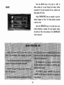
A WORD FROM CHEVROLET . ...
This Owners Guide contains important information regarding the operation and
maintenance of your Chevy II.
In order to obtain maximum enjoyment and usage from your car, we suggest that
you familiarize yourself with the contents of this booklet and follow the recommendations outlined.
Your Chevrolet dealer has the trained personnel and specialized equipment to
properly service your Chevy II. Have him inspect your car and perform any maintenance adjustments required.
We would like to take this opportunity to thank you for choosing a Chevrolet
product-and assure you af our continuing interest in your motoring pleasure and
satisfaction.
CHEVROLET MOTOR DIVISION
© General
MDtors CDrporation 1965
•
GENERAL MOTORS CORPORATION
DETROIT, MICHIGAN
41202
SECOND EDITlON
OCT08fR, 19 65
Page
Operating Instructions ....••...• : ..
3 thru 7
8 and 9
Instruments .. _....... ...•. _... . . . .
Controls . .... . . -.. . . . . . . . . . . •.. . 10thru 17
Other Features .................. 1 8 thru 21
Station Wagon ..... . •........... 22 and 23
Cleaning Your Chevrolet. ................. 24
Ma_in,tena 'nce and Lubrication .. . . . . . . 25 thru 36
Minor Trouble Shoating .. . . ....•. .. 37 thru 40
Specifications ...... ... . . ...... .. 41 thru 43
Index ............................... 44
All in'formation contained in this booklet is the latest product 'information available at th. lime of printing. The right
is reserved to make changes at any tim e without notice.
2
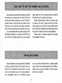
Sound design and precIsion manufa-during methods
'will permit you to operate your new Chevy IT from its
very first mile without adhering-' to - 0 formal "breok~jn"
schedule . However, during .he first few hundred miles of
driving you can, by- observing a few simple ,precautions,
add to the future performarice and economy of your car.
It is recommended that your speed during the flrst
500 miles be confined to a maximum of 60 M.P.H., but
do not drive for e'x tended periods at anyone constant
speed, either fast or slow. During this period, avoid full
throttle starts and, if possible, abrupt stops.
Gentle braking during the first few hundred miles
of operation will result in longer brake life and better
future performance. Avoid hard stops especially during
the first 200-miles of operation since 'brake misuse during
this period will destroy much futur'e brake efficiency.
Always drive at a moderate spe,e d until the engine
has completely warmed up.
Proper maintenance and wise operation will combine
to help you achieve maximum fuel economy with your
Chevy II. Your Authorized Chevrolet Dealer can properly tune and maintain your car but wise operation is
your responsibility. Give the car sufficient warm~up
time, do not moke full throttle starts or needless sudden
stops, and drive -at reasonable speeds and as steadily as
traffic permits to gain the benefits of all the economy
built into your Chevy II.
3
OPERATING INSTRUCTIONS
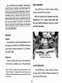
STARTING THE ENGINE
SWITCH OFF
AND LOCKED
ACCESSORY
DRIVING
POSmON
/
ON
START
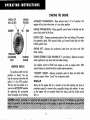
AUTOMATIC TRANSMISSION - Place selector lever in N or P position. The
engine will not sta rt when lever is in any other position.
MANUAL TRANSMISSION - Place gearshift conlrol lever in Neutral and depress dutch pedal to the floor.
ENGINE COLD - Depress accelerator pedal to floor and release. This presets
the automatic choke . With manual choke, pull control knob fully out while
holding pedal down.
ENGINE HOT - Depress the accelerator pedal part way down and hold
while starting.
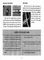
ACCESSORIES
ONLY
STARTING
ENGINE
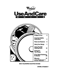
IGNITION SWITCH
The ignition switch has four
positions as shown. The key
may be removed only when the
switch is in the OFF position.
The ' key must be pushed in as
you lurn to ACCESSORY position
for operating the accessories
when the engine is not running.
DURING EXTREMELY COLD WEATHER (0 ' F. and belowl- Depress the accelerator pedal part way down and hold while starting.
Turn ignition switch to START and release as soon as engine starts . With
manual choke, set control knob for smooth engine operation.
"FLOODED" ENGINE - Depress accelerator pedal to floor and hold while
cranking engine. Never "pump" the accelerator pedal.
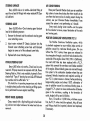
WARM-UP
Always let the engine idle for a moment or two after starting and drive at
moderate speeds for several miles, especially during cold weather. As soon
as the engine will run smoothly without the choke, push the choke control
fully in.
4
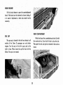
consumption. Use the choke, as outlined under "Startin9," only until the engine warms -up. Then if the choke
is still necessary to provide smooth engine operation
your Chevrolet dealer should be called upon to perform
such engine adiustments as may be necessary.
MANUAL CHOKE
The Chevy II with the Super-Thrift 4-cylinder engine
is equipped with a manual choke. Since the choke oper-
ates to enrich the fuel mixture delivered to the corbu.
retor, its improper use can result in excessive fuel
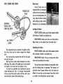
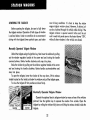
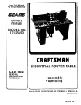
DRIVING WITH THE CHEVY II MANUAL TRANSMISSIONS
The 3-speed manual transmission shift positions follow the standard
pattern shown at the left. The 4-speed transmission shift lever, extending from the floor, has its special shift pattern diagram located on the
floor plate. Depress the clutch pedal fully before attempting to shift
to a different gear, then release the pedal to move in that gear. Shifting into 2nd and 3rd gear as soon as possible will add appreciably
to your fuel economy. Always shift into a lower gear, when slowing
down, before the car begins to "lug" or labor and also when descending steep hills. Both transmissions, being fully synchronized, may be
downshifted into lst gear at any speed below 20 m.p.h. Shift into
Reverse gear only after the car has stopped. Always depress and
release the clutch pedol fully when shifting.
When a push start is necessary turn off all electrical loads such as
heater, radio, and, if possible, lights, turn on the key, depress the
clutch, and place the shift lever in 3rd gear. Release the clutch when
your speed reaches 10 to 15 miles per hour. Extra effort will be required to operate power steering and power brakes until the engine
starts.
FOUR SPEED TRANSMISSION REVERSE SHIFT - Lift up on the reverse release cable handle just below the shift lever knob when shifting
into reverse gear. The shift linkage may be adjusted to allow "short
stroke" shift lever operation. See your Chevrolet Dealer.
5
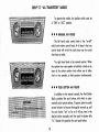
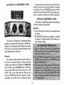
The Powerglide is a completely automatic transmission which replaces the standard clutch and transmission.
After starting the engine with the selector lever in N
(Neutral) or P (Park) position, select the range desired
(see tables below) and depress the accelerator. A gradual start with a steady increase in accelerator pressure
will result in greatest fuel economy. Rapid acceleration
for fast starts will result in greater fuel consumption.
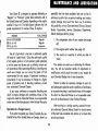
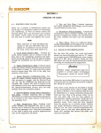
COLUMN SHIFT LEVER
The heavy line in the illustration below indicates
the movement of the shift lever as it is lifted to shift into
Reverse or Low and into or out of Park position.
FLOOR CONSOLE SHIFT LEVER
The floor console shift lever may be moved freely
between Neutral and Drive. Press lightly on the shift
lever button as you shift into Reverse or Low. Depress
the button fully when shifting into or out of Park position.
Exercise care in depressing the button to prevent unintentional shifts to Park or Reverse.
P-PARK
Use only when car is stopped.
R-REVERSE
For backing car-from stop.
N-NEUTRAL
For standing (Brakes Applied).
D-ORIVE
For forward driving. Depress accelerator to floor for extra
acceleration below 45 mph-:V-8, 40 mph-L-6.
L-LOW
For hard pulling through sand, snow or mud, and for climbing
or descending steep grades. Do not shift to Labove 40 mph.
6
HOLDING CAR ON AN UPGRADE
When stopped on an upgrade, maintain your position by applying the brakes. Never :hold 'he car in place
by acceleraling - engine . This co old- cause damage -by
overheating the-transmission .
"ROCKING" CAR
or
"Rock" the car to free it from mud, sand
snow by
accelerating the engine 'a s -r equired and moving the
transmission selector lever between 0 and R positions.
PUSHING TO START - POWERGLIDE
Turn off all eJectrical loads such as radio, heater
and, 'if possible, lights ,until the engine starts.
With the ignition key turned ON and 't he transmission in N (neutral). allow the car speed to reach 25 -to
30 miles per hour. Then shift the transmission to L (low)
position. After the engine starts, the transmission may
pe operated in - the normal manner. Never tow the caJ
to ,start. Extra effort will be required to operote the
power brakes and power steering until the engine starts.
of 3S miles per hour or less un'der most conditi'ons.
However, the drive shaft must be disconnected or
the car towed on its front wheels if 1) Tow speeds in
excess of 35 ·mph ·are necessary, 2) Car must be towed
for extended distances (over 50 milesl or, 3) Transmission is not operating properly. If car is towed on
its front wheels, the steering wheel should be secured
to maintain a straight ahead position.
PARKING YOUR CAR
TOWING
Always engage the parking bra.ke and place the
tran smission selector lever in " Park" position when
leaving your car unattended.
The car may be towed safely on its rear wheels with
the selector lever in " N" (Neutral) position at speeds
7
INSTRUMENTS
The instruments, gauges and indicator lights con·
veniently grouped in the instrument cluster are designed
stand and properly interpret these instruments. Familiar-
to tell you at a glance many important things about the
a practice to scan the instrument cluster as you start the
performance of your car. The information on this and
the following page will enable you to more quickly under.
engine, after it starts, and periodically as you drive.
HEADLIGHT BEAM INDICATOR LIGHT
are in use. The Headlight Beam Switch controls the headlight beams (see Page 11).
ize yourself with their location and purpose and make it
The headlights of your Chevy II have high and low
beams to provide you with proper night-time visibility
during all driving conditions. The " 'ow" beams are used
during most city driving . The "high" beams are especially
useful when driving on dark roads since they provide
excellent long range illumination. The headlight beam
indicator will be on whenever the high beams or "brights"
FUEL GAUGE
This electrically operated gauge registers correctly
when the ign ition switch is in the " on" position. When
the ignition switch is turned "off," the needle will not
necessarily return to the empty mark but may stop at any
point on the dial.
8
ENGINE TEMPERATURE INDICATOR LIGHT
some reason the engine reaches a dangerously high
operating temperature. If the red light should come on,
the engine must be stopped until the cause of the overheating is corrected.
Check this light frequently as you drive. Engine
temperature is normal as long as the red light is off.
An indicator light is provided in the instrument cluster
to indicate a normal operating engine temperature and
also quickly warn afan over·heated engine. As you
start the car, the red indicator light will go on to let
you know that it is operating properly.
After the engine starts, the red light will go out
immediately, It will light up at no other time unless for
OIL PRESSURE INDICATOR LIGHT
remains on during normal driving speeds the engine
should be stopped until the cause of the trouble can be
located and corrected. Driving the car with low oil
pressure can cause serious engine damage.
This light will be on when the ignition,. switch is
turned on and should go out after the engine is started.
Occasionally the light may be seen to flicker momen-
tarily, but this will do no harm. However, if the light
GENERATOR INDICATOR LIGHT
This light provides a quick check on the generating
system of your Chevy II. The red light will be on when
the ignition key is in the "on" position, but before the
engine is started. After the engine starts, the light should
go out and remain out. If the light remains on when
engine is running, have your Authorized Chevrolet Dealer
locate and correct the trouble as soon as possible.
9
CONTROLS
LIGHTER
MANUAL
CHOKE
(4 CYLINDER ENGINE)
RADIO
GLOVE BOX LOCK
HEATER
GLOVE BOX
LIGHT SWITCH
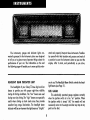
The three position light control switch con,trols the
headlights, taillights, parking lights. instrument lights
and dome lights os shown. The headlight and porkin~
light circuits are protected by a circuit breaker. in -the
light switch . An overload wnt cause the lights to "flicker"
on and off'. If this _condition exists, have your Chevrolet
Dealer check your -headlight and parking light wid-n g
immediately.
10
TURN SIGNAL
HEADLIGHT BEAM SWITCH
Move the lever up for a right tvrn and down to
indicate a left turn. The instrument panel indicators will
flash to indicate the direction of the turn being signaled.
When the turn is completed,
the lever will return to neutral. In the event of a very
"High" and "low" headlight beams are controlled
wide turn, it may . be
neces~
by the floor button at your left foot. The Headlight Qeom
sary to turn off the signal
Indicator, located in the instrument cluster, will show
"BRIGHT" when the high beams are in use. Always use
"low beam" when approaching or following other cars.
manually.
11
is required with r~gular brakes. A built-in vacuum reserve
BRAKES
will supply two or more power assisted brake
All Chevy II models are equipped with self-adjusting
brakes which eliminates periodic brake adjustments. The
self·adjusting mechanism is actuated, as needed, every
time the caf is moved in reverse .and the brakes applied .
It is possible, however, far excessive broke pedal travel
to develop if the required reverse movement with a
brake application does n-o t toke place during a pro·
longed period of stop and gO' forwcird driving . Should
thi s occur, the car 'should be driven backward and forward with ,the brakes applied at the end of each directional movement, until the brake pedal travel is bock
to normal. If ·this procedure fails to restore normal pedal
Ira,vel, ar if any abnormally rapidincrea,s e in 'ped'a)
travel is experi'enced, immediate inspection should be
made by your Authorized Chevrolet Dealer. Cdre, should
be exercised to as sure that full broke pedal -travel cannot
be obstructed by improper floo-r mats or other interfering
material under the pedal.
applica~
tions after the engine has stopped. After ,this, additional
foot pressure will be needed for brake respa:,ise.
Parking Brake
The hand operated parking brake is conveniently
located iust to the right of the steering column.
•
Pull the cane type handle toward you to apply the
parking brake. This mechanically sets the rear wheel
brakes. The handle will, remain in the extended position while the parking brakes are appHed.
•
To release the parking brake, turn the handle clockwise and allow it to return to its original position.
METALLIC BRAKE LININGS
Vehicles equipped with optional metallic brake linings, whether with standard or power brakes, will require
somewhat more relative pedal pressure when cold than
conventional brake-linings. This condition will exist only
until the unifs warm -up, several stops at most.
Power Brakes
Cars equipped with power brakes utilize engine
vacuum to re duce the brak ing effort to' much less than
12
G. M. Windshield Washer Solvent and Anti-freeze added
to the water aids in cutting road fUm and grease from
the windshield, and prevents freezing in the winter.
CLUTCH ADJUSTMENT
Clutch adjustment should be checked and adjusted
periodically as necessary to compensate for clutch facing
wear . To check, depress pedal by hand until resistance
is felt. Free travel of pedal should be approximately %.
inch; if very Httleor no free travel is evident, clutch adiustment is required.
Solvent should be used according to the directions
on the bottle. Be certain to use the correct concentration
during freezing weather.
Fill the washer jar only % full during the winter to
allow for expansion if the temperature shoold fall low
enough to freeze the solution.
WINDSHIELD WIPER AND WASHER
Turn the control knob clockwi'se to start electric
windshield wiper. The two~speed electric,wiper has both
a "low" and a "high" speed position.
The washer operating button is located in the center
of the wiper control knob. Pressing the button will send a
measured amount'of water or other cleaning agent onto
the windshield and will also cause the wiper knob to
turn, thus starting the wiper motor. The wiper will then
continue to operate until manually turned off at the
wiper knob.
Keep the water container under the hood filled at
all times. Avoid operating the washer when jar is empty.
13
KEYS, DOORS AND LOCKS
Door Locks
Chevy II door locks are
designed both for passenger
safety and for the security of
your car and possessions. Always keep the doors locked
when driving as well as when
IGNITION,
DOOR LOCK
AND TAIL GATE
leaving the car unattended.
Locking the Door.
FRONT DOORS, Inside-push inside release handles
Outside-use ignition key.
fully forward.
REAR DOORS, Inside-push down on locking button.
(Rear doors can be locked from the inside only.)
ALL
LOCKS
Unlocking the Doors
The octagonal-end key operates the ignition switch,
front door locks and (on station wagons) the tailgate
FRONT DOORS, Inside-pull inside release handles
Outside-use ignition key.
fully rearward.
lock.
The round-end key operates the locks for the glove
REAR DOORS, Inside-lift up on locking button. (Rear
box and the trunk.
doors must be unlocked from inside.)
Each key has a serial number stamped on a removable plug. This number will enable you to have another
key made in the event that the. original is lost.
To avoid the possibility that unauthorized persons
might duplicate your key, it is strongly recommended
that you record the serial number and then, with a ham-
Before the rear door can be opened from either inside
mer and punch; remove the knockout plug.
or outside, the locking button must be raised.
The rear door release handles are inoperative whenever the locking button is depressed. This feature is of
particular value if young children ride in the back seat.
14
CHEVY
n
"ALL TRANSISTOR" RADIOS
To operate the radios, the ignition switch must be
in "ON" or "ACe" position.
•
•
•
MANUAL AM RADIO
The Jeft hand radio control knob is the. "on~ofl"
switch and volume control knob. At its base is the tone
control knob with which the radio. tone may be varied
from bass to treble.
The right hand knob is the manual selector. When
the optional rear seat speaker is installed, a knob at the
base of the station seledor knob allows use of either
front or rear speaker, or both speakers simultaneously.
•
•
•
PUSH BUTTON AM RADIO
In addition to the manual controls, the Push Button
Radio provides five push buttons with which to auto~
maticallyselect preset stations. To preset, allow the radio
several minutes to become thoroughly warmed up, pull
the push button "out" as far as it will go/tune in the
desired station manually and then push the button fully
"in." Repeat this operation for each push button.
15
Push the AIR-FAN lever to the right to "AIR" to
allow outside air to pass through ~he heater. Further
movement of the lever operates the low, medium and
HEATER
high speeds of the fan_
Adjust TEMPERATURE lever as required to give the
desired degree of heat. Full right position provides
maximum heat.
Move the DEFROSTER lever to the right when windshield defrosting is needed. Full rig~t position diverts
the entire air flow to the defroster. Vary TEMPERATURE
lever as required.
16
ALL-WEATHER AIR CONDITIONING SYSTEM
During periods of less severe heat and humidity the
AIR lever may be set to the right to blend in a portion
of outside air. Vary the TEMP-COOL knob and the FAN
switch (which must be turned "ON" during cooling operations) as necessary to satisfy your comfort requirements.
CUSTOM AIR CONDITIONING SYSTEM
The Custom Air Conditioning System will provide you
with warm weather driving comfort.
Operation
• Turn the FAN knob to control the three-speed blower
as desired .
• The TEMP-COOL knob may be regulated to provide
the degree of cooling desired. Fully clockwise provides maximum cooling.
The Chevy II All Weather Air Conditioning System
operates in conjunction with the heater to provide conditioned air for passenger comfort during every season
of the year. Air flow may be directed through two side
louver outlets and four ball outlets.
Operation
For maximum cooling capacity when first turning on
the system and during periods of extreme heat and
humidity, set the AIR lever to INSIDE, the TEMPERATURE
lever to COLD, and the DEFROSTER lever to OFF. Push
the three speed FAN switch fully down, pull the "AIR
(OND" knob on the under dash unit fully out, and
rotate the TEMP-COOL knob fully clockwise. Cooled,
recirculated air will flow from the adiustable outlets.
17
OTHER FEATURES
ASH TRAY
AIR VENTS
The air- vents ineQch kick panel admit air from the
Pull on the lower edge of the ashtray to open . To
vent' grille,iust. anead of .the windshield. Control knobs
shown below Qpen and close the _ventS .
remove th.e tray, pull fully out, dep.ress, and then fernOV,e .
To install, insert tray in opening arid push back into place.
FRONT. SEAT ADJUSTMENT
The front seat may be quickly and easily adiusted
forward or rearward to provide maximum driving com·
fort. (Your Authorized Chevrolet Dealer can makeadditional adjustments to further tailor the seat to your
particular comfort requirements. When the additional adiustment is made rearward on a station wagon, the front
seat back maybe damaged if ·the second seat is folded
with the front seat in its rear position .)
CLOCK
Re set the clock, if your caf is so equipped, by pulling
out the knob and turning the hands clockwise if slow,
counterclo-ckwise jf fast. This will, if the clock error is
Pull back the seat adiuster lever, located on outboard
side of the front seat, to unlock the seat and allow adiustment to the front o~ rear. As the seat slides forward, it tilts slightly to provide best posture and increased
driving ease. Release the lever to lock the seat in the
desired position.
three minutes or more, automatically compensate for
time gain or lag . Several' resettings, several days apart,
may be needed to properly adjust the clock mechanism.
Have your clock cleaned _and oiled by a competent clock
serviceman at lea st every ·two years.
18
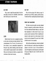
POSITRACTION REAR AXLE
sag or bumps. Air is added to the rear shocks as needed
through the air valve located along side the gas filler
neck.
The optional Positraction rear axle will give you
constant driving force on both rear wheels, especially
helpful in the winter and during other slippery driving
conditions which might stop a conventionally equipped
vehicle. During turns, the positractionaxle applies the
maior driving force to the inside rear wheel thus improving stability and cornering. Normal light throttle
application will supply maximum traction. When starting
with one rear wheelan an excessively slippery surface,
slight application of the parking brake may be neces-
A minimum pressure of 10-15 psi. should be maintained at all times. After the car is loaded, pressure may
be increased until the rear of the vehicle reaches the
desired riding height or to 0 maximum of 90 psi.
GLOVE BOX
The glove box is locked and unlocked with the round
key.
sary momentarily to gain maximum traction.
POWER STEERING
SUPERLIFT AIR ADJUSTABLE SHOCK ABSORBERS
Optional Superlift air adjustable shock
The optional Chevy II Power Steering system supplies about 80 % of the effort needed to turn the front
wheels. Should the engine stop, your Chevy II may still
be steered safely, but with somewhat greater effort.
abso'r~ers
allow you to ride with the trunk or load space of your
car or station wagon fully loaded but with no annoying
19
HOOD RELEASE
Pull the hood release to open the counterbalQnced
hood. If the hood must be slammed- to )nsure dosing, it
is in need of adjustment. A hard slam should not be
necessary.
REAR COMPARTMENT
GAS CAP
Unlock and open the counterbalanced trunk lid with
The ,gas cap is lo'c ated in the left rear fender in all
the round-end key. Close the, lid firmly to dose the lock.
The spare tire and auto jack are located in ' the trunk as
shown.
models 'o'f the ,Chevy II passenger cars and station
w'a gons. Turn the cap to the left to open and to, the
right to close. When closed the cap fits flush with the
fender. The cap is not vented.
20
CHEVY II SEAT BELTS
Fasten your seat belt by pushing the metal catch into
the buckle until it "snaps" into place. Tighten the belt
until comfortably snug by pulling on the loose end extendingfrom the buckle. Do not wear the belt loosely. Loosen
by turning the entire buckle outward. Lift up the buckle
lever to unlatch and release the belt. Never buckle an
individual seathelt around more than one person.
REGULAR EQUIPMENT BELT
It is recommended that seat belt retractors be used
on the outboard belt half only. When buckling the belt be
sure it is fully extended so there is no webbing wound
PULL TO
PRESS HERE TO RELEASE
around the retractor drum, then adiust for proper· fit at
the buckle.
Clean belts when necessary, without removing from
the car, with a stiff bristle brush using a detergent recommended for nylon. Never bleach or
OPTIONAL BELT
dye seat belts.
21
STATION WAGONS
LOWERING THE TAILGATE
most driving conditions it is best to keep the station
wagon tailgate window closed. However, if de sired, air
can be circulated through the vehicle while driving if the
tailgate window is opened several inches and the air
Before opening the tailgate, be ,sure to fully lower
the tailgate window. Operation of both types of window
is outlined below. Under no condition do we recommend
vent in each kick panel open o r the heater blower "ON",
d riving with the tailgate (loWer portion) open, and under
while all other windows in the vehicle are do sed.
Manually Operated Tailgate Window
Unlock the tailgate using the ignition keYI then lower the window by pulling
out the window regulator handle at the arrow end and turning the handle
countercbckwise. Rotate handle clockwise and snap into place.
Raise the window by pulling out the window regulator handle at the arrow
end and turning the hand le clockwise. Rota te handle counterclockwise and
snap into place .
To open the tailgate, lower the window all the way down, lift the release
handle located on the in side iust below the window and pull the tailgate open.
To close the tailgate lift into position and slam firmly.
Electrically Operated Tailgate Window
Operate the optional electric tailgate window by means of one of the switches
pictured . Use the ignition key to operate the window from outside . Open the
tailgate by rolling the window fully down and lifting the release handle inside the
tailgate.
22
STATION WAGON SPARE TIRE AND
JACK STORAGE
The spare tire and jacking equipment are stowed
behind in the right rear quarter panel. The tire is covered
by a plastic boot. The boot should be removed and in-
stalled while the wheel and tire are out of the vehicle.
A movable flap allows access to the large wing nut
which secures the tire and jacking equipment. Be sure
the .jacking equipment is. properly installed before the
tire is set into place to avoid annoying rattles.
I
OPERATING THE FOLDING SEATS
Thereaf seat of your Station Wagon may be quickly
and easily converted into cargo space when needed.
•
Release the locking lever on the right hand side of
the rear seatback.
•
Pull seatback forward and down.
•
To raise theseot,lecin on the front edge of the seatback panel to remove tension from the filler panel,
lift up the filler panel at the location shown above,
then lift seat back up and rearward until it locks
into place.
•
z-::
WAGON
Operate both sections of the optional two-section
second seat in the same manner.
23
CLEANING YOUR CHEVY II
required. However, G. M. Chrome Polish may be used
on CHROME or STAINLESS STEEL trim if necessary. Use
special care with ALUMINUM trim. Never use auto or
chrome polish, steam or any caustic soap to clean
aluminum.
A coating of wax, rubbed to a high polish, is recommended for all bright metal parts.
EXTERIOR APPEARANCE
Your Chevy II is finished with General Motors
"Magic-Mirror" acrylic lacquer. This is a finish of maximum beauty which, in depth of color, gloss retention and
durability is superior to conventional lacquer finishes.
Washing Your Chevy II
The best way to preserve. the finish and maintain
original beauty of appearance is to keep it clean. Wash
the car in lukewarm or cold water. Never use strong soap
or chemical detergents. Cleaning agents should be
quickly flushed from the surfaces.
Use a tire cleaner which will not harm aluminum trim.
A stiff brush may be used with the cleaner to remove road
grime and dirt from white sidewall tires.
Polishing and Waxing Your Chevy II
INTERIOR APPEARANCE
Although acrylic paint on your car is durable, you
may wish to wax or polish for added protection. Your
•
Use Leather Cleaner to clean imitation leather, vinyl
or coated trim fabric on seats or door panels.
•
•
Kar Kleen Upholstery Cleaner will remove most stains.
Use of a volatile cleaner is recommended for oil,
grease, and road grime stains.
•
Polish should not be used to clean interior bright finish
parts. Abrasive compounds used in most polishes may
damage the finish. Cleaning with a damp cloth, then
rubbing with a polishing cloth is all that is required.
•
Use soap and other solutions with caution.
Cleaning White Sidewall Tires
Chevrolet Dealer offers many polishes and waxes now
available which have proven of real value in maintaining
a good paint finish. When using a tar and road oil remover, be certain it is safe for use on acrylic painted
surfaces.
Protection of Exterior Bright Metal Parts
Bright metal parts should be cleaned regularly to
maintain luster. Washing with water is all that is usually
24
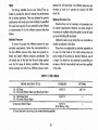
MAINTENANCE AND LUBRICATION
Your Chevy II is designed to operate efficiently on
"Regular" or "Premium" grade fuels commonly sold in
the United States and Canada, depending on the engine
installed in your car. The toble below indicates the fuel
grade requirements for vorious Chevy II engines.
ENGINE
All 4 & 6 CYLINDER
283 Cu. In V~8
327 Cu. In. V-8
possibility that the best available fuels are so low in
anti-knock quality that excessive knocking and serious
engine damage may result from their use. To minimize
this possibility, write to Chevrolet Motor Division, General
Motors Corporation, Service Operations Department,
Detroit, Michigan 48202, giving:
FUEL GRADE
1. The compression ratio of your engine (see page
Regular
Regular
Premium
42)
2. The engine serial number (see page 41)
Use of a fuel which is too low in anti~knock quality
will result in "spark knock." Since the anti~knock quality
of all regular grade or of all premium grade gasolines
is not the same and factors such as altitude, terrain and
air temperature affect operating efficiency, knocking may
result even though you are using the grade of fuel
recommended for your engine. If persistent knocking is
encountered, it may be necessary to change to a higher
grade of gasoline and, if knocking continues, consult
your authorized Chevrolet Dealer.
In any case, continuous or excessive knocking may
result in engine damage and constitutes misuse of the
engine for which the Chevrolet Division is not responsible
under terms of the Manufacturer's New Vehicle Warranty.
3. The country or countries in which you plan to
travel.
Your dealer can assist you in obtaining this information. You will be furnished details of -adjustments or
modifications which should be made to your engine by
your Chevrolet Dealer prior to your departure.
Failure to make the necessary changes to your car
and subsequent operation under conditions of continuous
or excessive knocking is considered misuse of the engine
for which the Chevrolet Division is not responsible under
terms of the Manufacturer's New Vehicle Warranty.
After arriving in a foreign country, contact the nearest authorized General Motors Dealer for brand names
of the best fuels available and advice as to where they
may be purchased.
Operation in a Foreign Country
If you plan to operate your Chevy II outside the continental limits of the United States or Canada, there is a
25
regularly. Keep oil level between the FULL and ADD
marks, by adding oil when level is at or below the ADD
mark. It is not necessary to keep the level at the FULL
mark. DO NOT OVERFILL.
OIL VISCOSITY AND QUALITY
The use of high quality oil of the correct viscosity is
your best assurancebf continued reliability and· performance from your engine.
It is recommended that you use an oil which, accord-
AIR INJECTION REACTOR (A.I.R.I
ingto the label on the can is:
(1) infendedfor service MSand
(2) passes car makers'tests or meets General Motors
Standard GM 4745-M.
Oils conforming to these types contain detergent
additives.
(C~lifornia
The Air Injection Reactor System is standard equip:ment on most 1966 GM cars and trucks delivered in
California. This new air pollution control system is entirely
separate. from the· Positive Crankcase Ventilation System
and is designed to reduce air pollution caused by engine
exhaust tailpipe gases by "treating" the unburned hydro~
carbons and carbon monoxide as they are expelled from
the combustion chamber into the exhaust manifold. A
sealed bearing pump, driven by the engine, compresses,
distributes and iniects clean filtered air at the exhaust
port of each cylinder. Here it combines with the un~
burned hydrocarbons and carbon monoxide at high tem~
peratures in a chemical reaction, producing a "treated"
exhaust that is below the maximum allowable level for
air pollution from this source. This does not reduce the
danger of inhaling any concentration of carbon mon~
oxide in a confined area. See Page 4 for carbon mon~
oxide warning.
The Air Injection Reactor System requires no special
maintenance other than an annual belt inspection and
adiustment. The annual engine tune~up recomm'ended for
normal engine efficiency, operation, and performance is
important for the A.I.R. system's continued effectiveness.
Lowest Anticipated
Temperature .During
Time Oil Will be
inthe Crankcase
Viscosity
Oils
MultiVis<;osity
Oils
32° F.
SAE20or20W
SAE 10W-30
0' F.
SAE lOW
SAE 10W-30
Below 00 F.
SAE 5W
SAE
Single
Vehicles Only)
. - ~~-
5W-20
NOTE1: SAE 30 or 10W-30 is recommended when most of
the driving is at high speeds and/or at tempera-
tures above 90° F.
NOTE 2: SAE 5W-30 oils may be used during periods when
temperatures of 32° and below are to be expected.
OIL LEVEL
Regardless of the change interval being followed
check the oil level (with the engine hot) on the dipstick
26
• To remove the cap; turn a quarter of a turn to allow
the pressure in the cooling system to escape safely, then
turn the cap all the way off.
Your Chevy II engine cooling system is equipped
with a 180 0 thermostat (195 0 when Air Injection Reactor
System is installed) and is designed to operate on permanent type (ethylene glycol) anti-freeze. Non-Permanent
type coolants are not recommended since they are not
satisfactory for year around use and may not effectively
inhibit corrosion of the engine cooling system when used
with the quality of water found in some areas.
If the anti-freeze was installed at the factory or if it
meets the requirements of General Motors Standard GM
1899-M which contains adequate corrosion protection, it
may be left in the cooling system for 24 months or 24,000
miles, whichever occurs first.
Check the coolant level at each engine oil change.
Level should be 111 below top of filler neck when cold.
Add water or permanent anti-freeze as required to maintain proper level. Concentration of coolant should be to
0 F. or· below to insure sufficient corrosion protection.
Drain and flush cooling system every 24 months. Fill
with mixture of permanent type anti-freeze (GM 1899-M
or equivalent) and water to provide proper concentration
of coolant.
Each fall have your Chevrolet dealer inspect the cooling system to insure that all connections are leakproof
and anti-freeze content will provide adequate protection
in cold weather.
The radiator cap, a 15 lb. pressure type, must be
installed tightly.
CAUTION: After a long hard drive or after driving during
extremely hot weather, never attempt to remove the
radiator cap until the engine has been stopped and
allowed to cool for several minutes. Then carefully
remove the cap as described above.
To completely drain the cooling system:
Be sure to replace the drain plugs before refilling the
cooling system.
The cooling system should be flushed with plain
water after each coolant drain.
• All models-remove the radiator cap and the drain
plug at the bottom of the radiator.
• Six Cylinder engine-remove the drain plug located
at the left rear side of the block.
• Eight Cylinder engine - remove the drain plugs
located on each side of the v-a block just above the
oil pan.
0
BATTERY CARE
Check the fluid level in each cell of your battery
regularly. Keep filled with distilled water to the bottom
of the split ring in the vent tube. DO NOT OVERFILL.
27
mended for full rated load. Tire inflation pressures may
increase as much as 6 pounds per square inch (PSI)
when hot.
TIRES
The -f actory installed tires on your Chevy II are se;'
lected to provide the best all. around tire performance
for all normal operation. They _ore designed to operate
Optional Oversize Tires
Oversize tires are ·n ot necessary on passenger cars
for normal requirements. Howflver, an extra margin of
tire service is available when ,this option is used at 'l oads
up' to and including full rated load.
Optional oversize 4-ply rating tires are ava ilable on
models as indi.cated in the table.
These tires _o re applicable to extended operation at
or near full rated load or for -troiler -towing when an
extra margin of tire service is desired. However, use of
a larger tire should not be construed as p~rmitting an
increase in the full rated vehiCle load over thQt s,p edfied
in the table.
satisfactorily with loads up to and including the specified
full rated load capacity of your automobile when' inflated
as' recommended in the tire inflation pressure table that
folloW's.
Inflation Pressures
To ensure the proper tire inflation pressure for your
particular _requirements, follow fh-e recommendations_ in
the tire inflation pressure table. Keep tires properly inflated and check inflation pressures periodically, This
will ensure you of the best tire life and riding comfort
over the full range of driving conditions . When loads
above average are ' carri~d use inflation pressu,re recom:-
CHEVY U TIRE USAGE
ENGtNE AND BODY STYLE
STANDARD
OPTIONAL
L-4, All Styles
L-6, All exce pt Station Wagon and Nova Su per Sport
6.50 X 13
6.95 X 14
L-6, Nova Super S'p ort
V-S, All exce{)t Station Wagon
6.95 X 14
All engines,' Station Wagon
6.95 X 14
(8-Ply Rating, 4-Ply)
All tires 'listed are 4-ply rating , 2-ply unless otherwise specified.
28
r
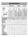
Vehicle Capacity Rating and Recommended Tire Inflation Pressure (PSI Tires Cool)
All Mode ls Except Those Shown Below
Tire inflation pressure (PSI)
Ply
Rating
4
1 to 5 Passengers
(750 1 Load)
6 Passengers + 2001 Trunk Load
(1100 1 Load)
Front
Rear
24
Ply
Rating
4
Front
24
Rear
24
Ply
Rating
Front
Rear
1. For continuous high speed operation increase tire pressures 4 pounds per square inch over the recommended
pressure up to a maximum of 32 pounds per square inch
cool for 4-ply rating tires or 40 pounds per square inch
cool for 8-ply rating tires.
Rear
32
Front
26
Rear
32
6 Passengers
3001 Cargo
(12001 Load)
,.-
..-
Front
+
1 to 5 Passengers
(750 1 Load)
-,-
..-
5 Passengers + 2001 Trunk Load
(950 1 Load)
1 to 5 Passenge,rs
(750 # Load)
Station Wagons
Tire inflation pressure (PSI)
Fu II Rated Load
24
"Bucket Seat" Mod e ls
Tire inflation pressure (PSI)
Average Load
Front
24
--..-
Rear
3. Cool tire inflation pressure: after vehicle has been inoperative for 3 hours or more, or driven less than 1 mile.
Hot tire inflation pressure: after vehicle has been
driven 10 miles or more at 60-70 miles per hour.
4. Station Wagon loads should be distributed as far forward
as possi ble.
5. Station Wagons with luggage racks do not have a vehicle
load limit greater than specified.
2. Over-inflation will adversely effect your tires, and the
durability and riding comfort of your car.
Under-inflation will promote heat and abnormal wear.
29
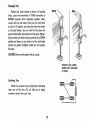
Changing Tires .
REAR
Position jack under bumper as shown . ' Set parking
broke, place the transmission in PARK (automatic) or
REVERSE (manual), block diagonally opposite wheel,
~
remove hub cap and loosen wheel nuts. Set small lever
on jack to UP position, and using the wheel nut wrench
as the jack handle, raise car until the tire clears the
ground. Remove the wheel and put on the spore, tighten~
ing the wheel nuts. Move the jack control lever to DOWN
position and lower car one notch at a time until wheel
touches the ground . Retighten whee1 nuts and replace
hub caps.
CAUTION: Never run the engine with car on jack.
POSITION JACK UNDER
BUMPER JUST OUTBOARD
OF BOLTS
_
Switching Tires
Rotate tires as shown every 6,000 miles to distribute
Wear over all five tires. This will help you to obtain
maximum service from your tires.
30
.-CI
I~!
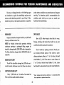
RECOMMENDED SCHEDULE FOR PERIODIC MAINTENANCE AND LUBRICATION
I
The time or mileage. intervals on the, following pages
are intended as a guide for establishing regular maintenance and lubrication periods for your Chevy II. Sustained heavy duty or high speed o_perotio"s or operation
under adverse conditions may necessitQ,te more fre,q uent
servicing. To determine specific recommendations for
conditions under which you use your car,consult your
Authorized Chevrolet Dealer.
I
DRIVE BELTS
ENGINE OIL'
Engine oil shouldbe changed at 60 day or 6,000 mile
Every 6,000 miles-Inspect drive belts for wear,
intervals, whichever occurs first.
fraying', cracking, and tension. Belts which are in poor
NOTE: For vehicles in heavy duty operation involving
continuous start-stop or prolonged idling; engine oil
~
condition should be ,replaced immediately.
should be changed alter 2500-3000 miles 01 operation.
The fllter should be changed alter 5000-6000 miles 01
operation.
sure midway between pulleys. If the center to center
ENGINE OIL FILTER'
should deflect % inch. If the center to center distance is
The oil filter should be changed at 6,000 miles or 6
month intervals, whichever occurs first. {See note above,'
7 to 1'0 inches, -the belt should deflect Y.. inch. loose
Check tension. by applying _modera.te thumb presdistance between pulleys is 13 to "6 inches, the 'be,lt
belts should be retensioned to: give the correct deflection.
VENTED OIL FILLER CAp.
Every 12,000 miles or 12 months-The vented oil
filler cop (where used) should be cleaned.
"Under prolonged dusty driving conditions, it is recommended that
these operations be performed more often.
31
FUEL FILTER
AIR CLEANER CARE'
Replace filter element located in carburetor inlet if
carburetor flooding occurs.
Paper Element Type-First 12,000 miles, inspect and
test element, if satisfactory, element may be reused but
must be rechecked every 6,000 miles thereafter. Element
must not be washed, oiled, tapped or cleaned with an air
hose.
Polyurethane Type-Every 12,000 miles clean element
in suitable solvent such as Kerosene, squeeze out all solvent, then soak in engine oil and squeeze out. Then
squeeze in a clean dry cloth to remove excess oil.
DISTRIBUTOR CAM LUBRICATOR
ENGINE TUNE-UP
4 & 6 Cylinder Engines-Rotate cam lubricator 180 at
12,000 mile intervals-Replace at 24,000 mile intervals.
0
Every 12,000 miles-Have engine tune-up operations performed to maintain maximum engine performance and fuel economy.
8 Cylinder Engine-Change cam lubricator end for end
at 12,000 mile intervals - Replace at 24,000 mile
intervals.
·Under prolonged dusty driving conditions. it is recommended that
these operations· be performed more often.
32
TRANSMISSION
BATTERY
Every 6,000 miles - Clean terminals and oil felt
3-Speed and 4-Speed
washer.
Every 6,000 miles-Check at operating temperature
and fill as necessary to level of filler plug hole with
SAE 80 or SAE 80-90 Multi-purpose Gear Lubricant meeting requirements of U.S. Ordnance Spec. MIL-L-2105-B.
BRAKES
Brake linings should be periodically inspected for
wear. The frequency of this inspection- depends upon
driving co nditions such as traffic or terrain, and also the
driving techniques of individual owners. Your Chevrolet
Powerglide
Every 6,000 miles-Check fluid level on dipstick with
engine idling, selector lever in neutral position, parking
brake set and transmission at operating temperature. If
fluid level is below full mark on dipstick, add small
amount of Automatic Transmission Fluid . Use either
General Motors Automatic Transmission Fluid (Part Num~
Dealer is best qualified to advise you as to how often
this inspection should be performed. When brakes re'qui.re relining use genuine General Motors Parts or
equivalent.
bers 1050012-3-4 available at your Chevrolet Dealer,
Supreme No. 11.
which has been especially formulated and tested for use
in your Automatic Transmission to provide maximum
trouble~free operation or other approved Automatic
Transm ission Fluid Type " A" identified by the mark AQ~
ATF followed by a number and the suffix letter " A".
Parking Brake Pulley, Cables and Linkage
Recheck fluid level on dipstick and ogain odd a small
amount of fluid if needed to bring level to full mark. DO
Master Cylinder
Every 6,000 miles-Check fluid level and maintain
% below filler opening with OM Hydraulic Brake Fluid,
II
NOT OVERFilL.
Every 6,000 miles-Apply water resistant EP Chassis
Lubricant to parking brake cable at cable guides and at
all operating links and levers.
Lubricate Powerglide shift linkage at frame and
mission with water resistant EP Chassis Lubricant.
33
trans~
· Every 12,000 miles (more frequently·, dep~nding on
FRONT SUSPENSION
severity of service, if vehicle is used to pull tra ilers, carry
Every 6,000 miles or 6 months-Lubricate .4 fittings
full loads- during high ambient temperatures, operate in
mountainous terrain or operate -under other severe
with water resistant EP Chass is lubricant.
-COIi-
Ball joints should not be lubricated unless their
temperature is 10°F. or higher. During colder weather, they should be allowed to warni up as nil'ce$:sary before lubrication.
ditions}-Remove fluid f~om the transm'i'ssion sump and
add one andon'e ,. half ,(1 %) quarts· of ,fresh fluid.
Operate transmission through all ranges ,and
ch~ck
fluid
level as -describeci above.
REAR AXLE
Standard
Every 6,000 miles:-Check and keep filled to level of
filler plug hole with SAE 80 or SAE 80-90Multi. Purpose
Gear Lubricant meeting requirements of U.S. Ordnance
Spec. Mll~l- 21 058.
PO$itraction
Same as standard axle but use only' the special positraction lubricant available from your Chevrolet' Dealer.
CLUTCH CROSS-SHAFJ
- El!-ce pt if vehide i~ e quipped with trans mi ssion provide d in heavy '
duty $ervice options . If so e quippe d, drain conve rte r and sump e very
12.000-miles and odd approximate ly seven-and one· half (7'12) quarfs
of fre sh fluid .
Every 36,.000 m,iles or sooner if necessa ry-Remove
the plug, install a lubrication fitting and lubricate with
water resistant EP Chassis Lube.
34
STEERING LINKAGE
AIR CONDITIONING
Every 6,000 miles or 6 months-lubricate fitting at
each tie rod end. (4 fittings) with water resistant EP Chassis lubricant.
Hove your Chevrolet Dealer check your air conditioning system at some time during the winter months to be
sure there has been no loss in cooling output. During the
summer, see your Chevrolet Dealer immediately if you
suspect the system is not performing as it should.
Every week-during winter months-run the system
for five minutes to insure proper lubrication of the seals
and moving parts.
STEERING GEAR
Every 36,000 miles-Check steering gear lubricant
level in the following manner:
1. Remove the forward and the outboard steering gear
POSITIVE CRANKCASE VENTILATION (P.C.V.!
cover attaching screws.
2 . Inject water resistant EP Chassis lubricant into the
forward cover attaching screw hole until lubricant
begins to come out of the outboard screw hole.
3 . Replace both cover attaching screws.
POWER STEERING PUMP
Every 6 1 000 miles or 6 months-Check level in pump
reservoir. Fill pump reservoir as required with G .M. Power
Steering Fluid or, if this is not available, Automatic Trans-
mission fluid "Type A " bearing the mark AQ-ATF followed
by a number and the suffix letter "A.It
Oil should be at operating temperature and wheels
in straight ahead position when checking or filling operation is performed to ensure against overfilling.
FRONT WHEEL BEARINGS
Clean, repack with a high melting point wheel bearing lubricant and adjust whenever the wheel and hub are
removed.
The Positive Crankcose Ventilation system, which
is standard equipment on your vehicle, helps control air
pollution caused by crankcase blowby gases. On cars
without the P.c. V. system, these gases are released to
the atmosphere through a road draft tube located on the
underside of the engine. Since 1963 (1961 in California),
the road draft tube has been replaced with a p.e.v.
system that connects the crankcase and intake manifold
of the engine. Exhaust blowby gases are returned through
this system to the combustion chamber where they are
reburned. Periodic inspection and required servicing of
your p.e.v. system assures a cleoner, beHer~performing,
longer-lasting engine and almost 100 % elimination of
any air pollution caused by crankcase blowby gases. A
plugged p.e.v. system can cause condensation of blowby
gases in the crankcase, resulting in the formation of
acids, sludge build-up and oil dilution.
Every 12 months or 12,000 miles, whichever occurs
. first, the P.c. V. valve should be replaced. Also, all hoses
and fittings should be inspected, cleaned and replaced,
if necessary.
35
Chevy II passenger cors are designed prhnarilyfor
conveyance. However,- it is well known that
many owners do use their Chevy II to pull traile rs, and
when available trailer hauHngoptions have been used,
tne owners nove experienced very sotisfactory service.
When a trailer is -attached to a car, th~ car becomes
not only a load-carrying vehicle, but a load-pulling
vehicle. The demands of this type of operation are very
different from those for which the automobile is primarily designed and may present problems, such as
spring and tire loading" braking t cooling, lighting, and
steering. Ho"-:t'ever, careful driving practices and the use
of factory-recommended options will better satisfy the
requirements of trailer- hauling.
If in the opinion of the manufacturer a part or component of a motor vehicle has been adversely affected
by misuse ,of the vehicle with trailer loads, such part, or
component will not be covered by the manufacturer's
warranty,
The size of and, equipment for trailers, including
such items as hitches and safety chains, brakes, lights,
power-weighfra,ios and over-all length, ore generally
subject to safety regulations in all states, and it is the
responsibility of the user to make certain thot he is in full
compliance with the regulations of the states in which
he plans to operate with a tr.ailer and of the_Interstate
Commerce Commission, if applicable l before doing so.
Further, when operating a car with a trai'lerattached,
the driver must realize thot the performance, steering
characteristics, and braking distance of his car have
been altered, and that he mud exercise greater caution
to safely handle -his cor and trailer.
p~ $ $eng~r
36
FUEL SYSTEM AND ENGINE
ELECTRICAL SYSTEM
If your car acts
in the 'ouowing
manner:
~-'---~
Check here in sequence
stlown ,. possible-causes.
37
CODLING SYSTEM
you may check further to see whether the fuel is reaching the'
carburetor. Disconnect the fuel 'line at the carburetor and remove
the center wire from the coil tower. Place a jar or cup under the
open line and briefly "c ronk" the engine by means of the starter.
If fuel spurts from the fitting, you may assume that the FUEL LINES
are clear and the FUEL PUMP is operating properly. If no fuel leaves
the line, either the fuel lines or
fuel pump are et fault. See your
Authorized Chevrolet Dealer.
MIN.OR TROUBLE SHOOTING PROCEDURES
The chart on the previous page, and the information on the pages
which follow, contoins informqJion designed to aid the averoge
driver to discover, and possibly correct, conditions resulting in minor
mechanical difficulties in his cor. The chart, designed to point out
possible solutions to severol of the_most common automotive mol·
fundio"s and point out (I logical checking sequence, will lead step
by step to the most likely causes and corrective procedures. If, after
making the checks and adjustments suggested, the source of the
trouble has not been found and corrected, it is strongly recommended that an Authorized Chevrolet Dealer inspect the vehicle and
make whatever repairs or adiustments are necessary.
(C) Before reconnecting the fuel
line to the carburetor, remove the
FUEl FILTER from the carburetor
inlet and check its condition. If it
appears to be dean, replace it
and reconnect the fuel line. If
the fllter appears to be plugged,
clean it as well as possible by
scraping out the foreign material
and cleaning in a solvent. Then
reinstall the fllter. Replace the
filter with a new one as soon as possible.
FUEL SYSTEM AND ENGINE
If the ignition switch will couse the engine to "turn over" or
"cronk" but the cor will not start, check Steps A through D below.
NOTE: If Continuol "flooding" of the carburetor is evidenced by a
carburetor wet with fuel or black exhaust smoke, perform the
operation suggested in paragraphD only.
(A) The first and most obvious,
and one of the most frequently
overlooked, items to check when
you have difficulty in sterting your
car is the amount of fuel in the
tank. Make it a hobit to check the
FUEL GAUGE regularly and most
especially at a time when the engine will " turn over" but will not
start .
Fuel Filte,
(O) If the fuel seems to be reaching the carburetor properly, the
problem may be: an EMPTY CARBURETOR Bowl caused by a "stuck
Shut" carburetor; a FLOODED CARBURETOR caused by a "stuck
open" condition and evidenced by gasoline flowing down the
outside of the carburetor; or a stuck CHOKE valve. Remove the
air cleaner from the carburetor. Check that the choke valve moves
freely and is not stuck. (Don't mistake normal spring tension for a
stuck valve.) Tap the side of the carburetor sharply several times
with a light tool such as a screwdriver handle or pliers. Replace the
air cleaner and attempt to start the engine in the normal manner.
(8) If the fuel tank is not empty,
38
POOR· BATTERY CONNECTIONS may be _suspected if the car has '
operated proper/yo short time before and now not even the horn
will operQte. Check ,both ends o(b'oth battery cables. If.,the' con·
nections ' are corroded, 'a car may sometimes be restored to oper~tion by remov_
ing all coble ends, scraping 011 contacting surfaces
clean with a pen knife, and --reassembling. If the cables are broke_n, ·
they must be replac~d. The power supply should now be restored
unlessth~,' battery is dead.
(E) If the car will start but -stalls when hot or has a rough id_le,
you can , suspect Q.· faulty IDLE ADJUSTMENT, a malfunctioning
AUTOMATIC CHOKE
0'
an ext,.mely di,tr and blocked AIR
CLEANER ELEMENT. Clean your air cleaner element if necessary.
Idle adjustment ' of 9utomatiC-choke service lother tht;m that outlined
in -paragraph n)should be performed by yo~r Chevrolet Dealer.
•
!
Hthe 'ab'ove Fuel ' System cheCks' cnd the ch.'e,ck,s suggesfed ,' under
the Electrical System f~lIowrhg do not correct the malfunction, it is
recommended that you turn to your Authorize:d Chevrolet Dealer
for further checks, adjustme.nh or repairs.
(H) _If, however, -the ligh'ts and horn work prope rly but the starter
wilLstili not turn- _over, check _the STARTER connections. A "dick"
from the starter solenoid indicates that the wiring to the: starter is
properly installed. If the wir"ing seems to be"dean and tightly in·
stalled, the trouble 'is probably in the starter itself (:IOd should be
referred to your Authorized Chevrolet Deal~r .
When the engine will " turn over" but will not start, the following
items may be checked along -with the -Fuel SysJem Checks listed
previously.
ELE.CTRICAL SYSTEM
If, whe'n the . ignition key. is turned to "Start', " the engine will not
turn. over, you have good reason to suspect electrical trouble .
NOTE: Never remove delcotron BAT lead without first disconnect·
ing, .battery ground cable.
(I) With a
plugs dry.
the cause
ally when
IF) When 't here is no response at all to atfempfsto start the car,
check the obvious-you, AUTOMATIC TRANSMISSION SElECTOR
lEVER must be_- in Neutral or Park position before the engine can be '
started. Turning the IGNITION SWITCH rapidly back and forth
several ,times will sometimes correct a poor internal switch contact.
(G) The BATTERY may be discharged. If so, lights will be dim and
the horn will hove a 'poor rone if it will blow at all.
,
clean dry doth wipe the ceramic portions of the spark
In particularly damp or rainy weather dampness may be
of not -sfarting, especi·
the engine; is cold.
(J) Check · the cables ot the top
of the distributor and coil as well
as each sP!ltk -plug coble for
tightness.
Usually a garage recharge will be necessary to return the
!lottery to operation. Oc;:casionally, however, a ,push start and long
drivewill recharge the battery.
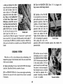
(KJ Ifth~ ' car will still not start,
check for spa;k at the spark plugs
in the following manner:
NOTE: 11 the battery is determined to be-dead, .and for no apparent
reason, have your Authorized Chevrofet Dealer check the
Pull one 'of the 'sPQrk plug
wires off its spark plug. Insert a
short piece of bore wire (such as
BATTERY, the GENERATOR ond the VOLTAGE REGULATOR.
GENERATOR trouble should already hav,"been indicated by
the generator indicator fight on the instrument panel.
39
Diirrihufor anti Coil CaI:J.s
(N) Check the RADIATOR CORE. Clean it if it is plugged with
bugs, leaves or other foreign material.
a bobby pin) between the rubber
cup ot the end of the spark plug
wire ond the tubular metal connector inside of it. If the spark
plug wire is wet or oily, wipe it
dry. Wrap a dry handkerchief
or facial tissue, folded several
thicknesses, around the wire at
least three Inches back from the
end and grasp the wire at this
point. Hold the bare wire about
% inch from the bore tip of the
Chec:kiftg Spark
spork plug from which you removed the wire. When the engine is "turned over" 0 spark should
jump across the % inch space, indicoting omple current supply. If
no spark jumps, the diffi culty is probably caused by a defective ignition part and should be corrected by your Authorized Chevrolet
Dealer.
(0) Condition of the FAN BElT
is very importont, not only for engine cooling but. also for proper
generator .operation. Check the
condition of the .belt. Replace it
if it is worn or frayed. loosen the
generator bo lts and move the
generator toward the engine to
remove and replace the belt.
Tighten the belt,· whether new or
old, by loosening the generator
Fern S.1t T.nsion
bolts, prying with a bar on the
generator until the belt is tensioned properly, then retighten the
generator bolts.
COOLING SYSTEM
(P) Another cause of engine
overheating may be an inoperative COOLING SYSTEM THERMOSTAT.lf the th.e rmostat should foil
in the dosed position, it will not
permit coolant to circulate through
the system. In such an emergency
the thermostat may be removed
but should be replaced with a
properly functioning thermostat
as soon as possible.
When the co r will run but evidences serious overheating on the
temperature gauge in the instrunient panel, there are several items
which may be checked.
(LJ Engine overheating will occur when the OIL LEVEL falls danger.
ously low. Check the oil level os a matter of course.
(MJ low COOLANT lEVEL will, of course couse engine overheoting.
Determine the cause of the low coolant level and have it corrected
if necessa ry.
40
Thermostat Installation
SPECIFICATIONS
SERIAL AND UNIT NUMBERS
CAPACITIES
Gasoline Tank
Car-Stamped on Vehicle Identification Plate attached to left
front body pillar.
.. Approx.
16 g~1.
Cronkcose (Refill)
4 Cylinder (with oil filter chongeJ-l pt. filter
4 qts.
6 and 8 Cylinder (with oil Alter change1 qt. filter .
. ........ .. . .
S qts.
All Models ...
Bod y -Stamped on plate attached to cowl panel.
I
Engine...:...5tomped on boss on block.
6·Cylinder-On right sid e of block to rear of distributor.
Cooling System . . 153 L-4
4-Cylinder-On right side of block to rear of distributor.
9 qts.
S-Cylinder-On right side of block at front.
•
283 V-8
327 V-8
11 qts.
17qts.'"
Th e rmostat .. 180 0 (195 ° when Air Injection Reactor System
is installed ).
RCldiator Pressure Cap .
15 lb.
"with air condo odd 1 qt.
• "with air condo add 2 qts.
DIMENSIONS
Overall length . .
194 L-6
230 L-6
183"
BATTERY RATING
Height . ...... ...... .
55.1"
Width.
71.3"
L4, l6, and 283 V8 engine e quipped vehicles-12 volt" 54
plate, 44 amp/hr.
110.0"
327 V8 engine equipped vehicles-12 volt, 66 plate, 61
Clmp/ hr.
Wheelbase .
41
ENGINE SPECIFICATIONS
4Cyl.
Engine
Engine Data
Carburetor
..
153 Cu. In.
194 Cu. In.
230 Cu . .ln'.
lSarrel
", 1'- Barrel
1 Barrel
283 Cu. In',
2 Barrel
Engi;l~
327 Cu. In.
4 Barrel
4 Barrel
327 Cu. lri.
I
4 Barrel
90 · ... 4000
120 @ 4400
140 @ 4400
195 @ 4800 22O @ 4800
275 @ 4800
. 350 @ 5800
Torque
152 @ 2400
177 @ 2400
220 @ 1600
285 @ 2400 295 @ 32OO
355 @ 3200
350 @ 36OO
Compression Ratio
8.5,1
8.5,1
8.5,1
9.25,1
10.25,1
11.0:1
Bore
3.88
3.563
3.875
3.875
4.00
4.00
Stroke
3.25
3,25
3.25
3.0
3.25
3.25
F:iring Order
1-3-4-2
Horsepower
.
8 Cylinder
6 Cylinder .Engines
. 1-5-3-6-2-4
.'
1-8-4-3-6-5- 7-2
SPARK PLUGS
The following 14mm plugs are provided for Chevy II engines.
Normal Sorvice
(Original Equipt.)
163 L"4 Engine
.. '
AC -46N
AC-46N ·
AC-45
AC-44
194 &. 230 L-6 Eng ine
283 V-8 Engine
327 V-8 En_gines
42
Continuous Ci,ty
Operation
AC-45S
AC-44S
TIRE INFORMATION
Com~ete
BULB SPECIFICATIONS
29 and 30.
•
High Beam .... .......... • • •....
50W
(Sealed
Low Beam ..
45W
Beam)
4-32
1157
4-32
1157
Parking Lamp and Front Directional
A Circuit Breaker In the light control switch _p rotects the
headlamp qnd parking lomp circuits, _thus, eliminating one ,fuse.
Where current load k .loa heavy, the circuit breaker rapidly
opens and closes, protec,ting the circuit until the cause is found
and eliminated.
Sig,nal .. . " ... ........ .
Tail, Stop and Rear Directional Signal
Lamps .... .. ...... , . , .. , .... .
Bock-up Lamp ,....... •• , .. •• • .....
32
1156
Instrument Lamps. ,
2
1895
Turn Signal Indicator Lamp. , .
2
1895
Temperature Indicator lamp .... , ...
2
1895
3 amp .
Oil Pressure Indicator Lomp , ....• , . •
2
1895
10 amp.
Generator Indicator Lomp , ....... " .
2
11\95
20 amp.
Headlight Beam Indicator Lamp ..
2
1895
10 amp.
Glove Box Lamp ..... .
2
1895
20 amp.
Dome Lamp .. .. . . ... .
FUS:8S, located in the Junction Block beneath the dash are:
Instrument and Clock lights ...... 3AG/ AGCTail, Stop, Dome Lights , ..... ._... 3AG/ AGC-
Radio
.... .................
3AG / AGe-
Heater .............. , ...... .. 3AG/ AGe-
Air Conditioning (including Heater)
"
SAE-
Backup Light, Brake Signal Light .. 3AG/ AGe-
Windshield Wiper Motor ........
SAE-
Number.
6012
Heodlomp ........• • • • " . .. . •• ....
FUSES AND CIRCUIT BREAKER,
•
Candlepow.8 r
tire information will be found on pages 28,
3 amp.
15 amp.
12
211
License Plate Lamp .. ' .. , .
4
1155
TURN SIGNAL FLASHER ,
Radio Dial Lamp ... .... ....•• • • ...
2
1893
Type ....... . . _.............. . .• , . , .• . ,.
Brake Indicator Lamp . , ' , . , •.... • • •
2
257
43
INDEX
Air Conditio ning ......• • .•. . .... 17
Ignition Switch . ...•.•.. .... .... 4
Rear Compartment .. .. . •........ 20
Air Vents ...........•.•..•.... 18
Instruments .... .. ............. . 8
Seats ........ .. .... • •..... 18, 23
Ash Troy .......•. • .. • . .. • .. .. 18
Keys, Doors and Locks ......... 4, 14
Seat Belts .......... . . •. ...... . 21
Battery Ca re ....... . .•... , . .. -, .28
lighting System Trouble Checks ..... 11
Specifkations ......... .•... . ... 41
Brakes., ........... . ......... 12
light Switch ... , ............... 10
Cleaning
..... .. ... .• .••. •.... 24
Clock ............•.•.•..... .. 18
Controls ...............• . . .... 10
Lubrication ................. 26, 32
Maintenance and Lubrication .... 25, 35
... • ...... 11
Fuel Gauge ............ • ...... 8
Gas Cap ............... ...... 20
Steering, Power .. . . .. .......... 19
Super-Lift Shock Absorbers ........ 19
Tailgate ............. .. ' . ...... 22
Minor Trouble Shooting . .......... 37
Cooling Sys.tem Care ...... . ...... 27
Headlight ,Beam Switch
Station Wagon .... . . . . • • . •.. ... 22
Oil and Filter ........ ' ....... 26, 31
Oil Pressure Indicator Light ...... .. 9
Temperature Lights .... • ..... .... 9
Tire Core ......... .. . .. .... 29, 30
Towing ......•.•...... • ....... 7
Operating In structions . .......... 3,4
Trailers ................ • . . .... 36
Transmission, Manual ..... • ...... 5
Genera tor Indicator light . . . . . . . .. 9
Other Featu res ...........•.... . 18
Glove Box ............. ... • ... 19
Positraction
Heater .................. ..... 16
Power Windows and Steering ...... 19
Turn Signal lever ... . . .• . . ...... 11
Headlight Beom Indicator Light . . . .. 8
Pushing
10
Slart ............... 5, 7
Windows, Power ............... . 19
Hood Release .................. 20
Radios
............• . • . ....... 15
Windshield Wiper and Washer ..... 13
......... . ... .. .... 19
44
Powerglide
. ............... ~, 7
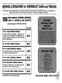
SERVICE LITERATURE for CHEVROLET CARS and TRUCKS
The following Chevrolet publications coverin g the operation and servicing of Chevrolet Vehicles can be purchased by
filling out the order form and mailing it with check or money·order payable to Helm Inc.
1966
SHOP MANUALS COVERING CHEVROLET,
CHEVY II, CHEVELLE AND CORVETTE
(See following page for 1966 Corvair and Truck)
Price Each
ST·72 (1966) SERVICE MANUAL
Includes on-the-car adjustment, maintenance and
overhaul of minor assembles and specifications. (e.g.
windshield washers, distributor, etc. Will handle most
owner's requirements.)
54.25
ST·56 (1965) SERVICE MANUAL·
$4.25
ST.73 (1966) OVERHAUL MANUAL
Includes basic off·the-car overhaul of major assemblies
(e.g. engine, transmission, axle, etc.)
$3.50
-------------------------------$3.50
ST-57 (1965) OVERHAUL MANUAL·
H·60 (1966) BODY SERVICE MANUAL
Includes all information for car bodies (except Cor·
vette, which is in ST·72 Service manual).
$2.75
--------------------------r----54.50
ST·58 (1965) BODY SERVICE MANUAL·
-Excluding 1965 Corvette (see following page)
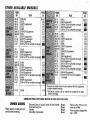
OTHER AVAILABLE MANUALS LISTED ON NEXTfrA1
OTHER AVAILABLE MANUALS
FORM
NO.
YEAR
$4.50
Supplement
coverage)
coverage)
l(i959:6,O*) Supplement
mU~:~:~~~~~~~1::,ete
(1954)
(1955)
S&IM,"", (1956*) Supplement
(1957)
(1958)
'&M"", (1959*) Supplement
".0"2<1 (1960)
(1960·62*>' Supplement
(1963)
(1964 Supplement)
coverage)
iii
2.00
IIIiIIB
3.75
3.25
3.00
(1964 wl'6~Jor complete coverage)
(1965 Supplement)
(1965 w/,63 for complete coverage)
(1966 Supplement)
(1966 w/, 63
complete
'P,'evious
4 .75
COMBINATION PRICES
OWNER GUIDES
Please, specify model year and
vehicle when ordering.
APP~Y
co;npi,";;;;oii_,,;•• :1 must be ordered with this supplement
"1961 Model mari_ual must be ordered with supplement to obtain
complete coverage.
WHERE INDICATED IN
B~CK
PRICE BOXES ABOVE.
Chevrolet, Chevy II. Cor'vair. Corvair95 and Chevelle
Truck and Chevy Van
Corvette
Convertible Top Booklets
.30 ,a,ch
.40 tach
.60 tach
.25 each
Please allow 30 days for
orders to be filled •
Prices subject to chanae after
July 1, 1966,
I
II ..
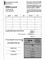
Please mail Check or Money Order (NO STAMPS)
NOTE: Plea se fill order form in completely,
~ cut here _and MAIL TO:
I
for the pUblications you have ordered on th is form.
HELM Incorporated
NOTE: Purchasers outside Domestic U.S.A. mu st
add 30¢ .to each publication -f or mailing expe nse.
Funds MUST be payable in U.S. CURRENCY.
POST OFFICE BOX 7706
OETROIT, MICHIGAN 48207
All order-s will be mailed within 10 days of receipt of
order. Please allow approximately 30 days f or postal
service.
QUANTITY
FORM NO.
YEAR
PRICE EACH
TOTAL
-
--
.
.
.
.'
'.
.
.
-
Space provided for addlti,onal information 0'" reverse of this order blank.
-
Total Order
(of both colum ns)
Ml ch loan Purchasers-Add 4% SIIIOI Te_
-+ Michigan Sale' Tax
Grand Tota l
This is your s hipping la bel- Pleas . print clearly •
PLEASE COMPLETE SHIPPING LABEL
SIgnatu re of Purchaser
~t reet
Address
City, Postal Zone, State
.
CHEVROLET OWNER PROTECTION PLAN
The Chevrolet Motor Division considers it a most important obligation to offer
each owner a recommended maintenance service guide which will relieve him
of any anxiety and insure that his vehicle is regularly inspected and maintained.
Your Chevrolet dealer has presented you with a Chevrolet Owner Protection
Plan Booklet. The recommended Maintenance and Lubrication Service items
in this Booklet have been worked out by Chevrolet service personnel and
cover items which are the owners responsibility to have checked, inspected,
adjusted and lubricated at recommended time or mileage intervals.
If the services are carried out at the prescribed time or mileage intervals,
wear and owner expense will be kept to , a minimum. Additional services may
become necessary as 'mileage accruesl however, the regular visit that you make
to yaur Chevrolet dealer in following this Plan will point out desirable services
as they become necessary.
In the event warranty repair is required on your Chevrolet, the Chevrolet
Protect-O-Plate affixed to the back cover of your Protection Plan Booklet will
assist in identifying you and your Chevrolet to your Chevrolet dealer.