1
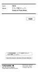
User’s
Manual
CW10
クランプ電力チェッカ
Clamp-on Power Meter
保証書付
この取扱説明書は、いつでも使用できるよう
大切に保管してください。
Store this manual in an easily accessible place
for quick reference.
IM CW10-JA: Japanese
IM CW10-EN: English
5th Edition: April 2015 (YMI)
Regarding the Safe Use of This Product
When operating the instrument, be sure to observe the cautionary
notes given below to ensure correct and safe use of the instrument.
If you use the instrument in any way other than as instructed in
this manual, the instrument’s protective measures may be impaired.
YOKOGAWA is by no means liable for any damage resulting from
use of the instrument in contradiction to these cautionary notes.
The following safety symbols are used on the instrument and in
this manual.
Danger! Handle with Care.
This symbol indicates that the operator must refer to an
explanation in the User’s Manual in order to avoid risk of
injury or death of personnel or damage to the instrument.
Hazardous Voltage
This operator must never attempt to touch equipment or
parts marked with this symbol.
This symbol indicates double insulation or reinforced
insulation.
This symbol indicates direct current (DC).
This symbol indicates aiternating current (AC).
This symbol indicates ground (earth).
This symbol indicates a battery.
This symbol indicates that this instrument designed to be
applied around or removed from HAZARDOUS LIVE
conductors provided if the RATED circuit-to-earth voltage
dose not exceed the value indicated in the measurement
category.
This symbol indicates, If the measured voltage is
greater than 30 V DC or AC RMS or Overload
(OL or –OL).
Indicates a hazard that may result in the loss of life
or serious injury of the user unless the described
instruction is abided by.
Indicates a hazard that may result in an injury to
the user and/or physical damage to the product or
other equipment unless the described instruction is
abided by.
1
Always observe the following instructions. Failure to do so may result
in electrical shock or other dangers that may lead to serious
injury or the loss of life.
• The instrument is a power measurement instrument that can measure
parameters such as voltage, current, and power.
Do not use this instrument for any other purpose.
• Do not use the instrument if there is a problem with its physical
appearance.
• Do not use the instrument in an atmosphere where any flammable or
explosive gas is present.
• To avoid a short-circuit or an accident to personnel, use this instrument
within the RATED circuit-to-earth voltage, maximum input voltage and
current.
• Avoid using the instrument if it has been exposed to rain or moisture or
if your hands are wet.
• Barrier is for to avoid touching the HAZARDOUS LIVE conductor.
Be careful not to across the Barrier when using the instrument.
• Do not use the instrument if there is any damage to the casing or
when the casing is removed.
• Use the test leads supplied by Yokogawa with this instrument.
• Do not use test leads that have deteriorated or are defective.
• Check the test leads continuity.
• When you attach or remove the test leads or remove the case
(for example to charge the battery), be sure to remove the test leads
from the circuit under measurement.
• When you remove the case (for example to change the battery),
be sure to remove the test leads from the instrument.
• Safety protectors such as rubber-insulated gloves should be worn to
prevent electrical shock when using the instrument.
• There are caps at the ends of the test leads. To ensure safety
(safety standard EN 61010-031), be sure to put the caps on the leads
when you use them.
• No person, except personnel from Yokogawa, is authorized to
disassemble this instrument.
Do not attempt to repair/modify the instrument yourself,
as doing so is extremely dangerous.
• The product is for domestic use (Class B) and meets the electromagnetic
compatibility requirements.
• Do not use the instrument near noise-emitting equipment or where
there may be sudden changes in temperature. Otherwise,
the instrument may produce an unstable readings or errors.
• Do not wipe the instrument using an organic solvent.
When cleaning the instrument, use a dry cloth.
• Do not leave the tester exposed to direct sunlight or in a hot and humid
location such as the inside of a car, for any prolonged length of time.
• If the instrument will not be used for long periods, remove the battery.
2
Contents
Regarding the Safe Use of This Product . . . . . . . . . . . . . . . . . . . . . . . 1
1. Checking the Contents of the Package . . . . . . . . . . . . . . . . . . . . . 4
2. Measurement Category . . . . . . . . . . . . . . . . . . . . . . . . . . . . . . . . . 4
3.Components . . . . . . . . . . . . . . . . . . . . . . . . . . . . . . . . . . . . . . . . . 5
4. Display (LCD) . . . . . . . . . . . . . . . . . . . . . . . . . . . . . . . . . . . . . . . . 6
5. Power ON/OFF and Auto power off . . . . . . . . . . . . . . . . . . . . . . . . 6
6. Cursor/ENTER key . . . . . . . . . . . . . . . . . . . . . . . . . . . . . . . . . . . . 6
7. Making Basic Measurements . . . . . . . . . . . . . . . . . . . . . . . . . . . . 7
7.1 Measuring Voltage . . . . . . . . . . . . . . . . . . . . . . . . . . . . . . . . 7
7.2 Measuring Current . . . . . . . . . . . . . . . . . . . . . . . . . . . . . . . . 7
8. Others Function . . . . . . . . . . . . . . . . . . . . . . . . . . . . . . . . . . . . . . . 8
8.1 AUTO SENSE . . . . . . . . . . . . . . . . . . . . . . . . . . . . . . . . . . . 8
8.2RANGE . . . . . . . . . . . . . . . . . . . . . . . . . . . . . . . . . . . . . . . . 8
8.3 Peak Hold (AC mode only) . . . . . . . . . . . . . . . . . . . . . . . . . . 9
8.4 Inrush current (AC mode only) . . . . . . . . . . . . . . . . . . . . . . 11
8.5 DCA ZERO . . . . . . . . . . . . . . . . . . . . . . . . . . . . . . . . . . . . . 12
8.6 Measuring Frequency Hz (AC mode only) . . . . . . . . . . . . . 12
8.7MAX/MIN . . . . . . . . . . . . . . . . . . . . . . . . . . . . . . . . . . . . . . 13
8.8 Harmonic Measurement (AC mode only) . . . . . . . . . . . . . 13
8.8.1 THD Measurement . . . . . . . . . . . . . . . . . . . . . . . . . . 13
8.8.2 Individual Harmonic Mesurement . . . . . . . . . . . . . . . 14
8.9 Low pass filter (AC mode only) . . . . . . . . . . . . . . . . . . . . . 14
8.10 Measuring Active Power . . . . . . . . . . . . . . . . . . . . . . . . . . . 15
8.10.1 Single phase 2 wire . . . . . . . . . . . . . . . . . . . . . . . . . . 15
8.10.2 3 phase 3 wire (balanced/unbalanced) . . . . . . . . . . . 16
8.10.3 3 phase 4 wire (balanced/unbalanced) . . . . . . . . . . . 16
8.10.4 Phase Rotation . . . . . . . . . . . . . . . . . . . . . . . . . . . . . 17
8.11 Mesuring Resistance . . . . . . . . . . . . . . . . . . . . . . . . . . . . . 19
8.11.1 Resistance (Ω) . . . . . . . . . . . . . . . . . . . . . . . . . . . . . . 19
8.11.2 Continuity Check . . . . . . . . . . . . . . . . . . . . . . . . . . . . 20
8.11.3 Diode Test . . . . . . . . . . . . . . . . . . . . . . . . . . . . . . . . . 20
8.12HOLD . . . . . . . . . . . . . . . . . . . . . . . . . . . . . . . . . . . . . . . . . 20
8.13 Voltage Sanse . . . . . . . . . . . . . . . . . . . . . . . . . . . . . . . . . . 20
8.14 Buzzer . . . . . . . . . . . . . . . . . . . . . . . . . . . . . . . . . . . . . . . . 21
8.15 Additional Power-on Function . . . . . . . . . . . . . . . . . . . . . . 21
9. Battery State display and Battery Replacement . . . . . . . . . . . . . 21
9.1 Battery State display . . . . . . . . . . . . . . . . . . . . . . . . . . . . . 21
9.2 Bayttery Replacement . . . . . . . . . . . . . . . . . . . . . . . . . . . . 21
10.Specifications . . . . . . . . . . . . . . . . . . . . . . . . . . . . . . . . . . . . . . . 22
10.1 General Specifications . . . . . . . . . . . . . . . . . . . . . . . . . . . . 22
10.2Accuracy . . . . . . . . . . . . . . . . . . . . . . . . . . . . . . . . . . . . . . 23
11. Maintenance and After-Sales Service . . . . . . . . . . . . . . . . . . . . . 26
12. Sales in Each Country or Region . . . . . . . . . . . . . . . . . . . . . . . . 26
12.1 Disposing the Product . . . . . . . . . . . . . . . . . . . . . . . . . . . . 26
12.2 How to Replace and Dispose the Batteries . . . . . . . . . . . . 26
12.3 Authorized Representative in the EEA . . . . . . . . . . . . . . . . 26
12.4 For the Pollution Control of Electronic and
Electrical Products of the People's Republic of China . . . . 27
Disk No. CW10
5th Edition: April 2015
All Rights Reserved, Copyright ©2011,
Yokogawa Meters & Instruments Corporation
Printed in Taiwan
3
1. Checking the Contents of the Package
After opening the package, be sure to check the product as
instructed below before use.
1. Main Unit: CW10 (including battery)
2. Test leads: 1set (Black and Red)
3. User’s Manual
4. Soft Case
2. Measurement Category
When you use the test leads, attach or remove the caps
according to the measurement category.
CW10 main unit:
1000V CAT III, 600V CAT IV
Test leads:
With Caps:
1000V 10A CAT III, 600V 10A CAT IV
Without Caps: 1000V 10A CAT II
Measurement
Category
O
Description
Remarks
Other circuits that are not
directly connect to MAINS.
Circuits not
connected to a
mains power source.
CAT II
For measurement performed
on circuits directly connected
to the low-voltage installation.
Appliances,
portable equipment,
etc.
CAT III
For measurement performed
in the building installation.
Distribution board,
circuit breaker, etc.
CAT IV
For measurement performed
Overhead wire,
at the source of the low-voltage
cable systems, etc.
installation.
None
Other
4
3. Components
CW10
Test leads
1.Jaw section
2.Light
3.Voltage sense
LED
4.Barrier
Caps of Test leads
5.Hold and Zero key
6.Function switch
7.Open/
close lever
8.LCD display
9.Cursor/
Enter key
Black
Red
10.Terminals of test leads
Main Unit: CW10
1.
2.
3.
4.
5.
6.
7.
8.
9.
10.
Is a precision sensor for detecting currents.
When the jaws are open, the light will illuminate.
In case voltage is detected by the jaw, the red LED lights up.
Prevents contact with the wires.
Retains the measured data or DCA ZERO: Zero adjustment
Use this switch to turn the power on and off and to select
the measurement mode.
Opens and closes the jaws.
LCD display
Cursor and Enter key
Input terminals for test leads
[NOTE]
There is the
mark on the terminal, but this device does not
have a function for measuring capacitance.
5
4. Display (LCD)
5. Power ON/OFF and Auto power off
Check that the meter operates normally.
Turn the function switch to the measurement (any) position from OFF.
To end measurement, turn the function switch off.
<Auto power off>
Indication: APO
This instrument automatically turns off about 15 minutes after
the last switch operation.
Recovering the Auto power off function:
Turn off the power. Turn on the power.
Turn off the power. Hold down Downward of cursor key,
turn the function switch to any position.
(The APO display goes off.)
If the instrument is used with the Auto power off function
cancelled, take care not to let the battery run down.
When the function is not use (cancellation):
6. Cursor/ENTER key
UP
UP
LEFT
ENTER
RIGHT
DOWN
Cursor key:
Moves the Cursor (four directions) to the item (mode)
of display you wish select. Press the convex key
toward selecting mode.
ENTER key: Confirms the item (mode).
[NOTE]
Push whole key toward requisite item.
Push down the center position of key to confirm (ENTER key).
6
7. Making Basic Measurements
7.1
Measuring Voltage
Do not apply more than 1000 VDC or 1000 Vrms (1414.2 Vpk).
Plug the test leads to the input terminals.
[NOTE]
When connecting the test leads to the circuit under measurement,
connect the black (common) before connecting the red (live);
when removing the test leads, remove the red (live) before
removing the black (common).
Turn the function switch to the Voltage
position.
Read the voltage value of display.
On Auto Sense mode, the CW10 automatically detects AC or DC.
DC
AC
Red
Black
Test leads
7.2
Measuring Current
• Do not apply more than 600 ADC or 600 Arms (848.5 Apk).
• When you measure the current, be sure to remove the test leads
from the instrument.
Squeeze the open/close lever to open the jaws. Insert a wire from the
measurable conductors under the test though the jaws, making sure
the tops of the jaws are tightly shut.
Turn the function switch to the Current
position.
Read the current value of display.
Using Auto Sense mode, the CW10 automatically detects AC or DC.
[NOTE]
• When performing a measurement, hold the instrument so that
the measured conductor cable runs at the center of the clamp.
• Ensure that the orientation of the clamp to the direction of
the conductor wire is correct as shown right.
7
DC
AC
8. Others Function
8.1
AUTO SENSE
Using Auto Sense mode, the CW10 automatically detects AC or DC.
(The detection is determined by whichever input is greater.)
To select manual mode (Example: DC mode);
Use the cursor key to select under “DC” (flash) and then press the
ENTER key to confirm.
Upper “DC” indication is fixed and AUTO (AUTO RANGE) is displayed.
To return AUTO SENSE, press the ENTER key
for more than 2 seconds.
8.2
RANGE
To select manual range (fixed);
Use the cursor key to select “RANGE” and then press the ENTER key
to confirm.
(To cancel manual range, press the ENTER key
for more than 2 seconds.)
Example: ACV 100 V range ← → 1000 V range
ENTER
On Auto sense mode, the measuring range is automatic.
8
8.3
Peak Hold (AC mode only)
(1) AC Voltage
Turn the function switch to the voltage (V) position.
After using the ENTER key to confirm AC mode, use the cursor key to
select Peak Hold
and then press the ENTER key to confirm.
Press the ENTER key to switch between PEAK MAX (polarity+) and
PEAK MIN (polarity-).
(To cancel Peak Hold, press the ENTER key
for more than 2 seconds.)
"ENTER"
>2SEC
[NOTE]
Bar-graph indication is not PEAK value.
Bar-graph indication is affected by the ACV value.
(Example: 500.0 V)
9
(2) AC Current
Turn the function switch to the current (A) position.
After using the ENTER key to confirm AC mode,
use the cursor key to select Peak Hold.
Press the ENTER key for more than 2 seconds
to select PEAK MAX.
Press the ENTER key to switch between PEAK MAX (polarity+) and
PEAK MIN (polarity-).
(To cancel Peak Hold, press the ENTER key
for more than 2 seconds.)
[NOTE]
Bar-graph indication is not PEAK value.
Bar-graph indication is affected by the ACA value.
(Example: 500.0 A)
>2SEC
"ENTER"
>2SEC
10
8.4
Inrush current (AC mode only)
The CW10 has a function for measuring Inrush current.
Turn the function switch to the current
position.
Using the ENTER key to confirm AC mode.
(Inrush current) and
Using the cursor key to select Peak Hold
then press the ENTER key to confirm. (INRUSH)
Waiting state, after trigger, the Inrush current value (RMS)
for 100m seconds (measurement period) is displayed.
Press the ENTER key once to return ACA mode.
Press the ENTER key once again to return waiting state (restart).
[NOTE]
If the Inrush current is expected to exceed 100 ACA,
select 600 A range in advance of measuring.
A
30.0A
10.0A
0.0A
<2>
<1>
100msec
Motor
Off
Trigger
Point
Time
Motor
On
Waiting Trigger
<1>
After Trigger
ENTER
<2>
11
8.5
DCA ZERO
We recommend that you perform zero adjust (DCA ZERO) before
measuring DCA mode.
[NOTE]
Remove the jaws out of the conductor.
Press the HOLD key of right side for more than 2 seconds.
After ”----“ is displayed, ZERO adjustment is confirmed.
DCA Zero is only available in AUTO SENSE, DC and AC+DC mode.
HOLD> 2 Sec
HOLD
8.6
Measuring Frequency Hz (AC mode only)
<1> Turn the function switch to the voltage
or
position.
current
<2> Using the ENTER key to confirm AC mode.
<3> Using the cursor key to select “Hz” and then
press the ENTER key to confirm.
(The unit of Hz and the frequency value are displayed.)
Using ENTER key to change unit (to cancel).
"Hz"
ENTER
< RANGE >
On measuring frequency, Using the cursor key to select “RANGE” and
then press the ENTER key to confirm. The frequency range is fixed.
Each time “RANGE” (ENTER) key is pressed, range is changed.
On measuring frequency, ACV or ACA range is fixed.
12
8.7
MAX/MIN
The minimum and maximum value during measurement are updated
(displayed).
Using the cursor key to select “MAX/MIN” and then
press the ENTER key to MAX/MIN mode.
(To cancel the function, press the ENTER key
for more than 2 seconds.)
[NOTE]
HOLD key is pressed in MAX/MIN mode, the MAX and MIN
values are not updated. (“HOLD” is appeared)
To cancel the function, press the HOLD key again.
8.8 Harmonic Measurement (AC mode only)
8.8.1 THD Measurement
Harmonic measurements (fundamental wave to 25th harmonics) can
be displayed. In ACV or ACA mode (after confirming AC using the
ENTER key), use the cursor key to select “THD,” and then press the
ENTER key to confirm.
Press the ENTER key to toggle between the rms value and the
distortion factor.
25
THD-F=
∑ (nth order harmonic voltage(current) rms value) 2
n=2
(fundamental wave voltage(current) rms value) 2
"THD"
"ENTER"
13
×100%
8.8.2
Individual Harmonic Mesurement
Harmonic measurements individual order (fundamental wave to 25th)
can be displayed. In ACV or ACA mode (after confirming AC using the
, and then
ENTER key), use the cursor key to select
press the ENTER key to confirm.
(To cancel the function, press the ENTER key
for more than 2 seconds.)
Hn=
nth order harmonic voltage (current) rms value
×100%
fundamental wave voltage (current) rms value
ENTER
>2SEC
"RIGHTWARD"
"LEFTWARD"
"UPWARD"
"UPWARD"
"DOWNWARD"
"DOWNWARD"
"RIGHTWARD"
"LEFTWARD"
8.9
Low pass filter (AC mode only)
The CW10 has a function for turning the filter on (use) /off.
On ACV or ACA mode (using ENTER key to confirm AC),
Using the cursor key to select “LPF” and then
press the ENTER key to confirm.
"LPF"
ENTER
[NOTE]
Cut of frequency: approximately 1 kHz
14
8.10 Measuring Active Power
• Do not apply more than 1000 VDC or 1000 Vrms (1414.2 Vpk).
• Do not apply more than 600 ADC or 600 Arms (848.5 Apk).
8.10.1 Single phase 2 wire
600A
+Line
Load
Power source
<1> Turn the function switch to the Active power
position.
<2> Connect the red test lead to Line (+) and the black test lead to N (-).
<3> Squeeze the open/close lever to open the jaws and clamp them
onto the wire under test. (Ensure that the jaws are properly closed
and the conductor runs thru the center of the clamp.)
<4> When measuring Active power:
Use the cursor key to select “W” and then
press the ENTER key to confirm.
When measuring Power factor:
Use the cursor key to select “PF” and then
press the ENTER key to confirm.
600V
-N
"PF"
"W"
ENTER
No.1
W1
[NOTE]
• The “ + ” symbol on the jaw must face on the power source side.
• In Auto sense mode, The CW10 can detect ACW or DCW automatically.
Overload (over range) Description
OL.U: Voltage overload
OL.A: Current overload
OL.UA: Both Voltage and current overload.
OL kW, -OL kW: Active Power > 1000 kW or < -1000 kW.
Active power polarity
Non-display (+):
Indicates the power flows from the power source to the load.
Minus (-):
Indicates the power flows from the load to the power source.
Power factor polarity
Non-display (+):
Minus (-): The phase of the current signal is lagging behind
the voltage signal (inductive load).
The phase of the current signal is leading the
voltage signal (capacitive load).
15
8.10.2 3 phase 3 wire (balanced/unbalanced)
To use two the CW10
<1> Turn the function switch to the Active power
<2> Connect following connecting diagram.
<3> Use the cursor key to select "W" and then
press the ENTER key to confirm.
position.
Active power (W) = W1+W2: sum total
1
3
3P3W
W=W1+W2
2
Y(star-connection),
Delta-connection
Red
No.2
W2
Red
Black
No.1
W1
Black
8.10.3 3 phase 4 wire (balanced/unbalanced)
To use three the CW10
<1> Turn the function switch to the Active power
<2> Connect following connecting diagram.
<3> Use the cursor key to select "W" and then
press the ENTER key to confirm.
Active power (W) = W1+W2+W3: sum total
16
position.
3P4W
W=W1+W2+W3
1
N
2
Red
Black
3
Red
Black
Red
No.1
W1
No.2
W2
Black
No.3
W3
8.10.4 Phase Rotation
The CW10 can measure (test) phase rotation.
(Only if the system frequency is stable.)
<1> Turn the function switch to the Active power
position.
<2> Use the cursor key to select “RST” and then
press the ENTER key to confirm.
<3> Connect the red test lead to the phase Line1and the black test
lead to the phase Line3.
If connecting is normal, “L1” is displayed
(flash for about 3 seconds.)
Indication
(flash)
Condition
OLU
Voltage > 1000 V
LoU
Voltage < 30 V
outF
Frequency < 45 Hz, 65 Hz < Frequency
17
Line 1
Red
Black
Line 2
Black
Line 3
Red
No.1
No.1
<4> “L2” is displayed and then buzzer beeps twice.
Switch over the red test lead to connect to the phase Line2
immediately before “L2” disappears.
<5> After “L2” disappears, the following testing result is displayed.
Indication
(testing result)
Explanation
123
Forward sequence;
The phase Line1 is ahead of Line2.
321
Reversed sequence;
The phase Line2 is ahead of Line1.
----
It is not possible to judge.
LoU
It is possible that you remove the test
leads before completing the whole
testing procedures.
<6> To repeat the test, use the cursor key to select “RST” again
and then press the ENTER key to confirm.
18
8.11 Mesuring Resistance
To avoid damage to instrument
Turn off the power to the circuit under test before starting
measurement in order to prevent any excessive voltage from
being applied to the instrument.
On measuring resistance
, use AUTO SENSE mode to measure
three items automatically: Resistance, Continuity check and Diode test
[NOTE]
Maximum open circuit voltage;
Resistance (continuity check): approximately +3 V
Diode test: approximately -1.8 V, +1.8 V
Manual setting (When you do not use the AUTO SENSE)
8.11.1 Resistance (Ω)
<1> Turn the function switch to the Resistance position.
<2> Plug the test leads to terminals.
<3> Use the cursor key to select Resistance Ω and then
press the ENTER key to confirm.
<4> Read the measured value.
(To return AUTO SENSE, press the cursor key for more
than 2 seconds)
[NOTE]
To measure manual range (the range is fixed), use the cursor key to
select RANGE and then press the ENTER key to confirm.
Function switch
Resistance
position
Continuity
Buzzer(Beep)
Red
Black
Red +
Test leads
Black -
Test leads
Diode Test
Forward-bias
Red
Reverse-bias
Red
Black
Test leads
Black
Test leads
19
8.11.2 Continuity Check
<1> Turn the function switch to the Resistance position.
<2> Plug the test leads to terminals.
and then
<3> Use the cursor key to select Continuity check
press the ENTER key to confirm.
[NOTE]
At 1000 Ω range (continuity check), the buzzer turns on for
resistances lower than approx. 30Ω.
8.11.3 Diode Test
<1> Turn the function switch to the Resistance position.
<2> Plug the test leads to terminals.
<3> Use the cursor key to select Diode test
and then
press the ENTER key to confirm.
[NOTE]
The “bad” is displayed when measuring a diode conducted at
forward and reverse bias.
8.12 HOLD
Press the HOLD key (right side) to hold the measured value.
To cancel, press the HOLD key again.
Press
Hold key
[NOTE]
On ACA mode, Press the HOLD key for more than 2 seconds
for zero adjust. See also: Section 8.5 DCA ZERO
Alarm during Hold
The CW10 beeps continuously and the display will flash
if the measured signal is larger than the display reading.
(at Voltage, Current and Active power function)
To cancel, press the HOLD key.
8.13 Voltage Sanse
Even if Voltage Sense LED does not light, do not touch unshielded
wire/cable with bare hand.
In case voltage is detected by the jaw, the red LED lights up.
Ensure that the tip of the jaw touches the object wire.
Take care that the tip of the jaw does not touch other wires.
Use the Voltage Sense LED as an aid only if wire is energized or not.
Live wire
Voltage Sense
LED
20
8.14 Buzzer
The CW10 beeps once for every valid key-press (operation),
and beeps twice for every invalid key-press.
8.15 Additional Power-on Function
Hold one of the keys below, and turn the function switch
from OFF to any position to configure various function.
Key
Configured Function
Upward of
Cursor key
Display of the software version.
Example: c128
Downward of
Cursor key
Disable (cancel) Auto power off.
Leftward of
Cursor key
Disable (cancel) Backlight.
HOLD key
(ZERO)
Display all LCD symbols approx. 10 sec.
9. Battery State display and Battery Replacement
9.1
Battery State display
A decrease in the battery voltage is displayed in
the following four steps.
Replace the battery as soon as the low battery (4 Replacement)
indicator appears, to avoid inaccurate reading.
1
2
3
4
Full
9.2
2/3
1/3
Replacement
Bayttery Replacement
• Turn the function switch to OFF and remove the test leads before
the battery case is opened.
• Insert the battery correctly to the holder with their polarities.
<2>
<3>
<1>
21
10. Specifications
10.1 General Specifications
Display count: Measuring rate:
Over range indicator:
Auto Power Off:
9999 / 6000
3 times / sec.
“OL” or “-OL”
Approx. 15 minute.
(four steps)
Low-battery indicator:
Power supply:
9V alkaline battery (6LR61)
Battery life:
When using alkaline battery, backlight off
Approx. 20 hours
Operating temperature and humidity:
0 to 50 °C (with no condensation)
≤ 80% RH (0 to 30 °C)
≤ 75% RH (30 to 40 °C)
≤ 45% RH (40 to 50 °C)
Temperature coefficient: At 0 to 18 °C and 28 to 50 °C
Add 23±5 °C accuracy × 0.2 / °C
Storage temperature: -10 to 50 °C, 80% RH or less (remove the battery)
Withstand voltage:
AC 6880 Vrms 5 seconds (between the core and the case)
AC 4300 Vrms 5 seconds
(between the core and the voltage input terminals)
AC 6880 Vrms 5 seconds
(between the voltage input terminals and the case)
Insulation resistance: 100 MΩ or greater at 1000 VDC
(between the core and the case,
the core and the voltage input terminals and
the voltage input terminals and the case)
Safety standards:
EN61010-1, EN61010-2-033, EN61010-2-032
1000 V CAT III, 600 V CAT IV
EN61010-031 (the test leads)
Pollution degree 2, indoor use,
altitude 2000m or less
EMC standards:
EN61326-1 Class B,
EN61326-2-1, EN61326-2-2,
EMC Regulatory Arrangement in Australia and
New Zealand
EN55011 Class B Group 1
Korea Electromagnetic Conformity Standard
(한국 전자파적합성기준)
Environmental standard: EN50581 Monitoring and control instruments
Dimensions:
Approx. 87.5 mm (W) × 242 mm (L) × 51 mm (D)
37mm (Maximum)
Diameter of measurable conductors:
Weight:
Approx. 435g (including the battery)
Accessories: Test leads 1set (Red and Black)
Soft case: 93044
9V alkaline battery (6LR61)
User’s Manual
22
10.2 Accuracy
23± 5°C, 80%RH or less
Accuracy: ±(% of reading + digits)
(1) Voltage
Function
DCV
ACV
LPF
ACV
Range
Rms-value detection
Resolution
(Maximum reading)
100 V
1000 V
100 V
1000 V
100 V
1000 V
99.99 V
999.9 V
99.99 V
999.9 V
99.99 V
999.9 V
Accuracy*
0.7% + 2
1.0% + 5
50 ≤ f ≤ 500 Hz
50 ≤ f ≤ 60 Hz: 1.0% + 5
60 < f ≤ 400 Hz: 5.0% + 5
* DCV<1000 digits: add 6 digits to accuracy
ACV<1000 digits: add 3 digits to accuracy
Maximum input voltage: 1000 Vrms, 1414.2 Vpk
Input impedance: approx. 3.5MΩ, <100pF
AC+DC accuracy = ACV accuracy + DCV accuracy
Crest factor effects
1.4< CF≤ 2.0: add 1.0% of reading to accuracy
2.0< CF≤ 2.5: add 2.5% of reading to accuracy
2.5< CF≤ 3.0: add 4.0% of reading to accuracy
Maximum input voltage 690 Vrms CF=2, 460Vrms CF=3
(2) Current
Function
DCA
ACA
LPF
ACA
Range
100 A
600 A
100 A**
600 A
100 A**
600 A
Rms-value detection
Resolution
(Maximum reading)
99.99 A
600.0 A***
99.99 A
600.0 A***
99.99 A
600.0 A***
Accuracy
1.5% + 20
1.5% + 5*
50 ≤ f ≤ 60 Hz: 1.5% + 5*
60 < f ≤ 400 Hz: 2.0% + 5*
50 ≤ f ≤ 60 Hz: 1.5% + 5*
60 < f ≤ 400 Hz: 5.0% + 5*
* The measured value <1000 digits: add 5 digits to accuracy
** Input current ≥ 0.10A at 100 A range of ACA and LPF ACA
*** 600 A : Guaranteed accuracy (not maximum reading)
Maximum input current: 600 Arms, 848.5Apk
Conductor position effects: ±1.0% of reading
AC+DC accuracy = ACA accuracy + DCA accuracy
Crest factor effects
1.4< CF≤ 2.0: add 1.0% of reading to accuracy
2.0< CF≤ 2.5: add 2.5% of reading to accuracy
2.5< CF≤ 3.0: add 4.0% of reading to accuracy
Maximum input current: 420 Arms CF=2, 280 Arms CF=3
DCA accuracy: after DCA zero adjustment
23
(3) Peak Hold (AC mode only)
Function
ACV
ACA
Range
Resolution
(Maximum reading)
100 V
1000 V
100 A
600 A
140.0 V
1400 V
140.0 A
850 A
Accuracy
3.0% + 15
3.0% + 15
PEAK MAX: polarity+, polarityMaximum input voltage and current: 1000 Vrms, 600 Arms
Sine wave, ACV > 5 Vrms, ACA ≥ 5 Arms, 50 to 400 Hz continuous wave
(4) Frequency (Hz)
Resolution
Function
100 Hz
1000 Hz
10 kHz
Accuracy
(Measuring reading)
20.00 to 99.99 Hz
20.0 to 999.9 Hz
0.020 to 9.999 kHz
0.5% + 3
Maximum input voltage and current:
1000 Vrms, 600 Arms
Input condition; (Sine wave)
100 V range: 10 to 100 Vrms
1000 V range: 100 to 1000 Vrms
100 A range: 10 to 100 Arms ( < 400 Hz )
600 A range: 100 to 600 Arms ( < 400 Hz )
The measured value < approx. 10 Hz: 0.00Hz
(5) Harmonic Measurement
Indiviual Harmonic
Harmonic
order
1st to12th
(h01-h12)
13th to 25th
(h13-h25)
Resolution
(Maximum reading)
Accuracy
5% + 10
99.9 %
10% + 10
Maximum input voltage and current: 1000 Vrms, 600 Arms
The “rdy” is displayed at ACV < 10 Vrms, ACA < 10 Arms
The “OutF” is displayed at f < 45 to 65 < f (f: fundamental frequency)
(6) Inrush Current
Function
ACA
Range
100 A
600 A
Resolution
(Maximum reading)
99.99 A
600.0 A*
Accuracy
2.5% + 20
2.5% + 5
Maximum input current: 600 Arms
* 600 A : Guaranteed accuracy (not maximum reading)
100A range: ACA≥10 Arms (Sine wave, 50Hz/60Hz)
600A range: ACA≥100 Arms (Sine wave, 50Hz/60Hz)
Measurement time: approx. 100ms
24
(7) Active Power
Function
Range
ACW
DCW
10 kW
100 kW
600 kW
Resolution
(Maximum reading)
9.999 kW*
99.99 kW
600.0 kW**
Accuracy
ACW : 2.5% + 11***
DCW : 2.2% + 22***
* The measured value<1.000 kW: add 10digits to the accuracy.
** 600 kW: Guaranteed accuracy (not maximum reading)
*** Conditions of accuracy (combination of Voltage and Current range)
10 kW range: 100 V and 100 A
100 kW range: 100 V and 600 A or 1000 V and 100 A
600 kW range: 1000 V and 600 A
Other combinations:
Accuracy: (Current accuracy × Voltage reading) +
(Voltage accuracy × Current reading)
Maximum input voltage and current: 1000 Vrms, 600 Arms
ACW : ACV≥10 Vrms and ACA≥5 Arms
(Sine wave, 50 ≤ f ≤ 60Hz, PF=1.00)
DCW : at DCV≥10 V and DCA≥5 A, after DCA zero adjustment
(8) Power Factor
Function
Power
factor
Resolution
(Measuring reading)
-1.00 to 0.00 to 1.00
Accuracy
±(3°+ 2 digits)
Maximum input voltage and current: 1000 Vrms, 600 Arms
PF: ACV≥10 Vrms and ACA≥5 Arms (Sine wave, 50 ≤ f ≤ 60Hz)
(9) Resistance/Continuity check
Function
Resistance
Ω
Continuity
check
Range
1000 Ω
10 kΩ
100 kΩ
1000 Ω
Resolution
(Maximum reading)
999.9 Ω
9.999 kΩ
99.99 kΩ
999.9 Ω
Accuracy
1.0% + 5
1.0% + 3
1.0% + 5
The buzzer turns on for resistances lower than
approx. 30Ω.
(Response time: approx. 100m sec)
Maximum input voltage: 1000 Vrms
Maximum test current: approx. 0.5 mA
Open circuit voltage: approx. 3 V
(10)Diode Test
Function
Diode
Test
Resolution
(Measuring reading)
0.40 to 0.80 V
Maximum test current: approx. 0.5 mA
Open circuit voltage: approx. 1.8 V
25
Accuracy
±0.1 V
11. Maintenance and After-Sales Service
Please direct question about this product to the contact listed on the
“Inquiries” or to your nearest Yokogawa dealer.
Recommended calibration period: 1 year
12. Sales in Each Country or Region
12.1 Disposing the Product
Waste Electrical and Electronic Equipment (WEE),Directive
(This directive is valid only in the EU.)
This product complies with the WEEE directive marking requirement.
This marking indicates that you must not discard this electrical/
electronic product in domestic household waste.
Product Category
With reference to the equipment types in the WEEE directive,
this product is classified as a “Monitoring and Control instrumentation”
product.
When disposing products in the EU, contact your local
Yokogawa Europe B.V. office.
Do not dispose in domestic household waste.
12.2 How to Replace and Dispose the Batteries
EU Battery Directive
(This directive is valid only in the EU.)
Batteries are included in this product.
When you remove batteries from this product and dispose them,
discard them in accordance with domestic law concerning disposal.
Take a right action on waste batteries, because the collection system
in the EU on waste batteries are regulated.
Battery type: Alkaline dry cell
Notice:
This marking indicates they shall be sorted out and collected as
ordained in the EU battery directive.
How to remove batteries safely:
For further details, see “9.2 Battery Replacement”.
12.3 Authorized Representative in the EEA
Yokogawa Europe B.V. is the authorized representative of
Yokogawa Meters & Instruments Corporation for
this product in the EEA. (EEA: European Economic Area)
To contact Yokogawa Europe B.V., see the separate
list of worldwide contacts, PIM 113-01Z2.
26
12.4 For the Pollution Control of Electronic and
Electrical Products of the People's Republic of China
They are applicable only in China.
产品中有毒有害物质或元素的名称及含量
有毒有害物质或元素
部件名称
铅
汞
镉
六价铬
(Pb) (Hg) (Cd) (Cr (VI))
多溴联苯
(PBB)
多溴二苯醚
(PBDE)
框架(塑料)
×
○
○
○
○
○
线路板 ASSY
×
○
○
○
○
○
导线
×
○
○
○
○
○
电池
×
○
○
○
○
○
○ :表示该部件的所有均质材料中的有毒有害物质的含量均在 GB/T 26572
标准中所规定的限量以下。
× :表示该部件中至少有一种均质材料中的有毒有害物质或元素的含量超过
GB/T 26572 标准所规定的限量要求。
环保使用期限 :
该标识适用于 SJ/T 11364 中所述,在中华人民共和国销售的电子电气
产品的环保使用期限。
只要您遵守该产品相关的安全及使用注意事项,在自制造日起算的年限内,
则不会因产品中有害物质泄漏或突发变异,而造成对环境的污染或对人体
及财产产生恶劣影响。
注)
该年数为“环保使用期限”,并非产品的质量保证期。
零件更换的推荐周期、请参照使用说明书。
27
■ Notice Regarding This Manual
• Every effort has been made to ensure accuracy in the preparation of
this manual. However, should any errors or omissions come to the
attention of the user, please contact Yokogawa.
• The contents of this manual is subject to change without prior notice
because of improvement in performance or function.
• All rights reserved. No part of this manual may be reproduced in
any from without Yokogawa’s written permission.
28
各国や地域の当社営業拠点の連絡先は、
下記シートに記載されています。
PIM 113-01Z2: お問い合わせ先
国内海外の連絡先一覧
Contact information of Yokogawa offices worldwide is
provided on the following sheet.
PIM 113-01Z2:
Inquiries
List of worldwide contacts
Compliance with the Radio Waves Act (Republic of Korea)
This product complies with the Radio Waves Act (Republic of Korea).
Note the following when using the product in Republic of Korea.
The product is for domestic use (Class B) and meets the
electromagnetic compatibility requirements.
Registration No: KCC-REM-IMY-EEN301
Equipment Name:Clamp-on Power Meter
Trade Name:
Yokogawa Meters & Instruments Corporation
Manufacturer:
Yokogawa Meters & Instruments Corporation
Country of Origin: Taiwan