1
(233)
STEERING GEAR AND TIE RODS
SPECIFICATIONS
7-1
GROUP 7
STEERING GEAR AND TIE RODS
CONTENTS OF GROUP 7
Paragraph
7-1
7-2
7-3
7-4
7-5
Subie ct
Steering Gear and Tie Rod
Specifications .... . .. . . . . ... .. .
Descr iption of Steeri ng Gear a nd
Tie R od .. . . . . . . . . . . . . .. . . .. .
T ro u ble Diagnosis-Steering
Ge ar and Tie R od .. .. . . . . .. ..
Adjus t ment of Steer in g Gear a nd
Tie Rod . . . . . . . . . . . . . . . . .. . . .
Adjustment of S teer ing Wheel
Height . . . . .. . . .. . . . .. .. . . . . .
Page
Paragraph
7-1
7-6
7-7
7-2
7-8
7-4
7-9
7-5
7-10
Su b ject
Page
Steering Wheel Replacemen t . . . 7-7
R eplacement of Bearings in Signal
S wi tch Housing .. ....... . . . .. . 7-8
Removal of S teerin g Gear ABse m bly .. .. . .... ... . .. . .. . . . . 7-9
Disassembly, Clea nin g and I n spe ction of Steering Gear . . . .. . 7-9
Assem bly and Installa t ion of
Steer in g Gear . . . . . . . ..... ... . 7-11
7-6
"'
SERVICE BULLETIN REFERENCE
Bullet in No.
Page No .
7 -1 STEERING GEAR AND TIE ROD
SPECIFICATIONS
a. Tightening Specifications
Use a reliable torque wrench to tighten the
parts listed to ensure proper tightness withPart
SUBJECT
out straining or distorting parts. These specifications are for clean and lightly lubricated
threads only ,. dry or dirty threads produce increased friction which prevents accurate measurement of tightness.
Location
Bolt
Nut
Bolt
Bolt
Nut
Nut
Nut
Nut
Nut
Gear Housing Side and End Covers
Worm Thrust Bearing Adjuster Lock
Column J acket to Gear Housing
Gear Housing to Frame Bracket
Steering Wheel to Steering Shaft
Pitman Arm
T~e Rod End Clamp Bolt . . :
TIe Rod End Ball Stud (Series 40-50)
Tie Rod End Ball Stud (Series 70)
.
.
.
.
.
.
.
.
.
Thread
Size
Torque
Ft. Lbs.
% - 16
30-35
50 min.
15-20
30 -35
40-45
70-75
30-35
50-60
65-70
% - 18
% - 20
1!{6- 20
% - 16
%-20
~ - 20
%-18
b. Steering Gear Specifications
Item s
Series 40-50
Series 70
Gear T ype
Recirculat ing Ball Worm and Nut
Make . . . . . . . . . . . . . . . . . . . . . . . . . . . . . . . . . . . . . . . . . . . . . . . . . . . . . . . . . . . . . . . . . . . .. "
Saginaw
-...
Ratio, Actual-1st Prod. 1948. . . . . . . . . . . . . . . . . . . . . . . . . . . . . . . . . . . . . . . . . . . . . . . "
19.8 to 1
-...
Ratio, Actual-Last. Prod. 1948 , all 1949. . . . . . . . . . . . . . . . . . . . . . . . . . . . . . . . . . . . . .
19 .8 t o 1
23.6 to 1
Turns of Wheel, Lt. to R t . (gear con n ected)With 19.8 Ratio . . . . . . . . . . . . . . . . . . . . . . . . . . . . . . . . . . . . . . . . . . . . . . . . . . . . . . . . . .
4~
With 23.6 Ratio . . . . .
.......
.
.....
.
.
..
5%
Turning Circle Diameter, Feet-Rt. . . . . . .
.........
....
40 .2-41.8
40 .7
Turning Circle Diameter, Feet-Lt. . . . . . . . . . . . . . . . . . . . . . . . . . . . . . . . . . . . . . . . . . .
41.0-41.4
42.7
Lubrication . . . . . . . . . . . . . . . . . . . . . . . . . . . . . . . . . . . . . . . . . . . . . . . . . . . . . . . . . . . . . . . . "
Plug in Housing-~~
Oil Capacity, with 19.8 Ratio . . . . . . . . . . . . . . . . . . . . . . . . . . . . . . . . . . . . . . . . . . . . . . . .
13 oz.
13 oz.
Oil Capacity, with 23.6 Ratio . . . . . . . . . . . . . . . . . . . . . . . . . . . . . . . . . . . . . . . . . . . . . . . .
17 oz.
Steering Wheel Diameter . . . . . . . . . . . . . . . . . . . . . . . . . . . . . . . . . . . . . . . . . . . . . . . . . . . .
18'
18'
Number and Type of Pitman Shaft Bearings
"
3 Bushings- ---+-
I
7 -2
STEERI NG GEAR _AND TIE RODS
DESCRIPTION
Series 40-50
Items
Number a nd T y pe of Steering Sha ft Bearin gs
Lower End . . . . . . . . . . . . . . . . . . . . . . . . . . . . . . . . . . . . . . . . . . . . . . . . . . . . . . . . . . . . . .
Upper End
Worm and Nut Ba ll Bearin gs-No. and Diameter . . . . . . . . . . . . . . . . . . . . . . . . . . . . ..
Adjusting Screw a nd S him Cleara n ce in Pitman Shaft. . . . . . . . . . . . . . . . . . . . . . . . . . .
Worm T hrust Bearing Adjustmen t - L bs . Pull at Wheel Rim
Pitman Shaft Lash Adjustment-L bs. Pull at Wheel Rim
Tie R od Plug Ad justment . . . . . . . . . . . . . . . . . . . . . . . . . . . . . . . . . . . . . . . . . . . . . . . . . . ..
Toe-in, Caster , Camber, etc
P itman Shaft D iameter-Long End
Clearance in Bushings
Pitman Shaft Diameter-Short End
Clearance in Bushing
~
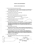
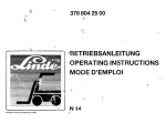
PITMAN SHAFT SECTOR
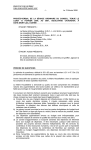
Figure 7-1-Steering Gear Worm and Nut , Showing Ball Circuits
7 -2 DESCRIPTION OF STEERING GEAR
AND TIE RODS
a. Steering Gear Assembly
The steer ing gea r is the recirculat ing ball
worm and nu t t ype. The worm on lower end
of the steering shaft a nd the t all n ut wh ich is
mounted on t he worm have mat ing spiral
grooves in which steel ball s circ ulate to provide a frictionless drive between wo r m and
.
.
.
.
.
( 234 )
Series 70
_
0(
2 Roller Bearings
~
+-- - 1 Ball Be aring
~
+-- - - - -60, %2"- - - - ---+
+0 t o .002 "
--+
+% to 1%
~
0(
2 to 2 ~
~
+--Tighten Plug Solid-----+
+-- -Back Off 2± turns- ---+
+- - -See figure 6-36
)+-- - -1. 1205" to 1.1210"- ~
+-- - - .0035" to .0045"
~
-+--- - 1. 1235" to 1.1240" ~
+--- - .0015 " to .0025 "· - ..---+-
nut. See figure 7-1.
Two sets of 30 ba lls are used, with each set
operating independentlg of the other. The circuit t h rough which each set of ba lls circulates
includes t he grooves in worm and ball nut and
a ball return g uide attached to outer surface of
t he n ut.
When the wheel and steering sh af t turn to
the left the ball nut is moved dow nward by
the balls which roll between the worm and nut.
As the balls reach the outer surface of nut
they enter the r et urn guides which direct them
across a nd down into the ball nut, where they
ent er t he circuit again. When a right turn is
made, the ball n ut moves upward and t he balls
circulate in t he r everse direction. See fig ure
7-1.
Teeth on the ball nut engage t eeth on a
sector forged integral with t he pitman shaft .
The teeth on the ball n ut a re made so that a
"high point" or tighter fit exist s between the
ball nut and pitman shaft secto r teet h when
front wheels are in the st raight -ahea d posit ion. The teeth of sector are slightl y t aper ed
so that a pr oper lash may be obt ained by mov-
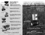
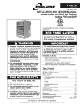
Figu re 7-2 - End Sect io nal Vie w of Stee ring Ge a r
(235)
STEERING GEAR AND TIE RODS
ing the pitman shaft endways by means of an
adjusti ng screw which extends through the
gear housing end cover . The head of adjusting
scr ew and a selectively fitted shim fit snugly
into a T-slot in the end of pitman shaft, so
that the screw also contr ols end play of shaft.
The screw is locked by an ext ernal lock nut.
See figur e 7-2.
The pitman shaft is carried in two bronze
bushings in steering gear housing and one
DESCRIPTION
r
7-3
the steering shaft, transmission cont r ol shaft
and selector control rod. The column jacket is
supported at the lower flange of instrument
panel by a split "pillow-block" type bracket
attached by two bolts. A rubber liner is located between the jacket and the bracket to
eliminate squeaks at this point. The steering
wheel may be set lower than production standard by installing sp ecial spacers between the
instrument panel flange and the column bracket.
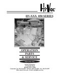
STEERING GEAR
HOUSING
a
IDLER LEVER
BRACK E~
FRAME CLAMPS FOR SIDEW ISE ALIGNMENT
PIVOT BOLT & SLOTTED BOLT HOL ES
FO R VERTICAL A LIGNME N T
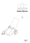
Figure 7-3-Stee rin g Gear to Frame Mounting
bronze bushin g in housing side cover. A springloaded leather sea l in housing prevents leakage of lubricant at oute r end of the shaft. See
figur e 7-2.
The lower end of t he steering shaft is carried by t wo spherical r oller thrust bearings
which bea r against spher ical seats on the ends
of the shaft worm. The outer r ace of the upper
thrust bearing is pressed into the gear housing. The outer race of the lower thrust bearing is formed in the thrust bearing adj uster
which screws into the housing end cover and
is locked by a nut. See figure 7-15. The upper
end of steering shaft is supported by a ball
bearing moun t ed in the direction signal switch
housing on up per end of the st eering gear
column jacket. The upper end of steering shaf t
has a serrated taper seat for t he steering wheel
which is retained by a nut and lock washer.
The steering gear column jacket is bolted to
a flange on steering gear housing, at which
joint a felt seal is located to prevent engine
noise and fumes from passing through jacket
into the car body. The column jacket houses
A bracket on the frame side rail helps to
support the steering gea r housing which is
attached t o bracket and side rail by clamps
and four long bolts. The front lower bolt serves
as a pivot and t he other bolts pass t hrough
slotted holes in t he frame bracket and side
r ail t o provide adjustment for vertical alignment of steering gear assembly. The clamps
bear against the cylindrical extension of gear
housing so that housing can be turned in clamps
to provide for sideways alignment of the assemb ly. See figure 7-3.
b. Steering Tie Rods and Tie Rod Ends
The steering tie rods, which conn ect the pitman arm t o the st eer ing arms on the steering
kn uck les, are direct center point steering type.
The right (long ) tie rod is joined to the left
(short) tie rod and to the pitman arm by ball
stud and spring-loaded bearing connections
which provide free movement in all required
directions without lost motion.
The ball studs riveted on the left (short) tie
rod and the pitman arm seat between pairs of
7-4
TROUBLE DIAGNOSIS
STEERING GEAR AND TIE RODS
ball socket type steel bearings contained in the
left end of the right (long) tie rod. The innermost bearing seats against a washer which
presents lubricant from filling the right end of
tie rod. A bumper of rolled stock, keyed in
place by the lubrication fitting, forms a spacer
and a lubricant reservoir between the two pairs
of bearings. Heavy coil springs on each side
of the pitman arm ball stud bearings and a
threaded plug in the end of tie rod provide
proper pressure between both sets of bearings
r
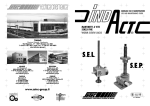
SHORT (LEfT) TIE ROD
(236)
a single screw. The sleeve is locked in place by
a clamp which fits over the slotted end of the
tie rod. During adjustment the tie rod end is
prevented from turning in the sleeve by a large
cotter pin which passes through the shank on
tie rod end into the slots in end of tie rod. See
figure 7-4.
f
7 -3 TROUBLE DIAGNOSIS-STEERING
GEAR AND TIE RODS
This paragraph covers improper steering ac-
LONG (RIGHT! TIE ROD
1
TIE ROD END
DUST COVER
PITMAN ARM
c.c
SECTION
EAR OF CLAMP MUST OVERLAP
SLOT IN TUBE AS SHOWN
-SAME ON RIGHT CLAMP-
Figure 7-4-Tie Rods and Tie Rod Ends
md the ball studs. Flanged bumpers extending
.hrough both springs act as spring guides, pernit a restricted movement of pitman arm ball
stud and bearings as the springs absorb road
ihocks, and prevent the bearings from spreadng and releasing the ball stud in the event of
spring breakage. The spring tension and the
.learances at ends of bumpers are adjusted by
:he threaded tie rod plug.
The openings through which the ball studs
mter the tie rod are protected by pressed steel
lust covers to keep lubricant in and dirt and
vater out. See figure 7-4.
The tie rod end, which connects each tie rod
;0 a steering arm, is a springload ball stud and
locket unit assembly. A rubber dust seal fits
rver the stud where it emerges from the socket,
:0 provide protection against entrance of dirt
md water. The tie rod end screws into a sleeve
.vhich, in turn, screws into the end of each tie
'00. The tie rod sleeve, which provides for
oe-in adjustment, has a right-hand internal
hread and a left-hand external thread so that
me turn of the sleeve is equal to two turns of
tions which are most likely to be caused by the
steering gear assembly or tie rods. Improper
steering actions which are most likely to be
caused by chassis suspension members are covered in paragraph 6-11.
a. Excessive Play or Looseness in Steering
System
(1) Steering gear or tie rods adjusted too
loose or worn (par. 7-5).
(2) Loose pitman arm or loose steering arms.
(3) Front wheel bearings incorrectly adjusted or worn (par. 6-15).
(4) Steering knuckle bushings or king pins
worn (par. 6-16).
b. Hard Steering-Excessive Effort Required
at Steering Wheel
(1) Low or uneven tire pressure (par. 6-8).
(2) Insufficient or improper lubricant in
steering gear or front suspension (par. 1-1 and
1-5) .
(3) Steering gear to frame misalignment
(par. 7-5).
(237)
STEERING GEAR AND TIE RODS
(4) Steering gear or tie rods adjusted too
tight (par. 7-5) .
(5) Front wheel alignment incorrect in one
or more angles (par. 6-31).
(6) Frame bent or broken (par. 9-2).
c. Rattle or Chuckle in Steering Gear
(1) Insufficient or improper lubricant in
steering gear (par. 1-5).
(2) Excessive back lash between ball nut
and pitman shaft sector in straight ahead position or worm thrust bearings adjusted too
loose (par. 7-5). NOTE: On turns a slight rattle may occur, due to the increased lash between ball nut and sector as gear moves off the
center or "high point" position. This is normal
and lash must not be reduced to eliminate this
slight rattle.
(3) Pitman arm loose on shaft.
(4) Excessive looseness in tie rod connections.
(5) Steering gear loose at mounting brackets.
PITMAN SHAFT
ADJUSTING SCREW
~
ADJUSTMENTS
2. Turn steering wheel gently in one direction
until it stops, then turn it back one revolution.
CAUTION: Never turn wheel hard against
stopping point as damage to ball nut assembly
may result.
3. Check for lash between ball nut and pitman shaft by working the pitman arm. If a
perceptible lash does not exist, loosen lock nut
and turn pitman shaft adjusting screw counterclockwise, until lash can be felt when working pitman arm. See figure 7-5. This separates
the worm thrust bearing load from the "high
point" load caused by close meshing of ball nut
and pitman shaft teeth.
4. Turn steering wheel slowly from one extreme position to the other. Wheel should turn
freely and smoothly through entire range.
Roughness indicates faulty worm thrust bearings or brinelled races. Hard pull or binding
indicates misalignment of steering gear assembly in mountings, or an excessively tight
adjustment of worm thrust bearings. Any misalignment must be corrected before steering
gear can be properly adjusted.
5. If binding exists, loosen the four steering
gear to f r ame bolts and the two steering column bracket bolts. Center steering column in
the cutout in dash panel and tighten column
bracket bolts, then tighten the steering gear to
frame bolts. If binding still exists, check the
steering gear column jacket for evidence of
being sprung which is usually indicated by a
rippled or wavy surface, particularly at the
lower end . A sprung jacket will throw the
steering shaft upper bearing out of line with
worm thrust bearings and create side pressure
on steering shaft. NOTE : If steering gear was
Figure 7-5-Steering Gear Adjuotmenls
7 -4 ADJUSTMENT OF STEERING GEAR
AND TIE ROD
IMPORTANT : Never attem pt to adjust steering gear while it is connected to tie rod. Steering gear must be free of all outside load in
order to pro perly adjust worm thrust bearings
and the lash bet ween ball nut and pitman shaft
teeth.
1. Disconnect steering tie rod from pitman
arm by unscre wing t ie rod plug until bearings
will release the ball stud. See figure 7-4. Check
ti ght ness of pitman arm nut with 18" wr ench.
7-5
Figu,e 7-6- Ad lusting Worm Thrust Bearing s
,
7-6
ADJUSTMENTS
STEERING GEAR AND TIE RODS
(238)
out of alignment or jacket is sprung, check body
mounting bolts which may have loosened and
allowed body to shift. Also check the serrations
on pitman shaft; if serrations are twisted, re..
place the shaft.
The pull required to keep wheel moving through
"high point" should be between 2 and 2%,
pounds. Readjust if necessary to remove tight
spots and obtain specified load at wheel rim.
NO'rE: If lash cannot be removed at "high
6. T ight en housing end cover bolts. Loosen
worm thrust bearing adj uster lock nut, using
Wrench J 1592. Turn t h rust bearing adjuster,
using Adjuster Bit KMO 695 and a ratchet
wrench, until a sli ght load is felt when turning
steering wheel near extreme positions, then
tighten lock n ut. See figure 7-6. CAUTION:
point," or if gear load varies greatly and feels
rough, the gear assembly should be removed
for inspection of internal parts (par. 7-8 and
Do not back out adjuster far enough to permit
thrust bearings to get out of line with ends of
worm .
Fig ure 7-7-Ch ecki ng Thruot Bea ring or Lash Adiustment
wi th Sca le
7. When worm thrust bearing adjustment is
.ompleted, check load on bearings by applying
kale J 544-A to a spoke at the rim of steering
"heel and pulling at 90 degrees to spoke, figure
'-7, with wheel turned to near one extreme
iosit ion . The pull required to keep wheel turnng should be between % and llfs pounds. Reidjust to within these limits if necessary.
8. Turn steering wheel from one extreme
iosition to the other while counting the turns,
hen turn wheel back one-half the total number
-f turns. This pla ces steering gear on the "high
ioint" at which no lash should exist between
'all nut and pitman shaft teeth. The lower
poke of wheel should point straight down, or
lot over %" to either side of straight down
osition.
9. Tighten housing side cover bolts. Loosen
rck nut and turn pitman shaft adj ust ing scr ew
lock wise until lash between ball nut and p itran shaft teeth is just removed. Work pitman
.r rn back and forth to feel for lash. After tightning adjusting screw lock nut, rotate steering
Theel back and forth through the "high point"
ange and check for tight spots. Check pull at
Theel with Scale J 544-A as described above.
7-9).
10. Connect steering tie rod to pitman arm,
being careful to properly seat the bearings
around ball stud. Make sure that the pressed
steel dust cover properly covers opening around
ball stud. See figure 7-4. Turn the tie rod plug
up solid then back off two turns and install
cotter pin.
11. Road test car for ease of steering. If
steer ing gear was adjusted to specified load
limits and hard steering exists, the front suspension members should be checked for lubrication and alignment and tire inflation pressures should be checked. When car is moving
straight ahead, the lower spoke of steering
wheel should be straight down, or not over %"
to either side of straight down position. If
lower spoke is too far to either side, check
steering wheel for proper position on steering
shaft (par. 7-6) and check tie rods for equal
adjustment and toe-in (par. 6-30). It is important to have the steering gear in the no-lash
range when car is moving straight forward.
7 -5 ADJUSTM EN T OF STEERING WHEEL
HEIGH T
a. 1948 Models
On 1948 Models, the steering wheel cannot be
r aised from the production setting but it can be
lowered approximately 11;16" by installation of
two special spacers between the steering column
bracket and the lower flange of instrument
panel, and using longer bracket bolts.
Two column bracket spacers, 14" thick, and
t hree bracket bolts of different lengths are included in the spacer package listed under Group
6.764. Figure 7-8 shows the proper len gth of
bolt to use on the right and left side of bracket
for each model.
b. 1949 Model s
On 1949 Models, the steering wheels on Series
50-70 can be raised from the production setting; however, the increased height may affect
visibility for the average driver. The Series 70
steering wheel can also be lowered from the
production setting.
' 13 2 5 0 13
WHEEL REPLACEMENT
STEERING GEAR AND TIE RODS
(239)
4 t{" LONG -
- --
steering column to prevent hom from blowing.
2.. On solid spoke steering wheel, carefully
pry out the hom button cap. On flexible steering wheel, pry off the monogram .and bezel
assembly, then remove the horn button operating wheel which is attached by three screws.
-
LEFT SIDE 140·50/ - -- --
13 23 016
4 1~"LONG
RIGHT SIDE
-
-
-
7-7
-.,
t4o--.55'0\
~====j,
LEFT SIDE (7 0t-
11"
5TEERING WHEEL LOWERED iii
WITH TWO SPACERS (I3212S3 )
NUT BACKED OFF
Figure 7-8-lnltall ation of Steering Column Bracket Spacers
and Boltl-·1948 Mode'"
The Series 50 steering wheel can be raised
approximately lYt6" by substituting the Series
70 steering column bracket and spacers, and
the Series 70 steering column to instrument
panel grommet.
The Series 70 steering wheel can be raised
approximately Y2" by removing the two 0/16"
spacers located between the steering column
bracket and the instrument panel. This may
cause some buckling of the steering column to
instrument panel grommet.
The Series 70 steering wheel can be lowered
approximately lYt6" by substituting the Series
50 steering column bracket, bracket bolts, and
steering column to instrument panel grommet.
c. Adjustment Procedure
When the steering wheel is changed in height
it is necessary to loosen the four steering gear
to frame bolts. The dash insulation retainer
must be disconnected from the toe panel. Center
the steering column in the cutout in dash panel
and tighten the column bracket bolts before
tightening the four steering gear to frame
bolts, to make sure that steering column is not
held in a sp ring position. Before attaching the
dash insulation r etai ner t o t oe panel, pack t he
opening around column with a piece of jute
filler to prevent fumes from entering the body.
7 -6 STEERING WHEEL REPLACEMENT
a. Removal of Steering Wheel
1. Disconnect wire at hom cable connector on
Figure 7 -9-Removing Steering Whee' with Puller J 1S66
3. Set direction signal switch in "off" position to avoid possible damage to switch operating mechanism.
4. Flatten the tab of lock washer, then back
off steering wheel nut several turns but do not
remove nut. Apply Puller J 1566 and adapter
(fig. 7-9) and pull wheel back to nut. NOTE:
If wheel hub is v er y tight on shaft, apply a
moderate strain with puller then tap end of
puller screw to break hub loose from shaft
without distorting wheel hub. Remove puller,
nut, and lock washer, then remove steering
wheel.
b. Replacement of Signal Switch Cam
When a steering wheel is being replaced it is
necessary to remove the direction signal switch
cam from the old wheel and install it on new
wheel. The cam, spring washer and bronze
washers may be removed from hub of steering
wheel by removing the snap ring. Install cam
and washers as described in paragraph 10-64.
c. Installation of Steering Wheel
Befo re in st allin g steering w heel, set signal
switch tn "o ff" position to prevent the cam from
st riking the swit ch trigger and damaging the
switch operating mechanism.
Location marks for proper installation of
steering wheel on steering shaft are provided to
ensure a vertical position of the steering wheel
lower spoke when front wheels are in straightahead position. The upper end of steering shaft
7-8
BEARING REPLACEMENT
STEERING GEAR AND TIE RODS
(240)
has a small location notch, t he flexible wheel
has a small drilled location hole near the center
and in line with the lower spoke, and the solid
spoke wheel has a location mark on the underside of the lower spoke. These location marks
on shaft and wheel must be in line when wheel
is installed. See figur e 7-10.
SW ITCH
HOUSING
BOARD
~
-
Figure 7-11 -Installing Control Shaft Bearing In Signal
Switch Housing
Figure 7-1 O-Location Marks on Steering Shaft and Flexible
Steering Wheel
With wheel installed, install lockwasher and
st eer ing wh eel nut, tighten nut securely, then
bend one tab of lockwa sh er up against a flat on
nut . Install horn button oper at ing wheel and
monogram a nd bezel assembl y, on flexible steering wh eel. The crest must be right sid e up with
wheel in str aight-ahead position. Connect wire
to horn cable connect or on steering column,
then adjust timing of direction signal switch
earn as described in paragraph 10-63.
7 -7 REPLACEMENT OF BEARINGS IN
SIGNAL SWITCH HOUSING
a . Replacement of Transmission Control
Shaft Upper Bearing
1. Disco nnect direct ion signal switch wires
from termi nals on instrument panel.
2. Remove steering whe el (pa r. 7-6) . Remove
steering shaft upp er bea ring spri ng a nd spri ng
seat.
3. Remove sign al switc h housing from steering colum n jacket, pulling switch wires up fa r
enoug h to permit working on underside of
switch housing.
4. Pry out old cont rol sh aft bearing, which
will allow the control lever hou sing thrust
wash er, plain washer and spr ing washer to
be removed for inspection. Replace thrust or
spring washer if worn.
S. Support t he signal switch housing on a
board held on the knees while installing the
spring washer, plain washer, and thrust washer
in the order named. Drive the new control shaft
bearing into housing, using Replacer J 1585.
See figure 7-11. CAUTION: Use care to avoid
scoring this fabric bearing , which would cause
hard shifting of gears.
6. Install signal switch housing on column
jacket, connect signal switch wires to terminals
on instrument panel, install spring seat and
spring, and install steering wheel according to
location marks (par. 7-6).
b. Replacement of Steering Shaft Bearing
1. Disconnect signal swit ch wires from terminals on instrument panel.
2. Remove st eer ing wh eel (par. 7-6). Remove
steer ing sh aft upper bea ring spr ing and sprin g
seat .
3. Rem ove signa l switch housing f r om st eering column jacket, pulling swit ch wir es up far
enough to permit working on underside of
switch housing.
4. Drive old st eeri ng shaft bearing fr om
swit ch hou sing, then drive new bear ing into
housing while suppor t ing the housing on a
board held on the knees. Drive only against
oute r race of bea r ing. NOTE : Bearing can also
be installed afie» installation of switch hou sing
on colum n jacket, if pre ferred.
5. In stall sign al switch housing on column
jacket , conn ect signal switch wires to terminals
on inst r ument panel, install spr ing seat and
spring, a nd install steering wheel according to
locat ion ma rks (par. 7-6) .
(241)
STEERING GEAR AND TIE RODS
REMOVAL AND DISASSEMBLY
7-8 REMOVAL OF STEERING GEAR
ASSEMBLY
1. Disconnect the pitman arm from the steering tie rod by unscrewing tie rod plug until
bearings will release the ball stud.
2. On Series 70 only , remove air cleaner assembly. Disconnect fuel and vacuum pipes from
carburetor and carefully move them out of the
way. .
3. Remove windshield washer and bracket, if
installed on car.
4. Disconnect transmission selector rod from
selector control lever and unhook anti-rattle
spring. Disconnect upper shift rod from control
shaft lower lever. Disconnect clutch linkage
anti-rattle spring from the shift idler lever pin.
5. Disconnect wires from horn cable connector, back up light switch, and neutral safety
switch. (Dynaflow cars only.) Pull speedometer
cable from clip and then remove horn cable connector from column jacket to avoid damage
during removal of gear assembly.
6. Disconnect one end of cross brace at cutout in cowl and swing brace to one side .
7. Remove dash insulator retainer and steering column pad. Pull back the floor mat and remove pedal plate attached to toe panel.
8. Remove steering wheel (par. 7-6) and the
upper bearing spring and spring seat. Remove
gear shift control lever and signal switch control lever. Remove front seat cushion.
9. Disconnect direction signal switch wires
from terminals on instrument panel.
10. Remove steering column bracket. On 1949
models remove the steering column to instrument panel grommet.
11. Remove the steering gear to frame bolts
and clamps and carefully support the steering
7-9
Figure 7-12-Removing Pitman Arm w ith Puller J 1596
column to avoid damaging column jacket. Move
gear assembly to rear as far as possible, turn
assembly over so that pitman arm is uppermost,
then lift forward end up between engine and
fender and move forward to remove gear assembly from car. It is advisable to have a helper
guide the column jacket and signal switch
housing through the cutout in cowl panel to "
avoid damaging the finish of these parts.
7-9 DISASSEMBLY, CLEANING AND
INSPECTION OF STEERING GEAR
a. Disassembly of Steering Gear
1. Remove nut, lock washer, and pitman arm
using Puller J 1596 to remove pitman arm; the
gear assembly will be damaged if arm is driven
or pried off pitman shaft. See figure 7-12.
2. Remove direction signal switch housing
from column jacket and leave hanging by
wiring. Remove control lever housing shield,
W O RM BEARIN G
STEERING GEAR
"<,
HOUSING
ADJUSTER LOCK N7 T
'~A"""--~
rENO COVER
\:STEERING SHAfT
[~ " X GASKET
"
fi \",
,.
/
PITMAN SHAfT--.;:c-
-
_
~~
- GASKET
,
..
~ SHIM
SIDE COVER
,vI
I,
LOCK
NUT-~""''' --AOJUSTING
Figure 7 -13 -Steering Gear Assembly-Exploded View
SCREW
.
7-10
REMOVAL AND DISASSEMBLY
loosen control lever housing clamp bolt by inserting screwdriver through slot in jacket, then
slide housing from transmission control shaft.
Remove housing lower thrust and plain washers.
3. Remove back-up light switch. Remove
neutral safety switch and shift control detent,
on Dynaflow cars only. Remove steering column
jacket and seal from gear housing.
4. Remove control rod and control shaft from
jacket if inspection of these parts is desired.
Pull signal switch wires through slot in jacket
and remove switch housing assembly from
jacket.
5. Loosen adjusting screw lock nut, then re move housing side cover with pitman shaft
attached. Remove gasket. Separate pitman
shaft from side cover by unscrewing the adjusting screw. (See figure 7-13.)
6. Loosen lock nut and back off worm thrust
bearing adjuster several turns, then remove
housing end cover and gasket. Remove lower
thrust bearing, steering shaft, and upp er bearing from housing.
7. Remove ball return guide clamps and
guides from ball nut, t urn ball nut over to remove balls , then remove ball nut from steering
shaft worm.
b. Cleaning and Inspe ction of Steering
Gear Pa rts
1. Clean and inspect all ball and roller bearings and races, including race in housing, as
described under Bearing Service (par. 1-13,
1-14) .
2. Thoroughly clean all other pa rts in clean
kerosene or other solvent and wi pe dry with
clean cloths. Do not clean signal switch housing
assembly with solvent as switch and wiring will
be damaged.
3. Inspect pitman shaft bushings in gear
housing and end cover. Rep lace bushings in
housing and replace end cover if bushings are
worn excessively.
4. It is advisable to replace t he pitman shaft
grease seal in housing to avoid possible leakage
of lubricant. The seal must be installed with
feather edge toward inside of housing.
5. Inspect oil shedder and control shaft
bearing in gear housing. If bearing is of doubtfu l conditi on r eplace it, using Remover J 1583
to remove old bearing and Replacer J 1587 t o
install new bearing. See figures 7-14 and 7-15.
Use care when installing new bearing as har d
gear shifting will result if this bearing is
damaged.
STEERING GEAR AND TIE RODS
(242)
Figure 7-14-Removing Control Shaft Lower Bearing
6. Inspect steering shaft for wear or brinelling in ball and roller bearing races, which would
r equir e replacement of shaft; check shaft to
make sure it is straight.
7. Inspect teeth of ball nut and pitman shaft.
If scored or excessively worn it is advisable t o
replace both parts to ensure W'0per mating of
teeth. Check serrations of pitman shaft; if
twisted, replace the shaft.
8. Check fit of pitman shaft adjusting screw
and shim in the slot in end of pitman shaft.
With shim in place, screw head must be free to
turn in slot with no perceptible end play to
.002" loose. If end play is excessive, selectively
fit a new shim; these are furnished in four
different thicknesses.
9. Inspect steering colum n jacket for distor-
REPLACER J 1587
Figure 7- I S- Insta lli ng Control Sha ft Lower Bearing
(2 43)
STEERING GEAR AND TIE RODS
tion. A rippled or wavy feeling of jacket surface, particularly at lower end , will usually indicate a sprung jacket. Replace jacket if sprung
or otherwise damaged.
10. Inspect control shaft upper bearing, control lever housing thrust washer, and steering
shaft upper bearing in signal switch housing.
Replace unserviceable parts as described in
paragraph 7-7.
7-1 0 ASSEMBLY AND INSTALLATION
OF STEERIN G GEAR
a. Assembly of Steering Gear
To assemble the steering gear, reverse the
sequence of steps given for disassembly in
paragraph 7-9. In addition, observe the following inst r uct ions that apply to assembly:
1. Lubricate bearings and gear s with specified steering gear lubricant (par. 1-5) at time
of assembly .
2. Use all new gaskets to avoid oil leaks.
3. When assembling ball nut on worm be sure
to place 30 balls in each circuit, making a total
of 60 balls.
4. When installing pitman shaft be careful to
avoid damaging or turning the feather edge of
the leather grease seal in gear housing.
5. When ins erting transmission control shaft
in lower bearing, and when installing signal
switch housing on jacket, use care to avoid
scoring the fabric in control shaft bearings.
Scored bearings will cause hard shifting of
t ransmission gears.
6. The control lever housi ng shield is wid er
on one side of hole and this sid e must be placed
below control lever .
7. Install pitman arm on shaft so that arm is
parallel with st eering column when gear is in
straight ahead or no-lash position .
8. Temporarily install steering wheel and
ad j ust worm shaft thrust bearings for proper
load an d pitman shaft for proper gear lash as
descri bed in paragraph 7-4. Remove wheel.
ASSEMBLY AND INSTALLATION
7-11
b. Installation of Steering Gear
Install steering gear assembly by reversing
sequence for removal. During installation the
following instructions must be observed :
1. Leave frame bracket bolts loose until
steering column bracket is installed. Center
steering column in cutout in dash panel and
tighten the column bracket bolts, then tighten
the frame bracket bolts.
2. Connect signal switch wires to terminals
on instrument panel.
3. Before installing gear shift control lever,
coat inner end and the socket in selector rod
with Lubriplate. If a new bearing is being inst all ed on control lever, the large diameter of
bearing must be toward the lever knob. During
installation of lever be careful t o draw housing
nut tight so that shoulder in nut will bear
against flange of bearing seat and lock the seat
in place.
4. Install steering wheel with location marks
in line (par. 7-6).
5. On car equipped w ith Syncro-Mesh transmission, che ck adjustment of transmission controls as described in paragraph 4-25, when connecting shift rod to control shaft lower lever.
5a. On car equipped with Dyna/lo w Drive,
check transmission control linkage as described
under "Service Adjustments" in the 1948 Buick
Dynaftow Transmission Service Manual. Check
sett ing of neutral safety switch as described in
paragraph 10-34.
6. When connecting tie rod to pitman arm
be careful to properly seat the bearings around
the ball stud and make sure that the pressed
steel dust cover properly covers opening around
ball stud. Turn tie rod plug up solid then back
off two turns and install cotter pin .
7. Fill steering gear housing with specified
lubricant (par. 1-5) .
8. Check adjust ment of back-up light switch
as described in paragraph 11-10.
9. Road test car f or ease of steeri ng a s descr ibed in pa ragr ap h 7-4, step 11.
, -12
MODELS 56-C
1948- 1949 BUICK SHOP M AN UAL
1948 Model 56-C
1949 Model 56·C
(244)