1
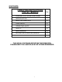
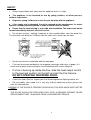
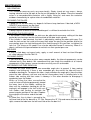
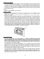
WOOD FIRE
OWNERS MANUAL
WARNING: Improper installation, adjustment, alteration, service or maintenance can cause injury or property
damage. For assistance or additional information consult an authorized technician, or your Masport Wood
Fire Dealer.
FOR YOUR SAFETY: Do not store or use gasoline or other flammable vapors and liquids in the vicinity of
this appliance. Installation and service must be performed by authorized personnel.
PLEASE KEEP THESE INSTRUCTIONS FOR FURTHER REFERENCE.
Manufactured in New Zealand by:
GLEN DIMPLEX AUSTRALASIA LIMITED
38 Harris Road, East Tamaki, Auckland
Ph: 0800 666 2824
Fax: 09 274 8472
Email: [email protected]
Web: www.glendimplex.co.nz
Distributed in Australia by:
GLEN DIMPLEX AUSTRALIA PTY LIMITED
Unit 2, 205 Abbotts Road, Dandenong South, Victoria 3175
Ph: 1 300 566 816
Fax: 1 800 058 900
Email: [email protected]
Web: www.glendimplex.com.au
Part No.593286
CONTENTS OF LOOSE PARTS BAG (Some freestanding models)
(Note: You may not need all these parts for your installation)
Part No.
Quantity
522117
10
M6 Hexagon Nut
523031
4
M6 Flat Washer
Where Used
4 - Pedestal front to pedestal sides
4 - Firebox to pedestal
2 - ‘L’ Brackets to pedestal
4 - Firebox to pedestal
521060
4
M6 x 35mm Hex. Set Screw
4 - Firebox to pedestal
521075
6
M6 x 12mm Hex. Set Screw
521605
4
521635
4
522402
2
521637
2
Self Threading Screw
— 25mm long
2 - Seismic restraint bar to pedestal
986413
2
‘L’ Bracket
2 - Sides or rear of pedestal
6mm
Description
4 - Pedestal front to pedestal
sides
2 - ‘L’ Brackets to pedestal
4 - Heat shield to top of pedestal
Self Threading Screw
— 12mm long, zinc plated
finish
Self Threading Screw
4 - Pedestal rear panel to pedestal
— 12mm long, black
finish
‘C’ Nut (Spire # SNU 0537)
12mm
2 - Seismic restraint bar to pedestal
25mm
35mm
2
CONTENTS
OPERATING INSTRUCTIONS
FOR ALL MODELS
Page
CONTENTS OF LOOSE PARTS BAG
2
INTRODUCTION
4
BASIC INFORMATION
5
LIGHTING UP
6
OPERATING HINTS
7
SAFETY
8
9,10,11
MAINTENANCE
BEFORE EACH HEATING SEASON
12
THIS BOOK CONTAINS IMPORTANT INFORMATION.
PLEASE KEEP IT IN A SAFE PLACE FOR FUTURE REFERENCE.
3
INTRODUCTION
In the interests of your safety, most building regulatory Authorities in Australia and
New Zealand require any wood fire installation to comply with Installation Standard
AS/NZS 2918. They may also have local requirements in addition to those in the
Standard. Check with your local Building Authority before commencing
installation, to find if you will require a Permit and whether there are extra
requirements. All MASPORT Wood fires have been tested to ensure that they will
meet the appropriate safety Standard requirements if the instructions in this book are
followed. As the safety and emissions performance can be affected by altering the
appliance, no modifications are allowed without written permission from the
manufacturer.
Wood fire models covered by this manual have been tested to demonstrate compliance
with current general emission requirements in Australia and New Zealand, but some
areas have stricter limits. Only some of the models meet those limits, so check before
purchasing or installing a particular model.
In areas covered by stricter emission regulations:(I) If a water-heating device is permitted, it must be factory fitted or be a Masport
accessory retrofitted strictly in accordance with the instructions supplied by Masport.
(II) Coal must not be used as a fuel.
(III) Wood fuel must have a moisture content of less than 25%.
WE RECOMMEND TH AT THE INSTALL ATION OF YOUR M ASPORT WOODFIRE
BE CARRIED OUT BY A QUALIFIED SPECIALIST INSTALLER.
IF ANY ELECTRICAL WORK IS REQUIRED, IT MUST BE CARRIED OUT BY A LICENSED
ELECTRICIAN.
WARNING: THE APPLIANCE AND FLUE SYSTEM MUST BE INSTALLED IN ACCORDANCE
WITH AS/NZS 2918 AND THE APPROPRIATE REQUIREMENTS OF THE RELEVANT
BUILDING CODE OR CODES.
WARNING: APPLIANCES INSTALLED IN ACCORDANCE WITH THIS STANDARD SHALL
COMPLY WITH THE REQUIREMENTS OF AS/NZS 4013 WHERE REQUIRED BY THE
REGULATORY AUTHORITY, I.E. THE APPLIANCE SHALL BE IDENTIFIABLE BY A
COMPLIANCE PLATE WITH THE MARKING ‘TESTED TO AS/NZS 4013’. ANY
MODIFICATION OF THE APPLIANCE THAT HAS NOT BEEN APPROVED IN WRITNG BY
THE TESTING AUTHORITY IS CONSIDERED TO BE IN BREACH OF THE APPROVAL
GRANTED FOR COMPLIANCE WITH AS/NZS 4013.
WARNING FOR APPLIANCES WITH WATER HEATING DEVICES: DO NOT CONNECT TO AN
UNVENTED HOT WATER SYSTEM. INSTALL IN ACCORDANCE WITH AS 3500.4.1 OR NZS
4603 AND THE APPROPRIATE REQUIREMENTS OF THE RELEVANT BUILDING CODE OR
CODES.
IN SOME REGIONS POWER POINTS ARE NOT PERMISSIBLE WITHIN THE FLOOR
PROTECTOR AREA, PLEASE CHECK WITH YOUR LOCAL AUTHORITY.
PLEASE ENSURE THAT ONLY COMPONENTS APPROVED BY MASPORT ARE USED FOR
THE INSTALLATION, as substitutes may adversely affect performance and might nullify
compliance with the requirements of AS/NZS 2918.
CAUTION: MIXING OF APPLIANCE OR FLUE SYSTEM COMPONENTS FROM DIFFERENT
SOURCES OR MODIFYING THE DIMENSIONAL SPECIFICATION OF COMPONENTS MAY
RESULT IN HAZARDOUS CONDITIONS. WHERE SUCH ACTION IS CONSIDERED, THE
MANUFACTURER SHOULD BE CONSULTED IN THE FIRST INSTANCE.
CAUTION: CRACKED AND BROKEN COMPONENTS, e.g. GLASS PANELS, MAY
RENDER THE INSTALLATION UNSAFE.
TO AVOID THE RISK OF ELECTRIC SHOCK OR CONTACT WITH MOVING PARTS, ONLY
THE MANUFACTURER, THE MANUFACTURER’S SERVICE AGENTS OR SIMILARLY
QUALIFIED PERSONS SHOULD REMOVE THE BOTTOM PANELS WHICH ALLOW
ACCESS TO FANS.
4
OPERATING INSTRUCTIONS — ALL MODELS
BASIC INFORMATION
DOOR HANDLE
Front mounted handles.
To open the door:- Rotate the handle upward anti-clockwise to the 1 o’clock position.
To close the door:- Push the door toward the fire box, using the handle, and turn the
handle clockwise to the 4 or 5 o’clock position.
Side mounted handles.
To open the door:- Pull the lower part of the handle, forward and upward.
To close the door:- Hold the handle up whilst closing the door. Push the handle down
to the vertical position to lock the door.
HEAT OUTPUT CONTROL
This control has a sliding action. It is clearly marked with a wedge shaped symbol. Slide
the control in the direction of the wide end of the wedge (to the right) to increase the
heat output and toward the narrow end (to the left) to decrease it. Shutting a high fire
down rapidly by starving it of air will result in undesirable emissions. For this reason,
Masport wood fires are designed to settle down to lower heat outputs comparatively
slowly.
Note:- The lever on some models is marked ‘H’ for high fire and ‘L’ for low fire.
EXTENDED BURNING
Masport Fires will burn for a long period. To achieve this, level the embers and load
the fire wood lying front to back. Use large logs and ensure that there are gaps
between the fire wood to allow air to reach all the pieces of wood. Open the air inlet
fully for 15 to 20 minutes. When the fire is burning fiercely, reduce the air intake in
stages to the minimum opening. NEVER LET THE FIRE SMOULDER.
FAN OPERATION
Inbuilt Wood fires should not be operated on maximum heat with very dry softwood,
unless the fan is operating.
On freestanding woodfires, the optional fan MUST only be operated when the air
control on the fire, is set on ‘HIGH’
ESSENTIAL ADVICE
Correct installation, the use of only DRY wood and adherence to the following
instructions will ensure satisfactory performance.
WARNING: MAKE SURE THE MINIMUM HEATER-TO-WALL DISTANCES SHOWN ON
THE SPECIFICATION SHEET, ARE ALWAYS MAINTAINED BETWEEN THE HEATER
AND ANY HEAT SENSITIVE ITEMS. (FURNITURE, DRAPES, ETC.)
WARNING: DO NOT STORE FUEL WITHIN THE HEATER INSTALLATION CLEARANCES.
WARNING: DO NOT USE FLAMMABLE LIQUIDS OR AEROSOLS OR PLACE THESE IN THE
VICINITY OF THIS APPLIANCE WHEN IT IS OPERATING.
WARNING: THIS APPLIANCE MUST NOT BE USED AS AN OPEN FIRE.
WARNING: WHEN FITTED WITH A WATER HEATING BOOSTER, THIS APPLIANCE MUST
NOT BE CONNECTED TO AN UNVENTED HOT WATER SYSTEM. THIS APPLIANCE
MUST BE INSTALLED WITH AN OPEN VENT. THERE MUST BE NO SHUT-OFF OR NONRETURN VALVES IN THE PIPING SYSTEM. REFER TO WATER PIPE INSTALLATION
INSTRUCTIONS.
5
LIGHTING UP
CAUTION: THIS APPLIANCE SHOULD BE MAINTAINED AND OPERATED AT ALL
TIMES IN ACCORDANCE WITH THESE INSTRUCTIONS
Slide the heat output control fully to the hot position.
Crumple up several double sheets of newspaper and place them in the centre of the
firebox. Build a pyramid of thin, dry kindling wood on the paper with some heavier
pieces on top. Light the paper at the bottom and leave the door slightly ajar until the
kindling has ‘caught’, then latch the door shut firmly.
When loading fuel, place the pieces of wood in a front-to-back direction to ensure good
air access and the cleanest possible burning
Always leave ash to the level of the tops of the floor ribs.
WARNING: DO NOT USE FLAMMABLE LIQUIDS OR AEROSOLS TO START OR
REKINDLE THE FIRE.
WARNING: ALWAYS MOVE THE AIR CONTROL TO THE OPEN POSITION (TO THE RIGHT)
BEFORE OPENING THE FIRING DOOR.
When the kindling is well alight, open the door slowly and add some larger pieces of
wood. Do not throw fuel pieces into the firebox as this may damage the
top baffle and the insulating boards or firebricks.
Close and latch the door firmly.
Move the heat output control away from the maximum position only after the fire is well
established. A new wood fire should not be run at higher than half setting beyond the
first 30 minutes until it has been used for a total of 8 hours. Once fully ‘run in’, we
recommend running at full heat for up to one hour after lighting as this will minimize
creosote build-up in the flue. The control can then be set wherever desired.
The special high temperature paint on the firebox will emit some smoke as it cures
during the first hour or so of running. This is quite normal.
CAUTION: THIS APPLIANCE MUST NOT BE OPERATED WITH A CRACKED GLASS.
6
OPERATING HINTS FOR CLEAN BURNING AND BEST EFFICIENCY
FUEL: USE ONLY WOOD THAT HAS BEEN AIR DRIED IN A SHELTERED WELL
VENTILATED STACK, PREFERABLY FOR AT LEAST 12 MONTHS. If moist fuel
must be used, add it only to a really hot fire, mixing it with a large proportion of dry
fuel. In Clean Air Zones, only wood may be used as fuel, and it must have a moisture
content not greater than 25% (measured on a dry weight basis).
•
Do not burn driftwood or coloured paper as these can corrode the wood fire and
flue.
CAUTION: THE USE OF SOME TYPES OF PRESERVATIVE TREATED WOOD AS
FUEL CAN BE HAZARDOUS.
• Add fuel reasonably often. A large fuel load placed on a dying fire can drop
combustion temperatures undesirably.
• Avoid large smouldering fires. A small intense fire is more efficient.
• Move the heat control to maximum for a minute or so and turn off the air circulating
fan (if fitted) before opening the door on a low burning fire. This will clear away any
fumes in the firebox.
• Always open the door SLOWLY, and close and latch it shut securely again as soon
as possible after re-loading.
• When loading fuel, place the pieces of wood in a front-to-back direction to ensure
good air access and the cleanest possible burning.
• Load fuel carefully to avoid damage to the insulating boards, firebricks
or top baffle.
• If smoke wafts into the room from a fully established fire while the door is open, first
check that make-up air can flow freely into the room to replace the air passing up the
flue. (See box below).
Then check that the flue is not obstructed in any way, particularly by the rain cap
being too close to the end of the flue. (See the flue cleaning requirements in the
Maintenance section, page 9). If these checks do not uncover the fault, add an extra
length of flue (bracing it, if necessary) to counteract the down draught effects caused by
roof shape, nearby buildings, hills or trees.
•
Switch off the circulating fan (if fitted) when the fire is burning at low heat outputs.
• Adjust the door to eliminate any minor leakage. (See MAINTENANCE - page 9).
Serious leakage will require a new door seal.
REMEMBER, FOR THE FIRE TO DRAW PROPERLY, AIR MUST BE ABLE TO ENTER
THE ROOM WHERE YOUR WOODFIRE IS INSTALLED. YOU MAY HAVE TO LEAVE
A DOOR SLIGHTLY OPEN AND PERHAPS A WINDOW ELSEWHERE IN THE
HOUSE IF YOUR HOME IS OF MODERN AIRTIGHT CONSTRUCTION. THIS IS
PARTICULARLY IMPORTANT IF AN AIR EXTRACTION FAN IS OPERATING
SOMEW HERE IN THE HOUSE. LEAVING THE ROOM DOOR OPEN WILL HELP
SPREAD WARMTH THROUGH THE REST OF YOUR HOME.
7
SAFETY
•
Always keep children well away from the wood fire when it is alight.
• The appliance is not intended for use by young children, or infirm persons,
without supervision.
•
Supervise young children to ensure they do not play with the appliance.
• If the supply cord is damaged, it must be replaced by the manufacturer, its service
agent or a suitably qualified person in order to avoid electrical hazard.
• Ensure that the electrical plug is accessible after installation. The heater must not be
located immediately below an electrical socket.
• Do not put furniture, clothing, firewood, or other combustibles near the wood fire.
The minimum safe distance is 420mm from the sides and 1 metre from the front.
•
•
Do not leave the fire unattended with the door open.
Fires can be caused accidentally, by wrapping seemingly cold ashes in paper. It is
much safer to place ashes outside in a metal container with a close fitting lid.
•
If a fire is burning up inside the flue, slide the heat output control
to the low heat position (to the left) and call the Fire Service.
DO NOT OPEN THE WOODFIRE DOOR.
•
If you have had a flue fire, inspect your flue for damage before lighting another fire.
•
Do not modify your wood fire in any way without obtaining written permission
from the Manufacturer.
CAUTION. IF THE GLASS IS CRACKED OR BROKEN, THIS APPLIANCE MUST NOT BE
USED.
THE GLASS SHOULD BE REPLACED ONLY WITH A GENUINE CERAMIC GLASS
REPLACEMENT PART, AVAILABLE FROM YOUR MASPORT DEALER.
8
MAINTENANCE
ASH REMOVAL
This should be necessary only very occasionally. Simply shovel out any excess, always
leaving a bed of ash to the tops of the ribs on the bottom of the firebox. Place the removed
ashes in a noncombustible container with a tightly fitting lid, and move the container
outdoors immediately to a place clear of combustible materials.
CLEANING THE GLASS
A good hot fire will burn away any deposits left from a long slow burn. If desired, a NONCAUSTIC oven cleaner can be used.
CLEANING THE CABINET OR FASCIA
A damp rag with a touch of household detergent is sufficient to maintain the finish.
ADJUSTING THE DOOR LATCH
If the handle is front mounted, the latch can be adjusted to overcome settling of the door
gasket by transferring a washer to the outside of the door catch spindle.
If the handle is side mounted, the latch is adjusted by rotating the door catch peg. First
undo the lock-nut on the inside of the peg, then rotate the peg to the position where the
cam portion gives the right locking pressure. Hold the peg in this position, re-tighten the
lock nut. The hinge on all models can also be adjusted inward if necessary. Move it in
about a millimetre at top and bottom to maintain an even gasket pressure.
AIR SLIDE
If the air slide does not move freely, apply a small amount of heat resistant Masport
air slide lubricant, Part No 794113.
CLEANING INSIDE
If you wish to clean the flue or clear away creosote debris, the internal components can be
removed easily (See below). We recommend that you check the condition of all internal
components at least once a season to make sure they are still serviceable.
SECONDARY AIR TUBE REMOVAL
The tube will have either one or two removable angle pins to prevent it from moving
endways and falling out. If there is one removable pin, one end of the tube will have a
welded-on locating pin. To remove the tube, simply withdraw the angle pin(s) from the tube,
move the tube sideways until one end can be swung down from its locating hole in the
firebox side casting and then move it sideways in the other direction to disengage it
completely from the firebox.
W hen re-fitting the tube, ensure that the
small air holes will discharge generally toward
the lower front of the firebox, rotating the
tube until the welded-on locating pin (or the
angle pin) will engage in the slot in the cast
iron firebox side casting to maintain the
correct angular position of the tube. Replace
the angle pin at the other end of the tube.
NOTE:In some fires, the air tube is secured to the
left hand side of the fire box with a “R” Clip. Remove the “R” Clip and move the tube to the
right, remove the tube from the left hand side of the fire box first.
9
FIREBOX TOP BAFFLE.
The special top baffle material operates at very high temperature to ensure clean burning.
Take care not to knock and damage it. For flue cleaning or baffle replacement the
secondary air tube must first be removed as described above. When replacing the baffle,
ensure that it is sitting on top of the supporting shelf at each end and that it is pushed right
to the back until the front corners drop behind the small retainer ribs on the shelves. Re-fit
the secondary air tube.
NOTE:Some fires are equipped with steel baffles.
FIREBOX LINERS
While the insulating boards or firebricks are durable, they will eventually require
replacement. A cracked liner does not require replacing unless it will no longer stay in
position in the firebox.
All Masport models have either fire-bricks, or insulating board to line the firebox. (Some
models have insulating boards already fixed in position at the factory). In some models, two
of the bricks or boards fit across the back of the firebox wall, and the others fit against
the side walls. No force should be required to fit them, and they can be removed, if desired,
for flue cleaning. However, they MUST be in place, and in good condition, before lighting
the fire. Each brick or board is fitted in the same way. Angle it into position, with its top
corner behind the upper retaining lug, then swing it until it is parallel to the wall with its
bottom corner behind the lower retaining lug. Lower the brick or board into position. In
some models there are two boards at the rear and at each side. In that case, fit the metal
retaining channel over the top edges of these pairs of bricks or boards to hold them in
line. The wider leg of the channel goes next to the fire box wall.
FAN MAINTENANCE
Only the manufacturer, its service agent or a similarly qualified person should
remove the bottom grille of the Grande Provincial or the ash shelf of the LE4000, LE
5000, LE 7000, Provincial to carry out fan installation, servicing and maintenance.
The fan should need little attention other than occasionally (perhaps once a year) removing
it to clean dust and lint from the impeller.
First unplug the mains lead from the power point. Fans on in-built fires can be accessed by
lifting off the ash shelf. Fans on free-standing fires are reached by removing the rear of the
pedestal. On free-standing models with internally switched fans, first gently ease off the
speed control knob, taking care to pull it off squarely. Remove the four screws (two on
the Grandview) which hold the fan box in position.
If the fan on the free-stander is internally switched, move it slightly away from the switch
end and withdraw it completely. Some fans simply stand on rubber bushes fitted over
fixed posts. These simply lift away vertically from the post (remove any shipping nuts first,
but do not replace them). Clean the impeller blades carefully by blowing or vacuuming, and
reassemble in the reverse order.
10
CLEANING THE FLUE
This may be needed about once a year (CHECK YOUR HOUSE FIRE INSURANCE) or
more frequently under adverse conditions. Signs of creosote and soot build-up are
inadequate draught, smoking when the door is opened and a dull thud when the outside of
the flue is tapped. A blocked flue can be cleaned only by sweeping. DO NOT USE
CHEMICAL CHIMNEY CLEANERS.
FLUE INSPECTION
Check regularly that the flue is sound, particularly the metal base of enameled flues.
11
BEFORE EACH HEATING SEASON.
To ensure continued safety, check the condition of the following items; the flue system
(particularly the flue sections nearest the firebox), the firebox top baffle, the air tube, the
firebox liners (bricks and boards) and the door gasket. Replace parts only with genuine
MASPORT spares.
TESTING YOUR WOOD
When the wood fire is thoroughly warmed, place one piece of split wood, about 120mm (6
inches) diameter, parallel to the door on the bed of embers.
Keep the air control fully open and close the door. If ignition of the piece of wood is
accomplished within 90 seconds from the time it was placed in the fire, the wood is
correctly dried. If ignition takes longer, the wood is damp.
If the wood hisses and water or vapour escapes from the ends of the wood, the wood is
too wet. Do not use this wood in your fire. Large amounts of creosote could be deposited
in your flue system, creating potential conditions for a flue fire.
12